1
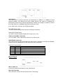
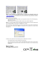
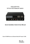
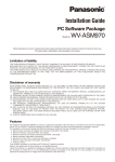
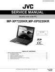
H.264 Multi-Profile 1CH Video Server
Quick Start Guide
2013 Mar.
About multi-profile
Multi-profile stands for simultaneously video streams. These Network Cameras can generate H.264,
MPEG4 and MJPEG streaming simultaneously to different clients. Moreover, the resolution can be
different from one client to another. This state-of-art design is considerable to fit in various network
environments.
Before Installation
Before installation, please be sure to read this quick installation guide and user’s manual carefully
to complete machine installation.
1. System Requirements
H.264 Multi-Profile 1CH Video Server
Network Environment
Network Interface
10/100MBase-TX Ethernet
Monitoring System Recommended for Internet Explorer 8.0 or later
System Hardware
· CPU: Pentium 4, 3.6GHz or higher
· Memory Size : 1GB or more
· VGA card resolution : 1024 x 768 or higher
- Sound card: for 2-way audio function
System Requirement for Viewer & Recorder Application
Support OS
Win XP, Win Vista, Win 7, Win 8
System Hardware
16 cameras surveillance application (typical)
· CPU: Intel Core 2 Quad 3GHz or higher
· Memory Size : 2GB or more
· VGA card resolution : 1024 x 768 or higher
System Requirement for Viewer & Recorder Application
Support OS Win XP, Vista, 7
FPS
~120
120~360
360~540
540~960
960~
(QVGA)
CPU
Intel P4
Intel P4
Intel Pentium D Intel core 2 Duo Intel core 2 Quad
2.4GHz
3.2GHz
950
E8600
Q9650
3.4GHZ
3.3GHZ
3.0GHZ
RAM
512MB
512MB
1GB
2GB
2GB
Display
support1024x768 resolution or above
Support DirectX 9.0c or above
Intel 945G or Intel 965G or above
60GB (free space)
Hard disk
Ethernet
100Mbps
Chipset
1Gbps
Intel 945 or Intel 965 or above
2. Physical Installation
2.1 Connections
Front Panel
2
LAN Socket
The LAN socket is a RJ-45 connector for connections to 10Base-T or 100Base-TX Fast
Ethernet cabling. This Ethernet port built N-Way protocol can detect or negotiate the
transmission speed of the network automatically. Please use Category 5 cable to connect
the Video Server to a 100Mbps Fast Ethernet switch or hub.
In the LAN socket, there are two LEDs embedded:
LAN LED (green color)
This LED will be flashing while network accessing via Ethernet.
Power LED (orange color)
This LED is used to indicate whether DC power is on or not.
Video-in Jack (BNC connector)
You can Install 1 video camera and connect it to video-in jack.
DI/DO/RS485 Connector
The Video Server provides a terminal block with 6 pins of connectors for DIDO and RS485.
Please refer to the Appendix A in this manual for more information.
Cable for I/O connectors:
Name Number
Function
VDC
1
12V DC output (50mA maximum)
DI
2
Digital signal input
GND
3
GND
DO
4
Digital signal output
485+
5
RS485 data +
4856
RS485 data -
Back Panel
MIC in (audio in)
Connect an external microphone to the Video Server.
Micro SD Card Slot
User can insert a micro SD card into this slot for recording.
3
Factory Default Reset
This button is hidden in the pinhole. This button is used to restore the all factory default
settings. Sometimes restarting the Video Server will make the system back to a normal
state. If the system still got problems after restart, user can restore the factory default
settings and install it again. To restore the device, please follow the steps below:
(i) Insert the paper clip or any proper tool and press and hold the button down
continuously.
(ii) Hold it at least 5 seconds and release the tool. Then the device has been
restored to default settings and reboot again.
Note: Restoring the factory default setting will lose the all previous settings included IP
address forever. User needs to run the IPWizard II program to search the device and
configure it to let the device work properly again.
Audio/Video Output Jack
Audio/Video-out Jack allows this device to output audio and video signal. Use the attached
A/V cable to connect A/V device where white cable is for audio and yellow cable is for
video.
DC Power Jack (12VDC out)
The function of this DC power jack depends on model:
2.1.1 Installation
1. Attach video source to Video Server
To use this video server, user must supply video source to this device first. Typical, user
may utilize box camera, doom camera, bullet camera, P/T/Z camera, Speed doom camera,
or others as the video source. Connect an external camera to the device’s video input and
make sure to power on these cameras first. Otherwise, the operation may be incorrect.
2. Attach external microphone to Video Server (option)
If user needs not only video stream but also audio stream, then an external microphone
should be attached to Video Server. Connect an external microphone to the Video Server’s
audio input.
3. Plug an Ethernet cable into Video Server
Connect an Ethernet cable to the LAN socket located on the device’s panel and attach it to
the network.
4. Connect RS485 (option)
When users would like to apply a camera with P/T/Z function, they usually need to connect
their communication port (for camera control) through RS485. After RS-485 was correctly
connected to D+ and D-, the remote users could control the camera movement through
Internet.
5. Connect an external power supply to Video Server
Connect an external power supply to the 12VDC power jack of the Video Server. Once you
have installed the Video Server well, the Power LED (orange) will turn on later. It means
the system is booting up successfully. Furthermore, if you have a proper network
connection, and access to the Video Server, the LAN LED (green) will flash.
4
6. Connect DC power to one external camera from Video Server (option)
In case your Video Server is connected to PoE switch, then this device can provide 12VDC
out to supply one external camera thru 12VDC power jack. Note that the output current is
300mA maximum.
7. Done
3. Camera administration
When you installed your networked device over your network environment, to start Network
Camera web configuration, you must have the web browsers installed on computer for web
management.
- Microsoft internet Explorer 6.0 or higher
At first, user may use “IP Wizard II” utility to search all networked devices in the LAN.
Use “IP Wizard II” to locate IP address
Press “Search” button. IP Wizard II will list all networked devices in the LAN:
View function:
If IP Wizard II finds network devices, View button will be available. Please select the device
you want to view and click the View button. Furthermore you could double click the left
button of mouse to link to the network device by browser.
LAN setting function:
The utility featured with “LAN” setting function to help user to modify the IP parameters of
the installed network devices. User can step by step to setup IP address, username and
password.
5
Note 1: If no IP address is assigned within 30 seconds, the networked device will
automatically assign 192.168.0.100. User may now open your web browser, and key in
http://192.168.0.100 in the address bar of you web browser to logon Network Camera’s
web configuration page.
Note 2: Power Line Frequency
- If you found the video image is flash, you may need to choose 50 or 60 Hz frequency
(depends on country).
- World wide power line frequency table is inside user’s manual, Appendix
Note 3: If you have problem when connecting the network camera to a router, please read
user’s manual inside CD, the section “Installation to a router”.
After connected to networked device, the device will prompt for User name and Password.
For the first time, please enter: admin as username and no password to continue Web
Management.
If difficulty is met, please refer to the following steps to establish the connection:
-
The networked device must be installed and powered ON.
-
If the networked device’s default IP Address (192.168.0.100) is already used by another device,
the other device must be turned OFF until the device is allocated a new IP Address during
configuration.
Made in Taiwan
All Rights Reserved 2013
6