1
Bull
2104 Model DU3 Expandable Storage Plus
Service Guide
ORDER REFERENCE
86 A1 17EF 01
Bull
2104 Model DU3 Expandable Storage Plus
Service Guide
Hardware
December 2000
BULL CEDOC
357 AVENUE PATTON
B.P.20845
49008 ANGERS CEDEX 01
FRANCE
ORDER REFERENCE
86 A1 17EF 01
The following copyright notice protects this book under the Copyright laws of the United States of America
and other countries which prohibit such actions as, but not limited to, copying, distributing, modifying, and
making derivative works.
Copyright
Bull S.A. 1992, 2000
Printed in France
Suggestions and criticisms concerning the form, content, and presentation of
this book are invited. A form is provided at the end of this book for this purpose.
To order additional copies of this book or other Bull Technical Publications, you
are invited to use the Ordering Form also provided at the end of this book.
Trademarks and Acknowledgements
We acknowledge the right of proprietors of trademarks mentioned in this book.
AIXR is a registered trademark of International Business Machines Corporation, and is being used under
licence.
UNIX is a registered trademark in the United States of America and other countries licensed exclusively through
the Open Group.
Year 2000
The product documented in this manual is Year 2000 Ready.
The information in this document is subject to change without notice. Groupe Bull will not be liable for errors
contained herein, or for incidental or consequential damages in connection with the use of this material.
Contents
Safety Notices. . . . . . . . . . . . . . . . . . . . . . . . vii
Definitions of Safety Notices . . . . . . . . . . . . . . . . . . . vii
Safety Notice for Installing, Relocating, or Servicing. . . . . . . . . . . . vii
About This Book . . . . . . . . . . . . . . . . . . . . . . . ix
Numbering Convention . . . . . . . . . . . . . . . . . . . . . ix
Trademarks . . . . . . . . . . . . . . . . . . . . . . . . . ix
Related Publications . . . . . . . . . . . . . . . . . . . . . . ix
Electrostatic Discharge . . . . . . . . . . . . . . . . . . . . . xi
Chapter 1. Reference Information . . . .
SCSI Interface Cards . . . . . . . . .
Error Logging. . . . . . . . . . . .
Configurations . . . . . . . . . . .
−48 Volt Power Supply (Model DU3 Only) . .
Lights and Switches . . . . . . . . .
Subsystem Lights . . . . . . . . .
SCSI Interface Card Lights . . . . . .
Fan-and-Power-Supply Assembly Lights and
Fan Assembly Light . . . . . . . .
Switch Card Assembly Switches . . . .
Disk Drive Module Lights . . . . . .
Parts Locations . . . . . . . . . .
Parts Locations (2104 Model DU3) . . .
Parts Locations (2104 Model TU3) . . .
Connectors . . . . . . . . . . . .
Back Connectors (2104 Model DU3). . .
Back Connectors (2104 Model TU3) . . .
Mainline-Power Connector (220 V ac) . .
Mainline-Power Connector (Model DU3, −48
Labels . . . . . . . . . . . . .
Product Characteristics . . . . . . . .
Dimensions and Weight (2104 Model DU3)
Dimensions and Weight (2104 Model TU3)
AC and DC Input-Voltage Requirements .
Environment . . . . . . . . . .
Altitude . . . . . . . . . . . .
Heat Output (Maximum) . . . . . . .
Disk Drive Acclimation . . . . . . . .
Power Sequencing . . . . . . . . .
SCSI Addresses . . . . . . . . . .
SCSI Bus Configurations and Addresses . .
Microcode Maintenance . . . . . . . .
Vital Product Data (VPD) . . . . . . .
SCSI Disk Drives . . . . . . . . .
2104 . . . . . . . . . . . . .
2104 Service Aids . . . . . . . . . .
. . .
. . .
. . .
. . .
. . .
. . .
. . .
. . .
Switch .
. . .
. . .
. . .
. . .
. . .
. . .
. . .
. . .
. . .
. . .
V dc) .
. . .
. . .
. . .
. . .
. . .
. . .
. . .
. . .
. . .
. . .
. . .
. . .
. . .
. . .
. . .
. . .
. . .
.
.
.
.
.
.
.
.
.
.
.
.
.
.
.
.
.
.
.
.
.
.
.
.
.
.
.
.
.
.
.
.
.
.
.
.
.
.
.
.
.
.
.
.
.
.
.
.
.
.
.
.
.
.
.
.
.
.
.
.
.
.
.
.
.
.
.
.
.
.
.
.
.
.
.
.
.
.
.
.
.
.
.
.
.
.
.
.
.
.
.
.
.
.
.
.
.
.
.
.
.
.
.
.
.
.
.
.
.
.
.
.
.
.
.
.
.
.
.
.
.
.
.
.
.
.
.
.
.
.
.
.
.
.
.
.
.
.
.
.
.
.
.
.
.
.
.
.
.
.
.
.
.
.
.
.
.
.
.
.
.
.
.
.
.
.
.
.
.
.
.
.
.
.
.
.
.
.
.
.
.
.
.
.
.
.
.
.
.
.
.
.
.
.
.
.
.
.
.
.
.
.
.
.
.
.
.
.
.
.
.
.
.
.
.
.
.
.
.
.
.
.
.
.
.
.
.
.
.
.
.
.
.
.
.
.
.
.
.
.
.
.
.
.
.
.
.
.
.
.
.
.
.
.
.
.
.
.
.
.
.
.
.
.
.
.
.
.
.
.
.
.
.
.
.
.
.
.
.
.
.
.
.
.
.
.
.
.
.
.
.
.
.
.
.
.
.
.
.
.
.
.
.
.
.
.
.
.
.
.
.
.
.
.
.
.
.
.
.
.
.
.
.
.
.
.
.
.
.
.
.
.
.
. 1
. 3
. 3
. 3
. 4
. 5
. 7
. 7
. 8
. 8
. 9
. 13
. 15
. 16
. 17
. 18
. 18
. 19
. 20
. 21
. 22
. 23
. 23
. 23
. 23
. 23
. 24
. 24
. 24
. 24
. 25
. 26
. 28
. 29
. 29
. 29
. 30
iii
2104 Enclosure Services . . . . .
Service Inspection Guide . . . . .
Inspection Checklist . . . . . .
Checking the Grounding of the 2104 .
Grounding Check (2104 Model DU3)
Grounding Check (2104 Model TU3)
iv
.
.
.
.
.
.
.
.
.
.
.
.
.
.
.
.
.
.
.
.
.
.
.
.
.
.
.
.
.
.
.
.
.
.
.
.
.
.
.
.
.
.
.
.
.
.
.
.
.
.
.
.
.
.
.
.
.
.
.
.
.
.
.
.
.
.
.
.
.
.
.
.
30
31
31
32
32
35
Chapter 2. Problem Determination Procedures .
Disk Drive Module Power-On Self-Tests (POSTs) .
SCSI Interface Card Power-On Self-Tests (POSTs) .
Service Request Numbers (SRNs) . . . . . .
The SRN Table. . . . . . . . . . . .
Using the SRN Table . . . . . . . . . .
FRU Names Used in the SRN Table. . . . .
The SRNs . . . . . . . . . . . . .
Maintenance Analysis Procedures (MAPs) . . . .
How to Use these MAPs . . . . . . . . .
MAP 2010: 2104 – START . . . . . . . . .
MAP 2020: 2104 – Power . . . . . . . . .
MAP 2022: 2104 – Power-On . . . . . . . .
MAP 2030: 2104 – Power Control . . . . . .
MAP 2340: 2104 – SCSI Bus . . . . . . . .
MAP 2410: 2104 – Repair Verification . . . . .
.
.
.
.
.
.
.
.
.
.
.
.
.
.
.
.
.
.
.
.
.
.
.
.
.
.
.
.
.
.
.
.
.
.
.
.
.
.
.
.
.
.
.
.
.
.
.
.
.
.
.
.
.
.
.
.
.
.
.
.
.
.
.
.
.
.
.
.
.
.
.
.
.
.
.
.
.
.
.
.
.
.
.
.
.
.
.
.
.
.
.
.
.
.
.
.
.
.
.
.
.
.
.
.
.
.
.
.
.
.
.
.
.
.
.
.
.
.
.
.
.
.
.
.
.
.
.
.
.
.
.
.
.
.
.
.
.
.
.
.
.
.
.
.
.
.
.
.
.
.
.
.
.
.
.
.
.
.
.
.
.
.
.
.
.
.
.
.
.
.
.
.
.
.
.
.
37
37
38
38
38
39
39
40
43
43
44
49
52
57
59
65
Chapter 3. Removal and Replacement Procedures .
Concurrent Maintenance . . . . . . . . . .
Cover . . . . . . . . . . . . . . . . .
All Power. . . . . . . . . . . . . . . .
Power (2104 Model DU3) . . . . . . . . .
Power (2104 Model TU3) . . . . . . . . .
Disk Drive Modules and Dummy Disk Drive Modules .
Removing a Module . . . . . . . . . . .
Installing a Module . . . . . . . . . . .
SCSI Bus Bridge Card Assembly . . . . . . . .
Removing the SCSI Bus Bridge Card Assembly . .
Installing the SCSI Bus Bridge Card Assembly . .
Fan-and-Power-Supply Assemblies . . . . . . .
Fan Assembly . . . . . . . . . . . . . .
SCSI Interface Card Assembly . . . . . . . .
Switch Card Assembly . . . . . . . . . . .
Frame Assembly . . . . . . . . . . . . .
2104 Model DU3 . . . . . . . . . . . .
2104 Model TU3 . . . . . . . . . . . .
Removing a 2104 Model DU3 from a Rack . . . .
Support Rails . . . . . . . . . . . . . .
.
.
.
.
.
.
.
.
.
.
.
.
.
.
.
.
.
.
.
.
.
.
.
.
.
.
.
.
.
.
.
.
.
.
.
.
.
.
.
.
.
.
.
.
.
.
.
.
.
.
.
.
.
.
.
.
.
.
.
.
.
.
.
.
.
.
.
.
.
.
.
.
.
.
.
.
.
.
.
.
.
.
.
.
.
.
.
.
.
.
.
.
.
.
.
.
.
.
.
.
.
.
.
.
.
.
.
.
.
.
.
.
.
.
.
.
.
.
.
.
.
.
.
.
.
.
.
.
.
.
.
.
.
.
.
. 67
. 67
. 68
. 71
. 71
. 73
. 75
. 75
. 80
. 85
. 85
. 87
. 89
. 94
. 97
. . . . . . . . . . 102
. . . . . . . . . . 106
. . . . . . . . . . 107
. . . . . . . . . . 112
. . . . . . . . . . 115
. . . . . . . . . . 120
Chapter 4. Parts Catalog. . .
Conventions . . . . . . .
Assembly 1: 2104 Model DU3 .
Assembly 2: 2104 Model TU3 .
.
.
.
.
2104 Service Guide
.
.
.
.
.
.
.
.
.
.
.
.
.
.
.
.
.
.
.
.
.
.
.
.
.
.
.
.
.
.
.
.
.
.
.
.
.
.
.
.
.
.
.
.
.
.
.
.
.
.
.
.
.
.
.
.
.
.
.
.
.
.
.
.
.
.
.
.
.
.
.
.
.
.
.
.
.
.
.
.
.
.
123
123
124
126
Country Power Cables .
|
|
|
|
|
|
|
|
|
|
|
|
|
|
|
|
|
.
.
.
.
.
.
.
.
.
.
.
.
.
.
.
.
.
.
.
. 128
Appendix A. Additional Information for RISC Systems . . . .
Related Publications . . . . . . . . . . . . . . . .
Web Support Page . . . . . . . . . . . . . . . . .
SCSI Adapters . . . . . . . . . . . . . . . . . .
Location Code Format . . . . . . . . . . . . . . . .
System Service Aids . . . . . . . . . . . . . . . .
Format Media . . . . . . . . . . . . . . . . . .
Certify Media . . . . . . . . . . . . . . . . . .
SCSI Device Identification and Removal . . . . . . . . .
Download Microcode to a Disk Drive or to a SCSI Interface Card.
Software and Microcode Errors . . . . . . . . . . . . .
Diagnostics Information . . . . . . . . . . . . . . .
Concurrent Diagnostics . . . . . . . . . . . . . .
Nonconcurrent Diagnostics . . . . . . . . . . . . .
Problems Corrected . . . . . . . . . . . . . . . .
Collecting Errors . . . . . . . . . . . . . . . . . .
Configuring a Disk Drive Module to the Using System . . . . .
Configuring a 2104 to the Using System . . . . . . . . . .
Unconfiguring a 2104 from the Using System . . . . . . . .
.
.
.
.
.
.
.
.
.
.
.
.
.
.
.
.
.
.
.
.
.
.
.
.
.
.
.
.
.
.
.
.
.
.
.
.
.
.
.
.
.
.
.
.
.
.
.
.
.
.
.
.
.
.
.
.
.
.
.
.
.
.
.
.
.
.
.
.
.
.
.
.
.
.
.
.
.
.
.
.
.
.
.
.
.
.
.
.
.
.
.
.
.
.
.
131
131
131
132
133
134
134
134
135
136
137
137
137
137
137
138
139
139
139
Appendix B. Cable Configurations . . . . . . . . . . . . . . .
AIX Versions . . . . . . . . . . . . . . . . . . . . . . .
Adapter Microcode . . . . . . . . . . . . . . . . . . . . .
Configurations That Are Valid for 2104 Models DU3 and TU3 . . . . . . .
Adapters . . . . . . . . . . . . . . . . . . . . . . .
Summary of SCSI Bus Configurations . . . . . . . . . . . . . .
Examples of Single-Bus Mode Configurations . . . . . . . . . . .
Examples of Dual-Bus Mode Configurations . . . . . . . . . . . .
Configurations That Are Not Valid for 2104 Models DU3 and TU3 . . . . .
Two Adapters in One Using System Connected to One 2104 . . . . . .
One Adapter in One Using System Connected to Two 2104s via the SCSI
Interface Card Assemblies . . . . . . . . . . . . . . . . .
One Adapter in One Using System Connected to 2104s via a Y-Cable (1)
One Adapter in One Using System Connected to 2104s via a Y-Cable (2)
One Dual-Channel Non-RAID Adapter in One Using System Connected to Two
2104s and Internal Disk Drives . . . . . . . . . . . . . . .
One RAID Adapter in Each of Two Using Systems Connected to Two 2104s
.
.
.
.
.
.
.
.
.
.
141
141
141
142
142
143
144
151
157
157
Appendix C. Communications Statements . . . . . . . . .
Federal Communications Commission (FCC) Statement . . . . . .
Japanese Voluntary Control Council for Interference (VCCI) Statement .
Korean Government Ministry of Communication (MOC) Statement . .
New Zealand Compliance Statement . . . . . . . . . . . .
International Electrotechnical Commission (IEC) Statement . . . . .
Avis de conformité à la réglementation d’Industrie Canada . . . . .
Industry Canada Compliance Statement . . . . . . . . . . .
United Kingdom Telecommunications Requirements . . . . . . .
European Union (EU) Statement . . . . . . . . . . . . .
.
.
.
.
.
.
.
.
.
.
163
163
163
163
163
164
164
164
164
164
Contents
v
.
.
.
.
.
.
.
.
.
.
.
.
.
.
.
.
.
.
.
.
.
.
.
.
.
.
.
.
.
.
. 158
159
160
. 161
162
Radio Protection for Germany . . .
Taiwan Class A Compliance Statement
vi
.
.
.
.
.
.
.
.
.
.
.
.
.
.
.
.
.
.
.
.
.
.
.
.
.
.
.
.
. 164
. 165
Appendix D. Translated Safety Notices
.
.
.
.
.
.
.
.
.
.
.
.
.
. 167
Index
.
.
.
.
.
.
.
.
.
.
.
.
.
. 201
2104 Service Guide
.
.
.
.
.
.
.
.
.
.
.
.
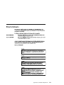
Safety Notices
For a translation of the danger and caution notices contained in this book, see
“Appendix D. Translated Safety Notices” on page 167.
Definitions of Safety Notices
A danger notice indicates the presence of a hazard that has the potential of causing
death or serious personal injury.
This book contains a danger notice on pages 72, and 92.
A caution notice indicates the presence of a hazard that has the potential of causing
moderate or minor personal injury.
This book contains caution notices on pages: 92, 95, 100, 105, 107, 110, 113, 115, and
119.
An attention notice indicates an action that could cause damage to a program, device,
system, or data.
Safety Notice for Installing, Relocating, or Servicing
Before connecting or removing any cables to or from connectors at the using system,
be sure to follow the steps in the installation or relocation checklist specified in the
Installation and Service Guide, or equivalent, for your using system.
For safety checks when servicing, refer to “Service Inspection Guide” on page 31.
vii
viii
2104 Service Guide
About This Book
This book provides service information for any person who is required to service
Expandable Storage Plus: 2104 Models DU3 and TU3 disk subsystems. That person
could be a technically-qualified employee of the owner of the subsystem, or a service
representative. This information is organized as follows:
v Chapter 1 briefly introduces the 2104, and gives useful reference information.
v Chapter 2 gives problem determination procedures.
v Chapter 3 gives removal and replacement procedures.
v Chapter 4 is the parts catalog.
v Appendix A gives additional information for 2104s that are attached to RISC systems.
v Appendix B shows examples of cable configurations for the 2104.
v Appendix C contains communications statements for the 2104.
|
v Appendix D gives translations of the safety notices that appear in this book.
An index is provided at the back of the book.
Important: This book does not include service information for 2104 Models DL1 and
TL1. For those models, see Related Publications in Appendix A. Additional
Information for RISC Systems.
Numbering Convention
In this book:
v One kilobyte (KB) equals 1 000 bytes.
v One megabyte (MB) equals 1 000 000 bytes.
v One gigabyte (GB) equals 1 000 000 000 bytes.
Trademarks
The following items are trademarks of International Business Machines Corporation in
the United States, or other countries, or both.
AIX
IBM
RS/6000
^™
Related Publications
The Installation and Service Guide, or equivalent, for your using system
Expandable Storage Plus: 2104 Models DU3 and TU3: Operator’s Guide,
86 A1 16EF
Expandable Storage Plus: 2104 Model DU3 Installation Guide, 86 A1 15EF
ix
Expandable Storage Plus: 2104 Model TU3 Installation Guide,
For other publications, see “Related Publications” in Appendix A. Additional Information
for RISC Systems.
x
2104 Service Guide
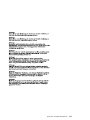
Electrostatic Discharge
When you handle field-replaceable units (FRUs) and other computer parts, take these
precautions to avoid static damage:
v Limit your movement. Movement can cause static electricity to build up around you.
v Always touch computer parts carefully. Hold adapters and memory-modules by their
edges. Never touch any exposed circuits.
v Prevent people who are not correctly grounded from touching computer parts.
v Before you install a new part, touch the static-protective package that contains the
part against an unpainted metal part of the 2104 or using system for at least two
seconds. This action reduces static electricity in the package and in your body.
v Remove the part from its package and, if possible, install it directly into the 2104
without putting the part down. If you need to put the part down, first place the
static-protective package that contained the part onto a smooth, level surface, then
place the part onto the package.
v Do not place the part onto any metal surface.
About This Book
xi
Safety Note
Ensure that you read “Safety Notices” on page vii before you do any of the
actions that are described in this book.
xii
2104 Service Guide
Chapter 1. Reference Information
Are You Using the Correct Book? Do not use this book if you are servicing a 2104
Model DL1 or TL1. For the correct book, see Related Publications in Appendix A.
Additional Information for RISC Systems.
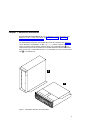
The Expandable Storage Plus: 2104 Models DU3 and TU3 subsystems (see Figure 1)
can be attached to any RS/6000™ or IBM ™ ^™ pSeries computer that provides
support for Small Computer System Interface (SCSI). The 2104 Model DU3 1 is a
rack-mounted unit that can be installed into a standard Electrical Industries Association
(EIA) 19-inch rack, a 7104 Model T00 rack, or a 7104 Model T42 rack. The 2104 Model
TU3 2 is a deskside unit.
Figure 1. 2104 Models DU3 and TU3 Subsystems
1
The 2104 Models DU3 and TU3 can contain up to 14 SCSI disk drive modules. These
modules can be a mixture of various types, which vary in size (see “Chapter 4. Parts
Catalog” on page 123).
The 2104 can be disconnected from its related SCSI attachments (for example, SCSI
adapters) while the using system is running. Also, most of the field-replaceable units
(FRUs) of the 2104 can be removed and replaced while the 2104 and the using system
are running. For a list of those FRUs, see “Concurrent Maintenance” on page 67.
The 2104 has two fan-and-power-supply assemblies, or one fan-and-power-supply
assembly and one fan assembly, to provide all the necessary power and cooling. It also
has up to two SCSI interface cards, which monitor and control the various functions of
the 2104 (see also “SCSI Interface Cards” on page 3). Each SCSI interface card can be
accessed to collect enclosure information only if it is connected to a SCSI attachment. A
switch card assembly provides option selection switches (see also “Switch Card
Assembly Switches” on page 9).
The 2104 can be configured to the using system as a device if applicable. See
“Configuring a 2104 to the Using System” in “Appendix A. Additional Information for
RISC Systems”. When a 2104 is configured as a device:
v Errors that are detected in the 2104 can be collected by the diagnostics.
v Vital product data (VPD) for the 2104 can be accessed.
Most FRUs contain their own vital product data (VPD). A using system can access this
VPD while the 2104 is being configured.
Enclosure configuration information is stored in several locations in the 2104 to allow
concurrent replacement of FRUs. When a new FRU is installed, any special
configuration information that is required by that FRU is read from other locations in the
2104. That information is then used to update the new FRU. To ensure that the
configuration is not corrupted or changed, always exchange FRUs one at a time.
2
2104 Service Guide
SCSI Interface Cards
The SCSI interface card of the 2104:
v Provides SCSI Enclosure Services (SES).
v Reads the VPD from the backplanes and the fan-and-power-supply assemblies.
v Controls the Subsystem Check light and the disk drive module Check lights.
v Controls the speed of the fan of the fan-and-power-supply assemblies or
fan-and-power-supply assembly and fan assembly.
v Monitors the ‘Emergency Power Off Warning (EPOW)’ signal from the power-supply
assembly or assemblies. If an ‘EPOW’ signal occurs, the SCSI interface card sends
a ‘SCSI Reset’ signal to all the disk drive modules.
v Provides support for the hot plugging of the disk drive modules.
v Monitors itself. The SCSI interface card detects a self-failure if:
– The microprocessor fails.
– An SES function fails.
– The enclosure temperature is outside the specified limits.
v Provides support for SCSI Ultra 160 MB per second operation, LVD (Low Voltage
Differential) mode.
Note: It does not provide support for SE (Single Ended) mode.
If the 2104 has two SCSI interface cards, each SCSI interface card can be accessed to
collect enclosure information only if it is connected to a SCSI attachment. If both cards
are operational, the SES-active card provides all the functions described here. The
other card only detects self-failure and drives the internal SCSI bus.
Error Logging
Errors that the 2104 detects are not automatically logged to the system error log.
To collect error data, run diagnostics. For more details, see “Collecting Errors” in
“Appendix A. Additional Information for RISC Systems”.
Configurations
Each SCSI interface card can be attached to only one using system. A 2104 that has
one SCSI interface card can, therefore, be attached to only one using system. A 2104
that has two SCSI interface cards can be attached to two using systems. No SCSI
terminators are needed.
Chapter 1. Reference Information
3
−48 Volt Power Supply (Model DU3 Only)
The −48 Volt Power Supply feature provides power supply assemblies that allow a 2104
Model DU3 to be connected to −48 volt power sources. The 2104 must be connected to
two separate power sources to ensure that operations are not interrupted if one power
source fails. The −48 Volt power distribution panel (PDP) in the rack provides the power
sources and the power cables. For details about how to connect a 2104 Model DU3 to
a −48 volt power source, see the 2104 Model DU3: Installation Guide.
Attention:
v If the −48 Volt PDP uses 15-amp circuit breakers, and the 2104 contains at least one
18.2 GB, 10000 rpm disk drive module, the 2104 must contain no more than nine
disk drive modules. Otherwise, no limitations exist for other types of disk drive
module.
If the −48 Volt PDP uses 20-amp circuit breakers, no limitations exist for any types of
disk drive module.
v Both power supply assemblies in a 2104 must be of the same voltage rating. Do not
mix power supply assemblies of different voltage ratings.
4
2104 Service Guide
Lights and Switches
The lights and switches of the 2104 consist of:
v Subsystem lights
v SCSI interface card lights
v Fan-and-power-supply assembly lights and switch
v Fan assembly light
v Switch card assembly switches
v Disk drive module lights
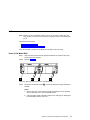
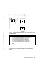
Figure 2 shows the lights and switches of the 2104 Model DU3; Figure 3 shows the
lights and switches of the 2104 Model TU3.
Figure 2. Lights and Switches of the 2104 Model DU3
Chapter 1. Reference Information
5
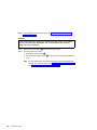
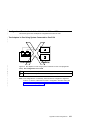
Figure 3. Lights and Switches of the 2104 Model TU3
6
2104 Service Guide
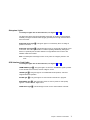
Subsystem Lights
To identify the lights that are described here, see Figures 2 and 3.
The Subsystem Power light and Subsystem Check light are located on the backplane
assembly. The lights are made visible by light pipes that pass through the bezel at the
front of the 2104.
Subsystem Power light 1: This green light is on continuously when dc voltage is
present in the 2104.
Subsystem Check light 2: This amber light comes on continuously if a failure occurs
in the 2104. The 2104 might be able to continue operating satisfactorily although the
failure of a particular part has been detected. The light flashes when a service aid
identifies a disk drive module.
Note: The Subsystem Check light comes on only when dc voltage is present in the
2104.
SCSI Interface Card Lights
To identify the lights that are described here, see Figures 2 and 3.
TERM POWER light 3: This green light is on when the ‘TERMPWR’ signal is present
on the external SCSI connector, and the voltage is correct.
LVD/SE light 4: This green light is on for differential SCSI operation, and off for
single-ended SCSI operation.
ACTIVE light 5: This green light is on when a SCSI command is in progress.
SCSI RESET light 6: This green light comes on when a ‘power-on reset’ (POR)
signal or a ‘SCSI bus reset’ signal occurs.
CARD FAULT light 7: This amber light comes on if the SCSI interface card fails.
Chapter 1. Reference Information
7
Fan-and-Power-Supply Assembly Lights and Switch
To identify the lights and switch that are described here, see Figures 2 and 3.
DC On/Standby switch 10: This switch switches off the dc electrical power to the
disk drive modules and other components of the 2104. The switch must be set to On
for the power supply and the fan unit to start.
If the DC On/Standby switch is set to On (on either fan-and-power-supply assembly, if
two are present), dc power in the 2104 is turned on automatically if all the following
conditions exist:
v Mainline power is present at the 2104.
v At least one fan-and-power-supply assembly is correctly installed.
v Either the Power Control switch on the Switch card assembly is set to On or
terminator power is active in an external SCSI connection.
CHK light 11: This amber light is on continuously if the fan-and-power-supply
assembly fails or goes into Standby mode. When a power supply fails, the CHK light
gets its power from the other fan-and-power-supply assembly (if present). The light can,
therefore, indicate a critical power supply failure only if the 2104 has two
fan-and-power-supply assemblies.
Note: The CHK light is active only when the DC On/Standby switch is set to On.
DC PWR light 12: This green light is on when the power supply assembly is
supplying dc power to the 2104.
AC PWR light 13: This green light is on when mainline electrical power is present in
the power supply assembly.
Fan Assembly Light
To identify the light that is described here, see Figures 2 and 3.
CHK light 8: This amber light comes on if the fan fails.
8
2104 Service Guide
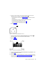
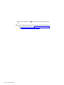
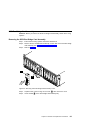
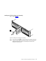
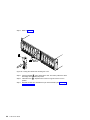
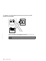
Switch Card Assembly Switches
The switch card assembly is item 9 in Figures 2 and 3. To identify the switch card
assembly switches, refer to Figure 4.
Figure 4. Switch Card Assembly Switches
Notes:
1. In this section, “default logical setting” means the setting that the enclosure uses if
the switch card assembly is not present when a power-on or reset operation occurs.
2. Switch 10 is not used, and must always be set to Off.
Chapter 1. Reference Information
9
External Switches
Power Control switch 1: When this switch is set to Off, the SCSI interface card can
enable the 2104 power supplies if both the following conditions exist:
v The 2104 is connected to mainline power and a DC On/Standby (on a
fan-and-power-supply assembly) is set to On.
v The ‘terminator power (TERMPWR)’ signal is active in an external SCSI connection.
Under these conditions, the SCSI interface card provides a remote power on control
function. That is, the 2104 switches off automatically when all the connected using
systems switch off; it switches on automatically when one using system switches on.
When the Power Control switch is set to On, power is not controlled by the ‘TERMPWR’
signal. The 2104 does not switch on and off automatically with the using system.
If the switch card assembly is not present when the 2104 is first switched on, or when
the 2104 receives a ‘Reset’ signal, the default logical setting for this switch is Off.
Drive Autostart switch 2 : When this switch is set to On, the motors of the disk drive
modules do not start until a Start Motor command is issued. The timing sequence of
startup is under the control of the using-system software. When this switch is set to Off,
the disk drive modules are set to Delay Motor Start mode. The delay time before motor
startup is specified by the disk drive modules. After power is switched on, the delay
time is usually SCSI ID x 12 seconds. For example, the delay for a disk drive module
whose SCSI ID is 2 is 2x12 seconds (24 seconds).
If the switch card assembly is not present when the 2104 is first switched on, or when
the 2104 receives a ‘Reset’ signal, the default logical setting for this switch is On.
Enable Enclosure Services switch 3: When the switch is set to On, the SCSI
enclosure services operate. When the switch is set to Off, the 2104 does not respond to
requests for enclosure services, and SCSI address 15 (the address of the SCSI
enclosure services) is not used.
If the switch card assembly is not present when the 2104 is first switched on, or when
the 2104 receives a ‘Reset’ signal, the default logical setting for this switch is On.
Select Enclosure Services switch 4: When the switch is set to On, the SCSI
enclosure services are selected. When the switch is set to Off, the SAF-TE enclosure
services are selected.
Note: SAF-TE services are not supported on an RS/6000 or IBM ^ pSeries
system.
If the switch card assembly is not present when the 2104 is first switched on, or when
the 2104 receives a ‘Reset’ signal, the default logical setting for this switch is On.
Delay Motor Start Mode switch 5: This switch selects either Delay Motor Start Mode
or Normal Start Mode when the Drive Autostart switch 2 is set to Off. When the Delay
Motor Start Mode switch is set to On, Delay Motor Start mode is selected. The delay
10
2104 Service Guide
time before motor startup is specified for each disk drive module. After power is
switched on, the delay time is usually SCSI ID x 12 seconds. For example, the delay for
a disk drive module whose SCSI ID is 2 is 2x12 seconds (24 seconds).
If the switch card assembly is not present when the 2104 is first switched on, or when
the 2104 receives a ‘Reset’ signal, the default logical setting for this switch is Off.
Enclosure ID switch 6: This 10-position rotary switch sets the ID of the 2104. The
software uses the setting of this switch to identify the enclosure.
If the switch card assembly is not present when the 2104 is first switched on, or when
the 2104 receives a ‘Reset’ signal, the default logical setting for this switch is 0.
Internal Switches
The following switches can be accessed only when the switch card assembly is
removed from the 2104. In service operations, these switches need be checked and, if
necessary, set only when a replacement switch card assembly is installed.
SCSI Address switch 7: This switch, when set to On, reverses the SCSI addresses
of the disk drive modules. The default setting for this switch is Off.
On a 2104 Model DU3, the leftmost disk drive module slot has the lowest SCSI
address; the rightmost slot has the highest SCSI address (see Table 1 on page 25). If
the switch is set to On, the SCSI addresses are reversed. The leftmost disk drive
module slot has the highest SCSI address; the rightmost slot has the lowest SCSI
address. Do not use reversed addresses on the 2104 Model DU3.
Note: On the 2104 Model DU3, the physical numbers of the disk drive module slots
are always 1 through 14, from left to right.
On a 2104 Model TU3, the topmost disk drive module slot has the highest SCSI
address; the bottommost slot has the lowest SCSI address (see Table 1 on page 25). If
the switch is set to On, the SCSI addresses are reversed. The topmost disk drive
module slot now has the lowest SCSI address; the bottommost slot has the highest
SCSI address. Do not use reversed addresses on the 2104 Model TU3.
Note: On the 2104 Model TU3, the physical numbers of the disk drive module slots
are always 1 through 14, from bottom to top.
If the switch card assembly is not present when the 2104 is first switched on, or when
the 2104 receives a ‘Reset’ signal, the default logical setting for this switch is Off.
2104 Orientation switch 8: This switch must be set to Off for the 2104 Model DU3,
and to On for the 2104 Model TU3:
v When the switch is set for the 2104 Model DU3, the two-color LEDs that are related
to the 2104 Power light and to the 2104 Check light are set so that the left-hand LED
becomes the green Power light, and the right-hand LED becomes the amber Check
light.
Chapter 1. Reference Information
11
v When the switch is set for the 2104 Model TU3, the two-color LEDs that are related
to the 2104 Power light and to the 2104 Check light are set so that the upper LED
becomes the green Power light, and the lower LED becomes the amber Check light.
If the switch card assembly is not present when the 2104 is first switched on, or when
the 2104 receives a ‘Reset’ signal, the default logical setting for this switch is Off (that
is, for Model DU3).
SCSI Bus Split switch 9: This switch controls the SCSI bus configuration. When the
switch is set to Off, the 2104 is configured in single SCSI bus mode. When the switch is
set to On, the 2104 is configured in dual SCSI bus (split bus) mode.
If a 2104 Model DU3 is in dual SCSI bus mode and the SCSI address switch 7 is set
to Off , the SCSI addresses of one SCSI bus are 0 through 6 from left to center, and
the SCSI addresses of the other SCSI bus are 8 through 14 from center to right. If the
SCSI address switch is set to On, the SCSI addresses of one SCSI bus are 14 through
8 from left to center, and the SCSI addresses of the other SCSI bus are 6 through 0
from center to right.
If a 2104 Model TU3 is in dual SCSI bus mode and the SCSI address switch 7 is set
to Off , the SCSI addresses of one SCSI bus are 0 through 6 from bottom to center,
and the SCSI addresses of the other SCSI bus are 8 through 14 from center to top. If
the SCSI address switch is set to On, the SCSI addresses of one SCSI bus are 14
through 8 from bottom to center, and the SCSI addresses of the other SCSI bus are 6
through 0 from center to top.
If the switch card assembly is not present when the 2104 is first switched on, or when
the 2104 receives a ‘Reset’ signal, the default logical setting for this switch is Off.
Reserved 10: This switch must always be set to Off.
12
2104 Service Guide
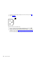
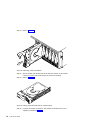
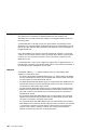
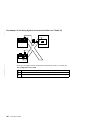
Disk Drive Module Lights
Figure 5. Disk Drive Module Lights
The disk drive module light (LEDs) are located on the backplane of the 2104. They are
made visible by light pipes that pass through the disk drive module.
1 Activity light: When on, this green light shows that a SCSI command is in
progress.
2 Check light: This amber light shows the following conditions:
Status of Light
Off
Permanently on
Meaning
Normal operating condition.
One of the following conditions exists:
v If a disk drive module is present, the service aid has set Remove
(see “SCSI Device Identification and Removal” in “Appendix A.
Additional Information for RISC Systems”).
v If a disk drive module is not present, the service aid has set
Insert (see “SCSI Device Identification and Removal” in
“Appendix A. Additional Information for RISC Systems”).
v The disk drive has reported a Predictive Failure Analysis (PFA)
error. This error indicates that the disk drive has had an
excessive number of internally recovered errors.
Slow flash (two seconds on,
two seconds off)
v The disk drive module is failing.
The Check light has been set by a service aid to identify the
position of this particular disk drive module.
Chapter 1. Reference Information
13
Fast flash (0.25 seconds on,
0.25 seconds off)
14
2104 Service Guide
The disk drive module is a member of a RAID array, and is being
rebuilt. (This action is a SAF-TE function.)
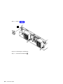
Parts Locations
This section has two subsections; one is for the 2104 Model DU3, the other is for the
2104 Model TU3. Go to the appropriate subsection.
Chapter 1. Reference Information
15
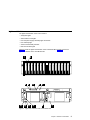
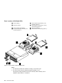
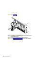
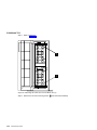
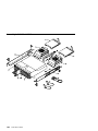
Parts Locations (2104 Model DU3)
1 Frame assembly
2 Disk drive modules
3 SCSI bus bridge card assembly
4 Fan-and-power-supply assembly or fan
assembly (position 2)
5 Fan-and-power-supply assembly or fan
assembly (position 1)
6 SCSI interface card assembly or dummy
card assembly (position 2)
7 Switch card assembly
8 SCSI interface card assembly (position 1)
Figure 6. Parts Locations of the 2104 Model DU3
Notes:
1. The disk drive modules are numbered 1 through 14 from left to right.
2. The 2104 can have two fan-and-power-supply assemblies or one
fan-and-power-supply assembly and one fan assembly. Either assembly can be
installed in either position 1 or position 2.
16
2104 Service Guide
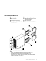
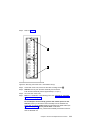
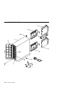
Parts Locations (2104 Model TU3)
1 Frame assembly
2 Disk drive modules
3 SCSI bus bridge card assembly
4 Fan-and-power-supply assembly or fan
assembly (position 2)
5 Fan-and-power-supply assembly or fan
assembly (position 1)
6 SCSI interface card assembly or dummy
card assembly (position 2)
7 Switch card assembly
8 SCSI interface card assembly (position 1)
Figure 7. Parts Locations of the 2104 Model TU3
Notes:
1. The disk drive modules are numbered 1 through 14 from bottom to top.
2. The 2104 can have two fan-and-power-supply assemblies or one
fan-and-power-supply assembly and one fan assembly. Either assembly can be
installed in either position 1 or position 2.
Chapter 1. Reference Information
17
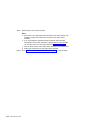
Connectors
This section shows the locations of the external connectors of the 2104.
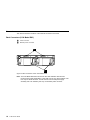
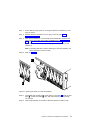
Back Connectors (2104 Model DU3)
1
SCSI connectors
2
Mainline power connectors
Figure 8. Back Connectors of the 2104 Model DU3
Note: The 2104 Model DU3 that is shown has two SCSI interface cards and two
fan-and-power-supply assemblies. A 2104 that has only one SCSI interface card
has only one SCSI connector. A 2104 that has one fan-and-power-supply
assembly and a fan assembly has only one mainline power connector.
18
2104 Service Guide
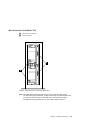
Back Connectors (2104 Model TU3)
1
Mainline power connectors
2
SCSI connectors
Figure 9. Back Connectors of the 2104 Model TU3
Note: The 2104 Model TU3 that is shown has two SCSI interface cards and two
fan-and-power-supply assemblies. A 2104 that has only one SCSI interface card
has only one SCSI connector. A 2104 that has one fan-and-power-supply
assembly and a fan assembly has only one mainline power connector.
Chapter 1. Reference Information
19
Mainline-Power Connector (220 V ac)
This type of connector is on each fan-and-power-supply assembly. It permits the 2104
to be connected to a mainline power source.
1
2
3
Ground
Neutral
Live
Figure 10. Mainline-Power Connector (220 V ac). The diagram shows the connector for
a Model DL1 (left), and for a Model TL1 (right).
20
2104 Service Guide
Mainline-Power Connector (Model DU3, −48 V dc)
This type of connector is on each −48 V power supply assembly.
Figure 11. Mainline-Power Connector (−48 V dc)
Pin
Assignment
Pin
Assignment
1
2
3
4
5
6
Frame ground
Not used
−48 V return (0 V)
−48 V return (0 V)
−48 V in
−48 V in
7
8
9
10
11
12
Frame ground
Not used
−48 V return (0V)
−48 V return (0V)
−48 V in
−48 V in
Chapter 1. Reference Information
21
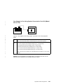
Labels
1
Serial number (2104 Model DU3)
2
Serial number (2104 Model TU3)
3
Serial number and size (disk drive
module)
Figure 12. Serial-Number Labels
22
2104 Service Guide
Product Characteristics
Dimensions and Weight (2104 Model DU3)
Height
Width
Depth
Approximate
Minimum
Weight
Approximate
Maximum
Weight
128 mm
445 mm
552 mm
23.0 kg
38.5 kg
(5 in.)
(18 in.)
(22 in.)
(51 lb)
(85 lb)
Dimensions and Weight (2104 Model TU3)
Height
Width at Foot
Depth
Approximate
Minimum
Weight
Approximate
Maximum
Weight
529 mm
281 mm
594 mm
39.6 kg
54.5 kg
(21 in.)
(11 in.)
(23.5 in.)
(87 lb)
(120 lb)
AC and DC Input-Voltage Requirements
Power Supply Assembly
Type
Voltage
Frequency
220 V
100 to 240 V ac
47 to 63 Hz
−48 V
−40 to −60 V dc
–
Environment
Operating
Environment
Nonoperating
Environment
Storing
Environment
Shipping
Environment
Relative
Humidity
10°C to 40°C
(50°F to 104°F)
8% to 80%
noncondensing
10°C to 52°C
(50°F to 125°F)
8% to 80%
noncondensing
1°C to 60°C
(34°F to 140°F)
5% to 80%
noncondensing
Maximum wet bulb
27°C (80°F)
27°C (80°F)
29°C (84°F)
–40°C to 60°C
(–40°F to 140°F)
5% to 100%
condensing but
not precipitating
29°C (84°F)
Air temperature
Notes:
1. Each rack-mounted 2104 Model DU3 requires an airflow of 1.1 m³ per minute (40
ft³ per minute). When racks containing many 2104s are to be installed together, the
following requirements must be met to ensure that the 2104s are adequately cooled:
v The airflow enters at the front of the rack and leaves at the back. To prevent the
air that is leaving the rack from entering the intake of another piece of equipment,
racks should be positioned in alternate rows, back-to-back and front-to-front.
Chapter 1. Reference Information
23
v The front of racks should be positioned on floor-tile seams, with a full line of
perforated tiles immediately in front of the racks.
v Where racks are in rows front-to-front or back-to-back, there should be a gap of
at least 1220 mm (48 in) separating the rows.
v To ensure correct air flow within each rack, the rack filler plates must be installed
in unused positions. Also, all the gaps in the front of the racks must be sealed,
including the gaps between the 2104s.
2. The recommended operating temperature is 22°C (72°F) or lower.
Altitude
Altitude
(from sea level)
Operating
Environment
Nonoperating
Environment
Storing
Environment
Shipping
Environment
0 to 2133 m
(0 to 7000 ft)
–305 to 12 192 m
(–1000 to 40 000 ft)
–305 to 12 192 m
(–1000 to 40 000 ft)
–305 to 12 192 m
(–1000 to 40 000 ft)
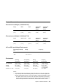
Heat Output (Maximum)
Maximum configuration (10 disk drive modules)
330 watts (1126 Btu per hour)
Disk Drive Acclimation
If you bring a disk drive module into the operating environment from an environment
where the temperature is outside the specified operating range (see Environment),
allow the disk drive module time to acclimate to the operating environment
(approximately 2 hours). Remove the disk drive module from any shipping packaging,
but leave it in its sealed plastic bag (if present) to prevent condensation forming.
Power Sequencing
You can configure the power sequencing of the 2104 Models DU3 and TU3. For more
information, see “Drive Autostart switch” on page 10.
24
2104 Service Guide
SCSI Addresses
Each disk drive module is identified to the using system by a SCSI address. This
address is related to the slot in which the disk drive module is installed. Although the
SCSI address switch (see “Switch Card Assembly Switches” on page 9) allows the
addresses of the slots to be reversed, do not use reversed settings; they are not
supported on 2104 Models DU3 and TU3.
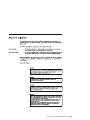
Table 1 shows the SCSI addresses of the slots.
Note: In the 2104 Model DU3, slot 1 is the leftmost slot (viewed from the front of the
2104). In the 2104 Model TU3, slot 1 is the bottommost slot (viewed from the
front of the 2104).
Table 1. SCSI Addresses of Disk Drive Module Slots
Disk drive module
slot
1
2
3
4
5
6
7
8
9
10
11
12
13
14
Device SCSI
address
0
1
2
3
4
5
6
8
9
10
11
12
13
14
Note: If the 2104 is configured for single SCSI bus mode with two SCSI attachments,
SCSI addresses 5 and 6 cannot be used; that is, disk drive module slots 6 and 7
must contain dummy disk drive modules.
The SCSI enclosure services (SES) use address 15 if the Enable Enclosure Services
switch is set to On (see “Switch Card Assembly Switches” on page 9).
Attention: The SCSI address of the SCSI attachment that is connected to the 2104
must be different from the addresses of the installed disk drive modules. When a
second SCSI attachment is connected to a 2104, the SCSI address of that SCSI
attachment must be different from the address of the first SCSI attachment and different
from the addresses of the installed disk drive modules.
Chapter 1. Reference Information
25
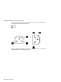
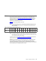
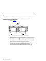
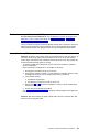
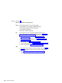
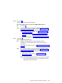
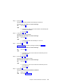
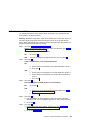
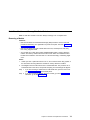
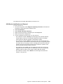
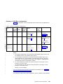
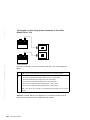
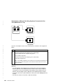
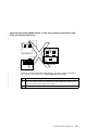
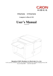
SCSI Bus Configurations and Addresses
The SCSI bus bridge card assigns the disk drive modules to a SCSI bus as determined
by the setting of the SCSI Bus Split switch that is on the switch card assembly. Three
SCSI bus modes are available:
v Single bus, one SCSI attachment (for example, a SCSI adapter in the using system):
SCSI address 7 is assigned to the SCSI attachment. The 2104 can have 14 disk
drive modules (SCSI addresses 0 through 6, and 8 through 14).
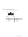
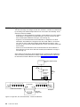
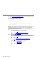
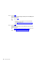
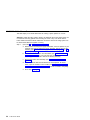
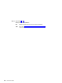
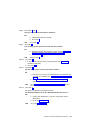
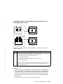
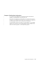
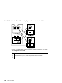
v Single bus, two SCSI attachments: SCSI addresses 5 is assigned to one SCSI
attachment; SCSI address 6 is assigned to the other. SCSI address 7 is reserved.
The 2104 can have 12 disk drive modules (SCSI addresses 0 through 4, and 8
through 14). The slots whose SCSI addresses are 5 and 6 must contain dummy disk
drive modules.
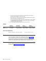
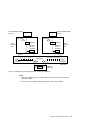
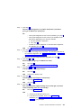
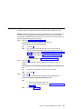
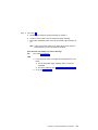
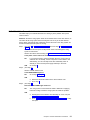
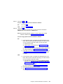
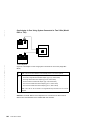
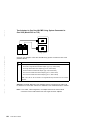
v Dual bus, two SCSI attachments: Each SCSI attachment has SCSI addresses 7.
Each SCSI bus can have seven disk drive modules (SCSI addresses 0 through 6,
and 8 through 14).
When single bus mode and two SCSI attachments are configured, SCSI addresses 5
and 6 are used by a SCSI attachment. Always install dummy disk drive modules into
the slots that have SCSI addresses 5 and 6 (see “SCSI Addresses” on page 25).
Host bus adapter (HBA)
ID:7
Terminator
Repeater
Enclosure
service
processor
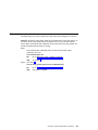
0 1 2 3 4 5 6
SCSI
interface
card
8 9 10 11 12 13 14
Terminators
Terminator
Terminator
14 disk drive modules
Backplane
Repeater
SCSI bus
bridge card
Figure 13. Single Bus, One SCSI Attachment, 14 Disk Drive Modules
26
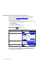
2104 Service Guide
Host bus adapter (HBA)
ID:5 or 6
Host bus adapter (HBA)
ID:6 or 5
Terminator
SCSI
interface
card
Terminator
Repeater
Repeater
Enclosure
service
processor
Enclosure
service
processor
0 1 2 3 4 X X
SCSI
interface
card
8 9 10 11 12 13 14
Terminators
Terminator
Terminator
12 disk drive modules
Backplane
Repeater
SCSI bus
bridge card
Figure 14. Single Bus, Two SCSI Attachments, 12 Disk Drive Modules
Notes:
1. Disk drive module slots 6 and 7 (SCSI addresses 5 and 6) must contain dummy
disk drive modules.
2. The two host bus adapters cannot both have the same SCSI address.
Chapter 1. Reference Information
27
Host bus adapter (HBA)
ID:7
Host bus adapter (HBA)
ID:7
Terminator
SCSI
interface
card
Terminator
Repeater
Repeater
Enclosure
service
processor
Enclosure
service
processor
0 1 2 3 4 5 6
SCSI
interface
card
8 9 10 11 12 13 14
Terminators
Terminator
Terminator
7 disk drive modules
7 disk drive modules
Repeater
Backplane
SCSI bus
bridge card
Figure 15. Dual Bus, Two SCSI Attachments, Seven Disk Drive Modules x 2
Microcode Maintenance
When a new level of SCSI interface card microcode or disk drive microcode becomes
available, that microcode and the appropriate installation instructions are put onto the
web support page (see “Web Support Page” in “Appendix A. Additional Information for
RISC Systems”). The supplied installation instructions ensure that the microcode is
downloaded to the correct location.
To update the 2104 vital product data (VPD) that is held in the using system, you might
need to reconfigure the 2104 to the using system. For more details, see “Configuring a
2104 to the Using System” in “Appendix A. Additional Information for RISC Systems”.
28
2104 Service Guide
Vital Product Data (VPD)
You can display the vital product data (VPD) for the 2104 by using the service aids.
This section shows the types of information that are contained in the VPD.
Abbreviations used in this section are:
FRU
Field-replaceable unit
RAM
Random-access memory
ROM
Read-only memory
ROS
Read-only storage
SCSI
Small computer systems interface
SCSI Disk Drives
Manufacturer
Manufacturer and plant code
Machine type and model
Type and model
Part number
Disk drive part number
ROS Level and ID
ROM and RAM code load part number
Serial number
Disk enclosure serial number
EC level
Disk enclosure engineering change level
FRU number
FRU part number
Device Specific Z0
Device Specific Z1
Device Specific Z2
Device Specific Z3
Device Specific Z5
Device Specific Z6
2104
Manufacturer
Manufacturer and plant code
Machine type and model
Type and model
ROS Level and ID
ROM code load part number
Device Specific (Z0)
Chapter 1. Reference Information
29
2104 Service Aids
Service aids are available for the 2104. For descriptions of those service aids, see
“System Service Aids” in “Appendix A. Additional Information for RISC Systems”.
2104 Enclosure Services
If the using system and the 2104 are both operating, you can use the ANSI SCSI
Enclosure Service (SES) to determine the status of the 2104.
Use the Receive Diagnostic Results command, and go to the enclosure status page
(page 02). That page shows the health status of the 2104, and the status of the
components of the 2104.
In the health status byte, the critical fault bit, if set, indicates that a component in the
2104 has failed.
In the fan element, power supply element, and enclosure services element status fields,
the fault bit, if set, indicates that a particular component has failed.
30
2104 Service Guide
Service Inspection Guide
This inspection guide helps you to identify possible unsafe conditions on 2104s. Each
2104 has the necessary safety items installed to protect users and service personnel
from injury. This guide addresses only those items. You should use your good
judgment, however, to identify possible safety hazards that are not covered by this
guide.
If any unsafe conditions are present, you must determine how serious the possible
hazard could be, and whether you should continue without first correcting the problem.
Consider the following conditions and the safety hazards they present:
v Electrical hazards (especially primary power): Primary voltage on the frame can
cause serious or lethal electrical shock.
v Mechanical hazards: Loose or missing items (for example, nuts and screws) can
cause serious injury.
Using the following inspection checklist as a guide, inspect the 2104 for unsafe
conditions. See, if necessary, any suitable safety publications.
Inspection Checklist
1. Remove all power from the 2104 (see “All Power” on page 71).
2. Check the frame for damage (loose, broken, or sharp edges).
3. Check the power cables and ensure that:
a. The third-wire ground connector is in good condition. Use a meter to check that
the third-wire ground continuity is 0.1 ohm or less between the external ground
pin and the frame ground.
b. The insulation is not worn or damaged.
4. Check for any obvious nonstandard changes. Use good judgment about the safety
of any such changes.
5. Check inside the 2104 for any obvious unsafe conditions, such as metal particles,
water or other fluids, or marks of overheating, fire, or smoke damage.
6. Check for worn, damaged, or pinched cables.
7. Ensure that the voltage specified on the product-information label matches the
specified voltage of the electrical power outlet. If necessary, verify the voltage.
8. Inspect the fan-and-power-supply assemblies, and check that the fasteners in the
cover of the power-supply unit (screws or rivets) have not been removed or
disturbed.
9. Before connecting the 2104 to the using system, check the grounding as described
in “Checking the Grounding of the 2104” on page 32.
Chapter 1. Reference Information
31
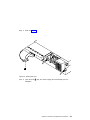
Checking the Grounding of the 2104
Go to the appropriate subsection for the 2104 that you are servicing.
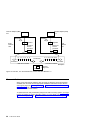
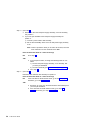
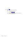
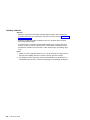
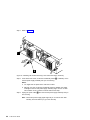
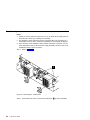
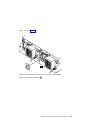
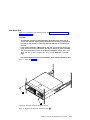
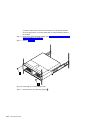
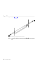
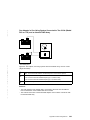
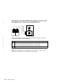
Grounding Check (2104 Model DU3)
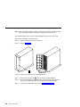
1. Refer to Figure 16.
Figure 16. Power Cables and SCSI Connectors (2104 Model DU3)
2. Ensure that all power is removed from the rack (see the Installation and Service
Guide, or equivalent, for the rack or using system).
3. Ensure that the power cables 1 are plugged into each fan-and-power-supply
assembly. Ensure also that the other ends of the power cables are plugged into
the power distribution unit or battery-backup unit in the rack (see the Installation
and Service Guide, or equivalent, for the rack or using system).
4. Attention: Some electrical circuits could be damaged if the external SCSI cables
are present at the 2104 while the grounding check is being done.
Ensure that no external SCSI cables are present at the connectors 2.
32
2104 Service Guide
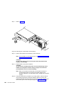
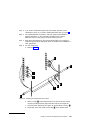
5. Follow your local procedures and check the grounding of the 2104. Any test
equipment must be connected to the frame of the 2104 3.
v If the grounding is correct (see step 3a on page 31), go no further with these
instructions.
v If the grounding is not correct, unplug the power cables from the
fan-and-power-supply assemblies in the 2104.
If you are servicing a 220-volt 2104, go to step 6.
If you are servicing a −48 volt 2104, go to step 9.
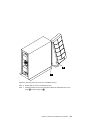
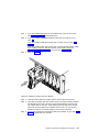
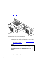
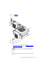
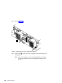
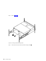
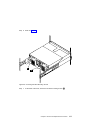
6. Refer to Figure 17.
Figure 17. Ground Pin (2104 Model DU3; 220 V)
7. Check for continuity between the frame of the 2104 and the ground pin 1 of
the power connector on each fan-and-power-supply assembly.
8. Go to step 12.
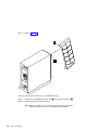
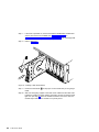
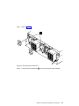
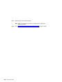
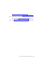
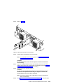
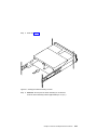
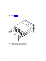
9. Refer to Figure 18.
Figure 18. Ground Pins (2104 Model DU3: −48 V)
10. Check for continuity between the frame of the 2104 and the ground pins 1 and 7
of each mainline-power connector.
11. Go to step 12.
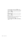
12. If any fan-and-power-supply assembly has no continuity, exchange that assembly
for a new one (see “Fan-and-Power-Supply Assemblies” on page 89), then do the
complete grounding check again.
Chapter 1. Reference Information
33
If each fan-and-power-supply assembly has continuity, you might have a problem
with the power cable or with the grounding of the using system.
If you are servicing a 220-volt 2104, go to step 13.
If you are servicing a −48 volt 2104, see the rack, or using-system, Installation and
Service Guide, or equivalent, to isolate the fault, then do the complete grounding
check again.
13. Check the power cable for continuity.
If the power cable does not have continuity, exchange it for a new one, then do the
complete grounding check again.
If the power cable does have continuity, see the rack, or using-system, Installation
and Service Guide, or equivalent, to isolate the fault.
34
2104 Service Guide
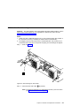
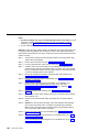
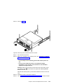
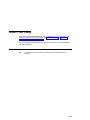
Grounding Check (2104 Model TU3)
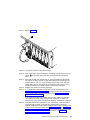
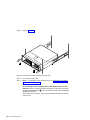
1. Refer to Figure 19.
Figure 19. Power Cables and SCSI Connectors (2104 Model TU3)
2. Ensure that a power cable is plugged into each power socket 1.
3. Ensure that the other ends of the power cables are not plugged into electrical
power outlets. Unplug the cables if necessary.
4. Attention: Some electrical circuits could be damaged if the external SCSI cables
are present at the 2104 while the grounding check is being done.
Ensure that no external SCSI cables are present at the SCSI connectors 2.
5. Check for continuity between the frame of the 2104 3 and the ground pin of
each power cable.
6. If the continuity is good (see step 3a on page 31), the grounding of the 2104 is
correct. Go no further with these instructions.
7. If the grounding is not correct, unplug the power cables from the mainline power
connectors. Then continue with step 8.
8. Check each power cable, for continuity.
Chapter 1. Reference Information
35
9. If either power cable is failing, exchange it for a new one, then go to step 10 .
10. Refer to Figure 20.
Figure 20. Ground Pin (2104 Model TU3)
11. Check for continuity between the frame of the 2104 and the ground pin 1 of
the power connector on each fan-and-power-supply assembly.
12. If either fan-and-power-supply assembly does not have continuity, exchange that
assembly for a new one (see “Fan-and-Power-Supply Assemblies” on page 89),
then do the complete grounding check again.
36
2104 Service Guide
Chapter 2. Problem Determination Procedures
Are You Using the Correct Book? Do not use this book if you are servicing a 2104
Model DL1 or TL1. For the correct book, see Related Publications in Appendix A.
Additional Information for RISC Systems.
Problem determination procedures are provided by power-on self-tests (POSTs), service
request numbers, and maintenance analysis procedures (MAPs). Some of these
procedures use the service aids that are described in the user or maintenance
information for your using-system SCSI attachment.
Disk Drive Module Power-On Self-Tests (POSTs)
The disk drive module POSTs start each time the module is switched on, or when a
Send Diagnostic command is received. They check whether the disk drive module is
working correctly. The POSTs also help verify a repair after a Field Replaceable Unit
(FRU) has been exchanged.
The tests are POST-1 and POST-2.
POST-1 runs immediately after the ‘power-on reset’ line goes inactive, and before the
disk drive module motor starts. POST-1 includes tests of:
v Microprocessor
v ROM
v Checking circuits.
If POST-1 completes successfully, POST-2 is enabled.
If POST-1 fails, the disk drive module is not configured into the system.
POST-2 runs after the disk drive module motor has started. POST-2 includes tests of:
v Motor control
v Servo control
v Read and write on the diagnostic cylinder (repeated for all heads)
v Error checking and correction (ECC).
If POST-2 completes successfully, the disk drive module is ready for use with the
system.
If POST-2 fails, the disk drive module is not configured into the system.
37
SCSI Interface Card Power-On Self-Tests (POSTs)
The SCSI interface card POSTs start each time power is switched on, or when a Reset
command is sent from the using-system SCSI attachment. They check only the internal
components of the SCSI interface card; they do not check any interfaces to other
FRUs.
If the POSTs complete successfully, control passes to the functional microcode of the
SCSI interface card. This microcode checks all the internal interfaces of the 2104, and
reports failures to the using system.
If the POSTs fail:
v The SCSI interface card Check light and the 2104 Check light come on.
v The functional operation of the 2104 is not affected. For example, the customer still
has access to all the disk drive modules.
v If a second SCSI interface card is present, it becomes the SES active card.
v The failure is reported:
– If the failure occurs at system bringup time, the using system might detect that the
2104 is missing, and reports an error.
– If the failure occurs at any time other than system bringup time, the hourly health
check reports the failure.
Service Request Numbers (SRNs)
Service request numbers (SRNs) are generated for the 2104 by diagnostics and the
SES healthcheck (see “Error Logging” on page 3). SRNs help you to identify the cause
of a problem, the FRUs, and the service actions that might be needed to solve the
problem.
The SRN Table
The table in this section lists the SRNs and describes the actions you should do. The
table columns are:
SRN
FRU list
Problem
38
2104 Service Guide
The service request number.
The FRU or FRUs that might be causing the problem (see also “FRU Names
Used in the SRN Table” on page 39), and how likely it is (by percentage) that
the FRU is causing the problem.
A description of the problem and the action you must take.
Using the SRN Table
Important: You should have been sent here from MAP 2010: 2104 – START. Do not
start problem determination from the SRN table; always go to “MAP 2010:
2104 – START” on page 44 first.
1. Locate the SRN in the table. If you cannot find a particular SRN in the table, go
to the SRN list that is in the user or maintenance information for your using-system
SCSI attachment. If you still cannot find the SRN, you have a problem with the
diagnostics, the microcode, or the documentation. Call your support center for
assistance.
2. Read carefully the “Action” you must do for the problem. Do not exchange FRUs
unless you are instructed to do so.
3. Unless instructed otherwise, exchange only one FRU at a time, starting from the
top of the FRU list for that SRN. Always use instructions given in “Chapter 3.
Removal and Replacement Procedures” when exchanging FRUs; a page reference
is given with each FRU in the FRU list. After each FRU is exchanged, go to “MAP
2410: 2104 – Repair Verification” on page 65 to verify the repair.
FRU Names Used in the SRN Table
This section provides a glossary of the FRU names used.
FRU Name in Table
Definition
Frame assembly
Disk drive module
The frame of the 2104 and the backplanes and cables that it contains.
A disk drive attached to a carrier that plugs into one of the backplanes of
the 2104.
A cable that connects the 2104 to a SCSI attachment or to another device
(for example, another 2104).
An assembly that consists of a power supply unit and a fan. The 2104 can
have two fan-and-power-supply assemblies, or one fan-and-power-supply
assembly and one fan assembly, whichever is suitable for the required
configuration.
An assembly that contains a dc cooling fan. The 2104 can have two
fan-and-power-supply assemblies, or one fan-and-power-supply assembly
and one fan assembly, whichever is suitable for the required configuration.
The card that monitors and controls the various functions of the 2104.
External SCSI cable
Fan-and-powersupply assembly
Fan assembly
SCSI interface card
assembly
SCSI attachment
Switch card
assembly
The means by which the 2104 is connected to the using system (for
example, a SCSI adapter card). The SCSI attachment is located in the
using system.
The assembly that contains all the option switches for the 2104.
Chapter 2. Problem Determination Procedures
39
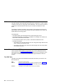
The SRNs
SRN
807-12X
FRU List
Problem
Fan-and-power-supply assembly
(90%) (“Fan-and-Power-Supply
Assemblies” on page 89)
Description: A power supply has failed. The diagnostic
message indicates the specific position of the failing FRU
(for example, Power Supply (n)).
SCSI interface card assembly (5%)
(“SCSI Interface Card Assembly” on
page 97)
Action: Exchange the FRU for a new FRU.
Frame assembly (5%) (“Frame
Assembly” on page 106)
807-13X
Fan assembly (90%) (“Fan Assembly”
on page 94)
SCSI interface card assembly (5%)
(“SCSI Interface Card Assembly” on
page 97)
Description: The fan assembly has failed. The diagnostic
message indicates the specific position of the failing FRU
(for example, Fan (n)).
Action: Exchange the FRU for a new FRU.
Frame assembly (5%) (“Frame
Assembly” on page 106)
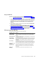
807-148
None
Description: Temperature warning.
Action: Take action to bring the ambient temperature inside
the specified limits (see “Environment” on page 23). If the
problem remains, exchange the SCSI interface card for a
new one (see “SCSI Interface Card Assembly” on page 97).
807-149
None
Description: Critical temperature warning.
Action: Take action to bring the ambient temperature inside
the specified limits (see “Environment” on page 23). If the
problem remains, exchange the SCSI interface card for a
new one (see “SCSI Interface Card Assembly” on page 97).
807-17X
SCSI interface card assembly (100%)
(“SCSI Interface Card Assembly” on
page 97)
Description: A SCSI interface card has failed. The diagnostic
message indicates the specific position of the failing FRU
(for example, Enclosure Services (n)).
Action: Exchange the FRU for a new FRU.
807-180
Switch card assembly (90%) (“Switch
Card Assembly” on page 102)
Description: Switch card assembly failure.
Action: Exchange the FRUs for new FRUs.
SCSI interface card assembly (5%)
(“SCSI Interface Card Assembly” on
page 97)
Frame assembly (5%) (“Frame
Assembly” on page 106)
40
2104 Service Guide
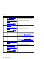
SRN
807-201
FRU List
Problem
SCSI interface card assembly (60%)
(“SCSI Interface Card Assembly” on
page 97)
Description: A device configuration error has occurred.
Action: Exchange the FRUs for new FRUs.
SCSI attachment (40%) (using-system
service information)
807-202
SCSI interface card assembly (60%)
(“SCSI Interface Card Assembly” on
page 97)
Description: The 2104 enclosure failed to open.
Action: Exchange the FRUs for new FRUs.
SCSI attachment (40%) (using-system
service information)
807-203
SCSI interface card assembly (60%)
(“SCSI Interface Card Assembly” on
page 97)
Description: The 2104 enclosure failed to return inquiry
data.
Action:
SCSI attachment (40%) (using-system
service information)
1. Observe the switch card assembly. Ensure that:
v Switch 3 (Enable Enclosure Services) is set to On.
v Switch 4 (Select Enclosure Services) is set to On.
2. Go to “MAP 2010: 2104 – START” on page 44.
3. If the problem remains, exchange the FRUs for new
FRUs.
807-204
Fan-and-power-supply assembly
(45%) (“Fan-and-Power-Supply
Assemblies” on page 89)
Fan assembly (45%) (“Fan Assembly”
on page 94)
Description: A 2104 has detected a noncritical enclosure
failure.
Action: Go to “MAP 2010: 2104 – START” on page 44. If the
problem remains, exchange the FRUs for new FRUs.
SCSI interface card assembly (4%)
(“SCSI Interface Card Assembly” on
page 97)
Switch card assembly (3%) (“Switch
Card Assembly” on page 102)
Frame assembly (3%) (“Frame
Assembly” on page 106)
Chapter 2. Problem Determination Procedures
41
SRN
807-205
FRU List
Problem
Fan-and-power-supply assembly
(45%) (“Fan-and-Power-Supply
Assemblies” on page 89)
Description: A 2104 has detected a critical enclosure failure.
Fan assembly (45%) (“Fan Assembly”
on page 94)
SCSI interface card assembly (4%)
(“SCSI Interface Card Assembly” on
page 97)
Switch card assembly (3%) (“Switch
Card Assembly” on page 102)
Frame assembly (3%) (“Frame
Assembly” on page 106)
42
2104 Service Guide
Action: Go to “MAP 2010: 2104 – START” on page 44. If the
problem remains, exchange the FRUs for new FRUs.
Maintenance Analysis Procedures (MAPs)
Are You Using the Correct Book? Do not use this book if you are servicing a 2104
Model DL1 or TL1. For the correct book, see Related Publications in Appendix A.
Additional Information for RISC Systems.
These maintenance analysis procedures (MAPs) describe how to analyze a continuous
failure that has occurred in a 2104 containing one or more SCSI disk drive modules.
Failing field-replaceable units (FRUs) of the 2104 can be isolated with these MAPs.
How to Use these MAPs
Attention: Unless the using system needs to be switched off for some other reason, do
not switch off the using system when servicing the 2104 or any of its SCSI devices.
Power cables and external SCSI cables that connect the 2104 to the using system can
be disconnected while that system is running.
v To isolate the FRUs in the failing 2104, do the actions and answer the questions
given in these MAPs.
v When instructed to exchange two or more FRUs in sequence:
1. Exchange the first FRU in the list for a new one.
2. Verify that the problem is solved. For some problems, verification means running
the diagnostic programs (see the using-system service procedures).
3. If the problem remains:
a. Reinstall the original FRU.
b. Exchange the next FRU in the list for a new one.
4. Repeat steps 2 and 3 until either the problem is solved, or all the related FRUs
have been exchanged.
5. Do the next action indicated by the MAP.
v See “Lights and Switches” on page 5 for locations and descriptions of the lights and
switches.
Attention: Disk drive modules are fragile. Handle them with care, and keep them well
away from strong magnetic fields.
Chapter 2. Problem Determination Procedures
43
MAP 2010: 2104 – START
This MAP is the entry point to the MAPs for the 2104. If you are not familiar with these
MAPs, read “How to Use these MAPs” on page 43 first.
You might have been directed here because:
v The system problem determination procedures sent you here.
v Action from an SRN list sent you here.
v A problem occurred during the installation of an 2104 or a disk drive module.
v Another MAP sent you here.
v A customer observed a problem that was not detected by the system problem
determination procedures.
Attention: Unless the using system needs to be switched off for some other reason, do
not switch off the using system when servicing the 2104 or any of its SCSI devices.
Power cables and external SCSI cables that connect the 2104 to the using system can
be disconnected while that system is running.
Step 1.
Does the 2104 emit smoke or a smell of burning?
NO
Go to step 2.
YES
Go to “MAP 2022: 2104 – Power-On” on page 52.
Step 2. (from steps 1 and 9 on page 45)
Are you at this MAP because power is not removed completely from the
2104 when the using systems are switched off?
NO
Go to step 3.
YES
Go to “MAP 2030: 2104 – Power Control” on page 57.
Step 3. (from step 2)
Have you been sent to this MAP from an SRN?
44
2104 Service Guide
NO
Go to step 4 on page 45.
YES
Go to step 7 on page 45.
Step 4. (from step 3)
Have the system diagnostics or problem determination procedures
given you an SRN for the 2104 (sesn)?
NO
v If the system diagnostics for the 2104 are available, go to step 5.
v If the system diagnostics for the 2104 are not available, but the
stand-alone diagnostics for the 2104 are available:
a. Run the stand-alone diagnostics.
b. Go to step 6.
v If neither the system diagnostics nor the stand-alone diagnostics
are available, go to step 7.
YES
Go to “Service Request Numbers (SRNs)” on page 38.
Step 5. (from step 4)
a. Run the concurrent diagnostics to the 2104. For information about how to
run concurrent diagnostics, see “Concurrent Diagnostics” in “Appendix A.
Additional Information for RISC Systems”.
b. When the concurrent diagnostics have completed, go to step 6.
Step 6. (from steps 4 and 5)
Did the diagnostics give you an SRN for the 2104?
NO
Go to step 7.
YES
Go to “Service Request Numbers (SRNs)” on page 38.
Step 7. (from steps 3, 4, and 6)
Is the Subsystem Check light flashing?
NO
Go to step 8.
YES
A device is in Identify mode.
Step 8. (from step 7)
Is the Subsystem Check light on continuously?
NO
Go to step 12 on page 47.
YES
Go to step 9.
Step 9. (from step 8)
Does a fan-and-power-supply assembly have its CHK light on because
its DC On/Standby switch is set to Standby?
NO
Go to step 10 on page 46.
YES
a. Set the DC On/Standby switch to On.
b. If you still have a problem, return to step 2 on page 44.
Otherwise, go to “MAP 2410: 2104 – Repair Verification” on
page 65 to verify the repair.
Chapter 2. Problem Determination Procedures
45
Step 10. (from step 9)
Does any FRU have its Check light on?
Note: The Check light might be on any of the following:
v A SCSI interface card assembly (CARD FAULT light)
v A fan-and-power-supply assembly (CHK light)
v A fan assembly (CHK light)
v A disk drive module (Check light)
NO
In the sequence shown, exchange the following FRUs for new
FRUs. Ensure that for each FRU exchange, you go to “MAP 2410:
2104 – Repair Verification” on page 65 to verify the repair.
a. SCSI interface card assembly (see “SCSI Interface Card
Assembly” on page 97)
b. Fan-and-power-supply assembly (see “Fan-and-Power-Supply
Assemblies” on page 89)
c. Fan assembly (see “Fan Assembly” on page 94)
d. Switch card assembly (see “Switch Card Assembly” on page 102)
e. Frame assembly (see “Frame Assembly” on page 106)
YES
a. If the FRU is a fan-and-power-supply assembly, go to step 11 on
page 47. Otherwise, exchange, for a new FRU, the FRU whose
Check light is on.
b. Go to “MAP 2410: 2104 – Repair Verification” on page 65 to
verify the repair.
46
2104 Service Guide
Step 11. (from step 10)
Is the enclosure set up for remote power control (that is, is the Power
Control switch of the switch card assembly set to Off)?
NO
a. Exchange, for a new one, the fan-and-power-supply whose CHK
light is on (see “Fan-and-Power-Supply Assemblies” on page 89).
b. Go to “MAP 2410: 2104 – Repair Verification” on page 65 to
verify the repair.
YES
a. Ensure that:
v The DC On/Standby switch is set to On.
v Both ends of the SCSI cable are correctly connected.
v The Power Control switch of the switch card assembly is set
to Off (see “Switch Card Assembly Switches” on page 9).
v The using system is switched on.
b. If the CHK light of the fan-and-power-supply assembly is still on,
pull out the fan-and-power-supply to disconnect it from the 2104,
then push it back to reseat its connectors (see
“Fan-and-Power-Supply Assemblies” on page 89).
c. If the CHK light is still on, exchange, in the sequence shown, the
following FRUs for new FRUs. Ensure that for each FRU
exchange, you go to “MAP 2410: 2104 – Repair Verification” on
page 65 to verify the repair.
1) Fan-and-power-supply assembly whose CHK light is on (see
“Fan-and-Power-Supply Assemblies” on page 89)
2) SCSI interface card (see “SCSI Interface Card Assembly” on
page 97)
3) Switch card assembly (see “Switch Card Assembly” on
page 102)
4) Frame assembly (see “Frame Assembly” on page 106)
Step 12. (from step 8)
Is the Subsystem Power light on?
NO
Go to “MAP 2020: 2104 – Power” on page 49.
YES
Go to step 13 on page 48.
Chapter 2. Problem Determination Procedures
47
Step 13. (from step 12)
Does either fan-and-power-supply assembly have its DC PWR light off
when it should be on?
NO
Go to step 14.
YES
a. Exchange, for a new assembly, the fan-and-power-supply
assembly whose light is off.
b. Go to “MAP 2410: 2104 – Repair Verification” on page 65 to
verify the repair.
Step 14. (from step 13)
Are you here because access to all the SCSI devices that are in the
2104 has been lost?
48
2104 Service Guide
NO
No problem has been found on the 2104. For a final check, go to
“MAP 2410: 2104 – Repair Verification” on page 65.
YES
Go to “MAP 2340: 2104 – SCSI Bus” on page 59.
MAP 2020: 2104 – Power
This MAP helps you to isolate FRUs that are causing a power problem on a 2104.
Attention: Unless the using system needs to be switched off for some other reason, do
not switch off the using system when servicing the 2104 or any of its SCSI devices.
Power cables and external SCSI cables that connect the 2104 to the using system can
be disconnected while that system is running.
Step 1. (from step 12 in MAP 2010: 2104 – START)
You are here because the Subsystem Power light is off.
Are any lights on at the front of the 2104?
NO
Go to step 2.
YES
The Subsystem Power light has failed. In the sequence shown,
exchange the following FRUs for new FRUs. Ensure that for each
FRU exchange, you go to “MAP 2410: 2104 – Repair Verification” on
page 65 to verify the repair.
a. SCSI interface card (see “SCSI Interface Card Assembly” on
page 97)
b. Frame assembly (see “Frame Assembly” on page 106)
Step 2. (from step 1)
Observe the fan-and-power-supply assembly (or assemblies, if two are
present).
Does at least one fan-and-power-supply assembly have its AC PWR light
on?
Step 3.
NO
Check the mainline power source and the power cable.
YES
Go to step 3.
(from step 2)
Observe the fan-and-power-supply assembly whose AC PWR light is on.
Is this fan-and-power-supply assembly switched on?
NO
a. Set the DC On/Standby switch to On.
b. If the problem is still not solved, go to “MAP 2010: 2104 – START”
on page 44.
YES
Go to step 4 on page 50.
Chapter 2. Problem Determination Procedures
49
Step 4. (from step 3)
Does the fan-and-power-supply assembly have its DC PWR light on?
NO
a. Set the DC On/Standby switch to Standby, then to On again.
b. Go to step 5.
YES
In the sequence shown, exchange the following FRUs for new FRUs.
Ensure that for each FRU exchange, you go to “MAP 2410: 2104 –
Repair Verification” on page 65 to verify the repair.
a. Fan-and-power-supply assembly (see “Fan-and-Power-Supply
Assemblies” on page 89).
b. Frame assembly (see “Frame Assembly” on page 106).
Step 5. (from step 4)
Does the fan-and-power-supply assembly have its DC PWR light on now?
Step 6.
NO
Go to step 6.
YES
If the problem is still not solved, go to “MAP 2010: 2104 – START” on
page 44.
(from step 5)
Observe the switch card assembly (see “Switch Card Assembly Switches” on
page 9).
Is the power control switch set to OFF?
NO
In the sequence shown, exchange the following FRUs for new FRUs.
Ensure that for each FRU exchange, you go to “MAP 2410: 2104 –
Repair Verification” on page 65 to verify the repair.
a. Fan-and-power-supply assembly (see “Fan-and-Power-Supply
Assemblies” on page 89)
b. SCSI interface card assembly (see “SCSI Interface Card
Assembly” on page 97)
c. Switch card assembly (see “Switch Card Assembly” on page 102)
YES
50
2104 Service Guide
Go to step 7 on page 51.
Step 7. (from step 6)
Observe the SCSI interface card assemblies.
Does either SCSI interface card have its TERM POWER light on?
NO
Go to step 8.
YES
In the sequence shown, exchange the following FRUs for new FRUs.
Ensure that for each FRU exchange, you go to “MAP 2410: 2104 –
Repair Verification” on page 65 to verify the repair.
a. Fan-and-power-supply assembly (see “Fan-and-Power-Supply
Assemblies” on page 89)
b. SCSI interface card (see “SCSI Interface Card Assembly” on
page 97)
c. Switch card assembly (see “Switch Card Assembly” on page 102)
Step 8.
(from step 7)
Is the using system switched on?
NO
Switch on the using system (see the using system-service
information). The 2104 should switch on when the using system
switches on.
If the problem is still not solved, go to “MAP 2010: 2104 – START” on
page 44.
YES
In the sequence shown, exchange the following FRUs for new FRUs.
Ensure that for each FRU exchange, you go to “MAP 2410: 2104 –
Repair Verification” on page 65 to verify the repair.
a. External SCSI cables
b. SCSI interface card assembly (see “SCSI Interface Card
Assembly” on page 97)
Note: If the TERM POWER light is still off, you might have a problem
with the SCSI attachment that is in the using system (see the
using-system service information).
Chapter 2. Problem Determination Procedures
51
MAP 2022: 2104 – Power-On
This MAP helps you to isolate FRUs that are causing a power problem on a 2104.
Attention: Unless the using system needs to be switched off for some other reason, do
not switch off the using system when servicing the 2104 or any of its SCSI devices.
Power cables and external SCSI cables that connect the 2104 to the using system can
be disconnected while that system is running.
Step 1. (from step 1 in MAP 2010: 2104 – START)
a. Remove both fan-and-power-supply assemblies, if two are present. If your
2104 has only one fan-and-power supply assembly, remove also the fan
assembly (see “Fan-and-Power-Supply Assemblies” on page 89 and “Fan
Assembly” on page 94).
b. Remove the SCSI interface card assemblies (see “SCSI Interface Card
Assembly” on page 97). If your 2104 has only one SCSI interface card
assembly, you do not need to remove the dummy assembly.
c. Remove the switch card assembly (see “Switch Card Assembly” on
page 102).
d. Disconnect all the disk drive modules from the backplane. To do this
action, open the handle on each module (see “Disk Drive Modules and
Dummy Disk Drive Modules” on page 75). You do not need to completely
remove the disk drive modules.
e. Go to step 2 on page 53.
52
2104 Service Guide
Step 2. (from step 1)
a. Reinstall a fan-and-power-supply assembly into position 1.
b. Connect a power cable to the fan-and-power-supply assembly.
c. Set the DC On/Standby switch of the fan-and-power-supply assembly to
On.
Note: Unless a procedure needs you to switch off the 2104, leave the
2104 switched on for the remainder of this MAP.
Does the 2104 emit smoke or a smell of burning?
NO
Go to step 3 on page 54.
YES
a. In the sequence shown, exchange the following FRUs for new
FRUs:
1) The fan-and-power-supply assembly that you have just
reinstalled
2) The frame assembly (see “Frame Assembly” on page 106)
b. Go to step 3 on page 54.
Chapter 2. Problem Determination Procedures
53
Step 3. (from step 2)
a. Reinstall the other fan-and-power-supply assembly, or the fan assembly,
into position 2.
b. If you have just reinstalled a fan-and-power-supply assembly into
position 2:
1) Connect a power cable to that assembly.
2) Set the DC On/Standby switch of the fan-and-power-supply assembly
to On.
Note: Unless a procedure needs you to switch off the 2104, leave the
2104 switched on for the remainder of this MAP.
Does the 2104 emit smoke or a smell of burning?
NO
Go to step 4.
YES
a. In the sequence shown, exchange the following FRUs for new
FRUs:
1) The fan-and-power-supply assembly, or fan assembly, that
you have just reinstalled
2) The frame assembly (see “Frame Assembly” on page 106)
b. Go to step 4.
Step 4. (from step 3)
Reinstall a SCSI interface card assembly into position 1.
Does the 2104 emit smoke or a smell of burning?
NO
If the 2104 has two SCSI interface cards, go to step 5 on page 55.
Otherwise, go to step 6 on page 55.
YES
a. Exchange, for a new one, the SCSI interface card assembly that
you have just reinstalled.
b. If the 2104 has two SCSI interface cards, go to step 5 on
page 55. Otherwise, go to step 6 on page 55.
54
2104 Service Guide
Step 5. (from step 4)
Reinstall the other SCSI interface card assembly into position 2.
Does the 2104 emit smoke or a smell of burning?
NO
Go to step 6.
YES
a. Exchange, for a new one, the SCSI interface card assembly that
you have just reinstalled.
b. Go to step 6.
Step 6.
(from steps 4 and 5)
Reinstall the switch card assembly.
Does the 2104 emit smoke or a smell of burning?
NO
Go to step 7.
YES
a. Exchange the switch card assembly for a new one.
b. Go to step 7.
Step 7. (from step 6)
Reconnect a disk drive module by closing its handle (see “Installing a
Module” on page 80).
Does the 2104 emit smoke or a smell of burning?
NO
Go to step 8.
YES
a. Exchange, for a new one, the disk drive module that you have
just reconnected.
b. Go to step 8.
Step 8. (from steps 7 and 9)
Reconnect the next disk drive module.
Does the 2104 emit smoke or a smell of burning?
NO
Go to step 9.
YES
a. Exchange, for a new one, the disk drive module that you have
just reconnected.
b. Go to step 9.
Step 9. (from step 8)
Have you reconnected all the disk drive modules?
NO
Return to step 8.
YES
Go to step 10 on page 56.
Chapter 2. Problem Determination Procedures
55
Step 10. (from steps 4 and 9)
Have you solved the problem?
56
2104 Service Guide
NO
Remove all power from the 2104, and call for assistance.
YES
Go to step “MAP 2410: 2104 – Repair Verification” on page 65 to
verify the repair.
MAP 2030: 2104 – Power Control
This MAP helps you to isolate FRUs that are causing a power problem when power
control is active.
Attention: Unless the using system needs to be switched off for some other reason, do
not switch off the using system when servicing the 2104 or any of its SCSI devices.
Power cables and external SCSI cables that connect the 2104 to the using system can
be disconnected while that system is running.
Step 1. (from step 2 in MAP 2010: 2104 – START, and from step 5 in MAP 2020: 2104
– Power)
You are here because power is still present at the 2104 although the using
system is switched off.
Observe the switch card assembly (see “Switch Card Assembly” on page 102).
Is the power control switch set to Off?
NO
If you want the 2104 to switch to Standby when the using system is
switched off or to Standby, set the 2104 power control switch to Off.
Alternatively, you can manually set the DC On/Standby switch to
Standby on each fan-and-power-supply assembly in the 2104.
YES
Go to step 2.
Step 2. (from step 1)
Observe a SCSI interface card.
Is the TERM POWER light on?
NO
Go to step 4 on page 58.
YES
a. Disconnect the SCSI cable from the SCSI interface card.
b. Go to step 3.
Step 3. (from step 2)
Does the TERM POWER light remain on?
NO
The using system to which the SCSI cable is attached is supplying
terminator voltage. Check the using system to isolate the problem.
YES
a. Exchange the SCSI interface card assembly for a new one (see
“SCSI Interface Card Assembly” on page 97).
b. Go to “MAP 2410: 2104 – Repair Verification” on page 65 to verify
the repair.
Chapter 2. Problem Determination Procedures
57
Step 4. (from step 2)
Does the 2104 have two fan-and-power-supply assemblies?
NO
a. In the sequence shown, exchange the following FRUs for new
FRUs:
1) Fan-and-power-supply assembly (see “Fan-and-Power-Supply
Assemblies” on page 89)
2) SCSI interface card assembly (see “SCSI Interface Card
Assembly” on page 97)
b. Go to step 7.
YES
Go to step 5.
Step 5. (from step 4)
Do both fan-and-power-supply assemblies have their DC PWR lights on?
NO
Go to step 6.
YES
In the sequence shown, exchange the following FRUs for new FRUs.
Ensure that for each FRU exchange, you go to “MAP 2410: 2104 –
Repair Verification” on page 65 to verify the repair.
a. SCSI interface card assembly (see “SCSI Interface Card
Assembly” on page 97)
b. Frame assembly (see “Frame Assembly” on page 106)
Step 6. (from step 5)
Does only one fan-and-power-supply assembly have its DC PWR light
on?
NO
Go to step 7.
YES
a. Exchange, for a new one, the fan-and-power-supply assembly
whose DC PWR light remains on (see “Fan-and-Power-Supply
Assemblies” on page 89).
b. Go to step 7.
Step 7. (from steps 4 and 6)
Is the 2104 still powered on?
58
2104 Service Guide
NO
The problem is solved.
YES
Call for assistance.
MAP 2340: 2104 – SCSI Bus
You are here because the using system cannot get access to any SCSI device (disk
drive module or enclosure services).
Attention: Unless the using system needs to be switched off for some other reason, do
not switch off the using system when servicing the 2104 or any of its SCSI devices.
Power cables and external SCSI cables that connect the 2104 to the using system can
be disconnected while that system is running.
Step 1. (from step 14 in MAP 2010: 2104 – START)
Observe the SCSI Bus Split switch on the switch card assembly (see “Switch
Card Assembly Switches” on page 9).
Is the SCSI Bus Split switch set to Off?
NO
Go to step 12.
YES
The 2104 is configured in single SCSI bus mode. Go to step 2.
Step 2. (from step 1)
Is the 2104 attached to a second SCSI attachment?
NO
a. Ensure that the SCSI address of the SCSI attachment is set to 7.
b. Go to step 3.
YES
a. Ensure that the SCSI address of one SCSI attachment is set to 7.
b. Ensure that the SCSI address of the second SCSI attachment is
set to 6.
c. Go to step 3.
Step 3. (from step 2)
Does the 2104 have two SCSI interface card assemblies?
NO
Go to step 4.
YES
a. Remove one of the SCSI interface card assemblies (see “SCSI
Interface Card Assembly” on page 97).
b. Go to step 4.
Step 4. (from step 3)
a. Note the positions of all the disk drive modules and dummy disk drive
modules so that you can reinstall the modules into their correct slots later.
b. Go to step 5.
Step 5. (from step 4)
a. Remove all the disk drive modules, except for one (see “Disk Drive
Modules and Dummy Disk Drive Modules” on page 75).
b. Go to step 6 on page 60.
Chapter 2. Problem Determination Procedures
59
Step 6. (from steps 5 and 8)
Can the using system access this disk drive module?
NO
Go to step 7.
YES
Go to step 8 on page 61.
Step 7. (from step 6)
Remove the disk drive module that you have just tested, and install a different
disk drive module into a different slot.
Note: Because this disk drive module is not in the same slot, its SCSI address
is different (see “SCSI Addresses” on page 25).
Can the using system access this disk drive module?
NO
a. In the sequence shown, exchange the following FRUs for new
FRUs. Ensure that for each FRU exchange, you check whether
you can access the disk drive module, to verify the repair.
1) External SCSI cable
2) SCSI interface card assembly (see “SCSI Interface Card
Assembly” on page 97)
3) SCSI attachment (see the using-system service information)
4) Frame assembly (see “Frame Assembly” on page 106)
b. If the repair is successful, reinstall all the disk drive modules and,
if removed in step 3 on page 59, the SCSI interface card
assembly.
c. Go to “MAP 2410: 2104 – Repair Verification” on page 65 to verify
the repair.
YES
a. In the sequence shown, exchange the following FRUs for new
FRUs. Ensure that for each FRU exchange, you check whether
you can access the disk drive module.
1) The disk drive module that you tested immediately before
this one (see “Disk Drive Modules and Dummy Disk Drive
Modules” on page 75). Install the replacement disk drive
module into the original slot.
2) Frame assembly (see “Frame Assembly” on page 106)
b. Reinstall all the other disk drive modules and, if removed in step 3
on page 59, the SCSI interface card assembly.
c. Go to “MAP 2410: 2104 – Repair Verification” on page 65 to verify
the repair.
60
2104 Service Guide
Step 8. (from steps 6 and 9)
Have you reinstalled all the disk drive modules?
NO
a. Install another disk drive module.
b. Go to step 9.
YES
Go to step 10.
Step 9. (from step 8)
Can the using system get access to this disk drive module?
NO
a. Exchange the disk drive module for a new one (see “Disk Drive
Modules and Dummy Disk Drive Modules” on page 75).
b. Return to step 8.
YES
Return to step 8.
Step 10. (from step 8)
a. If you removed a SCSI interface card assembly in step 3 on page 59,
reinstall that assembly.
b. Go to step 11.
Step 11. (from step 10)
Can the using system access any disk drive module?
NO
a. Exchange, for a new one, the SCSI interface card assembly that
you have just reinstalled (see “SCSI Interface Card Assembly” on
page 97).
b. Go to “MAP 2410: 2104 – Repair Verification” on page 65 to
verify the repair.
YES
Go to “MAP 2410: 2104 – Repair Verification” on page 65 to verify
the repair.
Step 12. (from step 1)
The 2104 is configured in dual SCSI bus mode.
Are the SCSI addresses of the two SCSI attachments both set to 7?
NO
a. Set the SCSI addresses to 7 (see the using-system service
information).
b. Go to step 13 on page 62.
YES
Go to step 13 on page 62.
Chapter 2. Problem Determination Procedures
61
Step 13. (from step 12)
Have the using systems lost access both to the disk drive modules that
are in the SCSI address range 0 through 6, and to the disk drive
modules that are in the SCSI address range 8 through 14?
NO
Go to step 14.
YES
In the sequence shown, exchange the following FRUs for new
FRUs. Ensure that for each FRU exchange, you go to “MAP 2410:
2104 – Repair Verification” on page 65.
a. SCSI bus bridge card assembly (see “SCSI Bus Bridge Card
Assembly” on page 85)
b. Switch card assembly (see “Switch Card Assembly” on page 102)
c. Frame assembly (see “Frame Assembly” on page 106)
Step 14. (from step 13)
Do the disk drive modules that the using system cannot access have
SCSI addresses in the range 0 through 6?
NO
Go to step 15.
YES
Go to step 16.
Step 15. (from step 14)
Observe the SCSI Address switch on the switch card assembly (see “Switch
Card Assembly Switches” on page 9).
Is the SCSI Address switch set to On?
NO
The switch is set for normal SCSI addresses.
a. Remove all devices, except for one, from slots 8 through 14.
b. Go to step 17 on page 63.
YES
The switch is set for reversed SCSI addresses.
a. Remove all the disk drive modules, except for one, from slots 1
through 7.
b. Go to step 17 on page 63.
Step 16. (from step 14)
Observe the SCSI Address switch on the switch card assembly (see “Switch
Card Assembly Switches” on page 9).
Is the SCSI Address switch set to On?
NO
The switch is set for normal SCSI addresses.
a. Remove all the disk drive modules, except for one, from slots 1
through 7.
b. Go to step 17 on page 63.
YES
The switch is set for reversed SCSI addresses.
a. Remove all the disk drive modules, except for one, from slots 8
through 14.
b. Go to step 17 on page 63.
62
2104 Service Guide
Step 17. (from steps 15 and 16)
Can the using system access this disk drive module?
Step 18.
NO
Go to step 18.
YES
Go to step 19 on page 64.
(from step 17)
Remove the disk drive module that you have just tested, and install a
different disk drive module into a different slot.
Note: Because this disk drive module is not in the same slot, its SCSI
address is different (see “SCSI Addresses” on page 25).
Can the using system access this disk drive module?
NO
a. In the sequence shown, exchange the following FRUs for new
FRUs. Ensure that for each FRU exchange, you check whether
you can access the disk drive module, to verify the repair.
1) External SCSI cable
2) SCSI interface card assembly (see “SCSI Interface Card
Assembly” on page 97)
3) SCSI attachment (see the using-system service information)
4) Frame assembly (see “Frame Assembly” on page 106)
b. If the repair is successful, reinstall all the disk drive modules, go
to “MAP 2410: 2104 – Repair Verification” on page 65 to verify
the repair.
YES
a. In the sequence shown, exchange the following FRUs for new
FRUs. Ensure that for each FRU exchange, you check whether
you can access the disk drive module.
1) The disk drive module that you tested immediately before
this one (see “Disk Drive Modules and Dummy Disk Drive
Modules” on page 75). Install the replacement disk drive
module into the original slot.
2) Frame assembly (see “Frame Assembly” on page 106)
b. Reinstall all the other disk drive modules.
c. Go to “MAP 2410: 2104 – Repair Verification” on page 65 to
verify the repair.
Chapter 2. Problem Determination Procedures
63
Step 19. (from step 17)
Have you reinstalled all the disk drive modules?
NO
a. Install another disk drive module.
b. Go to step 17 on page 63.
YES
64
2104 Service Guide
No fault has been found. You have probably solved the problem by
reconnecting the disk drive modules.
MAP 2410: 2104 – Repair Verification
This MAP helps you to verify a repair after a FRU has been exchanged for a new one.
Attention: Unless the using system needs to be switched off for some other reason, do
not switch off the using system when servicing the 2104 or any of its SCSI devices.
Power cables and external SCSI cables that connect the 2104 to the using system can
be disconnected while that system is running.
Step 1.
Ensure that the DC On/Standby switch of each fan-and-power-supply
assembly is set to On.
Are all Check lights off?
NO
Go to “MAP 2010: 2104 – START” on page 44.
YES
Go to step 2.
Step 2. (from step 1)
Can the using system get access to all SCSI devices?
NO
Go to “MAP 2010: 2104 – START” on page 44.
YES
The repair is complete.
Chapter 2. Problem Determination Procedures
65
66
2104 Service Guide
Chapter 3. Removal and Replacement Procedures
Are You Using the Correct Book? Do not use this book if you are servicing a 2104
Model DL1 or TL1. For the correct book, see Related Publications in Appendix A.
Additional Information for RISC Systems.
These instructions describe how to remove field-replaceable units (FRUs) from the
2104.
Each FRU has its own removal procedure, for example, “Fan-and-Power-Supply
Assembly”. Where a step in a specific procedure represents a complete procedure that
is described separately, a reference to that procedure is given. For example:
1. Remove the front cover (see “Cover” on page 68).
2. Remove all the disk drive modules (see “Removing a Module” on page 75).
The references show you where to find more detail, if you need it.
Note: Although these instructions relate to the 2104 Model DU3 and to the 2104 Model
TU3, some diagrams might not specifically show the model that you are
servicing.
Concurrent Maintenance
Subject to the configuration of the 2104, most FRUs can be removed, replaced, and
tested while the subsystem and using system are powered on and doing productive
work. This ability is called “concurrent maintenance”. Unless you have a particular
reason to do so, do not remove the power unless these instructions tell you to do so.
The following FRUs can be maintained concurrently in a 2104 subsystem:
v Fan assembly
v Fan-and-power-supply assembly (if two are present)
v Disk drive module
v Dummy disk drive module
v SCSI Interface card assembly (if the subsystem configuration allows)
v Dummy SCSI Interface card assembly
v Switch card assembly
v External SCSI cables (if the subsystem configuration allows)
The following FRUs cannot be maintained concurrently:
v SCSI bus bridge card assembly
v Frame assembly
67
Cover
Note: Unless you have a particular reason to do so, do not switch off the using system
or the 2104 when removing, opening or closing the cover of the 2104.
The 2104 Model DU3 has no covers. The 2104 Model TU3 has only a front cover.
To open and, if required, remove the cover:
Step 1. Ask the customer for the key to the cover.
Step 2. Refer to Figure 21.
Figure 21. Opening the Front Cover of a 2104 Model TU3
Step 3. Insert the key into the lock 1, and turn the key counterclockwise.
Step 4. The cover is pivoted on its left-hand side, and is held closed by clips. Pull
strongly on the right-hand side of the cover to release it from the clips.
Step 5. If you want to remove the cover, refer to Figure 22 on page 69.
68
2104 Service Guide
Figure 22. Removing the Front Cover of a 2104 Model TU3 (1)
Step 6. Ensure that the cover is unlocked and open.
Step 7. Grasp the bottom of the cover and pull it outward to release the lower cover
hinge 2 from the hinge pin 1.
Chapter 3. Removal and Replacement Procedures
69
Step 8. Refer to Figure 23.
Figure 23. Removing the Front Cover of a 2104 Model TU3 (2)
Step 9. Lift the cover to disengage the pivot hole 2 from the upper hinge pin 1.
Step 10. Replace parts in the reverse sequence.
Note: Before you install the cover, ensure that the lock is in the unlocked
position. Otherwise, the front cover might become damaged.
70
2104 Service Guide
All Power
Note: Unless you have a particular reason to do so, do not remove power from the
using system or from the 2104 unless the instructions that you are following tell
you to.
This section has two parts:
v “Power (2104 Model DU3)”
v “Power (2104 Model TU3)” on page 73.
Go to the part that is relevant to the Model of 2104 that you are servicing.
Power (2104 Model DU3)
Step 1. Verify with the customer that all operations between the 2104 and the using
system have been stopped.
Step 2. Refer to Figure 24.
Figure 24. Removing the Power from a 2104 Model DU3
Step 3. Set the DC On/Standby switch 1 of each fan-and-power-supply assembly to
Standby.
Notes:
a. Some 2104s have a fan-and-power-supply assembly and a fan assembly.
The fan assembly has no DC On/Standby switch.
b. A fan-and-power-supply assembly might have its CHK light on although its
DC On/Standby switch is set to On.
Chapter 3. Removal and Replacement Procedures
71
Note: For a translation of the following notice, see “Appendix D. Translated Safety
Notices” on page 167.
DANGER
In the following step you are going to remove the power cables. These cables
are live if the rack power distribution unit or uninterruptible power supply
(UPS) unit is still switched on.
Step 4. Remove the power cables 2 from the back of the 2104.
Step 5. To return power to the 2104:
a. Reinstall the power cables 2.
b. Set the DC On/Standby switch 1 of each fan-and-power-supply assembly
to On.
Note: You can configure the motor-start sequencing of the 2104 Models DU3
and TU3. For more information, see “Drive Autostart switch” on page 10
and “Delay Motor Start Mode switch” on page 10.
72
2104 Service Guide
Power (2104 Model TU3)
Step 1. Verify with the customer that all operations between the 2104 and the using
system have been stopped.
Step 2. Refer to Figure 25.
Figure 25. Removing Power from a 2104 Model TU3
Step 3. At the back of the 2104, set the DC On/Standby switch 1 of each
fan-and-power-supply assembly to Standby.
Notes:
a. Some 2104s have a fan-and-power-supply assembly and a fan assembly.
The fan assembly has no DC On/Standby switch.
b. A fan-and-power-supply assembly might have its CHK light on although its
DC On/Standby switch is set to On.
Step 4. Remove the power cables 2 from the electrical power outlet and from the
back of the 2104.
Step 5. To return power to the 2104:
a. Reinstall the power cables 2.
Chapter 3. Removal and Replacement Procedures
73
b. Set the DC On/Standby switch 1 of each fan-and-power-supply assembly
to On.
Note: You can configure the motor-start sequencing of the 2104 Models DU3
and TU3. For more information, see “Drive Autostart switch” on page 10
and “Delay Motor Start Mode switch” on page 10.
74
2104 Service Guide
Disk Drive Modules and Dummy Disk Drive Modules
Note: A disk drive module is one FRU. Always exchange it as a complete FRU.
Removing a Module
Attention:
v Disk drive modules are electrostatic-discharge (ESD) sensitive. Use the tools and
procedures defined by your organization to protect such parts. See also “Electrostatic
Discharge” on page xi.
v Disk drive modules are fragile. Handle them with care, and keep them well away
from strong magnetic fields.
v Any slot that has no disk drive module installed must contain a dummy disk drive
module. The dummy module ensures that the correct airflow is maintained around
the disk drive modules in the other slots. If a slot remains empty, overheating might
occur.
Notes:
1. Unless you have a particular reason to do so, do not switch off the using system or
the 2104 when removing disk drive modules or dummy disk drive modules.
2. The diagrams in these instructions show a 2104 Model DU3. The procedure for a
2104 Model TU3 is the same, except that everything is turned through 90 degrees.
Step 1. If you are removing a module from a 2104 Model TU3, open the front cover
(see “Cover” on page 68), if not already done.
Step 2. If you are removing a dummy disk drive module, go to step 3 on page 76.
Otherwise, go to step 7 on page 77.
Chapter 3. Removal and Replacement Procedures
75
Step 3. Refer to Figure 26.
Figure 26. Removing a Dummy Disk Drive Module
Step 4. Using the finger slot that is provided at the top of the module, remove the
dummy disk drive module.
Step 5. Lay the dummy disk drive module on its side in a safe place.
Step 6. Go to “Installing a Module” on page 80, and install a disk drive module.
76
2104 Service Guide
Step 7. Ensure that the using system is not using the disk drive module that you are
going to remove.
Step 8. Find the disk drive module that you are going to remove (see “SCSI
Addresses” on page 25.)
Step 9. If the 2104 is powered on, use the SCSI Device Identification and Removal
service aid to set the disk drive module to Remove (see “System Service
Aids” in “Appendix A. Additional Information for RISC Systems”). The Check
light of the disk drive module that you are going to remove comes on and
remains on.
Note: If the failing disk drive module is affecting the SCSI bus operation, the
service aid might not work correctly.
Step 10. Refer to Figure 27.
Figure 27. Opening the Handle of a Disk Drive Module
Step 11. On the disk drive module whose Check light is on (see step 9), press the blue
latch 1, and lift the handle 2 fully. This action pulls the module partially
out of its slot.
Step 12. Wait for approximately 20 seconds to allow the disk drive module to stop.
Chapter 3. Removal and Replacement Procedures
77
Step 13. Refer to Figure 28.
Figure 28. Removing a Disk Drive Module
Step 14. Grip the handle, and carefully pull out the disk drive module. As the module
comes out, put one hand under its base to prevent it from falling.
Step 15. Refer to Figure 29.
Figure 29. Placing a Disk Drive Module into a Safe Position
Step 16. Lay down the module as shown. In this position, the module rests on four
supports (not visible in Figure 29).
78
2104 Service Guide
Step 17. Attention: Any slot that has no disk drive module installed must contain a
dummy disk drive module. The dummy module ensures that the correct
airflow is maintained around the disk drive modules in the other slots. If a slot
remains empty, overheating might occur.
Go to “Installing a Module” on page 80, and install a disk drive module or a
dummy disk drive module, as required.
Chapter 3. Removal and Replacement Procedures
79
Installing a Module
Attention:
v Disk drive modules are electrostatic-discharge (ESD) sensitive. Use the tools and
procedures defined by your organization to protect such parts. See also “Electrostatic
Discharge” on page xi.
v Disk drive modules are fragile. Handle them with care, and keep them well away
from strong magnetic fields.
v Any slot that has no disk drive module installed must contain a dummy disk drive
module. The dummy module ensures that the correct airflow is maintained around
the disk drive modules in the other slots. If a slot remains empty, overheating might
occur.
Notes:
1. Unless you have a particular reason to do so, do not switch off the using system or
the 2104 when installing disk drive modules or dummy disk drive modules.
2. The diagrams in these instructions show a 2104 Model DU3. The procedure for a
2104 Model TU3 is the same, except that everything is turned through 90 degrees.
80
2104 Service Guide
Step 1. If you are installing a module into a 2104 Model TU3, open the front cover
(see “Cover” on page 68), if not already done.
Step 2. If you are installing a dummy disk drive module into an empty slot, go to
step 3.
If you are installing a disk drive module into an empty slot, go to step 7 on
page 82.
If you are installing a disk drive module into a slot that already contains a disk
drive module or a dummy disk drive module, remove that module (see
“Removing a Module” on page 75), then go to step 7 on page 82.
Step 3. Refer to Figure 30.
Figure 30. Installing a Dummy Disk Drive Module
Step 4. Insert the dummy disk drive module into the slot and push it fully home.
Step 5. Verify that the dummy disk drive module that you have just installed is aligned
with the sides of the 2104, and that no gap exists between this module and
the modules that are next to it. Verify also that the front edge of this module
aligns with the front edges of the modules that are next to it. If the dummy
disk drive module is not correctly aligned, remove it then reinstall it.
Step 6. Repeat this procedure for other dummy disk drive modules, or go to step 7 on
page 82 to install disk drive modules.
Chapter 3. Removal and Replacement Procedures
81
Step 7. If the 2104 is powered on, use the SCSI Device Identification and Removal
service aid to set the slot to Insert (see “System Service Aids” in
“Appendix A. Additional Information for RISC Systems”). The Check light that
is at the back of the slot (on the backplane) comes on.
Step 8. Refer to Figure 31.
Figure 31. Installing a Disk Drive Module
Step 9. Ensure that the handle 1 is fully open on the module that you are going to
install.
Step 10. With one hand giving support to the base of the module and the other hand
holding the handle, insert the module, and push it into the slot whose Check
light is on (see step 7). When the handle touches the front of the 2104, the
module stops. Note that the module is not yet fully home.
82
2104 Service Guide
Step 11. Refer to Figure 32
Figure 32. Closing the Handle of a Disk Drive Module
Step 12. While continuing to push the disk drive module into the slot, slowly close the
handle 1 until it stops with a click. This action pushes the module fully
home.
Step 13. Verify that the disk drive module that you have just installed is aligned with
the sides of the 2104, and that no gap exists between this module and the
modules that are next to it. Verify also that the front edge of this disk drive
module aligns with the front edges of the modules that are next to it. If the
disk drive module is not correctly aligned, remove it then reinstall it.
Step 14. Replace other parts in the reverse sequence.
Step 15. If you installed the disk drive module under concurrent maintenance (see
“Concurrent Maintenance” on page 67), configure the new disk drive module
to your using system. For more information, see “Appendix A. Additional
Information for RISC Systems”.
If you installed the disk drive module while the using system was switched
off, switch on the using system when you are ready to do so. When you
switch on the using system, the disk drive module is automatically configured.
Step 16. Using the method that is provided on your using system, check the level of
microcode that is present on the disk drive module that you have just
installed. Additional information about the latest levels of disk drive microcode
is given on the web support page (see “Web Support Page” in “Appendix A.
Additional Information for RISC Systems”). If you need to download the latest
microcode, see “Disk Drive Microcode Maintenance” in “Appendix A.
Additional Information for RISC Systems”.
Chapter 3. Removal and Replacement Procedures
83
Step 17. If the 2104 is attached to a RISC system, go to step 18. Otherwise, go to
step 19.
Step 18. The disk drive that you have just installed has been configured with new
hdisk numbers. If you want to change those numbers, go to “Configuring a
Disk Drive Module to the Using System” in “Appendix A. Additional
Information for RISC Systems”. Otherwise, go to step 19.
Step 19. If you came to this section from a step in MAP, return to that step, and
continue with the MAP. Otherwise, go to “MAP 2410: 2104 – Repair
Verification” on page 65 to verify the repair.
84
2104 Service Guide
SCSI Bus Bridge Card Assembly
Attention: Before you remove the SCSI bus bridge card assembly, switch off the using
systems.
Removing the SCSI Bus Bridge Card Assembly
Step 1. Ensure that the using systems have been switched off.
Step 2. Remove the two modules that are directly on each side of the SCSI bus bridge
card assembly (see “Removing a Module” on page 75).
Step 3. Refer to Figure 33.
1
2
Figure 33. Removing the SCSI Bridge Card Assembly Cover
Step 4. Squeeze each of the four lugs on the cover 1, then remove the cover.
Step 5. Lift the handle 2 of the SCSI bridge card assembly fully.
Chapter 3. Removal and Replacement Procedures
85
Step 6. Refer to Figure 34.
Figure 34. Removing the SCSI Bridge Card Assembly
Step 7. Grasp the assembly, and pull it out from the 2104.
86
2104 Service Guide
Installing the SCSI Bus Bridge Card Assembly
Step 1. Refer to Figure 35.
1
Figure 35. Installing the SCSI Bridge Card Assembly
Step 2. Ensure that the handle 1 of the SCSI bus bridge card assembly is fully open.
Step 3. Insert the SCSI bus bridge card assembly, and push it into the slot. When the
handle touches the front of the 2104, the assembly stops. Note that the
assembly is not yet fully home.
Chapter 3. Removal and Replacement Procedures
87
Step 4. Refer to Figure 36.
2
1
Figure 36. Closing the Handle and Installing the Cover
Step 5. Close the handle 1 until it stops with a click. This action pushes the SCSI
bus bridge card assembly fully home.
Step 6. Install the cover 2. Squeeze each of the four lugs to lock the cover in
position.
Step 7. Reinstall the disk drive modules that you removed earlier (see “Installing a
Module” on page 80).
88
2104 Service Guide
Fan-and-Power-Supply Assemblies
Notes:
1. Unless you have a particular reason to do so, do not switch off the using system or
the 2104 when removing or installing power supply assemblies.
2. The diagrams in these instructions show a 2104 Model DU3. The procedure for a
2104 Model TU3 is the same, except that everything is turned through 90 degrees.
3. A fan-and-power-supply assembly can be installed in either position at the back of
the 2104. You can easily distinguish it from a fan assembly, because it has a DC
On/Standby switch and a power connector.
4. The CHK light is valid only when the DC On/Standby switch is set to On. The light
is always on when the DC On/Standby switch is set to Standby.
5. If you are exchanging the fan-and-power-supply assembly of a unit that has one
fan-and-power-supply assembly and a fan assembly, do the following:
a. Remove the fan assembly (see “Fan Assembly” on page 94).
b. Install the replacement fan-and-power-supply assembly into the slot that
contained the fan assembly.
c. Remove the failing fan-and-power-supply assembly.
d. Install the fan assembly into the slot that contained the failing
fan-and-power-supply assembly.
Chapter 3. Removal and Replacement Procedures
89
Step 1. Refer to Figure 37.
Figure 37. Switching Off and Disconnecting a Fan-and-Power-Supply Assembly
Step 2. At the back of the 2104, set the DC On/Standby switch 1 to Standby on the
fan-and-power-supply assembly that you are removing.
Notes:
a. You might hear the speed of the other fan increase.
b. Although you have set the DC On/Standby switch to Standby, the amber
CHK light on the fan-and-power-supply assembly might come on or flash.
This condition is not a problem. Continue with the next step.
Step 3. Unplug the power cable 2 from the fan-and-power-supply assembly that you
are removing.
Note: The fan-and-power-supply lights might stay on for a short time. Wait
until they are all off before you go to the next step.
90
2104 Service Guide
Step 4. Refer to Figure 38.
Figure 38. Unscrewing the Thumbscrews
Step 5. Unscrew the two thumbscrews 1 on the fan-and-power-supply assembly.
Chapter 3. Removal and Replacement Procedures
91
Step 6. Refer to Figure 39.
Figure 39. Removing a Fan-and-Power-Supply Assembly
Step 7. Remove the fan-and-power-supply assembly.
The fan-and-power-supply assembly is a complete FRU. Do not try to repair or
exchange any part of it.
Note: For a translation of the following notices, see “Appendix D. Translated
Safety Notices” on page 167.
DANGER
Do not try to open the covers of the fan-and-power-supply assembly.
Do not plug a power cable into the fan-and-power-supply assembly
until the assembly is fully home and its thumbscrews are fully
tightened.
CAUTION:
Do not insert hands or tools into the space that contained the
fan-and-power-supply assembly.
92
2104 Service Guide
Step 8. Replace parts in the reverse sequence.
Notes:
a. When you insert the fan-and-power-supply assembly, you might hear the
speed of the other fan decrease.
Note: Remember to set the DC On/Standby switch to On after you have
reinstalled the fan-and-power-supply assembly. If the DC On/Standby
switch is already set to On when you reinstall the fan-and-power-supply
assembly, the CHK light might come on. If it does, set the DC
On/Standby switch to Standby, then to On.
Step 9. Go to “MAP 2410: 2104 – Repair Verification” on page 65 to verify the repair.
Chapter 3. Removal and Replacement Procedures
93
Fan Assembly
Notes:
1. Unless you have a particular reason to do so, do not switch off the using system or
the 2104 when removing or installing a fan assembly.
2. The diagrams in these instructions show a 2104 Model DU3. The procedure for a
2104 Model TU3 is the same, except that everything is turned through 90 degrees.
3. A fan assembly can be installed in either position at the back of the 2104. You can
easily distinguish it from the fan-and-power-supply assembly, because it has no DC
On/Standby switch or power connector.
Step 1. Refer to Figure 40.
Figure 40. Unscrewing the Thumbscrews
Step 2. At the back of the 2104, unscrew the thumbscrews 1 of the fan assembly.
94
2104 Service Guide
Step 3. Refer to Figure 41.
Figure 41. Removing a Fan Assembly
Step 4. Pull out the assembly.
Notes:
a. You might hear the speed of the other fan increase.
b. For a translation of the following notice, see “Appendix D. Translated
Safety Notices” on page 167.
CAUTION:
Do not insert hands or tools into the space that contained the fan
assembly.
Note:
The fan assembly is a complete FRU. Do not try to repair or exchange any
part of it.
Chapter 3. Removal and Replacement Procedures
95
Step 5. Replace parts in the reverse sequence.
Note: When you insert the fan assembly, you might hear the speed of the
other fan decrease.
Step 6. Go to “MAP 2410: 2104 – Repair Verification” on page 65 to verify the repair.
96
2104 Service Guide
SCSI Interface Card Assembly
Attention: The SCSI interface card is electrostatic-discharge (ESD) sensitive. Use the
tools and procedures defined by your organization to protect such parts. See also
“Electrostatic Discharge” on page xi.
Notes:
1. Unless you have a particular reason to do so, do not switch off the using system or
the 2104 when removing or installing the SCSI interface card assembly.
2. The diagrams in these instructions show a 2104 Model DU3. The procedure for a
2104 Model TU3 is the same, except that everything is turned through 90 degrees.
Step 1. Refer to Figure 42
Figure 42. Disconnecting the SCSI Cable
Step 2. Disconnect the SCSI cable 1 (if present).
Note: If the 2104 is switched on, it might switch off when you do this action
(see “Power Control switch” on page 10).
Chapter 3. Removal and Replacement Procedures
97
Step 3. Refer to Figure 43.
1
Figure 43. Unscrewing the Thumbscrew
Step 4. Unscrew the thumbscrew 1.
98
2104 Service Guide
Step 5. Refer to Figure 44.
Figure 44. Opening the Lever
Step 6. Open the lever 1 fully. This action unplugs the card assembly from the
backplane.
Chapter 3. Removal and Replacement Procedures
99
Step 7. Refer to Figure 45.
Figure 45. Removing the SCSI Interface Card Assembly
Step 8. Pull the SCSI interface card assembly out from the 2104.
Note: For a translation of the following notice, see “Appendix D. Translated
Safety Notices” on page 167.
CAUTION:
Do not insert hands or tools into the space that contained the SCSI
interface card assembly.
Step 9. Replace parts in the reverse sequence.
CAUTION:
As you push the assembly fully home, the lever automatically moves
toward its closed position. Ensure that your fingers do not become
pinched between the lever and the assembly.
Note: When you reconnect the SCSI cable, ensure that its connector is
correctly aligned with the connector of the SCSI interface card
assembly. Otherwise, you might bend the pins. Engage the connectors
carefully.
Step 10. Using the method that is provided on your using system, check the level of
microcode that is present on the SCSI interface card that you have just
installed. Additional information about the latest levels of SCSI interface card
microcode is given on the web support page (see “Web Support Page” in
100
2104 Service Guide
“Appendix A. Additional Information for RISC Systems”). If you need to
download the latest microcode, see “Microcode Maintenance” on page 28.
Step 11. Replace parts in the reverse sequence.
Note: If the 2104 is switched off, it might switch on when you reinstall the
SCSI cable (see “Power Control switch” on page 10).
Step 12. Go to “MAP 2410: 2104 – Repair Verification” on page 65 to verify the repair.
Chapter 3. Removal and Replacement Procedures
101
Switch Card Assembly
Attention:
v The switch card assembly is electrostatic-discharge (ESD) sensitive. Use the tools
and procedures defined by your organization to protect such parts. See also
“Electrostatic Discharge” on page xi.
v If the switch card assembly has been removed, and the 2104 receives a ‘Reset’
signal, or is switch off then on, the 2104 uses the default logical switch settings (see
“Switch Card Assembly Switches” on page 9).
Notes:
1. Unless you have a particular reason to do so, do not switch off the using system or
the 2104 when removing or installing the switch card assembly.
2. The diagrams in these instructions show a 2104 Model DU3. The procedure for a
2104 Model TU3 is the same, except that everything is turned through 90 degrees.
102
2104 Service Guide
Step 1. Refer to Figure 46.
Figure 46. Unscrewing the Thumbscrew on the Switch Card Assembly
Step 2. Unscrew the thumbscrew 1.
Chapter 3. Removal and Replacement Procedures
103
Step 3. Refer to Figure 47.
Figure 47. Opening the Lever on the Switch Card Assembly
Step 4. Pull the lever 1 upward. This action unplugs the switch card assembly from
the backplane.
Note: If the 2104 is switched on and the TERM POWER light of each SCSI
interface card assembly is off, the 2104 might switch off when you do
this action.
104
2104 Service Guide
Step 5. Refer to Figure 48.
Figure 48. Removing the Switch Card Assembly
Step 6. Pull the switch card assembly out from the 2104.
Note: For a translation of the following notice, see “Appendix D. Translated
Safety Notices” on page 167.
CAUTION:
Do not insert hands or tools into the space that contained the switch
card assembly.
Step 7. If you are installing a different switch card assembly, ensure that its switch
settings match those of the original switch card assembly. (See also “Switch
Card Assembly Switches” on page 9, if necessary.)
Step 8. Replace parts in the reverse sequence.
CAUTION:
As you push the assembly fully home, the lever automatically moves
toward its closed position. Ensure that your fingers do not become
pinched between the lever and the assembly.
Note: If the 2104 is switched off, it might switch on when you reinstall the
switch card assembly.
Step 9. Go to “MAP 2410: 2104 – Repair Verification” on page 65 to verify the repair.
Chapter 3. Removal and Replacement Procedures
105
Frame Assembly
Notes:
1. Use this procedure only if you are exchanging the frame of the 2104. If you are
removing a complete 2104 Model DU3 from the rack (for example, to locate it
elsewhere), go to “Removing a 2104 Model DU3 from a Rack” on page 115.
2. You will need another person to help you remove the frame from the rack.
Attention: Unless the using system needs to be switched off for some other reason, do
not switch off the using system when servicing the 2104. Power cables and external
SCSI cables that connect the 2104 to the using system can be disconnected while that
system is running.
Step 1. Verify with the customer that all operations between the 2104 and the using
system have been stopped.
Step 2. Remove power from the 2104 (see “All Power” on page 71).
Step 3. For the 2104 Model TU3, open the front cover (see “Cover” on page 68).
Step 4. Carefully make a note of the locations of the disk drive modules and (if
present) dummy disk drive modules that are in the 2104. This action ensures
that you reinstall the modules into their original slots. It is recommended that
you attach identifying labels to the modules.
Step 5. Remove all the disk drive modules and dummy disk drive modules (see
“Removing a Module” on page 75).
Step 6. Remove the SCSI bus bridge card assembly (see “SCSI Bus Bridge Card
Assembly” on page 85).
Step 7. Remove the fan-and-power-supply assemblies, or fan assembly and
fan-and-power-supply assembly, from the back of the 2104 (see
“Fan-and-Power-Supply Assemblies” on page 89 and, if required, “Fan
Assembly” on page 94).
Step 8. Remove the switch card assembly (see “Switch Card Assembly” on
page 102).
Step 9. Make a note of which SCSI cable (if present) is connected to each particular
SCSI interface card.
Step 10. Disconnect the external SCSI cables (if present) from the SCSI interface
cards.
Step 11. Attention: In the new frame assembly, each SCSI interface card assembly
must occupy the position that it occupied in the original frame assembly.
Make a note of the positions of the SCSI interface card assemblies before
you remove them. Attach labels if necessary.
Step 12. Remove the SCSI interface card assemblies (see “SCSI Interface Card
Assembly” on page 97).
Step 13. If you are removing the frame assembly of a 2104 Model DU3, go to “2104
Model DU3” on page 107.
If you are removing the frame assembly of a 2104 Model TU3, go to “2104
Model TU3” on page 112.
106
2104 Service Guide
2104 Model DU3
Note: For a translation of the following notice, see “Appendix D. Translated Safety
Notices” on page 167.
CAUTION:
v The stabilizer must be correctly attached to the bottom front of the rack to
prevent the rack from tipping forward while the units are being removed from
the rack. Do not pull out or install any unit if the stabilizer is not attached to
the rack.
v If the 2104 is installed in a Model T00 or T42 rack, you must also observe the
safety notices for those racks before you start to remove the frame assembly.
You can find the safety notices in the System Installation chapter of the 7014
Model T00 and T42 Rack Installation and Service Guide, SA33-0577, or at web
page:
http://www.rs6000.ibm.com/resource/hardware_docs/sa38-0577/a4aw9bas.html
Step 1. Refer to Figure 49
Figure 49. Removing the Front Mounting Screws
Step 2. Remove the two front mounting screws 1.
Chapter 3. Removal and Replacement Procedures
107
Step 3. Refer to Figure 50
Figure 50. Loosening the Back Mounting Screws
Step 4. At the back of the 2104, loosen the two back mounting screws 1.
108
2104 Service Guide
Step 5. Refer to Figure 51.
Figure 51. Pushing the Frame Assembly Forward
Step 6. Attention: Do not push the frame assembly too far forward.
Push the frame assembly forward approximately 5 cm (2 in.).
Chapter 3. Removal and Replacement Procedures
109
Step 7. Refer to Figure 52.
Figure 52. Removing the Frame Assembly from the Rack
Step 8. Go to the front of the rack.
Step 9. Note: For a translation of the following notice, see “Appendix D. Translated
Safety Notices” on page 167.
CAUTION:
Do not attempt to lift the 2104 by yourself. Ask another person for aid.
Attention: When you remove the frame assembly from the rack, ensure that
you pull the metal brackets 1 that are behind the plastic bezel. Do not pull
the bezel: it will break.
With aid from another person, pull the frame assembly forward and remove it
from the rack.
110
2104 Service Guide
Step 10. Replace parts in the reverse sequence.
Notes:
a. Ensure that, in the replacement frame assembly, each SCSI interface
card assembly occupies the position that it occupied in the original frame
assembly.
b. If you have installed a replacement frame assembly, attach the blank
self-adhesive serial-number label that is supplied with the frame
assembly. The new label must cover the original label (see “Labels” on
page 22).
c. Write the serial number of the original frame assembly onto the blank
label.
d. Destroy the serial number on the original frame assembly.
Step 11. Go to “MAP 2410: 2104 – Repair Verification” on page 65 to verify the repair.
Chapter 3. Removal and Replacement Procedures
111
2104 Model TU3
Step 1. Refer to Figure 53.
Figure 53. Removing the Frame from a 2104 Model TU3 (1)
Step 2. Remove the two front mounting screws 1 from the frame assembly.
112
2104 Service Guide
Step 3. Refer to Figure 54.
Figure 54. Removing the Frame from a 2104 Model TU3 (2)
Step 4. At the back of the 2104, loosen the two back mounting screws 1.
Step 5. Attention: Do not push the frame assembly too far forward.
Push the frame assembly forward approximately 5 cm (2 in.).
Step 6. Go to the front of the 2104.
Step 7. Note: For a translation of the following notice, see “Appendix D. Translated
Safety Notices” on page 167.
CAUTION:
Do not attempt to lift the 2104 by yourself. Ask another person for aid.
Attention: When you remove the frame assembly from the deskside unit,
ensure that you pull the metal brackets that are behind the plastic bezel (see
Figure 52 on page 110). Do not pull the bezel: it will break.
With aid from another person, pull the frame assembly forward and remove it
from the deskside unit.
Chapter 3. Removal and Replacement Procedures
113
Step 8. Replace parts in the reverse sequence.
Notes:
a. Ensure that, in the replacement frame assembly, each SCSI interface card
assembly occupies the position that it occupied in the original frame
assembly.
b. If you have installed a replacement frame assembly, attach the blank
self-adhesive serial-number label that is supplied with the frame assembly.
The new label must cover the original label (see “Labels” on page 22).
c. Write the serial number of the original frame assembly onto the blank label.
d. Destroy the serial number on the original frame assembly.
Step 9. Go to “MAP 2410: 2104 – Repair Verification” on page 65 to verify the repair.
114
2104 Service Guide
Removing a 2104 Model DU3 from a Rack
Notes:
1. Use this procedure only if you are removing a complete 2104 Model DU3 from
the rack (for example, to locate it elsewhere). If you are exchanging the frame of
the 2104, go to “Frame Assembly” on page 106.
2. You will need another person to help you remove the 2104 from the rack.
Attention: Unless the using system needs to be switched off for some other reason, do
not switch off the using system when servicing the 2104. Power cables and external
SCSI cables that connect the 2104 to the using system can be disconnected while that
system is running.
Step 1. If not already done:
a. Verify with the customer that all operations between the 2104 and the
using system have been stopped.
b. If applicable, unconfigure the 2104 from the using system. For more
information, see “Unconfiguring a 2104 from the Using System” in
“Appendix A. Additional Information for RISC Systems”.
c. Make a note of the positions of the external SCSI cables that are
connected at the back of the 2104.
d. Disconnect the external SCSI cables from the back of the 2104.
e. Remove all power from the 2104 (see “All Power” on page 71).
Step 2. Note: For a translation of the following notice, see “Appendix D. Translated
Safety Notices” on page 167.
CAUTION:
v The stabilizer must be correctly attached to the bottom front of the
rack to prevent the rack from tipping forward while the units are
being removed from the rack. Do not pull out or install any unit if the
stabilizer is not attached to the rack.
v If the 2104 is installed in a Model T00 or T42 rack, you must also
observe the safety notices for those racks before you start to remove
the 2104. You can find the safety notices in the System Installation
chapter of the 7014 Model T00 and T42 Rack Installation and Service
Guide, SA33-0577, or at web page:
http://www.rs6000.ibm.com/resource/hardware_docs/sa38-0577/a4aw9bas.html
v A 2104 Model DU3 weighs up to 38.5 kg (85 lb) with disk drive
modules installed. Do not attempt to remove the 2104 from the rack
unless all the disk drive modules have been removed.
You are now going to remove all the disk drive modules and (if present)
dummy disk drive modules from the 2104. If the 2104 is to be used later with
its disk drive modules configured as they are now, carefully make a note of
the locations of the disk drive modules and dummy disk drive modules before
Chapter 3. Removal and Replacement Procedures
115
you start to remove them. This action ensures that you reinstall the modules
into their original slots. It is recommended that you attach identifying labels to
the modules.
Step 3. Remove the all the disk drive modules (see “Disk Drive Modules and Dummy
Disk Drive Modules” on page 75).
Step 4. Refer to Figure 55
Figure 55. Removing the Front Mounting Screws
Step 5. Remove the two front mounting screws 1.
116
2104 Service Guide
Step 6. Refer to Figure 56
Figure 56. Loosening the Back Mounting Screws
Step 7. At the back of the 2104, loosen the two back mounting screws 1.
Chapter 3. Removal and Replacement Procedures
117
Step 8. Refer to Figure 57.
Figure 57. Pushing the 2104 Model DU3 Forward
Step 9. Attention: Do not push the 2104 too far forward.
Push the 2104 forward approximately 5 cm (2 in.).
118
2104 Service Guide
Step 10. Refer to Figure 58.
Figure 58. Removing the 2104 Model DU3 from the Rack
Step 11. Go to the front of the rack.
Step 12. Note: For a translation of the following notice, see “Appendix D. Translated
Safety Notices” on page 167.
CAUTION:
v Do not attempt to lift the 2104 by yourself. Ask another person for
aid.
v Do not use the handles of the fan or fan-and-power-supply
assemblies to carry the 2104. These handles are not intended to
support the weight of the unit.
Attention: When you remove the 2104 from the rack, ensure that you pull
the metal brackets 1 that are behind the plastic bezel. Do not pull the
bezel: it will break.
With aid from another person, pull the 2104 forward and remove it from the
rack.
Step 13. Reinstall the 2104 in the reverse sequence.
Step 14. Go to “MAP 2410: 2104 – Repair Verification” on page 65 to verify the repair.
Chapter 3. Removal and Replacement Procedures
119
Support Rails
Step 1. Refer to Figure 59.
Figure 59. Removing the Support Rails from the Rack
Step 2. To remove the support rails, remove the screws 1 and 2, then remove the
rails.
120
2104 Service Guide
Step 3. If you need to reinstall the support rails (for example, because you are
relocating the 2104), or you need to install replacement rails, go to step 4.
Step 4. The 2104 Model DU3 is three EIA1 units high. Using the preinstallation
planning information, or other information supplied by the customer,
determine where you are going to locate the 2104 in the rack.
Step 5. Refer to the EIA markings on the rack and decide where you are going to
install the support rails. If appropriate, allow for possible future installation of
other subsystems.
Step 6. For each support rail:
a. Refer to Figure 60.
Figure 60. Installing the Support Rails into a Rack
b. Attach nut clips 2 at the selected holes in the front of the rack. These
nut clips must align with the upper and lower holes in the support rail.
c. Count two holes upward from the upper nut clip and attach a nut clip 1.
d. At the back of the rack, install two nut clips 3 at the selected holes.
1. Electronics Industries Association.
Chapter 3. Removal and Replacement Procedures
121
e. If necessary, loosen the four adjustment screws 4 and the back
mounting screw 5 so that you can adjust the length of the support rail.
f. At the front of the rack, locate the support rail so that its mounting lug is
outside the nut clips 2.
g. Insert the rail screws 6 through the holes in the lug and into the nut
clips.
h. Partially tighten the screws.
i. At the back of the rack, locate the support rail so that its mounting lug is
outside the nut clips 3.
j. Insert the rail screws 7 through the holes in the lug and into the nut
clips.
k. Partially tighten the screws.
l. Check whether the support rail is horizontal (a spirit level might be useful
here). If the rail is not horizontal, relocate it as necessary.
m. Fully tighten the front and back rail screws.
n. Fully tighten the four adjustment screws 4. Do not tighten the back
mounting screw 5. The screw must be loose to allow the installation of
the 2104.
122
2104 Service Guide
Chapter 4. Parts Catalog
Are You Using the Correct Book? Do not use this book if you are servicing a 2104
Model DL1 or TL1. For the correct book, see Related Publications in Appendix A.
Additional Information for RISC Systems.
This parts catalog gives part numbers for the parts and FRUs of the 2104 Model DU3
and 2104 Model TU3.
Conventions
AR
in the units column of the parts list denotes that the quantity used is as
required.
123
Assembly 1: 2104 Model DU3
124
2104 Service Guide
Assembly 1: (continued)
Asm–
Part
Index
Number
1–1
–2
–2
–2
–2
–2A
–3
07K8014
07K7410
07K7406
07K7402
00N7257
07K8088
07K8051
1
AR
AR
AR
AR
1
AR
–3
07K7078
AR
–3
–4
–4
–5
–5
–6
–7
–8
–8A
–9
–10
–11
–12
–13
07K8085
07K8086
07K8050
07K8051
07K7078
07K8087
12J5289
12J5289
54G2882
00N8709
37L0042
37L0043
36L8886
09L3299
AR
AR
AR
1
1
1
2
8
2
10
1
1
2
AR
–13
09L3301
AR
–13
09L3303
AR
–13
09L3305
AR
–13
09L3307
AR
–13
09L3309
AR
Units Description
Frame assembly (FRU kit, including foam baffle and labels)
9.1 GB, 3.5-inch, SCSI disk drive module (10 000 rpm)
18.2 GB, 3.5-inch, SCSI disk drive module (10 000 rpm)
36.4 GB, 3.5-inch, SCSI disk drive module (10 000 rpm)
Dummy disk drive module
SCSI bus bridge card assembly
Fan-and-power-supply assembly, 220 V ac/dc (for 2104s that have two
fan-and-power-supply assemblies)
Fan-and-power-supply assembly, −48 V dc (for 2104s that have two
fan-and-power-supply assemblies)
Fan assembly (for 2104s that have one fan-and-power-supply assembly)
SCSI interface card assembly
Dummy SCSI interface card assembly
Fan-and-power-supply assembly, 220 V ac/dc
Fan-and-power-supply assembly, −48V dc
Switch card assembly
Front mounting screw
Rail mounting screw
Back mounting screw
Nut clip
Support rail, left, for full-height rack
Support rail, right, for full-height rack
Power cable
External SCSI copper cable, 1.0 m (3.3 ft), for 2104s attached to:
vPCI Dual Channel Ultra2 SCSI Adapter (type 4-R, feature 6205)
vPCI 3-Channel Ultra2 SCSI RAID Adapter (type 4-T, feature 2494)
External SCSI copper cable, 3.0 m (9.8 ft), for 2104s attached to:
vPCI Dual Channel Ultra2 SCSI Adapter (type 4-R, feature 6205)
vPCI 3-Channel Ultra2 SCSI RAID Adapter (type 4-T, feature 2494)
External SCSI copper cable, 5.0 m (16.4 ft), for 2104s attached to:
vPCI Dual Channel Ultra2 SCSI Adapter (type 4-R, feature 6205)
vPCI 3-Channel Ultra2 SCSI RAID Adapter (type 4-T, feature 2494)
External SCSI copper cable, 10.0 m (32.8 ft), for 2104s attached to:
vPCI Dual Channel Ultra2 SCSI Adapter (type 4-R, feature 6205)
vPCI 3-Channel Ultra2 SCSI RAID Adapter (type 4-T, 2494)
External SCSI copper cable, 20.0 m (65.6 ft), for 2104s attached to:
vPCI Dual Channel Ultra2 SCSI Adapter (type 4-R, feature 6205)
vPCI 3-Channel Ultra2 SCSI RAID Adapter (type 4-T, feature 2494)
External SCSI copper cable, 3.0 m (9.8 ft), for 2104s attached to:
vPCI Single–Ended Ultra SCSI Adapter (type 4-K, feature 6206)
vPCI SCSI–2 Single–Ended Fast/Wide Adapter (type 4_A, feature 6208)
Chapter 4. Parts Catalog
125
Assembly 2: 2104 Model TU3
126
2104 Service Guide
Assembly 2: (continued)
Asm–
Part
Index
Number
2–1
–2
–2A
–3
–3
–3
–3
–3A
–4
–5
07K8014
12J5289
54G2882
07K7410
07K7406
07K7402
00N7257
07K8088
09L3374
09L3378
Units Description
1
2
2
AR
AR
AR
AR
1
1
1
Frame assembly (FRU kit, including foam baffle and labels)
Front mounting screw
Back mounting screw
9.1 GB, 3.5-inch, SCSI disk drive module (10 000 rpm)
18.2 GB, 3.5-inch, SCSI disk drive module (10 000 rpm)
36.4 GB, 3.5-inch, SCSI disk drive module (10 000 rpm)
Dummy disk drive module
SCSI bus bridge card assembly
Front cover assembly
Complete set of covers
Note: Covers are available only as a complete set, which consists of:
vTop cover
vLeft-hand side cover
vRight-hand side cover
–6
–6
–7
–8
07K8086
07K8050
07K8051
07K8051
AR
AR
1
AR
–8
–9
–10
–11
07K8085
07K8087
VARIOUS
09L3299
1
1
2
AR
–11
09L3301
AR
–11
09L3303
AR
–11
09L3305
AR
–11
09L3307
AR
–11
09L3309
AR
vFrame assembly
vFoot
SCSI interface card assembly
Dummy SCSI interface card assembly
Fan-and-power-supply assembly, 220 V ac/dc
Fan-and-power-supply assembly, 220 V ac/dc (for 2104s that have two
fan-and-power-supply assemblies)
Fan assembly (for 2104s that have one fan-and-power-supply assembly)
Switch card assembly
Power cable. See “Country Power Cables” on page 128.
External SCSI copper cable, 1.0 m (3.3 ft), for 2104s attached to:
vPCI Dual Channel Ultra2 SCSI Adapter (type 4-R, feature 6205)
vPCI 3-Channel Ultra2 SCSI RAID Adapter (type 4-T, feature 2494)
External SCSI copper cable, 3.0 m (9.8 ft), for 2104s attached to:
vPCI Dual Channel Ultra2 SCSI Adapter (type 4-R, feature 6205)
vPCI 3-Channel Ultra2 SCSI RAID Adapter (type 4-T, feature 2494)
External SCSI copper cable, 5.0 m (16.4 ft), for 2104s attached to:
vPCI Dual Channel Ultra2 SCSI Adapter (type 4-R, feature 6205)
vPCI 3-Channel Ultra2 SCSI RAID Adapter (type 4-T, feature 2494)
External SCSI copper cable, 10.0 m (32.8 ft), for 2104s attached to:
vPCI Dual Channel Ultra2 SCSI Adapter (type 4-R, feature 6205)
vPCI 3-Channel Ultra2 SCSI RAID Adapter (type 4-T, 2494)
External SCSI copper cable, 20.0 m (65.6 ft), for 2104s attached to:
vPCI Dual Channel Ultra2 SCSI Adapter (type 4-R, feature 6205)
vPCI 3-Channel Ultra2 SCSI RAID Adapter (type 4-T, feature 2494)
External SCSI copper cable, 3.0 m (9.8 ft), for 2104s attached to:
vPCI Single–Ended Ultra SCSI Adapter (type 4-K, feature 6206)
vPCI SCSI–2 Single–Ended Fast/Wide Adapter (type 4_A, feature 6208)
Chapter 4. Parts Catalog
127
Country Power Cables
128
Part
Description
Country
6952301
Power Cord 125V, 10A, 1.8 m (6 ft)
U.S./Chicago
13F9997
Power Cord 250V, 10A, 2.8 m (9 ft)
Denmark
14F0087
Power Cord 250V, 10A, 2.8 m (9 ft)
Israel
14F0051
Power Cord 250V, 10A, 2.8 m (9 ft)
Switzerland
13F9940
Power Cord 250V, 10A, 2.8 m (9 ft)
Australia, New Zealand
36L8880
Power Cord 250V, 10A, 2.8 m (9 ft)
Uruguay, Argentina, Paraguay
6952300
Power Cord 125V, 10A, 2.8 m (9 ft)
(Group 1)
United States, Canada,
Celestica, Antigua, St. Lucia, St.
Vincent, Dominica, Grenadines,
Grenada, Aruba, Bahamas,
Barbados, Belize, Bermuda,
Bolivia, Cayman Islands,
Colombia, Costa Rica,
Dominican Republic, El Salvador,
Ecuador, Guatemala, Guyana,
Haiti, Honduras, Jamaica,
Mexico, Panama, Peru,
Suriname, Trinidad, Venezuela,
Brazil, Japan, Korea, Nicaragua,
Philippines, Taiwan, Vietnam,
Albania, Eritrea, Saudi Arabia
13F9979
Power Cord 250V, 10A, 2.8 m (9 ft)
(Group 2)
Afghanistan, Netherlands
Antilles, China, French
Polynesia, Guinea, Indonesia,
Armenia, Latvia, Angola, Austria,
Belgium, Luxembourg, Belarus,
Bosnia, Botswana, Bulgaria,
Camaroon, Central Africa
Republic, Czech Republic,
Congo, Egypt, Finland, France,
Germany, Greece, Hungary,
Iceland, Kazakhstan, Kirghizsta,
Lebanon, Liberia, Macedonia,
Mali, Mauritania, Moldavia,
Morocco, Mozambique,
Netherlands, Norway, Poland,
Portugal, Romania, Rwanda,
Sao Tome and Principe,
Senegal, Serbia, Slovenia,
Slovakia, Spain, Sudan,
Swaziland, Sweden, Syria, Arab
Republic, Tunisia, Turkey,
Ukraine, Russia, Uzbekistan,
Zaire, Zimbabwe, Burundi, Cape
Verde Islands, Estonia, Lesotho,
Liechtenstein, Republic of
Djibouti
2104 Service Guide
Part
Description
Country
14F0033
Power Cord 250V, 10A, 2.8 m (9 ft)
(Group 3)
Abu Dhabi, Brunei, Fiji, Hong
Kong, Macao, Malaysia,
Singapore, Bahrain, Cyprus,
Gambia, Ghana, Iraq, Ireland,
Jordan, Kenya, Kuwait, Malawi,
Nepal, North Yemen, Nigeria,
Oman, Qatar, Sierra Leone,
Tanzania, Uganda, United Arab
Emirates, United Kingdom,
Zambia.
14F0015
Power Cord 250V, 10A, 2.8 m (9 ft)
(Group 4)
Bangladesh, Myanmar, Sri
Lanka, Pakistan, South Africa,
India
14F0069
Power Cord 250V, 10A, 2.8 m (9 ft)
(Group 5)
Chile, Ethiopia, Italy, Libya,
Malta, Somalia.
1838574
Power Cord 250V, 10A, 2.8 m (9 ft)
(Group 6)
Thailand
02K0546
Power Cord 250V, 6A, 2.8 m (9 ft)
People’s Republic of China
Chapter 4. Parts Catalog
129
130
2104 Service Guide
Appendix A. Additional Information for RISC Systems
Related Publications . . . . . . . . . . . . . . . .
Web Support Page . . . . . . . . . . . . . . . . .
SCSI Adapters . . . . . . . . . . . . . . . . . .
Location Code Format . . . . . . . . . . . . . . . .
System Service Aids . . . . . . . . . . . . . . . .
Format Media . . . . . . . . . . . . . . . . . .
Certify Media . . . . . . . . . . . . . . . . . .
SCSI Device Identification and Removal . . . . . . . . .
Download Microcode to a Disk Drive or to a SCSI Interface Card.
Downloading to Disk Drives . . . . . . . . . . . .
Downloading to SCSI Interface Cards . . . . . . . . .
Software and Microcode Errors . . . . . . . . . . . . .
Diagnostics Information . . . . . . . . . . . . . . .
Concurrent Diagnostics . . . . . . . . . . . . . .
Nonconcurrent Diagnostics . . . . . . . . . . . . .
Problems Corrected . . . . . . . . . . . . . . . .
Collecting Errors . . . . . . . . . . . . . . . . . .
Configuring a Disk Drive Module to the Using System . . . . .
Configuring a 2104 to the Using System . . . . . . . . . .
Unconfiguring a 2104 from the Using System . . . . . . . .
.
.
.
.
.
.
.
.
.
.
.
.
.
.
.
.
.
.
.
.
.
.
.
.
.
.
.
.
.
.
.
.
.
.
.
.
.
.
.
.
.
.
.
.
.
.
.
.
.
.
.
.
.
.
.
.
.
.
.
.
.
.
.
.
.
.
.
.
.
.
.
.
.
.
.
.
.
.
.
.
.
.
.
.
.
.
.
.
.
.
.
.
.
.
.
.
.
.
.
.
131
131
132
133
134
134
134
135
136
136
136
137
137
137
137
137
138
139
139
139
This appendix provides information that is specific to 2104s that are attached to RISC
systems.
Related Publications
v Diagnostic Information for Micro Channel Bus Systems, SA38-0532
v Diagnostic Information for Multiple Bus Systems, SA38-0509
v Site and Hardware Planning Information, SA38-0508
v Adapters, Devices, and Cable Information for Micro Channel Bus Systems,
SA38-0533
v Adapters, Devices, and Cable Information for Multiple Bus Systems, SA38-0516
Are You Using the Correct Book? Do not use this book if you are servicing a 2104
Model DL1 or TL1. For those models, use the 2104 Models DL1 and TL1: Service
Guide, GY33-0194.
Web Support Page
You can find the web support page at:
http://www.rs6000.ibm.com/support/
131
SCSI Adapters
The 2104 can be attached to any of these types of SCSI adapter:
v PCI Dual Channel Ultra2 SCSI Adapter (type 4-R, feature 6205)
v PCI 3-Channel Ultra2 SCSI RAID Adapter (type 4-T, feature 2494)
v PCI Single-Ended Ultra SCSI Adapter (type 4-K, feature 6206)
v PCI SCSI-2 Single-Ended Fast/Wide Adapter (type 4_A, feature 6208)
v PCI 4-Channel Ultra3 SCSI RAID Adapter (type 4-X, feature 2498)
See also “Appendix B. Cable Configurations” on page 141 for information about
configurations with these adapters.
132
2104 Service Guide
Location Code Format
Location codes identify the locations of adapters and devices in the using system and
its attached subsystems and devices. These codes are displayed by the service aids,
and when the diagnostic programs isolate a problem. For information about the location
codes that are used by the using system, see the Operator Guide for the using system.
This section shows the location codes for the 2104.
A B - C D - E F - G H
│ │ │ │ │ │ │ │
│ │
│ │
│ │
│ └────
│ │ │ │ │ │ │
│ │
│ │
│ │
└──────
│ │ │ │ │ │
│ │ │ │ │ │
│ │
│ │
│ └──────────
│ │ │ │ │
│ │
│ │
└────────────
│ │ │ │
│ │ │ │
│ │
│ └────────────────
│ │
│
│ │ │
│ │
└──────────────────
│ │
│ └──────────────────────
│
└────────────────────────
Always 0
SCSI address of the device
Adapter connector number.
Always 0
Adapter position (number of the slot containing
the SCSI adapter on the using-system I/O bus)
Using-system I/O bus identifier
Always 0
System Unit Identifier
Appendix A. Additional Information for RISC Systems
133
System Service Aids
If the 2104 is configured to the using system, service aids are available on that using
system to help you service the 2104. This section briefly describes some of those aids,
and tells how to use them. More details are given in the service information for the
using system.
The service aids that are described here are:
v Format Media
v Certify Media
v SCSI Device Identification and Removal
v Download Microcode
Format Media
Attention: The Format Media service aid destroys all data on the disk.
To run this service aid:
1. Install the disk drive module (if not already installed) into the 2104.
2. Ensure that power is present in the 2104.
3. Go to the using system, select Diagnostic Operating Instructions, and follow the
instructions to select the Function Selection menu.
4. Select Task Selection.
5. Select Format Media, and follow the instructions given.
Note: You cannot start the Format Media service aid if I/O operations are running
on the disk drive.
Attention: Formatting the wrong disk drive might destroy valuable data.
If you are not sure about the location code for the disk-drive module that you want
to format, see “Location Code Format” on page 133 for an explanation of the codes.
The Format Media service aid can take up to 15 minutes to run. If it completes
successfully, run the Certify Media service aid before the disk drive module is used.
Certify Media
The Certify Media service aid checks the disk for defective sectors. Before running
Certify Media, ensure that the diagnostics can run in System Verification mode without
errors to the disk drive module.
To run this service aid:
1. Go to the using system, select Diagnostic Operating Instructions, and follow the
instructions to select the Function Selection menu.
2. Select Task Selection.
3. Select Certify Media, and follow the instructions given.
134
2104 Service Guide
The Certify service aid takes approximately 10 minutes to run.
SCSI Device Identification and Removal
To run this service aid:
1. Go to the using system, select Diagnostic Operating Instructions, and follow the
instructions to select the Function Selection menu.
2. Select Task Selection.
3. Select Identify and Remove Resource.
4. Select the device (enclosure or disk drive) from the displayed list.
5. Select the slot from the displayed list.
6. A menu is displayed. From this menu, you can choose to:
v Set a disk drive module to Identify. The Check light of the selected disk drive
module flashes so that you can physically identify that module. The Identify
function does not affect the operation of the disk drive module.
v Set a disk drive module to Remove. The Check light of the selected disk drive
module comes on and remains on continuously so that you can physically identify
the module that you are going to remove. The light goes off when the disk drive
module is removed. The Remove function does not affect the operation of the
disk drive module until that module is removed.
v Set a disk drive slot to Insert. The Check light at the back of the slot (on the
backplane) comes on and remains on continuously so that you can physically
identify the slot into which you are going to install a disk drive module.
v Set a disk drive module or slot to Normal. The Check light of the disk drive
module, or slot, goes off.
Appendix A. Additional Information for RISC Systems
135
Download Microcode to a Disk Drive or to a SCSI Interface Card
The procedure for downloading microcode is similar for disk drives and for SCSI
interface cards. For some configurations, additional actions are needed for SCSI
interface cards (see also “Microcode Maintenance” on page 28).
Downloading to Disk Drives
1. Go to the using system, select Diagnostic Operating Instructions, and follow the
instructions to select the Function Selection menu.
2. Select Task Selection.
3. Select the Download Microcode.
4. Select Device, and follow the instructions given.
Downloading to SCSI Interface Cards
Do the actions given in Table 2.
Table 2. How to Download Microcode to a SCSI Interface Card
Configuration
Action
One SCSI interface card.
Download as described in Downloading to Disk
Drives.
Two SCSI interface cards, but only one is
connected to a SCSI attachment.
1. Download as described in Downloading to
Disk Drives.
2. Stop all I/O to the disk drive modules that
are in this enclosure.
3. Swap the SCSI cable to the other SCSI
interface card
4. Download as described in Downloading to
Disk Drives.
Two SCSI interface cards. Both are connected
to SCSI attachments (AIX ™version 4.3.3).
1. Download to one SCSI interface card as
described in Downloading to Disk Drives.
2. Download to the other SCSI interface card
as described in Downloading to Disk Drives.
Two SCSI interface cards. Both are connected Download as described in Downloading to Disk
to SCSI attachments (AIX version above 4.3.3). Drives.
If you want to check whether the microcode has downloaded successfully select, from
the AIX Diagnostics Functions, Display Hardware Vital Product Data to display the
existing microcode level (ROS Level and ID).
136
2104 Service Guide
Software and Microcode Errors
Some failures might be caused by software errors or by microcode errors. If you think
you have a software or microcode error:
1. Ensure that your system software, adapter microcode, disk drive microcode, and
enclosure microcode are all at the latest levels. Information about the latest levels of
software and microcode is given on the web support page (see “Web Support Page”
on page 131).
2. Make a note of all failure indicators: for example, the contents of error logs, or
physical symptoms.
3. For AIX Versions 4.2 and above, run the snap -g command to collect system
configuration data, and to dump data.
For AIX versions below 4.2, go to the using-system service aids and select Display
Vital Product Data to display the VPD of the failing system. Make a note of the
VPD for all the SCSI adapters and disk drives.
4. Report the problem to your support center. The center can tell you whether you
have a known problem, and can, if necessary, provide you with a correction for the
software or microcode.
Diagnostics Information
Note: If you were sent here from other instructions, return to those instructions when
you have finished running the diagnostics.
Concurrent Diagnostics
When the instructions tell you to run concurrent diagnostics, run diagnostics (not
Advanced Diagnostics) in System Verification mode (see the using-system Installation
and Service Guide).
Nonconcurrent Diagnostics
When the instructions tell you to run nonconcurrent diagnostics, run Advanced
Diagnostics in System Verification mode (see the using-system Installation and Service
Guide).
Problems Corrected
Run Advanced Diagnostics in System Verification mode only to the device that you
have just repaired. You can then enter information to prevent the generation of another
SRN for the problem that you have just solved. If you do not enter that information, the
errors that were previously logged for your problem might generate another SRN.
Appendix A. Additional Information for RISC Systems
137
Collecting Errors
To collect enclosure errors, add this cron job SES Healthcheck to the system cron table.
Note: You must have root permissions to complete this procedure.
Edit the system crons with the crontab -e command. At the bottom of the file, enter:
15 * * * * /usr/lpp/diagnostics/bin/run_ses_healthcheck 1> /dev/null 2> /dev/null
For further information about the crontab command, see the web page at:
http://www.rs6000.ibm.com/doc_link/en_US/a_doc_lib/cmds/aixcmds1/crontab.htm#A1599114e
This cron runs at 15 minutes after each hour, and sends mail to the “root user” with
details of any errors that are present in the enclosure. It also presents a console
message indicating which enclosure has a problem.
The cron requires a script. To create this script, generate a file named
run_ses_healthcheck in directory /usr/lpp/diagnostics/bin. The contents of the file must
be:
#!/bin/ksh
#Name: run_ses_healthcheck
#Location: /usr/lpp/diagnostics/bin
#Function: SCSI SES hourly healthcheck
/usr/sbin/lsdev -Cc container -t ses -s scsi -F name -S available |
/usr/bin/xargs -n1 -i /bin/nice --10 /usr/lpp/diagnostics/bin/diagela -t {}
Note: Although, because of page width, the final line of the contents is shown here
split between two lines, you must enter it all on one line.
Give the following command so that the script can be run:
chmod 544 /usr/lpp/diagnostics/bin/run_ses_healthcheck
138
2104 Service Guide
Configuring a Disk Drive Module to the Using System
If you have just installed a new disk drive module, and want to change the hdisk
number, do the following:
1. Remove the new hdisk number by giving the command:
rmdev -l [hdisknumber] -d
where [hdisknumber] is the hdisk number that you want to remove (for example,
hdisk12).
2. Remove the definition of the original hdisk by giving the command:
rmdev -l [hdisknumber] -d
where [hdisknumber] is the hdisk number of the original disk drive module (for
example, hdisk7).
3. Run the cfgmgr command.
Configuring a 2104 to the Using System
Use the cfgmgr command to configure or reconfigure a 2104 to the using system.
Unconfiguring a 2104 from the Using System
To remove a 2104 from the using system, give the following command:
rmdev -l [enclosurenumber] -d
|
where [enclosurenumber] is the enclosure device that was generated by the cfgmgr
command (for example, [ses0], [ses1], [ses2]).
Appendix A. Additional Information for RISC Systems
139
140
2104 Service Guide
|
|
Appendix B. Cable Configurations
|
|
|
|
|
|
|
This appendix shows examples of cable configurations for the 2104 Model DU3 or TU3.
Some of the configurations are valid for all the adapters that the 2104 Model DU3 or
TU3 supports; others are valid only for particular types of adapter. Also shown are
configurations that are not valid. Do not use any configuration that is shown as not
valid; unexpected results might occur.
AIX Versions
|
|
These configurations support AIX versions 4.2.1 and 4.3.3. These versions of AIX
require PTFs, which are available on the support webpage:
|
http://service.boulder.ibm.com/cgi-bin/support/rs6000.support/downloads
|
|
Adapter Microcode
|
Adapter microcode is available on this webpage:
|
http://www.rs6000.ibm.com/support/micro/download.html
|
141
|
|
Configurations That Are Valid for 2104 Models DU3 and TU3
|
|
|
Only point-to-point connections are allowed between the SCSI interface card
assemblies of a 2104 and either a SCSI adapter, or an integrated SCSI port that is in
the using system.
|
|
|
|
A 2104 Model DU3 or TU3 that has only one SCSI interface card assembly can be
attached to only one SCSI adapter or integrated SCSI port. A 2104 Model DU3 or TU3
that has two SCSI interface card assemblies can be attached to two SCSI adapters or
integrated SCSI ports.
|
|
|
|
Some SCSI adapters have internal connectors and external connectors. If an internal
connector and an external connector share a particular SCSI channel, and the internal
connector is in use, the external connector must not be used to connect to a 2104
Model DU3 or TU3.
|
|
|
A 2104 Model DU3 or TU3 can be configured to support either a single SCSI bus or a
dual SCSI bus. The setting of the SCSI Bus Split switch on the switch card assembly of
the 2104 defines which configuration is to be used.
|
|
|
|
|
|
|
|
|
|
|
|
|
|
|
|
|
|
|
|
|
Adapters
An RS/6000 or IBM ^ pSeries computer uses one of the following SCSI
adapters to connect to the 2104:
v PCI SCSI-2 Single-Ended Fast/Wide Adapter (type 4_A, feature 6208): This adapter
has one external SCSI connector and one internal SCSI connector. Both connectors
are connected to the same shared SCSI channel.
v PCI Single-Ended Ultra SCSI Adapter (type 4-K, feature 6206): This adapter has one
external SCSI connector and one internal SCSI connector. The two connectors are
connected to the same shared SCSI channel.
v PCI Dual Channel Ultra2 SCSI Adapter (type 4-R, feature 6205): This dual-channel
adapter has two external SCSI connectors and two internal SCSI connectors. Each
pair, which consists of one external and one internal connector, is connected to a
separate SCSI channel.
v PCI 3-Channel Ultra2 SCSI RAID Adapter (type 4-T feature 2494): This 3-Channel
adapter has two external SCSI connectors and one internal SCSI connector. Each
connector is connected to a separate SCSI channel.
v PCI 4-Channel Ultra3 SCSI RAID Adapter (type 4-X, feature 2498): This 4-Channel
RAID adapter has four external connectors and two internal connectors. The Channel
1 and Channel 2 external connectors share the SCSI bus with the corresponding
Channel 1 and Channel 2 internal connectors. The Channel 3 and Channel 4
external connectors have their own non-shared SCSI bus.
|
142
2104 Service Guide
|
|
|
Summary of SCSI Bus Configurations
|
|
|
|
|
|
|
|
|
|
|
|
Table 3. Summary of SCSI Bus Configurations
|
|
|
|
|
|
|
|
|
|
Table 3 summarizes the various configurations that are valid for the 2104 Models DU3
and TU3.
SCSI Bus
Mode
Number
SCSI ID
of
of
Connected Adapter
Adapters
Maximum
Number of
Disk Drive
Modules
SCSI IDs of Disk Drive
Modules
SCSI ID of
Enclosure
Service
Processor
Adapters Supported
Single Bus
1
7
14
0,1,2,3,4,5,6
8,9,20,11,12,13,14
(See Note 3.)
15
All the adapters that
are listed in
“Adapters” on
page 142.
Single Bus
2
5,6
12
0,1,2,3,4
8,9,10,11,12,13,14
(See Note 3.)
15
For HACMP
configurations, see
Note 1.
For non-HACMP
configurations, see
Note 2.
Dual Bus:
v SCSI Bus 1
1
7
7
0,1,2,3,4,5,6
15
v SCSI Bus 2
1
7
7
8,9,10,11,12,13,14
15
All the adapters that
are listed in
“Adapters” on
page 142.
(See Note 3.)
|
|
|
|
|
|
|
|
|
|
|
|
Notes:
|
|
For more information about SCSI bus configurations and addresses, see “SCSI Bus
Configurations and Addresses” on page 26.
|
For examples of valid and non-valid configurations, see the remainder of this appendix.
1. For HACMP configurations, PCI Dual-Channel Ultra2 Adapter (type 4-R) only. The
two adapters must be in two different using systems.
2. For non-HACMP configurations, PCI Dual-Channel Ultra2 Adapter (type 4-R) or
Ultra2 Integrated port. The two adapters or integrated ports can be in the same
using system, or in two different using systems. The adapters or integrated ports
must not share access to the disk drive modules.
3. On a 2104 Model DU3, the disk drive module SCSI IDs are 0 through 7, then 8
through 14, from left to right.
On a 2104 Model TU3, the disk drive module SCSI IDs are 0 through 7, then 8
through 14, from bottom to top.
SCSI ID 7 is for the adapter.
Appendix B. Cable Configurations
143
|
|
|
Examples of Single-Bus Mode Configurations
For a single-bus mode configuration, the SCSI Bus Split switch on the switch card
assembly of a 2104 Model DU3 or TU3 must be set to Off.
|
|
|
Each 2104 can be connected either to one external SCSI connector of a SCSI adapter,
or to an integrated SCSI port that is in the using system. If the adapter has four
external SCSI connectors, up to four 2104s can be connected to it.
|
|
|
|
|
For High Availability Cluster Multi-Processing (HACMP) configurations, the SCSI
interface card assemblies of the 2104 must be connected each to a separate adapter
via an external SCSI connector of the appropriate adapter. The adapters must be a PCI
Dual-Channel Ultra2 SCSI Adapter (Type 4-R, feature 6205). They must each be in a
separate using system.
|
|
|
|
|
|
For non-HACMP configurations, the SCSI interface card assemblies of the 2104 must
be connected each to a separate adapter via an external SCSI connector of the
appropriate adapter, or to an Ultra2 SCSI integrated port that is in the using system.
The adapters must be PCI Dual Channel Ultra2 SCSI Adapters type 4-R, feature code
6205. They can be in the same using system or in separate using systems. They must
not, however, share access to the disk drive modules that are in the 2104.
144
2104 Service Guide
|
|
|
|
One Adapter in One Using System Connected to One 2104 (Model
DU3 or TU3)
1
1
2104 Subsystem
|
|
|
|
||
|
|
|
|
|
|
|
|
|
|
|
|
2
Using System
Figure 61. One Adapter in One Using System Connected to One 2104 (Single-Bus
Mode)
1
SCSI interface card assembly
Note: The second SCSI interface card assembly that is in the 2104 is optional.
2
SCSI adapter of one of these types:
v PCI SCSI-2 Single-Ended Fast/Wide Adapter (type 4_A, feature 6208)
v PCI Single-Ended Ultra SCSI Adapter (type 4-K, feature 6206)
v PCI Dual Channel Ultra2 SCSI Adapter (type 4-R, feature 6205)
v PCI 3-Channel Ultra2 SCSI RAID Adapter (type 4-T, feature 2494)
v PCI 4-Channel Ultra3 SCSI RAID Adapter (type 4-X, feature 2498)
Note: The 2104 can be connected to an integrated SCSI port instead of to one of these
adapters.
Attention: The SCSI address of the adapter that is connected to the 2104 must be
different from the addresses of the installed disk drive modules.
Appendix B. Cable Configurations
145
Two Adapters in One Using System Connected to Two 2104s
(Model DU3 or TU3)
|
|
|
|
1
1
2
2104 Subsystem
2
1
1
Using System
2104 Subsystem
|
|
|
|
||
|
|
|
|
|
|
|
Figure 62. Two Adapters in One Using System Connected to Two 2104s (Single-Bus
Mode)
1
SCSI interface card assembly
Note: The second SCSI interface card assembly that is in the 2104 is optional.
2
SCSI adapter of one of these types:
v PCI SCSI-2 Single-Ended Fast/Wide Adapter (type 4_A, feature 6208)
v PCI Single-Ended Ultra SCSI Adapter (type 4-K, feature 6206)
v PCI Dual Channel Ultra2 SCSI Adapter (type 4-R, feature 6205)
v PCI 3-Channel Ultra2 SCSI RAID Adapter (type 4-T, feature 2494)
v PCI 4-Channel Ultra3 SCSI RAID Adapter (type 4-X, feature 2498)
|
|
|
Note: The 2104 can be connected to an integrated SCSI port instead of to one of these
adapters.
|
|
Attention: The SCSI address of the adapter that is connected to the 2104 must be
different from the addresses of the installed disk drive modules.
146
2104 Service Guide
|
|
|
|
One Adapter in Each of Two Using Systems Connected to Two
2104s (Model DU3 or TU3)
1
1
2
Maximum of 12
disk drive modules
2104 Subsystem
1
1
Using System
2
Maximum of 12
disk drive modules
2104 Subsystem
|
|
|
|
||
|
|
|
Using System
Figure 63. One Adapter in Each of Two Using Systems Connected to Two 2104s
(Single-Bus Mode)
1
SCSI interface card assembly
2
For HACMP configurations in standby and mutual takeover mode:
v PCI Dual Channel Ultra2 SCSI Adapter (type 4-R, feature 6205)
The adapters must be in two separate using systems.
|
|
|
For non-HACMP configurations:
|
|
|
|
Note: In non-HACMP configurations, the connections can be made to two separate
using systems, or to the same using system, but the disk drive modules that are in the
2104s must not be shared.
|
|
|
|
|
|
|
|
v PCI Dual Channel Ultra2 SCSI Adapter (type 4-R, feature 6205)
v Ultra2 SCSI Integrated Port
Attention:
v The SCSI address of the adapter that is connected to the 2104 must be different
from the addresses of the installed disk drive modules. When a second adapter is
connected to a 2104, the SCSI address of that adapter must be different from the
address of the first adapter and the addresses of the installed disk drive modules.
v In each 2104, slots 6 and 7 (SCSI addresses 5 and 6) must contain dummy disk
drive modules.
v Each 2104 can contain no more than 12 disk drive modules.
Appendix B. Cable Configurations
147
One Adapter in One Using System Connected to Two 2104s (Model
DU3 or TU3)
|
|
|
|
1
1
2104 Subsystem
2
1
1
Using System
2104 Subsystem
|
|
|
|
||
|
|
|
|
|
|
|
Figure 64. One Adapter in One Using System Connected to Two 2104s (Single-Bus
Mode)
1
SCSI interface card assembly
Note: The second SCSI interface card assembly that is in the 2104 is optional.
2
SCSI adapter of one of these types:
v PCI SCSI-2 Single-Ended Fast/Wide Adapter (type 4_A, feature 6208)
v PCI Single-Ended Ultra SCSI Adapter (type 4-K, feature 6206)
v PCI Dual Channel Ultra2 SCSI Adapter (type 4-R, feature 6205)
v PCI 3-Channel Ultra2 SCSI RAID Adapter (type 4-T, feature 2494)
v PCI 4-Channel Ultra3 SCSI RAID Adapter (type 4-X, feature 2498)
|
|
|
Note: The 2104 can be connected to an integrated SCSI port instead of to one of these
adapters.
|
|
Attention: The SCSI address of the adapter that is connected to the 2104 must be
different from the addresses of the installed disk drive modules.
148
2104 Service Guide
|
|
|
|
One Adapter in One Using System Connected to Two 2104s (Model
DU3 or TU3) and an Internal RAID Array
1
1
3
2104 Subsystem
2
1
1
Using System
2104 Subsystem
|
|
|
|
||
|
|
|
|
|
|
|
|
|
|
|
Figure 65. One Adapter, One Using System with Internal RAID Array, and Two 2104s
(Single-Bus Mode)
1
SCSI interface card assembly
Note: The second SCSI interface card assembly that is in the 2104 is optional.
2
SCSI adapter of one of these types:
v PCI 3-Channel Ultra2 SCSI RAID Adapter (type 4-T, feature 2494)
v PCI 4-Channel Ultra3 SCSI RAID Adapter (type 4-X, feature 2498)
3
Internal RAID array
Attention:
v The SCSI address of the adapter that is connected to the 2104 must be different
from the addresses of the installed disk drive modules.
v The external connectors of the SCSI RAID adapter must not share a SCSI bus with
the internal RAID array.
|
Appendix B. Cable Configurations
149
One Adapter in Each of Two Using Systems Connected to One
2104 (Model DU3 or TU3)
|
|
|
|
1
1
2
Maximum of 12
disk drive modules
2104 Subsystem
Using System
2
Using System
|
|
|
|
||
|
|
|
Figure 66. One Adapter in Each of Two Using Systems Connected to One (Single-Bus
Mode)
1
SCSI interface card assembly
2
For HACMP configurations in standby or mutual takeover mode:
v PCI Dual Channel Ultra2 SCSI Adapter (type 4-R, feature 6205)
The two adapters must be in separate using systems.
|
|
|
For non-HACMP configurations:
|
|
|
|
Note: In non-HACMP configurations, the connections can be made to two separate using
systems, or to the same using system, but the disk drive modules that are in the 2104
must not be shared.
v PCI Dual Channel Ultra2 SCSI Adapter (type 4-R, feature 6205)
v Ultra2 SCSI Integrated Port
|
|
|
|
|
|
|
|
Attention:
v The SCSI address of the adapter that is connected to the 2104 must be different
from the addresses of the installed disk drive modules. When a second adapter is
connected to a 2104, the SCSI address of that adapter must be different from the
address of the first adapter and the addresses of the installed disk drive modules.
v In the 2104, slots 6 and 7 (SCSI addresses 5 and 6) must contain dummy disk drive
modules.
v The 2104 can contain no more than 12 disk drive modules.
|
150
2104 Service Guide
|
|
|
Examples of Dual-Bus Mode Configurations
For a dual-bus mode configuration, the SCSI Bus Split switch on the switch card
assembly of a 2104 Model DU3 or TU3 must be set to On.
|
|
|
Each 2104 in the configuration is connected either to one external SCSI connector on
an adapter, or to an integrated SCSI port that is in the using system. If an adapter has
four external SCSI connectors, up to four 2104s can be connected to it.
|
|
|
The external SCSI connectors can be either on the same adapter, or on two separate
adapters. If the connectors are on two separate adapters, these two adapters can be
either in the same using system, or in two separate using systems.
Appendix B. Cable Configurations
151
Two Adapters in One Non-HACMP Using System Connected to
One 2104 (Model DU3 or TU3)
|
|
|
|
2
1
1
2
Using System
2104 Subsystem
|
|
|
|
||
|
|
|
|
|
|
Figure 67. Two Adapters in One Non-HACMP Using System Connected to One 2104
(Dual-Bus Mode)
1
SCSI interface card assembly
2
SCSI adapter of one of these types:
v PCI SCSI-2 Single-Ended Fast/Wide Adapter (type 4_A, feature 6208)
v PCI Single-Ended Ultra SCSI Adapter (type 4-K, feature 6206)
v PCI Dual Channel Ultra2 SCSI Adapter (type 4-R, feature 6205)
v PCI 3-Channel Ultra2 SCSI RAID Adapter (type 4-T, feature 2494)
v PCI 4-Channel Ultra3 SCSI RAID Adapter (type 4-X, feature 2498)
|
|
|
Note: The 2104 can be connected to an integrated SCSI port instead of to one of these
adapters.
|
|
Attention: The SCSI addresses of the adapters that are connected to the 2104 must
be different from each other and from the addresses of the installed disk drive modules.
|
|
|
Note: For a similar, valid configuration, one adapter that has two external SCSI
connectors can be used instead of the two single-connector adapters.
152
2104 Service Guide
|
|
|
|
Three Adapters in Two Non-HACMP Using Systems Connected to
Two 2104s (Model DU3 or TU3)
2
1
1
2
2104 Subsystem
Using System
1
1
2104 Subsystem
|
|
|
|
||
|
|
|
|
|
|
|
|
|
2
Using System
Figure 68. Three Adapters in Two Non-HACMP Using Systems Connected to Two
2104s (Dual-Bus Mode)
1
SCSI interface card assembly
2
SCSI adapter of one of these types:
v PCI SCSI-2 Single-Ended Fast/Wide Adapter (type 4_A, feature 6208)
v PCI Single-Ended Ultra SCSI Adapter (type 4-K, feature 6206)
v PCI Dual Channel Ultra2 SCSI Adapter (type 4-R, feature 6205)
v PCI 3-Channel Ultra2 SCSI RAID Adapter (type 4-T, feature 2494)
v PCI 4-Channel Ultra3 SCSI RAID Adapter (type 4-X, feature 2498)
Note: The 2104 can be connected to an integrated SCSI port instead of to one of these
adapters.
|
|
|
|
|
Attention: The SCSI address of the adapter that is connected to the 2104 must be
different from the addresses of the installed disk drive modules. When a second
adapter is connected to a 2104, the SCSI address of that adapter must be different
from the address of the first adapter and the addresses of the installed disk drive
modules.
|
|
|
Note: For a similar, valid configuration, two SCSI adapters, each with one external
connector, can be used instead of the adapter that has two external connectors.
Appendix B. Cable Configurations
153
One Adapter in One Non-HACMP Using System Connected to One
2104 (Model DU3 or TU3) and an Internal RAID Array
|
|
|
|
3
1
1
2
2104 Subsystem
|
|
|
|
||
|
|
|
|
|
Using System
Figure 69. One Adapter in One Non-HACMP Using System Connected to One 2104
and an Internal RAID Array (Dual-Bus Mode)
1
SCSI interface card assembly
2
SCSI adapter of one of these types:
v PCI 3-Channel Ultra2 SCSI RAID Adapter (type 4-T, feature 2494)
v PCI 4-Channel Ultra3 SCSI RAID Adapter (type 4-X, feature 2498)
3
|
|
Internal RAID array
Attention: The SCSI address of the adapter that is connected to the 2104 must be
different from the addresses of the installed disk drive modules.
154
2104 Service Guide
|
|
|
|
One Adapter in Each of Two Non-HACMP Using Systems
Connected to One 2104 (Model DU3 or TU3)
1
1
2104 Subsystem
2
Using System
2
Using System
|
|
|
|
||
|
|
|
|
|
|
|
|
|
|
|
|
|
|
Figure 70. One Adapter in Each of Two Non-HACMP Using Systems Connected to One
2104 (Dual-Bus Mode)
1
SCSI interface card assembly
2
SCSI adapter of one of these types:
v PCI SCSI-2 Single-Ended Fast/Wide Adapter (type 4_A, feature 6208)
v PCI Single-Ended Ultra SCSI Adapter (type 4-K, feature 6206)
v PCI Dual Channel Ultra2 SCSI Adapter (type 4-R, feature 6205)
v PCI 3-Channel Ultra2 SCSI RAID Adapter (type 4-T, feature 2494)
v PCI 4-Channel Ultra3 SCSI RAID Adapter (type 4-X, feature 2498)
Note: The 2104 can be connected to an integrated SCSI port instead of to one of these
adapters.
Attention: The SCSI address of the adapter that is connected to the 2104 must be
different from the addresses of the installed disk drive modules. When a second
adapter is connected to a 2104, the SCSI address of that adapter must be different
from the address of the first adapter and the addresses of the installed disk drive
modules.
Appendix B. Cable Configurations
155
One RAID Adapter in Each of Two Non-HACMP Using Systems
Connected to Two 2104s (Model DU3 or TU3) and an Internal RAID
Array
|
|
|
|
|
3
1
1
2
2104 Subsystem
Using System
3
1
1
2
2104 Subsystem
|
|
|
|
||
|
|
|
|
|
Using System
Figure 71. One RAID Adapter in Each of Two Non-HACMP Using Systems Connected
to Two 2104s and an Internal RAID Array (Dual-Bus Mode)
1
SCSI interface card assembly
2
SCSI adapter of one of these types:
v PCI 3-Channel Ultra2 SCSI RAID Adapter (type 4-T, feature 2494)
v PCI 4-Channel Ultra3 SCSI RAID Adapter (type 4-X, feature 2498)
3
|
|
|
|
|
Internal RAID array
Attention:
v The SCSI address of the adapters that are connected to the 2104s must be different
from the addresses of the installed disk drive modules.
v The external connectors of the SCSI RAID adapters must not share a SCSI bus with
the internal RAID arrays.
|
156
2104 Service Guide
|
|
|
|
|
|
|
|
|
|
||
|
|
|
|
|
|
|
Configurations That Are Not Valid for 2104 Models DU3 and TU3
This section gives some examples of configurations that are not valid.
Two Adapters in One Using System Connected to One 2104
Figure 72. Two Adapters in One Using System Connected to One 2104 (Single-Bus
Mode). This configuration is not valid.
1
SCSI interface card assembly
2
SCSI adapter. This configuration is not valid for any type of adapter.
Note: This configuration is not valid only when the 2104 is configured in single-bus
mode. It is, however, valid when the 2104 is configured in dual-bus mode (see
“Two Adapters in One Non-HACMP Using System Connected to One 2104
(Model DU3 or TU3)” on page 152).
Appendix B. Cable Configurations
157
|
|
|
|
One Adapter in One Using System Connected to Two 2104s via the SCSI
Interface Card Assemblies
1
X
1
2104 Subsystem
1
2
Using System
1
2104 Subsystem
|
|
|
|
||
|
|
Figure 73. One Adapter in One Using System Connected to Two 2104s via the SCSI
Interface Card Assemblies. This configuration is not valid.
158
1
SCSI interface card assembly
2
SCSI adapter. This configuration is not valid for any type of adapter.
2104 Service Guide
|
|
|
One Adapter in One Using System Connected to 2104s via a Y-Cable (1)
3
1
X
1
2104 Subsystem
1
2
Using System
1
2104 Subsystem
|
|
|
|
||
|
|
|
Figure 74. One Adapter in One Using System Connected to 2104s via a Y-Cable (1).
This configuration is not valid.
1
SCSI interface card assembly
2
SCSI adapter. This configuration is not valid for any type of adapter.
3
Y-cable. Not supported for any type of adapter that is used with the 2104.
Appendix B. Cable Configurations
159
|
|
|
One Adapter in One Using System Connected to 2104s via a Y-Cable (2)
1
X
1
3
2104 Subsystem
1
2
Using System
1
2104 Subsystem
|
|
|
|
||
|
|
|
Figure 75. One Adapter in One Using System Connected to 2104s via a Y-Cable (2).
This configuration is not valid.
160
1
SCSI interface card assembly
2
SCSI adapter. This configuration is not valid for any type of adapter.
3
Y-cable. Not supported for any type of adapter that is used with the 2104.
2104 Service Guide
|
|
|
|
One Dual-Channel Non-RAID Adapter in One Using System Connected to Two
2104s and Internal Disk Drives
1
X
1
3
3
2104 Subsystem
2
1
1
Using System
2104 Subsystem
|
|
|
|
||
|
|
|
|
|
Figure 76. One Dual-Channel Non-RAID Adapter in One Using System Connected to
Two 2104s and Internal Disk Drives. This configuration is not valid.
1
SCSI interface card assembly
2
PCI Dual Channel Ultra2 SCSI Adapter (type 4-R, feature 6205). This configuration is not
valid on this adapter because two internal and two external attachments that are on the
same SCSI bus exceed the capacity of the adapter.
3
Internal disk drives.
Appendix B. Cable Configurations
161
|
|
|
One RAID Adapter in Each of Two Using Systems Connected to Two 2104s
|
|
|
|
||
|
|
|
|
Figure 77. One RAID Adapter in Each of Two Using Systems Connected to Two 2104s.
This configuration is not valid.
162
1
SCSI interface card assembly
2
This configuration is not valid for RAID adapters, including the PCI 3-Channel Ultra2
SCSI RAID Adapter (type 4-T, feature 2494) because it cannot use HACMP.
3
Internal RAID disk drive array
2104 Service Guide
|
Appendix C. Communications Statements
The following statements apply to this product. The statements for other products
intended for use with this product appear in their accompanying manuals.
Federal Communications Commission (FCC) Statement
This equipment has been tested and found to comply with the limits for a Class A
digital device, pursuant to Part 15 of the FCC Rules. These limits are designed to
provide reasonable protection against harmful interference when the equipment is
operated in a commercial environment. This equipment generates, uses, and can
radiate radio frequency energy and, if not installed and used in accordance with the
instruction manual, may cause interference to radio communications. Operation of this
equipment in a residential area is likely to cause harmful interference, in which case the
user will be required to correct the interference at his own expense.
Properly shielded and grounded cables and connectors must be used in order to meet
FCC emission limits. Neither the provider nor the manufacturer is responsible for any
radio or television interference caused by using other than recommended cables and
connectors or by unauthorized changes or modifications to this equipment.
Unauthorized changes or modifications could void the user’s authority to operate the
equipment.
This device complies with Part 15 of FCC Rules. Operation is subject to the following
two conditions: (1) this device may not cause harmful interference, and (2) this device
must accept any interference received, including interference that may cause undesired
operation.
Japanese Voluntary Control Council for Interference (VCCI) Statement
This product is a Class A Information Technology Equipment and conforms to the
standards set by the Voluntary Control Council for Interference by Information
Technology Equipment (VCCI). In a domestic environment, this product might cause
radio interference, in which event the user might be required to take adequate
measures.
Korean Government Ministry of Communication (MOC) Statement
Please note that this device has been approved for business purposes with regard to
electromagnetic interference. If you find that this device is not suitable for your use, you
can exchange it for one that is approved for non-business purposes.
New Zealand Compliance Statement
This is a Class A product. In a domestic environment this product might cause radio
interference, in which event the user might be required to take adequate measures.
163
International Electrotechnical Commission (IEC) Statement
This product has been designed and built to comply with Standard IEC 60950.
Avis de conformité à la réglementation d’Industrie Canada
Cet appareil numérique de la classe A est conforme à la norme NMB-003 du Canada.
Industry Canada Compliance Statement
This Class A digital apparatus complies with IECS-003.
United Kingdom Telecommunications Requirements
This apparatus is manufactured to the International Safety Standard EN60950 and as
such is approved in the U.K. under approval number NS/G/1234/J/100003 for indirect
connection to public telecommunications systems in the United Kingdom.
European Union (EU) Statement
This product is in conformity with the protection requirements of EU council directive
89/336/EEC on the approximation of the laws of the Member States relating to
electromagnetic compatibility. Neither the provider nor the manufacturer can accept
responsibility for any failure to satisfy the protection requirements resulting from a
non-recommended modification of the product, including the fitting of option cards not
supplied by the manufacturer.
This product is in conformity with the EU council directive 73/23/EEC on the
approximation of the laws of the Member States relating to electrical equipment
designed for use within certain voltage limits. This conformity is based on compliance
with the following harmonized standard: EN60950.
Radio Protection for Germany
Zulassungsbescheinigung laut dem Deutschen Gesetz über die
elektromagnetische Verträglichkeit von Geräten (EMVG) vom 30. August 1995
(bzw. der EMC EG Richtlinie 89/336):
Dieses Gerät ist berechtigt in Übereinstimmung mit dem Deutschen EMVG das
EG-Konformitätszeichen - CE - zu führen. Verantwortlich für die Konformitätserklärung
nach Paragraph 5 des EMVG ist die:
IBM Deutschland Informationssysteme GmbH, 70548 Stuttgart.
Informationen in Hinsicht EMVG Paragraph 3 Abs. (2) :
Das Gerät erfüllt die Schutzanforderungen nach EN 50082-1 und EN 55022 Klasse A.
EN 55022 Klasse A Geräte müssen mit folgendem Warnhinweis versehen werden:
″Warnung: dies ist eine Einrichtung der Klasse A. Diese Einrichtung kann im
164
2104 Service Guide
Wohnbereich Funkstörungen verursachen; in diesem Fall kann vom Betreiber verlangt
werden, angemessene Massnahmen durchzuführen und dafür aufzukommen.″
EN 50082-1 Hinweis:
″Wird dieses Gerät in einer industriellen Umgebung betrieben (wie in EN 50082-2
festgelegt), dann kann es dabei eventuell gestört werden. In solch einem Fall ist der
Abstand bzw. die Abschirmung zu der industriellen Störquelle zu vergrössern.″
Anmerkung:
Um die Einhaltung des EMVG sicherzustellen sind die Geräte, wie in den Handbüchern
angegeben, zu installieren und zu betreiben.
Taiwan Class A Compliance Statement
Appendix C. Communications Statements
165
166
2104 Service Guide
Appendix D. Translated Safety Notices
This appendix contains the danger and caution notices that are used in the various
books relating to the Expandable Storage Plus: 2104 Models DU3 and TU3.
The notices are shown in English and in various other languages.
Danger notice
A danger notice calls attention to a situation that is potentially lethal or extremely
hazardous to people.
Caution notice
A caution notice calls attention to a situation that is potentially hazardous to people
because of some existing condition.
Always use safe working procedures whenever you work on machines. Use your own
judgment to identify safety conditions that these notices do not describe.
Danger Notices
DANGER
In the following step you are going to remove the power cables.
These cables are live if the rack power distribution unit or
uninterruptable power supply (UPS) unit is still switched on.
DANGER
Do not try to open the covers of the fan-and-power-supply
assembly.
DANGER
Do not plug a power cable into the fan-and-power-supply
assembly until the assembly is fully home and its thumbscrews
are fully tightened.
DANGER
An electrical outlet that is not correctly wired could place
hazardous voltage on metal parts of the system or the devices
that attach to that system.
It is the customers’s responsibility to ensure that the outlet is
correctly wired and grounded to prevent an electrical shock.
During an electrical storm, do not disconnect cables for display
stations, printers, telephones, or station protectors for
communication lines.
167
Caution Notices
CAUTION:
This unit may have two linecords. To remove all power,
disconnect both linecords.
CAUTION:
This unit weighs 38.5 kg.
CAUTION:
Do not remove cover, do not service, no serviceable parts.
CAUTION:
Double pole/neutral fusing
CAUTION:
A ″Standby″ condition is indicated by the symbol to the right of
″DC″ directly above the switch, SW1. When SW1 is toggled to
the right position directly under the ″Standby″ symbol, the
unit’s AC-power is not shut off.
CAUTION:
The stabilizer must be correctly attached to the bottom front of
the rack to prevent the rack from tipping forward while the 2104
Model DU3 is being removed from the rack.
Do not pull out or install any unit if a stabilizer is not attached
to the rack.
CAUTION:
The stabilizer must be correctly attached to the bottom front of
the rack to prevent the rack from tipping forward while the 2104
Model DU3 is being installed into the rack.
Do not remove or install any unit if a stabilizer is not attached
to the rack.
CAUTION:
A 2104 Model DU3 weighs up to 38.5 kg (85 lb) with the
maximum number of disk drive modules installed. Do not
attempt to lift the 2104 into the rack unless all the disk drive
modules have been removed.
CAUTION:
A 2104 Model DU3 weighs up to 38.5 kg (85 lb) with the
maximum number of disk drive modules installed. Do not
attempt to remove the 2104 from the rack unless all the disk
drive modules have been removed.
CAUTION:
Do not attempt to lift the 2104 by yourself. Ask another person
for aid.
CAUTION:
Do not insert hands or tools into the empty space that
contained the fan assembly.
168
2104 Service Guide
CAUTION:
Do not insert hands or tools into the empty space that
contained the fan-and-power-supply assembly.
CAUTION:
Do not insert hands or tools into the empty space that
contained the switch card assembly.
CAUTION:
Do not insert hands or tools into the empty space that
contained the SCSI interface card assembly.
CAUTION:
This product is equipped with a 3-wire power cable and plug for
the user’s safety. Use this power cable in conjunction with a
correctly grounded electrical outlet to avoid an electrical shock.
CAUTION:
Do not touch the power outlet or the power outlet face plate
with anything other than test probes before you have completed
this safety check.
CAUTION:
If the reading is not infinity, do not proceed. Make the necessary
corrections to the wiring before you continue. Do not switch on
the branch circuit CB until all the above steps are satisfactorily
completed.
CAUTION:
A 2104 Model TU3 can weigh up to 54.5 kg (120 lb) with the
maximum number of disk drive modules installed. Do not
attempt to lift one without help from a second person.
CAUTION:
Do not use the handles of the fan or fan-and-power-supply
assemblies to carry the 2104. These handles are not intended to
support the weight of the unit.
CAUTION:
As you push the assembly fully home, the lever automatically
moves toward its closed position. Ensure that your fingers do
not become pinched between the lever and the assembly.
Appendix D. Translated Safety Notices
169
170
2104 Service Guide
Appendix D. Translated Safety Notices
171
172
2104 Service Guide
Appendix D. Translated Safety Notices
173
174
2104 Service Guide
Appendix D. Translated Safety Notices
175
176
2104 Service Guide
Appendix D. Translated Safety Notices
177
178
2104 Service Guide
Appendix D. Translated Safety Notices
179
180
2104 Service Guide
Appendix D. Translated Safety Notices
181
182
2104 Service Guide
Appendix D. Translated Safety Notices
183
184
2104 Service Guide
Appendix D. Translated Safety Notices
185
186
2104 Service Guide
Appendix D. Translated Safety Notices
187
188
2104 Service Guide
Appendix D. Translated Safety Notices
189
190
2104 Service Guide
Appendix D. Translated Safety Notices
191
192
2104 Service Guide
Appendix D. Translated Safety Notices
193
194
2104 Service Guide
Appendix D. Translated Safety Notices
195
196
2104 Service Guide
Appendix D. Translated Safety Notices
197
198
2104 Service Guide
Appendix D. Translated Safety Notices
199
200
2104 Service Guide
Index
Special Characters
−48 volt power supply
4
Numerics
2104 Orientation switch 11
2104 serial number location 22
A
ac/dc voltage requirements 23
AC PWR light 8
acclimation of disk drives 24
Activity light, disk drive module 13
adapters 132
air temperature 23
altitude 24
Attention notices
concurrent maintenance
fan-and-power-supply assemblies 89
fan assembly 94
do not switch off the using system 80
Format Media service aid 134
formatting disk drives 134
fragility of disk drive modules 43, 75, 80
grounding of 2104 35
grounding of the 2104 32
removal of SCSI interface card assembly 97
switch off using system 85
B
books, related
for 2104 ix
RISC systems
131
C
cable configurations 141
CARD FAULT light 7
catalog of parts 123
Caution notices
rack stabilizer 107, 115
weight of the 2104 115
Certify Media service aid 134
changing disk drive numbers
RISC systems 139
Check light, disk drive module 13
Check light, Subsystem 7
checking the grounding 32
2104 Model DU3 32
2104 Model TU3 35
checklist, inspection 31
CHK light 8
CHK light (fan) 8
collecting errors
RISC systems 138
concurrent diagnostics
RISC systems 137
concurrent maintenance 67
configurations 3
configurations and addresses, SCSI bus 26
configuring a 2104 to the using system
RISC systems 139
configuring a disk drive module to the using system
RISC systems 139
connectors
2104 Model DU3 18
2104 Model TU3 19
mainline-power 20
mainline-power connector
−48 V dc 21
country power cables 128
D
Danger notices
fan-and-power-supply unit 92
power cables 72
dc/ac voltage requirements 23
DC On/Standby switch 8
DC PWR light 8
definition of FRU names used in SRN table 39
Delay Motor Start Mode switch 10
diagnostic aids
disk drive module POSTs (power-on self-tests) 37
SCSI interface card POSTs (power-on self-tests) 38
SRNs (service request numbers) 38
diagnostics information
concurrent diagnostics
RISC systems 137
nonconcurrent diagnostics
RISC systems 137
problems corrected
RISC systems 137
dimensions and weight
2104 Model DU3 23
2104 Model TU3 23
disk drive module serial number location 22
disk drive modules
2104 Model DU3
location 16
2104 Model TU3
location 17
acclimation 24
Activity light 13
Check light 13
installing 80
numbering
2104 Model DU3 16
201
disk drive modules (continued)
2104 Model TU3 17
POSTs (power-on self-tests) 37
removing 75
Download Microcode to a Disk Drive or a SCSI Interface
Card 136
dummy card assembly
2104 Model DU3
location 16
2104 Model TU3
location 17
dummy disk drive modules
installing 80
removing 75
E
electrical hazards 31
electrical requirements 23
Enable Enclosure Services switch 10
Enclosure ID switch 11
enclosure services
ANSI SCSI enclosure services (SES)
environmental characteristics 23
error logging 3
30
fan-and-power-supply assemblies
AC PWR light 8
CHK light 8
DC On/Standby switch 8
DC PWR light 8
location
2104 Model DU3 16
2104 Model TU3 17
fan assembly
CHK light 8
location
2104 Model DU3 16
removal and replacement 94
Format Media service aid 134
frame assembly
removal and replacement 106
frequency (voltage) 23
FRU names used in SRN table 39
hazards, safety 31
heat output 24
humidity 23
202
2104 Service Guide
labels
2104 serial number
2104 Model DU3 22
2104 Model TU3 22
disk drive module serial number
product information
checking 31
lights
AC PWR 8
ACTIVE 7
CARD FAULT 7
CHK 8
CHK (fan) 8
DC PWR 8
disk drive module Activity 13
disk drive module Check 13
LVD/SE 7
SCSI RESET 7
Subsystem Check 7
Subsystem Power 7
TERM POWER 7
LVD/SE light 7
22
M
G
H
indicators
AC PWR light 8
CARD FAULT light 7
CHK light 8
CHK light (fan) 8
DC PWR light 8
disk drive module Activity light 13
disk drive module Check light 13
LVD/SE light 7
SCSI RESET light 7
Subsystem Check light 7
Subsystem Power light 7
TERM POWER light 7
inspection guide 31
checklist 31
L
F
glossary of FRU names used in SRN table
grounding check 32
2104 Model DU3 32
2104 Model TU3 35
I
39
mainline-power connector 20
−48 V dc 21
maintenance analysis procedures (MAPs)
manuals, related
for 2104 ix
for RISC systems 131
mechanical hazards 31
microcode and software errors
RISC systems 137
microcode maintenance 28
N
nonconcurrent diagnostics
RISC systems 137
43
nonvalid cable configurations 157
numbering convention ix
numbering of disk drive modules
2104 Model DU3 16
2104 Model TU3 17
P
parts catalog 123
parts locations
2104 Model DU3
disk drive module 16
dummy card assembly 16
fan-and-power-supply assembly 16
fan assembly 16
SCSI interface card assembly 16
switch card assembly 16
2104 Model TU3
disk drive module 17
dummy card assembly 17
fan-and-power-supply assemblies 17
SCSI interface card assembly 17
switch card assembly 17
serial-number label 22
POSTs (power-on self-tests)
disk drive module 37
SCSI interface card 38
power cables, country 128
Power Control switch 10
Power light, Subsystem 7
power requirements 23
power sequencing 24
powering on and powering off
2104 Model DU3 71
2104 Model TU3 73
problem determination
POSTs, disk drive module (power-on self-tests) 37
POSTs, SCSI interface card (power-on self-tests) 38
procedures 37
SRNs (service request numbers) 38, 39
problems corrected
RISC systems 137
product characteristics 23
product-information label 31
publications, related
for 2104 ix
RISC systems 131
R
reference information 1
related publications
for 2104 ix
RISC systems 131
removal and replacement procedures
2104 115
67
removal and replacement procedures 67 (continued)
disk drive modules
installing 80
removing 75, 85
dummy disk drive modules
installing 80
removing 75
fan assembly 94
frame assembly 106
front cover, 2104 Model TU3 68
power
2104 Model DU3 71
2104 Model TU3 73
SCSI bus bridge card assembly
installing 87
removing 85
SCSI interface card assembly 97
support rails 120
switch card assembly 102
S
safety hazards 31
safety notices vii
definition of vii
for installing, relocating, or servicing vii
SCSI adapters 132
SCSI Address switch 11
SCSI addresses 25
SCSI bus bridge card assembly
installing 87
removing 85
SCSI bus configurations and addresses 26
SCSI Bus Split switch 12
SCSI Device Identification and Removal service
aid 135
SCSI interface card assembly
2104 Model DU3
location 16
2104 Model TU3
location 17
description 3
POSTs (power-on self-tests) 38
removal and replacement 97
SCSI RESET light 7
SCSI terminators 3
Select Enclosure Services switch 10
serial number location
2104 Model DU3 22
2104 Model TU3 22
disk drive module 22
service aids
Certify Media 134
Download Microcode to a Disk Drive or a SCSI
Interface Card 136
Format Media 134
Index
203
service aids (continued)
SCSI Device Identification and Removal 135
service functions 30
service inspection guide 31
checklist 31
slots, disk drive module
numbering
2104 Model TU3 17
numbering (IDs)
2104 Model DU3 16
software and microcode errors
RISC systems 137
specifications 23
SRNs (service request numbers) 38
Subsystem Check light 7
Subsystem Power light 7
support page URL
RISC systems 131
support rails
removal and replacement procedures 120
switch card assembly
2104 Model DU3
location 16
2104 Model TU3
location 17
2104 Orientation switch 11
Delay Motor Start Mode switch 10
Enable Enclosure Services switch 10
Enclosure ID switch 11
Power Control switch 10
removal and replacement 102
SCSI Address switch 11
SCSI Bus Split switch 12
Select Enclosure Services switch 10
switches 9
switches
2104 Orientation 11
DC On/Standby 8
Delay Motor Start Mode 10
Enable Enclosure Services 10
Enclosure ID 11
Power Control 10
SCSI Address 11
SCSI Bus Split 12
Select Enclosure Services 10
system service aids 134
Certify Media 134
Download Microcode to a Disk Drive or a SCSI
Interface Card 136
Format Media 134
SCSI Device Identification and Removal 135
T
temperature, air 23
TERM POWER light 7
204
2104 Service Guide
terminators, SCSI
3
U
unconfiguring a 2104 from the using system
RISC systems 139
URL for support page
RISC systems 131
V
valid cable configurations 142
vital product data 29
voltage and frequency 23
VPD (vital product data) 29
W
web support page
RISC systems 131
weight and dimensions
2104 Model DU3 23
2104 Model TU3 23
Vos remarques sur ce document / Technical publication remark form
Titre / Title :
Bull 2104 Model DU3 Expandable Storage Plus Service Guide
Nº Reférence / Reference Nº :
86 A1 17EF 01
Daté / Dated :
December 2000
ERREURS DETECTEES / ERRORS IN PUBLICATION
AMELIORATIONS SUGGEREES / SUGGESTIONS FOR IMPROVEMENT TO PUBLICATION
Vos remarques et suggestions seront examinées attentivement.
Si vous désirez une réponse écrite, veuillez indiquer ci-après votre adresse postale complète.
Your comments will be promptly investigated by qualified technical personnel and action will be taken as required.
If you require a written reply, please furnish your complete mailing address below.
NOM / NAME :
SOCIETE / COMPANY :
ADRESSE / ADDRESS :
Remettez cet imprimé à un responsable BULL ou envoyez-le directement à :
Please give this technical publication remark form to your BULL representative or mail to:
BULL CEDOC
357 AVENUE PATTON
B.P.20845
49008 ANGERS CEDEX 01
FRANCE
Date :
Technical Publications Ordering Form
Bon de Commande de Documents Techniques
To order additional publications, please fill up a copy of this form and send it via mail to:
Pour commander des documents techniques, remplissez une copie de ce formulaire et envoyez-la à :
BULL CEDOC
ATTN / MME DUMOULIN
357 AVENUE PATTON
B.P.20845
49008 ANGERS CEDEX 01
FRANCE
Managers / Gestionnaires :
Mrs. / Mme :
C. DUMOULIN
Mr. / M :
L. CHERUBIN
+33 (0) 2 41 73 76 65
+33 (0) 2 41 73 63 96
FAX :
E–Mail / Courrier Electronique :
+33 (0) 2 41 73 60 19
[email protected]
Or visit our web sites at: / Ou visitez nos sites web à:
http://www.logistics.bull.net/cedoc
http://www–frec.bull.com
http://www.bull.com
CEDOC Reference #
No Référence CEDOC
Qty
Qté
CEDOC Reference #
No Référence CEDOC
Qty
Qté
CEDOC Reference #
No Référence CEDOC
__ __ ____ _ [__]
__ __ ____ _ [__]
__ __ ____ _ [__]
__ __ ____ _ [__]
__ __ ____ _ [__]
__ __ ____ _ [__]
__ __ ____ _ [__]
__ __ ____ _ [__]
__ __ ____ _ [__]
__ __ ____ _ [__]
__ __ ____ _ [__]
__ __ ____ _ [__]
__ __ ____ _ [__]
__ __ ____ _ [__]
__ __ ____ _ [__]
__ __ ____ _ [__]
__ __ ____ _ [__]
__ __ ____ _ [__]
__ __ ____ _ [__]
__ __ ____ _ [__]
__ __ ____ _ [__]
Qty
Qté
[ _ _ ] : no revision number means latest revision / pas de numéro de révision signifie révision la plus récente
NOM / NAME :
Date :
SOCIETE / COMPANY :
ADRESSE / ADDRESS :
PHONE / TELEPHONE :
FAX :
E–MAIL :
For Bull Subsidiaries / Pour les Filiales Bull :
Identification:
For Bull Affiliated Customers / Pour les Clients Affiliés Bull :
Customer Code / Code Client :
For Bull Internal Customers / Pour les Clients Internes Bull :
Budgetary Section / Section Budgétaire :
For Others / Pour les Autres :
Please ask your Bull representative. / Merci de demander à votre contact Bull.
PLACE BAR CODE IN LOWER
LEFT CORNER
BULL CEDOC
357 AVENUE PATTON
B.P.20845
49008 ANGERS CEDEX 01
FRANCE
ORDER REFERENCE
86 A1 17EF 01
Utiliser les marques de découpe pour obtenir les étiquettes.
Use the cut marks to get the labels.
2104 Model DU3
Expandable
Storage Plus
Service Guide
86 A1 17EF 01
2104 Model DU3
Expandable
Storage Plus
Service Guide
86 A1 17EF 01
2104 Model DU3
Expandable
Storage Plus
Service Guide
86 A1 17EF 01