1
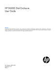
D6000 SERIES QUICK START GUIDE
Version 1.0
Copyright Dutile, Glines and Higgins Corporation, 2011. All Rights Reserved.
Overview
All D6000 series modules contain an EEPROM (Electrically Erasable Programmable Read Only
Memory) to store setup information and calibration constants. The EEPROM replaces the usual
array of calibration potentiometers and DIP switches used to specify baud rate, address, parity,
etc. The memory is nonvolatile which means that the information is retained even if power is
removed. No batteries are used so it is not necessary to open the module case.
The EEPROM provides tremendous system flexibility allowing all of the module’s setup
parameters to be configured remotely through the communications port without having to
physically change a switch or turn potentiometers. There is one minor drawback in using
EEPROM instead of switches; there is no visual indication of the setup information in the module.
To overcome this, each module has an input pin labeled DEFAULT*. By connecting this pin to
Ground, the module is placed in a known communications state called Default Mode.
The Default Mode settings are: 9600 baud, one start bit, eight data bits, one stop bit, and no
parity. The module will only answer to Modbus Slave address “01” in the Default Mode.
Grounding the DEFAULT* pin does not change any of the setups stored in EEPROM. The setup
information may be read to determine all of the setup parameters stored in the module.
Setup information in a module may be changed at any time or while in the Default Mode. The
baud rate and parity setups may be changed without affecting the Default Mode values of 9600
baud and no parity. When the DEFAULT* pin is released, the module automatically performs an
internal reset and configures itself to the baud rate and parity stored in the setup registers.
The Default Mode should only be used with a single module connected to a computer in order to
prevent communications data collisions with other modules on the serial port.
Copyright Dutile, Glines and Higgins Corporation, 2011. All Rights Reserved.
Module Connections
The D6000 series module must be connected to an RS-485 serial port for configuration. See
Figure 1.0 below for an overview of the required connections. Figure 2.0 details connections
between a D6000 and a DGH A1000. Figure 3.0 details connections between a D6000 and a
DGH USB-COMi RS-485 serial converter. Note: No connections are required on the analog or
digital I/O pins to perform the module configuration.
Figure 1.0 General Overview, Default Mode and RS-485 Serial Connection.
Figure 2.0 D6000 to DGH A1000 RS-232 to RS-485 Serial Converter in Default Mode.
Figure 3.0 D6000 to USB-COMi RS-485 Serial Converter in Default Mode.
Copyright Dutile, Glines and Higgins Corporation, 2011. All Rights Reserved.
Software Installation
The first step towards “Getting Started” with your D6000 series module is to connect the module
to an RS-485 serial port using the one of the wiring connection diagrams above. Included within
the wiring connections is the “Default*” line being connected to the power supply ground. This
connection places the module in the “Default Mode”. The Default Mode forces the module into a
known communications state and is best utilized for configuring the module. The serial
communications parameters are: 9600 baud, one start bit, eight data bits, no parity and one stop
bit. The module will only answer to Modbus Slave address “1” (0x01).
Since the modules communicate via the Modbus RTU protocol, a Modbus Master program or the
DGH D6000 series Utility Software will be required to change the module setup register values.
Modbus DGH D6000 Series Utility Software is the best program to use when configuring a
module. The utility software reads the existing module information, displays the information in
easy to understand terms, allows changes to be made via drop-down list boxes and then writes
the new values back to the module.
The D6000 series Utility Software is provided free of charge on CDROM with a purchase order
and the latest version is always downloadable from www.dghcorp.com. The utility software runs
on Windows based computers. Simply insert the CDROM into the CDROM drive, or download the
Setup.Exe file from the website, and then run the SETUP.EXE installation file. The software will
install and create a menu section called “DGH DATA ACQUISITION” and the Utility Software will
be under that selection.
From the computer desktop select the “start” button, select “all programs”, select “DGH Data
Acquisition” and then select “D6000 Series Utility Software” to run the utility software. A desktop
icon is also available to start the program. When the software opens then the first step is to
select, configure and open the serial communications port on the computer that the module is
connected to.
Copyright Dutile, Glines and Higgins Corporation, 2011. All Rights Reserved.
Select “Serial Port” in the upper left corner of the program screen and then select the proper
communications port and press the “Settings” button in the upper right hand corner of the screen.
If the “Default*” line is connected to ground then select 9600 baud, no parity, eight data bits, one
stop bit, RTS Only handshaking and the Tx and Rx delays can be left in their default state.
Otherwise, adjust the settings to match the settings in the module.
Press the “Open Port” or “Update” button to complete the serial port configuration process.
Test Communications
After the utility software serial port has been configured the next step would be to check for valid
communications between the computer and the module. You must have valid communications
with the module before trying to perform the configuration process. To test the communications in
the Default Mode, set the Modbus Slave Address to 0x01. Set the Function selector to 03 and the
Register selection to 40001. Press the “Send” button to verify communications. A typical module
response is shown in the figure below.
Copyright Dutile, Glines and Higgins Corporation, 2011. All Rights Reserved.
The figure above illustrates Modbus function 03 being sent to Slave address 01. Both the
command and response messages are displayed. This command/response format is provided for
troubleshooting purposes. It displays each byte of data being sent to and received from the
module. This information be a good troubleshooting tool or a good way to become familiar with
the Modbus RTU protocol.
The response data value from register 40001 is located in the RSP: line. The data value is a 16bit value located in the fourth and fifth bytes in the message (00 01). The “00 01” indicates that
the register value is 0001. Using the 7CH Current Input Modbus Register map, register 40001 is
the Modbus Slave address. In this example the module slave address value is read back as
0001.
In the event that the module was not detected by the software then the RSP: line would say
“RSP: Timeout – No Response Detected!”. Several things may contribute to this problem. Some
examples are no power to the module, bad RS-485 wiring connection(s), invalid port settings, or
RS-485 half-duplex handshaking problems all can cause timeout errors. Timeout errors must be
corrected before attempting to configure a module.
Copyright Dutile, Glines and Higgins Corporation, 2011. All Rights Reserved.
Setup a Module
After a successful communications test has been performed then the module can be configured.
Select the type of module using the drop-down list box under “Quick Setup” in the lower left hand
corner of the screen. Then press the “Setup” button. A new screen (see below) will appear that
contains list of all the user-selectable module values. The screen below is for a seven channel
current input module.
Ensure that the Module Address in the lower left corner is 01 and then press the “Read Setup”
button. The screen will now populate using the configuration data read from the module.
The user-selectable values are displayed in an easy to understand format and new selections can
be made using the drop-down list boxes. The drop-down list boxes make the configuration
process easy and accurate because erroneous values cannot be entered.
Copyright Dutile, Glines and Higgins Corporation, 2011. All Rights Reserved.
Once the new module configuration settings have been changed to meet the application
requirements then press the “Apply” button to transmit the new settings.
Scan Module Data Values
After the module has been properly configured, the analog input data values can be polled from
the module in order to verify the data from each channel. This feature is a good troubleshooting
or verification tool and should only be used when valid analog input signals are connected to the
module.
The analog input screens contain a “Scan” button that will enable the scanning process. Each
channel is read by requesting the data values from data registers within the module. The analog
input data registers can be found in the Modbus Register map and the data register locations are
specific to the module type.
The data values are returned in unsigned integer hexadecimal percentage of Full Scale format
where a value of 0x0000 represents the minus full scale input of the module. A value of 0xffff
represents the positive full scale input of the module. These values can be viewed to check that
each channel is operating properly when analog signals are applied to the input terminals.
The data values can also be displayed as a numerical value. The utility software knows the plus
and minus full scale input range for each channel. Using the raw hexadecimal percentage of full
scale data values the software can convert these readings to millivolts, milliamps, or temperature
readings. Simply uncheck the “Display Hex Values” selection underneath the channel readings to
display the numeric values.
The scanning process will also log and display the highest (peak) and lowest (valley) readings
that were recorded during the scanning process. This is just for indication purposes only.
A scan interval slide control is also provided to speed up or slow down the scanning process. This
slide control allows the channels to be scanned at intervals from 0.5 to 5 seconds.
Once the setup process is completed then the D6000 is ready to be installed into the application.
Copyright Dutile, Glines and Higgins Corporation, 2011. All Rights Reserved.