1
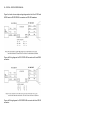
A1000 and A2000 SERIES
CONVERTER BOXES
USERS MANUAL
REVISED:5/1/95
DGH CORPORATION
PO BOX 5638
MANCHESTER, NH 03108
TELEPHONE: 603-622-0452
FAX: 603-622-0487
WEB: www.dghcorp.com
The information in this publication has been carefully checked and is
believed to be accurate; however, no responsibility is assumed for
possible inaccuracies or omissions. Applications information in this
manual is intended as suggestions for possible use of the products and
not as explicit performance in a specific application. Specifications may be
subject to change without notice.
A1000 & A2000 USERS MANUAL 2
GENERAL DESCRIPTION
The A1000 and A2000 series converter boxes convert RS-232
communications signal levels to the correct electrical signals required by
RS-485. The RS-485 communications standard is recommended when
many modules, or other addressable devices, must be connected to a
host computer over long distances. The A1000 and A2000 converters
allow communications bus lengths up to 4,000 meters and baud rates up
to 115K baud using one twisted pair of wires.
The RS-485 communications standard is half-duplex, therefore data can
be transmitted in only one direction at a time. The A1000 and A2000
automatically control the bus direction without external handshaking
signals from the host. Therefore, host software written for RS-232 may be
used without modification. RS-485 bus control is completely transparent
to the user.
The A1000 and A2000 can also operate as RS-485 repeaters. Repeaters
are required to extend communications bus lengths or allow more than
32 RS-485 devices to be connected to a communications bus. A
repeater simply reamplifies, or boosts, existing RS-485 signals
transmitted over long distances.
The A1000 converter boxes are powered by either 115Vac or 230Vac
and contain an internal +24-volt 1A power supply for powering modules.
The A1000 power supply is protected against overloads and short
circuits. The internal power supply may be used to power accessory
circuits such as relays or 4-20mA transmitters. The A2000 converter
boxes operate on a wide range of power supply input voltage:+10 to
+30Vdc unregulated.
3 A1000 & A2000 USERS MANUAL
SPECIFICATIONS
Max Common Mode Voltage: 1500Vrms, 1 minute duration.
NRZ asynchronous data format; 1 start bit, 7 data bits, 1 parity bit and 1
stop bit.
Baud Rates: 300, 600, 1200, 2400, 4800, 9600, 19200, 38400, 57600,
115200.
Temperature Range: Operating and Storage: -25 to +70°C Ambient.
Relative Humidity: 0 - 95% Noncondensing.
A1000 Power Specifications
Power Requirements: 115 or 230 Vac ±10%, 50-60 Hz.
Power Consumption: 30W Full Load.
Power Supply Output: +24Vdc @ 1A.
A2000 Power Specifications
Power Requirements: +10 to +30Vdc unregulated.
Power Consumption (@+15Vdc): Max. Current w/RS-485 output
short,100mA.
Idle Current w/LEDs off, less than 10mA.
MECHANICAL AND DIMENSIONS
Case: Impact resistant ABS.
Weight: 2.8 lbs.(A1000), 1.0 lb.(A2000).
Dimensions:
8.08"W x 2.50"H x 6.25"D (A1000).
7.06"W x 1.53"H x 5.30"D (A2000).
RS-485 Connectors: Phoenix screw terminal barrier plug (supplied).
Replace with Phoenix MSTB 2.5/4 ST 5.08 or equivalent.
Warranty: 12 months on workmanship and materials.
CONNECTIONS
The A1000 and A2000 have three connectors located on the rear panel,
two RS-485 connectors and one RS-232 connector. The RS-485
connectors are 4 position screw-terminal plugs labelled RS-485 IN and
RS-485 OUT. The RS-232 input connector is a female subminiature DB-9
connector labelled RS-232 IN. The functional description of each terminal
is labelled directly above the connector on the rear panel. The RS-485
descriptions are all preceded by letters which correspond to the color
coded wires used in standard telephone cable: (B) Black, (R) Red, (G)
Green and (Y) Yellow. All DGH hardware using RS-485 contains this color
coded nomenclature. Figures 1A & 1B show the rear panel connections
for the A1000 & A2000.
A1000 & A2000 USERS MANUAL 4
A1000/2000 RS-232 DB-9 CONNECTOR
The A1000 and A2000 contain a female DB-9 connector normally used
with modems or other Data Communications Equipment (DCE).This
connector should be connected to a host computer, or controller, when
converting RS-232 signals to RS-485. The Transmit, Receive and
Ground signal lines are all that is required for proper RS-232-to-RS-485
operation. The remaining RS-232 flow control signals Carrier Detect (CD),
Data Set Ready (DSR) and Clear to Send (CTS) are internally biased to
their ACTIVE, or high, using 330 Ohm resistors connected to +10Vdc.
The RS-232 connector pinout is listed below.
Pin #
1
2
3
4
5
6
7
8
9
Description
(CD)
CARRIER DETECT
(TX)
TRANSMIT DATA
(RX)
RECEIVE DATA
(NC)
NO CONNECTION
(GND)
SIGNAL GROUND
(DSR)
DATA SET READY
(NC)
NO CONNECTION
(CTS)
CLEAR TO SEND
(NC)
NO CONNECTION
The RS-232 connector is left open when the A1000 or A2000 is used as
an RS-485 Repeater.
The only connections normally required for proper A1000 operation are
pins 2, 3 and 5 of the DB-9 connector. DB-9 to DB-25 adapters can be
made using the connections below.
DB-9 Pin #
2
3
5
DB-25 Pin #
3
2
7
A1000/2000 RS-485 IN CONNECTOR
The A1000 and A2000 converters contain a four-pin screw-terminal plug
labelled RS-485 IN. This connector is considered the HOST input when
using the A1000 or A2000 as a RS-485 repeater. An RS-485 repeater is
necessary to extend the length of an RS-485 network, or connect more
than 32 RS-485 devices on an RS-485 network.
The RS-485 IN data lines should be attached to the end of an existing
RS-485 network. The serial data received on the RS-485 IN data lines will
be reamplified and retransmitted on to the RS-485 OUT connector data
lines.
5 A1000 & A2000 USERS MANUAL
This connector is left open when the A1000 or A2000 is used as an RS232-to-RS-485 converter.
A1000/2000 RS-485 OUT CONNECTOR
The A1000 and A2000 converters contain a four-pin screw terminal plug
labelled RS-485 OUT. This connector is the RS-485 output for the
A1000 and A2000 when used as either a converter or repeater.
Figure 1A Connections for A1000.
Figure 1B Connections for A2000.
A1000 & A2000 USERS MANUAL 6
BAUD RATE
The A1000 and A2000 series converters each contain a 10-position DIP
switch located on the rear panel. The DIP switch is used to select the
correct communications baud rate and must be set to the same value as
the devices connected to the RS-485 OUT connector. Only one baud
rate switch may be turned on at one time.
LEDS
The A1000 contains three status LEDs labelled FAULT, POWER and
TRANSMIT located on the converter front panel. The A2000 contains
two status LEDs labelled PWR and TX located on the converter rear
panel. The status indicators are useful while troubleshooting suspected
system faults and provide visual status indication during normal system
operation.
The A2000 converter LEDs may be disabled internally. Low power
applications, typically powered by batteries or solar panels, can benefit
significantly by disabling the status LEDs. The A2000 power
consumption may be reduced by up to 50% with the LEDs disabled. To
disable the status LEDs, remove the A2000 top cover and locate the 3pin strip on the PC board directly behind the LEDs. Lift the jumper bar
from the pin strip and place it over the two pins located closest to 'LEDS
OFF' written on the PC board.
The POWER (A1000) and PWR (A2000) LEDs are pilot lights that
indicate adequate power supply voltage is applied to the converter.
The TRANSMIT (A1000) and TX (A2000) LEDs illuminate as data is
transmitted from a host computer onto the RS-485 communications bus.
The illumination intensity will vary and may become hard to detect as the
baud rate increases.
The A1000 FAULT LED will illuminate if excessive current is being drawn
from the internal +24Vdc one amp power supply.
RS-485 TERMINATIONS
The proper termination techniques for any RS-485 system require two
biasing resistors and two termination resistors. There must be one pull-up
resistor between the DATA+ line and +5Vdc on each RS-485 network.
There should also be a pull-down resistor from the DATA- line to ground.
These two resistors are the biasing resistors and are normally positioned
at the HOST end of the cable. The RS-485 standard also requires two
resistors across the data lines for proper termination. Two 220 Ω resistors
should be placed across the data lines DATA+ and DATA-. The resistors
7 A1000 & A2000 USERS MANUAL
should be placed at each end of the RS-485 cable. Please refer to Figure
2 for a typical RS-485 system application.
The A1000 and A2000 each contain the biasing and termination resistors
necessary to interface any equipment on an RS-485 network. These
resistors are switch-selectable making it easier to interface the A1000 and
A2000 to other pieces of equipment that may or may not contain the
biasing and/or termination resistors.
Figure 2. RS-485 biasing & termination resistors.
A1000 RS-485 TERMINATIONS
Each A1000 contains internal RS-485 termination and biasing resistors
for proper termination of a RS-485 system. The resistors are enabled or
disabled via two 3-position DIP switches located on the A1000 rear panel.
One three-position switch enables termination resistors for the RS-485 IN
(HOST) data lines and the other switch enables termination of the RS485 OUT data lines. The three-positioned DIP switches are located to the
left of each RS-485 connector on the A1000 backpanel. The three
positioned switches are used to enable or disable a 1KΩ pull-up between
+5Vdc and the DATA+ line, a 1KΩ pull-down resistor between the DATAline and ground or a 220 Ω termination resistor between the DATA+ and
DATA- lines. Each switch is labelled +1K, -1K and 220. Set the
appropriate switch to the "up" position to enable a resistor.
NOTE: The RS-485 IN +1K and -1K switches should be "up" when the
A1000 is used as a RS-232/RS-485 converter.
A1000 & A2000 USERS MANUAL 8
A2000 RS-485 TERMINATIONS
Proper biasing and termination resistors in the A2000 may be enabled by
using the internal jumpers contained in the A2000. Figure 3 shows the
location of the jumpers on the A2000 printed circuit board. The jumpers
are shown in the factory setting to enable a resistor, insert a jumper into
the jack position adjacent to the resistor nomenclature written on the
A2000 printed circuit board.
NOTE: The RS-485 IN +1K and -1K jumpers should be installed when
the A2000 is used as a RS-232/RS-485 converter.
FACTORY RS-485 TERMINATION SETTINGS
A1000: 300 BAUD, +1K, -1K on RS-485 IN & RS-485 OUT connectors
enabled, all other switches off.
A2000: 300 BAUD, +1K, -1K, on RS-485 IN & RS-485 OUT enabled via
internal jumpers, all other termination jumpers disabled.
Figure 3. A2000 jumper locations.
9 A1000 & A2000 USERS MANUAL
Figue 4a,b and c show simple wiring diagrams for both the A1000 and
A2000 used as RS-232/RS-85 converters and RS-485 repeaters.
Figure 4a Wiring diagram for RS-232/RS-485 converter with host DB-9
connector.
Figure 4a Wiring diagram for RS-232/RS-485 converter with host DB-25
connector.
A1000 & A2000 USERS MANUAL 1 0
Figure 4c Wiring diagram for RS-232/RS-485 converter and RS-485
repeater .