1
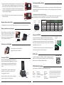
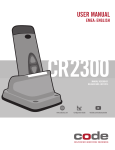
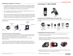
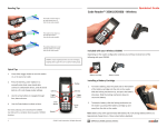
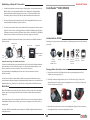
Quickstart Guide
Establishing a Bluetooth® Connection
1. If establishing a Bluetooth connection using the Charging Station with embedded CodeXML®
Modem, slide the Communication Mode Switch on the bottom of the Charger/Modem
Station to Bluetooth mode (the direction of the arrow). For USB communication mode
information, please reference the CR2300 User Manual located at www.codecorp.com.
2.
Code Reader™ 2300 (CR2300)
Scan the QuickConnect Code located on the front of the Charger/Modem Station or on the
external CodeXML® M3 Modem. (Figures 13 and 14).
3. The wireless icon located at the top of the reader will flash as it attempts to make connection.
(Figure 15) The blue LED on the Charging Station (or CodeXML® M3 Modem) will also flash as
it attempts to connect and will turn solid when the connection is established. The CR2300 will
beep once and the wireless icon will flash every 10 seconds. (Figures 13, 14 and 15)
For additional CodeXML® M3 Modem information, please reference the CodeXML® M3 Modem
QuickStart Guide.
QuickConnect
Code
Blue
LED
Figure 13
Figure 14
Wireless Icon
Blue
LED
Storage Icon
CR2321
Included with the CR2300
Depending on the kit purchased, a combination of the following components will be included with
your reader:
Good Read
Indicator
Figure 15
Important Note If Using a non-Code Bluetooth Device:
To connect to a Bluetooth device not manufactured by Code, you will need the Bluetooth address
(often referred to as the BD_ADDR) of that device. The 12-character Bluetooth address can be
found on the device near the serial number. Then visit Code’s web site at:
http://www.codecorp.com/bdaddr.php and enter the 12-character address to create the
QuickConnect Code.
You will need to locate the Communications (COM) Port assigned to the Bluetooth serial port
protocol before installing the Bluetooth Configuration Manager software that is included with your
Bluetooth adapter (e.g., COM 10). This is the COM Port through which the CR2300 will connect.
Batch Mode
Charging Station with
or without
an Embedded
CodeXML® Modem
Battery
Cartridge
USB
Cable
Power
Supply
CodeXML®
M3 Modem
with RS232 or
USB Cable
Screws and
Rubber Feet
Weighted
Base Plate
Charging Station Assembly Instructions
1. Plug the barrel side of the USB charge cable or power supply (depending on which you
ordered) into the charger. (Figure 1)
2. (Optional) To attach the weighted base, place the ‘This Side Down’ (Figure 2) side of the
weighted base onto the surface, place the Charging Station on top of it (Figure 3) and secure
with the screws provided. (Figure 3)
When the CR2300 is in batch mode, the storage icon (Figure 15) will remain solid to indicate data
has been stored. The storage icon will flash every 10 seconds to indicate data is stored when in
sleep mode.
If the storage memory is full, the storage icon will flash 5 times every second. Data will need to be
downloaded or deleted to free up memory space. Note, the storage icon will not flash if there is
no data stored.
To put the CR2300 into Batch Mode, please reference the CR2300 Configuration Guide located at
www.codecorp.com.
© 2013 Code Corporation. All rights reserved.
Figure 1
Figure 2
Figure 3
3. Rubber feet can be placed on the corners of the weighted base (Figure 4) or directly onto the
Charging Station (Figure 5) to prevent slipping from a surface.
C008663_01_CR2300_QuickStart_Guide
4. (Optional) To mount the Charging Station to a surface place the ‘This Side
Down’ (Figure 4) side of the weighted base onto the surface and secure
with screws. Note: Because surface types differ, screws are not included
to mount a Charging Station to a surface. Place the Charging Station on
top of the secured weighted base (Figure 3) and secure to the base with
the screws provided (Figure 3)
Fuel Gauge Battery Status
Check Battery Life
Press the fuel gauge button (Figure 10) to determine remaining battery life. If the battery has less
then 10% capacity, the first LED will flash rapidly. For 25% or greater capacity, the LEDs will flash
ON for 4 seconds.
Figure 4
Fuel Gauge Status Indicator While Charging
If the battery has less then 10% capacity, the first LED will flash rapidly while charging. For 25% or
greater capacity, the LEDs will flash ON for 4 seconds and OFF for 1 second. (Figure 11)
5. Plug the USB cable into the computer’s USB port or the power adapter
into the wall outlet.
Figure 5
Fuel Gauge
Button
Weighted Base Adapter Plate
Fuel Gauge
Indicators
The weighted base has the same pre-drilled mounting holes as the ECS-H and UMC Chargers.
Battery Installation and Removal
Figure 10
Place the battery into the reader as shown in
Figure 6. Once in place, the battery will snap
and lock to indicate proper installation. For
battery removal, slide the latch (Figure 7), to
unlock and release the battery.
Latch
<10%
Rapid Flashing
<25%
ON
25-50%
ON
ON
50-75%
ON
ON
ON
75%+
ON
ON
ON
Powering on the Reader
Using the CR2300
The CR2300 will beep and the good read indicator will flash green to
indicate a ‘good read’ has occurred. (Figure 12)
Press and hold either of the buttons or
trigger for one second, to power on.
ON
Figure 11
Press and hold a button or trigger on the CR2300, the two blue bars
emitting from the reader are used for targeting. Center the blue bars in
the middle of a bar code. When the bar code is in the reader’s field of
view and at the optimal distance (4” from the bar code) , the reader will
automatically read the code.
Figure 7
Figure 6
Battery Life
Good Read
Indicator
Figure 12
Suffix Enter
Figure 8
The default setting on the CR2300 has Suffix Enter disabled. To enable
Suffix Enter, scan the following configuration code. For RS232 Settings,
please refer to the CR2300 Configuration Guide.
Charging a CR2300
Batteries ship with approximately 50% battery life
and should be completely charged before initial use.
Approximate time to charge a depleted battery is 4
hours via USB cable and 2 1/2 hours via AC power
supply.
CR2300 Default Settings
Out of the box the CR2300 will read the following bar codes:
To charge a reader, remove the plastic ‘Remove
Before Use’ cap, and place the reader into the
Charging Station. (Figure 9)
When the reader is seated correctly, the Charging
Indicator LED (Figure 9) will turn green.
www.codecorp.com
Suffix Enter - USB
Charge
Indicator
Figure 9
Aztec
Codabar
Code 39
Code 93
Code 128
Data Matrix
Data Matrix Rectangle
GS1 DataBar
Int 2 of 5
MSI Plessey
PDF417
QR Code
UPC/EAN/JAN
To configure a CR2300 to read bar codes not
listed, download the CR2300 Configuration
Guide from www.codecorp.com and scan
the appropriate ‘Enable’ bar code reading
symbology configuration code.
www.codecorp.com