1
5.8 Configuration /
Hard-copy for correction
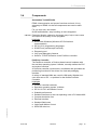
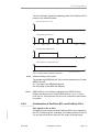
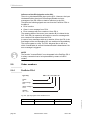
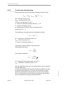
The error indicator signals the operating state of the PacDrive PS-4
based on the following states:
LED permanent off: no error
n
f
t in sec
LED fast flash: general error
n
f
0
0.26
0.51
1.02
2.05
t in sec
1.02
2.05
t in sec
LED slow flash: SERCOS error
n
f
0
LED permanent on: fatal system error
n
f
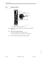
Diagnose LED PS4 us fh8
t in sec
Fig. 5-7: Display state of diagnosis LED "err"
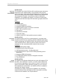
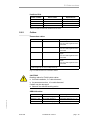
S1/S2
address setting rotary switch
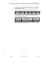
The double-digit SERCOS (00 - 99) must be unabmiguous for each
SERCOS slave.
S1: Tens digit of the SERCOS address
S2: Ones digit of the SERCOS address
buserr
SERCOS bus error indicator (signalled from SERCOS bus)
Display that shows errors of the SERCOS bus. It is on, if a bus
error occurs. This state can also occur for a short time and cannot
be quitted.
5.8.2
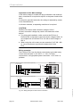
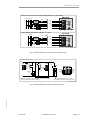
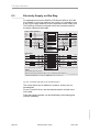
Combination of PacDrive SCL and PacDrive PS-4
SCL signals in the m PS-4
PD_OpManPS-4_05_us.fm
All Ready signals of the individual PacDrive SCLs come together in
the PS-4, where they are evaluated. The Ready contact on the PS4 is not set until all SCLs and the PS-4 supply a Ready signal.
ELAU AG
PacDrive PS-4 / PD-8
page 37