1
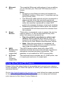
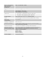
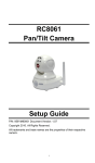
RC8061 Pan and Tilt Camera Installation Guide P/N: 956YM801GJ Document Version: 1.07 Copyright 2011 All Rights Reserved. All trademarks and trade names are the properties of their respective owners. i Package Contents The following items should be included: If any of these items are damaged or missing, please contact your service provider immediately. 1. Pan and Tilt Camera 2. 6 feet long Power adapter 3. Mounting Bracket 4. Three (3) Mounting Screws 5. Three (3) Mounting Anchors 6. Ethernet Cable ii 1 Chapter 1 Introduction This Chapter provides details of the Pan and Tilt Camera's features, components and capabilities. Overview The Pan and Tilt Camera has an Integrated Microcomputer and a high quality Image Sensor, enabling it to display high quality live streaming video. Using enhanced MPEG4 technologies, the Pan and Tilt Camera is able to stream high quality video and audio. The high compression capabilities of MPEG4 reduce network bandwidth requirements to amazingly low levels. With built-in Passive Infrared sensor and White Light LEDs, the Pan and Tilt Camera can provide home security and illumination up to approximately 16 feet under low light conditions in a simple, economical manner. Features Standalone Design: The Pan and Tilt Camera is a standalone system with built-in CPU and Video encoder. It requires only a power source and a connection to your Router. Dual Video Support: The Pan and Tilt Camera can support both MPEG4 and MJPEG video for different image compression. Wired and Wireless Network Support: The Pan and Tilt Camera supports either wired or wireless transmission. PIR (Passive Infrared Sensor) Enhanced Motion Detection: The Pan and Tilt Camera is embedded with a PIR Sensor, which senses infrared light radiating from moving objects within its field of view. Motion detection for large objects, which are undetectable by the PIR Sensor, is achieved by built-in software that compares consecutive video frames for changes. When motion is detected, an alert can be sent, or some other action may be triggered. . White Light LEDs Support: The Pan and Tilt Camera has 4 white light LEDs. The LEDs can provide illumination up to approximately 16 feet that can help to output a better video quality while under lowlight conditions such as indoors, on cloudy days, or in the morning or evening. The white light can be used to deliver warning as well. 1 Wireless Features Standards Compliant: The Pan and Tilt Camera complies with the IEEE802.11g (DSSS) specifications for Wireless LANs. Supports both 802.11b and 802.11g Standards: The Pan and Tilt Camera supports both 802.11b and 802.11g standards. Speeds up to 54Mbps: All speeds up to the 802.11g maximum of 54Mbps are supported. Security Support: Full WEP (64/128 Bit), WPA and WPA2 Personal standards are supported on the Wireless interface, allowing advanced encryption of wireless data. 2 2 Chapter 2 Basic Setup This Chapter provides details on how to install and configure the Pan and Tilt Camera. You can also refer to details about assembly of this device in the online setup wizard at http://monitoringcontrol.verizon.com System Requirements To use the Wired Interface, a standard router and network cable are required. To use the Wireless interface on the wireless model, other Wireless devices must be compliant with the IEEE802.11b or IEEE802.11g specifications. All Wireless stations must use compatible settings. Physical Details - Pan and Tilt Camera Front Panel - Pan and Tilt Camera Figure 1: Front Panel – Pan and Tilt Camera 3 1. Lens No physical adjustment is required or possible for the lens, but you should ensure that the lens cover remains clean. The image quality is degraded if the lens cover is dirty or smudged. 2. Microphone The Pan and Tilt Camera comes with a built-in (Not microphone. currently supported) 3. Power LED On - Powered on Off - No power Blinking - The Power LED blinks during start up. This can take up to 20 seconds 4. Passive Infrared (PIR) Sensor The PIR sensor is designed for human body detection. 5. Privacy Button When the privacy feature is enabled, live video cannot be accessed. On (Green) - The privacy feature is activated Off - The privacy feature is not in use 6. Network LED The Network LED displays the current status of the Pan and Tilt Camera’s connection to the Network via either the Wired or Wireless interface. On (Green) – Pan and Tilt camera is connected to Network Off - Pan and Tilt Camera is not connected to the Network Blinking (Green) - Data is being transmitted On (Amber) - If the LED is on for 5 seconds, the WPS is not processing successfully Blinking (Amber) - WPS function is being processed successfully 7. Active LED Off - No user is viewing the camera Blinking - User(s) is viewing the camera 8. White Light LEDs The White Light LEDs are designed for the supply of backlight under low-light environment. 9. Echo Eliminator Echo Eliminator can reduce background noise to provide better voice quality. 4 Rear Panel - Pan and Tilt Camera Figure 2: Rear Panel – Pan and Tilt Camera 1. Antenna The antenna is adjustable; best results are usually obtained with the antenna positioned vertically. 2. Speaker Out (Not currently supported) An external speaker can be plugged in here. 3. Power Port The supplied 5V power adapter plugs in here to power on the Pan and Tilt Camera. Note: Do not use any other power adapters since doing so may damage the Camera. 5 4. Ethernet Port The supplied Ethernet cable plugs in here enabling you to connect your Pan and Tilt Camera to your router. Note: Plugging in the Ethernet cable will disable the Wireless interface. Only one (1) interface can be active at any time. The Ethernet cable should only be connected or disconnected when the camera is powered OFF. Attaching or detaching the Ethernet cable while the camera is powered on does NOT switch the interface between wired and wireless. Detaching the Ethernet cable when the camera is powered ON will disconnect the camera from the network. 5. Reset Button This button is recessed; a pin or paper clip can be used to press it. It can be activated at any time when the camera is powered up. Reset to default manufacturer values and reboot. When pressed and held for over 10 seconds, the settings of Pan and Tilt Camera will be set to their default manufacturer values. Note: After this procedure is completed, all LEDs will blink three times to confirm that the reset was successfully completed. 6. WPS Button (Not currently supported) The WPS feature when used with other WPS enabled wireless devices automatically creates an encryption-secured wireless connection. The gateway is not enabled for WPS connectivity. 7. IO Ports (Not currently supported) The terminal block includes two (2) GND ports, one (1) input port and one (1) output port. Setup the Pan and Tilt Camera Please follow the steps below to assemble and connect your camera. Once complete, you have the option to utilize your camera in a wired or wireless fashion. Go to http://monitoringcontrol.verizon.com and follow the steps provided in the online Setup Wizard. This will enable you to setup and connect your camera to the Home Control Network. 6 You may also follow the steps below to assemble your camera and then visit the online Setup Wizard to connect your camera. Step 1: Check the Antenna a. Ensure the antenna is attached to the Pan and Tilt Camera. b. Put the antenna in the upright position to improve wireless reception Step 2: Visit the Online Portal a. Visit http://monitoringcontrol.verizon.com and follow the simple steps provided in the online Setup Wizard. This will enable you to setup and connect your camera to the Home Control network * Optional: Mount the Pan and Tilt Camera *Note: The Pan and Tilt Camera can also be placed on a table using the stand provided. Note: Please ensure the Pan and Tilt camera is configured and added to the network before permanent mounting. Step 1: Install Mounting Bracket a. Drill three holes in the ceiling, in the formation shown below, where you would like to install the Pan and Tilt Camera. 7 b. Push the mounting anchors into the drilled holes c. Screw the three mounting screws through the mounting bracket into the mounting anchors. Step 2: Mount the Camera Slide the Pan and Tilt Camera into the bracket and secure it firmly. 8 A Appendix A Specifications Pan and Tilt Camera Model Pan and Tilt Camera Dimensions 90mm (W) * 35mm (H) * 90mm (D) Built-in Speaker 8 ohm, 0.5W (Not Currently Supported) 9 Built-in Microphone 6mm, -40 dB+3db, >55dB (Not Currently Supported) Light Sensor Min low lux trigger value: 0.5 lux PIR Sensor Sensitivity distance: 5 meters Angle degree: 100°(cone) Focus distance: 6~9 meters Pan & Tilt Pan (320° / 4 seconds): left 160°, right 160° Tilt (120° / 0.8 second); up 90°, down 30° Image Sensor Omni Vision OV7725 1/3.75” CMOS Sensor Lens F4.57mm @F2.0 Fixed Focus lens (board lens, 2P2G) Operating Temperature 0 C to 40 C Storage Temperature -20 C to 70 C Network Protocols TCP/IP, DHCP, SMTP, NTP, HTTP, FTP, RTP, RTSP, UPnP (Discovery/Traversal) Network Interface 1 Ethernet 10/100BaseT (RJ45) LAN connection Wireless interface (Wireless Model Only) IEEE 802.11b/802.11g compatible, Infrastructure/Ad-hoc mode, WEP/WPA Personal/WPA2 Personal security support, roaming support LEDs Ready (green) Active (green) Network (green) Power Adapter 5V/2A DC External 10 Regulatory Approvals CE Approvals The Pan and Tilt Camera and the Ethernet Pan and Tilt Camera meet the guidelines of the European Union and comply with the 99/5/EEC and RTTE 99/5EG directives, including the following standards: EN60950 EN300 328-2 EN301 489-1 EN301 489-17 This is a Class B product. In a domestic environment this product may cause radio interference in which case the user may be required to take adequate measures. 11