1
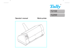
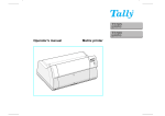
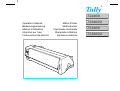
T2240/9
Operator’s Manual
Bedienungsanleitung
Manuel d’utilisation
Istruzioni per l’uso
Instrucciones de servicio
Matrix Printer
Matrixdrucker
Imprimante matricielle
Stampante a Matrice
Impresora matricial
T2240/24
T2340/9
T2340/24
Important Information
This equipment generates and uses radio frequency energy and if not
installed and used properly, that is, in accordance with the manufacturer’s
instructions, may cause interference in radio and television reception. It
has been type tested and found to comply with the limits for class B
computing devices in accordance with the specification in subpart J of part
15 of FCC rules, which are designed to provide reasonable protection
against such interference in a residential installation. However, there is no
guarantee that interference will not occur in a partial installation. If this
equipment does cause interference to radio or television reception, which
can be determined by turning the equipment off and on, the user is
encouraged to try to correct the interference by one or more of the following
measures:
Reorient the receiving antenna,
Relocate the peripheral away from the receiver,
Move the peripheral away from the receiver
Plug the peripheral into a different outlet, so that the peripheral and
receiver are on different branch circuits
If necessary, the user should consult the dealer or an experienced
radio/television technician for additional suggestions. The user may find
the following booklet, prepared by the Federal Communications Commission, helpful: “How to Identify and Resolve Radio-TV Interference
Problems”.
This booklet is available from the U.S. Government Printing Office, Washington DC 20402 Stock No. 004.000.00345.4.
WARNING: To comply with FCC regulations on electromagnetic interference for a class B computing device, the printer cable must be shielded.
To assure compliance with FCC regulations for a computing device, use
a shielded interface cable with a metal shell connector. The use of cables
not properly shielded may result in violating FCC regulations.
This digital apparatus does not exceed the class B limits for radio noise
emissions from digital apparatus as set out in the radio interference
regulations of the Canadian department of communications.
This unit complies with DOC standard C108.8-M 1983
ATTENTION: Le présent appareil numérique n’ement pas de bruits
radioélectriques déspassant les limites applicables aux appareils
numériques de la classe B prescrites dans le règlement sur le brouillage
radio- électrique édicté par le minstère des communications du Canada.
The paper used is made of raw materials treated with a chlorine-free
bleaching process.
Das verwendete Papier ist aus chlorfrei gebleichten Rohstoffen
hergestellt.
Le papier utilisé est fabriqué à partir de matières premières blanchis sans
chlore.
This device fulfils the European standards requirements by complying with the Directive of the Commission
dated May 3, 1989 (89/336/EEC) relating to electromagnetic compatibility and the Directive dated February 19,
1973 (73/23/EEC) relating to low-voltage electrical equipment. Conformity with the above mentioned Directives
is indicated by the CE symbol attached to the device.
Note: Conformity may be affected by:
using interface cables not complying with the specifications
non-observance of important instructions in the operator’s manual
installing components not approved for this device by the manufacturer
unauthorized manipulation
Dieses Gerät erfüllt die Anforderungen der Europäischen Normen durch Einhaltung der Richtlinie des Rates
vom 3. Mai 1989 (89/336/EWG) bezüglich der Elektromagnetischen Verträglichkeit sowie die Richtlinie vom 19.
Februar 1973 (73/23/EWG) bezüglich Elektrischer Betriebsmittel mit Niederspannungen. Die Konformität zu
den oben angeführten Richtlinien ist durch das am Gerät angebrachte CE-Zeichen gekennzeichnet.
Hinweis: Die Konformität kann beeinflußt werden durch:
Benutzung von nicht spezifizierten Schnittstellenkabeln
Nichtbeachtung wichtiger Hinweise der Bedienungsanleitung
Ersetzen von Bauteilen, die nicht vom Hersteller für dieses Gerät freigegeben wurden
Eingriffe durch Unbefugte
Cet appareil remplit aux exigences des normes européennes en respectant la directive du Conseil du 3 mai
1989 (89/336/CE) relative à la compatibilité électromagnétique et la directive du 19février 1973 (73/23/CE) en
matière du matériel à basse tension. La conformité aux directives mentionnées ci-dessus est repérée par la
marque de conformité de la Communauté Européenne (CE).
Remarque: La conformité peut être influencée par:
l’utilisation de câbles d’interface non spécifiés
le non-respect de consignes importantes du manuel d’utilisation
le remplacement de composants qui n’ont pas été homologués pour cet appareil par le constructeur
l’intervention de personnes non autorisées
Questo apparecchio soddisfa le richieste delle norme europee rispettando la direttiva del consiglio del 3 Maggio
1989 (89/336/CEE) relativa alla compatibilità elettromagnetica nonché la direttiva del 19 Febbraio 1973
(73/23/CEE) relativa a mezzi di produzione elettrici a bassa tensione. La conformità alle direttive sopra citate
è contrassegnata con il simbolo CE applicato sull’apparecchio.
Nota: La conformità può essere influenzata tramite:
Utilizzo di cavi interfaccia non specificati
Inosservanza di importanti indicazioni delle istruzioni per l’uso
Sostituzione di componenti per i quali non è stato dato il benestare dal produttore per questo apparecchio
Interventi tramite persone non autorizzate
Este equipo corresponde a lo exigido en las normas europeas a base del cumplimiento de la directriz del Consejo
del 3 de mayo de 1989 (89/336/CEE) en lo que se refiere a la compatibilidad electromagnética así como de la
directriz del 19 de febrero de 1973 (73/23/CEE) en lo que se refiere a los materiales eléctricos con bajas
tensiones. Para señalizar la conformidad con las directrices antes mencionadas, el equipo está dotado de la marca CE.
Indicación: La conformidad puede estar influida por:
la utilización de cables de interface no especificados
La carta utilizzata è prodotta con materiali sbiancati senza cloro.
la inobservancia de indicaciones importantes contenidas en el manual de servicio
El papel utilizado ha sido fabricado con un proceso de blanqueo libre de
cloro.
la sustitución por componentes, que no han sido homologados por el fabricante para el equipo en cuestión
intervenciones de personas no autorizadas
WARNING
Only trained and qualified personnel may open covers or remove parts that are not explicitly shown and described in the User Guide as being accessible to
the operator.
WARNUNG
Das Entfernen oder Öffnen von Abdeckungen und Teilen darf nur durch geschultes Fachpersonal vorgenommen werden. Ausgenommen hiervon sind nur
solche Abdeckungen und Teile, deren Entfernen bzw. Öffnen in der Bedienungsanleitung ausdrücklich gekennzeichnet und beschrieben sind.
ATTENTION
Seul un personnel qualifié et formé est habilité à démonter les sous-ensembles de la machine qui ne sont pas formellement indiqués dans le Manuel
d’utilisation meme s’ils sont accessibles par l’opérateur.
ATTENZIONE Solo personale qualificato puo’accedere a parti che non siano esplicitamente descritte nelle Istruzioni per l’operatore come accessibill all’operatore.
ADVERTENCIA Las cubiertas y piezas sólo deberán ser quitadas o abiertas por personal especializado. Se exceptúan de esta regla sólo las cubiertas y piezas cuya
retirada y apertura estén indicadas y descritas expresamente en las Instrucciones de uso.
Quick start-up
Operator’s Manual
QUICK START-UP
Introduction
Symbols used in this manual
Important safety instructions
Using the online documentation
Troubleshooting
The printer at a glance
Installation
Unpacking the printer
Positioning your printer
Connecting the printer
Switching the printer on and off
Control panel
Online mode
Offline mode
Setup mode
Installing the ribbon cassette
Loading paper
Cut Sheet paper
Printer in fanfold paper mode
Changing the paper type
Paper path quick selection
Paper transport
Using
Moving paper to the tear position
Settings (I)
Setting the tear position
Setting the first printing line (TOF)
Settings (II)
Setting the print head gap
Changing paper in Setup mode
From fanfold paper to single sheet mode
From single sheet to fanfold paper mode
Selecting a font
Setting the character pitch
Specifications
Printer specifications
Paper specifications
Accessories
2
2
2
2
2
3
5
5
5
6
6
7
7
7
7
8
10
10
12
14
14
15
15
15
16
16
16
18
18
19
19
20
21
22
23
23
23
24
1
ENGLISH
Table of contents
Introduction
Quick start-up
Introduction
Ah ha!
➤ Symbols used in this
manual
STOP
This Operator’s Manual is intended as a quick introduction into working with the printer and is
to enable also unexperienced users to handle the device properly. It describes the most important
functions of the printer and contains the essential information for your everyday work with the
printer. A more detailed description of the printer, its characteristic features and further information is contained in the reference manual on the online CD-ROM which is included at the back
of this manual.
Important information is highlighted in this manual by two symbols.
CAUTION marks information which must be observed in order to prevent injuries to the user
and damage to the printer.
NOTE marks general or additional information about a specific topic
➤ Important safety
instructions
Read the following instructions carefully before putting the printer into operation in order to
protect yourself from injury and avoid damage to the printer.
Keep this Operator’s Manual always readily accessible.
Place the printer on a stable surface so that it cannot fall down to the ground.
Avoid exposing the printer to high temperature or direct sunlight.
Keep all liquids away from the printer.
Do not expose the printer to shock, impact or vibration.
Never switch on the printer when it is not set to the correct voltage.
STOP
Never try to carry out maintenance and repair work yourself; always call a qualified service
technician.
STOP
When you want to disconnect the printer from the mains power supply, always pull out the
mains plug from the wall outlet.
You will find additional safety information at specific places in the text.
➤ Using the online
documentation
➤ Troubleshooting
2
First install the Adobe Acrobat Reader on your hard disk unless the program has already been
installed. To install it, follow the steps described in the README file in the READER directory.
To start the online documentation, call the File Manager (Windows 3.1) or Explorer (Windows 95/Windows 98/Windows NT) and double click on the START.PDF file. Then follow the
instructions and menus on the screen.
If your CD-ROM should be defective or missing, please consult your dealer.
The online documentation is also available as a printed manual (for a small fee) and via the
internet.
Minimum hardware requirements: PC AT 486, 4 x CD-ROM, 15" monitor, mouse.
The online documentation supplied on the CD-ROM contains detailed information on troubleshooting.
Quick start-up
The printer at a glance
The following figures show the name of each printer part, and the table on the following page
shows the functions of each part.
Paper Extension Trays
ENGLISH
The printer at a
glance
Paper Tray
Access Cover
Operation Panel
Left Paper Guide
Paper Feed Knob
Power Switch
Cut Sheet Paper Insert Guide
Option Connectors
Right Paper Guide
Front Cover
Perforated Line Cutter
Paper Type Selection Lever
Paper Thickness Adjustment Lever
Latch Lever
Rear Covere
Power Inlet
Interface Connector
Latch Lever
3
The printer at a glance
4
Quick start-up
Name
Functions
Operation Panel
It indicates the printer status, and is used to change various settings.
Paper Tray
It is used as a paper support for cut sheet paper already printed when the
option “F-Eject” is set to OFF in the Initial Setting.
Paper Extension Trays
They are used for extending of the Paper Tray.
Access Cover
When the Ink-ribbon Cartridge is to be replaced or paper jams are to be
removed, this cover is detached to allow access to the related parts. It also
serves to protect operators from the mechanical movements of the printer.
Paper Feed Knob
It is used to manually feed paper forward or backward.
Power Switch
It is used to turn ON or OFF the power of the printer.
Option Connector
It is used to connect an Auto Sheet Feeder (ASF) or the Optional 2nd
Tractor.
Paper Type Selection
Lever
It is used to select the appropriate type of paper to be used in the printer:
Cut Sheet Paper (upper position)
Continuous Form Feed Paper (lower position)
Front Cover
It is opened when Continuous Form Feed Paper is to be set. This cover is
detached when an Auto Sheet Feeder (ASF) or the Optional 2nd Tractor is
to be attached.
Right Paper Guide
By aligning the right edge of the Cut Sheet Paper to this guide, an uneven
feed can be prevented.
Cut Sheet Paper Insert
Guide
It is opened for inserting Cut Sheet Paper and is used as a paper support.
It is also used as a support for post-print Cut Sheet Paper when the option
“F-Eject” is set to ASF, Single or ALL in the Initial Setting.
Left Paper Guide
It is used to adjust the left margin of the Cut Sheet Paper.
Latch Lever
By pulling this lever to the front, the latch is released and the Access
Cover can be opened.
Perforated Line Cutter
Continuous Form Feed Paper will be cut at this position. By pressing the
Tear key after printing, paper feeds up to this position.
Paper Thickness Adjustment Lever
It is used to adjust the paper-pinching strength of the printer in accordance
with the thickness of the paper to be used. As for the adjustment ranges,
see Paper Thickness Adjustment, page 18.
Interface Connector
It is used to connect the I/O cable to the system unit.
Power Inlet
It connects to the power cord.
Rear Cover
It is used to reduce noise. It must be removed when the paper tray is in
upright position.
Quick start-up
Installation
➤ Unpacking the printer
Please open the printer package and check that all the following items are included.
Unpacking Instructions
Operator’s Manual
Printer
If any item is missing or damaged, please contact the store where
the product was purchased.
Remove the transport protection elements as described in the
unpacking instructions.
The carton and the packing materials will be necessary for
moving or transporting the printer. Please store them in a safe
place.
CD-ROM
Ink-ribbon
➤ Positioning your
printer
Power Cord
Place the printer on a stable, flat and non-slip surface in such a way that it cannot fall down.
Ensure easy access to the control panel and the paper feeders and leave sufficient space for the
paper ejected.
If frequent forward and return feed movements will be performed with fanfold paper, you should position the printer as
illustrated in the figure.
When choosing a suitable place for your printer, you should also
observe the following:
STOP
Never place the printer near sources of easily inflammable gas or explosive substances.
■ Avoid exposing the printer to direct sunlight. If you cannot
avoid placing the unit near a window, protect it from sunlight
with a curtain.
■ Position the printer near the computer to which it will be
connected. The distance must not exceed 2 m.
■ Ensure sufficient distance from radiators.
■ Ensure that the printer is not exposed to extreme variations
in temperature or air humidity. Avoid exposure to dust.
5
ENGLISH
Installation
Installation
Quick start-up
➤ Connecting the printer
Make sure that the unit is set to the correct voltage (i.e. 230 V
for Europe, 120 V for the USA). Refer to the type plate beside
the power inlet on the rear side of the printer.
If this is not the case, contact your dealer.
Type Plate
STOP
Never switch on the printer when it is not set to the
correct voltage since this could cause severe damage.
Connect the power cable to the printer’s power
inlet as shown in the figure.
Connect the power cable plug to a wall outlet.
STOP
Make sure that the printer and the computer are
switched off.
Connect the printer-end connector of the data
cable to the female interface connector and secure it with the
spring clips.
Connect the other end of the cable to the computer.
➤ Switching the printer on and off
The power switch, which is used for switching the printer on
and off, is located at the right side of the printer.
Power Switch
6
Quick start-up
Control panel
Control panel
The first line of the display informs you about whether the printer is in Online or in Offline
mode and about the paper path selected (Trac.1 or Single).
➤ Online mode
Online
When switching on the printer, it automatically selects Online mode. It can receive data from the
computer only in this mode.
Trac.1
Tear
Online
➀ Sets the printer to Offline mode.
➀ ➁
Setup
Sets the printer to Setup mode.
➂ Tear key: Activates the tear function when fanfold paper is loaded
(see page 15). If Load is displayed above this key, no paper is loaded in
the printer; press the key to feed paper to the printing position.
➂
➤ Offline mode
Offline
Park
➁
Step feeds, line feeds and form feeds can be performed via the control panel only in this mode
(see page 15).
Trac.1
LF/FF
Online
Setup
➅
➄ ➃
➂
➀ Sets the printer to Offline mode.
➀ ➁
➁
Sets the printer to Setup mode.
➂ If no paper is loaded: Load key (see above). If paper is loaded:
➃
➄
➅
Short keypress: Line feed (LF)
Long keypress: Form feed (FF)
Short keypress: Micro-step return
Long keypress: Constant paper feed return
Short keypress: Micro-step forward
Long keypress: Constant paper feed forward
Clears the paper path with paper loaded and activates paper path quick
selection (see page 14).
➤ Setup mode
Adjust
Menu
Paperway
Char
Online
Setup
➄ ➃
➂ ➁
➀
➀ Sets the printer to Setup mode. In this mode, the following settings are
➁
➂
➃
➄
available:
Sets the font and the number of characters per inch (Char menu).
Paper path (Paperway menu)
Tear position and first printing line (Adjust menu)
Other menu settings (Menu)
Access to the other menu options is disabled by the manufacturer. For information on how to
enable access to these options as well as about the options available, refer to the online documentation on the CD-ROM, chapter 1, Operation (Unlock the menu mode).
7
ENGLISH
You can control printer operation using the control panel and the keys.
Installing the ribbon cassette
Installing the
ribbon cassette
STOP
Quick start-up
Remove any paper loaded into the printer.
Before opening the cover, make sure that the printer is switched off.
Set the Paper Thickness Adjustment Lever to the “8” position.
Paper Thickness
Adjustment Lever
Latch Lever
Pull the Latch Levers near the right and left ends on the Access
Cover to the front, and detach the entire Access Cover.
Access Cover
Latch Lever
Print head
Move the Print head to approximately the center.
STOP
8
The Print Head may be hot. So please be careful not
to touch the metal part of the Print Head.
Ribbon Feed Knob
Installing the ribbon cassette
Align the part “A” on the left side of the Ink-ribbon Cartridge
to the two hooks of the printer, push the cartridge all the way
until it clicks. If there is resistance, push it while turning the
Ribbon Feed Knob.
Part “A” (left side)
Hooks
Ink-ribbon
cartridge
Detach the Ribbon Guide from the Ink-ribbon Cartridge.
Do not detach the shield that has been attached to the
Ribbon Guide; it is necessary to protect the ribbon.
Put the Ribbon Guide between the Print Head and the Platen
and push it all the way until it clicks.
When attaching the Ribbon Guide, be careful not to
fold the ribbon. Also, pay attention to the shield so
that it does not become damaged.
Ribbon Feed
Knob
Turn the Ribbon Feed Knob in the direction indicated by the
arrow to remove any slack in the ribbon.
9
ENGLISH
Quick start-up
Loading paper
Quick start-up
Access
Cover
When the Ink-ribbon Cartridge setting is complete, attach the
Access Cover.
Set the Paper Thickness Adjustment Lever in accordance with
the thickness of the paper to be used. Refer to page 18 (Setting
the print head gap).
Loading paper
Only use paper which is suitable for this printer. For more information, refer to the online
documentation on the CD-ROM, Appendix C (Specification).
➤ Cut Sheet paper
Cut Sheet Paper is to be inserted from the front of the printer. The post-print paper can be fed out
from the rear or the front. Please refer to the online documentation on the CD-ROM, Chapter 1,
Menu description table.
Turn the Power Switch of the printer ON (“|”).
Adjust the Paper Thickness Lever according to the type of paper
to be used. Refer to page 18 (Setting the print head gap).
Power Switch
Paper Extension Trays
Paper Tray
10
Stand the Paper Tray up in the direction indicated by the arrow.
While holding the Paper Tray, pull up the Paper Extension
Trays.
Loading paper
Set the Paper Type Selection Lever to Cut Sheet Paper mode.
Make sure that the printer is in Single Sheet mode. For how to
select Single Sheet mode refer to page 14 (Paper path quick
selection).
Cut Sheet Insert
Guide
Paper Type
Selection Lever
Determine the left margin by moving the Left Paper Guide left
or right. (The “[A” mark indicates the standard print start
position.)
Paper guides
Cut sheet paper
Place a sheet of paper aligned to the Left Paper Guide, and adjust
the Right Paper Guide to the right edge of the paper.
Insert the paper between the Left and Right Paper Guides. The
paper is automatically fed to the print start position and the
printer is ready to print.
The paper feed-out capacity is about 30 sheets in
case 55Kg-paper (ream) is used and the post-print
paper is set to feed out to the rear side. When the
post-print paper is set to feed out to the front, the
paper must be removed sheet by sheet.
11
ENGLISH
Quick start-up
Loading paper
Quick start-up
➤ Printer in fanfold paper mode
Front Cover
Set the Paper Thickness Adjustment Lever according to the type
of paper to be used. Refer to page 18 (Setting the print head
gap).
Set the Paper Type Selection Lever to Continuous Form Feed
Paper mode.
Open the Front Cover to its upright position until it snaps in.
This prevents unexpected closing of the cover.
Paper Type
Selection Lever
Stand the Left and Right Tractor Fixing Levers up (in the
direction indicated by the arrow), and release the locks.
Open the Flaps of the Left and Right Tractors.
Match the Left and Right Tractors to the paper width.
Locate the Paper Plate in the center between the Left and Right
Tractors.
Tractor
Paper Plate
12
Tractor
Loading paper
With the printing side of the paper facing up, fit the feeding
holes on the left edge of the paper over the Left Tractor pins and
close the Paper Flap.
Fit the feeding holes on the right edge of the paper over the Right
Tractor pins, and close the Paper Flap.
To avoid paper jams, ensure that the same left and
right feeding holes are used, and placed over tractor pins of the same level.
Paper Holes over
Tractor Pins
After the paper is set, adjust the left margin by moving the
Tractors left or right. The “[A” mark is the standard print start
position.
Push down the Left Tractor Fixing Lever to lock the Left
Tractor.
Move the Right Tractor to remove any paper slack, and then
push down the Fixing Lever to lock it in place.
Tractor
If the paper slack cannot be removed by moving the
Right Tractor alone, adjust the position of the Left
Tractor.
Be careful not to stretch the paper so much that it
tears.
Switch on the printer.
The active feeder (Trac.1) is displayed.
Paper is automatically fed when the printer is in Online status
and receives data from the computer.
Press the Load key to load paper before printing.
Fixing lever
13
ENGLISH
Quick start-up
Changing the paper type
Quick start-up
Changing the
paper type
You can change the paper type (the paper path) either using the paper path quick selection feature
or via the Setup menu.
➤ Paper path quick
First cut the fed-out portion of a Continuous Form Feed Paper at the perforated line. To do this,
proceed as follows.
selection
Offline
Park
Trac.1
Load
Online
Setup
Single
Trac.1
Online
Make sure that the printer is in Offline status; press the Online key, if necessary.
Press the Park key.
If fanfold paper is in the printer, it is transported to the tear position. “Tear paper
off” appears on the display. Press any key.
If a single sheet is loaded in the printer, it is ejected.
Select the desired paper path by pressing one of the I keys, in our example Single.
If you do not make a selection within 5 seconds, the printer exits
the menu.
Setup
Offline
Park
Single
Online
The printer returns to Offline mode.
The display toggles between…
Setup
and…
Turn paperlever
Online
Set the Paper Type Selection Lever to Cut Sheet Paper mode (see page 11 Loading
paper).
Setup
Load paper from
Single
Online
The display toggles between…
Setup
and…
Offline
Park
Single
Online
Setup
14
Stand the Paper Tray up in the direction indicated by the arrow. While holding
the Paper Tray, pull up the Paper Extension Trays.
Determine the left margin by moving the Left Paper Guide left or right.
Place a sheet of paper aligned to the Left Paper Guide, and adjust the Right Paper
Guide to the right edge of the paper. Insert the paper between the Left and Right
Paper Guides. The paper is automatically fed to the print start position (see page 11
Loading paper).
Quick start-up
Single
Online
Press the Online key to make the printer ready for operation.
ENGLISH
Online
Paper transport
Setup
Paper transport
Offline
Park
Trac.1
LF/FF
Loaded paper (fanfold paper/single sheets) can be transported in the printer in different ways.
Online
Setup
➂
➁
➀
Make sure that the printer is in Offline status; press the Online key, if
necessary.
➀ Short keypress: Line feed (LF) is initiated
Long keypress: Form feed (FF) is initiated
➁ Short keypress: Paper is transported downwards step by step
Long keypress: Continuous transport down
➂ Short keypress: Paper is transported upwards step by step
Long keypress: Continuous transport up
Using
➤ Moving paper to the
Fanfold paper can be transported to the tear position by pressing the Tear key.
tear position
Online
Trac.1
Tear
Online
Setup
Make sure that the printer is in Online status.
Press the Tear key. The printer moves the perforation edge of the fanfold paper
to the tear edge.
The display toggles between…
Tear position
Tractor1
Online
Setup
and…
Online
Tear
Exit
Online
Press the Exit key after having torn off the paper. The printer moves the paper
back to the first printing position.
Setup
15
Settings (I)
Quick start-up
Settings (I)
➤ Setting the tear
If the tear position of the paper is not aligned with the tear edge of the printer, you can adjust it.
position
Offline
Park
Trac.1
LF/FF
Online
Press the Setup key. The printer changes to Setup mode.
Setup
Adjust
Menu
Paperway
Char
Online
Press the Adjust key.
Setup
Online
TOF
Press the Tear key.
Tear
Setup
TearAdj=00/72" *
Set
Exit
Online
Press the < or > key to move the perforation to the appropriate position.
Confirm the setting by pressing the Set key. The printer returns to its initial status.
Setup
The correction made (a maximum of approx. 2.5 cm [1"] in both directions) will be retained
after printer power-off.
➤ Setting the first
printing line (TOF)
You can use the TOF function to set the position of the topmost printing line individually for
each paper source and each menu.
You should adjust the tear position (see above) before using the TOF function (when using fanfold paper).
Adjust
Menu
Paperway
Char
Online
Setup
16
Press the Setup key. The printer changes to Setup mode.
Quick start-up
Paperway
Char
Online
Press the Adjust key.
ENGLISH
Adjust
Menu
Settings (I)
Setup
Online
TOF
Press the TOF key.
Tear
Setup
The bottom edge of the currently valid first printing line A of the
paper is transported to the tear edge B.
The factory setting for the first printing position is 12/72".
A
B
FormAdj=12/72" *
Set
Exit
Online
Setup
Press the < or > key to move the first printing line to the appropriate position.
You can set values from 0 to 220/72" for fanfold paper, from 0 to 72/72" for single
sheets.
Confirm the setting by pressing the Set key.
The printer returns to its initial status.
Standard 1. print line
12/72"
Newly set 1. print line
The setting made will be retained after printer power-off. For more detailed information, refer to
the online documentation on the CD-ROM, chapter 3 (Mechanical adjustments to the printer).
17
Settings (II)
Quick start-up
Settings (II)
➤ Setting the print
head gap
The printer has been provided with a Paper Thickness Adjustment Lever for adjusting the print
head gap
To obtain optimum print quality, the gap between the Print Head
and the Platen needs to be adjusted according to the thickness
of the paper to be used.
Paper Thickness
Adjustment Lever
The following table shows the adjustable range:
Number of Copies/
Thickness of Paper
Ream (kg)
g/m2
Lever Position
Original only Thin
Normal
Thick
45–55
55–77
77–110
50–65
65–90
90–130
1
1–2
2
Original + 1
34/34
40/40
2–3
Original + 2
34/34/34
40/40/40
2–4
Original + 3
34/34/34/34
40/40/40/40
3–4
Original + 4
34/34/34/34/34
40/40/40/40/40
4–5
Original + 5
34/34/34/34/34/34
40/40/40/40/40/40
5–6
Postal Card
110
130
3
Reserved
—
—
7–8
1. “Ream” is a unit of paper thickness, indicating the weight in kg, of 1,000 cut sheets at 788
mm x 1091 mm.
2. When printing the original sheet only, Cut Sheet Paper of 45 kg and thicker or Continuous
Form Feed Paper of 50 kg and thicker can be used.
3. When the Paper Thickness Adjustment Lever is set higher than appropriate, the printout
will appear scratchy and the print head and ribbon lives will be shortened.
18
Quick start-up
Settings (II)
➤ Changing paper in
➤ From fanfold paper
to single sheet mode
When fanfold paper was in use and you want to change over to single sheet mode, proceed as
described below.
You do not need to remove the fanfold paper.
Online
Adjust
Menu
Trac.1
Load
Paperway
Char
Setup
Cut the fed-out portion of the Continuous Form Feed Paper at the perforated line.
To do this, proceed as follows.
Press the Setup key. The printer changes to Setup mode.
Online
Press the Paperway key. The printer changes to the paper path menu.
Online
Setup
Tractor 1
Set
*
Exit
Online
Press < or > to change to Single (sheet) operating mode.
*”.
The currently valid setting (Tractor 1) is marked by a “
Setup
Single
Set
Online
Exit
Setup
Tear paper off
Press any key
Online
Confirm the setting by pressing the Set key.
The input is acknowledged by an acoustic signal and the fanfold paper is transported to the tear position. Cut the fed-out portion of the Continuous Form Feed
Paper at the perforated line.
In the display appears…
Press any key.
Setup
Offline
Park
Single
Load
Online
Setup
The printer returns to its initial status and the fanfold paper is transported to the
park position.
The display toggles between…
and…
19
ENGLISH
Setup mode
Settings (II)
Quick start-up
Turn paperlever
Online
Set the Paper Type Selection Lever to Cut Sheet Paper mode.
Setup
In the display appears…
Load paper from
Single
Online
Setup
Online
Single
Online
Stand the Paper Tray up and pull up the Paper Extension Trays (see page 10).
Place a sheet of paper aligned to the Left Paper Guide, and adjust the Right Paper
Guide to the right edge of the paper.
Insert the paper between the Left and Right Paper Guides. The paper is automatically fed to the print start position (see page 11).
Press the Online key to make the printer ready for operation.
Setup
➤ From single sheet to
fanfold paper mode
Online
Single
When single sheets were in use and you want to change over to fanfold paper mode, proceed as
described below.
Make sure that fanfold paper is loaded. Refer to page 12 (Loading Fanfold Paper) for details.
Online
Pull down the Paper Extension Trays and fold the Paper tray down.
Press the Setup key. The printer changes to Setup mode.
Setup
Adjust
Menu
Paperway
Char
Online
Press the Paperway key. The printer changes to the paper path menu.
Setup
Single
Set
*
Exit
Online
*”.
The currently valid setting (Single) is marked by a “
Setup
20
Press < or > to change to Trac.1 (fanfold paper) mode.
Quick start-up
Settings (II)
Exit
Confirm the setting by pressing the Set key. An acoustic signal acknowledges the
input.
ENGLISH
Online
Tractor1
Set
Setup
Offline
Park
Trac.1
LF/FF
Online
The display toggles between…
Setup
and…
Turn paperlever
Online
Setup
➤ Selecting a font
Adjust
Menu
Paperway
Char
Shift the Paper Type Selection Lever to the position needed.
The printer is now ready for printing fanfold paper.
Press the Online key to make the printer ready for operation.
You can use the Font key to select fonts in Setup mode.
Online
Press the Setup key.
Press the Char key.
Setup
Font
Online
CPI
Press the Font key.
Setup
DRAFT COPY
Set
*
Exit
Online
Press the < or > key to select the desired font.
Confirm your selection by pressing the Set key.
Setup
Font
CPI
Online
Press the Setup key. The printer returns to its initial status.
You can also press the Online key. The printer changes directly in Online mode.
Setup
21
Settings (II)
Quick start-up
STOP
➤ Setting the
The selection made will not be retained after printer power-off. For information on how to select a font permanently, refer to online documentation on the CD-ROM, chapter 1 (Menu
description table).
You can use the CPI key to set the character pitch in Setup mode.
character pitch
Adjust
Menu
Paperway
Char
Online
Press the Setup key.
Press the Char key.
Setup
Font
CPI
Online
Press the CPI key.
Setup
10 CPI
Set
*
Exit
Online
Press the < or > key to select the desired pitch.
Confirm your selection by pressing the Set key.
Setup
Font
CPI
Online
Press the Setup key. The printer returns to its initial status.
You can also press the Online key. The printer changes directly in Online mode.
Setup
STOP
22
The selection made will not be retained after printer power-off. For information on how to select a
font permanently, refer to online documentation on the CD-ROM, chapter 1 (Menu description
table).
Quick start-up
Specifications
Specifications
Printing method
serial printing with 9-pin matrix print head
serial printing with 24-pin matrix print head
Print width
narrow printer 80 characters at 10 cpi
wide printer
136 characters at 10 cpi
narrow printer 80 characters at 10 cpi
wide printer
136 characters at 10 cpi
Print speed (bidirectional)
LN-Draft
Draft
NLQ
Draft
409 cps at 10 cpi
Draft Copy 275 cps at 10 cpi
NLQ/LQ
92 cps at 10 cpi
Character densities
5, 6, 7.5, 8.6, 10, 12, 15, 17.1, 20 cpi
(HS-Draft: 10, 12 cpi only)
5, 6, 7.5, 8.6, 10, 12, 15, 17.1, 20 cpi
Graphics print density
horizontal 240 dpi / vertical 144 dpi
horizontal 360 dpi / vertical 180 dpi
413 cps at 10 cpi
310 cps at 10 cpi
77 cps at 10 cpi
Ribbon life
4 million char.
4 million char.
Acoustic noise levell
ca. 55 dB (A)
ca. 55 dB (A)
Dimensions
narrow printer 485 x 206 x 272 mm (W x H x D)
wide printer
625 x 206 x 272 mm (W x H x D)
narrow printer 485 x 206 x 272 mm (W x H x D)
wide printer
625 x 206 x 272 mm (W x H x D)
Weight
narrow printer 9 kg / wide printer 11 kg
narrow printer 9 kg / wide printer 11 kg
Power supply
USA/Canada
Europe
USA/Canada
Europe
Power consumption
at 100% throughput < 60 VA
in the Ready state < 10 VA
at 100% throughput < 60 VA
in the Ready state < 10 VA
Operating environment
Temperature
Humidity
Temperature
Humidity
Print head specifications
Number of pins
Pin diameters
Number of copies
Interface buffer
max. 64 kB
max. 64 kB
Regulations
UL 1950, VDE-GS, CE, FCC Class B, UL/Ulc
UL 1950, VDE-GS, CE, FCC Class B, UL/ULc
AC 120 V 10% / 60 Hz 3%
AC 230 V 10%/ 5 0Hz 3%
10ºC to 40ºC
20% to 80%
9
0,3 mm
1 original + 5 copies
ENGLISH
➤ Printer specifications
AC 120 V 10% / 60 Hz 3%
AC 230 V 10% / 5 0 Hz 3%
10ºC to 40ºC
20% to 80%
Number of pins
Pin diameters
Number of copies
24
0,22 mm
1 original + 3 copies
➤ Paper specifications
Cut sheets
Fanfold paper
Simple forms
Sets of forms
Paper weight
Width
Length
60 – 120 g/m2
narrow printer: 76 – 220 mm / wide printer: 76 – 420 mm
76 – 559 mm
Paper weight
Width
Length
Paper weight
Width/Length
Form thickness
Number of copies
60 – 120 g/m2
narrow printer: 76 – 254 mm / wide printer: 76 – 420 mm
76 – 559 mm
original: 45 – 65 g/m2 / copy: 45 – 56 g/m2 / last page: 45 – 65 g/m2
see simple forms
max. 0,5 mm
1+5 (9 wire) / 1+3 (24 wire)
23
Accessories
Quick start-up
For more information on printer specifications and paper specifications, refer to the online
documentation on the CD-ROM.
Accessories
Ribbon cassettes
Narrow printer: Part No. 044 829
Wide printer:
Part No. 044 830
Demo page
The demo page contains information on the firmware version, serial number, needle check,
fonts, font attributes and bar codes/LCP.
Hold down button 4 while switching on the printer to print the demo page.
To terminate printing, switch off the printer.
24
“All rights reserved. Translations, reprinting or copying by any means of this manual complete or in part or in any different form requires our explicit approval. We reserve the right to make changes to this manual
without notice. All care has been taken to ensure accuracy of information contained in this manual. However, we cannot accept responsibility for any errors or damages resulting from errors or inaccuracies of
information herein.”
,, Alle Rechte vorbehalten. Übersetzungen, Nachdruck und sonstige Vervielfältigungen dieses Handbuchs, auch in Teilen und gleichgültig in welcher Form, bedürfen unserer ausdrücklichen schriftlichen Erlaubnis.
Inhaltliche Änderungen dieses Handbuchs behalten wir uns ohne Ankündigung vor. Dieses Handbuch wurde mit Sorgfalt erstellt; wir können jedoch für etwaige Fehler und Mängel dieses Handbuchs sowie für
daraus sich ergebende Folgeschäden keine Haftung übernehmen.“
“Tous droits réservés. Toute reproduction ou traduction de ce manuel, qu’elle soit complète, partielle ou sous une forme différente est interdite sans notre accord formel. Nous nous réservons le droit de modifier
ce manuel sans préavis. Toutes les précautions ont été prises afin d’assurer l’exactitude des informations contenues dans ce manuel. Cependant, nous déclinons toute responsabilité pour les fautes ou dégats
provenant d’erreurs ou d’inexactitudes qui seraient restées dans ce manuel.”
,, Tutti i diritti sono riservati. Traduzione, ristampa o copia di contenuti in parte, totalmente o in qualsiasi differente forma richiede la nostra esplicita approvazione. Noi ci si riserviamo il diritto di variare questo
manuale senza preavviso. Tutte le precauzioni sono state prese per assicurare la precisione delle informazioni contenute in questo manuale. Comunque, noi non possiamo accettare reponsabilità per errori o
danni provocati da errori o inesattezze contenuti nel manuale.“
“Todos los derechos reservados. Para traducciones, la reimpresión y otras reproducciones de este manual, incluso parciales y en cualquier forma, será necesaria nuestra autorización expresa, por escrito. Nos
reservamos el derecho de modificar el contenido de este manual sin previo aviso. Este manual fue elaborado con cuidado, pero no podemos responsabilizarnos por eventuales errores e imperfecciones del
presente manual, ni por daños consiguientes que resulten de ellos.”
TRADEMARK ACKNOWLEDGEMENTS
“CENTRONICS” is a trademark of Centronics Data Computer
Corporation.
“EPSON” is a trademark of Epson America Incorporated.
“IBM” is a trademark of International Business Machines
Corporation.
“MS-DOS” is a trademark of Microsoft Corporation.
“Windows”, “Windows 95”, “Windows 98“ and “Windows NT” are
trademarks of Microsoft Corporation.
WARENZEICHEN
,,CENTRONICS“ ist ein Warenzeichen der Centronics Data
Computer Corporation.
,,EPSON“ ist ein Warenzeichen der Epson America Incorporated.
,,IBM“ ist ein Warenzeichen der International Business Machines
Corporation.
,,MS-DOS“ ist ein Warenzeichen der Microsoft Corporation.
,,Windows“, ,,Windows 95“, ,,Windows 98“ und ,,Windows NT“ sind
Warenzeichen der Microsoft Corporation.
MARQUES DÉPOSÉES
“CENTRONICS” est une marque déposée Centronics Data
Computer Corporation.
“EPSON” est une marque déposée Epson America Incorporated.
“IBM” est une marque déposée International Business Machines
Corporation.
“MS-DOS” est une marque déposée Microsoft Corporation.
“Windows”, “Windows 95”, “Windows 98” et “Windows NT” sont
des marques déposéea Microsoft Corporation.
MARCHI REGISTRATI
”CENTRONICS” é un marchio registrato della Centronics Data
Computer Corporation.
”EPSON” é un marchio registrato della Epson America
Incorporated.
”IBM” è un marchio registrato della International Business
Machines Corporation.
”MS-DOS” é un marchio registrato della Microsoft Corporation.
”Windows”, ”Windows 95”, “Windows98” e “Windows NT” e sono
marchi registrati della Microsoft Corporation.
MARCAS REGISTRADAS
“CENTRONICS” es una marca registrada de la Centronics Data
Computer Corporation.
“EPSON” es una marca registrada de la Epson America
Incorporated
“IBM“ es una marca registrada de la International Business
Machines Corporation.
“MS-DOS” es una marca registrada de la Microsoft Corporation.
“Windows”/“Windows 95”/“Windows 95”/“Windows NT” son
marca registrada de la Microsoft Corporation.
TALLY REPRESENTATIVES
GERMANY
Tally Computerdrucker GmbH
Postfach 2969
D-89019 Ulm
Deutschland
Tel.: +49 7308 80 0
Fax: +49 7308 5903
http://www.Tally.de
ITALY
Tally S.R.L.
Via Borsini 6
I-20094 Corsico (MI)
Italia
Tel.: +39 02 48608 1
Fax: +39 02 48601 141
http://www.Tally.it
SPAIN
Tally SRL
Joaquin Lorenzo 4, Local
28033 Madrid
España
Phone: +34 902 196 183
Fax: +34 913 739 943
http://www.Tally.es
SINGAPORE
Tally AMT Printers Pte. Ltd
63 Hillview Avenue
#08-22, Lam Soon Industrial Building
Singapore 669569
Phone: +65 6760 8833
Fax: +65 6760 1066
http://www.Tally.com.sg
U.S.A.
Tally Corp.
P.O.Box 97018
8301 South, 180th Street
Kent, WA 98032
U.S.A.
Phone: +1 425 25155 00
Fax: +1 425 25155 20
http://www.Tally.com
UNITED KINGDOM
Tally Limited
Rutherford Road
Basingstoke, Hampshire
RG24 8PD
England, U.K.
Phone: +44 870 872 2888
Fax: +44 870 872 2889
http://www.Tally.co.uk
CANADA
Tally Corp.
125 Traders Boulevard, 9
Missisauga, Ontario L4Z 2E5
Canada
Phone: +1 905 8904646
Fax: +1 905 8904567
http://www.Tally.com
© January 2003 Tally Computerdrucker GmbH
FRANCE
Tally S.A.
19 avenue de L´lle Saint Martin
F-92237 Nanterre Cedex
France
Tél.: +33 1 41 30 11 00
Fax: +33 1 41 30 11 10
http://www.Tally.fr
AUSTRIA
Tally Ges.m.b.H.
Eduard-Kittenberger-Gasse 95 B
A-1232 Wien
Austria
Tel.: +43 1 863 40 0
Fax: +43 1 863 40 240
http://www.Tally.co.at
Russian Federation and C.I.S.
Tally Representative
Park Place Moscow
Office D-206
Leninsky Prospekt 113/1
117198 Moscow
Russian Federation
Phone: +7 095 956 56 40
Fax: +7 095 956 55 41
http://www.Tally.ru
379 761a