1
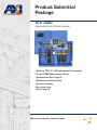
Product Submittal
Package
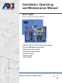
STS 7030
Automated Fuel Filtration System
• Modbus, TCP/IP, LAN and Internet Connectivity
• E-mail & SMS Maintenance Alerts
• Maintenance Alert Log File
• Multiple-tank Functionality
• Runtime Totalizer
• On-screen Help
• Alarm History
Optimal Fuel Quality • Reliable Power
Product Submittal
Package
Section 1
CSI Specifications
Optimal Fuel Quality • Reliable Power
CSI - GUIDE
SPECIFICATION
Possible Sections:
Section 26 32 00 Packaged Generator Assemblies
Section 23 11 13 Facility Fuel Oil Piping
Section 23 13 00 Facility Fuel-Storage Tanks
Section 23 10 00 Facility Fuel Systems
Other sections applicable
Automated Fuel Filtration System
Model: STS 7030
FUEL QUALITY MAINTENANCE SYSTEM
A. Manufacturers: Subject to compliance with requirements, provide product by the following:
1. AXI International
B. Description: Stand-alone, factory complete, automated, programmable, Green Clean Institute Certified,
fuel filtration, optimization and maintenance system shall be provided for each diesel fuel storage tank to
optimize and maintain the condition of fuel stored in that tank. The system shall be capable of eliminating
microbial contamination and removing water, sediment and particulate to comply with ASTM D975
(Standard Specification for diesel Fuel Oils).
1. Enclosure: All system components shall be contained within a powder coated or stainless
steel, weatherproof, outdoor NEMA / UL 50 Type 4 listed enclosure with appropriate ventilation.
Hinged front doors shall be equipped with quarter-turn key lockable handle. Fluid containment
area with leak detection shall be an integral component of the enclosure. Literature pocket
inside enclosure and external enclosure brackets for wall or rack mounting to be included.
2. Plumbing: System shall be furnished with shutoff ball valves on the fuel inlet and fuel outlet for
easy filter / water separator maintenance. A see-through flow indicator shall be installed to
monitor fuel flow and flow rate, both visually and also via the PLC controller. Above mentioned
components shall be located within the enclosure. Internal plumbing will be primarily executed
in stainless steel.
3. Installation: System shall provide male pipe connections protruding from the enclosure for
customer plumbing connection. System shall be located as close as possible to designated fuel
tank. The system’s fuel supply and discharge lines shall be independent and separate from
other fuel lines, with the supply line originating at the lowest point at the bottom of the tank and
the discharge line as far away as possible from the supply line.
4. Filtration / water separation: Four stage filtration / water separation process:
a. Stage 1: Nexus “Y” strainer – 304 Stainless Steel 20 mesh
Filename: CSI STS-7030-New1.docx
9/4/13
Page 1 of 3 Pages
b. Stage 2: LG-X 4000 Fuel Conditioner – to reduce the size and mass of fuel sediments
which naturally form in fuel, and to eliminate microbial contamination thus eliminating the
need for toxic biocides
c. Stage 3: Primary Filtration 10 micron Fine Filter as standard, with water sight-glass and
water drain valve – Cartridges shall be available in 1, 5, 10, and 25 micron ratings
d. Stage 4: Secondary Filtration 10 micron Coalescing Filter as standard, with water sensor
probe and water drain valve – Cartridges shall be available in 1, 5, 10, and 25 micron
ratings in each of three cartridge types: Fine Filter, dissolved and emulsified water
absorbing “WB water block”, and Coalescing
e. Primary and secondary filters shall be equipped with a liquid-filled pressure gauge and
differential pressure indicator
5. Water Sensor: Watect model 550 microcontroller-based water sensor alarm module to
eliminate probe corrosion.
6. Controls / Display functions: System control features, indicator lights and emergency
stop button shall be located on a descriptive external control panel on the front door of the
enclosure for easy operator access. Additional alarm and system status information shall be
displayed inside the system on a full color programmable touch-screen PLC controller,
displayed on a dedicated webpage that monitors the system as well as delivered through Email and SMS messages to designated individuals. System shall provide following control
and display function:
a. Full Modbus TCP/IP and LAN connectivity
b. Programmable Digital Timer – Memory backup to retain program memory during
power outages
c. Pump operating hour counter
d. Pump control switch (Auto-Off-Manual), weatherproof, key operated, front access
e. Alarm Reset - weatherproof push button, external access
f. Power available indicator, green indicator, external display
g. Pump running indicator, amber indicator, external display
h. High vacuum, high pressure, no flow, high water alarm and leak detection, red
indicator, external display
i. Emergency stop push button, red, latching - turn reset, external access
7. Electrical enclosure / Controller: All electrical control features shall be contained within a
separate UL 508A listed industrial control panel located within the mechanical enclosure.
The controller shall monitor the following system alarm points:
a. Leak in enclosure detection (system shutdown)
b. Primary filter high vacuum sensor (system shutdown)
c. Primary filter high water sensor (system shutdown)
d. Secondary filter high pressure sensor (system shutdown)
e. Flow switch (system shutdown after priming delay)
f. External system shut down input
g. Motor Overload (system shutdown)
8. Pump: Positive displacement, internal gear, direct coupled, rotary pump with cast iron housing
and built-in pressure relief bypass valve. Pump flow rate of 30 gallons per minute.
Filename: CSI STS-7030-New1.docx
9/4/13
Page 2 of 3 Pages
9. Motor: UL Listed, TEFC, Thermal overload protection, continuous duty
C. Performance / Design Criteria: System shall be capable of filtering the entire tank volume with a
required filtration run-time of ideally 24 hours, but no more than 48 hours. Sufficient sediment as well as
water-holding capacity should be ensured. System run-time requirements will vary with climate, tanklayout, fuel delivery, refueling intervals, etc. and shall be adjusted in accordance with the input from
pressure and vacuum gauges as well as water sensor.
D. Operation: System shall provide dry contacts for summary alarm and leak detection alarm to interface
with building monitoring or building alarm system. An external shut down feature shall be provided to
interrupt pump operation from a remote location such as a BMS. Additionally, the System may be
remotely controlled by deactivating the PLC Controller timer.
DISCLAIMER STATEMENT
This guide specification is intended for use by a qualified construction Specifier. It is meant to be used in
conjunction with the procedures of each design firm, and the particular requirements of a specific
construction project.
Filename: CSI STS-7030-New1.docx
9/4/13
Page 3 of 3 Pages
Product Submittal
Package
Section 2
Installation, Operation & Maintenance Manual
Optimal Fuel Quality • Reliable Power
Installation, Operating
and Maintenance Manual
STS 7030
Automated Fuel Filtration System
• Modbus, TCP/IP, LAN and Internet Connectivity
• E-mail & SMS Maintenance Alerts
• Maintenance Alert Log File
• Multiple-tank Functionality
• Runtime Totalizer
• On-screen Help
• Alarm History
Optimal Fuel Quality • Reliable Power
2
INSTALLATION, OPERATING AND MAINTENANCE MANUAL
TABLE OF CONTENTS
GENERAL SPECIFICATIONS .................................................................................................................................................. 8 STS 7030 .................................................................................................................................................................................................................................................................. 8 SYSTEM COMPONENTS ......................................................................................................................................................... 8 Y-Strainer ................................................................................................................................................................................................................................................................. 8 Pump / Motor: ..................................................................................................................................................................................................................................................... 8 Fuel Conditioner................................................................................................................................................................................................................................................. 9 Primary Filter ......................................................................................................................................................................................................................................................... 9 Secondary Filter/ Water Separator .......................................................................................................................................................................................................... 9 Weatherproof double door wall-mounted enclosure with lockable handles / latches ........................................................................................ 9 Stainless steel plumbing ............................................................................................................................................................................................................................... 9 PRIMARY INSPECTION ........................................................................................................................................................... 9 Checklist: ................................................................................................................................................................................................................................................................. 9 INSTALLATION.......................................................................................................................................................................... 9 Mounting ............................................................................................................................................................................................................................................................. 10 Electrical................................................................................................................................................................................................................................................................ 10 Plumbing ............................................................................................................................................................................................................................................................. 11 Typical plumbing / Above ground tank installation (schematically) ............................................................................................................................. 12 IMPORTANT INSTALLATION PRECAUTIONS ................................................................................................................12 PRIMING THE SYSTEM..........................................................................................................................................................13 Priming procedure: ........................................................................................................................................................................................................................................ 13 TOUCH-SCREEN CONTROLLER - ALARM FEATURES .................................................................................................14 INITIAL START-UP / COMMISSIONING CHECKLIST ....................................................................................................15 Flow switch setting / adjustment (“No Flow Alarm”) ............................................................................................................................................................... 15 Gauge venting / accuracy ......................................................................................................................................................................................................................... 15 Initial test procedure..................................................................................................................................................................................................................................... 15 OPERATION .............................................................................................................................................................................17 Emergency Stop .............................................................................................................................................................................................................................................. 17 Pump Operation.............................................................................................................................................................................................................................................. 17 SETTING THE CURRENT TIME AND DATE ......................................................................................................................................................................................... 17 PROGRAMMING THE TIMER ..................................................................................................................................................................................................................... 18 Fuel Line Leak.................................................................................................................................................................................................................................................... 18 Stabilizing and Optimizing Fuel Quality ........................................................................................................................................................................................... 18 MAINTENANCE .......................................................................................................................................................................19 Preventative Maintenance ........................................................................................................................................................................................................................ 19 Servicing Y-Strainer........................................................................................................................................................................................................................................ 21 Servicing primary filter................................................................................................................................................................................................................................. 21 Servicing water separator .......................................................................................................................................................................................................................... 22 Servicing secondary filter........................................................................................................................................................................................................................... 22 Changing the secondary filters .............................................................................................................................................................................................................. 22 TROUBLESHOOTING ............................................................................................................................................................23 AUTOMATIC FUEL FILTRATION SYSTEMS WARRANTY ............................................................................................25 LIMITED WARRANTY ............................................................................................................................................................25 TECHNICAL ASSISTANCE AND ORDERING ...................................................................................................................26 Replacement filter elements ................................................................................................................................................................................................................... 26 STS 7030 SYSTEM IDENTIFICATION ................................................................................................................................26 APPENDIX A - ABBREVIATIONS USED IN THIS MANUAL..........................................................................................27 APPENDIX B – DRAWINGS ..................................................................................................................................................28 3
4
STS 7030
Programmable Automated Fuel Filtration System
STS 7030 Programmable Automated Fuel Filtration Systems are self-contained, stand-alone systems that remove
and prevent the buildup of water, sludge and contaminants in tanks. They stabilize diesel and bio-fuels, eliminate microbial contamination to optimize and maintain fuel quality. STS systems guarantee Optimal Fuel Quality for Reliable Power at All Times.
The STS 7000 Series is equipped with a UL508A TouchScreen Controller with Modbus, TCP/IP, LAN and Internet
connectivity for more intuitive system setup and monitoring from remote locations.
STS 7000 Series includes:
• Modbus, TCP/IP, LAN and
Internet connectivity
• E-mail & SMS Maintenance Alerts
• Maintenance Alert Log File
• Multiple tank Functionality
• Runtime Totalizer
• Alarm History
• On-screen Help
STS 7030 SPECIFICATIONS
All STS Systems feature:
• Multi-stage water removal and particulate filtration
• NEMA 12, 13, 4 Powder Coated or Stainless
• UL508A Smart Filtration Controller
• Continuous-Duty Pump, Viton Seals
• Stainless Steel Plumbing
• Stand-Alone, Reliable & Turn-Key
For safe operation, the STS 7000 Series’ Touch-Screen
Controller triggers automatic alarms and shuts down the
pump when filters need service; a leak is detected; high
separator water level, high filter vacuum, or high pump
pressure occurs; or when the fuel flow is out of range.
Implementing STS Fuel Quality Optimization & Maintenance Systems guarantee Optimal Fuel Quality for
Reliable Power At All Times. STS 7000 Series prevents
downtime, periodic tank cleaning, replacing out-of-spec
fuel and fuel-quality related injection system repairs.
Flow Rate
30 GPM
Primary Filter/Water
Separator/Coalescer
1, 5, 10 or 30 µ Particulate
or Coalescing
Secondary Filter/
Water Block
1, 5, 10 or 25 µ Particulate
or Water Block
Fuel Conditioner
LG-X 4000
Smart Filtration
Controller
HMI PLC Controller with Touch-Screen
and remote monitoring, Modbus, TCP/IP
LAN and Internet connectivity
Pump
Internal Gear Pump
Power
208-230V 60Hz 20A or
230V 50Hz 15A
Plumbing
Stainless Steel
Ports
In 2” NPT Out 1.5” NPT
Weatherproof Cabinet
NEMA 12, 13, 4 Powder Coat
or Stainless
Dimensions
56” x 72” x 17”
(142 x 183 x 43 cm)
Weight
≈688 lbs
Not for use with fluids that have a flash point below 100°F.
1-239-690-9589
1-877-425-4239 Toll Free
www.AXI-International.com
Global Fuel Quality Ingenuity
STS 7030 (8/13)
11
Preventive Maintenance Plans for mission-critical power are
essential. However, most service agreements do not cover
fuel-related engine failures. Fuel has a limited shelf-life and
even “fresh fuel” could contain water, sediment, microbes and
bio-fuel components upon delivery.
5
4
6
20
10
17
18
19
To Tank
(Discharge)
Periodic generator tests-runs are too short to determine if fuel 1
quality is adequate for the demands of continuous, full-load
operation. In fact, generator test runs significantly accelerate From Tank
the fuel polymerization and degradation process by returning(Suction)
fuel that has been compromised by heat and pressure back to
the tank.
Potential liabilities can easily be avoided by implementing
an AXI Fuel Quality Maintenance Program as part of every
disaster recovery plan. An STS 7000 automatically maintains
fuel quality and guarantees reliable emergency power
whenever it is needed.
The system is automatically operated by the programmable
UL508A Touch-Screen Controller with Modbus, TCP/IP, LAN
and Internet connectivity. All components and control devices
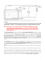
are contained within a fully enclosed, lockable, weatherproof,
NEMA-rated cabinet.
The principal components are a continuous-duty motor with
coupled gear pump, a strainer/primary coalescing filter with
vacuum sensor and gauge, an ALGAE-X Fuel Conditioner and a
secondary water block fine filter with pressure gauge and sensor.
2
3
7
8
9
12
13
14
16
15
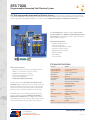
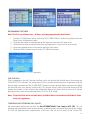
Inside the STS 7030
1. Fuel Inlet (From Tank)
2. Inlet Ball Valve
3. Nexus Y Strainer
4. Vacuum Gauge
5. Vacuum Switch
6. ALGAE-X® Touch-Screen Controller
7. Motor
8. Gear Pump
9. Pressure Relief Valve
10. Pressure Gauge
11. ALGAE-X® Magnetic Fuel Conditioner
12. Leak Deterctor
13. Pressure Transmitter
14. Primary Filter
15. Secondary Filter/Water Separator Coalescer
16. Water Sensor Alarm Module
17. Mechanical Flow Meter with Flow Switch
18. Outlet Ball Valve
19. Fuel Outlet
20. Storage Shelf
STS 7030 Accessories:
• Multiple tank functions
• AFC-705 Fuel Catalyst
• Digital Flow Meter
• Foot Valve
• Wide range of filter elements
The SEPAR primary filter protects the pump, coalesces
and removes water and particulate. The patented ALGAE-X
Fuel Conditioner prevents and reverses fuel degradation,
agglomerization and microbial contamination. The secondary
filter is a quick-change spin-on filter designed to remove
dissolved and emulsified water and contaminants down to 1 µ.
1-239-690-9589
1-877-425-4239 Toll Free
www.AXI-International.com
Global Fuel Quality Ingenuity
11
5
wer are
cover
e and
es and
FJGGVFM
-load
MFSBUF
turning
back to
JOH
every
OUBJOT
4
6
20
10
17
18
19
To Tank
%JTDIBSHF
1
From Tank
(Suction)
2
3
7
8
9
12
13
14
16
15
Inside the STS 7030
1. Fuel Inlet (From Tank)
1) Fuel Inlet (From Tank)
11) AXI® Magnetic Fuel Conditioner
*OMFU#BMM7BMWF
2) Inlet Ball Valve
12) Leak Detector (Float Switch) in Spill Tray
/FYVT:4USBJOFS
3) Nexus Y Strainer
13) Pressure Transmitter
7BDVVN(BVHF
4) Vacuum Gauge
14) Primary Filter
7BDVVN4XJUDI
5) Vacuum Switch
15) Secondary Filter/Water Separator Coalescer
"-("&9¥5PVDI4DSFFO$POUSPMMFS
6) AXI INTERNATIONAL Touch-Screen Controller 16) Water Sensor Alarm Module
7) Motor .PUPS
17) Mechanical Flow Meter with Flow Switch
(FBS1VNQ
8) Gear Pump
18) Outlet Ball Valve
9) Pressure Relief
19) Fuel Outlet
Valve
1SFTTVSF3FMJFG7BMWF
10) PressureGauge
20) Storage Shelf
1SFTTVSF(BVHF
"-("&9¥.BHOFUJD'VFM$POEJUJPOFS
-FBL%FUFSDUPS
1SFTTVSF5SBOTNJUUFS
1SJNBSZ'JMUFS
4FDPOEBSZ'JMUFS8BUFS4FQBSBUPS$PBMFTDFS
8BUFS4FOTPS"MBSN.PEVMF
GENERAL SPECIFICATIONS
STS 7030
Flow Rate ............................................................................... 30 gpm / 1800 gph
14,400 Gallons per 8 hour shift
43,200 Gallons per 24 hours
Outline Dimensions (Enclosure) ............................. 57” x 72” x 14” (H x W x D)
System Weight ................................................................... approx. 510 lbs
Operating Temperature ............................................... 41 to 104° F; 5 to 40° C
Electrical ................................................................................. 208-230 V / 60 Hz / single phase (standard)
...................................................................................................... 230 V / 50 Hz also available
Pump ....................................................................................... Gear Pump
Suction capability (primed) 15 ft vertical or 100 ft. horizontal lift (lines >1”, primed)
Motor ....................................................................................... 2 hp single phase, continuous duty
Timer ........................................................................................ Programmable Digital Timer
Inlet ........................................................................................... 2” NPT male port
Outlet ....................................................................................... 1-1/2” NPT male port
Max. Fluid Viscosity .......................................................... 5 cSt
Note: The STS 7030 is designed to meet environmental standards for safe operation.
(NOT for use with fluids that have a flash point below 100°F (38°C), e.g.: gasoline, alcohol, …)
SYSTEM COMPONENTS
CONTROL AND SAFETY DEVICES
• AXI International “Touch-Screen Controller” in electrical sub enclosure – UL 508A listed Industrial
Control Panel
• Programmable Digital Timer –Memory backup to retain program memory during power outages
• Pump control switch (Auto-Off-Manual), weatherproof, key operated
• Alarm Reset - weatherproof push button
• Power available indicator
• Pump running indicator
• External remote shut-down feature
• Inlet and outlet shut off ball valves
• Emergency stop button
• Pressure relieve valve
• Leak sensor and alarm indicator (system shutdown)
Y-STRAINER
• Nexus Y-Strainer with drain valve
PUMP / MOTOR:
•
•
Positive displacement gear pump
Relief valve
Motor – UL listed
TEFC (Totally enclosed fan cooled)
8
FUEL CONDITIONER
• Inline Algae-X Fuel Conditioner eliminates and prevents microbial contamination and the
formation of sediments that naturally occur in diesel fuel.
PRIMARY FILTER
•
•
•
•
•
RACOR FBO 14 fuel filter
Drain valve on the bottom
Pressure gauge (stainless steel, liquid filled)
10-micron filter cartridge (other filter elements available)
Differential Pressure indicator
SECONDARY FILTER/ WATER SEPARATOR
• RACOR FBO 14 fuel filter / coalescer
• Drain valve on the bottom
• 10-micron filter cartridge (other filter elements available)
• Pressure gauge (stainless steel, liquid filled)
• Differential Pressure indicator
WEATHERPROOF DOUBLE DOOR WALL-MOUNTED ENCLOSURE WITH LOCKABLE HANDLES /
LATCHES
• 14-gauge steel construction with continuously welded seams
• Concealed hinges
• Finished in polyester powder coat inside and out over phosphatized surfaces
• Spill tray with leak detection
• Louvered side panels
• Brackets for wall mounting
• Literature pocket
STAINLESS STEEL PLUMBING
PRIMARY INSPECTION
Upon arrival, the STS 7030 Automatic Fuel Filtration System and accessories must be visually inspected
before installation. Improper handling during shipping may cause physical or electrical problems.
Immediately report or note any damages (also concealed ones) to the shipper.
CHECKLIST:
o If the packing crate shows signs of damage inspect the STS 7030 cabinet for damage. Check the
entire outside of the cabinet for damage that could indicate internal mechanical or electrical
problems.
o Check locking handles, door and hinge operation.
o Check pump/motor hardware and all plumbing connections for tightness.
o Check all electrical terminals and connections for tightness.
INSTALLATION
! IMPORTANT ! It is recommended that only qualified, experienced personnel, familiar
with this type of equipment, who have read and understood all the instructions in this
9
manual should install, operate and maintain the system.
MOUNTING
The STS 7030 is a totally enclosed system and should be permanently wall mounted on a hard, level
surface. Use provided mounting feet for proper fastening. This weatherproof unit is designed for wellventilated indoor or outdoor use within specified temperature range and should be located as close to
the tank as possible.
Please allow about 1 ft of space between the side louvers of the enclosure and nearby objects. This space
is necessary to ensure sufficient ventilation of cooling air for the system and motor.
ELECTRICAL
! WARNING ! To avoid the risk of electric shock make sure that the power supply to the
system is disconnected and ensure that the system is at zero volts, before working on
any of the system’s electrical parts.
Make sure that the systems power requirements and rated voltage / frequency match your electrical
system (See wiring diagram). The STS 7030 may only be connected to properly grounded power sources
for operator safety. Connect all components to the ground studs provided as shown on the electrical
drawings.
! WARNING ! The whole system (Enclosure, doors, plumbing, motor, electric sub panel)
must be properly grounded for operator safety.
Depending on length of run, use copper wiring according to specification in wiring diagram and connect
system to a separate UL listed breaker (not included) appropriate for branch circuit protection.
Note: Wiring and electrical installation must be in accordance with all applicable Federal,
State and Local rules, laws, standards and regulations.
Remote Pump Shut-Down Feature:
If required, connect the “external pump shut down input terminal” (see wiring diagram) and follow
the specifications provided in the electrical wiring diagram to disable pump (e.g.: remote shut down,
remote pump control, …). Please note that the contact needs to be supplied with +24V DC from the
power supply of the STS 7030 AXI International Smart Filtration Controller.
Remote Monitoring - Dry Contacts:
The STS provides two NO (normally open) dry contacts for remote alarm monitoring. Please see wiring
diagram for contact rating, connection and location.
1) “Summary Alarm” – dry alarm contact for high vacuum, high pressure, no flow or water detection
(as well as Emergency stop and overload relay triggered)
2) “Leak Detection” – dry alarm contact for leak detection
10
PLUMBING
Use proper quality approved fuel line materials with at least 2” inner diameter on the suction side
from the tank and at least 1-1/2” inner diameter on the return / discharge side back to the tank.
Note: Do not put any stress on plumbing of STS 7030 and use a backing wrench when
connecting the external plumbing. Whenever possible a FLEXIBLE CONNECTION
SHOULD BE USED TO REDUCE STRESS on the plumbing and prevent damage from
thermal expansion.
The pick-up tube/line(s) should originate from the lowest point of the tank (to remove all water),
should be connected directly to the system’s “PUMP INLET – SUPPLY FROM TANK” port located on the left
hand side of the enclosure and kept as short as possible. It is recommended to install an oversized,
low restriction foot valve to keep the system primed, especially if the “PUMP INLET – SUPPLY FROM
TANK” port of the system is located above the lowest possible fuel level in the tank. A priming tee
should be installed on the highest point of the suction line to be able to easily prime the lines and
system.
The return line(s) should be plumbed to the “PUMP OUTLET – RETURN TO TANK” port (on the right side
of the system) and enter the tank as far as possible from the pick up tube close to the tank bottom. A
(swing) check valve may be required on the return line(s) on some installations to prevent back flow
pressure.
Multiple suction and/or return lines may be connected to a manifold outside the STS 7030 (see options
list).
Anti-Siphon or other external plumbing devices may be required – please check local regulations / code.
The system capabilities are 15 ft suction (vertical) or 100 ft horizontal lift, when connected to (suction)
piping of 2” ID or more with no additional flow restrictions such as valves, 90-degree connectors or other
plumbing accessories. For continuous optimal performance, make sure suction and discharge lines are
free and that nothing is blocking the flow of fuel and that the suction line always stays primed.
11
Note: Plumbing and Installation must be in accordance with all applicable Federal, State and
Local rules, laws, standards and regulations.
TYPICAL PLUMBING / ABOVE GROUND TANK INSTALLATION (SCHEMATICALLY)
IMPORTANT INSTALLATION PRECAUTIONS
The suction line of the system should be independent and separate from the suction line of the
engine. If that is not possible, appropriate valves must be installed to completely separate the STS 7030
from the engine fuel system to prevent any possible interference with safe engine operation.
It is highly recommended to plumb the discharge line independent and separate of the engine’s fuel
return line back to the tank. If the return line from the engine and the discharge of the STS 7030 have to
be combined in any way, adequate valves should be installed to prevent any possible interference with
safe engine operation.
Note: If any of the STS 7030 system’s fuel lines are used in combination with the engine’s fuel
system, the STS 7030 should be disabled during engine operation (use the provided
“remote pump shut down” feature as shown in the electrical drawing and described
above).
12
PRIMING THE SYSTEM
The pump supplied with the STS 7030 is NOT automatically self-priming and must not be run dry.
! WARNING ! If the pump is allowed to run without fuel, pump damage will occur.
The pump head of the STS 7030 unit is shipped from the factory filled with Diesel #2 to facilitate initial
lubrication. This will not eliminate the necessity to prime the complete system. The STS 7030 is primed by
using the externally installed priming tee (not provided) on the suction side of the system. Also the
suction line must be completely filled with fuel prior to the initial system start-up.
PRIMING PROCEDURE:
1. Ensure the pump is filled with #2 Diesel fuel.
2. Ensure that the inlet ball valve is in the open and the outlet ball valve is in the closed position.
3. Slightly open the manual air vent valve (bleed screw) located just below the pressure gauge on
the primary filter(position #14 – page 5).
4. Open the externally installed priming tee (located at the highest point of the suction plumbing),
fill the line with fuel until fuel escapes from bleed screw (manual air vent), close the manual air
vent, continue filling until all air is bled from the plumbing lines and system, close the priming tee.
(for tanks situated on a lower level than the STS 7030, it is recommended that a foot valve is
installed at the fuel tank to hold the fuel column).
5. Make sure to completely fill suction line to its highest point with fuel (no trapped air), in particular
when the suction line exits the tank top and the STS 7030 is located below that level.
6. Open the outlet ball valve and ensure the inlet ball valve is also in open position.
7. Switch on the pump and observe fuel flow.
The system is equipped with a vacuum gauge on the input side of the pump. The gauge should read 0 to
11" HG vacuum maximum under normal conditions. Vacuum gauge readings reaching 12" HG vacuum
indicate excessive debris in the Nexus Y strainer (or a flow restriction or too high suction height and
therefore pressure drop in the suction line) and will result in pump shutdown and activate the alarm
“HIGH VACUUM ALARM”.
Note: 12" HG vacuum = clogged strainer or suction line flow restriction / excessive lift.
The system’s pressure gauge on the secondary filter should show 25 PSI maximum pressure under
normal conditions (.433 PSI = 1' vertical head pressure). Pressure gauge readings in excess of 25 PSI
pressure indicate excessive filter clogging, or fuel line restrictions and/or friction.
Differential pressure over 25 PSI indicates filter clogging (“HIGH PRESSURE ALARM” indicator) and will
automatically shut down the pump.
The pressure relief valve has a 40-45 PSI set point. Pump discharge pressure in excess of 40-45 PSI will
cause the pressure relief valve to open and vent fuel back to the fuel transfer pump inlet side.
TOUCH-SCREEN CONTROLLER - ALARM FEATURES
The STS 7030 is equipped with an AXI INTERNATIONAL Touch-Screen Controller. System and alarm
status are displayed on the industrial control panel (on the door) via indicator lights and on the text
display directly on the controller.
14
INITIAL START-UP / COMMISSIONING CHECKLIST
FLOW SWITCH SETTING / ADJUSTMENT (“NO FLOW ALARM”)
Note: Flow switch needs to be adjusted to actual flow rate for proper system operation.
Please make sure system is properly primed and check when pump running for a steady stream of fuel
without air bubbles in the mechanical flow meter (indicator) inside the STS 7030 enclosure. If the “NO
FLOW ALARM” alarm light is blinking (and after 10 seconds illuminate continuously as the pump is turned
off) the flow switch located on the side of the mechanical flow meter needs to be adjusted to the
actual flow rate.
This can be easily done by sliding the black switch (with lead attached) located on the side of the sight
glass carefully up or down (while pump is running) and lining up the flow switch with the indicator ring
inside the sight tube of the flow meter showing the actual flow rate. For further information please see
enclosed instruction sheet.
You can reset the alarm by pushing the “ALARM RESET” button located on the control panel.
GAUGE VENTING / ACCURACY
After shipment, pointer of gauges may not rest at zero due to internal case pressure buildup caused by
temperature variations. Accuracy may be significantly reduced. To restore gauge to operating
condition, move yellow lever of fill plug to the ”open” position or remove small plug from top of
gauge and leave open.
INITIAL TEST PROCEDURE
o With breakers and power turned on and pump running check all alarms for proper operation:
1. Manually raise float switch located in drip/spill tray. Pump should immediately turn off and “LEAK
DETECTION” should illuminate. Reset alarm by pushing the “RESET ALARM” button on the control
panel.
2. Slowly partially close inlet ball valve. At 12”HG pump should turn off and “HIGH VACUUM ALARM”
should illuminate. Open inlet ball valve again. Reset alarm by pushing the “RESET ALARM” button.
3. Slide the flow switch located on the side of the mechanical flow meter slightly upwards away
from the flow indicator inside the sight tube (mark original position before doing so). The “NO
FLOW ALARM” indicator should start blinking for 10 seconds and then illuminate constantly as the
pump is turned off. Slide flow switch back into original position and reset alarm by pushing the
“RESET ALARM” button.
Note: If any of the above described alarm test procedures fail or if any alarm trip value
deviates immediately contact AXI International.
OPERATION
`
`
! WARNING ! Do not use with gasoline. This System is not meant for use with gasoline
nor with other flammable liquids having a flash point less than 100°F. Use with gasoline
or use with any flammable liquids at a temperature exceeding their flash point,
presents an immediate explosion and fire hazard.
! WARNING ! Never use the STS 7030 at a temperature exceeding the flash point of its
contents.
EMERGENCY STOP
Note: In case of an emergency the pump can be turned off and disabled by depressing the red
“EMERGENCY STOP” button on the control panel.
To release the “EMERGENCY STOP” button located on the control panel turn the red knob in the direction
indicated by the arrows on the mushroom button and push the “ALARM RESET” button to acknowledge.
PUMP OPERATION
Apply control power to unit. Place breakers in the AXI International Smart Filtration Controller in the “ON”
position.
Automatic:
Place the key switch in the “AUTO” position. When the timer contacts close, the pump will start and run
until the timer setting has expired.
Manual (Override):
Place the key switch in the “RUN” position. The pump motor will run until the switch is returned to the
“OFF” or “AUTO” mode positions or till an alarm or overload has been tripped.
SETTING THE CURRENT TIME AND DATE
Note: PLC uses military time – all times must be programmed in that format.
1. From the STS 7004 Home Screen, touch and hold the screen background for 5 seconds to enter
the Info Mode Menu.
2. Touch the “Enter Info Mode” button.
3. Enter 4 digit security code.
4. Touch the “Time & Date” button.
5. Touch the Date value to set the Date. Use dd/mm/yy format.
6. Touch the Time value to set the current time.
7. Press ESC to navigate back to the STS 7004 Home Screen.
PROGRAMMING THE TIMER
Note: The PLC uses military time – all times must be programmed in that format.
1. From the STS 7004 Home Screen, touch the “AUTO TIMER CONFIG” screen to navigate to the Auto
Pump Timer Configuration Screen.
2. Touch the day button to select the day of the week you want the Auto Timer to run.
3. Touch the time values to set the Pump Start and Stop times in Auto (use 24hr time format.)
4. Up to three separate timers can be set for each day of the week.
5. Touch the “Menu” button to return to the STS 7004 Home Screen.
Please call AXI International with any questions.
FUEL LINE LEAK
If fuel is detected in the spill / drip tray, the float switch will activate the fuel leak alarm, illuminating the
“LEAK DETECTION” indicator. The pump motor will shut off and remain locked out of operation until the
leak has been corrected and the “ALARM RESET” button has been pushed. Before removing the spilled
fuel from the basin, turn the key switch to the “OFF” position. Always make sure to find the cause of the
leakage and correct it. After removing the spilled fuel, allowing the leak switch to return to its normal
position, the key switch can be returned to the “AUTO” or “RUN” mode.
Note: Disposal of fuel and associated waste should be done in accordance with Federal, State
and Local regulations.
STABILIZING AND OPTIMIZING FUEL QUALITY
We recommend treating the fuel with the AXI INTERNATIONAL Fuel Catalyst (AFC-705). This will
enhance and accelerate the tank cleaning process by breaking down and dissolving existing tank sludge.
AFC-705 will decontaminate compartments of the tank that are out of reach of the suction line.
18
Depending on the condition of the fuel and the amount of sludge build-up, it is recommended to initially
use a double dose of one to twenty-five hundred (1:2500) instead of one to five thousand (1:5000) This
has proven to be essential in accelerating the tank cleaning process. AFC-705 contains detergent,
surfactant, dispersant, corrosion inhibitor, lubricity enhancer and combustion catalyst. It does not contain
biocides. AFC-705 should always be used periodically in particular to stabilize fuel that is stored for longer
periods of time.
Note: In cases of severe tank contaminant build-up (sludge) and high water level in bottom, it
is recommended to clean the tank (vacuum bottom) and polish the fuel before initial
use of an STS system.
MAINTENANCE
! IMPORTANT ! It is recommended that only qualified, experienced personnel, familiar
with this equipment, who have read and understood all the instructions in this manual
should install, operate and maintain the system.
`
! IMPORTANT ! Always disconnect the system from the electric power supply before
working or servicing it. Do not proceed with any maintenance unless the pressure or
vacuum has been released, the system has been allowed to reach ambient temperature
and all fluids have been drained.
PREVENTATIVE MAINTENANCE
The STS 7030 Automatic Fuel Filtration System should be visually inspected and tested a minimum of
every six months according to the procedure below during light duty cycles. Monthly inspections are
recommended for systems that are being used in excess of an average of 8 hours day and five days a week.
o Prior to performing the maintenance procedure ensure that:
1. The electrical sub-panel mounted main disconnect switch is operating properly,
2. the user supplied remote circuit breaker is in the “Off” position, and
3. All sources of power are isolated from the unit.
4. Proceed only after this has been verified and properly tagged.
o Drain visible water and sediment from primary filter / water separator (see Servicing Primary Filter
/ Water Separator below).
o Check enclosure and all parts for corrosion and rust.
o Check locking latches, door and hinge operation.
o Check cabinet mounting hardware. Tighten as necessary.
o Check pump/motor hardware for tightness. Pump/motor hardware will loosen after normal
operation due to vibration. This hardware is lock nutted, check all bolts for secure nuts.
o Check all electrical terminals and connections for tightness.
o All motors are permanently lubricated and do not require any lubrication.
o All pumps are self-lubricating and do not require any maintenance.
o Check all plumbing joints for leaks. Tighten fittings and joints as necessary. Remove accumulated
fuel in drip tray as necessary.
o Inspect all filters and separators. See section below on filter inspection and service.
o With breakers and power turned on again and pump running check all alarms for proper operation:
1. Manually raise float switch located in drip/spill tray. Pump should immediately turn off and
“LEAK DETECTION” should illuminate. Reset alarm by pushing the “RESET ALARM” button on
the control panel.
2. Slowly partially close inlet ball valve. At 12”HG pump should turn off and “HIGH VACUUM
ALARM” should illuminate. Open inlet ball valve again. Reset alarm by pushing the “RESET
ALARM” button.
19
3. Slide the flow switch located on the side of the mechanical flow meter slightly upwards away
from the flow indicator inside the sight tube (mark original position before doing so). The “NO
FLOW ALARM” indicator should start blinking for 10 seconds and then illuminate constantly as
the pump is turned off. Slide flow switch back into original position and reset alarm by
pushing the “RESET ALARM” button.
Note: If any of the above described alarm test procedures fail or if any alarm trip value
deviates immediately contact AXI International.
Note: All filter elements should be replaced at least every six months.
20
SERVICING Y-STRAINER
Excessive debris in the Nexus Y strainer will result in pump shutdown and activate the alarm “HIGH
VACUUM ALARM”. This indicates that it is time to clean the strainer basket.
Servicing Y-Strainer:
1. Turn key switch to the “OFF” position – make sure pump will not turn on
2. Close the inlet and outlet ball valve
3. Place a fuel waste container below the drain valve on the bottom of the Y-Strainer
4. Open the drain valve
5. Allow all fluid to drain from the Y-Strainer
6. Using an adjustable wrench, unscrew the brass cap on the bottom of the Y-Strainer
7. Remove the strainer basket, clean and replace
8. Replace the brass cap, tighten securely
9. Close the drain valve
10. Open the inlet and outlet valves
11. Push the “ALARM RESET” button on the control panel to acknowledge the alarm and reset it
12. Return the pump selector key switch to “AUTO” or “RUN”
SERVICING PRIMARY FILTER
The gauge will indicate maximum pressure during system operation.
Clogging filter elements restrict the flow of fuel and the system’s pressure gauge will indicate a pressure drop.
The gauge is mounted on top of the primary filter. At a differential pressure drop of 25 psi, the pump will
automatically shut off and activate the “HIGH PRESSURE ALARM” indicator light. The signal indicates that it is
time to change the filter element. There are several types of filters available; the STS 7030 30GPM is shipped
with a factory installed 10 micron Micro Filter element in the primary filter.
Servicing primary filter:
1. Turn key switch to the “OFF” position – make sure pump will not turn on
2. Close the inlet and outlet ball valve
3. Place a fuel waste container below the drain valve on the bottom of the filter
4. Open the drain valve
5. Allow all fluid to drain from the filter
6. Open the vent valve on the cover of the housing ; allow the unit to thoroughly vent before
7. opening the cover
8. Loosen the 4 knobs attaching the head to the housing flange
9. Remove the head gasket and discard
10. Remove and discard the expended cartridge in a FIRE-SAFE place. In accordance with local and
national regulations.
11. Flush the interior of the housing with clean, processed, filtered product or a suitable solvent. A
nonmetallic bristle brush will help to remove caked-on debris. Rinse the housing and unit cover
with a clean solvent and dry with soft, lint-free wiping cloths.
12. Lightly lubricate new head gasket with Vaseline or Petroleum Jelly and position it on the head. If
Vaseline is not available lubricate the gasket with the fuel or oil it will be used in.
21
13. Insert a new cartridge into the housing. Position housing (with cartridge) underneath filter head.
Push/twist cartridge onto head spigot. The head “conical spring” will seat/seal the cartridge in the
housing.
14. “Rotate” housing onto the collar bolts, hand tighten knobs until head is “snug” to housing.
Note: A torque wrench is recommended. Tighten all collar bolts to 100 in lbs.
1.
2.
3.
4.
5.
Close the drain valve on the bottom of the housing.
SLOWLY open the inlet and outlet valves; allow the unit to fill completely.
Leave the vent valve on top of the unit open; to allow entrapped air to escape while filling.
When a small amount of fluid flows from the vent, close it tightly.
During the initial filling and after the above maintenance, and while unit is in operation, examine
housing and all connections for leaks. Including head/flange junction.
6. Push the “ALARM RESET” button on the control panel to acknowledge the alarm and reset it
7. Return the pump selector key switch to “AUTO” or “RUN”
8. Check for leaks when re-starting and pressurizing the system. Your system is now ready to resume
normal operation
SERVICING WATER SEPARATOR
If the water level in the secondary filter/water coalescer reaches a certain level in the bowl, the water
sensor will trigger the alarm “HIGH WATER ALARM” and shut off the pump. The signal indicates that it is
time to drain the bowl on the secondary filter.
SERVICING SECONDARY FILTER
Clogging filter elements restrict the flow of fuel and the system’s pressure gauge will indicate a pressure
drop.
The gauge and differential pressure indicator are mounted on top of the secondary filter head. At a
differential pressure drop of 25 PSI (red dial area of the gauge) the pump will automatically shut off and
activate the “HIGH PRESSURE ALARM” indicator light. The signal indicates that it is time to change the
filter element.
There are several types of filters available; the STS 7030 30GPM is shipped with a factory installed 10
micron Filter Separator coalescing element.
CHANGING THE SECONDARY FILTERS
See Servicing primary filter instructions above
Note: Disposal of fuel, associated waste and filters should be done in accordance with Federal,
State and Local regulations.
`
! WARNING ! Some fuels may have been treated with biocides. Biocides are extremely
toxic and may enter the body through the skin. It is recommended to use adequate
protection and proper precautions if fuel contains biocide type products.
22
TROUBLESHOOTING
No fuel delivery
1. Pump does not run
2. Pump is not primed
3. Fuel supply line blocked
4. Excessive lift
5. Air leak in fuel supply to pump
6. Pump rotation direction incorrect
7. Intake or outlet valve closed
8. Check valve installed backwards
Insufficient fuel delivered
1. Air leak at inlet
2. Defective pressure relief valve or check valve
3. Excessive lift
4. Pump worn
5. Inoperative foot valve
6. Piping improperly installed or dimensioned
7. Primary filter/water separator plugged
Rapid pump wear
1. Pipe strain on pump causing bind
2. Worn pump/motor coupler
3. Pump has been run dry or with insufficient fuel
4. Plumbing on inlet side not appropriately dimensioned
Alarm “HIGH VACUUM ALARM” comes on with clean strainer element installed
1. Heavily contaminated fuel / excessive water in tank
2. Restriction in plumbing on inlet side too high
3. Excessive lift
4. Inoperative foot valve
5. Inlet ball valve not fully open
6. Suction line clogged
Alarm “HIGH PRESSURE ALARM” comes on with clean or new filter elements installed
1. Heavily contaminated fuel / excessive water in tank
2. Restriction in plumbing on discharge side too high
3. Head (lift) on discharge side too high
4. Check valve stuck or defective
5. Outlet ball valve not fully open
6. Discharge line clogged
Pump requires too much power
1. Air in plumbing lines
2. Liquid too viscous
3. Bent pump shaft, binding rotor
Noisy operation
1. Insufficient fuel supply
2. Air leaks in the inlet pipe
3. Air or gas in fuel on the suction side
4. Worn out spider coupling
23
5. Pump coupler out of balance
Pump requires frequent re-priming
1. Inoperative foot valve
2. Inoperative check valve
3. Inoperative solenoid valve (optional)
4. Pump cavitations
5. Plumbing air leaks
6. Lift too high
7. Leaking pump seal
Motor does not turn or turns intermittently
1. Control power not available
2. Motor thermal overload condition
3. Pump failed and seized
4. Motor failure
5. Emergency Button depressed
Pump leaks fuel
1. Loose pump plumbing fittings
2. Worn pump shaft seal
3. Pump pressure relief valve failure
4. Fuel leak elsewhere and fuel dripping or running towards the pump
5. Excessive head from overhead storage tank
6. Worn pump O-rings or seals
24
AUTOMATIC FUEL FILTRATION SYSTEMS WARRANTY
LIMITED WARRANTY
AXI International makes every effort to assure that its products meet high quality and durability standards and
expressly warrants the products described herein, against defects in material and workmanship for a period of one
(1) year from the date of purchase. This warranty is not intended to supplant normal inspection, care and service of
the products covered by the user, and shall not obligate AXI INTERNATIONAL to provide free service during the
warranty period to correct breakage, maladjustment or other difficulties arising out of abuse, misuse, or improper
care and maintenance of such products. Our express warranty is subject to the following terms and conditions:
1. This warranty shall only extend to and is only for the benefit of original purchasers who use the products
covered hereby
2. Any warranty claim received by AXI INTERNATIONAL after one (1) year from the date of purchase will not be
honored even if it is claimed that the defect occurred prior to one (1) year from the date of purchase.
3. This warranty shall not apply to products (1) which have been tampered with, altered or repaired by anyone
other than AXI INTERNATIONAL without the express prior written consent of AXI INTERNATIONAL (2) which
have been installed improperly or subject to misuse, abuse, accident, negligence of others, improper operation
or maintenance, neglect or modification, or (3) which have had the serial number altered, defaced or removed.
4. The liability of AXI INTERNATIONAL under this warranty is limited to the repair or replacement of the defective
product. AXI INTERNATIONAL assumes NO LIABILITY for labor charges or other costs incurred by any purchaser
incidental to the service, adjustment, repair, return, removal or replacement of products. AXI INTERNATIONAL
ASSUMES NO LIABILITY FOR ANY GENERAL, SPECIAL, INCIDENTAL, CONSEQUENTIAL, CONTINGENT OR OTHER
DAMAGES UNDER ANY WARRANTY, EXPRESS OR IMPLIED, AND ALL SUCH LIABILITY IS HEREBY EXPRESSLY
EXCLUDED.
5.
AXI INTERNATIONAL MAKES NO WARRANTIES, EXPRESS OR IMPLIED, OF MERCHANTABILITY, FITNESS FOR A
PARTICULAR PURPOSE OR OTHERWISE, WITH RESPECT TO THE PRODUCTS COVERED BY THIS WARRANTY POLICY,
EXCEPT AS EXPRESSLY PROVIDED FOR HEREIN. NO EMPLOYEE, AGENT, REPRESENTATIVE OR DISTRIBUTOR IS
AUTHORIZED TO MAKE ANY WARRANTY ON BEHALF OF AXI INTERNATIONAL OTHER THAN THE EXPRESS
WARRANTY PROVIDED FOR HEREIN.
6. AXI INTERNATIONAL reserves the right at any time to make changes in the design, material, function and
specifications of its products. Any such changes shall not obligate AXI INTERNATIONAL to make similar
changes in such products that were previously manufactured.
WARRANTY CLAIM PROCEDURE
To make a claim under this warranty, please call our AXI INTERNATIONAL at (239) 690 9589 or (877) 425-4239, and
provide: Name and location where unit was purchased, the date and receipt of purchase, model number, serial
number, and a detailed explanation of the problem you are experiencing. The Customer Service Representative
may, at the discretion of AXI INTERNATIONAL, arrange for a Field Engineer to inspect your system. If the inspection
discloses a defect covered by its limited warranty, AXI INTERNATIONAL will either repair or replace the defective
parts or products. AXI INTERNATIONAL assumes no liability, if upon inspection, AXI INTERNATIONAL or its
representative determines that there is no defect or that the damage to the system resulted from causes not
within the scope of this limited warranty. For service and sales, please contact AXI INTERNATIONAL:
AXI International
5400 Division Drive, Fort Myers, FL 33905 • 877-425-4239 • Fax: 239-690-1195
Internet: www.axi-international.com • Email: [email protected]
25
TECHNICAL ASSISTANCE AND ORDERING
Please write, fax, email or call:
AXI International International
5400 Division Drive
Fort Myers, FL 33905
Tel: 239-690-9589
Fax: 239-690-1195
Email: [email protected]
Internet: www.axi-international.com
Please provide the following information:
Serial Number of your STS 7030, the required part numbers and quantity. The drawings / parts list
included in this manual are the most accurate source of part numbers for your STS 7030.
REPLACEMENT FILTER ELEMENTS
Primary Filter:
FBO-60339 Micro filter element - 1 Micron
FBO-60340 Micro filter element - 5 Micron
FBO-60357 Micro filter element - 10 Micron
FBO-60341 Micro filter element - 25 Micron
Secondary Filter:
FBO-60336 Coalescing filter element - 1 Micron
FBO-60337 Coalescing filter element - 5 Micron
FBO-60356 Coalescing filter element - 10 Micron
FBO-60338 Coalescing filter element - 25 Micron
Also available:
• Larger or smaller capacity, custom designed systems for higher or lower flow rates
• Digital Flow Meter
• Foot Valves
• Rotor Sight Glass
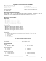
STS 7030 SYSTEM IDENTIFICATION
Serial Number: __________________________ (e.g. B 070010 – 6100)
System Specification:
Voltage:
o 208-230 V AC / 60 Hz
o 230 V AC / 50 Hz
Primary Filter Element:
o 1 Micron
o 5 Micron
o 10 Micron
o 25 Micron
Secondary Filter Element:
o 1 Micron Coalescing
o 5 Micron Coalescing
o 10 Micron Coalescing
o 25 Micron Coalescing
Inspected by: ______________________________
Date: ________________
26
APPENDIX A - ABBREVIATIONS USED IN THIS MANUAL
Abbreviations of terms used with STS 7030 Automatic Fuel Filtration Systems. When following a drawing
utilize this guide to define abbreviated system and component names. This is a master list. The drawings
and text pertaining to your equipment may not contain all these terms.
AC
AHR
AH
BPRV
BRK
BV
C
CB
CSR
CV
DC
DPDT
F
FLWS
FS
GA
GAL
GPM
HFL
HG
HP
HZ
I.D.
JB
“ HG
L
L.E.D.
LFF
LFL
LPR
MDB
MDS
MOT
Alternating Current
Alarm Horn Relay
Alarm Horn
Back Pressure Regulating Valve
Motor/Pump Bracket
Ball Valve
Contactor
Circuit Breaker
Check Strainer Relay
Check Valve
Direct Current
Double Pole Double Throw
Fuse
Flow switch
Float switch
Gauge
Gallons
Gallons Per Minute
High Fuel Level Relay
Mercury
Horsepower
Hertz
Inside Diameter
Junction Box
Inches of Mercury
Lamp
Light Emitting Diode
Loss of Flow Relay
Low Fuel Level Relay
Low Pressure Relay
Main Distribution Block
Main Disconnect Switch
Motor
N.C.
NEC
NEMA
N.O.
NP
NPT
O.D.
OLR
OPT
PCB
PCRX
PG
PLR
PRV
PRS
PS
PSI
PSR
PRR
SC
SOL
TB
T
TDR
TEFC
THR
TS
V
VAC
VDC
VG
Normally Closed
National Electric Code
National Electric Manufacturers Assoc.
Normally Open
Nameplate
National Pipe Thread
Outside Diameter
Over Load Relay
Option
Printed Circuit Board
Pump Control Relays
Pressure Gauge
Pipe Leak Relay
Pressure Relief Valve
Pressure Switch
Power Supply
Pounds Per Square Inch
Pressure Switch Relay
Pump Running Relay
Swing Check Valve
Solenoid
Terminal Block
Control Transformer
Time Delay Relay
Totally Enclosed, Fan Cooled
Tank Heater Control Relay
Transducer Pressure Switch
Voltage
Voltage, Alternating Current
Voltage, Direct Current
Vacuum Gauge
27
APPENDIX B – DRAWINGS
28
Product Submittal
Package
Section 3
Electrical Drawing
Optimal Fuel Quality • Reliable Power
Product Submittal
Package
Section 4
Installation Notes & Recommendations
for Site and/or Tank Plumbing
Optimal Fuel Quality • Reliable Power
There are no additional installation notes or recommendations.
Please see the product manual included in this submittal for installation information.
AXI designs and manufactures standardized and custom-engineered
Automated Fuel Conditioning, Fuel Polishing and Transfer Systems,
Tank Cleaning Equipment, Fuel Additives and In-line Fuel Conditioners
to ensure optimal fuel quality at all times.
Our scope of expertise covers fuel storage and fuel supply systems
from single engine installations to power plants. AXI is your single
source for all fuel conditioning related equipment and support
available world-wide.
• Peak Engine Performance
• Reliable Power Supply
• Lower Maintenance Costs
• Lower Exhaust Emissions
Read about the secret life of
fuel and find solutions in the
AXI Brochure, available at
www.AXI-International.com
See the full product line in the
AXI Systems and Equipment
Catalogue, available at
www.AXI-International.com
AXI International
5400 Division Drive
Fort Myers, FL 33905
1 877-425-4239
1 239-690-9589
www.AXI-International.com
©Copyright 2013 AXI International