1
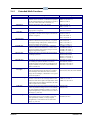
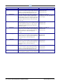
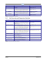
DO1-DO8 Trigger
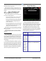
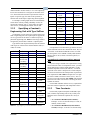
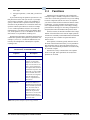
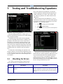
If any of the DO1-DO8 Type fields were set up as oneshot outputs, choose the method the Flexible Combiner
will use to generate pulses. The choices are:
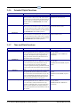
• Edge - Pulse is generated when the application transitions the output from OFF to ON.
of each input you defined (AI1-AI8 and DI1-DI8). These
names are the ones that are used when building equations.
When finished, press B to proceed to the Outputs
screen.
1.3.1.4
Outputs
• Inv Edge - Pulse is generated when the application
transitions the output from ON to OFF.
• Both Edge - Pulse is generated every time a state
transition occurs, whether it is OFF to ON or ON to
OFF.
Press B to proceed to the Inputs screen.
1.3.1.3
Inputs
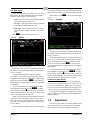
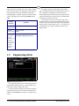
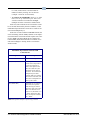
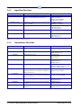
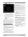
Figure 1-4 - Flexible Combiner Outputs
The Outputs screen will show the output definitions for
the number of analog and digital outputs you specified in
Screen 1: General.
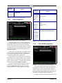
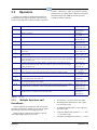
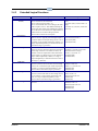
Figure 1-3 - Flexible Combiner Inputs
The Inputs screen will show the input definitions for
the number of analog and digital inputs you specified in
Screen 1: General.
The default input format is “Controller:Application:Output.” If you wish to use the output from another
E2 application as an input for the Flexible Combiner application, use the Look-Up Table (D) to select the controller, application name, and output name for each field in
the definition.
If you want an input to be a board and point address
from a MultiFlex input board, press C to change
the I/O format, and select from the menu to change the
format to Board and Point. Then, enter the board and point
address of the input point in each field.
NOTE: If a point you enter in this manner has not been
configured yet from the Input Summary screen, you will
need to do so before entering its board and point address
here. Refer to the E2 User’s Manual (CPC P/N 026-1610)
for more details.
Once all inputs are defined, make a note of the names
Equations
The default output format is “Controller: Application:
Input.” If you wish to use the input of another E2 application as the destination for a Flexible Combiner’s output
value, use the Look-Up Table (D) to select the controller, application name, and input name for each field in
the definition.
If you want an output to be a board and point address
from a MultiFlex output board, press C to change
the I/O format, and select from the menu to change the
format to Board and Point. Then, enter the board and point
address of the relay or analog point in each field.
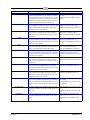
ON DELAY and OFF DELAY
Each digital output will have two corresponding outputs, one for its on delay and one for its off delay. It is not
necessary to configure these outputs. They are only there
so the value of the on and off delays may be logged, used
in generic alarm control, and presented in status screens.
Once all inputs and outputs are configured, you will be
ready to complete the Flexible Combiner programming by
building equations.
1.4
Equations
The value of each output in a Flexible Combiner application is determined by its own equation, which usually
takes the values of one or more inputs and performs a
Equations • 1-3