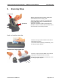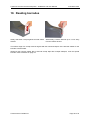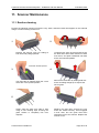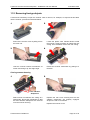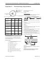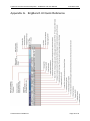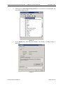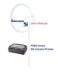
1
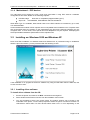
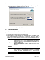
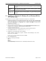
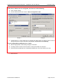
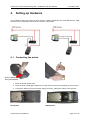
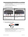
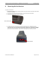
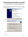
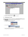
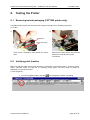
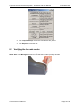
Cyberview Technology Ltd. www.cybview.com Greyscale Scanner CST 5000 Thermal Printer CST 7000 & 7001 Installation and User Manual Commercial-in-Confidence print&scan_user_414 Cyberview scanner and thermal printer - Installation and User Manual 15 October 2007 Copyright ® © Cyberview Technology Limited 2007 This document has been prepared by Cyberview Technology Limited and, subject to any existing agreements or rights of other parties; Cyberview Technology Limited is the owner of the copyright of this document. The contents may not be copied or disclosed to a third party without permission in writing from Cyberview Technology Limited, nor may it be used for any purpose other than that for which it has been supplied. Cyberview believes that the information in this document is accurate at the date of release but accepts no responsibility for any loss or other consequence arising from omissions or inaccuracies contained herein. The information in this document is subject to change. Revisions and updates will be issued from time to time to document changes and/or additions. The following are trademarks, registered trademarks or service marks of Cyberview Technology Limited, Cyberscan Technology Inc, and Cyberview Technology Inc in the United Kingdom, other countries, or both: Cyberview, Cyberscan, Doubloon Lagoon, Golden Track, Cash Cracker, Golden Saddle, Championship Penalty, King‟s Crown, CrackerJack Jackpot, Maya, Wild Spin, Mia, Lara, Prima, Diamond Dice, Winning Goal, Maxi, Firefly. Microsoft, Windows, Windows NT, and the Windows logo are trademarks of Microsoft Corporation in the United States, other countries, or both. Microsoft product screen shot(s) reprinted with permission from Microsoft Corporation. Java and all Java-based trademarks and logos are trademarks or registered trademarks of Sun Microsystems Inc. in the United States and other countries. Intel, Pentium, Xeon are trademarks or registered trademarks of Intel Corporation or its subsidiaries in the United States and other countries. Other company product names mentioned herein may be trademarks or registered trademarks of their respective owners and should be noted as such. Commercial-in-Confidence Page 2 of 43 Cyberview scanner and thermal printer - Installation and User Manual 15 October 2007 Table of Contents 1. Preface ......................................................................................................................................... 5 1.1 Who should read this guide ................................................................................................ 5 1.2 Related documents ............................................................................................................. 5 2. Hardware ...................................................................................................................................... 6 3. Installing Printer and Scanner Software ................................................................................... 7 3.1 3.2 3.3 4. Supported platforms ............................................................................................................ 7 3.1.1 Processor requirements .......................................................................................... 7 3.1.2 Memory ................................................................................................................... 7 3.1.3 Minimum specification ............................................................................................. 7 3.1.4 Motherboard – ECP devices ................................................................................... 8 Installing on: Windows 2000 and Windows XP ................................................................... 8 3.2.1 Installing driver software ......................................................................................... 8 3.2.2 Installing SDK software ......................................................................................... 10 Installing on: Windows 95, Windows 98, and Windows ME (for ECP devices only) ........ 11 Setting-up Hardware ................................................................................................................. 13 4.1 Connecting the printer ....................................................................................................... 13 4.2 Connecting the scanner .................................................................................................... 14 2.3 Connecting the power supply............................................................................................ 14 5. Powering-On the Devices ......................................................................................................... 15 6. Completing the Driver Installation (USB devices) ................................................................. 16 7. Scanner Functional Verification .............................................................................................. 18 8. 7.1 Installing EngBench .......................................................................................................... 18 7.2 Testing the scanner .......................................................................................................... 18 7.3 Calibrating the scanner ..................................................................................................... 19 7.4 Verifying scanner operation .............................................................................................. 20 Testing the Printer..................................................................................................................... 22 8.1 Removing transit packaging (CST7000 printer only) ........................................................ 22 8.2 Verifying print function ...................................................................................................... 22 8.3 Verifying the barcode reader............................................................................................. 23 9. Scanning Slips ........................................................................................................................... 24 10. Reading barcodes ..................................................................................................................... 25 11. Scanner Maintenance ............................................................................................................... 26 12. 11.1 Routine cleaning .............................................................................................................. 26 11.2 Removing foreign objects ................................................................................................ 27 Printer Maintenance .................................................................................................................. 28 12.1 Changing printer paper: CST7000 printer ....................................................................... 28 Cyberview scanner and thermal printer - Installation and User Manual 12.2 15 October 2007 Changing printer paper: CST7001 printer ....................................................................... 30 Appendix A. Safety Instructions Appendix B. Barcode Default Resets ............................................................................................. 33 Appendix C. CST5000 HIGH PERFORMANCE GREYSCALE SCANNER .................................... 35 Appendix D. CST7000 High Capacity Thermal Printer Specification .......................................... 36 Appendix E. CST7001 High Capacity Thermal Printer Specification .......................................... 37 Appendix F. Thermal Paper Specification ..................................................................................... 38 Appendix G. EngBench UI Quick Reference ................................................................................. 39 Appendix H. Manual Driver Installation ......................................................................................... 40 Commercial-in-Confidence ............................................................................................. 32 Page 4 of 43 Cyberview scanner and thermal printer - Installation and User Manual 1. 15 October 2007 Preface This document contains details on: Installing Cyberview printer and scanner driver software, Installing the Cyberview printer and scanner SDK files, Setting up printer and scanner hardware, Using the printer and scanner. The configuration methods discussed in this document have been tested and approved by Cyberview. Configurations other than those detailed in this document may result in system malfunction. Contact Cyberview for advice on implementing configurations other than those detailed in this document. IMPORTANT 1.1 Cyberview cannot accept responsibility for component malfunctions resulting from configurations different to those detailed in this document if the changes were not first discussed with Cyberview. Who should read this guide This guide is for installation engineers responsibly for the installation and maintenance of Cyberview printers and scanners. 1.2 Related documents Cyberview Greyscale Scanner and Thermal Printer Software Interface Specification. This document contains information on installing the printer and scanner software development kit, and using it to create applications for the devices. Cyberview Greyscale and Thermal Printer – Creating Betting Forms This document details the method for creating active betting slips that when scanned can automatically record customer bets. Commercial-in-Confidence Page 5 of 43 Cyberview scanner and thermal printer - Installation and User Manual 2. 15 October 2007 Hardware Cyberview printer and scanners: Device Model number Connector type Scanner CST 5000-20001 ECP Scanner CST 5000-20002 USB Epson printer CST 7000-00002 ECP Epson printer CST 7000-00003 USB XAC printer CST 7001-00003 ECP XAC printer CST 7001-00004 USB Image Connectors and accessories: Item Details New power supply C5 clover leaf power connector with Kycon KPP 4 pin connectors. The new power pack has an improved power ratio that allows images to be printed and scanned at the same time. Legacy power supply Figure-of-eight female power connector with DB9 connectors. Power adapter DB9 to Kycon KPP adapter – for connecting ECP devices to power supply. USB connector Product code CST 9002. Printer/scanner to PC USB connector. This is the device to PC connector for USB devices. Commercial-in-Confidence Image Page 6 of 43 Cyberview scanner and thermal printer - Installation and User Manual 3. Installing Printer and Scanner Software 3.1 Supported platforms 15 October 2007 For simplicity, throughout this document the two types of supported scanner and printer are referred to as: ECP printer and ECP scanner, and USB printer and USB scanner depending on the device‟s connection type. Platform support for the ECP printer and scanner drivers ® ® Microsoft Windows 95 Microsoft Windows 98 Microsoft Windows ME Microsoft Windows 2000 Microsoft Windows XP. Platform support for the USB printer and scanner drivers Microsoft Windows 2000 Microsoft Windows XP. 3.1.1 Processor requirements Scanner and printer software is highly optimised and requires very low CPU overhead. The choice of a suitable target system depends upon the level of image processing required and whether you intend to create complex high-level image processing applications. For a basic and automatic bet entry slip (90 mm x 210mm) with traditional mark sense boxes, a low-spec processor is adequate. 3.1.2 Memory The required DRAM memory size depends upon: the physical size of the scanned document, the resolution and number of bits-per-pixel chosen, the size of the high-level application binary software. The required permanent storage depends upon: the size of the high-level application binary software, the use or not of compression techniques, the need to store two images of the binary software so that it is possible to revert to the previous version for reasons of fault-tolerance when downloading updates. 3.1.3 Minimum specification For evaluation or software development, the minimum configuration recommended is an Intel Pentium® 100MHz with 32 Mbytes DRAM, and Windows 95 or 98. With such a configuration, all of the scanner capabilities can be exercised. Commercial-in-Confidence Page 7 of 43 Cyberview scanner and thermal printer - Installation and User Manual 3.1.4 15 October 2007 Motherboard – ECP devices The x86 board must support the ECP mode and 8-bit DMA if using ECP devices. Hardware configurations have been tested on the following chipsets: PCI/ISA bridge: Super I/O: 82371XX or compatible (supports DMA Type F) PC87338XXX, PC87306XXX and FDC37C66X for When DMA Type F is available, data transfer rates on the ECP interface is increased by up to 30% over standard DMA. Various brands and models of ECP chipsets are not compatible at the hardware level. If chipsets other than those listed above are present on the motherboard, the low level Cyberview software may not recognize them. In such cases, some special low level adaptations may be required. Attempting this will require detailed hardware specifications of the chipsets used. 3.2 Installing on: Windows 2000 and Windows XP Driver and SDK installation on Windows 2000 and Windows XP is performed using an installation Wizard. Upon CD insertion, you are presented with the following screen: If the installation is an upgrade of the driver software only using an MSI rather than the SDK CD, this screen will not be seen. 3.2.1 Installing driver software To install driver software from the CD: 1. Ensure the printer and scanner are NOT connected to the target PC. 2. Select Install Printer/Scanner Drivers from the installation menu screen. 3. You are prompted to select your printer model. The product number can be found on the underside of the printer. You are also prompted to select the printer connection method. For USB devices select USB. For ECP devices select either LPT1 or LPT2 depending on the Commercial-in-Confidence Page 8 of 43 Cyberview scanner and thermal printer - Installation and User Manual 15 October 2007 printer port on your PC you will be using to connect the printer. This will usually be LPT1 unless your PC has two printer ports and one is already in use by a non-Cyberview device. 4. Click Next. 5. The driver installation should complete and prompt you to click Finish when done. To install driver software ONLY (LPTUSB upgrade) from an MSI: 1. Ensure the printer and scanner are NOT connected to the target PC. 2. Run the supplied executable (Cyberview_Printer_Scanner_Driver.exe). 3. You will see the following screen: 4. Click Next. 5. You are prompted to select your printer model. The product number can be found on the underside of the printer. You are also prompted to select the printer connection type. USB support will always be installed, but selecting LPT1 or LPT2 will additionally start the Cy.sys Commercial-in-Confidence Page 9 of 43 Cyberview scanner and thermal printer - Installation and User Manual 15 October 2007 service for that port and configure its interrupt settings. This will usually be LPT1 unless your PC has two printer ports and one is already in use by a non-Cyberview device. If your machine does not have a parallel port, please select „USB only‟. 6. Click Next. The driver installation should complete and prompt you to click Finish when done. 3.2.2 Installing SDK software The SDK provides the EngBench utility required for setup as well as a number of sample files and applications. To install the SDK files: 1. Click Install Printer / Scanner SDK from the installation menu. 2. Follow the Wizard to install the SDK files onto your hard drive. During the installation you are given the option to perform a Complete install or a Custom install. The following software is installed during a complete install. You can choose to remove some or all of these components by performing a Custom install. EngBench EngBench is Cyberview software that allows you to perform various scanner functions such as: scanner initialisation, testing, and calibration. EngBench is required if you are to be using the scanner in its default setup using the standard drivers. EngBench Special Versions contains a specific version for 3D barcode decoding. BMP2PRN BMP2PRN is a simple command line tool that converts BMP images to PRN format for use on printer output. Device Drivers The Device Drivers for all supported platforms will be saved to the harddrive. The drivers for Windows 2000 and Windows XP are automatically installed when Install Printer/Scanner Drivers is selected from the installation main screen. Imaging Legacy ISIS and TWAIN compliant scanner imaging drivers for Windows Commercial-in-Confidence Page 10 of 43 Cyberview scanner and thermal printer - Installation and User Manual 3.3 15 October 2007 Drivers 95, Windows 98, and Windows Me. These are included on the installation for completeness and should only require installation if they are specifically needed. Additional DLLs DLL and library files created for specific interface projects. Contact Cyberview for more information. Sample Files Sample betting slips and sample interface code. The samples are useful if you intend to write your own software to interface to the printer and scanner. Installing on: Windows 95, Windows 98, and Windows ME (for ECP devices only) To install printer and scanner software for Windows 95, Windows 98, or Windows ME: 1. Configure your BIOS to set your parallel port to ECP mode. To do this: Open your BIOS setup utility (usually press DEL or F1 when the machine is booting up) and ensure that the parallel port is set to ECP mode, i/o: 378h/778h. Also, set IRQ: 7 and DMA: 3. (These can be changed later if required). 2. Allow the machine to fully boot up. 3. Insert the Printer and Scanner installation CD. Select Install Printer/Scanner SDK when the installation menu is displayed. Follow the Wizard to install the files. 4. Locate the virtual device driver in: <installation directory>\Device Drivers\Windows95_98_Me\Terminal\V7f_020116 5. Copy cvprtscn.vxd to the run directory or to Windows\system. 6. Navigate to the Port Settings tab in Device Manager. START > Settings > Control Panel > System > Hardware > Device Manager > Ports > ECP Printer Ports > Port Settings Ensure Use any interrupt assigned to the port is enabled. 7. Click the Resources tab. 8. Ensure the following values apply: IRQ: 07 DMA: 03 Input/Output Range: 0378-037F (for LPT1; alternatively 0278-027F for LPT2). Commercial-in-Confidence Page 11 of 43 Cyberview scanner and thermal printer - Installation and User Manual 15 October 2007 IF the above values are not configured, set them as in the following: a) Click Change Setting... b) Use the drop-down arrow to select a Basic Configuration 000x. Image 4 Image 5 c) If DMA shows a „?‟ then double-click it to display the dialog shown in image 5. Set the value to 3 and ensure that Conflict Information field displays: No devices are conflicting. IF port configuration problems occur, check: a) BIOS: If appropriate, make setting changes to the BIOS. b) If settings must be made, ensure that ECP, Interrupt and DMA are selected. c) Ensure that the parallel port is a motherboard-based port, and not an add-on PCI card. 9. Reboot the PC. Commercial-in-Confidence Page 12 of 43 Cyberview scanner and thermal printer - Installation and User Manual 4. 15 October 2007 Setting-up Hardware The method for data connections for ECP devices is different between ECP and USB devices. USB devices connect separately, ECP devices connect in „daisy-chain‟. 4.1 Connecting the printer Press-in release latch using a screw driver 1. Place the printer upside down. 2. Insert the tip of a small flat screwdriver into each latch access hole and gently pry each end up. 3. Connect the data connector and power supply connector, placing the cables in the grooves. ECP Printer Commercial-in-Confidence USB Scanner Page 13 of 43 Cyberview scanner and thermal printer - Installation and User Manual 15 October 2007 Avoid over-tightening the locking screws on the ECP printer as this may result in later difficult removal or even screw shaft damage. It is important to hold the metal base in place while inserting the connections to avoid damaging the internal electronic components. 4. Replace the trap door and gently snap catches into place. 4.2 Connecting the scanner ECP Scanners USB Scanners Connect the data and power cables as shown. The scanner has small icons above each socket to guide you: P (printer), C (computer), and S (scanner). Connect the data and power cables as shown. Once the scanner driver is installed and the device connected Avoid over-tightening the locking screws as this may result in difficult subsequent undoing. 2.3 Connecting the power supply 1. Ensure that the AC plug is fully inserted into the power supply block. 2. The power supply is fan-less and therefore can be positioned or fixed on any of its sides. Ensure that all other sides are clear and that the surrounding air temperature does not exceed the maximal operating environment temperature of +35 °C. 3. It is advisable to fix the power supply on a vertical partition using, for example, Velcro, in order to avoid it being covered by other objects or cables. The power supply is thermally protected and will cut-off in case of overheating. Commercial-in-Confidence Page 14 of 43 Cyberview scanner and thermal printer - Installation and User Manual 5. 15 October 2007 Powering-On the Devices To power-on the devices: 1. Ensure that the power plug is properly inserted in the power board and that the power board ON switch is activated. 2. If the power board is fitted with a light indicator, verify that the light is illuminated. 3. Verify that the scanner green power-on light is on. Power indicator light 4. For ECP printers only, verify that the red barcode reader light is on. USB printers require initialisation before the barcode reader light illuminates. Initialisation for USB printers is detailed in the next section. The red illumination remains ON at all times. LEDs (Light Emitting Diodes) produce the barcode illumination. They are NOT a laser light source, and they are safe. Red Illumination Commercial-in-Confidence Page 15 of 43 Cyberview scanner and thermal printer - Installation and User Manual 6. 15 October 2007 Completing the Driver Installation (USB devices) Once the device drivers are installed and physically connected to the PC and to the power supply, reboot your PC. When Windows resumes it should detect the new hardware. Do the following to complete the driver installation: 1. From the Welcome dialog, select Install from a list or specific location (Advanced). Click Next. 2. From the Installation Options dialog, select Don’t Search. I will choose the driver to install. Click Next. 3. Ensure that Cyberview USB High Speed Scanner is listed in the device model list. Click Next. Commercial-in-Confidence Page 16 of 43 Cyberview scanner and thermal printer - Installation and User Manual 15 October 2007 4. The Wizard installs the scanner software. Click Finish when complete. 5. Successfully installed and connected USB scanners will have an entry in Windows Device Manager. To check this: Control Panel > Administrative Tools > Computer Management > Device Manager > Universal Serial Bus controllers. The scanner entry will be listed as, Cyberview USB High Speed Scanner. Commercial-in-Confidence Page 17 of 43 Cyberview scanner and thermal printer - Installation and User Manual 7. 15 October 2007 Scanner Functional Verification Verification of scanner function is performed using the Cyberview EngBench utility supplied with the SDK installation. 7.1 Installing EngBench EngBench is a PC hardware independent executable. Using EngBench you can test all printer and scanner operations as well as some specific terminal functions. The EngBench application is installed as part of the SDK into the default location: <install location>\Printer Scanner SDK\EngBench\ An EngBench user interface quick reference is available on page 39. 7.2 Testing the scanner 1. Run EngBench.exe from its installation location. 2. The EngBench user interface is displayed as follows: Status Display This messages window is displayed by pressing F6 Press F6 again to turn it OFF 3. Press F6 to display the Messages window. Examine the Status Display or the Messages window to ensure there are no errors. The message Config not FOUND, PLEASE CALIBRATE means that EngBench has detected that the scanner has not been calibrated. This will be done shortly. 4. An Init KO message indicates an error with connection. In this case, verify all connections and ensure that the power supply is ON. Commercial-in-Confidence Page 18 of 43 Cyberview scanner and thermal printer - Installation and User Manual 15 October 2007 “Init KO” indicates scanner is not functioning 5. To restart the initialization sequence, click 6. The scanner cannot operate until the Init OK: message is displayed. 7.3 Calibrating the scanner The following calibration procedure is to be performed using photo-quality white paper specially cut with a 223 mm width. Using other white paper for scanner calibration may result in scanning errors. Ensure the white side of the photo paper faces towards the front of the scanner. 1. Start EngBench.exe (if it is not already running). 2. Select CAL from the EngBench menu bar. 3. The Insert White Paper dialog box is displayed: 4. Insert the 223mm edge of the calibration paper into the scanner input slot as shown below, ensuring that the paper is properly centred. Commercial-in-Confidence Page 19 of 43 Cyberview scanner and thermal printer - Installation and User Manual 15 October 2007 223 mm width 5. While holding the calibration paper in the scanner input guide, click OK on the Insert White Paper dialog box. 6. The calibration paper moves forward and backward for a few seconds. When the calibration is complete, the scanner releases the paper. 7.4 Verifying scanner operation 1. Take a valid reference slip such as the 49’s Quickslip and insert it into the scanner. Examine the image displayed. Commercial-in-Confidence Page 20 of 43 Cyberview scanner and thermal printer - Installation and User Manual 15 October 2007 2. Ensure that there are green boxes on the screen around the boxes that have been filed-in with a cross on the slip. If the expected image is not obtained: Ensure that the slip has been inserted in the proper direction. If the expected image is not obtained, verify with your helpdesk that the slip is a valid slip, i.e., that the form code has been registered in the cross02.bin file placed in the EngBench installation directory. If the expected image is not obtained, clean the scanner as detailed in the Scanner Maintenance section on page 26 and then repeat the calibration procedure. After several trials, if the expected image is not obtained, the scanner is faulty and must be replaced. Commercial-in-Confidence Page 21 of 43 Cyberview scanner and thermal printer - Installation and User Manual 8. Testing the Printer 8.1 Removing transit packaging (CST7000 printer only) 15 October 2007 CST7000 printers require the removal of the orange transit clip prior to operating the printer. To do this: 1 2 Black lever Orange transit clip Open printer mechanism and release the black lever. 8.2 Remove the orange transit clip. Close the black lever, and close the printer mechanism. Verifying print function Make sure that the paper roll has been loaded. For instructions on doing this refer to: Changing printer paper: CST7000 printer on page 28, or Changing printer paper: CST7001 printer on page 30 depending on your printer model. To test the printer: 1. From the EngBench utility, click the Commercial-in-Confidence icon to display the Printer Test dialog. Page 22 of 43 Cyberview scanner and thermal printer - Installation and User Manual 15 October 2007 2. Click LoopTextReceipt. Check that Test patterns are printed. 3. Click StopLoop to end the test. 8.3 Verifying the barcode reader Take a reference ticket with a valid barcode, present it in front of the barcode reader and examine the Status Area or the Messages window to insure that the barcode is properly decoded. Commercial-in-Confidence Page 23 of 43 Cyberview scanner and thermal printer - Installation and User Manual 9. 15 October 2007 Scanning Slips Output Guide Input Guide Slips are inserted into the scanner input guide and released from the output guide. Scanners feature an anti-jam mechanism that prevents the paper being crunched and torn if improperly inserted. Scanners will refuse to take a document if it is placed too close to a side, and will reverse feed a document that is excessively skewed. Small and medium-sized slips Introduce the slip into the middle of the scanner input guide, as shown. The scanner starts operating automatically once the slip is properly aligned. Coupons and larger-sized slips Insert the coupon into the middle of the scanner input guide using both hands, as shown. The scanner starts operating automatically once the slip is properly aligned. Commercial-in-Confidence Page 24 of 43 Cyberview scanner and thermal printer - Installation and User Manual 15 October 2007 10. Reading barcodes Slowly slide down receipt against barcode reader window. Alternatively, hold the barcode up to 1-inch away from the reader window. The bottom edge of a receipt must be aligned with the horizontal aspect of the barcode reader for the barcode to be decoded. Whenever the barcode reader fails to decode receipt slips after multiple attempts, scan the special barcode codes contained on page 33. Commercial-in-Confidence Page 25 of 43 Cyberview scanner and thermal printer - Installation and User Manual 15 October 2007 11. Scanner Maintenance 11.1 Routine cleaning Perform the following cleaning procedure: every week, whenever black lines appear on the scanned image, or when scanning errors occur. 1 2 Remove the scanner cover by holding at both ends and pulling upwards. Locate the two green lock levers that secure the feed roller. Place both thumbs on these lock levers, and push backwards until both levers are oriented upwards. Lock-lever oriented upward 3 4 The feed roller is released when the 2 lock levers are in the upward position. Remove the feed roller by holding both lock levers and lifting straight up to expose the sensor glass. Gently wipe the glass from side to side using a new cleaning wipe ensuring the glass surface is completely free from deposits. Replace the feed roller ensuring the lock levers are seated securely. Once engaged in their slots, turn the green level locks toward the front of the scanner. Replace the scanner cover. 5 Commercial-in-Confidence Page 26 of 43 Cyberview scanner and thermal printer - Installation and User Manual 15 October 2007 11.2 Removing foreign objects If it becomes necessary to open the scanner case to remove, for example, an object that has fallen into the scanner, proceed as instructed below. 1 2 Remove the scanner cover by lifting it from the main unit. 3 Locate the plastic case release latches inside the scanner. Gently pull them to release the rear casing. Once released, remove the rear casing. 4 Hold the scanner internal mechanism as shown and swing it up at a slight angle. Extract the scanner mechanism by pulling it to the back. Closing scanner housing 1 2 Front vibration dampeners Slide scanner mechanism into casing at a slight angle. Secure the mechanism so that the front vibration dampeners are secured onto the scanner housing. Commercial-in-Confidence Replace the rear cover ensuring that the rear vibration dampeners are properly engaged. Snap-in the rear cover latches. Replace the scanner cover. Page 27 of 43 Cyberview scanner and thermal printer - Installation and User Manual 15 October 2007 12. Printer Maintenance 12.1 Changing printer paper: CST7000 printer Appendix Thermal Paper Specification on page 38 details the paper requirements for Cyberview scanners. a) Remove paper roll 1 2 Lift up the cover. 3 Swing back the paper cutter. 4 Release the paper release lever. Release and remove flange. Lift out the paper roll and holder. Commercial-in-Confidence Page 28 of 43 Cyberview scanner and thermal printer - Installation and User Manual 15 October 2007 b) Install fresh paper roll 1 Rotate until both flanges are aligned and locked. 3 With the green lever in the upright position feed paper under black roller. 2 IMPORTANT: Ensure the flange heels are seated correctly in the printer roll holds. 4 Flip down the release lever. Paper autofeeds if an autofeed mechanism is installed, and if power is ON. 5 6 Tear off excess paper ensuring the tear is clean. Firmly push down the paper cutter. Re-attach printer cover. 7 Ensure the paper will feed correctly. To do this; activate the EngBench program and select the icon to launch the Printer Test dialog. Click Load Paper. Allow 30cm of paper to feed. Click the Load Paper icon again to end the feed. Doing this ensures that the paper is aligned correctly and so prevents paper jams during operation. Commercial-in-Confidence Page 29 of 43 Cyberview scanner and thermal printer - Installation and User Manual 15 October 2007 12.2 Changing printer paper: CST7001 printer Appendix Thermal Paper Specification on page 38 details the paper requirements for Cyberview scanners. a) Remove paper roll 1 2 Lift up the cover. Swing printer jaws back. Remove printer paper from beneath plastic guide. Lift out the paper roll and holder. 3 Release and remove flange. Commercial-in-Confidence Page 30 of 43 Cyberview scanner and thermal printer - Installation and User Manual 15 October 2007 b) Install fresh roll 1 Rotate until both flanges are aligned and locked. 3 2 IMPORTANT: Ensure the flange heels are seated correctly in the printer roll holds. 4 Feed paper through jaws. IMPORTANT: Feed paper under plastic guide. 5 6 Close jaws and tear off excess paper. Close case when done. Ensure the paper will feed correctly. To do this; activate the EngBench program and select the Test dialog. icon to launch the Printer Click Load Paper. Allow 30cm of paper to feed. Click the Load Paper icon again to end the feed. Doing this ensures that the paper is aligned correctly and so prevents paper jams during operation. Commercial-in-Confidence Page 31 of 43 Cyberview scanner and thermal printer - Installation and User Manual 15 October 2007 Appendix A. Safety Instructions These instructions must be read before operating equipment This product was designed and manufactured to meet strict quality and safety standards. There are, however, some installation and operation precautions which should be observed. 1. Read and retain Instructions – All the safety and operating instructions should be read before the unit is operated and retained for future reference. 2. Ventilation – The unit should be situated so that its location or position does not interfere with its proper ventilation. No signs, stickers or obstructions should be placed on the unit that may impede the flow of air through ventilation openings. 3. Heat – The unit should be situated away from heat sources such as radiators, or heat registers. 4. Power Sources – The unit should be connected to a power supply only of the type marked on the unit. Do not overload wall outlets or extension cords, as this can result in a risk of fire or electric shock. Overloaded AC outlets, extension cords, frayed power cords, damaged or cracked wire insulation, and broken plugs are dangerous. They may result in a shock or fire hazard. With the power off, periodically examine the cord. If its appearance indicates damage or deteriorated insulation, have it replaced by your service technician. AC outlets should be in compliance with local safety regulations. AC outlets should be in compliance with local safety regulations. 5. Power-Cord Protection – Power supply cords (especially plugs and exit points) should be routed so that they are not likely to be walked on or pinched by items placed on or against them. Check the condition of the cord regularly. 6. Cleaning – The unit should be cleaned only as recommended. Care should be taken to avoid getting cleaning fluids inside the unit. Do not spray or pour cleaning fluids directly on the unit. Do not use a sponge to clean the unit, as this can lead to excessive fluid entering the unit‟s openings. 7. Internal Access – When accessing internal components during cleaning, paper change, and paper clear, follow the directions detailed in the user manual. Do not try to access any other equipment or items located in the unit‟s enclosure, as doing so may be hazardous. Do not push any items through openings, as they may touch dangerous voltage or "short-out" parts, which could result in a fire or electric shock. Any repair, access, or maintenance of internal items – aside from those mentioned in the user manual – should be carried out by qualified service personnel. 8. Damage Requiring Service – The unit should be powered off and serviced by qualified service personnel when: A. The power supply cord or the plug has been frayed or otherwise damaged. B. The unit has been exposed to water, through rain, flood or ceiling leakage. C. The unit does not appear to operate normally or exhibits a marked change in performance; D. The unit has been dropped, or the enclosure damaged. E. The unit appears to be otherwise in need of repair. The only way to disconnect unit power completely is to unplug the power cord or switch off the AC power point. The AC power off or disconnect must be easily accessible. IMPORTANT END OF SAFETY INSTRUCTIONS Commercial-in-Confidence Page 32 of 43 Cyberview scanner and thermal printer - Installation and User Manual 15 October 2007 Appendix B. Barcode Default Resets Note: The following barcode sequences reset the default Cyberview-supported configuration. Contact Cyberview for non-default configuration reset codes. 6 LED Barcode Readers The following procedure is only for barcode readers that have 6 LED lights, other readers have only two. Whenever the barcode reader fails to decode receipt slips, scan the four special barcodes hereunder in top to bottom order. Start 500ms Momentary End The Reset to Default procedure will very rarely be required in the event that an internal data corruption has occurred following a power malfunction. Other Readers The following procedure is only for barcode readers with 2 LED lights. Commercial-in-Confidence Page 33 of 43 Cyberview scanner and thermal printer - Installation and User Manual 15 October 2007 START END Set All Defaults only when above programming is unsuccessful. Commercial-in-Confidence Page 34 of 43 Cyberview scanner and thermal printer - Installation and User Manual 15 October 2007 Appendix C. CST5000 HIGH PERFORMANCE GREYSCALE SCANNER High performance scanner Real-time document entry Bank checks Insurance/medical claims Transportation way bills Airline tickets Wager/lottery/betting coupons/receipts Retail backend management Expenses reports, test reports, etc... Scanner High performance sheetfed Heavy duty design Compact/small footprint Top paper entry & exit Instantaneous Auto-Start Anti-Skew Anti-Jam 60x60mm to A4 paper size Fast IEEE 1284 interface Transfer rate >1 MBytes/sec 4 sec for A4 size 200-dpi 8-bit grayscale 1.2 sec for A4 size 100-dpi 8-bit grayscale 2 sec for A4 size 200-dpi 4-bit grayscale 1.2 sec for A4 size 200-dpi 1-bit B&W 0.5 sec for Bank Check in 200-dpi 8-bit 0.3 sec for Bank Check in 100-dpi 8-bit Legacy printer “Pass-Through” port IEEE 1284.3 “Daisy-Chaining” – Does not apply to USB scanner Resolution CST5001-2 for 200 dpi optical CST5001-3 for 300 dpi optical CST5001-4 for 400 dpi optical 8-bit grayscale 4-bit grayscale 1-bit B&W Commercial-in-Confidence Fast pixel processing Pixel-to-pixel gain correction Digitally controlled bi-level threshold Gray 8-bit/4-bit/1-bit per pixel output Dithered 16-level grayscale Easy cleaning Easy access for cleaning of optics by operator Easy to remove scanner cover Easy to remove feed roller Reliability MTBF > 2 years Life >500,000 transactions Physical Characteristics 320mm x 95mm x 100mm Weight 1.5kg Environmental Temperature operating 0° to 55° (33°F to 131°F) Humidity operating: 10° to 90° RH (noncondensing) Power: Universal 85-265V AC Software drivers Drivers for Windows 95/98, CE and NT .VXD, .SYS and .WDM Standard DMA and DMA type F Extremely low CPU overhead TWAIN16 /TWAIN32 driver ISIS® driver Custom driver Evaluation materials available Scanner engineering software Super-fast scan/display/store demo application with source code High capacity companion ticket printer CST7000 and CST7001 Thermal printer with integrated barcode reader Page 35 of 43 Cyberview scanner and thermal printer - Installation and User Manual 15 October 2007 Appendix D. CST7000 High Capacity Thermal Printer Specification High Capacity Thermal Printer Ø 200mm paper roll 80mm or 82.5mm paper width Fast IEEE 1284 and USB Interface 60mm/sec Printing starts immediately Resolution 8 points per mm Full graphics Unlimited fonts types and sizes Combined graphics and text Auto-cutter Full cut Partial cut Reliability MTBF > 2 years Printhead life >50km paper Physical Characteristics 400mm x 130mm x 250mm Weight 1.5kg (without paper) Environmental Temperature operating 0° to 55° (33°F to 131°F) Humidity operating: 10° to 90° RH (noncondensing) Commercial-in-Confidence Barcode Scanner (Optional) Integrated in printer, no messy wiring (decoded barcode data returned to host PC via parallel port) Near contact scanning UPC/EAN, Code 39, Interleaved 2 of 5, Code 128, Codabar Proximity sensor triggering Power: Universal 85-265V AC Software DOS driver Windows95 driver (VXD) NT4.0 driver WindowsCE driver Windows98 and NT5.0 driver (WDM) Custom drivers High Performance Companion Grayscale Scanner CST5001-2 for 200 dpi optical CST5001-3 for 300 dpi optical CST5001-4 for 400 dpi optical Page 36 of 43 Cyberview scanner and thermal printer - Installation and User Manual 15 October 2007 Appendix E. CST7001 High Capacity Thermal Printer Specification High Capacity Thermal Printer Ø 150 mm paper roll 80mm paper width Fast IEEE 1284 and USB Interface 75mm/sec feeding speed Resolution 8 points per mm Full graphics Unlimited fonts types and sizes Combined graphics and text Auto-cutter Full cut Partial cut Reliability Printhead life >50km paper Physical Characteristics 400mm x 130mm x 250mm Weight 1.5kg (without paper) Environmental Temperature operating 0° to 55° (32°F to 122°F) Humidity operating: 10° to 80° RH (noncondensing) Commercial-in-Confidence Barcode Scanner (Optional) Integrated in printer, no messy wiring (decoded barcode data returned to host PC via parallel port) Near contact scanning UPC/EAN, Code 39, Interleaved 2 of 5, Code 128, Codabar Proximity sensor triggering Power: Universal 85-265V AC Software DOS driver Windows95 driver (VXD) NT4.0 driver WindowsCE driver Windows98 and NT5.0 driver (WDM) Custom drivers High Performance Companion Grayscale Scanner CST5001-2 for 200 dpi optical CST5001-3 for 300 dpi optical CST5001-4 for 400 dpi optical Page 37 of 43 Cyberview scanner and thermal printer - Installation and User Manual 15 October 2007 Appendix F. Thermal Paper Specification Print Side Outside thermal coated Inside thermal coated End of roll indicator Ricoh 130 LSB Thermal coated side, see table below Core: Inside Ø 25 mm Note: Plastic “not fixed to paper” Recommended paper: Ricoh 130LSB. Two types: CST7000 Thermal Printer: Paper Width: 80 mm +0/-1 mm CST7000 requires the 20mm black strip applied to the coated side on a paper roll at 10mm from the left edge as shown: Paper length = At 150mm, approx. 210m. = At 200mm, approx. 370m. Ø 150 mm / 200mm CST7000 thermal printer paper outside coated 50 mm Black Strip 20 mm 10 mm Product Series Max Roll Diameter Logo/End of Roll Thermal Coating All other Printers: CST2000 Lottery Terminal 150 mm Outside Inside Continuous stripe on non thermal-coated side. Refer to table 1 above. CST2301 Plastic Gaming Machine 200 mm Inside Outside CST2400 Kiosk 200 mm Inside Outside CST2304 Metal Gaming Machine 200 mm Inside Outside CST7000 Thermal printer & barcode reader 200 mm Inside / Outside Outside CST7001 Thermal printer & barcode reader 150 mm Inside Outside CST2308 Nikita 200 mm 20mm wide strip, equidistant from both edges in black matt light absorbent ink. Strip length one meter only. Artwork: Uncoated side The CST7000 thermal printer has no colour artwork printing restrictions if the artwork is printed on the inside. For all other products The paper sensors on the printer reflect the red colour. The artwork is permitted in Pantone Warm Red C colour. Dark colour artwork and logo e.g. Black, dark Blue, dark Brown etc. may be permitted provided it meets one of these conditions: 1: Dark colour logo up to maximum 25 percent tint may be allowed after it has been approved by Cyberview Technology Ltd. Outside 2: The design of artwork with dark colours is permitted if it is kept clear of the void areas shown below: 80 mm Thermal Paper specification: Only use recommended paper. Other equivalent grade paper may require approval; otherwise it may invalidate the printer warranty. 8 mm 8 mm 12 mm V ar oid ea The use of materials which does not meet this specification will affect the warranty of the printer. Specification details: V ar oid ea Inside Paper that offers resistance to plasticizers, oil and water. Good scratch resistance. Strips for dark Artwork on a 16 mm , 12mm & 36 mm Semi-protected. Heat and pressure sensitive paper Basic Weight: 70 to 80 g/m2. Thickness: 65 to 85 microns. Opacity: 85% minimum. Brightness: minimum 65%. Surface smoothness: 500 seconds min- coated. Plastic centre core of 25 mm inside diameter. Coated side: Printing artwork on the coated side is permitted with maximum 5% tint in Pantone Warm Red. Approval: All artwork and logo designs to be printed on to the paper rolls must be approved by Cyberview Technology Ltd. For further assistance, contact Cyberview Technology Ltd Paper and ink must be free of Calcium (Ca) and Silicon (S). Commercial-in-Confidence Page 38 of 43 Cyberview scanner and thermal printer - Installation and User Manual 15 October 2007 Appendix G. EngBench UI Quick Reference Commercial-in-Confidence Page 39 of 43 Cyberview scanner and thermal printer - Installation and User Manual 15 October 2007 Appendix H. Manual Driver Installation If installing the ECP printer and scanner: 1. Navigate to: <installation directory>\Device Drivers\WinNT4_2K_XP\Ecp\ V100133_061212 2. Copy cy.sys into: C:\windows\system32\drivers\ If installing the USB printer and scanner: 1. Navigate to: <installation directory>\Device Drivers\WinNT4_2K_XP\usb 2. Copy ezusb.sys into: C:\windows\system32\drivers\ 3. The following Windows DLLs need to exist in \windows\system32\ mfc42u.dll msvcrtd.dll mfc42d.dll If these files are missing, locate the latest versions of them either from your Windows installation CD or the Internet, and copy them to the drivers folder. 4. Edit Cy.ini and set IoBase, Irq, and Dma to same values as in there are is BIOS for the ECP port. 5. When you have connected your USB printer and scanner, and Windows detected the new hardware, provide Windows with the path to the ezusbw2k.inf file located in: <installation directory>\Device Drivers\WinNT4_2K_XP For ECP printer and scanner installs only 1. Navigate to: <installation directory>\Device Drivers\WinNT4_2K_XP 2. Drag either cyw2k-Lpt1.ini or cyw2k-Lpt2.ini (depending upon the LTP port you are using) onto regini.exe. 3. Run Servicer.exe 4. Click Start. 5. Press OK after the Cy service has started and is running. (See Image 6). This enables the driver for this session. Image 6 Commercial-in-Confidence Page 40 of 43 Cyberview scanner and thermal printer - Installation and User Manual 15 October 2007 If the driver is running properly, set the start type to Automatic in the device manager: To access the Automatic setting for the driver: 1. Navigate to: START > Settings > Control Panel > System > Hardware > Device Manager 2. Click the View menu and enable Show hidden devices Image 7 3. Select Non-Plug and Play Drivers in the driver‟s tree. Commercial-in-Confidence Page 41 of 43 Cyberview scanner and thermal printer - Installation and User Manual 4. 15 October 2007 Select Cy in the Non-Plug and Play Drivers tree. If the device is not displayed, you may need to reboot your PC. Image 8 5. In the General tab, check that the message: This device is working properly is displayed. Image 9 Commercial-in-Confidence Page 42 of 43 Cyberview scanner and thermal printer - Installation and User Manual 6. 15 October 2007 In the Driver tab, select Automatic as the startup option. Image 10 The driver will now automatically load on subsequent boots. Commercial-in-Confidence Page 43 of 43