1
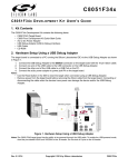
AN0821 S I MP L I C I T Y S T U D I O C8051F85 X W ALKTHROUGH 1. Introduction This document provides a step-by-step walkthrough that shows how to develop a basic embedded project using Simplicity Studio (IDE and Configurator) to run on the C8051F850 ToolStick Daughter Card (TOOLSTICK850-DC). The same steps can be applied to develop a project to run on the C8051F850 UDP MCU card (UPMU-F850 MCU). The project uses a potentiometer sampled via the ADC to control the brightness of an LED by controlling the duty cycle of an output pin using the PWM. Simplicity Configurator will be used to generate hardware initialization code for hardware peripherals, and Simplicity IDE will be used to develop, build, download, and debug the firmware project. Figure 1. Simplicity Studio—IDE and Configurator Walkthrough Rev. 0.1 2/14 Copyright © 2014 by Silicon Laboratories AN0821 AN0821 2. Relevant Documents IDE Guide—In Simplicity IDE, select HelpHelp Contents to display the Simplicity IDE Guide as well as any installed documentation, including data sheets and user’s guides. Simplicity Configurator Guide—In the Simplicity IDE, select HelpHelp Contents to display this guide. AN0822: Simplicity Studio User’s Guide—In addition to the documentation within the tool itself, this document provides a discussion of the Simplicity Studio tool. Application Notes are available on www.silabs.com/32bit-appnotes and www.silabs.com/8bit-appnotes. AN0823: Simplicity Configurator User’s Guide—In addition to the documentation within the tool itself, this document provides a discussion of the Simplicity Configurator tool. Application Notes are available on www.silabs.com/32bit-appnotes and www.silabs.com/8bit-appnotes. C8051F850 Data Sheet—http://www.silabs.com/products/mcu/smallmcu/pages/c8051f85x-86x.aspx (Documentation Tab) Simplicity 3. Installing Simplicity Studio 1. Download and install Simplicity Studio from www.silabs.com/8bit-software or www.silabs.com/simplicitystudio. 2. Run Simplicity Studio by selecting StartSilicon LabsSimplicity StudioSimplicity Studio from the start menu or double-clicking the Simplicity Studio shortcut on the desktop. 3. The Installation Setup wizard automatically runs after Simplicity Studio starts. To manually start the Installation Setup wizard, click the Add/Remove button on the top-right corner of the application. 4. Follow the instructions to install the software. The Full installation will include support both 8051 and EFM32 products. Choose the 8051 option for a reduced installation set. 5. The first time the project creation wizard runs, the Setup Environment wizard will guide the user through the process of configuring the build tools and SDK selection. 6. Simplicity Studio can detect if certain toolchains are not activated. If the Licensing Helper is displayed after completing the Setup Environment wizard, follow the instructions to activate the toolchain. Figure 2. Installing Simplicity Studio 2 Rev. 0.1 AN0821 4. Hardware Setup Setup the C8051F850 ToolStick hardware: Figure 3. Hardware Setup Diagram 1. Verify that the shorting block on JP1 is installed on the TOOLSTICK850-DC daughter card. 2. Connect the daughter card to the ToolStick Base Adapter. 3. Connect one end of the USB extension cable to the ToolStick Base Adapter and connect the other end to a PC. The USB connection provides power to the ToolStick Debug Adapter and daughter card. The ToolStick Debug Adapter can be used to write to the C8051F850 flash and to enable on-chip debug support. 5. Software Setup Install Simplicity Studio as described in "3. Installing Simplicity Studio" on page 2, select a Typical or 8051 installation. Select the C8051F85x/86x devices in the Part Selection window. 6. Using Configurator to Pulse Width Modulate (PWM) an LED The PWM LED project uses a potentiometer sampled by the ADC to control the brightness of an LED by controlling the duty cycle of an output pin using the Programmable Counter Array (PCA) to generate a PWM waveform. After configuring the Simplicity IDE, the next step is to create a new project using the New Silicon Labs MCU Project wizard. Each project has its own source files, target configuration, SDK configuration, and build configurations such as the Debug and Release build configurations. The IDE can be used to manage multiple projects in a collection called a workspace. Workspace settings are applied globally to all projects within the workspace. This can include settings such as key bindings, window preferences, and code style and formatting options. Project actions, such as build and debug are context sensitive. For example, the user must select a project in the Project Explorer view in order to build that project. Rev. 0.1 3 AN0821 Create a new Silicon Labs MCU Project called F85x_PWM_LED: 1. Create a new project by selecting FileNewSilicon Labs MCU Project from the menu bar. 2. Complete the New Silicon Labs MCU Project wizard: a. In the Project setup step, select C8051F850 Development Kit from the Kit combo box. This will automatically select the C8051F850 part in the Part combo box. b. Select Si8051 SDK (v2.0.0) from the SDK combo box. c. Click the Next button. d. Select the Simplicity Configurator Program radio button from the Project Type list. Simplicity Studio Configurator generates hardware initialization code using a graphical interface. e. Click the Next button. f. In the Project Configuration step, enter F85x_PWM_LED in the Project Name text box. g. Select the C8051F850-C-GU-QSOP device from the Device list box. h. Click the Finish button. 2a 2e 2d 2c 2b 2f 2g 2h Simplicity Studio Configurator greatly simplifies MCU peripheral initialization by presenting peripherals and peripheral properties in a graphical user interface. The majority of the initialization firmware can be generated by selecting peripherals and selecting property values from combo boxes or entering register values in text boxes. 4 Rev. 0.1 AN0821 Some peripherals provide calculators such as baud rate calculators, timer overflow rate calculators, and SPI clock rate calculators that can be used to automatically calculate the necessary reload register value to generate the clock rate specified by the user. Configurator also provides real-time validation of properties to ensure that a configuration is valid before downloading code to the MCU. The following steps will detail the configuration of the C8051F850 peripherals to generate a PWM output based on the measured ADC input. In summary: Timers Watchdog Timer Enable—Disable TIMER 2 (16-bit Timer with Auto Reload, Overflow at 1 kHz) Run Control—Start Timer Overflow Frequency—1000 PCA 0 (8-bit PWM, Frequency = 1 kHz) Channel 0 Capture/Compare Mode—Predefined 8~11-bit pulse modulator PCA Counter/Timer Run Control—Start WDT Analog ADC 0 (8-bit Mode, 1x gain, Sample P1.2 on Timer 2 overflow) 8-bit Mode—8-bit Mode Gain Control—1x gain Resolution—8-bit Enable ADC—Enabled Start of Conversion—Timer 2 overflow Positive Input Selection—ADC0.10 (P1.2) Voltage Reference Select Voltage Reference—VDD pin Enable Core Interrupts Enable Enable Port ADC0 Conversion Complete Interrupt—Enabled All Interrupts—Enabled I/O Peripheral Mapping PCA0_CEX0—Checked Enable Crossbar—Enabled - P0.7 Skip—Skipped P1.0 IOMode—Digital Push-Pull Output P1.2 IOMode—Analog I/O Skip—Skipped P0.0 Rev. 0.1 5 AN0821 1. After creating a new MCU project using Simplicity Configurator, Studio will automatically switch to the Configuration perspective. This perspective is tailored specifically for use with Configurator to initialize MCU peripherals. Special views will automatically be displayed in this perspective that allow peripheral registers to be configured. The default tab in a new Configurator project is the Port I/O tab. 2. Studio will automatically validate register configuration values and display any errors or warnings in the Problems view. Disable the watchdog timer to fix the warning: a. Double clicking on a warning or error will automatically display the property that raised the problem. Double click on the Watchdog timer warning to automatically switch to the Peripherals editor and display the Watchdog Timer properties in the Properties view. b. The Peripherals tab shows all of the hardware peripherals that Configurator can generate initialization code for. Peripherals are grouped by categories such as Analog, Communications, Core, and Timers. c. Check the check box next to a peripheral to indicate that Configurator should generate code for the checked peripheral module. Selecting a peripheral will display the peripheral properties for the selected peripheral in the Properties view. d. Disable the watchdog timer to prevent unwanted device resets from occurring. Select the WDT Enable property in the Properties view and select Disable from the combo box. Press enter or deselect the property to confirm the new property value. e. The watchdog timer warning in the Problems view should now disappear, indicating that the problem has been solved. 2 2c 2d 2a 2b 6 Rev. 0.1 AN0821 3. Confirm that the MCU system clock is configured as SYSCLK / 8 or 3.0625 MHz: a. Select the Peripherals tab, if it’s not already selected. b. Select the Clock Control box from the Clocking group to display the properties in the Properties view. c. Verify that the Clock Source Divider property is set to SYSCLK / 8 and SYSCLK is set to 3062500. 3b 3c 3a Rev. 0.1 7 AN0821 4. Next, configure Timer 2 to overflow at 1 kHz. This timer will serve as the ADC start-of-conversion source. a. Select TIMER 2 from the Timers group. b. Set the Run Control property to Start. c. Set the Timer Overflow Frequency properties to 1000 for 1 kHz. This will change the read-only Timer Reload Overflow Frequency to ~1 kHz. d. Check the TIMER Setup check box to enable code generation and remove the error. e. Timer 2 is now clocked from the 3.0625 MHz system clock divided by 12 and the 16-bit Timer 2 counter will overflow approximately every 1 ms (1 kHz). 4a 4d 4b 4c 8 Rev. 0.1 AN0821 5. Configure PCA 0 to output an 8-bit PWM signal on P1.0 at 1 kHz: a. Select PCA 0 from the Timers group. b. Set the Channel 0 Capture/Compare Mode property to Predefined 8~11-bit pulse modulator. c. Set the PCA Counter/Timer Run Control property to Start. 5b 5a 5c Rev. 0.1 9 AN0821 6. Next, configure ADC 0 to acquire 8-bit samples on P1.2, the potentiometer pin, on Timer 2 overflow: a. Select ADC 0 from the Analog group. b. Set the Enable ADC property to Enabled. c. Set the Start of Conversion property to Timer 2 overflow. d. Set the Positive Input Selection property to ADC0.10 (P1.2). e. Set the Resolution property to 8-bit. f. Set the Enable 8-bit Mode property to 8-bit mode. g. Set the Gain Control property to 1x gain. 6a 6b 6c 6d 6e 6f 10 Rev. 0.1 6g AN0821 7. Configure the voltage reference for the ADC to use VDD: a. Select Voltage Reference from the Analog group. b. Set the Select Voltage Reference property to VDD pin. 7a 7b Rev. 0.1 11 AN0821 8. Enable ADC 0 conversion complete interrupts and enable the global interrupt enable flag: a. Select Interrupts from the Core group. b. Set the Enable ADC0 Conversion Complete Interrupt property to Enabled. c. Set the Enable All Interrupts property to Enabled. 8a 8b 8c 12 Rev. 0.1 AN0821 9. Enable the PCA0_CEX0 pin on the crossbar: a. Switch to the Port I/O tab. b. Click CROSSBAR0 from the Outline view. c. Switch to the Peripheral Mapping view, if it’s not already open. d. Check only the PCA0_CEX0 check box. 9b 9c 9a 9d Rev. 0.1 13 AN0821 10. Place PCA0_CEX0 on the P1.0 LED pin by skipping P0.0 through P0.7 on the crossbar: a. Click P0.2 in the Port I/O editor. b. Holding the Ctrl key, click each pin from P0.0 through P0.7 to select all 8 pins. c. Set the Skip property to Skipped or right-click on the pins and select Skip Selected Pins. 10a 10b 10c 14 Rev. 0.1 AN0821 11. Configure PCA_CEX0 / P1.0 (LED) for push-pull output mode: a. Select PCA0_CEX0 / P1.0 or pin 18. b. Set the IOMode property to Digital Push-Pull Output. 11a 11b Rev. 0.1 15 AN0821 12. Configure ADC0.10 / P1.2 (Potentiometer) for analog mode and skipped on the crossbar: a. Select ADC_IN / P1.2 or pin 16. b. Set the IOMode property to Analog I/O. c. Set the Skip property to Skipped. 12a 12b 12c 16 Rev. 0.1 AN0821 13. Enable the crossbar to enable the port pin drivers and weak pullup resistors: a. Select Port I/O from the Outline view to display the Port Config properties. b. Set the Enable Crossbar property to Enabled. 13a 13b Rev. 0.1 17 AN0821 14. After configuring peripheral properties, save the F85x_PWM_LED.hwconf file to generate InitDevice.c, InitDevice.h, and Interrupts.c: a. Select the F85x_PWM_LED.hwconf editor tab. b. Click the Save button from the tool bar. The save file operation is context sensitive and will only save the currently active document in the editor. c. Configurator generates InitDevice.c, which contains source code to initialize the peripherals as configured in the GUI. d. Configurator also generates InitDevice.h, which contains function prototypes for initialization routines. e. Finally, Configurator generates Interrupts.c, which contains the interrupt service routines. 14b 14c 14a 14e 14d 18 Rev. 0.1 AN0821 After generating hardware initialization functions using Simplicity Configurator, edit the source code to copy the ADC reading into the PCA PWM output. The Eclipse framework provides a very powerful editor with rich features, such as C++ syntax error highlighting, code completion, and source browse information to quickly locate symbol declarations. Edit the F85x_PWM_LED project source code to change the PWM duty cycle based on the ADC sample to change the LED brightness: 1. Double-click on the Interrupts.c file in the Project Explorer. 1 Rev. 0.1 19 AN0821 2. Enter the following code into the ADC ISR and save the document: ADC0CN0_ADINT = 0; PCA0CPH0 = (U8)(ADC0 >> 2); 2 20 Rev. 0.1 AN0821 3. Build the project and make sure that there are no errors or warnings: a. Select the F85x_PWM_LED project in the Project Explorer. b. Select ProjectBuild Project from the menu bar or use the Build button on the tool bar. The Project menu is context sensitive, which means that an active project must be selected before building the project. c. The compiler and linker build output will be displayed in the Console view. d. Check the Problems tab to see if there are any errors or warnings. e. Correct any problems before continuing. 3b 3a 3d 3c Rev. 0.1 21 AN0821 4. Simplicity IDE supports many modern code editing features. For example, the IDE will automatically index all code within the project to support symbol lookup. The code does not have to build completely for the indexer to work. However certain features may not be available if for example, the main() routine is not declared. Next, use the Open Declaration feature to quickly find symbol declarations: a. If not already open, open the Interrupts.c document by double clicking Interrupts.c in the Project Explorer. b. Right click on ADC0CN0_ADINT to display the context menu. c. Click Open Declaration to quickly navigate to the definition of ADC0CN0_ADINT. d. Studio will automatically open SI_C8051F850_Defs.h and highlight the line containing the declaration of ADC0CN0_ADINT. 4a 4b 4c 4d 22 Rev. 0.1 AN0821 5. Simplicity IDE also supports code completion, a feature called Content Assist. The user can type the first few letters of a symbol or include file and press Ctrl+Space to display a list of symbols that match the letters types. Next, use Content Assist to display a list of symbols starting with the characters P1: a. In Interrupts.c, type ADC0 at the end of the ADC0_ISR function. b. Press Ctrl+Space to display the Content Assist list. c. Use the arrow keys or page up and down keys to look through the list of matching symbols. d. Pressing Enter will replace the typed characters with the selected symbol. e. Once familiar with the Content Assist feature, delete any lines inserted in this step. 5a 5b Rev. 0.1 23 AN0821 Once an MCU project builds, start a debug session. If a single USB Debug Adapter or ToolStick Debug Adapter is available, the IDE will automatically download the code to the MCU. If more than one debug adapter is available, the IDE will prompt the user to select a debugger. The Silicon Labs 8051 products support non-intrusive, on-chip debug that provides hardware breakpoints, single stepping, and register/memory view. 1. Start a new debug session: a. Select F85x_PWM_LED from the Project Explorer. b. Click the Debug button. The IDE will automatically switch to the Debug perspective. This perspective can be used to set breakpoints, run/halt the CPU, single step, view/modify register values, and display the disassembly viewer. c. The Debug view in the top-left corner displays any active debug sessions. A debug adapter can only support a single debug session at a time. An active debug session must be disconnected before code can be recompiled and a new debug session started. 1b 1a 1c 2. Press the Resume button in the IDE. This will start the code running, and rotating the potentiometer will brighten and dim the P1.0 LED. 24 Rev. 0.1 AN0821 3. Use a breakpoint to halt the CPU just prior to executing the statement to read the ADC sample and update the PWM duty cycle: a. Open Interrupts.c in the editor. If Interrupts.c is not shown in the tabbed list of files, then quickly switch to the Development perspective and use the Project Explorer to open the Interrupts.c file. Next, switch back to the Debug perspective. The debug session is still active when switching perspectives. Files shown in the editor will be visible in both the Development and Debug perspectives. b. Scroll down to the following line in Interrupts.c: PCA0CPH0 = (U8)(ADC0 >> 2); c. Move the mouse cursor to the left-hand margin of the editor in the highlighted blue region. Double-click the margin to add or remove a breakpoint at the corresponding source code line. d. The core will halt on the breakpoint. Clicking the Resume button will run the CPU until the ADC conversion complete interrupt fires again. Then the CPU will halt and all of the debug windows will update to reflect the new CPU state. 3d 3a 3b 3c Rev. 0.1 25 AN0821 4. Use the Registers view to view/modify register values: a. Select the Registers tab. b. Scroll down the register list and expand the ADC registers. c. The ADC0 sample value is displayed in the ADC0 row under the Value column. d. The register description is displayed in the Description column. e. Registers with bitfields will be split into individual fields with the enumeration value decoded. f. Registers that have changed between breakpoints will be highlighted in yellow. 4a 4f 4b 4c 4e 26 Rev. 0.1 4d AN0821 5. Use the Expressions view to display the current value of code expressions: a. Select the Expressions tab. b. Highlight the expression, ADC0, in main.c. c. Drag the highlighted expression to the line just below the Add new expression button in the Expressions view. d. If possible, Studio will evaluate the expression and display its current value when the MCU is halted. If an expression is out of scope, Studio will not be able to evaluate the expression until the MCU is halted in a section of code where the expression is in scope. 5a 5c 5b Rev. 0.1 27 AN0821 6. Use the Memory view to display the contents of the CODE, RAM, and XRAM memory: a. Select the Memory tab in the bottom-left hand. b. Click the Add Memory Monitor button. The Monitor Memory dialog will appear. c. Select the Enter memory space and address radio button. d. Select the CODE memory space from the combo box. e. Enter an address to view, such as 0x0000. Press OK. f. Notice that a new memory monitor has been added to the Memory view that displays the contents of CODE space starting at 0x0000. 6c 6e 6a 6d 6b 28 6f Rev. 0.1 AN0821 CONTACT INFORMATION Silicon Laboratories Inc. 400 West Cesar Chavez Austin, TX 78701 Tel: 1+(512) 416-8500 Fax: 1+(512) 416-9669 Toll Free: 1+(877) 444-3032 Please visit the Silicon Labs Technical Support web page: https://www.silabs.com/support/pages/contacttechnicalsupport.aspx and register to submit a technical support request. Patent Notice Silicon Labs invests in research and development to help our customers differentiate in the market with innovative low-power, small size, analogintensive mixed-signal solutions. Silicon Labs' extensive patent portfolio is a testament to our unique approach and world-class engineering team. The information in this document is believed to be accurate in all respects at the time of publication but is subject to change without notice. Silicon Laboratories assumes no responsibility for errors and omissions, and disclaims responsibility for any consequences resulting from the use of information included herein. Additionally, Silicon Laboratories assumes no responsibility for the functioning of undescribed features or parameters. Silicon Laboratories reserves the right to make changes without further notice. Silicon Laboratories makes no warranty, representation or guarantee regarding the suitability of its products for any particular purpose, nor does Silicon Laboratories assume any liability arising out of the application or use of any product or circuit, and specifically disclaims any and all liability, including without limitation consequential or incidental damages. Silicon Laboratories products are not designed, intended, or authorized for use in applications intended to support or sustain life, or for any other application in which the failure of the Silicon Laboratories product could create a situation where personal injury or death may occur. Should Buyer purchase or use Silicon Laboratories products for any such unintended or unauthorized application, Buyer shall indemnify and hold Silicon Laboratories harmless against all claims and damages. Silicon Laboratories and Silicon Labs are trademarks of Silicon Laboratories Inc. Other products or brandnames mentioned herein are trademarks or registered trademarks of their respective holders. Rev. 0.1 29