1
AN0009: Getting Started with EFM32,
EZR32, and EFM32 Gemstones
This application note introduces the software examples, libraries,
documentation, and software tools available for EFM32, EZR32,
and EFM32 Gemstones.
In addition to providing a basic introduction to the tools available for these devices, this
document includes several basic firmware exercises to familiarize the reader with the
Starter Kit and Development Kit hardware, the emlib firmware library, and the Simplicity
Studio software tools.
Note that this document focuses on the MCU portion of the devices. For wireless products (EZR32), see the additional wireless getting started information available in the
user guide specifically for the product. More information on the hardware for any product can be found in the kit user guide. More information about Simplicity Studio in general can be found in AN0822: "Simplicity Studio™ User Guide". Application notes can
be found on the Silicon Labs website (www.silabs.com/32bit-appnotes) or using the
[Application Notes] tile in Simplicity Studio.
silabs.com | Smart. Connected. Energy-friendly.
KEY POINTS
• Simplicity Studio contains everything
needed to develop with EFM32, EZR32,
and EFM32 Gemstones.
• Things you will learn:
• Basic register operation
• Using emlib functions
• Blinking LEDs and reading buttons
• LCD controller
• Energy Modes
• Real-Time Counter operation
Rev. 1.19
AN0009: Getting Started with EFM32, EZR32, and EFM32 Gemstones
Introduction
1. Introduction
1.1 Prerequisites
The examples in this application note require access to a supported Silicon Labs device. Supported devices include the EFM32,
EZR32, and EFM32 Gemstones kit (either Starter or Development). Before working on this tutorial, ensure a compatible IDE is available by either:
• installing Simplicity Studio from Silabs.com (http://www.silabs.com/simplicity), or
• if IAR is preferred, install the latest Segger J-Link drivers to support the kit (https://www.segger.com/jlink-software.html)
In Simplicity Studio, ensure that all the available packages are installed and up to date by clicking on the [Update Software] button at
the top-right of the main window:
Note: While Simplicity Studio includes a fully-functional integrated IDE, it also supports some third party IDEs, including IAR. For this
reason, it is recommended to install Simplicity Studio regardless of the preferred IDE for easy access to these examples as well as the
full suite of features provided to facilitate development of EFM32, EZR32, and EFM32 Gemstones solutions.
1.2 How to Use this Application Note
The source code for this application note is placed in individual folders named after the kit for which each example is intended.
The easiest way to access the example source code and projects is through the [Application Notes] tile in Simplicity Studio. Simply
click this tile to open the [Application Notes] dialog:
Click to open Application Notes
Figure 1.1. Application Notes Tile in Simplicity Studio
Within the [Application Notes] dialog, navigate to and select the [AN0009 Getting Started with EFM32] entry, then click the [Import
Project...] button to view the list of available example projects. Use the project names to identify examples compatible with the kit and
select one to import that project into the IDE (by default, this is the Simplicity Studio IDE, but this configuration can be changed to an
alternative IDE, if desired).
Alternatively, projects for multiple IDEs are stored in separate folders (iar, arm, etc.) in the filesystem that hosts these examples, accessible with the [Open Folder] button in the Simplicity Studio Applications Notes dialog. These projects can be manually loaded in the
appropriate IDE. All of the IAR projects are also collected in one common workspace called efm32.eww. Since the projects are slightly
different for the various kits, make sure to open the project that is prefixed with the name of the kit in use.
Note: The code examples in this application note are not complete, and the reader is required to fill in small pieces of code throughout
the exercises. A completed code file (postfixed with *_solution.c) also exists for each example.
silabs.com | Smart. Connected. Energy-friendly.
Rev. 1.19 | 1
AN0009: Getting Started with EFM32, EZR32, and EFM32 Gemstones
Register Operation
2. Register Operation
This chapter explains the basics of how to write C-code for the EFM32 devices using the defines and library functions supplied in the
[CMSIS] and [emlib] software libraries.
2.1 Address
The EFM32, EZR32, and EFM32 Gemstones devices consist of several different types of peripherals (CMU, RTC, ADC...). Some peripherals in the device exist only as one instance, like the Clock Management Unit (CMU). Other peripherals like Timers (TIMERn) exist
as several instances and the name is postfixed by a number (n) denoting the instance number. Usually, two instances of a peripheral
are identical, but are placed in different regions of the memory map. However, some peripherals have a different feature set for each of
the instances. For example, USART0 can have an IrDA interface, while USART1 cannot. Such differences will be explained in the device data sheet and the reference manual.
Each peripheral instance has a dedicated address region which contains registers that can be accessed by read/write operations. The
peripheral instances and memory regions are found in the device data sheet. The starting address of a peripheral instance is called the
base address. The reference manual for the device series contains a complete description of the registers within each peripheral. The
address for each register is given as an offset from the base address for the peripheral instance.
silabs.com | Smart. Connected. Energy-friendly.
Rev. 1.19 | 2
AN0009: Getting Started with EFM32, EZR32, and EFM32 Gemstones
Register Operation
2.2 Register Description
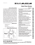
The EFM32, EZR32, and EFM32 Gemstones devices use a 32-bit bus for write/read access to the peripherals, and each register in a
peripheral contains 32 bits, numbered 0-31. Unused bits are marked as reserved and should not be modified. The bits used by the
peripheral can either be single bits (e.g. OUTEN bit in the figure below) or grouped together in bitfields (e.g. PRSSEL bitfield in the
figure below). Each bitfield is described with the following attributes:
• Bit position
• Name
• Reset value
• Access type
• Description
Figure 2.1. Example Register Description
silabs.com | Smart. Connected. Energy-friendly.
Rev. 1.19 | 3
AN0009: Getting Started with EFM32, EZR32, and EFM32 Gemstones
Register Operation
2.3 Access Types
Each register has a set access type for all of the bit fields within that register. The access types describes the reaction to read or write
operation to the bit field. The different access types found for the registers in the devices are described in the table below.
Table 2.1. Register Access Types
Access Type
R
Description
Read only. Writes are ignored
RW
Readable and writable
RW1
Readable and writable. Only writes to 1 have effect
W1
Read value undefined. Only writes to 1 have effect
W
Write only. Read value undefined.
RWH
Readable, writable, and updated by hardware
2.4 CMSIS and emlib
The Cortex Microcontroller Software Interface Standard (CMSIS) is a common coding standard for all ARM Cortex devices. The CMSIS
library provided by Silicon Labs contains header files, defines (for peripherals, registers and bitfields), and startup files for all devices. In
addition, CMSIS also includes functions that are common to all Cortex devices, like interrupt handling, intrinsic functions, etc. Although
it is possible to write to registers using hard coded address and data values, it is recommended to use the defines to ensure portability
and readability of the code.
In order to use these defines, projects must include em_device.h in the c-file. This is a common header file for all EFM32, EZR32, and
EFM32 Gemstones devices. Within this file, the header file content for the appropriate device is included in the project builds according
to the preprocessor symbols defined for the project.
To simplify the programming of EFM32, EZR32, and EFM32 Gemstones devices, Silicon Labs developed and maintains a complete Cfunction library called [emlib] that provides efficient, clear, and robust access to and control of all peripherals and core functions in the
device. This library resides within the em_xxx.c (e.g. em_dac.c) and em_xxx.h files in the emlib folder.
In the source files included with this application note, the em_chip.h is included in each and a call to CHIP_Init() exists near the
beginning of every main() function. Like the content of em_device.h, the actions taken within the CHIP_Init() function depends on
the specific part in use, but will include correcting for known errata and otherwise ensuring consistent behavior across devices. For this
reason, do not run any code in the main function prior to running the CHIP_Init() function.
2.4.1 CMSIS Documentation
Complete Doxygen documentation for the EFM32, EZR32, and EFM32 Gemstones [CMSIS] library and [emlib] is available via the
[Software Documentation] tile in the [Software and Kits] grouping of Simplicity Studio main page. This documentation is also available on the Silicon Labs website at http://devtools.silabs.com/dl/documentation/doxygen/.
silabs.com | Smart. Connected. Energy-friendly.
Rev. 1.19 | 4
AN0009: Getting Started with EFM32, EZR32, and EFM32 Gemstones
Register Operation
2.4.2 Peripheral Structs
In the emlib header files, the register defines for each peripheral type are grouped in structs as defined in the example below:
typedef struct
{
__IO uint32_t CTRL;
__I uint32_t STATUS;
__IO uint32_t CH0CTRL;
__IO uint32_t CH1CTRL;
__IO uint32_t IEN;
__I uint32_t IF;
__O uint32_t IFS;
__O uint32_t IFC;
__IO uint32_t CH0DATA;
__IO uint32_t CH1DATA;
__O uint32_t COMBDATA;
__IO uint32_t CAL;
__IO uint32_t BIASPROG;
} DAC_TypeDef;
Recall that a register address consists of a base address for the peripheral instance plus an additional offset. The peripheral structs in
[emlib] simplify writing to a register and abstract away these underlying addresses and offsets. Hence, writing to CH0DATA, in the
DAC0 peripheral instance can then be done like this:
DAC0->CH0DATA = 100;
Similarly, reading a register can be done like this:
myVariable = DAC0->STATUS;
2.4.3 Bit Field Defines
Every device has relevant bit fields defined for each peripheral. These definitions are found within the efm32xx_xxx.h (e.g. efm32tg_da
c.h) files and are automatically included with the appropriate [emlib] peripheral header file.
#define
#define
#define
#define
#define
#define
#define
#define
#define
#define
#define
#define
_DAC_CTRL_REFRSEL_SHIFT
_DAC_CTRL_REFRSEL_MASK
_DAC_CTRL_REFRSEL_DEFAULT
_DAC_CTRL_REFRSEL_8CYCLES
_DAC_CTRL_REFRSEL_16CYCLES
_DAC_CTRL_REFRSEL_32CYCLES
_DAC_CTRL_REFRSEL_64CYCLES
DAC_CTRL_REFRSEL_DEFAULT
DAC_CTRL_REFRSEL_8CYCLES
DAC_CTRL_REFRSEL_16CYCLES
DAC_CTRL_REFRSEL_32CYCLES
DAC_CTRL_REFRSEL_64CYCLES
20
0x300000UL
0x00000000UL
0x00000000UL
0x00000001UL
0x00000002UL
0x00000003UL
(_DAC_CTRL_REFRSEL_DEFAULT << 20)
(_DAC_CTRL_REFRSEL_8CYCLES << 20)
(_DAC_CTRL_REFRSEL_16CYCLES << 20)
(_DAC_CTRL_REFRSEL_32CYCLES << 20)
(_DAC_CTRL_REFRSEL_64CYCLES << 20)
For every register bitfield, associated shift, mask and default value bit fields are also defined.
#define
#define
#define
#define
#define
DAC_CTRL_DIFF
_DAC_CTRL_DIFF_SHIFT
_DAC_CTRL_DIFF_MASK
_DAC_CTRL_DIFF_DEFAULT
DAC_CTRL_DIFF_DEFAULT
silabs.com | Smart. Connected. Energy-friendly.
(0x1UL << 0)
0
0x1UL
0x00000000UL
(_DAC_CTRL_DIFF_DEFAULT << 0)
Rev. 1.19 | 5
AN0009: Getting Started with EFM32, EZR32, and EFM32 Gemstones
Register Operation
2.4.4 Register Access Examples
When setting a bit in a control register, it is important to make sure firmware does not unintentionally clear other bits in the register. To
ensure this, the mask with the bit firmware needs to set can be OR'ed with the original contents, as shown in the example below:
DAC0->CTRL = DAC0->CTRL | DAC_CTRL_LPFEN;
A more compact version is:
DAC0->CTRL |= DAC_CTRL_LPFEN;
Clearing a bit is done by ANDing the register with a value with all bits set except for the bit to be cleared:
DAC0->CTRL = DAC0->CTRL & ~DAC_CTRL_LPFEN; // or
DAC0->CTRL &= ~DAC_CTRL_LPFEN;
When setting a new value to a bit field containing multiple bits, a simple OR function will not do, since this will risk that the original bit
field contents OR'ed with the mask will give a wrong result. Instead, make sure to clear the entire bit field (and only the bit field) before
ORing in the new value:
DAC0->CTRL = (DAC0->CTRL & ~_DAC_CTRL_REFRSEL_MASK) | DAC_CTRL_REFRSEL_16CYCLES;
2.4.5 Grouped Registers
Some registers are grouped together within each peripheral. An example of such a group is the registers associated with each GPIO
port, like the Data Out Register (DOUT) in the figure below. Each GPIO port (A, B, C, ...) contains a DOUT register and the description
below is common for all of these. The x in GPIO_Px_DOUT indicates the port wild card.
Figure 2.2. Grouped Registers in GPIO
In the CMSIS defines the port registers are grouped in an array P[x]. When using this array, we must index it using numbers instead of
the port letters (A=0, B=1, C=2, ...). Accessing the DOUT register for port C can be done like this:
GPIO->P[2].DOUT = 0x000F;
silabs.com | Smart. Connected. Energy-friendly.
Rev. 1.19 | 6
AN0009: Getting Started with EFM32, EZR32, and EFM32 Gemstones
Example 1 — Register Operation
3. Example 1 — Register Operation
This example will show how to write and read registers using the CMSIS defines. This tutorial also shows how to observe and manipulate register contents through the debugger in Simplicity Studio or IAR Embedded Workbench. While the examples are shown only for
Simplicity Studio and IAR, the tasks can also be completed in other supported IDEs.
For Simplicity Studio:
1. Connect the kit to the PC.
2. Open Simplicity Studio and click the [Refresh detected hardware] button on the left. Once the kit appears, click on the kit.
3. Click the [Application Notes] tile.
4. Search for [AN0009] and click the document in the list, then click the [Import Project...] button.
5. Select the [<kit_name>_1_registers.slsproj] option in the dialog and click [OK].
6. Double-click on the 1_registers.c file to open it in the editor view. There's a marker where custom code should be added.
For IAR:
1. Open up the efm32 workspace (an\an0009_efm32_getting_started\iar\efm32.eww).
2. Select the [<kit_name>_1_register] project in IAR EW.
3. In the main function in the 1_registers.c (inside Source Files), there's a marker where custom code should be added.
3.1 Step 1 — Enable Timer Clock
In this example, we are going to use TIMER0. By default the 14 MHz RC oscillator is running, but all peripheral clocks are disabled, so
we must turn on the clock for TIMER0 before we use it. If we look in the CMU chapter of the reference manual, we see that the clock to
TIMER0 can be switched on by setting the TIMER0 bit in the HFPERCLKEN0 register in the CMU peripheral.
3.2 Step 2 — Start Timer
Starting the Timer is done by writing a 1 to the START bit in the CMD register in TIMER0.
3.3 Step 3 — Wait for Threshold
Create a while-loop that waits until the counter is 1000 before proceeding.
silabs.com | Smart. Connected. Energy-friendly.
Rev. 1.19 | 7
AN0009: Getting Started with EFM32, EZR32, and EFM32 Gemstones
Example 1 — Register Operation
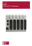
3.4 Observation
For Simplicity Studio, make sure the [<kit_name>_1_register] project is active by clicking the project in the left-hand [Project] view.
Then, press the [Debug] button to automatically build and download the code to the device. Click the [Registers] view and find the
STATUS register in TIMER0. After expanding the register, notice that the RUNNING bit set to 0.
In the code view, double-click the left pane to place a breakpoint before firmware starts the timer and click the [Resume] button. Then,
watch the RUNNING bit get set to 1 in the [Registers] view when single stepping over the expression using the [Step Over] button.
Continue to single step and note that the content of the CNT registers is increasing. Try writing a different value to the CNT register by
entering it directly in the [Registers] view.
Build and Debug
Disconnect
Resume
Step Over
Registers View
Expressions View
Reset
Double-click to
add a breakpoint
Figure 3.1. Debug View in Simplicity Studio
For IAR, make sure the <kit_name>_1_register project is active by pressing the corresponding tab at the bottom of the Workspace window. Then, press the Download & Debug button and go to View->Register and find the STATUS register in TIMER0. After expanding
the register, notice that the RUNNING bit is set to 0.
Place the cursor in front of the line where firmware starts the timer and press [Run to Cursor]. Then, watch the RUNNING bit get set to
1 in the Register View when clicking the [Single Step] button to move over the expression. Continue to click the [Single Step] button to
see the content of the CNT registers increasing. Try writing a different value to the CNT register by entering it directly in the Register
View.
silabs.com | Smart. Connected. Energy-friendly.
Rev. 1.19 | 8
AN0009: Getting Started with EFM32, EZR32, and EFM32 Gemstones
Example 1 — Register Operation
Reset
Step Into
Run to cursor
Exit debug
Download and Debug
Run
Figure 3.2. Debug View in IAR
silabs.com | Smart. Connected. Energy-friendly.
Rev. 1.19 | 9
AN0009: Getting Started with EFM32, EZR32, and EFM32 Gemstones
Example 2a — Blinking LEDs with an STK
4. Example 2a — Blinking LEDs with an STK
Since accessing the LEDs is done differently for the Development Kits and the Starter Kits, this example is split into two parts: 2a (for
STK), and 2b (for DK). In this example for the STKs, the aim is to use the GPIO pins to light up the LEDs on the STK and change the
LED configuration every time a button is pressed. Instead of accessing the registers directly, use the emlib functions to configure the
peripherals.
The starting The AN0009 application note includes a [<kit_name>_2_leds] example in Simplicity Studio, and the IAR efm32 workspace
contains a project called <kit_name>_2_leds, which will be used in this example. The emlib C-files are included in the project. The corresponding header files are included at the beginning of the C-files.
For details on which emlib functions exist and how to use them, open the API documentation through through Simplicity Studio using
the [Software Documentation] tile (or by going to http://devtools.silabs.com/dl/documentation/doxygen/). After clicking on the emlib
link for the correct device series (Gecko, Tiny Gecko etc.), open up [Modules->EM_Library] and select the CMU peripheral. Find a list
of functions for this peripheral by scrolling down to the [Functions] section. These functions can be used to to easily operate the Clock
Management Unit.
Figure 4.1. Documentation for the CMU-specific emlib Functions
silabs.com | Smart. Connected. Energy-friendly.
Rev. 1.19 | 10
AN0009: Getting Started with EFM32, EZR32, and EFM32 Gemstones
Example 2a — Blinking LEDs with an STK
4.1 Step 1 — Turn on GPIO clock
In the list of CMU functions we find the following function to turn on the clock to the GPIO:
void CMU_ClockEnable(CMU_Clock_TypeDef clock, bool enable)
If we click on the function, we are shown a description of how to use the function. Clicking on the [CMU_Clock_TypeDef] link goes to a
list of the allowed enumerators for the clock argument. To turn on the GPIO, add the following:
CMU_ClockEnable(cmuClock_GPIO, true);
Figure 4.2. CMU_ClockEnable Function Description
4.2 Step 2 — Configure GPIO Pins for LEDs
The User Manual for a kit is available in Simplicity Studio using the [Kit Documentation] tile. This document describes the usage of all
the pins, including the user LED(s). These LED(s) are connected as follows on several example kits:
•
•
•
•
EFM32-Gxxx-STK: 4 LEDs on port C, pins 0-3
EFM32TG-STK3300: 1 LED on port D, pin 7
EFM32GG-STK3700: 2 LEDs on port E, pins 2-3
EFM32ZG-STK3200: 2 LEDs on port C, pins 10-11
Consult the user guide for information specific to the kit in use.
Looking into the available functions for the GPIO, the following function can be used to configure the mode of the GPIO pins:
void GPIO_PinModeSet(GPIO_Port_TypeDef port, unsigned int pin,
GPIO_Mode_TypeDef mode, unsigned int out)
Use this function to configure the LED pin(s) as Push-Pull outputs with the initial DOUT value set to 0.
silabs.com | Smart. Connected. Energy-friendly.
Rev. 1.19 | 11
AN0009: Getting Started with EFM32, EZR32, and EFM32 Gemstones
Example 2a — Blinking LEDs with an STK
4.3 Step 3 — Configure a GPIO Pin for a Button
Look at the User Manual for the STK to find where Push Button 0 (PB0) is connected on the kit in use. This button is connected on
several example kits as follows:
•
•
•
•
EFM32-Gxxx-STK: Port B, pin 9
EFM32TG-STK3300: Port D, pin 8
EFM32GG-STK3700: Port B, pin 9
EFM32ZG-STK3200: Port C, pin 8
Configure this pin as an input to be able to detect the button state.
4.4 Step 4 — Change LED Status when a Button is Pressed
Write a loop that toggles the LED(s) every time PB0 is pressed. Make sure to not only check that the button is pressed, but also that it
is released, so that the LED(s) only toggle once for each button press. PB0 is pulled high by an external resistor.
4.5 Extra Task — LED Animation
Experiment with creating different blinking patterns on the LED(s), like fading and running LEDs (if there are multiple LEDs). Because
the device typically runs in the 14 MHz range by default, add a delay function to be able to see the LEDs changing in real-time. Using
the code for TIMER0 in Example 1, create the following function:
void Delay(uint16_t milliseconds)
Use the PRESC bitfield in TIMER0_CTRL to reduce the clock frequency to a desired value.
silabs.com | Smart. Connected. Energy-friendly.
Rev. 1.19 | 12
AN0009: Getting Started with EFM32, EZR32, and EFM32 Gemstones
Example 2b — Blinking LEDs with a DK
5. Example 2b — Blinking LEDs with a DK
Use a Development Kit to run this example. The aim is to use the GPIO pins to light up the LEDs on the DK and change the LED
configuration every time the joystick is moved. The AN0009 application note includes a [<kit_name>_2_leds] example in Simplicity
Studio, and the IAR efm32 workspace contains a project called <kit_name>_2_leds, which will be used in this example.
5.1 Board Support Library
The Development Kits use a board controller to configure the functions of the development kit, including lighting the user leds and reading buttons/joystick. These functions can be controlled by the MCU device by communicating with the board controller via either SPI or
External Bus Interface. The device can then configure the registers in the board controller to set up the functions wanted. The Board
Support Library includes drivers for handling access to the DK. An initialize function must be run first to configure either the EBI or the
SPI connection:
void DVK_init(void);
Devices with LCD support will automatically be set up with SPI access, while devices without LCD support will use EBI by default. The
yellow lights to the left of the MCU board on the DK indicate which connection is active.
Note that the connection to the board controller will occupy the EBI or the USART2 (SPI) on the device as well as the pin connections
for these. These resources can not be used for other purposes simultaneously. As the DVK functions also take care of all the settings
needed for the DK connection like GPIO settings etc, no other emlib functions are necessary.
5.2 Step 1 — Change LED Status when the Joystick is Moved
Write a while loop that increases a value every time the joystick is moved and display this value on the LEDs. The 16 user LEDs on the
DK are configured by the following function:
void DVK_setLEDs(uint16_t leds);
Look inside dvk.h for a function to read the joystick status, as well. Please note that by default the buttons and joystick on the DK are
used to control the menu on the TFT display. To use the buttons and joystick with the device, press the AEM button. The button/joystick
status is shown in the upper right hand corner of the TFT display.
5.3 Extra Task — LED Animation
Experiment with creating different moving patterns on the LEDs, like fading and running LEDs. Because the device runs at ~14 MHz as
default, a delay function is needed to be able to see the LEDs changing in real-time. Using the code from TIMER0 in Example 1 to
create the following function:
void Delay(uint16_t milliseconds)
Use the PRESC bitfield in TIMER0_CTRL to reduce the timer clock frequency to a desired value.
silabs.com | Smart. Connected. Energy-friendly.
Rev. 1.19 | 13
AN0009: Getting Started with EFM32, EZR32, and EFM32 Gemstones
Example 3a — Segment LCD Controller
6. Example 3a — Segment LCD Controller
This example requires either an STK or a DK with a Segment LCD. This example will demonstrate how to use the Segment LCD controller and display information on the LCD display. The LCD controller includes an autonomous animation feature which will also be
demonstrated. The AN0009 application note includes a [<kit_name>_3_lcd] example in Simplicity Studio, and the IAR efm32 workspace contains a project called <kit_name>_3_lcd, which will be used in this example.
6.1 Step 1 — Initialize the LCD controller
The LCD controller driver is located in the development kit and starter kit library. First, run the initialize function found in segmentlcd.h
to set up the LCD controller.
6.2 Step 2 — Write to the LCD display
By default, all LCD segments are switched off after initialization. The LCD controller driver includes several functions to control the different segment groups on the display. A few examples are:
void SegmentLCD_Number(int value)
void SegmentLCD_Write(char *string)
void SegmentLCD_Symbol(lcdSymbol s, int on);
Experiment with putting custom text, numbers, or symbols on the display and try to make things move about a bit. Use the Delay function from Example 2. A Delay function can also be found in the solution file.
silabs.com | Smart. Connected. Energy-friendly.
Rev. 1.19 | 14
AN0009: Getting Started with EFM32, EZR32, and EFM32 Gemstones
Example 3a — Segment LCD Controller
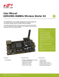
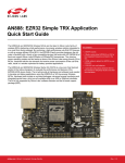
6.3 Step 3 — Animate Segments
Barrel shift right/left
AREGA7
AREGA6
Seg7
AREGA0
Seg6
AREGB7
AREGB6
Seg0
AREGB0
ALOGSEL
Barrel shift right/left
Figure 6.1. Animation Function
The LCD controller contains an animation feature which can animate up to 8 segments (8-segment ring on the LCD display) autonomously. The data displayed in the animated segments is a logic function (AND or OR) of two register bits for each segment. The two
register arrays (LCD_AREGA, LCD_AREGB) can then be set up to be barrelshifted either left or right every time the Frame Counter
overflows. The Frame Counter can be set up to overflow after a configurable number of frames. This is not covered by the LCD driver,
so firmware has to manipulate the LCD registers by doing direct register writes. The following registers must be set up:
LCD_BACTRL:
•
•
•
•
•
•
Set Frame Counter Enable bit
Configure Frame Counter period by setting the FCTOP field
Set Animation Enable bit
Select either AND or OR as logic function
Configure AREGA and AREGB shift direction
For the STK3700, also set the ALOC bit to SEG8TO15
LCD_AREGA/LCD_AREGB:
• Write data used for animation to these registers.
Play around a bit with the configuration of the animated segments and watch the results on the LCD display.
silabs.com | Smart. Connected. Energy-friendly.
Rev. 1.19 | 15
AN0009: Getting Started with EFM32, EZR32, and EFM32 Gemstones
Example 3b — Memory LCD
7. Example 3b — Memory LCD
This example requires an STK equipped with a Memory LCD (e.g. Happy Gecko, Zero Gecko, or Pearl Gecko). This example shows
how to configure the Memory LCD driver and write text on the Memory LCD. The software project called <kit_name>_3_lcd will be used
in this example.
The Board Support Package for the STK includes a driver for the memory LCD. Documentation for this driver is found in the [Kit BSP's
and Drivers] section (scroll to the bottom) under [Software Documentation] in Simplicity Studio.
Figure 7.1. BSP Documentation for the Display Driver
7.1 Step 1 — Configure the Display Driver
First, initialize the DISPLAY driver with DISPLAY_Init().
The Board Support Package includes TEXTDISPLAY, which is an interface for printing text to a DISPLAY device. Use TEXTDISPLAY_Ne
w() to create a new TEXTDISPLAY interface.
7.2 Step 2 — Write Text to the Memory LCD
TEXTDISPLAY implements basic functions for writing text to the Memory LCD. Try TEXTDISPLAY_WriteString() and TEXTDISPLAY_W
riteChar().
silabs.com | Smart. Connected. Energy-friendly.
Rev. 1.19 | 16
AN0009: Getting Started with EFM32, EZR32, and EFM32 Gemstones
Example 4 — Energy Modes
8. Example 4 — Energy Modes
This example shows how to enter different Energy Modes (EMx) and wake up using an RTC interrupt. The project called
<kit_name>_4_energymodes is used in this example.
8.1 Advanced Energy Monitor with a DK
The Development Kits includes current measurement of the VMCU power domain, which is used to power the device and the LCD
display on the MCU board. The VMCU domain is also available on the prototyping board, so other external components in the prototype
can be added to the measurements. The current measurement can be monitored real-time on the TFT display on the main board and
also on a PC using the Energy Profiler available in Simplicity Studio.
8.2 Advanced Energy Monitor with STK
The Starter Kits includes current measurement of the VMCU power domain, which is used to power the device and the LCD display in
addition to other components in the application part of the starter kit. The real-time current measurement can be monitored on a PC
using the Energy Profiler available in Simplicity Studio.
8.3 Step 1 — Enter EM1
To enter EM1, execute a Wait-For-Interrupt instruction. An intrinsic function for this (part of CMSIS) is shown below:
__WFI();
After executing this instruction, observe that the current consumption drops.
8.4 Step 2 — Enter EM2
Entering EM2 is also done by executing the WFI-instruction, except with the SLEEPDEEP bit in the SCB_SCR register also set, and
with a low frequency oscillator enabled. To enter EM2, first enable a low frequency oscillator (either LFRCO or LFXO) before going to
deep sleep. In this example, enable the LFRCO and wait for it to stabilize by using the following emlib function:
void CMU_OscillatorEnable(CMU_Osc_Typedef osc, bool enable, bool wait)
Now, enter EM2 by setting SLEEPDEEP and executing the WFI-instruction:
SCB->SCR |= SCB_SCR_SLEEPDEEP_Msk;
__WFI();
In addition, the EMU emlib functions include functions for entering Energy Modes, which firmware can use instead of setting the
SLEEPDEEP bit and executing the WFI-instruction manually:
void EMU_EnterEM2(bool restore)
Note: When in an active debug session, the device will not be allowed to go below EM1. To measure the current consumption in EM2,
end the debugging session and reset the device with the reset button on the MCU board/STK.
silabs.com | Smart. Connected. Energy-friendly.
Rev. 1.19 | 17
AN0009: Getting Started with EFM32, EZR32, and EFM32 Gemstones
Example 4 — Energy Modes
8.5 Step 3 — Enter EM3
To enter EM3, first disable all low frequency oscillators before going to deep sleep (which is accomplished by using the same technique
as for EM2). Disable the LFRCO originally enabled in Step 2 by using the following emlib function:
void CMU_OscillatorEnable(CMU_Osc_Typedef osc, bool disable, bool wait)
Now, enter EM3 by setting SLEEPDEEP and executing the WFI-instruction:
SCB->SCR |= SCB_SCR_SLEEPDEEP_Msk;
__WFI();
In addition, the EMU emlib functions include functions for entering Energy Modes, which firmware can use instead of disabling LF oscillators, setting the SLEEPDEEP bit, and executing the WFI-instruction manually:
void EMU_EnterEM3(bool restore)
Note: When in an active debug session, the device will not be allowed to go below EM1. To measure the current consumption in EM3,
end the debugging session and reset the device with the reset button on the MCU board/STK.
8.6 Step 4 — Configure the Real-Time Counter
To wake up from EM2, configure the Real-Timer Counter (RTC) to give an interrupt after 5 seconds. First, enable the clock to the RTC
by using the CMU emlib functions. To communicate with Low Energy/Frequency peripherals like the RTC, also enable the clock for the
LE interface (cmuClock_CORE).
The emlib initialization function for the RTC requires a configuration struct as an input:
void RTC_Init(const RTC_Init_TypeDef *init)
The struct is already declared in the code, but firmware must set the 3 parameters in the struct before using it with the RTC_Init function:
rtcInit.comp0Top = true;
Next, set compare value 0 (COMP0) in the RTC, which will set interrupt flag COMP0 when the compare value matches the counter
value. Chose a value that will equal 5 seconds given that the RTC runs at 32.768 kHz:
void RTC_CompareSet(unsigned int comp, uint32_t value)
Now the RTC COMP0 flag will be set on a compare match, but the corresponding enable bit must also be set to generate an interrupt
request from the RTC:
void RTC_IntEnable(uint32_t flags)
The RTC interrupt request is enabled on a comparator match, but to trigger an interrupt, the RTC interrupt request line must be enabled
in the Cortex-M. The IRQn_Type to use is RTC_IRQn.
NVIC_EnableIRQ(RTC_IRQn);
An interrupt handler for the RTC is already included in the code (RTC_IRQHandler), but it is empty. In this function, add a function call
to clear the RTC COMP0 interrupt flag. If firmware does not do this, the Cortex-M will be stuck in the interrupt handler, since the interrupt is never deasserted. Look for the RTC emlib function to clear the interrupt flag.
8.7 Extra Task — Segment LCD Controller in EM2
As an extra task, enable the LCD controller (assuming there's a Segment LCD on the kit in use) and write something on the LCD display before going to EM2. Use the segment animation from the previous example in EM2.
Note: This extra task does not apply to the kits that feature a Memory LCD instead of a segment LCD.
silabs.com | Smart. Connected. Energy-friendly.
Rev. 1.19 | 18
AN0009: Getting Started with EFM32, EZR32, and EFM32 Gemstones
Summary
9. Summary
Congratulations! You now know the basics of Energy Friendly Programming, including register and GPIO operation, use of basic functions on the DK/STK and LCD, in addition to handling different Energy Modes in the device and the emlib/CMSIS functions. The [Software Examples] tile in Simplicity Studio contains several more examples to explore, and additional Application Notes are available using the [Application Notes] tile.
silabs.com | Smart. Connected. Energy-friendly.
Rev. 1.19 | 19
Simplicity Studio
One-click access to MCU and
wireless tools, documentation,
software, source code libraries &
more. Available for Windows,
Mac and Linux!
IoT Portfolio
www.silabs.com/IoT
SW/HW
Quality
Support and Community
www.silabs.com/simplicity
www.silabs.com/quality
community.silabs.com
Disclaimer
Silicon Laboratories intends to provide customers with the latest, accurate, and in-depth documentation of all peripherals and modules available for system and software implementers
using or intending to use the Silicon Laboratories products. Characterization data, available modules and peripherals, memory sizes and memory addresses refer to each specific
device, and "Typical" parameters provided can and do vary in different applications. Application examples described herein are for illustrative purposes only. Silicon Laboratories
reserves the right to make changes without further notice and limitation to product information, specifications, and descriptions herein, and does not give warranties as to the accuracy
or completeness of the included information. Silicon Laboratories shall have no liability for the consequences of use of the information supplied herein. This document does not imply
or express copyright licenses granted hereunder to design or fabricate any integrated circuits. The products must not be used within any Life Support System without the specific
written consent of Silicon Laboratories. A "Life Support System" is any product or system intended to support or sustain life and/or health, which, if it fails, can be reasonably expected
to result in significant personal injury or death. Silicon Laboratories products are generally not intended for military applications. Silicon Laboratories products shall under no
circumstances be used in weapons of mass destruction including (but not limited to) nuclear, biological or chemical weapons, or missiles capable of delivering such weapons.
Trademark Information
Silicon Laboratories Inc., Silicon Laboratories, Silicon Labs, SiLabs and the Silicon Labs logo, CMEMS®, EFM, EFM32, EFR, Energy Micro, Energy Micro logo and combinations
thereof, "the world’s most energy friendly microcontrollers", Ember®, EZLink®, EZMac®, EZRadio®, EZRadioPRO®, DSPLL®, ISOmodem ®, Precision32®, ProSLIC®, SiPHY®,
USBXpress® and others are trademarks or registered trademarks of Silicon Laboratories Inc. ARM, CORTEX, Cortex-M3 and THUMB are trademarks or registered trademarks of
ARM Holdings. Keil is a registered trademark of ARM Limited. All other products or brand names mentioned herein are trademarks of their respective holders.
Silicon Laboratories Inc.
400 West Cesar Chavez
Austin, TX 78701
USA
http://www.silabs.com