1
SRP - 350
RECEIPT PRINTER
Operator’s Manual
All specifications are subjected to change without notice
Warning - U.S.
This equipment has been tested and found to comply with the limits for a Class A digital device
pursuant to Part 15 of the FCC Rules. These limits are designed to provide reasonable protection
against harmful interference when the equipment is operated in a commercial environment. This
equipment generates uses, and can radiate radio frequency energy and , if not installed and used
in accordance with the instruction manual, may cause harmful interference to radio
communications. Operation of this equipment in a residential area is likely to cause harmful
interference in which case the user will be required to correct the interference at his own
expense.
Notice - Canada
This Apparatus complies with class “A” limits for radio interference as specified in the Canadian
department of communications radio interference regulations.
Get appareil est conforme aux normes class “A” d’interference radio tel que specifier par ministre
canadien des communications dans les reglements d’interference radio.
Caution
Some semiconductor devices are easily damaged by static electricity. You should turn the printer
“OFF”, before you connect or remove the cables on the rear side, in order to guard the printer
against the static electricity. If the printer is damaged by the static electricity, you should turn the
printer “OFF”.
INTRODUCTION
The SRP-350, SRP-350S, SRP-350P and SRP-350U Roll Printer are designed for use with
electronic instruments such as system ECR, POS, banking equipment, computer peripheral
equipment, etc.
The main features of the printer are as follows:
1.
High speed printing : 35.5(1/6” Feed) lines per second.
2.
Low noise thermal printing.
3.
RS-232(SRP-350), RS-485(SRP-350S), Parallel(SRP-350P), USB(SRP-350U)
4.
The data buffer allows the unit to receive print data even during printing.
5.
Peripheral units drive circuit enables control of external devices such as cash
drawer.
6.
Characters can be scaled up to 64 times compared to it’s original size.
7.
Bar code printing is possible by using a bar code command.
8.
Different print densities can be selected by DIP switches.
Please be sure to read the instruction in this manual carefully before using your new
SRP-350/SRP-350P.
NOTE : The socket-outlet shall be near the equipment and it
shall be easy accessible.
2
Table of Contents
CHAPTER 1. SETTING UP THE PRINTER ..................................... 4
1-1.
1-2.
1-3.
1-4.
1-5.
1-6.
1-7.
1-8.
UNPACKING ............................................................................ 4
CONNECTING THE CABLES ........................................................... 5
CONNECTING THE COMPUTER ........................................................ 6
CONNECTING THE DRAWER .......................................................... 6
CONNECTING THE POWER SUPPLY .................................................. 7
INSTALLING OR REPLACING THE PAPER ROLL ..................................... 8
ADJUSTMENTS AND SETTINGS ......................................................10
USING THE PRINTER .................................................................11
CHAPTER 2. HEXADECIMAL DUMPING..................................... 14
CHAPTER 3. THE SELF TEST ...................................................... 15
CHAPTER 4. CODE TABLE.......................................................... 16
CHAPTER 5. CONTROL COMMANDS LIST ................................. 24
APPENDIX ................................................................................. 27
A. STAR MODE COMMAND SUMMARY ....................................................27
B. CONNECTORS ............................................................................30
Interface Connector.................................................................31
Drawer Connector ...................................................................34
C. NOTES ....................................................................................34
D. SPECIFICATION ..........................................................................35
3
Chapter 1. Setting Up the Printer
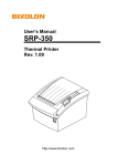
1-1. Unpacking
Your printer box should include these items. If any items are damaged or missing,
please contact your dealer for assistance.
4
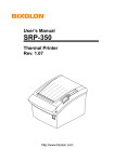
1-2. Connecting the Cables
You can connect up the three cables to the printer. They all connect to the connector
panel on the back of the printer, which is shown below:
Notes : Before connecting any of the cables, make sure that both the printer and the
host are turned off.
5
1-3. Connecting the computer
You need an appropriate interface cable.
1. Plug the cable connector securely into the printer’s interface connector.
2. Tighten the screws on both sides of the cable connector.
3. Attach the other end of the cable to the computer.
1-4. Connecting the Drawer
WARNING:
Use a drawer that matches the printer specification. Using an improper drawer may
damage the drawer as well as the printer.
CAUTION:
Do not connect a telephone line to the drawer kick-out connector; otherwise the
printer and the telephone line may be damaged.
Plug the drawer cable into the drawer kick-out connector on the back of the printer
next to the power supply connector.
6
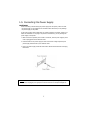
1-5. Connecting the Power Supply
CAUTIONS:
When connecting or disconnecting the power supply from the printer, make sure that
the power supply is not plugged into an electrical outlet. Otherwise you may damage
the power supply or the printer.
If the power supply’s rated voltage and your outlet’s voltage do not match, contact your
dealer for assistance. Do not plug in the power cord. Otherwise, you may damage the
power supply or the printer.
1. Make sure that the printer’s power switch is turned off, and the power supply’s power
cord is unplugged from the electrical outlet.
2. Check the label on the power supply to make sure that the voltage required by the
power supply matches that of your electrical outlet.
3. Plug in the power supply’s cable as shown below. Notice that the flat side of the plug
faces down.
Notes : To remove the DC cable connector, make sure that the power supply’s power
cord is unplugged; then grasp the connector at the arrow and pull it straight out.
7
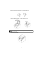
1-6. Installing or Replacing the Paper Roll
Notes : Be sure to use paper rolls that meet the specifications. Do not use paper rolls
that have the paper glued to the core because the printer cannot detect the
paper end correctly.
1. Make sure that the printer is not receiving data; otherwise, data may be lost.
2. Open the paper roll cover by pressing the cover-open button.
Notes : Do not open the print cover while the printer is operating.
This may damage the printer.
3. Remove the used paper roll core if there is one.
4. Insert the paper roll as shown.
8
5. Be sure to note the correct direction that the paper comes off the roll.
6. Pull out a small amount of paper, as shown. Then close the cover.
Notes : When closing the cover, press the center of printer cover firmly to prevent
Paper miss-loading.
7. Tear off the paper as shown.
9
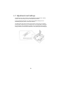
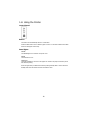
1-7. Adjustments and Settings
The SRP-350 is set up at the factory to be appropriate for almost all users. It does,
however, offer some settings for users with special requirements.
It has DIP switches that allow you to change communication settings, such as
handshaking and parity check, as well as print density.
The SRP-350 also has a near-end sensor for the paper. This can give you a warning
when the paper is almost out. If you find that there is not enough paper remaining on
the roll when the near-end detector is triggered, you can change the near-end sensor
setting. Rotate the near end sensor tab at front or rear position.(See the below figure)
10
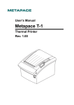
1-8. Using the Printer
Control Panel
Button
The button can be disabled by the ESC c 5 command.
Press the FEED button once to advance paper one line. You can also hold down the FEED
button to feed paper continuously.
Panel lights
POWER
The POWER light is on whenever the printer is on.
ERROR
This indicates an error.
PAPER OUT
This light indicates the near end of the paper roll. Install a new paper roll and the printer
will continue printing.
When the light blinks, it indicates the self-test printing standby state or macro execution
standby state when the macro execution command is used.
11
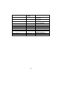
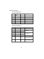
Serial Interface(RS-232C, RS-485) Specification
DIP Switch Set 1 Functions
SW
1
2
3
4
5
6
7
8
FUNCTION
Data Receive Error
Reserved
HandShaking
Word length
Parity check
Parity selection
Baud rate selection
ON
OFF
Ignore
Print ¡ °?¡ ±
XON/OFF
DTR/DSR
7 bits
8 bits
Yes
No
EVEN
ODD
Refer to the Following Table
DEFAULT
OFF
OFF
OFF
OFF
OFF
OFF
ON
OFF
Baud rate selection
Transmission speed
2400 baud
4800 baud
9600 baud
19200 baud
SW – 7
ON
OFF
ON
OFF
SW – 8
ON
ON
OFF
OFF
Dip Switch Set 2 Functions
SW
1
2
3
4
5
6
7
8
FUNCTION
Emulation
Reserved
Reserved
Reserved
Select Print Density
ON
OFF
STAR
EPSON
Refer to the Following Table
Reserved
Reserved
-
-
Print Density
Print Density
1 ( Light )
2
3
4 ( Dark )
SW - 5
ON
OFF
ON
OFF
12
SW – 6
ON
OFF
OFF
ON
DEFAULT
OFF
-
OFF
OFF
-
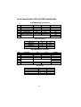
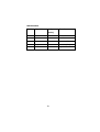
Parallel/USB Interface Specification
Dip Switch Set 1 Functions
SW
1
2
3
4
5
6
7
8
FUNCTION
Reserved
Reserved
Reserved
Reserved
Reserved
Reserved
Reserved
Reserved
ON
-
OFF
-
DEFAULT
OFF
OFF
OFF
OFF
OFF
OFF
OFF
OFF
Dip Switch Set 2 Functions
SW
1
2
3
4
5
6
7
8
FUNCTION
Emulation
Reserved
Reserved
Reserved
Select Print Density
ON
OFF
STAR
EPSON
Refer to the Following Table
Reserved
Reserved
-
-
Print Density
Print Density
1 ( Light )
2
3
4 ( Dark )
SW - 5
ON
OFF
ON
OFF
13
SW – 6
ON
OFF
OFF
ON
DEFAULT
OFF
-
OFF
OFF
-
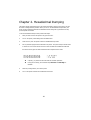
Chapter 2. Hexadecimal Dumping
This feature allows experienced users to see exactly what data is coming to the printer. This can
be useful in finding software problems. When you turn on the hexadecimal dump function, the
printer prints all commands and data in hexadecimal format along with a guide section to help
you find specific commands.
To use the hexadecimal dump function, follow these steps:
1.
After you make sure that the printer is off, open the cover.
2.
Turn on the printer, while holding down the FEED button.
3.
Close the cover, then the printer enters the hexadecimal dump mode.
4.
Run any software program that sends data to the printer. The printer will print all the codes
it receives in a two-column format. The first column contains the hexadecimal codes and
the second column gives the ASCII characters that corresponds to the codes.
1B 21 00 1B 26 02 40 40 40 40
02 0D 1B 44 0A 14 1E 28 28 28
00 01 0A 41 0D 42 0A 43 43 43
.!..&.@@@@
...D....(((
...A.B.CCC
l
A period (.) is printed for each code that has no ASCII equivalent.
l
During the hex dump, all commands except DLE EOT and DLE ENQ are
disabled.
5.
When the printing finishes, turn off the printer.
6.
Turn on the printer and then the hexadecimal mode is off.
14
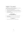
Chapter 3. The self test
The self-test checks whether the printer has any problems. If the printer does not function
properly, contact your dealer. The self-test checks the following;
1.
Make sure paper roll has been installed properly.
2.
Turn on the power while holding down the FEED button. The self-test begins.
3.
The self-test prints the current printer status, which provides the control ROM version
and the DIP switch setting.
4.
After printing the current printer status, self-test printing will print the following, and
pause (The PAPER LED light blinks).
Self-test printing.
Please press the FEED button
5.
Press the FEED button to continue printing. The printer prints a pattern using the
built-in character set.
6.
The self-test automatically ends and cuts the paper after printing the following.
*** COMPLETED ***
The printer is ready to receive data as soon as it completes the self-test.
15
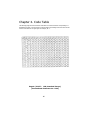
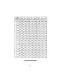
Chapter 4. Code Table
The following pages show the character code tables. To find the character corresponding to a
hexadecimal number, count across the top of the table for the left digit and count down the left
column of the table for the right digit. For example, 4A = J.
Page 0 ( PC437 : USA, Standard Europe)
( International Character Set : USA )
16
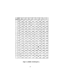
Page 2 ( PC850 : Multilingual )
17
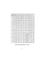
Page 3 ( PC860 : Portuguese )
18
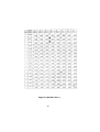
Page 4 ( PC 863 : Canadian - French )
19
Page 5 ( PC 865 : Nordic )
20
Page 19 ( PC 858 : Euro )
21
Page 255 ( Space Page )
22
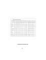
International Character Set
23
Chapter 5. Control Commands List
Control codes
Hexadecimal
codes
<HT>
<LF>
<FF>
09
0A
0C
<CR>
<CAN>
<DLE> <EOT> n
<DLE> <ENQ> n
<ESC> <FF>
<ESC> <SP> n
<ESC> ! n
<ESC> $ nL nH
<ESC> % n
0D
18
10 04 n
10 05 n
1B 0C
1B 20 n
1B 21 n
1B 24 nL nH
1B 25 n
<ESC> & y c1 c2 ..
<ESC> * m nL nH ..
<ESC> - n
<ESC> 2
<ESC> 3 n
<ESC> = n
<ESC> ? n
<ESC> @
<ESC> D n1 ~ nK
<ESC> E n
<ESC> G n
<ESC> J n
<ESC> L
<ESC> M n
<ESC> R n
1B
1B
1B
1B
1B
1B
1B
1B
1B
1B
1B
1B
1B
1B
1B
<ESC> S
<ESC> T n
1B 53
1B 54 n
<ESC> V n
1B 56 n
<ESC> W xL…..
1B 57 ….
26 y c1 c2
2A m nL nH
2D n
32
33 n
3D n
3F n
40
44 … 00
45 n
47 n
4A n
4C
4D n
52 n
24
Function
Horizontal tab
Print and line feed
Print and return to standard
mode in page mode
Print and carriage return
Cancel print data in page mode
Real-time status transmission
Real-time request to printer
Print data in page mode
Set right-side character spacing
Select print modes
Set absolute print position
Select/Cancel user-defined
character set
Define user-defined characters
Select bit-image mode
Turn underline mode on/off
Select default line spacing
Set line spacing
Set peripheral device
Cancel user-defined characters
Initialize printer
Set horizontal tab position
Turn emphasized mode on/off
Turn double-strike mode on/off
Print and feed paper
Select page mode
Select character fonts
Select an international character
set
Select standard mode
Select print direction in page
mode
Turn 90º clockwise rotation mode
on/off
Set printing area in page mode
Control codes
<ESC> \ nL nH
<ESC> a n
<ESC> c 3 n
Hexadecimal
codes
1B 5C n
1B 61 n
1B 63 33 n
<ESC> c 4 n
1B 63 34 n
<ESC> c 5 n
<ESC> d n
<ESC> p m t1 t2
<ESC> t n
<ESC> { n
1B
1B
1B
1B
1B
<FS> p n m
<FS> q n ….
<GS> ! n
<GS> $ nL nH
1C 70 n m
1C 71 n …
1D 21 n
1D 24 nL nH
<GS> * x y …..
<GS> / m
<GS> :
<GS> B n
1D
1D
1D
1D
<GS> H n
1D 48 n
<GS> I n
<GS> L nL nH
<GS> P x y
1D 49 n
1D 4C nL nH
1D 50 x y
<GS>
<GS>
<GS>
<GS>
1D
1D
1D
1D
Vm
Vmn
W nL hH
\ nL nH
63 35 n
64 n
70 m t1 t2
74 n
7B n
2A x y …..
2F n
3A
42 n
56 m
56 m n
57 nL nH
5C nL nH
<GS> ^ r t m
<GS> a n
1D 5E r t m
1D 61 n
<GS> f n
<GS> h n
1D 62 n
1D 68 n
Function
Set relative print position
Select justification
Select paper sensor to output
paper end signals
Select paper sensor to stop
printing
Enable/Disable panel button
Print and feed n lines
Generate pulse
Select character code table
Turn on/off upside-down printing
mode
Print NT bit image
Define NV bit image
Select character size
Set absolute vertical print position
in page mode
Define downloaded bit image
Print downloaded bit image
Start/end macro definition
Turn white/black reverse printing
mode on/off
Select printing position of HRI
characters
Transmit printer ID
Set left margin
Set horizontal and vertical motion
units
Select cut mode and cut paper
Set printing area width
Set relative vertical print position
in page mode
Execute macro
Enable/Disable Automatic status
back
Select font for HRI characters
Set bar code height
25
Control codes
<GS>
<GS>
<GS>
<GS>
<GS>
k m ….NUL
kmn…
rn
v 0 m ….
wn
Hexadecimal
codes
1D
1D
1D
1D
1D
6B m… NUL
6B m n …
72 n
76 30
77 n
26
Function
Print bar code
Transmit status
Print raster bit image
Set bar code width
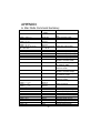
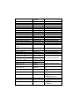
APPENDIX
A. Star Mode Command Summary
Control codes
Hexadecimal
codes
<ESC> ”R” n
1B 52 n
<ESC> <GS> t n
<ESC> ”/” “1”
<ESC> ”/” <1>
<ESC> ”/” “0”
<ESC> ”/” <0>
<ESC> “b” n1 n2 n3 n4
d1 … dk <RS>
<ESC> ”M”
<ESC> ”p”
<ESC> ”P”
<ESC> ”:”
<ESC> <SP> n
<SO>
1B 1D 74n
1B 2F 31
1B 2F 01
1B 2F 30
1B 2F 00
1B 62 n1 n2 n3 n4
d1 … dk 1E
1B 4D
1B 70
1B 50
1B 3A
1B 20 n
0E
<DC4>
14
<ESC> “W” n
1B 57 n
<ESC> <SO>
1B 0E
<ESC> <DC4>
1B 14
<ESC> “h” n
1B 68 n
<ESC> ”-“ “1”
<ESC> ”-:” <1>
<ESC> “_” “1”
<ESC> “_” <1>
<ESC> “4”
<ESC> “5”
<SI>
<DC2>
<ESC> “E”
<ESC> “F”
<ESC> “C” n
<ESC> “C” <0> n
<ESC> “N” n
<ESC> “O”
1B
1B
1B
1B
1B
1B
0F
12
1B
1B
1B
1B
1B
1B
2D 31
2D 01
5F 31
5F 01
34
35
45
46
43 n
43 00 n
4E n
4F
27
Function
Select international character
set
Select character table
Select slash zero
Select normal zero
Select bar code printing
Select 12-dot pitch printing
Select 14-dot pitch printing
Select 15-dot pitch printing
Select 16-dot pitch printing
Set character spacing
Sets the printing magnified
double in character width.
Resets the printing magnified
in character width.
Sets the magnification rate in
character width.
Sets the printing magnified
double in character height.
Resets the printing magnified
in character height.
Sets the magnification rate in
character height.
Select underlining
Select overlining
Select highlight printing
Cancel highlight printing
Inverted printing
Cancel inverted printing
Select emphasized printing
Cancel emphasized printing
Set page length in lines
Set page length in inches
Set bottom margin
Cancel bottom margin
Control codes
Hexadecimal
codes
Function
<ESC> “I” n
<ESC> “Q” n
<LF>
<ESC> “a” n
<FF>
<HT>
<VT>
<ESC> “z” “1”
<ESC> “0”
<ESC> “J” n
<ESC> “I” n
<ESC> “B” n1 n2…<0>
<ESC> “D” n1 n2…<0>
<ESC> <GS> “A” n1 n2
<ESC> <GS> “R” n1 n2
<ESC> <GS> “a” n
<ESC> “K” n <0>
m1 m2 …
<ESC> “L” n <0>
m1 m2 …
<ESC> “k” n <0> d1
<ESC> “X” n1 n2
<ESC> <FS> “p” n m
<ESC> “&” ”1” ”1”
n m1 m2 … m48
<ESC> “&” <1> <1>
n m1 m2 … m48
<ESC> “&” ”1” ”0” n
<ESC> “&” <1> <0> n
<ESC> “%” “1”
<ESC> “%” <1>
<ESC> “%” “0”
<ESC> “%” <0>
<ESC> <GS> “*” xy
1B 6C n
1B 51 n
0A
1B 61 n
0C
09
0B
1B 7A 31
1B 30
1B 4A n
1B 49 n
1B 42 n1 n2 … 00
1B 44 n1 n2 … 00
1B 1D 41 n1 n2
1B 1D 52 n1 n2
1B 1D 61 n
1B 48 n 00 m1 m2
Set left margin
Set right margin
Line Feed
Feed paper n lines
Form Feed
Horizontal tab
Vertical tab
Set line spacing to 4 mm
Set line spacing to 3 mm
One time n/4 mm feed
One time n/8 mm feed
Set vertical tab stops
Set horizontal tab stops
Absolute position setting
Relative position setting
Alignment
Print normal density graphics
1B 4C n1 n2 m1
m2
1B 6B n 00 d1
1B 58 n1 n2
1B 1C 70 n m
1B 26 31 31 n
m1 m2 … m48
1B 26 01 01
n m1 m2 … m48
1B 26 31 30 n
1B 26 01 00 n
1B 25 31
1B 25 01
1B 25 30
1B 25 00
1B 1D 2A 78 79
Print high density graphics
<ESC> <GS> “/” m
1B 1D 2F 6D
<ESC> <BEL> n1 n2
1B 07 n1 n2
<BEL>
<FS>
07
1C
<EM>
19
28
Print fine density graphics
Print fine density graphics
Print NV bit image
Define download character
Delete a download character
Enable download character
set
Disable download character
set
Definition of download bit
image
Printing of download bit
image
Define drive pulse width for
peripheral device #1.
Control peripheral device #1
Control peripheral device #1
immediately.
Control peripheral device #2
immediately
Control codes
Hexadecimal
codes
<SUB>
1A
<ESC> “d” n
1B 64 n
<CAN>
18
<DC3>
<DC1>
<RS>
<ESC> “@”
<ENQ>
<EOT>
<ESC> “?” <LF> <NUL>
13
11
1E
1B 40
05
04
1B 3F 0A 00
<ESC> “8” n1 n2
<ESC> “9” n1 n2
1B 38 n1 n2
1B 39 n1 n2
29
Function
Control peripheral device #2
immediately
Partial-cut command to the
auto cutter.
Cancel last line & initialize
printer immediately
Deselect printer
Set select mode
Beep the buzzer
Initialize printer
Inquiry (Status inquiry)
Near end status inquiry
Reset printer hardware
(Perform test print)
Registers a logo pattern
Prints a logo pattern
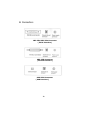
B. Connectors
SRP-350/SRP-350S Connector
( Serial Interface )
SRP-350P Connector
( Parallel Interface )
SRP-350U Connector
( USB Interface )
30
Interface Connector
Serial Interface(RS-232)
Pin No.
Signal
name
Direction
Function
1
FG
-
Frame Ground
2
TxD
Output
Transmit Data
3
RxD
Input
Receive Data
6
DSR
Input
Data Set Ready
7
SG
-
Signal Ground
20
DTR
Output
Data Terminal Ready
Serial Interface(RS-485)
Pin No.
Signal Name
Direction
Function
1
FGND
-
Frame Ground
2
SD2
Output
3
SD1
Output
4
RD2
Input
5
RD1
Input
7
SGND
-
Signal Ground
8
DR2
9
DR1
Output
Same as DTR(RS-232)
10
CS2
11
CS1
Input
Same as DSR(RS-232)
31
Send Data
Receive Data
Parallel Interface(IEEE-1284)
Pin No. Source
Compatibility
Mode
Nibble
Mode
Byte Mode
1
Host
nStrobe
HostClk
HostClk
2
Host / Printer
Data 0 (LSB)
-
Data 0 (LSB)
3
Host / Printer
Data 1
-
Data 1
4
Host / Printer
Data 2
-
Data 2
5
Host / Printer
Data 3
-
Data 3
6
Host / Printer
Data 4
-
Data 4
7
Host / Printer
Data 5
-
Data 5
8
Host / Printer
Data 6
-
Data 6
9
Host / Printer
Data 7 (MSB)
-
Data 7 (MSB)
10
Printer
nAck
PtrClk
PtrClk
11
Printer
Busy
PtrBusy
/Data3,7
PtrBusy
12
Printer
Perror
AckDataReq
/Data2,6
AckDataReq
13
Printer
Select
Xflag
/Data1,5
Xflag
14
Host
nAutoFd
HostBusy
HostBusy
15
NC
NC
NC
16
GND
GND
GND
17
FG
FG
FG
Logic-H
Logic-H
Logic-H
GND
GND
GND
18
Printer
19~30
31
Host
nInit
nInit
nInit
32
Printer
nFault
nDataAvail
/Data0,4
nDataAvail
GND
ND
ND
33
34
Printer
DK_Status
ND
ND
35
Printer
+5V
ND
ND
36
Host
nSelectIn
32
1284-Active
1284-Active
USB Interface
Pin No.
Signal Name
Assignment
Function
(Color)
Shell
Shield
Drain Wire
Frame Ground
1
VBUS
Red
Host Power
2
D-
White
Data Line(D-)
3
D+
Green
Data Line(D+)
4
GND
Black
Signal Ground
33
Drawer Connector
Pin No.
Signal name
Direction
1
Frame ground
-
2
Drawer kick- out drive signal 1
Output
3
Drawer open/close signal
Input
4
+24V
-
5
Drawer kick- out drive signal 2
Output
6
Signal ground
-
C. Notes
Paper dust inside the printer may lower the print quality. In this
case clean the printer as follows.
1) Open the printer cover and remove the paper if exists.
2) Clean the print head with a cotton swab moistened with
alcohol solvent.
3) Clean the platen roller and paper end sensor with cotton
swab moistened with water.
4) Insert a paper roll and close the printer cover.
The remained amount of paper detected by paper near end sensor
varies with the diameter of the paper core.
To adjust the remained amount, contact your dealer.
34
D. Specification
Printing method
Thermal line printing
Dot density
180 X 180 dpi (7dots/mm)
Printing width
72.192 +0.2mm or –0.2mm
Paper width
Characters per line (default)
79 ~ 80 mm
42 (Font A)
56 (Font B)
Printing speed
35.5 lines/sec(1/6” Feed)
150 mm/sec
Receive Buffer Size
4K Bytes
NOTE : Printing speed may be slower, depending on the data
transmission speed and the combination of control commands.
Supply voltage
Environmental
conditions
Input voltage
120/230 VAC
Frequency
50/60 Hz
Output voltage
+24 VDC
Temperature
5 ~ 45 oC (Operating)
-10 ~ 50 oC (Storage)
Humidity
30 ~ 80 % RH (Operating)
10 ~ 90 % RH (Storage)
; Except for paper
LIFE *
MCBF *
Mechanism
Head
15,000,000 lines
1x10⁸ pulse
(Approximately 100 Km)
Auto Cutter
1,000,000 Cut
Mechanism
37,000,000 lines
* These values are calculated under printing level 2 with
recommended paper at normal temperature.
* These values may vary with environment temperature, printing
level, etc.
35