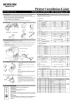
1
Safety Precautions
SRP-350 Ver.2
In using the present appliance, please keep the following safety
regulations in order to prevent any hazard or material damage.
WARNING
Violating following instructions can cause serious injury or death.
Do not plug several products in one
multi-outlet.
RECEIPT PRINTER
You must use only the supplied adapter.
It is dangerous to use other adapters.
This can provoke over-heating and a fire.
If the plug is wet or dirty, dry or wipe it
before usage.
If the plug does not fit perfectly with the
outlet, do not plug in.
Be sure to use only standardized
multi-outlets.
ONLY SUPPLIED ADAPTER
PROHIBITE
Keep the plastic bag out of children’s reach.
Do not pull the cable to unplug.
If not, a child may put the bag on his head.
This can damage the cable, which is the
origin of a fire or a breakdown of the printer.
PROHIBITE
PROHIBITE
Do not plug in or unplug with your hands
wet.
If you observe a strange smoke, odor or
noise from the printer, unplug it before
taking following measures.
You can be electrocuted.
Switch off the printer and unplug the set from
the mains.
After the disappearance of the smoke, call
your dealer to repair it.
PROHIBITE
Operator’s Manual
Do not bend the cable by force or leave it
under any heavy object.
A damaged cable can cause a fire.
TO UNPLUG
PROHIBITE
All specifications are subjected to change without notice
http://www.samsungminiprinters.com
1
PRINTER
Warning - U.S.
WARNING
Violating following instructions can cause slight wound or damage the
appliance.
Keep the desiccant out of children’s
reach.
Install the printer on the stable surface.
If the printer falls down, it can be broken
and you can hurt yourself.
If not, they may eat it.
This equipment has been tested and found to comply with the limits for a Class A digital
device pursuant to Part 15 of the FCC Rules. These limits are designed to provide
reasonable protection against harmful interference when the equipment is operated in a
commercial environment. This equipment generates uses, and can radiate radio frequency
energy and, if not installed and used in accordance with the instruction manual, may cause
harmful interference to radio communications. Operation of this equipment in a residential
area is likely to cause harmful interference in which case the user will be required to
correct the interference at his own expense.
Notice - Canada
PROHIBITE
PROHIBITE
This Apparatus complies with class “A” limits for radio interference as specified in the
Canadian department of communications radio interference regulations.
PRINTER
Get appareil est conforme aux normes class “A” d’interference radio tel que specifier par
ministre canadien des communications dans les reglements d’interference radio.
Use only approved accessories and do
not try to disassemble, repair or remodel
it for yourself.
Do not touch the HEAD of printer with
your hand.
This can burn your hand or deteriorate
printing quality.
Call your dealer when you need these
services.
The SRP-350, SRP-350S, SRP-350P and SRP-350U Roll Printer are designed for use with
electronic instruments such as system ECR, POS, banking equipment, computer peripheral
equipment, etc.
PROHIBITE
PRINER
Some semiconductor devices are easily damaged by static electricity. You should turn the
printer “OFF”, before you connect or remove the cables on the rear side, in order to guard
the printer against the static electricity. If the printer is damaged by the static electricity,
you should turn the printer “OFF”.
INTRODUCTION
HEAD
DISASSEMBLING
PROHIBITED
Caution
The main features of the printer are as follows:
Do not let water or other foreign objects
in the printer.
Do not use the printer when it is out of
order. This can cause a fire or an
electrocution.
If this happened, switch off and unplug the
printer before calling your dealer.
Switch off and unplug the printer before
calling your dealer.
1.
2.
3.
4.
5.
6.
7.
8.
PROHIBITE
PRINTER
Please be sure to read the instruction in this manual carefully before using your new
SRP-350/SRP-350P.
TO UNPLUG
PRINTER
DEALER
2
High speed printing : 35.5(1/6” Feed) lines per second.
Low noise thermal printing.
RS-232(SRP-350), RS-485(SRP-350S), Parallel(SRP-350P),
USB(SRP-350U)
The data buffer allows the unit to receive print data even during printing.
Peripheral units drive circuit enables control of external devices such as
cash drawer.
Characters can be scaled up to 64 times compared to it’s original size.
Bar code printing is possible by using a bar code command.
Different print densities can be selected by DIP switches.
NOTE : The socket-outlet shall be near the equipment and it
shall be easy accessible.
3
Table of Contents
Chapter 1. Setting Up the Printer
CHAPTER 1. SETTING UP THE PRINTER ..................................... 5
1-1. UNPACKING .............................................................................. 5
1-2. CONNECTING THE CABLES ............................................................. 6
1-3. CONNECTING THE COMPUTER ......................................................... 7
1-4. CONNECTING THE DRAWER ........................................................... 7
1-5. CONNECTING THE POWER SUPPLY ................................................... 8
1-6. INSTALLING OR REPLACING THE PAPER ROLL ...................................... 9
1-7. ADJUSTMENTS AND SETTINGS ...................................................... 11
1-8. USING THE PRINTER .................................................................. 12
1-1. Unpacking
Your printer box should include these items. If any items are damaged or missing,
please contact your dealer for assistance.
CHAPTER 2. HEXADECIMAL DUMPING ..................................... 15
CHAPTER 3. THE SELF TEST ...................................................... 16
CHAPTER 4. CODE TABLE .......................................................... 17
CHAPTER 5. CONTROL COMMANDS LIST.................................. 25
###########
APPENDIX ................................................................................. 50
A. STAR MODE COMMAND SUMMARY .................................................... 50
B. CONNECTORS ............................................................................. 53
SRP-350/350P
Cover Cable
RS-232C Cable Connector ......................................................... 54
Interface Connector.................................................................. 55
Drawer Connector .................................................................... 57
C. NOTES ..................................................................................... 57
D. SPECIFICATION ........................................................................... 58
Roll Paper
4
Operator’s manual
AC Adapter
5
Power Code
1-2. Connecting the Cables
You can connect up the three cables to the printer. They all connect to the connector
panel on the back of the printer, which is shown below:
1-3. Connecting the computer
You need an appropriate interface cable.
1. Plug the cable connector securely into the printer’s interface connector.
2. Tighten the screws on both sides of the cable connector.
3. Attach the other end of the cable to the computer.
1-4. Connecting the Drawer
Notes : Before connecting any of the cables, make sure that both the printer and the
host are turned off.
WARNING:
Use a drawer that matches the printer specification. Using an improper drawer may
damage the drawer as well as the printer.
CAUTION:
Do not connect a telephone line to the drawer kick-out connector; otherwise the
printer and the telephone line may be damaged.
Plug the drawer cable into the drawer kick-out connector on the back of the printer
next to the power supply connector.
6
7
1-5. Connecting the Power Supply
CAUTIONS:
When connecting or disconnecting the power supply from the printer, make sure that
the power supply is not plugged into an electrical outlet. Otherwise you may damage
the power supply or the printer.
If the power supply’s rated voltage and your outlet’s voltage do not match, contact
your dealer for assistance. Do not plug in the power cord. Otherwise, you may damage
the power supply or the printer.
1-6. Installing or Replacing the Paper Roll
Notes : Be sure to use paper rolls that meet the specifications. Do not use paper
rolls that have the paper glued to the core because the printer cannot
detect the paper end correctly.
1. Make sure that the printer is not receiving data; otherwise, data may be lost.
2. Open the paper roll cover by pressing the cover-open button.
1. Make sure that the printer’s power switch is turned off, and the power supply’s
power
cord is unplugged from the electrical outlet.
2. Check the label on the power supply to make sure that the voltage required by the
power supply matches that of your electrical outlet.
3. Plug in the power supply’s cable as shown below. Notice that the flat side of the
plug faces down.
Notes : Do not open the print cover while the printer is operating.
This may damage the printer.
3. Remove the used paper roll core if there is one.
4. Insert the paper roll as shown.
Notes : To remove the DC cable connector, make sure that the power supply’s power
cord is unplugged; then grasp the connector at the arrow and pull it straight out.
8
9
5. Be sure to note the correct direction that the paper comes off the roll.
1-7. Adjustments and Settings
The SRP-350 is set up at the factory to be appropriate for almost all
users. It does, however, offer some settings for users with special
requirements.
It has DIP switches that allow you to change communication settings,
such as handshaking and parity check, as well as print density.
6. Pull out a small amount of paper, as shown. Then close the cover.
The SRP-350 also has a near-end sensor for the paper. This can give
you a warning when the paper is almost out. If you find that there is
not enough paper remaining on the roll when the near-end sensor is
triggered, you can change the near-end sensor setting. Rotate the
near end sensor tab at front or rear position.(See the below figure)
Notes : When closing the cover, press the center of printer cover firmly to prevent
paper miss-loading
7. Tear off the paper as shown.
10
11
1-8. Using the Printer
Serial Interface(RS-232C, RS-485) Specification
Control Panel
DIP Switch Set 1 Functions
SW
1
FUNCTION
Auto Line Feed
2
3
4
5
6
7
8
Reserved
Handshaking
Word length
Parity check
Parity selection
Baud rate selection
ON
OFF
Always
Always
Enabled
Disabled
XON/OFF
DTR/DSR
7 bits
8 bits
Yes
No
EVEN
ODD
Refer to the Following Table
DEFAULT
OFF
OFF
OFF
OFF
OFF
OFF
ON
OFF
Baud rate selection
Transmission speed
2400 baud
4800 baud
9600 baud
19200 baud
Button
The button can be disabled by the ESC c 5 command.
Press the FEED button once to advance paper one line. You can also hold down the
FEED button to feed paper continuously.
Panel lights
SW – 7
ON
OFF
ON
OFF
SW – 8
ON
ON
OFF
OFF
Dip Switch Set 2 Functions
POWER
The POWER light is on whenever the printer is on.
ERROR
This indicates an error.
PAPER OUT
This light indicates the near end of the paper roll. Install a new paper roll and the
printer Will continue printing.
SW
1
2
3
4
5
6
7
8
FUNCTION
Emulation
Reserved
Reserved
Reserved
Select Print Density
ON
OFF
STAR
EPSON
Refer to the Following Table
Reserved
Reserved
When the light blinks, it indicates the self-test printing standby state or macro
execution Standby state when the macro execution command is used.
-
-
Print Density
Print Density
1 ( Light )
2
3
4 ( Dark )
12
SW - 5
ON
OFF
ON
OFF
13
SW – 6
ON
OFF
OFF
ON
DEFAULT
OFF
-
OFF
OFF
-
Parallel/USB Interface Specification
Chapter 2. Hexadecimal Dumping
Dip Switch Set 1 Functions
SW
1
FUNCTION
Auto Line Feed
2
3
4
5
6
7
8
Reserved
Reserved
Reserved
Reserved
Reserved
Reserved
Reserved
ON
Always
Enabled
-
OFF
Always
Disabled
-
DEFAULT
OFF
OFF
OFF
OFF
OFF
OFF
OFF
OFF
Dip Switch Set 2 Functions
SW
1
2
3
4
5
6
7
8
FUNCTION
Emulation
Reserved
Reserved
Reserved
Select Print Density
ON
OFF
STAR
EPSON
Refer to the Following Table
Reserved
Reserved
-
-
This feature allows experienced users to see exactly what data is coming to the printer.
This can be useful in finding software problems. When you turn on the hexadecimal dump
function, the printer prints all commands and data in hexadecimal format along with a
guide section to help you find specific commands.
To use the hexadecimal dump function, follow these steps:
1.
After you make sure that the printer is off, open the cover.
2.
Turn on the printer, while holding down the FEED button.
3.
Close the cover, then the printer enters the hexadecimal dump mode.
4.
Run any software program that sends data to the printer. The printer will print all the
codes it receives in a two-column format. The first column contains the hexadecimal
DEFAULT
OFF
-
codes and the second column gives the ASCII characters that corresponds to the
codes.
OFF
OFF
-
1B 21 00 1B 26 02 40 40 40 40
02 0D 1B 44 0A 14 1E 28 28 28
00 01 0A 41 0D 42 0A 43 43 43
Print Density
Print Density
1 ( Light )
2
3
4 ( Dark )
SW - 5
ON
OFF
ON
OFF
14
SW – 6
ON
OFF
OFF
ON
.!..&.@@@@
...D....(((
...A.B.CCC
z
A period (.) is printed for each code that has no ASCII equivalent.
z
During the hex dump, all commands except DLE EOT and DLE ENQ are
disabled.
5.
When the printing finishes, turn off the printer.
6.
Turn on the printer and then the hexadecimal mode is off.
15
Chapter 3. The self test
Chapter 4. Code Table
The self-test checks whether the printer has any problems. If the printer does not function
properly, contact your dealer. The self-test checks the following;
The following pages show the character code tables. To find the character corresponding
to a hexadecimal number, count across the top of the table for the left digit and count
down the left column of the table for the right digit. For example, 4A = J.
1.
Make sure paper roll has been installed properly.
2.
Turn on the power while holding down the FEED button. The self-test begins.
3.
The self-test prints the current printer status, which provides the control ROM version
and the DIP switch setting.
4.
After printing the current printer status, self-test printing will print the following, and
pause (The PAPER LED light blinks).
Self-test printing.
Please press the FEED button
5.
Press the FEED button to continue printing. The printer prints a pattern using the
built-in character set.
6.
The self-test automatically ends and cuts the paper after printing the following.
*** COMPLETED ***
The printer is ready to receive data as soon as it completes the self-test.
Page 0 ( PC437 : USA, Standard Europe)
( International Character Set : USA )
16
17
Page 3 ( PC860 : Portuguese )
Page 2 ( PC850 : Multilingual )
18
19
Page 4 ( PC 863 : Canadian - French )
20
Page 5 ( PC 865 : Nordic )
21
Page 19 ( PC 858 : Euro )
Page 255 ( Space Page )
22
23
Chapter 5. Control Commands List
Control codes
Hexadecimal
Codes
<HT>
<LF>
<FF>
09
0A
0C
<CR>
<CAN>
<DLE> <EOT> n
<DLE> <ENQ> n
<ESC> <FF>
<ESC> <SP> n
<ESC> ! n
<ESC> $ nL nH
<ESC> % n
<ESC> & y c1 c2 ..
<ESC> * m nL nH ..
<ESC> - n
<ESC> 2
<ESC> 3 n
<ESC> = n
<ESC> ? n
<ESC> @
<ESC> D n1 ~ nK
<ESC> E n
<ESC> G n
<ESC> J n
<ESC> L
<ESC> M n
<ESC> R n
<ESC> S
<ESC> T n
<ESC> V n
<ESC> W xL…..
<ESC> ₩ nL nH
<ESC> a n
0D
18
10 04 n
10 05 n
1B 0C
1B 20 n
1B 21 n
1B 24 nL nH
1B 25 n
1B 26 y c1 c2
1B 2A m nL nH
1B 2D n
1B 32
1B 33 n
1B 3D n
1B 3F n
1B 40
1B 44 … 00
1B 45 n
1B 47 n
1B 4A n
1B 4C
1B 4D n
1B 52 n
1B 53
1B 54 n
1B 56 n
1B 57 ….
1B 5C n
1B 61 n
Function
Horizontal tab
Print and line feed
Print and return to standard mode in
page mode
Print and carriage return
Cancel print data in page mode
Real-time status transmission
Real-time request to printer
Print data in page mode
Set right-side character spacing
Select print modes
Set absolute print position
Select/Cancel user-defined character set
Define user-defined characters
Select bit-image mode
Turn underline mode on/off
Select default line spacing
Set line spacing
Set peripheral device
Cancel user-defined characters
Initialize printer
Set horizontal tab position
Turn emphasized mode on/off
Turn double-strike mode on/off
Print and feed paper
Select page mode
Select character fonts
Select an international character set
Select standard mode
Select print direction in page mode
Turn 90º clockwise rotation mode on/off
Set printing area in page mode
Set relative print position
Select justification
International Character Set
24
25
Control codes
Hexadecimal
codes
<ESC> c 3 n
1B 63 33 n
<ESC> c 4 n
<ESC> c 5 n
<ESC> d n
<ESC> p m t1 t2
<ESC> t n
<ESC> { n
<FS> p n m
<FS> q n ….
<GS> ! n
<GS> $ nL nH
1B 63 34 n
1B 63 35 n
1B 64 n
1B 70 m t1 t2
1B 74 n
1B 7B n
1C 70 n m
1C 71 n …
1D 21 n
1D 24 nL nH
<GS>
<GS>
<GS>
<GS>
* x y …..
/m
:
Bn
1D
1D
1D
1D
2A x y …..
2F n
3A
42 n
<GS>
<GS>
<GS>
<GS>
<GS>
<GS>
<GS>
<GS>
Hn
In
L nL nH
Pxy
Vm
Vmn
W nL hH
₩ nL nH
1D
1D
1D
1D
1D
1D
1D
1D
48 n
49 n
4C nL nH
50 x y
56 m
56 m n
57 nL nH
5C nL nH
<GS>
<GS>
<GS>
<GS>
^rtm
an
fn
hn
1D
1D
1D
1D
5E r t m
61 n
62 n
68 n
<GS>
<GS>
<GS>
<GS>
<GS>
k m ….NUL
kmn…
rn
v 0 m ….
wn
1D 6B m… NUL
1D 6B m n …
1D 72 n
1D 76 30
1D 77 n
Function
Command Notation
Select paper sensor to output paper end
signals
Select paper sensor to stop printing
Enable/Disable panel button
Print and feed n lines
Generate pulse
Select character code table
Turn on/off upside-down printing mode
Print NT bit image
Define NV bit image
Select character size
Set absolute vertical print position in
page mode
Define downloaded bit image
Print downloaded bit image
Start/end macro definition
Turn white/black reverse printing mode
on/off
Select printing position of HRI characters
Transmit printer ID
Set left margin
Set horizontal and vertical motion units
Select cut mode and cut paper
[Name]
[Format]
Set printing area width
Set relative vertical print position in page
mode
Execute macro
Enable/Disable Automatic status back
Select font for HRI characters
Set bar code height
[Description]
Print bar code
Transmit status
Print raster bit image
Set bar code width
[Range]
[Description]
Explanation of Terms
LSB
Least Significant Bit
HT
[Name]
[Format]
[Description]
Horizontal tab.
ASCII
HT
Hex
09
Decimal
9
Moves the print position to the next horizontal tab position.
LF
[Name]
[Format]
Print and line feed.
ASCII
LF
Hex
0A
Decimal
10
Prints the data in the print buffer and feeds one line based on the current
line spacing.
FF
[Name]
[Format]
[Description]
Print and return to standard mode in page mode.
ASCII
FF
Hex
0C
Decimal
12
Prints the data in the print buffer collectively and returns to standard mode.
CR
[Name]
[Format]
[Description]
26
The name of the command.
The code sequence. ASCII Indicates the ASCII equivalents.
Hex indicates the hexadecimal equivalents.
Decimal indicates the decimal equivalents.
[ ] k indicates the contents of the [ ] should be repeated k times.
Gives the allowable ranges for the arguments.
Describes the function of the command.
Print and carriage return.
ASCII
CR
Hex
0D
Decimal
13
When automatic line feed is enabled, this command functions the same as
LF : when automatic line feed is disabled, this command is ignored.
27
CAN
[Name]
[Format]
[Description]
Cancel print data in page mode.
ASCII
CAN
Hex
18
Decimal
24
In page mode, deletes all the print data in the current printable area.
DLE EOT n
[Name]
[Format]
[Range]
[Description]
Bit
0
1
2
3
4
5-6
7
Bit
0
1
2
3
4
5
6
7
Bit 5 :
Real-time status transmission.
ASCII
DLE
EOT
n
Hex
10
04
n
Decimal
16
4
n
1 ≤n ≤4
Transmits the selected printer status specified by n in real-time, according
to the following parameters :
n = 1 : Transmit printer status. n = 2 : Transmit off-line status.
n = 3 : Transmit error status.
n = 4 : Transmit paper roll sensor status.
Off/On
Off
On
Off
On
Off
On
On
Off
Hex
00
02
00
04
00
08
10
00
Decimal
0
2
0
4
0
8
16
0
n = 1 : Printer status
Function
Not used. Fixed to Off.
Not used. Fixed to On.
Drawer open/close signal is LOW (connector pin 3).
Drawer open/close signal is HIGH (connector pin 3).
On-Line
Off-Line
Not used. Fixed to On.
Undefined.
Not used. Fixed to Off.
Off/On
Off
On
Off
On
Off
On
On
Off
On
Off
On
Off
Hex
00
02
00
04
00
08
10
00
20
00
40
00
Decimal
0
2
0
4
0
8
16
0
32
00
64
0
n = 2 : Off-line status
Function
Not used. Fixed to Off.
Not used. Fixed to On.
Cover is closed.
Cover is open.
Paper is not being fed by using the PAPER FEED button.
Paper is being fed by the PAPER FEED button.
Not used. Fixed to On.
No paper-end stop.
Printing stops due to paper end.
No error.
Error occurs.
Not used. Fixed to Off.
n = 3 : Error status
Off/On Hex Decimal Function
Off
00
0
Not used. Fixed to Off.
On
02
2
Not used. Fixed to On.
Undefined.
Off
00
0
No auto-cutter error.
On
08
8
Auto-cutter error occurs.
4
On
10
16
Not used. Fixed to On.
5
Off
00
0
No unrecoverable error.
On
20
32
Unrecoverable error occurs.
6
Off
00
0
No auto-recoverable error.
On
40
64
Auto recoverable error occurs.
7
Off
00
0
Not used. Fixed to Off.
Bit 3 :
If these errors occur due to paper jams or the like, it is possible to recover by
correcting the cause of the error and executing DLE ENQ n (1 ≤n ≤2).
Bit
0
1
2
3
Bit 6 :
When printing is stopped due to high print head temperature until the print
head temperature drops sufficiently or when the paper roll cover is open during
printing, bit 6 is on.
Bit
0
1
2
3
Off/On
Off
On
Off
On
Hex
00
02
00
0C
Decimal
0
2
0
12
4
5
6
On
Off
On
10
00
60
16
0
96
7
Off
00
0
n = 4 : Continuous paper sensor status
Function
Not used. Fixed to Off.
Not used. Fixed to On.
Paper roll Near-END sensor : Paper adequate.
Paper near-end is detected by the paper roll
Near-END sensor.
Not used. Fixed to On.
Paper roll end sensor : Paper present.
Paper roll end detected by the paper roll-end
sensor.
Not used. Fixed to Off.
DLE ENQ n
[Name]
[Format]
[Range]
[Description]
Real-time request to printer.
ASCII
DLE
ENQ
n
Hex
10
05
n
Decimal
16
5
n
1 ≤n ≤2
Recovers from an error and restart printing from the line where the error
occurred.
Becomes on when the paper end sensor detects paper end and printing stops.
28
29
ESC FF
[Name]
[Format]
[Description]
ESC $ nL nH
Print data in page mode.
ASCII
ESC
FF
Hex
1B
0C
Decimal
27
12
In page mode, prints all buffered data in the printing area collectively.
ESC SP n
[Name]
[Format]
[Range]
[Description]
[Range]
[Description]
Bit
0
1,2
3
4
5
6
7
[Range]
[Description]
Set right-side character spacing.
ASCII
ESC
SP
n
Hex
1B
20
n
Decimal
27
32
n
0 ≤n ≤255
Sets the character spacing for the right side of the character to
[n ×horizontal or vertical motion units].
ESC ! n
[Name]
[Format]
[Name]
[Format]
Select print modes.
ASCII
ESC
!
Hex
1B
21
Decimal
27
33
0 ≤n ≤255
Selects print mode(s) using
Off/On
Off
On
Off
On
Off
On
Off
On
Off
On
Hex
00
01
00
08
00
10
00
20
00
80
Decimal
0
1
0
8
0
16
0
32
0
128
n
n
n
n as follows.
Function
Character font(12 ×24) selected.
Character font(9 ×17) selected.
Undefined.
Emphasized mode not selected.
Emphasized mode selected.
Double-height mode not selected.
Double-height mode selected.
Double-width mode not selected.
Double-width mode selected.
Undefined.
Underline mode not selected.
Underline mode selected.
30
Set absolute print position.
ASCII
ESC
$
nL
n
Hex
1B
24
nL
n
Decimal
27
36
nL
n
0 ≤n ≤255
0 ≤n ≤255
Set the distance from the beginning of the line to the position at which
subsequent characters are to be printed.
* The distance from the beginning of the line to the print position is
[(nL + nH ×256) ×(vertical or horizontal notion unit)] inches.
ESC % n
[Name]
[Format]
[Range]
[Description]
Select / Cancel user-defined character set.
ASCII
ESC
%
n
Hex
1B
25
n
Decimal
27
37
n
0 ≤n ≤255
Selects or cancels the user-defined character set.
When the LSB is 0, the user-defined character set is canceled.
When the LSB is 1, the user-defined character set is selected.
ESC & y c1 c2 [x1 d1…d(y X x1)]… [xk d1… d(yx X xk)]
[Name]
[Format]
[Range]
[Description]
Define user-defined characters.
ASCII
ESC &
n y c1 c2[x1 d1…d(y X x1)]… [xk d1… d(yx X xk)]
Hex
1B
26 n y c1 c2[x1 d1…d(y X x1)]… [xk d1… d(yx X xk)]
Decimal 27
38 n y c1 c2[x1 d1…d(y X x1)]… [xk d1… d(yx X xk)]
y = 3, 32 ≤c1 ≤c2 ≤126
0 ≤x ≤12 (12x24 font)
0 ≤x ≤9 (9x17 font)
0 ≤d1 … d(y X xk) ≤255
- y specifies the number of bytes in the vertical direction.
- c1 specifies the beginning character code for the definition,
and c2 specifies the final code.
- x specifies the number of dots in the horizontal direction.
31
ESC * m nL nH d1…dk
[Name]
[Format]
[Range]
[Description]
m
ESC 3 n
Select bit-image mode.
ASCII
ESC
*
m nL nH d1…dk
Hex
1B
2A
m nL nH d1…dk
Decimal
27
42
m nL nH d1…dk
m = 0, 1, 32, 33
0 ≤nL ≤255
0 ≤nH ≤3
0 ≤d ≤255
Selects a bit-image mode using m for the number of dots specified by nL and
nH, as follows :
No. Vertical Dots
0
8-dots single-density
1
8-dot double-density
32 24-dot single-density
33 24-dot double-density
Vertical Direction
Number
Dot
of Dots
Density
8
60 DPI
8
60 DPI
24
180 DPI
24
180 DPI
Horizontal Direction
Dot
Number of Data (k)
Density
nL + nH ×256
90 DPI
nL + nH ×256
180 DPI
(nL + nH ×256) ×3
90 DPI
(nL + nH ×256) ×3
180 DPI
[Range]
[Description]
[Range]
[Description]
Turn underline mode on / off.
ASCII
ESC
n
Hex
1B
2D
n
Decimal
27
45
n
0 ≤n ≤2, 48 ≤H ≤50
Turns underline mode on or off, based on the following values of n :
n
0, 48
1, 49
2, 50
Function
Turns off underline mode.
Turns on underline mode (1-dot thick).
Turns on underline mode (2-dot thick).
[Name]
[Format]
[Range]
[Description]
Bit
0
[Description]
Select default line spacing.
ASCII
ESC
2
Hex
1B
32
Decimal
27
50
Selects 1/6-inch line (approximately 4.32mm) spacing.
32
n
n
n
vertical or horizontal motion unit] inches.
Select peripheral device.
ASCII
ESC
=
n
Hex
1B
3D
n
Decimal
27
61
n
0 ≤n ≤3
Selects device to which host computer sends data, using n as follows :
Off/On
Off
On
-
Hex
00
01
-
Decimal
0
1
-
Function
Printer Disabled.
Printer Disabled.
Undefined.
ESC ? n
[Name]
[Format]
[Range]
[Description]
Cancel user-defined characters.
ASCII
ESC
?
n
Hex
1B
3F
n
Decimal
27
63
n
32 ≤n ≤126
Cancels user-defined characters.
ESC @
[Name]
[Format]
ESC 2
[Name]
[Format]
Set line spacing
ASCII
ESC
3
Hex
1B
33
Decimal
27
51
0 ≤n ≤255
Sets the line spacing to [n X
ESC = n
1-7
ESC - n
[Name]
[Format]
[Name]
[Format]
[Range]
[Description]
Initialize printer.
ASCII
ESC
@
Hex
1B
40
Decimal
27
64
32 ≤n ≤126
Clears the data in the print buffer and resets the printer mode to the mode
that was in effect when the power was turned on.
33
ESC D n1… nk NUL
ESC L
Set horizontal tab positions.
ASCII
ESC
D
n1… nk
NUL
Hex
1B
44
n1… nk
00
Decimal
27
68
n1… nk
0
1 ≤n ≤255
[Range]
0 ≤k ≤32
[Description] Sets horizontal tab positions.
* n specifies the column number for setting a horizontal tab position from the beginning
of the line.
* k indicates the total number of horizontal tab positions to be set.
[Name]
[Format]
ESC E n
[Range]
[Description]
[Name]
[Format]
Turn emphasized mode on / off.
ASCII
ESC
E
n
Hex
1B
45
n
Decimal
27
69
n
0 ≤n ≤255
[Range]
[Description] Turns emphasized mode on or off.
* When the LSB of n is 0, emphasized mode is turned off.
* When the LSB of n is 1, emphasized mode is turned on.
[Name]
[Format]
ESC G n
Turn on / off double-strike mode.
ASCII
ESC
G
n
Hex
1B
47
n
Decimal
27
71
n
0 ≤n ≤255
[Range]
[Description] Turns double-strike mode on or off.
* When the LSB of n is 0, double-strike mode is turned off.
* When the LSB of n is 1, double-strike mode is turned on.
[Name]
[Format]
ESC J n
[Name]
[Format]
[Range]
[Description]
Print and feed paper.
ASCII
ESC
J
n
Hex
1B
4A
n
Decimal
27
74
n
0 ≤n ≤255
Prints the data in the print buffer and feeds the paper
[n X vertical or horizontal motion unit] inches.
[Description]
ESC M n
[Name]
[Format]
n
0, 48
1, 49
Select character font.
ASCII
ESC
M
Hex
1B
4D
Decimal
27
77
n = 0, 1, 48, 49
Selects character fonts.
n
n
n
Function
Character font A (12 ×24) selected.
Character font B (9 ×17) selected.
ESC R n
[Name]
[Format]
[Range]
[Description]
[Default]
n
0
1
2
3
4
Select an international character set.
ASCII
ESC
R
n
Hex
1B
52
n
Decimal
27
82
n
0 ≤n ≤10
Selects an international character set in from the following table.
n=0
Character set
U.S.A
France
Germany
U.K
Denmark 1
n
5
6
7
9
10
ESC S
[Name]
[Format]
[Description]
34
Select page mode.
ASCII
ESC
L
Hex
1B
4C
Decimal
27
76
Switches from standard mode to page mode.
Select standard mode
ASCII
ESC
S
Hex
1B
53
Decimal
27
83
Switches from page mode to standard mode.
35
Character set
Sweden
Italy
Spain
Norway
Denmark 2
ESC T n
ESC ₩ n
[Range]
[Description]
[Default]
Print Direction
Left right
Bottom to top
Right to left
Top to bottom
Starting Position
Upper left (A in the figure)
Lower left (B in the figure)
Lower right (C in the figure)
Upper right (D in the figure)
[Name]
[Format]
[Range]
[Description]
A→→→→
Print area
D→→→→
n
0, 48
1, 49
2, 50
3, 51
Select print direction in page mode.
ASCII
ESC
T
n
Hex
1B
54
n
Decimal
27
84
n
0 ≤n ≤3
48 ≤n ≤51
Selects the print direction and starting position in page mode.
n specifies the print direction and starting position as follows :
B→→→→
[Name]
[Format]
←←←←C
ESC V n
[Name]
[Format]
[Range]
[Description]
n
0, 48
1, 49
Turn 90°clockwise rotation mode on/off.
ASCII
ESC
V
n
Hex
1B
56
n
Decimal
27
86
n
0 ≤n ≤1, 48 ≤n ≤49
Turn 90°clockwise rotation mode on/off.
n is used as follows :
Function
Turn off 90°clockwise rotation mode.
Turn on 90°clockwise rotation mode.
ESC W xL xH yL yH dxL dxH dyL dyH
[Name]
[Format]
[Range]
[Description]
Set printing area in page mode.
ASCII
ESC
W
xL xH yL yH dxL dxH dyL dyH
Hex
1B
57
xL xH yL yH dxL dxH dyL dyH
Decimal
27
87
xL xH yL yH dxL dxH dyL dyH
0 ≤ xL xH yL yH dxL dxH dyL dyH ≤255 (except dxL=0 or dyL=dyH=0)
The horizontal starting position, vertical starting position, printing area width,
and printing area height are defined as x0, y0, dx (inch), respectively.
x0 = [(xL + xH ×256)] ×(horizontal motion unit)]
y0 = [(yL + yH ×256)] ×(vertical motion unit)]
dx = [(dxL + dxH ×256)] ×(horizontal motion unit)]
dy = [(dyL + dyH ×256)] ×(horizontal motion unit)]
The printing area is set as shown in the figure below.
ESC a n
[Name]
[Format]
[Range]
[Description]
Select justification.
ASCII
ESC
a
n
Hex
1B
61
n
Decimal
27
97
n
0 ≤nL ≤2, 48 ≤nL ≤50
Aligns all the data in one line to the specified position.
n selects the type of justification as follows :
n
0, 48
1, 49
2, 50
Justification
Left justification
Centering
Right justification
ESC c 3 n
[Name]
[Format]
[Range]
[Description]
Bit
0
1
2
3
4-7
36
Set relative print position.
ASCII
ESC
₩
nL
nH
Hex
1B
5C
nL
nH
Decimal
27
92
nL
nH
0 ≤nL ≤255
0 ≤nH ≤255
Set the print starting position based on the current position by using the
horizontal or vertical motion unit.
* This command sets the distance from the current position to
[(nL + nH ×256) ×horizontal or vertical motion unit]
Select paper sensor(s) to output paper end signals.
ASCII
ESC
c
3
n
Hex
1B
63
33
n
Decimal
27
99
51
n
0 ≤n ≤255
Selects the paper sensor(s) to output paper end signals.
* Each bit of n is used as follows.
Off/On
Off
On
Off
On
Off
On
Off
On
-
Hex
00
01
00
02
00
04
00
08
-
Decimal
0
1
0
2
0
4
0
8
-
37
Function
Paper roll near-end sensor disable.
Paper roll near-end sensor enable.
Paper roll near-end sensor disable.
Paper roll near-end sensor enable.
Paper roll end sensor disable.
Paper roll end sensor enable.
Paper roll end sensor disable.
Paper roll end sensor enable.
Undefined.
ESC c 4 n
[Name]
[Format]
[Range]
[Description]
Bit
0
ESC t n
Select paper sensor(s) to stop printing.
ASCII
ESC
c
4
n
Hex
1B
63
34
n
Decimal
27
99
52
n
0 ≤nL ≤255
Selects the paper sensor(s) used to stop printing when a paper-end is
detected, using n as follows :
Off/On
Off
On
Off
On
-
1
2-7
Hex
00
01
00
02
-
Decimal
0
1
0
2
-
[Name]
[Format]
[Range]
[Description]
n
0
1
2
3
4
5
19
255
Function
Paper roll end sensor disable.
Paper roll end sensor enable.
Paper roll end sensor disable.
Paper roll end sensor enable.
Undefined.
ESC c 5 n
[Name]
[Format]
[Range]
[Description]
Enable / Disable panel button.
ASCII
ESC
c
3
n
Hex
1B
63
35
n
Decimal
27
99
53
n
0 ≤n ≤255
Enables or disables the panel button.
* When the LSB of n is 0, the panel buttons are enabled.
* When the LSB of n is 1, the panel buttons are disabled.
[Range]
[Description]
Print and feed n lines.
ASCII
ESC
d
n
Hex
1B
64
n
Decimal
27
100
n
0 ≤n ≤255
Prints the data in the print buffer and feeds n lines.
ESC p m t1 t2
[Name]
[Format]
[Range]
[Description]
m
0, 48
1, 49
Generate pulse.
ASCII
ESC
p
m
t1
t2
Hex
1B
70
m
t1
t2
Decimal
27
112
m
t1
t2
m = 0, 1, 48, 49
0 ≤t1 ≤255, 0 ≤t2 ≤255
Outputs the pulse specified by t1 and t2 to connector pin m as follows.
Connector pin
Drawer kick-out connector pin 2
Drawer kick-out connector pin 5
38
Page
0 (PC437 {USA, standard Europe})
1 (Katakana)
2 (PC850 {Multilingual})
3 (PC860 {Portuguese})
4 (PC863 {Canadian-French})
5 (PC865 {Nordic})
19 (PC858 {Euro})
Space page
ESC { n
[Name]
[Format]
[Range]
[Description]
ESC d n
[Name]
[Format]
Select character code table.
ASCII
ESC
t
n
Hex
1B
74
n
Decimal
27
116
n
0 ≤n ≤5, n = 255
Selects a page n from the character code table.
Turns on / off upside-down printing mode.
ASCII
ESC
{
n
Hex
1B
7B
n
Decimal
27
123
n
0 ≤n ≤255
Turns upside-down printing mode on or off.
* When the LSB of n is 0, upside-down printing mode is turned off.
* When the LSB of n is 1, upside-down printing mode is turned on.
FS p n m
[Name]
[Format]
[Range]
[Description]
m
0, 48
1, 49
2, 50
3, 51
Print NV bit image.
ASCII
FS
p
n
m
Hex
1C
70
n
m
Decimal
28
112
n
m
1 ≤n ≤255
0 ≤m ≤3, 48 ≤m ≤51
Prints a NV bit image n using the mode specified by m.
Mode
Normal
Double-width
Double-height
Quadruple
Vertical Dot Density (DPI)
180
180
90
90
Horizontal Dot Density (DPI)
180
90
180
90
* n is the number of the NV bit image (defined using the FS q command).
* m specifies the bit image mode.
39
FS q n [xL xH yL yH d1…dk]1…[xL xH yL yH d1…dk]n
[Name]
[Format]
[Range]
[Description]
Defined NV bit image.
ASCII
FS
q
n
[xL xH yL yH d1…dk]1…[xL xH yL yH d1…dk]n
Hex
1C
71
n
[xL xH yL yH d1…dk]1…[xL xH yL yH d1…dk]n
Decimal
28
113
n
[xL xH yL yH d1…dk]1…[xL xH yL yH d1…dk]n
1 ≤n ≤255
0 ≤xL ≤255
0 ≤xH ≤3 (when 1 ≤(xL + xH ×256) ≤1023
0 ≤yL ≤3 (when 1 ≤(xL + xH ×256) ≤288
1 ≤d ≤255
k = (xL + xH ×256) ×(yL + yH ×256) ×8
Total defined data area = 2M bits (256K bytes)
Define the NV bit image specified by n.
* n specifies the number of the defined NV bit image.
* xL, xH specifies (xL + xH ×256) ×8 dots in the horizontal direction
for the NV bit image you are defining.
* yL, yH specifies (yL + yH ×256) ×8 dots in the vertical direction
for the NV bit image you are defining.
[Name]
[Format]
[Range]
[Description]
Hex
00
10
20
30
40
50
60
70
[Name]
[Format]
[Range]
[Description]
Select character size.
ASCII
GS
!
n
Hex
1D
21
n
Decimal
29
33
n
0 ≤n ≤255
(1 ≤vertical number of times ≤8, 1 ≤horizontal number of times ≤8)
Selects the character height using bits 0 to 2 and selects the character
width using bits 4 to 7, as follows :
Off/On
Hex
Decimal
Character height selection. See Table 2
Character width selection. See Table 1
Table 1
Character Width Selection
Decimal
Width
0
1 (normal)
16
2 (double-width)
32
3
48
4
64
5
80
6
96
7
112
8
Hex
00
10
20
30
40
50
60
70
40
Function
Table 2
Character Height Selection
Decimal
Height
0
1 (normal)
16
2 (double-width)
32
3
48
4
64
5
80
6
96
7
112
8
Set absolute vertical print position in page mode.
ASCII
GS
$
nL
nH
Hex
1D
24
nL
nH
Decimal
29
36
nL
nH
0 ≤nL ≤255, 0 ≤nH ≤255
* Sets the absolute vertical print starting position for
buffer character data in page mode.
* This command sets the absolute print position to
[(nL + nH ×256) ×(vertical or horizontal motion unit)] inches.
GS * x y d1…d(x ×y ×8)
[Name]
[Format]
[Range]
[Description]
GS ! n
Bit
0-3
4-7
GS $ nL nH
Define downloaded bit image.
ASCII
GS
*
x
y
d1…d(x ×y ×8)
Hex
1D
2A
x
y
d1…d(x ×y ×8)
Decimal
29
42
x
y
d1…d(x ×y ×8)
1 ≤x ≤255, 1 ≤y ≤48
x x y ≤1536, 0 ≤d ≤255
Defines a downloaded bit image using the dots specified by x and y.
* x indicates the number of dots in the horizontal direction.
* y indicates the number of dots in the vertical direction.
GS / m
[Name]
[Format]
[Range]
[Description]
m
0, 48
1, 49
2, 50
3, 51
Print downloaded bit image.
ASCII
GS
/
m
Hex
1D
2F
m
Decimal
29
47
m
0 ≤m ≤3, 48 ≤m ≤51
Prints a downloaded bit image using the mode specified by m.
m selects a mode from the table below :
Mode
Normal
Double-width
Double-height
Quadruple
Vertical Dot Density (DIP)
180
180
90
90
GS :
[Name]
[Format]
[Description]
Start/End macro definition.
ASCII
GS
:
Hex
1D
3A
Decimal
29
58
Starts or ends macro definition.
41
Horizontal Dot Density (DIP)
180
90
180
90
GS B n
[Name]
[Format]
[Range]
[Description]
GS L nL nH
Turn white/black reverse printing mode on/off.
ASCII
GS
B
n
Hex
1D
42
n
Decimal
29
66
n
0 ≤n ≤255
Turns on or off white/black reverse printing mode.
* When the LSB is 0, white/black reverse printing mode is turned off.
* When the LSB is 1, white/black reverse printing mode is turned on.
[Name]
[Format]
[Range]
[Description]
Set left margin.
ASCII
GS
L
nL
nH
Hex
1D
4C
nL
nH
Decimal
29
76
nL
nH
0 ≤nL ≤255, 0 ≤nH ≤255
Sets the left margin using nL and nH.
* The left margin is set to
[(nL + nH ×256) ×horizontal motion unit] inches.
GS H n
[Name]
[Format]
[Description]
n
0, 48
1, 49
2, 50
3, 51
Select printing position of HRI characters.
ASCII
GS
B
n
Hex
1D
48
n
Decimal
29
72
n
Selects the printing position of HRI characters when printing a bar code.
n selects the printing position as follows :
GS P x y
[Name]
[Format]
Printing position
Not printed.
Above bar code.
Below bar code.
Both above and below the bar code.
[Range]
[Description]
* HRI indicates Human Readable Interpretation.
GS I n
[Name]
[Format]
[Range]
[Description]
n
1, 49
2, 50
3, 51
① GS V m ,
Transmit printer ID.
ASCII
GS
I
n
Hex
1D
49
n
Decimal
29
73
n
1 ≤n ≤3, 49 ≤n ≤51
Transmits the printer ID specified by n as follows :
Printer ID
Printer model ID
Type ID
ROM version ID
Specification
SRP-350 series
Depends on ROM version
[Name]
[Format]
ID (hexadecimal)
20
02
02
[Range]
[Description]
m
0, 1, 49
66
42
Set horizontal and vertical motion units.
ASCII
GS
P
x
y
Hex
1D
50
x
y
Decimal
29
80
x
y
0 ≤x ≤255, 0 ≤y ≤255
Sets the horizontal and vertical motion units to approximately 25.4/x mm
{1/x inch and } and approximately 25.4/y mm {1/y inches }, respectively.
When x and y are set to 0, the default setting of each value is used.
② GS V m n
Select cut mode and cut paper.
① ASCII
GS
V
m
Hex
1D
56
m
Decimal
29
86
m
② ASCII
GS
V
m
n
Hex
1D
56
m
n
Decimal
29
86
m
n
① m = 1, 49
② m = 66, 0 ≤n ≤255
Selects a mode for cutting paper and executes paper cutting.
The value of m selects the mode as follows :
Print mode
Partial cut (one point left uncut)
Feeds paper (cutting position + [nX(vertical motion unit)]),
and cuts the paper partially (one point left uncut).
43
GS W nL nH
[Name]
[Format]
[Range]
[Description]
GS a n
Set printing area width.
ASCII
GS
W
nL
nH
Hex
1D
57
nL
nH
Decimal
29
87
nL
nH
0 ≤nL ≤255, 0 ≤nH ≤255
Sets the printing area width to the area specified by nL and nH.
* The printing area width is set to
[(nL + nH ×256) ×horizontal motion unit] inches.
[Name]
[Format]
[Range]
[Description]
Bit
0
1
2
GS ₩ nL nH
[Name]
[Format]
[Range]
[Description]
3
Set relative vertical print position in page mode.
ASCII
GS
₩
nL
nH
Hex
1D
5C
nL
nH
Decimal
29
92
nL
nH
0 ≤nL ≤255, 0 ≤nH ≤255
Sets the relative vertical print starting position from the current position in
page mode.
* This command sets the distance from the current position to
[(nL + nH ×256) ×vertical or horizontal motion unit] inches.
GS ^ r t m
[Name]
[Format]
[Range]
[Description]
Execute macro.
ASCII
GS
^
r
t
m
Hex
1D
5E
r
t
m
Decimal
29
94
r
t
m
0 ≤r ≤255, 0 ≤t ≤255
m = 0, 1
Executes a macro.
* r specifies the number of times to execute the macro.
* t specifies the waiting time for executing the macro.
* m specifies macro executing mode.
When the LSB of m = 0
The macro executes r times continuously at the interval specified by t.
When the LSB of m = 1 :
After waiting for the period specified by t, the PAPER OUT LED
indicators blink and the printer waits for the FEED button to be
pressed. After the button is pressed, the printer executes the macro
once. The printer repeats the operation r times.
44
4-7
[Details]
Off/On
Off
On
Off
On
Off
On
Off
On
-
Enable/Disable Automatic Status Back.
ASCII
GS
a
n
Hex
1D
61
n
Decimal
29
97
n
0 ≤n ≤255
Enables or disables ASB and specifies the status items to include, using n
as follows :
Hex
00
01
00
02
00
04
00
08
-
Decimal
0
1
0
2
0
4
0
8
-
Status for ASB
Drawer kick-out connector pin 3 status disabled.
Drawer kick-out connector pin 3 status enabled.
On-line / Off-line status disabled.
On-line / Off-line status enabled.
Error status disabled.
Error status enabled.
Paper roll sensor status disabled.
Paper roll sensor status enabled.
Undefined.
* If any of the status items in the table above are enabled, the printer
transmits the status when this command is executed. The printer
automatically transmits the status whenever the enabled status item
changes. The disabled status items may change, in this case, because
each status transmission represents the current status.
* If all status items are disabled, the ASB function is also disabled.
* If the ASB is enabled as a default, the printer transmits the status when
the printer data reception and transmission is possible at the first time
from when the printer is turned on.
* The following four status bytes are transmitted without confirming
whether the host is ready to receive data. The four status bytes must be
consecutive, except for the XOFF code.
* Since this command is executed after the data is processed in the
receive buffer, there may be a time la between data reception and
status transmission.
* When the printer is disabled by ESC= (Select peripheral device), the
four status bytes are transmitted whenever the status changes.
* The status to be transmitted are as follows :
45
First byte (printer information)
Bit
Off/On
Hex
Decimal
0
Off
00
0
1
Off
00
0
Off
00
0
2
On
04
4
Off
00
0
3
On
08
8
4
On
10
16
Off
00
0
5
On
20
32
Off
00
0
6
On
40
64
7
Off
00
0
Status for ASB
Not used. Fixed to Off.
Not used. Fixed to Off.
Drawer kick-out connector pin 3 is LOW.
Drawer kick-out connector pin 3 is HIGH.
Online.
Offline.
Not used. Fixed to On.
Cover is closed.
Cover is open.
Paper is not being fed by using the PAPER FEED button.
Paper is being fed by using the PAPER FEED button.
Not used. Fixed to Off.
Second byte (printer information)
Bit
Off/On
Hex
Decimal
Status for ASB
0
Undefined.
1
Undefined.
2
Undefined.
Off
00
0
No Auto-cutter error.
3
On
08
8
Auto-cutter error occurred.
4
Off
00
00
Not used. Fixed to Off.
Off
00
0
No unrecoverable error.
5
On
20
32
Unrecoverable error occurred.
Off
00
0
No automatically recoverable error.
6
On
40
64
Automatically recoverable error occurred.
7
Off
00
0
Not used. Fixed to Off.
Bit 3 : If these errors occur due to paper jams or the line, it is possible to
recover by correcting the cause of the error and executing
DLE ENQ n (1≤n≤2). If an error due to a circuit failure
(e.g. wire break) occurs, it is impossible to recover.
Bit 6 : When printing is stopped due to high print head temperature until
the print head temperature drops sufficiently or when the paper roll
cover is open during printing, bit 6 is On.
Third byte (paper sensor information)
Bit
Off/On
Hex
Decimal
Status for ASB
Off
00
0
Paper roll Near-END sensor : paper adequate.
0,1
On
03
3
Paper roll Near-END sensor : paper near end.
Off
00
0
Paper roll end sensor : paper present.
2,3
On
0C
12
Paper roll end sensor : paper not present.
4
Off
00
0
Not used. Fixed Off.
5,6
Undefined.
7
Off
00
0
Not used. Fixed Off.
Fourth byte (paper sensor information)
Bit
Off/On
Hex
Decimal
Status for ASB
0-3
Undefined.
4
Off
00
0
Not used. Fixed Off.
5,6
Undefined.
7
Off
00
0
Not used. Fixed Off.
[Default]
GS f n
[Name]
[Format]
[Range]
[Description]
n
0, 48
1, 49
Select font for Human Readable Interpretation(HRI) characters.
ASCII
GS
f
n
Hex
1D
66
n
Decimal
29
102
n
n = 0, 1, 48, 49
Selects a font for the HRI characters used when printing a bar code.
n selects a font from the following table :
Font
Font A (12 ×24)
Font B (9 ×17)
GS h n
[Name]
[Format]
[Range]
[Description]
46
n=0 when DIP SW 2-1 is Off, n=2 when DIP SW 2-1 is On.
Set bar code height.
ASCII
GS
f
n
Hex
1D
68
n
Decimal
29
104
n
1 ≤ n ≤255
Set the height of the bar code.
n specifies the number of dots in the vertical direction.
47
① GS k m d1…dk NUL ,
[Name]
[Format]
[Range]
[Description]
m
①
0
1
2
3
Bar Code System Number of Characters
11 ≤k ≤12
UPC-A
11 ≤k ≤12
UPC-E
12 ≤k ≤13
JAN13(EAN13)
7 ≤k ≤8
JAN8(EAN8)
4
CODE 39
5
ITF
6
CODABAR
65
66
67
68
UPC-A
UPC-E
JAN13(EAN13)
JAN8(EAN8)
69 CODE 39
②
70 ITF
71 CODABAR
72 CODE 93
73 CODE 128
[Range]
[Description]
Transmit status.
ASCII
GS
V
n
Hex
1D
72
n
Decimal
29
114
n
n = 1, 2, 49, 50
Transmits the status specified by n as follows.
48
[Name]
[Format]
[Range]
[Description]
Print raster bit image.
ASCII
GS
V
0
m
xL
xH
yL
yH
d1…dk
Hex
1D
76
30
m
xL
xH
yL
yH
d1…dk
Decimal
29
118
48
m
xL
xH
yL
yH
d1…dk
0 ≤m ≤3, 48 ≤m ≤51
0 ≤xL ≤255
0 ≤xH ≤255
0 ≤yL ≤255
0 ≤d ≤255
k = (xL + xH ×256) ×(yL + yH ×256) (k ≠0)
Selects Raster bit-image mode. The value of m selects the mode, as follows :
Remarks
48 ≤d ≤57
48 ≤d ≤57
48 ≤d ≤57
48 ≤d ≤57
48 ≤d ≤57,
1 ≤k
65 ≤d ≤90, 32,
1 ≤k (even number) 48 ≤d ≤57
48 ≤d ≤57,
1 ≤k
65 ≤d ≤68, 36,
11 ≤n ≤12
48 ≤d ≤57
11 ≤n ≤12
48 ≤d ≤57
12 ≤n ≤13
48 ≤d ≤57
7 ≤n ≤8
48 ≤d ≤57
48 ≤d ≤57,
1 ≤n ≤255
65 ≤d ≤90, 32,
d1 = dk = 42(1)
1 ≤n ≤255 (even
48 ≤d ≤57
number)
48 ≤d ≤57,
1 ≤n ≤255
65 ≤d ≤68, 36,
1 ≤ n ≤255
0 ≤d ≤127
1 ≤ n ≤255
0 ≤d ≤127
GS r n
[Name]
[Format]
GS v 0 m xL xH yL yH d1…dk
② GS k m n d1…dn
Print bar code.
① ASCII
GS
k
m
d1…dk
NUL
Hex
1D
6B
m
d1…dk
00
Decimal
29
107
m
d1…dk
0
② ASCII
GS
k
m
n
d1…dn
Hex
1D
6B
m
n
d1…dn
Decimal
29
107
m
n
d1…dn
① 0 ≤m ≤6 (k and d depends on the bar code system used.)
② 65 ≤m ≤73 (n and d depends on the bar code system used.)
Selects a bar code system and prints the bar-code.
m selects a bar ode system as follows :
36, 37, 43, 45, 46, 47
m
0, 48
1, 49
2, 50
3, 51
Mode
Vertical Dot Density (DIP)
Horizontal Dot Density (DIP)
Normal
180 DPI
180 DPI
Double-width
180 DPI
90 DPI
Double-height
90 DPI
180 DPI
Quadruple
90 DPI
90 DPI
* xL, xH, select the number of data bits (xL + xH ×256) in the
horizontal direction for the bit image.
* yL, yH, select the number of data bits (yL + yH ×256) in the
vertical direction for the bit image.
43, 45, 46, 47 ,58
GS w n
[Name]
[Format]
36, 37, 43, 45, 46, 47
[Range]
[Description]
Set bar code width.
ASCII
GS
w
n
Hex
1D
77
n
Decimal
29
119
n
2 ≤n ≤6
Set the horizontal size of the bar code.
n specifies the bar code width as follows :
43, 45, 46, 47 ,58
n
2
3
4
5
6
Module width for
Binary-level bar code
multi-level bar code
Thin element width (mm)
Thick element width (mm)
0.282
0.282
0.706
0.423
0.423
1.129
0.564
0.564
1.411
0.706
0.706
1.834
0.847
0.847
2.258
* Multi-level bar codes are as follows :
UPC-A, UPC-E, JAN13(EAN13), JAN8(EAN8), CODE93, CODE128.
* Binary-level bar codes are as follows :
CODE39, ITF, CODABAR.
49
APPENDIX
A. Star Mode Command Summary
Control codes
<ESC> ”R” n
Hexadecimal codes
1B 52 n
<ESC> <GS> t n
<ESC> ”/” “1”
<ESC> ”/” <1>
<ESC> ”/” “0”
<ESC> ”/” <0>
<ESC> “b” n1 n2 n3 n4
d1 … dk <RS>
1B 1D 74n
1B 2F 31
1B 2F 01
1B 2F 30
1B 2F 00
1B 62 n1 n2 n3 n4
d1 … dk 1E
<ESC>
<ESC>
<ESC>
<ESC>
<ESC>
<SO>
1B
1B
1B
1B
1B
0E
”M”
”p”
”P”
”:”
<SP> n
4D
70
50
3A
20 n
<DC4>
14
<ESC> “W” n
1B 57 n
<ESC> <SO>
1B 0E
<ESC> <DC4>
1B 14
<ESC> “h” n
1B 68 n
<ESC> ”-“ “1”
<ESC> ”-:” <1>
<ESC> “_” “1”
<ESC> “_” <1>
<ESC> “4”
<ESC> “5”
<SI>
<DC2>
<ESC> “E”
1B
1B
1B
1B
1B
1B
0F
12
1B
Function
Select international
character set
Select character table
Select slash zero
Select normal zero
Select bar code printing
Select 12-dot pitch printing
Select 14-dot pitch printing
Select 15-dot pitch printing
Select 16-dot pitch printing
Set character spacing
Sets the printing magnified
double in character width.
Resets the printing
magnified in character
width.
Sets the magnification rate
in character width.
Sets the printing magnified
double in character height.
Resets the printing
magnified in character
height.
Sets the magnification rate
in character height.
Select underlining
2D 31
2D 01
5F 31
5F 01
34
35
Select over lining
Select highlight printing
Cancel highlight printing
Inverted printing
Cancel inverted printing
Select emphasized printing
45
50
Control codes
<ESC> “F”
<ESC> “C” n
<ESC> “C” <0> n
<ESC> “N” n
<ESC> “O”
<ESC> “I” n
<ESC> “Q” n
<LF>
Hexadecimal codes
1B 46
1B 43 n
1B 43 00 n
1B 4E n
1B 4F
1B 6C n
1B 51 n
0A
Function
Cancel emphasized printing
Set page length in lines
Set page length in inches
Set bottom margin
Cancel bottom margin
Set left margin
Set right margin
Line Feed
<ESC> “a” n
<FF>
<HT>
<VT>
<ESC> “z” “1”
<ESC> “0”
<ESC> “J” n
<ESC> “I” n
<ESC> “B” n1 n2…<0>
<ESC> “D” n1 n2…<0>
<ESC> <GS> “A” n1 n2
<ESC> <GS> “R” n1 n2
<ESC> <GS> “a” n
<ESC> “K” n <0>
m1 m2 …
<ESC> “L” n <0>
m1 m2 …
<ESC> “k” n <0> d1
<ESC> “X” n1 n2
<ESC> <FS> “p” n m
<ESC> “&” ”1” ”1”
n m1 m2 … m48
<ESC> “&” <1> <1>
n m1 m2 … m48
<ESC> “&” ”1” ”0” n
<ESC> “&” <1> <0> n
<ESC> “%” “1”
<ESC> “%” <1>
<ESC> “%” “0”
<ESC> “%” <0>
<ESC> <GS> “*” xy
1B 61 n
0C
09
0B
1B 7A 31
1B 30
1B 4A n
1B 49 n
1B 42 n1 n2 … 00
1B 44 n1 n2 … 00
1B 1D 41 n1 n2
1B 1D 52 n1 n2
1B 1D 61 n
1B 48 n 00 m1 m2
Feed paper n lines
Form Feed
Horizontal tab
Vertical tab
Set line spacing to 4 mm
Set line spacing to 3 mm
One time n/4 mm feed
One time n/8 mm feed
Set vertical tab stops
Set horizontal tab stops
Absolute position setting
Relative position setting
Alignment
Print normal density graphics
1B 4C n1 n2 m1 m2
Print high density graphics
1B 6B n 00 d1
1B 58 n1 n2
1B 1C 70 n m
1B 26 31 31 n
m1 m2 … m48
1B 26 01 01
n m1 m2 … m48
1B 26 31 30 n
1B 26 01 00 n
1B 25 31
1B 25 01
1B 25 30
1B 25 00
1B 1D 2A 78 79
Print fine density graphics
Print fine density graphics
Print NV bit image
<ESC> <GS> “/” m
<ESC> <BEL> n1 n2
1B 1D 2F 6D
1B 07 n1 n2
<BEL>
07
51
Define download character
Delete a download character
Enable download character set
Disable download character set
Definition of download bit
image
Printing of download bit image
Define drive pulse width for
peripheral device #1.
Control peripheral device #1
Control codes
Hexadecimal codes
<FS>
1C
<EM>
19
<SUB>
1A
<ESC> “d” n
1B 64 n
<CAN>
18
<DC3>
<DC1>
<RS>
<ESC> “@”
<ENQ>
<EOT>
<ESC> “?” <LF> <NUL>
13
11
1E
1B 40
05
04
1B 3F 0A 00
<ESC> “8” n1 n2
<ESC> “9” n1 n2
1B 38 n1 n2
1B 39 n1 n2
Function
Control peripheral device #1
immediately.
Control peripheral device #2
immediately
Control peripheral device #2
immediately
Partial-cut command to the
auto cutter.
Cancel last line & Initialize
printer immediately
Deselect printer
Set select mode
Beep the buzzer
Initialize printer
Inquiry (Status inquiry)
Near end status inquiry
Reset printer hardware
(Perform test print)
Registers a logo pattern
Prints a logo pattern
B. Connectors
ON
RS-232
Ver.2
Interface Connector
Drawer kick-out Power supply
connector
connector
䧎 When the Dip Switch is “ON” on the Serial Interface Board,
DTR and RTS are connected each other.
SRP-350/SRP-350S Connector
( Serial Interface )
PARALLEL
Ver.2
Interface Connector
Drawer kick-out Power supply
connector
connector
SRP-350P Connector
( Parallel Interface )
Ver.2
USB
USB Connector
Drawer kick-out Power supply
connector
connector
SRP-350U Connector
( USB Interface )
52
53
RS-232C Cable Connection
RS-485 Cable Connection
54
Interface Connector
Serial Interface (RS-232)
Pin No. Signal name Direction
Function
1
FG
-
Frame Ground
2
TxD
Output
Transmit Data
3
RxD
Input
Receive Data
4
RTS
Output
Ready To Send
5
CTS
Input
Clear To Send
6
DSR
Input
Data Set Ready
7
SG
-
Signal Ground
20
DTR
Output
Data Terminal Ready
Serial Interface (RS-485)
Pin No. Signal Name Direction
Function
1
FGND
-
Frame Ground
2
SD2
Output
3
SD1
Output
4
RD2
Input
5
RD1
Input
7
SGND
-
Signal Ground
8
DR2
9
DR1
Output
Same as DTR(RS-232)
10
CS2
11
CS1
Input
Same as DSR(RS-232)
Send Data
Receive Data
55
Parallel Interface (IEEE-1284)
Pin
No.
1
2
3
4
5
6
7
8
9
10
11
12
13
14
15
16
17
18
19~30
31
32
33
34
35
36
Source
Host
Host / Printer
Host / Printer
Host / Printer
Host / Printer
Host / Printer
Host / Printer
Host / Printer
Host / Printer
Printer
Printer
Printer
Printer
Host
Printer
Host
Printer
Printer
Printer
Host
Compatibility
Mode
nStrobe
Data 0 (LSB)
Data 1
Data 2
Data 3
Data 4
Data 5
Data 6
Data 7 (MSB)
nAck
Busy
Perror
Select
nAutoFd
NC
GND
FG
Logic-H
GND
nInit
nFault
GND
DK_Status
+5V
nSelectIn
Nibble Mode
Byte Mode
HostClk
PtrClk
PtrBusy /Data3,7
AckDataReq/Data2,6
Xflag /Data1,5
HostBusy
NC
GND
FG
Logic-H
GND
nInit
nDataAvail /Data0,4
ND
ND
ND
1284-Active
HostClk
Data 0 (LSB)
Data 1
Data 2
Data 3
Data 4
Data 5
Data 6
Data 7 (MSB)
PtrClk
PtrBusy
AckDataReq
Xflag
HostBusy
NC
GND
FG
Logic-H
GND
nInit
nDataAvail
ND
ND
ND
1284-Active
USB Interface
Pin No.
Signal Name
Assignment
Shell
Shield
Drain Wire
Frame Ground
1
VBUS
Red
Host Power
2
D-
White
Data Line(D-)
3
D+
Green
Data Line(D+)
4
GND
Black
Signal Ground
56
(Color)
Function
Drawer Connector
Pin No.
Signal name
Direction
1
Frame ground
-
2
Drawer kick- out drive signal 1
Output
3
Drawer open/close signal
Input
4
+24V
-
5
Drawer kick- out drive signal 2
Output
6
Signal ground
-
C. Notes
Paper dust inside the printer may lower the print quality. In this
case clean the printer as follows.
1) Open the printer cover and remove the paper if exists.
2) Clean the print head with a cotton swab moistened with
alcohol solvent.
3) Clean the platen roller and paper end sensor with cotton
swab moistened with water.
4) Insert a paper roll and close the printer cover.
The remained amount of paper detected by paper near end
sensor varies with the diameter of the paper core.
To adjust the remained amount, contact your dealer.
57
D. Specification
Printing method
Thermal line printing
Dot density
180 X 180 dpi (7dots/mm)
Printing width
72.192 ± 0.2mm
Paper width
79 ~ 80 mm
Characters per line (default)
42 (Font A)
56 (Font B)
Printing speed
35.5 lines/sec(1/6” Feed)
150 mm/sec
Receive Buffer Size
4K Bytes
NOTE : Printing speed may be slower, depending on the data
transmission speed and the combination of control commands.
Supply voltage
Environmental
Conditions
LIFE *
MCBF *
Input voltage
120/230 VAC
Frequency
50/60 Hz
Output voltage
+24 VDC
Temperature
5 ~ 45 ℃ (Operating)
-10 ~ 50 ℃ (Storage)
Humidity
30 ~ 80 % RH (Operating)
10 ~ 90 % RH (Storage)
; Except for paper
Mechanism
Head
15,000,000 lines
1x10⁸ pulse
(Approximately 100 Km)
Auto Cutter
1,000,000 Cut
Mechanism
37,000,000 lines
* These values are calculated under printing level 2 with
recommended paper at normal temperature.
* These values may vary with environment temperature, printing
level, etc.
58
JE68-00112B
Rev. 3.00
59