1
Crestron SIMPL™ Windows®
Symbol Guide
This document was prepared and written by the Technical Documentation department at:
Crestron Electronics, Inc.
15 Volvo Drive
Rockleigh, NJ 07647
1-888-CRESTRON
All brand names, product names and trademarks are the property of their respective owners.
©2002 Crestron Electronics, Inc.
Crestron SIMPL™ Windows®
Software
Contents
Symbols
1
Introduction ............................................................................................................................... 1
Device Symbols ......................................................................................................................... 2
Cresnet Control Modules ................................................................................................... 2
Cresnet Audio Modules.......................................................................................2
Cresnet Camera Controllers ..............................................................................11
Cresnet I/O & Other Modules ...........................................................................13
Cresnet Power Control Modules .......................................................................17
Cresnet Sensing Modules ..................................................................................18
Cresnet Video Modules .....................................................................................19
Cresnet Remote Processing ...............................................................................23
Ethernet Control Modules ................................................................................................ 29
Ethernet Modules (Crestron) .............................................................................29
Ethernet Modules (Generic) ..............................................................................36
Ethernet Remote Processing..............................................................................42
Lighting............................................................................................................................ 43
Lighting (CLX-Series) ......................................................................................43
Lighting (Other) ................................................................................................45
Lighting (X-Series Compatible) ........................................................................46
Plug-in Control Cards....................................................................................................... 46
Cards (2-Series Y Bus)......................................................................................46
Cards (2-Series Z Bus) ......................................................................................47
Cards (X-Series)................................................................................................47
Cards (DPA)......................................................................................................52
Built-in Control Cards...................................................................................................... 52
2-Series Built-in Cards ......................................................................................52
X-Series Built-in Cards .....................................................................................55
CNXRMC/CNXRMCLV..................................................................................58
CN-TVAV/CEN-TVAV ...................................................................................61
Touchpanels ..................................................................................................................... 62
Cresnet Touchpanels .........................................................................................62
TPS Touchpanels ..............................................................................................62
Wireless One-Way Touchpanels .......................................................................63
Wireless Two-Way Touchpanels ......................................................................64
Poll Manager .....................................................................................................64
Touchpanel Sleep/Wake Manager.....................................................................65
Wired Keypads................................................................................................................. 65
CNPI-16 ............................................................................................................65
CNPI-48 ............................................................................................................66
CNWM-10A......................................................................................................66
CNWM-29A......................................................................................................67
CNWM-8 ..........................................................................................................67
CNWMBG-10A ................................................................................................68
CNWMBG2-34A ..............................................................................................69
CNWM-LT9......................................................................................................69
CNWM-LU12 ...................................................................................................70
CNWP-12F........................................................................................................71
Symbol Guide – DOC. 6120
Crestron SIMPL™ Windows® • i
Crestron SIMPL™ Windows®
Software
CNWP-12N .......................................................................................................72
CNWP-32..........................................................................................................72
CNWP-64..........................................................................................................73
CNWPBG2-32 ..................................................................................................74
CNWPBG2-64 ..................................................................................................74
CNX-B2 ............................................................................................................75
CNX-B4 ............................................................................................................76
CNX-B6 ............................................................................................................77
CNX-B8 ............................................................................................................79
CNX-B12 ..........................................................................................................80
CNX-BF12/CNX-BN12....................................................................................81
Serial Drivers ................................................................................................................... 82
Wireless Receivers ........................................................................................................... 83
Wireless Receivers (IR) ....................................................................................83
Wireless Receivers (RF)....................................................................................83
Wireless Remotes............................................................................................................. 84
Wireless Remotes (IR) ......................................................................................84
Wireless Remotes (RF) .....................................................................................87
TPS Series Touchpanels................................................................................................... 90
TPS Standard Joins............................................................................................90
TPS-XGA Reserved Joins .................................................................................90
Product Reserved Joins ...................................................................................104
RF Reserved Joins...........................................................................................106
Discontinued .................................................................................................................. 106
Cresnet Control Modules (Discontinued)........................................................106
Plug-in Control Cards (Discontinued).............................................................107
Wired Keypads (Discontinued) .......................................................................114
Local Control Panels (Discontinued) ..............................................................116
Wireless Remotes (Discontinued) ...................................................................117
Wireless Receivers (Discontinued) .................................................................119
Logic Symbols ....................................................................................................................... 120
Analog Operations.......................................................................................................... 120
Analog 2's Offset Converter ............................................................................120
Analog Buffer..................................................................................................120
Analog DivMod ..............................................................................................121
Analog Equate .................................................................................................121
Analog Flip .....................................................................................................122
Analog Initialize..............................................................................................123
Analog Integral................................................................................................123
Analog Min/Max Scaler ..................................................................................124
Analog Preset ..................................................................................................125
Analog Ramp ..................................................................................................125
Analog Rate Limiter........................................................................................126
Analog Scaler ..................................................................................................126
Analog Scaler without Zero Pass ....................................................................127
Analog Scaling Buffer.....................................................................................127
Analog Scaling Buffer about 50%...................................................................128
Analog Step..................................................................................................... 128
Analog Sum.....................................................................................................128
Analog to Digital.............................................................................................129
Analog to Floating Point .................................................................................129
Analog to Indirect Text ...................................................................................130
Analog Value Sample......................................................................................130
Analog Variable Preset....................................................................................131
Decade.............................................................................................................132
Digital Sum .....................................................................................................132
Digital to Analog.............................................................................................132
Digital to Scaled Analog .................................................................................133
Floating Point to Analog .................................................................................133
ii • Crestron SIMPL™ Windows®
Symbol Guide – DOC. 6120
Crestron SIMPL™ Windows®
Software
Multiple Analog Preset....................................................................................134
Numeric Keypad .............................................................................................134
Text Append....................................................................................................135
Conditional..................................................................................................................... 136
Analog Compare .............................................................................................136
Analog Comparison (Full Set) ........................................................................137
AND ................................................................................................................137
Binary Decoder ...............................................................................................138
Buffer ..............................................................................................................139
Exclusive NOR................................................................................................139
Exclusive OR ..................................................................................................140
NAND .............................................................................................................141
Negative Transition Gate ................................................................................141
NOR ................................................................................................................142
NOT ................................................................................................................142
Multiple NOT..................................................................................................143
OR ...................................................................................................................143
Transition Gate................................................................................................144
Truth Table......................................................................................................144
Counters ......................................................................................................................... 145
Binary Counter ................................................................................................145
Ring Counter ...................................................................................................146
Ring Counter with Seed ..................................................................................146
Debugging ...................................................................................................................... 147
Analog Debugger ............................................................................................147
Digital/Analog/Serial Force ............................................................................147
Message to Computer Port ..............................................................................148
Serial Binary to Hex........................................................................................148
Serial Debugger (ASCII).................................................................................148
Serial Debugger (Hex) ....................................................................................148
Memory .......................................................................................................................... 149
Analog Non-Volatile Ramp.............................................................................149
Analog RAM...................................................................................................149
Analog RAM from Database...........................................................................150
D Flip Flop ......................................................................................................151
Digital RAM....................................................................................................151
FIFO Queue.....................................................................................................152
Interlock ..........................................................................................................153
JK Flip Flop ....................................................................................................154
Memory Interlock............................................................................................154
Serial Memory Search .....................................................................................155
Serial Queue ....................................................................................................155
Serial RAM .....................................................................................................156
Serial RAM from Database .............................................................................157
Set/Reset Latch................................................................................................157
Toggle .............................................................................................................158
Interlock-Toggle..............................................................................................158
Serial .............................................................................................................................. 159
Analog to Serial...............................................................................................159
ASCII Keypad.................................................................................................161
ASCII Serial Decoder......................................................................................162
Duple Encoder.................................................................................................162
Duple Decoder ................................................................................................163
Serial/Analog One-Shot ..................................................................................164
Serial Buffer ....................................................................................................164
Serial Concatenation .......................................................................................165
Serial Demultiplexor .......................................................................................165
Serial Demultiplexor (Special) ........................................................................166
Serial Gather....................................................................................................167
Symbol Guide – DOC. 6120
Crestron SIMPL™ Windows® • iii
Crestron SIMPL™ Windows®
Software
Serial I/O .........................................................................................................167
Make String Permanent ...................................................................................168
Mouse Simulator .............................................................................................169
Serial Memory Dialer......................................................................................169
Serial Multiplexor (Special) ............................................................................170
Serial Substring ...............................................................................................171
Serial Pacer......................................................................................................172
Serial Send ......................................................................................................173
Serial to Analog...............................................................................................173
Telephone Dialing Keypad..............................................................................175
Telephone Dialing Keypad w/o Backspace.....................................................175
Sequencing Operations................................................................................................... 176
Button Presser .................................................................................................176
Stepper ............................................................................................................176
Time/Date....................................................................................................................... 176
Clock Driver....................................................................................................176
Extended Clock Driver....................................................................................177
Set System Clock ............................................................................................178
Astronomical Clock.........................................................................................178
Time Offset .....................................................................................................180
Serialize Date ..................................................................................................180
Past ..................................................................................................................181
When ...............................................................................................................182
Timers ............................................................................................................................ 182
Delay ...............................................................................................................182
Debounce ........................................................................................................183
One Shot..........................................................................................................183
Multiple One Shots..........................................................................................184
Oscillator .........................................................................................................184
Pulse Stretcher.................................................................................................185
Retriggerable One Shot ...................................................................................185
Variable Delay ................................................................................................186
Variable Oscillator ..........................................................................................186
Logic Wave Delay...........................................................................................187
Logic Wave Pulse ...........................................................................................187
Lighting.......................................................................................................................... 188
Set Lighting Level Cutoff................................................................................188
Signal Routing................................................................................................................ 188
Crosspoint Symbols.........................................................................................188
System Control............................................................................................................... 193
Intersystem Communications ..........................................................................193
Intersystem Communications w/Status Req ....................................................197
Hard Reset.......................................................................................................198
Soft Reset ........................................................................................................198
Message to CPU ..............................................................................................198
Console............................................................................................................199
Software License Agreement................................................................................................. 200
Return and Warranty Policies ................................................................................................ 202
Merchandise Returns / Repair Service ........................................................................... 202
CRESTRON Limited Warranty ..................................................................................... 202
iv • Crestron SIMPL™ Windows®
Symbol Guide – DOC. 6120
Crestron SIMPL™ Windows®
Software
Symbols
Introduction
The intent of this Symbol Guide is to assist SIMPL™ Windows® users become
familiar with the functional details of the device and logic symbols used in SIMPL
programs.
The information in this guide was previously contained in the latest revision of the
SIMPL™ Windows® Installation & Operations Guide (Doc. 5728). As Crestron
engineers continually develop and improve the SIMPL Windows program, more
and more symbols are added. The number of symbols is now such that they require
this separate volume to simplify the process of locating desired information and
keeping the guide current.
As new symbols are added to the SIMPL program, they will be included in the
program’s Help file. Subsequently, they will be included in periodic updates of this
guide.
NOTE: Many of the topics in this guide include one or more “See also” references
to other topics that provide more detail on the subject being discussed. The
references are hot-linked to the topics either through the topic name or through a
page number location. Simply click on the link to jump directly to the topic.
Symbol Guide – DOC. 6120
Crestron SIMPL™ Windows® • 1
Crestron SIMPL™ Windows®
Software
Device Symbols
Cresnet Control Modules
Cresnet Audio Modules
CNAMPX-2x60
CNAMPX Models
The CNAMPX-2x60 is a 2-channel, 60 watts per channel audio amplifier, typically
used with the CNX-BIPAD8 and Crestron's room solution boxes for audio
distribution via CAT5.
The CNAMPX-12x60 is a 12-channel, 60 watts per channel amplifier, typically
used with the CNX-PAD8A in audio distribution systems.
The CNAMPX-7x200 is a 7-channel digital surround sound amplifier delivering
200 watts per channel into 8 ohms, or 300 watts per channel into 4 ohms.
The CNAMPX-7x40S120 is an 8-channel digital surround sound amplifier with 7
channels at 40 watts per channel, plus one subwoofer channel at 120 watts.
Signals
•
Digital inputs: <Main_Power>, <Enable_Temp_Rpt>, <Temp_Format>
•
Digital output: <OverRide_F>
•
Analog output: <Temp(x10)>0
Description
The <Main_Power> input activates the main operating power to the CNAMPX
circuitry for as long as <Main_Power> remains high. When the signal goes low,
main power shuts off.
The <OverRide_F> output goes high whenever the override button on the back of
the CNAMPX unit is pressed. This button manually turns on the unit's main power
as well as all channels.
The <Temp(x10)> output reports the temperature inside the CNAMPX enclosure
and updates that value every two seconds whenever the <Enable_Temp_Rpt> input
is high. The temperature is displayed in the format specified by the
<Temp_Format> input. If this signal is high, the temperature will be displayed in
degrees Celsius; if low, degrees Fahrenheit.
See also CNX-BIPAD8 on page 3, CNX-PAD8A on page 4
CNAMPX-16x60
Signals
•
Digital inputs: <Main_Power>, <Rm1_En> through <Rm8_En>
•
Digital output: <OverRide_F>
The <Main_Power> input activates the main operating power to the CNAMPX
circuitry when high. When the signal goes low, main power shuts off. After startup,
the <Rm_En> signals activate the audio outputs of the corresponding room for as
2 • Crestron SIMPL™ Windows®
Symbol Guide – DOC. 6120
Crestron SIMPL™ Windows®
Software
long as the input remains high. When the input goes low, the room amplifier is
deactivated.
The <OverRide_F> output goes high whenever the override button on the back of
the CNAMPX unit is pressed. This button manually turns on the unit's main power
as well as all channels.
•
Digital input: <Enable_Temp_Rpt>, <Temp_Format>
•
Analog output: <Temp(x10)>
The <Temp(x10)> output assumes the value of the temperature inside the
CNAMPX enclosure and updates that value every two seconds whenever the
<Enable_Temp_Rpt> input is high. The temperature is displayed in the format
specified by the <Temp_Format> input. If this signal is high, the temperature will
be displayed in degrees Celsius; if low, degrees Fahrenheit.
•
Analog input: <Rm_To_Monitor>
•
Analog outputs: <LeftSigLevel> and <RghtSigLevel>
The <Rm_To_Monitor> input works with the <SigLevel> outputs to sample and
display audio levels for a given room. For example, to display the audio levels for
room seven, <Rm_To_Monitor> must be initialized to seven. The <SigLevel>
outputs will then periodically sample the room's audio levels.
NOTE: The <Rm_To_Monitor> and <SigLevel> signals are intended for
diagnostic purposes only, since <SigLevel> is updated intermittently and thus is not
suitable for continual "real-time" display of audio levels. The default value for
<Rm_To_Monitor> is zero, which means no room is monitored.
•
Digital outputs: <Rm1_Amp_Fault> through <Rm8_Amp_Fault> and
<Rm1_Wire_Fault> through <Rm8_Wire_Fault>
The <Amp_Fault> outputs go high whenever there is an over-current or over
temperature fault in the corresponding amplifier. The <Wire_Fault> outputs go high
whenever there is a fault in the wires (or cables) of an amplifier.
When a fault occurs, all audio to the amplifier is cut and the CNAMPX unit will
attempt to reset after a short period. Of course, if the reset fails the problem must be
resolved manually before audio can be restored.
Description
The CNAMPX-16x60 is a 16-channel, 60 watts per channel audio amplifier,
typically used with the CNX-PAD8A in audio distribution systems.
See also CNX-PAD8A on page 4
CNX-BIPAD8
Signals
•
Analog inputs: <src for rm1> through <src for rm8>
•
Digital inputs: <mute1> through <mute8> and <room-1-on> through
<room-8-on>
The <src for rm> analogs select the audio source for the specified room. For
example, to distribute audio from input 3 to room 2, <src for rm2> must be set to 3
(typically via an Analog Initialize symbol). If <src for rm> equals 0, then no audio
will be sent.
The following table gives the valid range of values for the <src for rm> analogs:
Symbol Guide – DOC. 6120
Crestron SIMPL™ Windows® • 3
Crestron SIMPL™ Windows®
Software
Input
Valid <src for rm> values
RCA
0 - 16
CAT5
0, 17 - 24
A room will continue to receive audio for as long as the corresponding <room-on>
input is high. The <mute> inputs cut sound to a room for as long as <mute>
remains high.
•
Digital inputs: <loudness1> through <loudness8>, <mono-mode-1>
through <mono-mode-8>
•
Analog inputs: <volume1> through <volume8>, <min vol1> through
<min vol8>, <max vol1> through <max vol8>
The <loudness> input activates the loudness function that is commonly available
on stereo amplifiers. Similarly, <volume> controls the audio level for each room.
Asserting a <mono-mode> input will change the room's audio setting from stereo
to mono.
The <min vol> and <max vol> inputs represent scaling factors. That is, if <min
vol> equals 20% and the corresponding <max vol> equals 80%, then the distributed
output will be scaled accordingly.
•
Analog inputs: <balance1> through <balance8>, <bass1> through
<bass8>, <treble1> through <treble8>, and <comp-src1> through
<comp-src24>
The <balance>, <bass> and <treble> inputs specify levels for these settings
relative to the 50% mark. That is, a <balance> input with a value of 50% indicates
that audio is distributed evenly between the left and right speakers. Likewise, 50%
indicates a neutral level for <treble> and <bass>.
The <comp-src> inputs are also measured relative to 50%. These signals represent
source gain compensations that allow for normalization of audio levels for different
sources. For example, the volume range of a VCR can be made equal to that of a
CD player.
NOTE: The <balance>, <bass>, <treble> and <comp-src> signals each have a
default value of 0%, which will lead to undesirable results if these signals are
undefined. Thus it is necessary to use an Analog Initialize symbol to set these
values to 50% in applications where these settings will not be controlled via SIMPL
logic.
Description
The CNX-BIPAD8 is an audio switcher that selects audio sources, and then
distributes the audio to up to eight room amplifiers.
The CNX-BIPAD8 provides 16 RCA left/right input pairs (numbered 1-16) and 8
RCA outputs. In addition, the CNX-BIPAD8 provides 8 bi-directional RJ45 ports
that enable CAT5 cabling to Crestron's CNX-RMCLV room solution boxes. The
CAT5 connections are numbered 17-24.
CNX-PAD8/PAD8A
Signals
4 • Crestron SIMPL™ Windows®
•
Digital inputs: <mute1> through <mute8> and <room-1-on> through
<room-8-on>
•
Analog inputs: <src for rm1> through <src for rm8>
Symbol Guide – DOC. 6120
Crestron SIMPL™ Windows®
Software
The <src for rm> analogs select the audio source for the specified room. For
example, to distribute audio from input 3 to room 2, <src for rm2> must be set to 3
(typically via an Analog Initialize symbol). If <src for rm> equals 0, then no audio
will be sent.
The valid range of values for the <src for rm> analogs is 0 through 16.
A room will continue to receive audio for as long as the corresponding <room-on>
input is high. The <mute> inputs cut sound to a room for as long as <mute>
remains high.
•
Digital inputs: <loudness1> through <loudness8>
•
Analog inputs: <volume1> through <volume8>, <min vol1> through
<min vol8>, <max vol1> through <max vol8>
The <loudness> input activates the loudness function that is commonly available
on stereo amplifiers. Similarly, <volume> controls the audio level for each room.
The <min vol> and <max vol> inputs represent scaling factors. That is, if <min
vol> equals 20% and the corresponding <max vol> equals 80%, then the distributed
output will be scaled accordingly.
•
Analog inputs: <balance1> through <balance8>, <bass1> through
<bass8>, <treble1> through <treble8>, and <comp-src1> through
<comp-src8>
The <balance>, <bass> and <treble> inputs specify levels for these settings
relative to the 50% mark. That is, a <balance> input with a value of 50% indicates
that audio is distributed evenly between the left and right speakers. Likewise, 50%
indicates a neutral level for <treble> and <bass>.
The <comp-src> inputs are also measured relative to 50%. These signals represent
source gain compensations that allow for normalization of audio levels for different
sources. For example, the volume range of a VCR can be made equal to that of a
CD player.
NOTE: The <balance>, <bass>, <treble> and <comp-src> signals each have a
default value of 0%, which will lead to undesirable results if these signals are
undefined. Thus it is necessary to use an Analog Initialize symbol to set these
values to 50%, in applications where these settings will not be controlled via
SIMPL logic.
Description
The CNX-PAD8A is an audio switcher that selects audio sources, and then
distributes the audio to up to eight room amplifiers. It provides 8 sets of 4 RCA
inputs (numbered 1-8), and 8 RCA outputs. (The PAD8A is an upgrade to the
PAD8; both units have the same symbol detail.)
STI-TUNE
Signals
•
Digital inputs: <Up>, <Dn>, <Func>, <AM>, <FM>, <WX> and <TV>
•
Digital outputs: <Up-B>, <Dn-B>, <Func-B>, <AM-F>, <FM-F>, <WXF> and <TV-F>
The <Up> and <Dn> inputs advance or reverse the radio or TV station setting with
each rising edge of the signal. If either of the <Up> or <Dn> inputs remains high
Symbol Guide – DOC. 6120
Crestron SIMPL™ Windows® • 5
Crestron SIMPL™ Windows®
Software
for a period of time (as the result of a prolonged button press) the station settings
will continue automatically changing for as long as the signal remains high.
The <AM>, <FM>, <WX> (weather) and <TV> inputs set the ST-TUNE unit to
the corresponding band on the rising edge of the signal. Alternatively, the <Func>
input will cause the ST-TUNE to cycle through the AM, FM, WX, and TV bands
(in that order) with each rising edge of <Func>.
The interlocked <B> (button) and <F> outputs provide the corresponding feedback
for each band.
•
Digital inputs: <Mode>, <Pre>, <Tune>, <Srch>, <Sense-High> and
<Sense-Low>
•
Digital outputs: <Mode-B>, <Pre-F>, <Tune-F>, <Srch-F>
The <Pre> (preset), <Tune> and <Srch> inputs set the ST-TUNE unit to the
corresponding mode on the rising edge of the signal. The <Pre> mode allows preset
radio or TV stations to be selected on the rising edge of <Up> or <Dn>. In <Tune>
mode, <Up> and <Dn> will increment or decrement settings by one unit.
In <Srch> mode, the setting jumps to the next available station on the rising edge of
<Up> or <Dn>. To improve the search function, the <Sense-High> and <SenseLow> inputs set the sensitivity of the ST-TUNE unit. <Sense-High> enables the
ST-TUNE to pick up weaker stations.
The <Mode> input will cause the ST-TUNE to cycle through the preset, tune, and
search modes (in that order) with each rising edge of the signal.
The interlocked <F> signals provide the corresponding feedback for each mode.
•
Digital inputs: <Mono>, <Mono-On> and <Mono-Off>
•
Digital outputs: <Mono-B>, <Mono-On-F>, <Mono-Off-F> and
<Stereo-Detect>
The <Mono-On> and <Mono-Off> signals set the ST-TUNE to FM stereo or mono
on the rising edge of the signal. Alternatively, the <Mono> input toggles between
FM stereo and mono with each rising edge of the signal. The <Stereo-Detect>
signal is high whenever the current FM station is being received in stereo.
The interlocking <B> and <F> signals provide the corresponding feedback for each
mode.
•
Digital input: <Disable-Lcl-Btns>
When this input is high, the local functionality of the front panel buttons is disabled.
•
Analog inputs: <AM-Station>, <FM-Station>, <WX-Station> and <TVStation>
•
Analog outputs: <AM-Station-F>, <FM-Station-F>, <WX-Station-F>,
<TV-Station-F> and <Sig-Strength>
The <AM-Station> input sets the AM frequency of the ST-TUNE. Valid AM
values increment by ten only and range from 530d through 1710d.
The <FM-Station> input sets the FM frequency of the ST-TUNE. Valid FM values
increment by five only and range from 8950d through 10790d, with an implied
decimal point two digits from the end. Thus, to specify FM station 102.7, <FMStation> must be set to 10270d.
The <WX> input sets the weather station frequency of the ST-TUNE. Valid
weather radio values increment by one only and range from 16240d through
6 • Crestron SIMPL™ Windows®
Symbol Guide – DOC. 6120
Crestron SIMPL™ Windows®
Software
16255d, with an implied decimal point two digits from the end. Thus, to specify
weather station 162.43, <WX> must be set to 16243d.
The <TV-Station> input sets the TV channel of the ST-TUNE. Valid values for TV
channels differ depending on the mode of the ST-TUNE. Channel numbers
increment by one.
The interlocked <F> outputs correspond to the current frequency of each band.
The <Sig-Strength> output is a stepped signal that indicates the strength of the FM
station frequency. The steps are decimal 0, 8191, 16382, 24573, 32764, 40955,
49146, 57337 or hexadecimal 0, 1FFF, 3FFE, 5FFD, 7FFC, 9FFB, BFFA,
DFF9. This signal applies only to FM frequencies.
NOTE: The <Srch> function described earlier works best when <Sig-Strength>
reads 24573d (5FFD hex) or above for low sensitivity (<Sense-Low>), or 40955
(9FFB hex) or above for high sensitivity (<Sense-High>).
The following table lists program numbers, channels, and corresponding
frequencies for international TV reception:
Symbol Guide – DOC. 6120
Crestron SIMPL™ Windows® • 7
Crestron SIMPL™ Windows®
Software
Description
The STI-TUNE is the international version of Crestron's AM/FM/weather radio and
television tuner.
ST-TUNE (USA)
Signals
8 • Crestron SIMPL™ Windows®
•
Digital inputs: <Up>, <Dn>, <Func>, <AM>, <FM>, <WX> and <TV>
•
Digital outputs: <Up-B>, <Dn-B>, <Func-B>, <AM-F>, <FM-F>, <WXF> and <TV-F>
Symbol Guide – DOC. 6120
Crestron SIMPL™ Windows®
Software
The <AM>, <FM>, <WX> (weather) and <TV> inputs set the ST-TUNE to the
corresponding band on the rising edge of the signal. Alternatively, the <Func>
input will cause the ST-TUNE to cycle through the AM, FM, WX, and TV bands
(in that order) with each rising edge of <Func>.
The <Up> and <Dn> inputs advance or reverse the radio or TV channel with each
rising edge of the signal. If either of the <Up> or <Dn> inputs remains high for a
period of time (as the result of a prolonged button press) the channel will continue
to change automatically for as long as the signal remains high.
The interlocked <B> (button) and <F> outputs provide the corresponding feedback
for each band.
•
Digital inputs: <Mode>, <Pre>, <Tune>, <Srch>, <Sense-High> and
<Sense-Low>
•
Digital outputs: <Mode-B>, <Pre-F>, <Tune-F>, <Srch-F>
The <Pre> (preset), <Tune> and <Srch> inputs set the ST-TUNE unit to the
corresponding mode on the rising edge of the signal. The <Pre> mode allows preset
radio or TV stations to be selected on the rising edge of <Up> or <Dn>. In <Tune>
mode, <Up> and <Dn> will increment or decrement settings by one unit.
In <Srch> mode, the setting jumps to the next available station on the rising edge of
<Up> or <Dn>. To improve the search function, the <Sense-High> and <SenseLow> inputs set the sensitivity of the ST-TUNE. <Sense-High> enables the STTUNE to pick up weaker stations.
The <Mode> input will cause the ST-TUNE to cycle through the preset, tune, and
search modes (in that order) with each rising edge of the signal.
The interlocked <F> signals provide the corresponding feedback for each mode.
•
Digital inputs: <Mono>, <Mono-On> and <Mono-Off>
•
Digital outputs: <Mono-B>, <Mono-On-F>, <Mono-Off-F> and <StereoDetect>
The <Mono-Off> and <Mono-On> signals set the ST-TUNE to FM stereo or mono
on the rising edge of the signal. Alternatively, the <Mono> input toggles between
FM stereo and mono with each rising edge of the signal. The <Stereo-Detect>
signal is high whenever the current FM station is being received in stereo.
The interlocking <B> and <F> signals provide the corresponding feedback for each
mode.
•
Digital inputs: <SAP-On> and <SAP-Off>
•
Digital outputs: <SAP-On-F> and <SAP-Off-F>
The <SAP> inputs turn television SAP (Second Audio Program for foreign
language) reception on or off on the rising edge of the signal, with the interlocked
<F> signals providing the corresponding feedback.
•
Digital input: <Disable-Lcl-Btns>
When this input is high, the local functionality of the front panel buttons is disabled.
•
Digital inputs: <Off-Air>, <STD>, <IRC> and <HRC>
These are four modes for United States TV reception. In each mode, the channels
map to different frequencies. The mode changes on the rising edge of the next
frequency change.
•
Symbol Guide – DOC. 6120
Analog inputs: <AM-Station>, <FM-Station>, <WX-Station> and <TVStation>
Crestron SIMPL™ Windows® • 9
Crestron SIMPL™ Windows®
Software
•
Analog outputs: <AM-Station-F>, <FM-Station-F>, <WX-Station-F>,
<TV-Station-F> and <Sig-Strength>
The <AM-Station> input sets the AM frequency of the ST-TUNE. Valid AM
values increment by ten only and range from 530d through 1710d.
The <FM-Station> input sets the FM frequency of the ST-TUNE. Valid FM values
increment by five only and range from 8950d through 10790d, with an implied
decimal point two digits from the end. Thus, to specify FM station 102.7, <FMStation> must be set to 10270d.
The <WX> input sets the weather station frequency of the ST-TUNE. Valid
weather radio values increment by one only and range from 16240d through
16255d, with an implied decimal point two digits from the end. Thus, to specify
weather station 162.43, <WX> must be set to 16243d.
The <TV-Station> input sets the TV channel of the ST-TUNE. Valid values for TV
channels differ depending on the mode of the ST-TUNE. Channel numbers
increment by one.
The interlocked <F> outputs correspond to the current frequency of each band.
The <Sig-Strength> output is a stepped signal that indicates the strength of the FM
station frequency. The steps are decimal 0, 8191, 16382, 24573, 32764, 40955,
49146, 57337 or hexadecimal 0, 1FFF, 3FFE, 5FFD, 7FFC, 9FFB, BFFA,
DFF9. This signal applies only to FM frequencies.
NOTE: The <Srch> function described earlier works best when <Sig-Strength>
reads 24573d (5FFD hex) or above for low sensitivity (<Sense-Low>), or 40955
(9FFB hex) or above for high sensitivity (<Sense-High>).
Description
The ST-TUNE is an AM/FM/weather radio and television tuner.
ST-VC
Signals
•
Four digital inputs: <mutea> through <mutec>, and <muteall>
•
Nine analog inputs: <volA> through <volC>, <trebA> through <trebC>,
and <bassA> through <bassC>
Description
The ST-VC is a three-channel audio attenuator with settings for volume, tone
(bass/treble) and muting. Each channel (A through C) can have discrete ramp times,
scaling factors, preset levels, and so forth. Alternatively, multiple channels can have
the same settings to support stereo applications.
Each channel also has a corresponding muting relay with 104 dB attenuation. That
is, when any of the <muteA> through <muteC> inputs goes high, the muting circuit
provides a 104 dB drop from the current volume level. When a <mute> input goes
low, the volume setting returns to its previous level.
The <muteall> input mutes all channels for as long as <muteall> remains high.
When <muteall> goes low, all channels return to their previous settings.
10 • Crestron SIMPL™ Windows®
Symbol Guide – DOC. 6120
Crestron SIMPL™ Windows®
Software
Cresnet Camera Controllers
CNXFZ
Speed Key Name: cami2
Signals
•
Serial input: <tx$>
•
Digital inputs: <RTS>, <Iris>, <BREAK> and <Mode Set>
•
Analog inputs: <foc_set>, <zoom_set>, <foc_rate>, <zoom_rate>,
<iris_rate> and <iris_set>
•
Serial output: <rx$>
•
Analog outputs: <foc_pos> and <zoom_pos>
Description
The CNXFZ controls the focus, zoom and iris (aperture) settings of a video camera
lens, in either position or rate mode. In position mode, the <set> inputs specify the
exact focus, zoom and iris settings. Whenever a <set> input changes value, the
camera will adjust to the new setting at maximum speed.
In rate mode, the <rate> inputs adjust these parameters at speeds relative to the
50% mark. That is, whenever a <rate> input equals 50% the corresponding setting
will hold steady and the camera lens will remain fixed. If a <rate> input goes above
or below 50%, the lens will adjust at a proportional speed until <rate> once again
equals 50% (or the lens has reached its limit). This means that in most applications
<rate> values of 25% and 75% represent half-speed, while values of 0% and 100%
represent the maximum speed of the lens.
NOTE: The position and rate modes can override each other; the "controlling"
mode is determined by whichever <set> or <rate> input last changes.
The <pos> outputs represent the current values for each setting (regardless of
whether the lens is in position or rate mode). These values can be stored and used to
define analog presets.
The <Iris> input opens or closes iris control contacts. This signal is similar to a
relay contact, and on most lenses can be used to toggle between automatic
(programmed) and manual control of the iris.
The <Mode Set> input is used only with Canon KTS or Fujinon MD, BMD series
lenses, which have an input that allows switching between rate and position modes.
Serial Data
Some cameras have serial COM ports that enable serial communication. For these
applications, <tx$> and <rx$> transmit data to and from the camera in whatever
protocol is specified for the camera in Configuration Manager. (This protocol will
be described in the manufacturer's documentation.)
The <RTS> (request to send) input is a hardware handshaking signal, and is
enabled only if the Hardware Handshake setting in Configuration Manager is set
to None. The <BREAK> signal is required by some devices, and interrupts serial
transmission by driving the transmit pin of the associated COM port low.
See also CPC-CAMI on page 12
Symbol Guide – DOC. 6120
Crestron SIMPL™ Windows® • 11
Crestron SIMPL™ Windows®
Software
CPC-2000
Signals
•
Eight analog outputs: <pan_joy>, <tilt_joy>, <zoom_joy>, <foc_joy>,
<pan_spd>, <tilt_spd>, <zoom_spd> and <foc_spd>
Description
The CPC-2000A is a joystick-camera controller that consists of a touch screen with
dual joysticks and adjustable speed knobs. The outputs of the symbol must be
routed through an Analog Scaling Buffer about 50% symbol to drive the inputs of a
CPC-CAMI.
The <joy> outputs specify the pan (horizontal) and tilt (vertical) position of the
camera, as well as the focus and zoom settings. The <spd> outputs specify the
speed of the camera movement.
See also Analog Scaling Buffer about 50%, CPC-CAMI on page 12
CPC-CAMI
Signals
•
Serial input: <tx$>
•
Digital inputs: <RTS>, <Iris>, <BREAK>, <Mode Set>
•
Analog inputs: <tilt_set>, <pan_set>, <foc_set>, <zoom_set> and
<iris_set>
•
Analog inputs: <tilt_rate>, <pan_rate>, <foc_rate>, <zoom_rate>,
<iris_rate> and <speed_limit>
•
Serial output: <rx$>
•
Analog outputs: <tilt_pos>, <pan_pos>, <foc_pos> and <zoom_pos>
Description
The CPC-CAMI enables control of a video camera, in either position or rate mode.
In position mode, the <set> inputs specify the exact pan (horizontal) and tilt
(vertical) position of the camera, as well as the exact focus, zoom and iris (aperture)
settings. Whenever a <set> input changes value, the camera will adjust to the new
setting at maximum speed.
In rate mode, the <rate> inputs adjust these parameters at speeds relative to the 50%
mark. That is, whenever a <rate> input equals 50% the corresponding setting will
hold steady and the camera (or lens) will not move. If a <rate> input goes above or
below 50%, the camera will move at a proportional speed until <rate> once again
equals 50% (or the camera has reached its limit). This means that in most
applications <rate> values of 25% and 75% represent half-speed, while values of
0% and 100% represent the camera's maximum speed.
The <speed_limit> input permits the scaling of the pan/tilt speed. Speed limit does
not affect lens action.
The position and rate modes can override each other; the "controlling" mode is
determined by whichever <set> or <rate> input last changes.
The <pos> outputs represent the current values for each setting (regardless of
whether the camera is in rate or position mode). These values can be stored and
used to define analog presets.
12 • Crestron SIMPL™ Windows®
Symbol Guide – DOC. 6120
Crestron SIMPL™ Windows®
Software
The <Iris> input opens or closes iris control contacts. This signal is similar to a
relay contact, and on most lenses can be used to toggle between automatic
(programmed) and manual control of the iris.
The <Mode Set> input is used only with Canon KTS or Fujinon MD, BMD series
lenses, which have an input that allows switching between rate mode and position
mode.
Serial Data
Some cameras have serial COM ports that enable serial communication. For these
applications, <tx$> and <rx$> transmit data to and from the camera in whatever
protocol is specified for the camera in Configuration Manager. (This protocol will
be described in the manufacturer's documentation.)
The <RTS> (request to send) input is a hardware handshaking signal, and is
enabled only if the Hardware Handshake setting in Configuration Manager is set
to None. The <BREAK> signal is required by some devices, and interrupts serial
transmission by driving the transmit pin of the associated COM port low.
Cresnet I/O & Other Modules
BB/DA-1550CW
Signals
•
One digital input: <unlatch>
•
Five digital outputs: <unlatched>, <PanelPresent>, <Charging>,
<ChargeDone> and <ChargeFault>
Description
The BB/DA-1550CW is a docking assembly for the STX-1550CW compact color
touchpanel. On the rising edge of <unlatch>, the back box that supports the
touchpanel disengages for five seconds. (If the touchpanel is not physically
removed from the back box within that time, it will reattach to the docking
assembly.) The <unlatched> output is high whenever the back box is unlatched.
The <PanelPresent> output is high whenever the touchpanel is docked, and low
when the touchpanel is not docked.
The <Charging> output is high whenever the touchpanel is docked and charging.
The <ChargeDone> output is high whenever the touchpanel is docked and fully
charged.
The <ChargeFault> output goes high whenever there is a charge fault, i.e., a
problem with the hardware, contacts, or network voltage.
Symbol Guide – DOC. 6120
Crestron SIMPL™ Windows® • 13
Crestron SIMPL™ Windows®
Software
CNMK
Signals
•
Two serial inputs: <data> and <keyout>
Description
The CNMK is a mouse/keyboard wedge, so called because it "wedges" between the
mouse or keyboard and the computer console. In this way, it allows the control
system to send commands to the PC, which the PC accepts as if it were coming
from the mouse or keyboard. The CNMK is typically used to facilitate boardroom
or classroom presentations. Both the <data> and <keyout> serial inputs are issued
from the control system to the PC.
The <data> input controls mouse functions and is usually driven by the CNWM
(wireless mouse) remote controller. This controller has customizable buttons for
right and left clicks, as well as a pressure sensitive thumb pad that is used to
position the cursor.
The <keyout> input controls the keyboard. Here the buttons on the CNWM can be
programmed to trigger keyboard functions.
The PC interface is designed to allow maximum flexibility in defining certain
keyboard operations. This is accomplished by having the keyboard return scan
codes rather than ASCII codes. Each key generates a "make" scan code when
pressed and a "break" scan code when released. The computer system then
interprets the scan codes to determine what operation to perform.
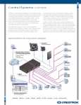
As shown below, each key on the keyboard is assigned a "Find" number that
corresponds to the Make and Break scan codes.
The following table lists the scan codes that apply to each key. For example, the "S"
key corresponds to the number 32. Thus, the Make scan code for this key is \x1B
and the Break scan code is \xF0\x1B.
14 • Crestron SIMPL™ Windows®
Symbol Guide – DOC. 6120
Crestron SIMPL™ Windows®
Software
See also CNWM on page 88, Mouse Simulator
Symbol Guide – DOC. 6120
Crestron SIMPL™ Windows® • 15
Crestron SIMPL™ Windows®
Software
CNSC-1A
Signals
•
Five digital inputs: <pwr>, <fwd>, <rev>, <foc+> and <foc->
•
Six digital outputs: <i1> through <i5> and <(AC) i6>
Description
The CNSC-1A is a slide projector interface. The <pwr> input sends main power to
the projector, while the <fwd> and <rev> inputs advance and reverse the projector's
slide mechanism. The two <foc> inputs adjust the focus settings.
The CNSC-1A also accepts five input closures. The <(AC) i6> input goes high
whenever the AC OUT switch on the front of the unit is pressed.
CNTV
Signals
•
One serial input: <TX$>
•
One serial output: <RX$>
Description
The CNTV is used in SchoolNet or stand-alone applications to control TVs and
other devices. The serial protocol that the CNTV requires differs depending on the
application. This protocol must be custom-programmed into the firmware by
Crestron.
ST-COM
The ST-COM provides two serial COM ports (A and B) that enable RS-232, RS424, and RS-485 communication.
Each port has a built-in serial driver with communication settings that must be
specified in Configuration Manager. These settings define the protocol that a
controlled serial device expects, and include the speed of data transmission (baud
rate), error checking (parity), and the number of data bits and stop bits. In addition,
a device might require hardware or software handshaking, which controls the flow
of data between two devices. The exact protocol will be described in the
manufacturer's documentation.
The Crestron database includes numerous serial devices, with default logic and preconfigured communication settings, that are compatible with the ports on the STCOM. These devices are identified in Configuration Manager by a
icon.
Simply drag the serial device to one of the ports on the ST-COM and click Yes
when prompted to replace the built-in serial driver for that port. In most cases, the
default logic should be loaded as well.
The ST-COM symbol detail requires no programming.
To program a serial driver expand the ST-COM by clicking the plus sign in
Program View. Then drag the desired serial driver to Detail View.
See also Serial Drivers
16 • Crestron SIMPL™ Windows®
Symbol Guide – DOC. 6120
Crestron SIMPL™ Windows®
Software
ST-LT
ST-LT is an interface to Lutron's GRAFIK EYE™ system. It provides two serial
COM ports (A and B) with built-in serial drivers. Port A (Lutron Port) connects
directly into the Lutron Mux Link, whereas Port B (9600 Port) is an RS-232 port
(set to a baud rate of 9600) for interfacing to a PC running Lutron control software.
The ST-LT symbol detail requires no programming.
To program a serial driver expand the ST-COM by clicking the plus sign in
Program View. Then drag the desired serial driver to Detail View.
See also Serial Drivers
ST-IO
Signals
•
Eight digital inputs: <relay1> through <relay8>
•
Four digital outputs: <i1> through <i4>
Description
The ST-IO provides eight isolated relays for controlling low voltage contact closure
devices such as drapes, screens and lifts. It also provides four local digital outputs.
When a <relay> signal goes high, the corresponding relay closes for as long as the
signal remains high. When the signal goes low, the relay opens. If a signal is
undefined, the relay is open.
The four local <i> outputs can function in either closure or voltage mode. In closure
mode (the default setting), an <i> signal goes high whenever the interface detects
the presence of a switch or relay closure to ground. In voltage mode, the <i> signal
goes high when it detects the presence of an active voltage (voltages > 2.5V = logic
1, and voltages < 1.5V = logic low).
Cresnet Power Control Modules
CNECI-4A
Signals
•
Four digital inputs: <relay1> through <relay4>
•
Eight digital outputs: <i1> through <i8>
Description
The CNECI-4A is a wall-mounted interface for controlling low voltage contact
closure devices such as drapes, screens and lifts. It provides four isolate relays,
typically driven by a CT-3000 touchpanel, and eight local digital outputs.
When a <relay> signal goes high, the corresponding relay closes for as long as the
signal remains high. When the signal goes low, the relay opens. If a signal is
undefined, the relay is open.
The eight <i> outputs can function in either closure or voltage mode. In closure
mode (the default setting), an <i> signal goes high whenever the interface detects
the presence of a switch or relay closure to ground. In voltage mode, the <i> signal
goes high when it detects the presence of an active voltage (voltages > 2.5V = logic
1, and voltages < 1.5V = logic low).
Symbol Guide – DOC. 6120
Crestron SIMPL™ Windows® • 17
Crestron SIMPL™ Windows®
Software
ST-PC
Signals
•
Two digital inputs: <pwrA> and <pwrB>
•
Two digital outputs: <pressA> and <pressB>
Description
The ST-PC incorporates two independent AC sockets into one unit. The <pwr>
inputs supply power to a device; the <press> outputs go high whenever the
corresponding push button on the ST-PC is pressed.
Cresnet Sensing Modules
CNTS-N
Signal
•
One analog output: <temp>
Description
The CNTS-N detects and measures ambient room temperature. Typically, the
temperature reading is transmitted to a touchpanel via an Analog Scaler symbol.
The various gauge objects available in VT Pro-e can then display the value in a
number of formats.
ST-CS
Signals
•
Four digital outputs: <Full Sense 1>, <Full Sense 2>, <Partial Sense 1>
and <Partial Sense 2>
Description
The ST-CS incorporates two independent current sensors in one unit. The <Full
Sense> outputs go high whenever the average current drawn by a monitored device
exceeds the upper threshold that is specified for that device.
The <Partial Sense> outputs go high when the current drawn by the device exceeds
an intermediate threshold.
ST-VS
Signals
•
Digital outputs: <sense1> through <sense4>
Description
The ST-VS detects the presence of up to four discrete base band video signals.
Whenever a video signal is detected from a monitored device, such as a VCR or
television tuner, the corresponding <sense> output goes high. This signal can then
trigger a relay to lower a screen, for example, or turn lights on or off in a room.
18 • Crestron SIMPL™ Windows®
Symbol Guide – DOC. 6120
Crestron SIMPL™ Windows®
Software
Cresnet Video Modules
CNX-PVID8x3
Signals
•
3 levels of 8 analog inputs: <Src-For-Out-1-Level-N> through <Src-ForOut-8-Level-N>
•
3 levels of 16 digital outputs: <Sense-In-1-Level-N> through <Sense-In16-Level-N>
Description
The CNX-PVID8x3 is a video matrix switcher that selects video sources and
distributes the video to up to 8 outputs. It provides 3 levels, or tiers, of 16 RCA
inputs and 3 levels of 8 RCA outputs. It also provides 8 RJ45 connectors that enable
CAT5 cabling to Crestron's CNXRMC and CNXRMCLV room solution boxes.
The <Src-For-Out-M-Level-N> analogs select the video source for an output as
follows: the signal is set (typically via an Analog Initialize symbol) to a value that
corresponds to the video source. This value can range from 1-32, depending on the
hardware configuration. If a signal is set to 0, no video is sent. <Out-M> specifies
the output (1-8), while <Level-N> gives the level (1-3).
The following tables give the valid range of analog values for three different
hardware configurations.
Standard Configuration (maximum 16 sources)
Level
Allowable range of analog values
1
0 - 16
2
0 - 16
3
0 - 16
J13 Configuration (Levels 1 and 3 are jumpered together - maximum 32 sources)
Level
Allowable range of analog values
1
0 - 32 (17-32 represent inputs on Level 3)
2
0 - 16
3
unused
J13S Configuration (Level 3 is split - maximum 24 sources)
Level
Allowable range of analog values
1
0 - 24 (17-24 represent inputs on Level 3)
2
0 - 16
3
0, 9 - 16
Example 1 (Standard Configuration): A component video source is connected to
input 3 (Levels 1, 2, and 3). To distribute video to output 5, the following analogs
must be set to 3:
<Src-For-Out-5-Level-1> = 3
<Src-For-Out-5-Level-2> = 3
<Src-For-Out-5-Level-3> = 3
Symbol Guide – DOC. 6120
Crestron SIMPL™ Windows® • 19
Crestron SIMPL™ Windows®
Software
Example 2 (Standard Configuration): A composite video source is connected to
input 15 (Level 1). To distribute video to outputs 2, 5, and 7, the following analogs
must be set to 15:
<Src-For-Out-2-Level-1> = 15
<Src-For-Out-5-Level-1> = 15
<Src-For-Out-7-Level-1> = 15
Example 3 (Standard Configuration): An S video source is connected to input 12
(Levels 1 and 2). To distribute video to outputs 1 and 4, the following analogs must
be set to 12:
<Src-For-Out-1-Level-1> = 12
<Src-For-Out-1-Level-2> = 12
<Src-For-Out-4-Level-1> = 12
<Src-For-Out-4-Level-2> = 12
Example 4 (J13 Configuration): A composite video source is connected to input
27. To distribute video to outputs 2 and 3, the following analogs must be set to 27
(16 + 11):
<Src-For-Out-2-Level-1> = 27
<Src-For-Out-3-Level-1> = 27
The CNX-PVID provides 16 built-in video sensors that can be used for
synchronization or diagnostics. The <Sense-In> outputs will go high whenever the
presence of a video signal is detected at the corresponding input and level.
CNXPVID8x4
Signals
•
4 levels of 8 analog inputs: <Src-For-Out-1-Level-N> through <Src-ForOut-8-Level-N>
•
4 levels of 16 digital outputs: <Sense-In-1-Level-N> through <Sense-In16-Level-N>
Description
The CNX-PVID8x4 is a video matrix switcher that selects video sources and
distributes the video to up to 8 outputs. It provides all the functionality of the CNXPVID8x3, with the additional capability of distributing digital audio.
The CNX-PVID8x4 provides 4 levels, or tiers, of 16 RCA inputs and 4 levels of 8
RCA outputs. It also provides 8 RJ45 connectors that enable CAT5 cabling to
Crestron's CNXRMC and CNXRMCLV room solution boxes.
The <Src-For-Out-M-Level-N> analogs select the video source for an output as
follows: the signal is set (typically via an Analog Initialize symbol) to a value that
corresponds to the video source. This value can range from 1-32, depending on the
hardware configuration. If a signal is set to 0, no video is sent. <Out-M> specifies
the output (1-8), while <Level-N> gives the level (1-4).
The following tables give the valid range of analog values for three different
hardware configurations.
20 • Crestron SIMPL™ Windows®
Symbol Guide – DOC. 6120
Crestron SIMPL™ Windows®
Software
Standard Configuration (maximum 16 sources)
Level
Allowable range of analog values
1
2
3
4
0 - 16
0 - 16
0 - 16
0 - 16
J13 Configuration (Levels 1 and 3 are jumpered together - maximum 32 sources)
Level
Allowable range of analog values
1
0 - 32 (17-32 represent inputs on Level 3)
2
0 - 16
3
unused
4
0 - 16
J13S Configuration (Level 3 is split - maximum 24 sources)
Level
Allowable range of analog values
1
0 - 24 (17-24 represent inputs on Level 3)
2
0 - 16
3
0, 9 - 16
4
0 - 16
Example 1 (Standard Configuration): A component video source with digital
audio is connected to input 3 (Levels 1, 2, 3 and 4). To distribute video and digital
audio to output 5, the following analogs must be set to 3:
<Src-For-Out-5-Level-1> = 3
<Src-For-Out-5-Level-2> = 3
<Src-For-Out-5-Level-3> = 3
<Src-For-Out-5-Level-4> = 3
Example 2 (Standard Configuration): A composite video source with no digital
audio is connected to input 15 (Level 1). To distribute video to output 2, the
following analogs must be set to 15:
<Src-For-Out-2-Level-1> = 15
Example 3 (Standard Configuration): An S video source with digital audio is
connected to input 12 (Levels 1, 2 and 4). To distribute video and digital audio to
output 1, the following analogs must be set to 12:
<Src-For-Out-1-Level-1> = 12
<Src-For-Out-1-Level-2> = 12
<Src-For-Out-1-Level-4> = 12
Example 4 (J13 Configuration): A composite video source with digital audio is
connected to input 27. To distribute video and digital audio to output 3, the
following analogs must be set to the corresponding values:
<Src-For-Out-3-Level-1> = 27
<Src-For-Out-2-Level-4> = 11
The CNX-PVID provides 16 built-in video sensors that can be used for
synchronization or diagnostics. The <Sense-In> outputs will go high whenever the
presence of a video signal is detected at the corresponding input and level.
Symbol Guide – DOC. 6120
Crestron SIMPL™ Windows® • 21
Crestron SIMPL™ Windows®
Software
CNX-RMC
The CNX-RMC room solution box is typically used in video distribution
applications with the CNX-PVID8. The CNX-RMC receives video and digital
audio via CAT5 cabling and then distributes these inputs to local outputs. It also
provides a current sensor, 4 infrared (IR) ports and 1 RS-232 port for controlling
local devices.
The CNX-RMC symbol detail requires no programming.
To program a control card or device driver, expand the CNX-RMC by clicking the
plus sign in Program Manager, then drag the device to Detail View.
CNX-RMCLV
The CNX-RMCLV room solution box contains an 8x8 video matrix switcher, and is
typically used with the CNX-PVID8 in video distribution applications.
The CNX-RMCLV receives video and digital audio from the CNX-PVID8 via
CAT5 cabling. It can also receive analog audio via CAT5 from a CNX-BIPAD8.
And it can receive video/digital audio and analog audio from local sources via
standard RCA connections. The built-in Audio/Video Matrix Control module
distributes these inputs to local outputs.
The CNX-RMCLV also provides 4 current sensors, 4 infrared (IR) ports and 1 RS232 port for controlling local devices. Finally, it provides outputs for directing
video and digital audio back to the head end.
The CNX-RMCLV symbol detail requires no programming.
To program a control card or device driver, expand the CNX-RMCLV by clicking
the plus sign in Program Manager, then drag the device to Detail View.
CNXVGA
Description
The CNXVGA enables the display of RGB video on Crestron VT-3500(L)
touchpanels.
The CNXVGA accepts RGB video in most standard formats (VGA, SVGA, MAC,
etc.) and outputs either composite or S video.
Signals
•
Digital inputs: <RGB>, <Video> and <out_disable>
•
Digital outputs: <RGB_on>, <Video_on>
The <RGB> and <Video> inputs select the video format of the source, on the rising
edge of the signal, with the <on> outputs providing the corresponding feedback.
The <out_disable> signal cuts off the video output for as long as the signal is high.
•
Digital inputs: <in_adj> and <out_adj>
•
Digital inputs: <up>, <down>, <left>, <right>, <width+>, <width->,
<height+>, <height-> and <save_settings>
•
Digital inputs: <in_recenter> and <out_recenter>
The <in_adj> input enables the user to position and size the RGB image on the
touch screen. The <out_adj> input is used to define the viewing area for
applications where the target device is not a VT-3500(L) touchpanel. When either
of these inputs is high, the positional inputs (<up>, <down>, <left>, <right>,
22 • Crestron SIMPL™ Windows®
Symbol Guide – DOC. 6120
Crestron SIMPL™ Windows®
Software
<width> and <height>) will adjust the display in single steps with each rising edge
of the input.
Once the desired dimensions are obtained, a rising edge of the <save_settings>
input will store the parameters into a preset memory location. (This location is
specified by the <preset#> output, discussed later.)
During adjustment of the dimensions, the <in_recenter> input re-synchronizes the
CNXVGA with the input signal, should the image move out of the viewing area.
The input triggers a "best guess" adjustment based on the detected incoming signal.
The <out_recenter> input simply restores the <out_adj> factory settings for the
VT-3500.
•
Digital input: <autodetect_off>
By default, the CNXVGA is set to auto detect all incoming signals. In the case of a
stand-alone application this is needed to sense the incoming signal and adjust to its
parameters on the fly. If an application requires discrete preset selections, the
<autodetect_off> input should be set to 1.
•
Digital inputs: <preset_1> through <preset_25>, and <clear_preset>
•
Digital output: <preset_empty>
To use discrete preset selections, the <autodetect_off> input must be low. The
<clear_preset> input can be used to erase all of the settings in the selected preset
memory. The <preset_empty> output goes high whenever the presets have been
cleared.
•
Analog outputs: <preset#>, <vfreq> and <hfreq>
The <preset#> output gives the value of the currently selected preset memory
location, while the <freq> outputs report the values of the current horizontal and
vertical input frequencies.
Cresnet Remote Processing
CN-TVAV
The CN-TVAV controls devices such as TVs, VCRs, DVD players, and switchers
in one of three processing modes: local, remote, or mixed.
In local processing mode, the CN-TVAV operates as an independent control system,
uploaded with a SIMPL Windows logic program to control network devices.
In remote processing mode, the CN-TVAV operates in a master/slave arrangement
whereby the unit is controlled by another control system, typically a CNMSX-Pro.
Here the CN-TVAV is a peripheral device within the program of the host control
system. Thus all the functionality of the unit is accessed via the host control system,
with no programming in the CN-TVAV itself. Remote processing makes five slots
available on the CN-TVAV.
Mixed processing mode, as the name suggests, combines local processing and
remote processing. That is, some functionality is programmed into the unit whereas
other commands come from a host control system. For example, the Versiports
might be used to control equipment via the program in the CN-TVAV, while the IR
Port might be accessed by the host control system (with no IR driver in the CNTVAV). Mixed processing makes three slots available on the CN-TVAV.
The CN-TVAV symbol detail requires no programming.
To program a built-in card or device driver expand the CN-TVAV by clicking the
plus sign in Program View. Then drag the device to Detail View.
Symbol Guide – DOC. 6120
Crestron SIMPL™ Windows® • 23
Crestron SIMPL™ Windows®
Software
CN-ISC
Signals
•
Digital inputs: <dig-o1> through <dig-o999>
•
Analog inputs: <an_o1> through <an_o254>
•
Serial inputs: <serial-o1> through <serial-o127>
•
Digital outputs: <dig-i1> through <dig-i999>
•
Analog outputs: <an_i1> through <an_i254>
•
Serial outputs: <serial-i1> through <serial-i127>
Description
The CN-ISC symbol is an Intersystem Communications (ISC) symbol that enables
communication between a CN-TVAV and another control system.
Processing Modes
The CN-TVAV controls devices such as TVs, VCRs, DVD players, and switchers
in one of three processing modes: local, remote, or mixed. The CN-ISC symbol is
available when the CN-TVAV operates in either local or mixed processing mode; it
is not needed when the unit operates in remote processing mode.
In local processing mode, the CN-TVAV operates as an independent control
system, uploaded with a SIMPL Windows logic program to control network
devices. Depending on the application, the CN-TVAV may or may not have to
communicate with another control system. If it does need to communicate with
another control system, then 16 discrete symbols (channels) are available on slot 05
of the unit.
In remote processing mode, the CN-TVAV operates in a master/slave arrangement
whereby the unit is controlled by another control system, typically a CNMSX-Pro.
Here the CN-TVAV is a peripheral device within the program of the host control
system. Thus all the functionality of the unit is accessed via the host control system,
with no programming in the CN-TVAV itself. As described previously, the CN-ISC
symbol is not needed in remote processing mode, since in this instance the CENTVAV is simply another controlled network device.
Mixed processing mode, as the name suggests, combines local processing and
remote processing. That is, some functionality is programmed into the unit whereas
other commands come from a host control system. For example, the Versiports
might be used to control equipment via the program in the CN-TVAV, while the IR
Port might be accessed by the host control system (with no IR driver in the CNTVAV). In these applications, the host must communicate with the CN-TVAV via
the CN-ISC symbol that is built into slot 05 of the device. The 16 channels will be
visible in Program Manager.
Symbol Description
An ISC symbol can have practically any number and combination of digital, analog,
and serial inputs and outputs. Whenever any of its inputs changes value, the symbol
transmits this information across the network. On the receiving end, the data comes
into a second ISC symbol, which drives its outputs to the corresponding values.
The inputs of an ISC symbol are mapped to the outputs of another ISC symbol as
follows: all signals are internally numbered by position, starting at 0. Thus the index
of the first defined signal is 0, the index of the second is 1, the third, 2, and so forth.
Since signals are mapped by index, it is not necessary for input/output "pairs" to
24 • Crestron SIMPL™ Windows®
Symbol Guide – DOC. 6120
Crestron SIMPL™ Windows®
Software
have the same signal name. That is, an input signal at index 25 will always be
mapped to an output signal at index 25, regardless of what the signal names are.
See also Intersystem, Ethernet Intersystem Communication on page 35, Virtual
Communication Port on page 41
TVAVIO
The TVAVIO is built into the CN-TVAV and CEN-TVAV. It provides a power
sensor and four Versiports, each of which can function as a digital input, digital
output or analog input. Each Versiport has a corresponding pull-up resistor.
Signals
•
Power Sensor: <PowerSense>
Versiports
Digital output mode
•
Digitals: <o1> through <o4>
Digital input mode
•
Digitals: <i1> through <i4>
Analog input mode
•
Analogs: <i1> through <i4>
•
One parameter: <backlash>
All Versiport modes
•
For each Versiport, one corresponding pull-up resistor: <pu-disable1>
through <pu-disable4>
Description
The following diagram shows the internal configuration of a Versiport.
+5V
2K
pullup1
S1-A
VersiPort 1
o1
S1-B
A
Used for analog input.
Can be either a voltage
source or resistive load.
Digital Output Mode
When a Versiport is operating in digital output mode, the output pin will be shorted
to ground on the rising edge of the corresponding <o> signal (switch S1-B in the
above diagram will be closed). When <o> goes low, the output pin is driven to a
value of +5V (switch S1-B is open).
This behavior can be modified by driving the corresponding <pu-disable> signal
high, although this is not recommended since it will cause the output pin to float
when <o> goes low.
Symbol Guide – DOC. 6120
Crestron SIMPL™ Windows® • 25
Crestron SIMPL™ Windows®
Software
Example 1 (recommended): <pu-disable1> is driven low or left undefined. When
<o1> goes low, Versiport 1 is at +5V. When <o1> goes high, Versiport 1 is shorted
to ground.
Example 2 (not recommended): <pu-disable1> is driven high. When <o1> goes
low, Versiport 1 is floating. When <o1> goes high, Versiport 1 is shorted to ground.
Digital Input Mode
When a Versiport is operating in digital input mode, the corresponding <i> signal
will go high whenever the TVAVIO detects that the Versiport is shorted to ground
(threshold < +2.5V). Note that here, as with digital output mode, the corresponding
pull-up resistor should be enabled. That is, <pu-disable> should be given the signal
name 0 or left undefined; otherwise the input will always read as logic low.
Example: When Versiport 3 is shorted to ground, <i3> will go high. When
Versiport 3 is not shorted to ground, <i3> will go low (so long as <pu-disable3>
equals 0 or is undefined).
Analog Input Mode
In analog input mode, the Versiport is typically tied to a resistive load (such as a
humidity sensor) or a voltage source (both can be represented by box "A" in the
diagram).
When a resistive load is tied to a Versiport, the corresponding pull-up resistor must
be enabled (again, this means that <pu-disable> should be given the signal name 0
or left undefined). This creates a voltage divider and provides a varying voltage
level (based on the current resistance of the sensor) for the TVAVIO to read.
Example: A resistive humidity sensor is tied to Versiport 1 (and <pu-disable1> is
low or undefined). <ain1> will assume the corresponding analog value.
When a voltage source is tied to a Versiport, the corresponding pull-up resistor
should be disabled (the only case where the default setting should be overridden).
This allows the TVAVIO to read the value of the voltage source directly.
Example: A voltage source is tied to Versiport 1 and <pu-disable1> is given the
signal name 1. <ain1> will assume the corresponding analog value (ranging from 0
to 65535, or 0 to +10V on the input pin).
The TVAVIO does not propagate all changes in the analog values of its Versiports,
since this can lead to undesirable results if the input source is not clean or has jitter.
Rather, the <backlash> parameter specifies a hysteresis value, such that if the
current level changes direction, the new value will not be reported until it changes
by <backlash>. (If no <backlash> parameter is specified the default value is 1%.)
Example: A voltage source is placed on Versiport 1 and <backlash> equals 1%.
The input voltage drops to 4.0 volts from some higher voltage. <i1> will assume a
value of 4. If the voltage should then rise, the value of <i1> will not change until
the voltage level reaches 4.1 volts.
26 • Crestron SIMPL™ Windows®
Symbol Guide – DOC. 6120
Crestron SIMPL™ Windows®
Software
AV2 Remote Processing
The AV2, like all 2-Series control systems, operates in one of two processing
modes: local or remote.
In local processing mode, the AV2 operates as an independent control system,
uploaded with a SIMPL Windows logic program to control network devices.
In remote processing mode, the AV2 operates in a master/slave arrangement
whereby the unit is controlled by another control system such as a PRO2. Here the
AV2 is a peripheral device within the program of the host control system. Thus all
the functionality of the unit is accessed via the host control system, with no
programming in the AV2 itself. Remote processing makes three slots available on
the AV2.
The AV2 symbol detail requires no programming.
To program a built-in card or device driver, expand the AV2 by clicking the plus
sign in Program View. Then drag the device from a slot to Detail View.
CP2 Remote Processing
The CP2, like all 2-Series control systems, operates in one of two processing
modes: local or remote.
In local processing mode, the CP2 operates as an independent control system,
uploaded with a SIMPL Windows logic program to control network devices.
In remote processing mode, the CP2 operates in a master/slave arrangement
whereby the unit is controlled by another control system such as a PRO2. Here the
CP22 is a peripheral device within the program of the host control system. Thus all
the functionality of the unit is accessed via the host control system, with no
programming in the CP22 itself. Remote processing makes three slots available on
the CP2.
The CP2 symbol detail requires no programming.
To program a built-in card or device driver, expand the CP2 by clicking the plus
sign in Program View. Then drag the device from a slot to Detail View.
CNX-DVP4
The CNX-DVP4, like all 2-Series control systems, operates in one of two
processing modes: local or remote.
In local processing mode, the DVP4 operates as an independent control system,
uploaded with a SIMPL Windows logic program to control network devices.
In remote processing mode, the DVP4 operates in a master/slave arrangement
whereby the unit is controlled by another control system such as a PRO2. Here the
DVP4 is a peripheral device within the program of the host control system. Thus all
the functionality of the unit is accessed via the host control system, with no
programming in the DVP4 itself. Remote processing makes two slots available on
the DVP4.
The DVP4 symbol detail requires no programming.
To program a built-in card or device driver, expand the DVP4 by clicking the plus
sign in Program View. Then drag the device from a slot to Detail View.
Symbol Guide – DOC. 6120
Crestron SIMPL™ Windows® • 27
Crestron SIMPL™ Windows®
Software
PAC2 Remote Processing
The PAC2, like all 2-Series control systems, operates in one of two processing
modes: local or remote.
In local processing mode, the PAC2 operates as an independent control system,
uploaded with a SIMPL Windows logic program to control network devices.
In remote processing mode, the PAC2 operates in a master/slave arrangement
whereby the unit is controlled by another control system such as a PRO2. Here the
PAC2 is a peripheral device within the program of the host control system. Thus all
the functionality of the unit is accessed via the host control system, with no
programming in the PAC2 itself. Remote processing makes three slots available on
the PAC2.
The PAC2 symbol detail requires no programming.
To program a built-in card or device driver, expand the PAC2 by clicking the plus
sign in Program View. Then drag the device from a slot to Detail View.
PRO2 Remote Processing
The PRO2, like all 2-Series control systems, operates in one of two processing
modes: local or remote.
In local processing mode, the PRO2 operates as an independent control system,
uploaded with a SIMPL Windows logic program to control network devices.
In remote processing mode, the PRO2 operates in a master/slave arrangement
whereby the unit is controlled by a control system such as another PRO2. Here the
PRO2 is a peripheral device within the program of the host control system. Thus all
the functionality of the unit is accessed via the host control system, with no
programming in the PRO2 itself. Remote processing makes three slots available on
the PRO2.
The PRO2 symbol detail requires no programming.
To program a built-in card or device driver, expand the PRO2 by clicking the plus
sign in Program View. Then drag the device from a slot to Detail View.
RACK2 Remote Processing
The RACK2, like all 2-Series control systems, operates in one of two processing
modes: local or remote.
In local processing mode, the RACK2 operates as an independent control system,
uploaded with a SIMPL Windows logic program to control network devices.
In remote processing mode, the RACK2 operates in a master/slave arrangement
whereby the unit is controlled by another control system such as a PRO2. Here the
RACK2 is a peripheral device within the program of the host control system. Thus
all the functionality of the unit is accessed via the host control system, with no
programming in the RACK2 itself. Remote processing makes three slots available
on the RACK2.
The RACK2 symbol detail requires no programming.
To program a built-in card or device driver, expand the RACK2 by clicking the plus
sign in Program View. Then drag the device from a slot to Detail View.
28 • Crestron SIMPL™ Windows®
Symbol Guide – DOC. 6120
Crestron SIMPL™ Windows®
Software
Ethernet Control Modules
Ethernet Modules (Crestron)
CEN-CN
The CEN-CN provides two Cresnet ports (represented by slot 05) that enable
communication with all Cresnet devices, and one LAN port that connects to the
control system via Ethernet. In this way, the CEN-CN provides Ethernet
connectivity between local Cresnet devices and a remotely located control system.
The CEN-CN symbol detail requires no programming.
To program a Cresnet device, expand the CEN-CN by clicking the plus sign in
Program View. Then expand the Remote Cresnet Device symbol, which also
requires no programming, and drag the device to Detail View.
CEN-COM
The CEN-COM provides two serial COM ports (A and B) that enable RS-232 or
RS-422 communication, and one LAN port that connects to the control system via
Ethernet.
Each COM port has a built-in serial driver with communication settings that must
be specified in Configuration Manager. These settings define the protocol that a
controlled serial device expects, and include the speed of data transmission (baud
rate), error checking (parity), and the number of data bits and stop bits. In addition,
a device might require hardware or software handshaking, which controls the flow
of data between two devices. The exact protocol will be described in the
manufacturer's documentation.
The Crestron database includes numerous serial devices, with default logic and preconfigured communication settings that are compatible with the ports on the COM
icon. Simply
card. These devices are identified in Configuration Manager by a
drag the serial device to one of the ports on the COM card and click Yes when
prompted to replace the built-in serial driver for that port. If desired, the default
logic can be loaded as well.
The CEN-COM symbol detail requires no programming.
To program a serial driver expand the CEN-COM by clicking the plus sign in
Program View. Then drag the desired serial driver to Detail View.
See also Serial Drivers
CEN-IO
The CEN-IO provides eight relays and eight Versiports. Each Versiport has a
corresponding pull-up resistor, and can function as a digital input, a digital output or
an analog input.
Relays
Symbol Guide – DOC. 6120
•
Eight relays: <relay1> through <relay8>
•
For each relay, one corresponding feedback signal: <relay1-f> through
<relay8-f>
Crestron SIMPL™ Windows® • 29
Crestron SIMPL™ Windows®
Software
Versiports
Digital output mode
•
Digitals: <o1> through <o8>
•
For each digital, one corresponding feedback signal: <o1-f> through <o8f>
Digital input mode
•
Digitals: <i1> through <i8>
Analog input mode
•
Analogs: <ain1> through <ain8>
•
For each analog, one corresponding minimum change value:
<MinChange1> through <MinChange8>
•
For each minimum change value, one corresponding feedback signal:
<MinChange1-f> through <MinChange8-f>
All Versiport modes
•
For each Versiport, one corresponding pull-up resistor: <pullup1-dis>
through <pullup8-dis>
•
For each resistor, one corresponding feedback signal: <pullup1-dis-f>
through <pullup8-dis-f>
Description
The CEN-IO provides 8 isolated relays for controlling low-voltage contact closure
devices such as drapes, screens and lifts.
When a <relay> signal goes high, the corresponding relay closes for as long as the
signal remains high. When the signal goes low, the relay opens. If a signal is
undefined, the relay is open.
The following diagram shows the internal configuration of a Versiport.
+5V
2K
pullup1
S1-A
VersiPort 1
o1
S1-B
A
Used for analog input.
Can be either a voltage
source or resistive load.
Digital Output Mode
When a Versiport is operating in digital output mode, the output pin will be shorted
to ground on the rising edge of the corresponding <o> signal (switch S1-B in the
above diagram will be closed). When <o> goes low, the output pin is driven to a
value of +5V (switch S1-B is open).
30 • Crestron SIMPL™ Windows®
Symbol Guide – DOC. 6120
Crestron SIMPL™ Windows®
Software
This behavior can be modified by driving the corresponding <pullup1-dis> signal
high, although this is not recommended since it will cause the output pin to float
when <o> goes low.
Example 1 (recommended): <pullup1-dis> is driven low or left undefined. When
<o1> goes low, Versiport 1 is at +5V. When <o1> goes high, Versiport 1 is shorted
to ground.
Example 2 (not recommended): <pullup1-dis> is driven high. When <o1> goes
low, Versiport 1 is floating. When <o1> goes high, Versiport 1 is shorted to ground.
Each signal <o1> through <o8> has corresponding feedback <o1-f> through <o8-f>
that is driven by the CEN-IO. Feedback is provided because the CEN-IO can accept
commands from multiple control systems.
Digital Input Mode
When a Versiport is operating in digital input mode, the corresponding <i> signal
will go high whenever the CEN-IO detects that the Versiport is shorted to ground
(threshold < +2.5V). Note that here, as with digital output mode, the corresponding
pull-up resistor should be enabled. That is, <pullup-dis> should be given the signal
name 0 or left undefined; otherwise the input will always read as logic low.
Example: When Versiport 3 is shorted to ground, <i3> will go high. When
Versiport 3 is not shorted to ground, <i3> will go low (so long as <pullup3-dis>
equals 0 or is undefined).
Analog Input Mode
In analog input mode, the Versiport is typically tied to a resistive load (such as a
humidity sensor) or a voltage source (both can be represented by box "A" in the
diagram).
When a resistive load is tied to a Versiport, the corresponding pull-up resistor must
be enabled (again, this means that <pu-disable> should be given the signal name 0
or left undefined). This creates a voltage divider and provides a varying voltage
level (based on the current resistance of the sensor) for the CEN-IO to read.
Example: A resistive humidity sensor is tied to Versiport 1 (and <pu-disable1> is
low or undefined). <ain1> will assume the corresponding analog value.
When a voltage source is tied to a Versiport, the corresponding pull-up resistor
should be disabled (the only case where the default setting should be overridden).
This allows the CEN-IO to read the value of the voltage source directly.
Example: A voltage source is tied to Versiport 1 and <pu-disable1> is given the
signal name 1. <ain1> will assume the corresponding analog value (ranging from 0
to 65535, or 0 to +10V on the input pin).
The CEN-IO does not propagate all changes in the analog values of its Versiports,
since this can lead to undesirable results if the input source is not clean or has jitter.
Rather, the <MinChange> signals should be used to specify a "minimum change"
value. This means that the CEN-IO will not propagate the new value until it
changes by <MinChange>.
Example: A voltage source is placed on Versiport 1 and <MinChange1> is set to
10 via an Analog Initialize symbol. The value of <ain1> will not be propagated
until it changes by at least 10. If the current value is 500, then a new value will not
be reported until it changes to 510 or 490.
Each signal <MinChange1> through <MinChange8> has corresponding feedback
<MinChange1-f> through <MinChange8-f> that is driven by the CEN-IO.
Feedback is provided because the CEN-IO can accept commands from multiple
control systems.
Symbol Guide – DOC. 6120
Crestron SIMPL™ Windows® • 31
Crestron SIMPL™ Windows®
Software
CEN-ISC (16 Channels)
Signals
•
Digital inputs: <dig-o1> through <dig-o999>
•
Analog inputs: <an_o1> through <an_o254>
•
Serial inputs: <serial-o1> through <serial-o127>
•
Digital outputs: <dig-i1> through <dig-i999>
•
Analog outputs: <an_i1> through <an_i254>
•
Serial outputs: <serial-i1> through <serial-i127>
Description
The CEN-ISC symbol is an Ethernet Intersystem Communications (ISC) symbol
that enables Ethernet communication between a CEN-TVAV and another control
system.
Processing Modes
The CEN-TVAV controls devices such as TVs, VCRs, DVD players, and switchers
in one of three processing modes: local, remote, or mixed. The CEN-ISC symbol is
available when the CEN-TVAV operates in either local or mixed processing mode;
it is not needed when the unit operates in remote processing mode.
In local processing mode, the CEN-TVAV operates as an independent control
system, uploaded with a SIMPL Windows logic program to control network
devices. Depending on the application, the CEN-TVAV may or may not have to
communicate with another control system. If it does need to communicate with
another control system, then the CEN-ISC(L) symbol, located in the Ethernet
Control Modules folder of Configuration Manager, must be dragged to slot 07 of
the CEN-TVAV. This will make 16 discrete symbols (channels) available for
programming.
In remote processing mode, the CEN-TVAV operates in a master/slave arrangement
whereby the unit is controlled by another control system, typically a CNMSX-Pro.
Here the CEN-TVAV is a peripheral device within the program of the host control
system. Thus all the functionality of the unit is accessed via the host control system,
with no programming in the CEN-TVAV itself. As described previously, the CENISC symbol is not needed in remote processing mode, since in this instance the
CEN-TVAV is simply another controlled network device.
Mixed processing mode, as the name suggests, combines local processing and
remote processing. That is, some functionality is programmed into the unit whereas
other commands come from a host control system. For example, the Versiports
might be used to control equipment via the program in the CEN-TVAV, while the
IR Port might be accessed by the host control system (with no IR driver in the
CEN-TVAV). In these applications the host must communicate with the CENTVAV via the CEN-ISC(R) symbol that is built into slot 07 of the device. The 16
channels will be visible in Program Manager.
Symbol Description
An Ethernet ISC symbol can have practically any number and combination of
digital, analog, and serial inputs and outputs. Whenever any of its inputs changes
value, the symbol encodes this information into a packet and transmits the packet
via Ethernet. On the receiving end, the packet comes into a second Ethernet ISC
symbol, which decodes the data and drives its outputs to the corresponding values.
32 • Crestron SIMPL™ Windows®
Symbol Guide – DOC. 6120
Crestron SIMPL™ Windows®
Software
The inputs of an Ethernet ISC symbol are mapped to the outputs of another Ethernet
ISC symbol as follows: all signals are internally numbered by position, starting at 0.
Thus the index of the first defined signal is 0, the index of the second is 1, the third,
2, and so forth. Since signals are mapped by index, it is not necessary for
input/output "pairs" to have the same signal name. That is, an input signal at index
25 will always be mapped to an output signal at index 25, regardless of what the
signal names are.
See also Intersystem Communications, Ethernet Intersystem Communication on
page 35, Virtual Communication Port on page 41
CEN-OEM (e-Server)
Signals
•
Digital inputs: <dig-o1> through <dig-o999>
•
Analog inputs: <an_o1> through <an_o254>
•
Serial inputs: <serial-i1> through <serial-i127>
•
Digital outputs: <dig-i1> through <dig-i999>
•
Analog outputs: <an_i1> through <an_i254>
•
Serial outputs: <serial-o1> through <serial-o127>
Description
The e-Server symbol enables Ethernet communication between the control system
and the Crestron CEN-OEM, a device that provides Ethernet capabilities to Cresnet
devices. As with the ActiveCNX Interface and e-control PC Interface symbols, the
control system does not differentiate between this symbol and a touchpanel symbol.
Thus the signals on the output side of the symbol can be mapped to device
commands that have been programmed into the CEN-OEM unit, with the signals on
the input side providing the corresponding feedback.
TPS Cresnet Interface
TPS Ethernet Interface
TPS RS-232 Interface
Signals
•
Digital inputs: <fb1> through <fb4000>
•
Digital outputs: <press1> through <press4000>
•
Analog inputs: <an_fb1> through <an_fb4000>
•
Analog outputs: <an_act1> through <an_act4000>
•
Serial inputs: <text-o1> through <text-o999>
•
Serial outputs: <text-i1> through <text-i127>
Description
The TPS Cresnet/RS-232/Ethernet Interface symbols enable direct program access
to Crestron's entire bank of join numbers for TPS touchpanels. These join numbers
include the "standard" or general purpose join numbers 1 through 15999, as well as
all reserved join numbers, which begin at 17000.
Symbol Guide – DOC. 6120
Crestron SIMPL™ Windows® • 33
Crestron SIMPL™ Windows®
Software
Reserved join numbers trigger pre-defined functions that are specific (local) to a
touchpanel. For example, reserved join number 17203 corresponds to a panel's self
test function; when a button with that join number is pressed, the panel performs a
self test.
Previously, reserved join numbers have been accessible only when assigning a
button's properties in VT Pro-e, while the general purpose join numbers above 4000
have not been available at all in standard programming.
The TPS Interface symbol detail looks like a regular touchpanel symbol. It can
access join numbers through a mechanism called Join Number Remapping (JNR),
which brings join numbers with very high values to within the range of a standard
touchpanel symbol; or in this case, the TPS Interface symbol. Through JNR, one
touchpanel can activate the local functions of other touchpanels, send device
commands (without logic) to control systems, and receive feedback from remote
locations. JNR provides the additional capability of managing IP IDs in Ethernet
applications where a touchpanel communicates with multiple control systems that
have been uploaded with the same program.
To use the JNR feature, a TPS touchpanel must be brought into SIMPL Windows as
the "control system" in Configuration Manager. This TPS control system provides
slots for TPS Screen Interface symbols that group join numbers according to
function. This is shown in the following table:
TPS
Slot
TPS Screen
Interface Symbol
Join Number Range (Function)
01
TPS_1-4000
1 - 4000 (Standard)
02
TPS_4001-8000
4001 - 8000 (Standard)
03
TPS_8001-12000
8001 - 12000 (Standard)
04
TPS_12001-15999
12001 - 15999 (Standard)
05
TPS_XGA_RES
17000 - 17041 (XGA Reserved)
06
TPS_VIDEO_RES
17100 - 17122 (Video Reserved)
07
TPS_SYSTEM_RES
17200 - 17287, 32768 - 32770 (System Reserved)
08
TPS_AUDIO_RES
17300 - 17324 (Audio Reserved)
09
TPS_ETHERNET_RES
17400 - 17402 (Ethernet Reserved)
10
TPS_RS-232_RES
17600 - 17623 (RS-232 Setup Reserved)
11
TPS_PRODUCT_RES
17700 - 17701 (Product Reserved)
12
TPS_TOUCHOUT_RES
17818 - 17835 (Mouse Reserved)
13
TPS_RF_RES
17500 - 17508 (RF Reserved)
The TPS "control system" also provides the three TPS Interface symbols described
here, corresponding to the three communication ports on the touchpanel:
34 • Crestron SIMPL™ Windows®
•
The TPS Cresnet Interface symbol, found in the Network Modules folder
in Program View, is used for Cresnet connections.
•
The TPS Ethernet Interface symbol (also called TPS Device for Ethernet
Panels), found in the Ethernet folder of the Device Library, is used for
Ethernet connections.
•
The TPS RS-232 Interface symbol is found in slot 20 of the TPS control
system and is used for RS-232. Note that the RS-232 port is not a
dedicated port. That is, it can be configured for various communication
modes. Thus is it necessary to set the port explicitly to Control Mode for
Symbol Guide – DOC. 6120
Crestron SIMPL™ Windows®
Software
use in RS-232 applications (go to the touchpanel Setup Menu, press RS232, then press RS-232 Port for Control).
The TPS Interface symbol works in combination with the Screen Interface symbols
described in the above table as follows:
1. The <press> outputs of the TPS Interface symbol are connected to the desired
inputs of the Screen Interface symbol.
2.
The outputs of the Screen Interface symbol can be connected to the <fb> inputs
of the TPS Interface symbol.
In this way, the TPS Interface differs from a standard touchpanel symbol, in that the
<fb> signals must not be tied to their corresponding <press> outputs.
Example 1: To enable the sound of a (remote) touchpanel key click via Cresnet,
connect a <pressN> output of the TPS Cresnet Interface symbol to the <Beep_On>
input of the Audio Reserved Joins symbol. Connect the <Beep_On_fb> output of
the Audio Reserved Joins symbol to the <fbN> input of the TPS Cresnet Interface
symbol.
Example 2: To control the self-test function of a (remote) touchpanel via Ethernet,
connect the <pressN> output on the TPS Ethernet Interface symbol to the
<Selftest> input of the System Reserved Joins symbol. Connect the
<Selftest_Running> output of the System Reserved Joins symbol to the <fbN>
input of the TPS Ethernet Interface symbol.
Example 3: To specify the level of brightness for (remote) touchpanel video via RS232, connect the <an_actN> output of the TPS RS-232 Interface symbol to the
<Brightness> input of the Video Reserved Joins symbol. (An Analog Initialize
symbol would be used to set the brightness level.) Connect the <Brightness_fb>
output of the Video Reserved Joins symbol to the <an_fbN> input of the TPS RS232 Interface symbol for a real-time reading of the current level.
Ethernet Intersystem Communication
Signals
•
Digital inputs: <dig-o1> through <dig-o999>
•
Analog inputs: <an_o1> through <an_o254>
•
Serial inputs: <serial-i1> through <serial-i127>
•
Digital outputs: <dig-i1> through <dig-i999>
•
Analog outputs: <an_i1> through <an_i254>
•
Serial outputs: <serial-o1> through <serial-o127>
Description
Intersystem Communication (ISC) symbols enable data to be passed back and forth
between two or more control systems. The original implementation of the ISC
symbol allows communication via a serial connection, such as modem or RS-422.
Crestron developed the Ethernet ISC symbol to enable communication via Ethernet
as well.
An Ethernet ISC symbol can have practically any number and combination of
digital, analog, and serial inputs and outputs. Whenever any of its inputs changes
value, the symbol encodes this information into a packet and transmits the packet
via Ethernet. On the receiving end, the packet comes into a second Ethernet ISC
symbol, which decodes the data and drives its outputs to the corresponding values.
Symbol Guide – DOC. 6120
Crestron SIMPL™ Windows® • 35
Crestron SIMPL™ Windows®
Software
The inputs of an Ethernet ISC symbol are mapped to the outputs of another Ethernet
ISC symbol as follows: all signals are internally numbered by position, starting at 0.
Thus the index of the first defined signal is 0, the index of the second is 1, the third,
2, and so forth. Since signals are mapped by index, it is not necessary for
input/output "pairs" to have the same signal name. That is, an input signal at index
25 will always be mapped to an output signal at index 25, regardless of what the
signal names are.
To ensure proper routing of the Ethernet packets from one control system to the
other, the IP IDs of both Ethernet ISC symbols must be the same. In addition, each
symbol must be assigned the IP address of the target control system. That is, in
System A, an Ethernet ISC symbol with IP ID 07 would be assigned the IP address
of System B. The Ethernet ISC symbol in System B would likewise have IP ID 07,
and be assigned the IP address of System A. Note that there can be as many
Ethernet ISC symbols in a control system as there are valid IP IDs (maximum of
251), and thus many communication channels can be established between control
systems.
Note: An alternative method for communicating via Ethernet between control
systems is to use the original ISC symbol in conjunction with a Virtual
Communication Port symbol. This method is recommended for applications that
require the use of initialization commands or <Offset> parameters.
See also Intersystem Communications, Virtual Communication Port on page 41
Ethernet Modules (Generic)
ActiveCNX Interface
Signals
•
Digital inputs: <dig-o1> through <dig-o999>
•
Analog inputs: <an_o1> through <an_o254>
•
Serial inputs: <serial-o1> through <serial-o127>
•
Digital outputs: <dig-i1> through <dig-i999>
•
Analog outputs: <an_i1> through <an_i254>
•
Serial outputs: <serial-i1> through <serial-i127>
Description
The ActiveCNX Interface symbol enables Ethernet communication between the
control system and a PC-based program running ActiveX controls. It is equivalent
to an e-Control PC Interface symbol, except that the latter symbol more typically
connects to a Web browser running Java applets. In this way, the PC becomes a
custom interface that can control network devices and display feedback. In fact, the
control system does not differentiate between these symbols and touchpanel
symbols.
The signals on the output side of the symbol correspond to events, such as key
presses, button clicks, or mouse movements, that generate a response from the
computer program, with the signals on the input side providing the corresponding
feedback.
NOTE: In applications that incorporate the CNX (software) Gateway, the
ActiveCNX Interface symbol must be assigned the IP address of that gateway. In
36 • Crestron SIMPL™ Windows®
Symbol Guide – DOC. 6120
Crestron SIMPL™ Windows®
Software
applications that use the hardware gateway that is built into the CNXENET+ card,
the IP address should explicitly be set to 0.0.0.0.
See also e-Control PC Interface on page 37, e-Server on page 33
e-Control PC Interface
Signals
•
Digital inputs: <fb1> through <fb999>
•
Digital outputs: <press1> through <press999>
•
Analog inputs: <an_fb1> through <an_fb254>
•
Analog outputs: <an_act1> through <an_act254>
•
Serial inputs: <text-o1> through <text-o127>
•
Serial outputs: <text-i1> through <text-i127>
Description
The e-Control PC Interface symbol enables Ethernet communication between the
control system and a PC, usually a Web browser running Java applets. It is
equivalent to an ActiveCNX Interface symbol, except that the latter symbol more
typically connects to a program running ActiveX controls. In this way, the Web
browser becomes a custom interface that can control network devices and display
feedback. In fact, the control system does not differentiate between these symbols
and touchpanel symbols.
The signals on the output side of the symbol correspond to events, such as key
presses, button clicks, or mouse movements, that generate a response from the
computer program, with the signals on the input side providing the corresponding
feedback.
NOTE: In applications that incorporate the CNX (software) Gateway, the PC
Interface symbol must be assigned the IP address of that gateway. In applications
that use the hardware gateway that is built into the CNXENET+ card, the IP address
should explicitly be set to 0.0.0.0.
See also ActiveCNX Interface on page 36, e-Server on page 33
e-Datalog Interface
Signal
•
One serial input: <DataToLog>
Description
The e-Datalog Interface symbol transmits strings from the control system to an eDatalog software program on a PC. The data is transmitted over Ethernet; each
string can be up to 255 characters long.
The <DataToLog> input is normally driven by the <tx$> output of a Serial I/O
symbol. In the serial output form, the Serial I/O symbol transmits a string whenever
that string's corresponding input signal goes high. For example, the Serial I/O symbol
can transmit the string "System_On" whenever the control system powers on.
The e-Datalog software provides 2 text fields for displaying the logging
information: the Event field, and the Details field. To write to both fields, use "||"
(two vertical line characters) as a delimiter between the two fields. The portion of
Symbol Guide – DOC. 6120
Crestron SIMPL™ Windows® • 37
Crestron SIMPL™ Windows®
Software
the string before the "||" will be recorded in the Event field. The portion after the "||"
will be recorded in the Details field. If the "||" delimiter is not used, the string will
be recorded in the Event field only.
For example, to write "Source Selection" and "VCR Selected" to the two fields, the
string should be formatted as follows: Source Selection||VCR Selected.
e-Outlook Interface
Signals
•
One digital input: <DataRequest>
•
Three digital outputs: <Init>, <DisplayStrings> and <ConnectionStatus>
•
Six serial outputs: <Times>, <Names>, <Actions>, <Descriptions>,
<Contacts> and <Categories>
Description
The e-Outlook Interface symbol connects the control system to a PC running
Crestron's e-Outlook software.
e-Outlook is an e-Control Power Application that extends the functionality of
Microsoft Outlook, allowing users to access their Outlook calendars and agendas
via Crestron touchpanels.
The e-Outlook Interface symbol works together with the User module, e-Outlook.umc,
which interprets the Microsoft Outlook commands. The e-Outlook module is added to
the User Modules directory when the e-Outlook package is installed.
All of the signals on the e-Outlook Interface symbol should be connected to the
corresponding signals on the e-Outlook module. For further information about the
module, select it and press F1.
e-PowerPoint Interface
The e-PowerPoint Interface symbol connects the control system to a PC running
Crestron's e-PowerPoint software.
The e-PowerPoint software package allows Crestron control systems and
touchpanels to start, control and run a Microsoft PowerPoint presentation that
resides on an Ethernet-accessible PC. Speaker's notes associated with individual
PowerPoint slides can be shown on Crestron touchpanels alongside presentation
control buttons.
The digital inputs of the e-PowerPoint Interface symbol should be connected to
button presses on the touchpanel displaying the PowerPoint presentation. The
outputs should be routed as feedback to the touchpanel.
38 • Crestron SIMPL™ Windows®
Symbol Guide – DOC. 6120
Crestron SIMPL™ Windows®
Signal
Digital input: <FirstSlide>
Digital input: <PreviousSlide>
Software
Description
Display the indicated slide (first, previous, next or last)
in the presentation, on the rising edge of the signal.
Digital input: <NextSlide>
Digital input: <LastSlide>
Digital input: <NotesPageFirst>
Digital input: <NotesPagePrevious>
Digital input: <NotesPageNext>
Display the indicated page (first, previous, next or last)
of speaker's notes, on the rising edge of the signal. The
number of lines to be displayed is given by the
<NotesPageLines> input.
Digital input: <NotesPageLast>
Digital input: <SlidesPageFirst>
Digital input:
<SlidesPagePrevious>
Digital input: <SlidesPageNext>
Display the indicated page (first, previous, next or last)
of slide names, on the rising edge of the signal. The
number of lines to be displayed is given by the
<SlidesPageLines> input.
Digital input: <SlidesPageLast>
Symbol Guide – DOC. 6120
Digital inputs: <Shortcut1> through
<Shortcut10>
Open the indicated pre-defined presentation on the
rising edge of the signal.
Digital input: <EndPresentation>
Stop the presentation. (To open a new presentation
select a shortcut or start the presentation from the PC.)
Digital input: <EndPowerpoint>
Close PowerPoint.
Digital inputs: <Slide1> through
<Slide10>
Display the indicated slide, as numbered on the
scrolling list of slide names.
Digital input: <SlideSelectEnter>
On the rising edge of this input, display the slide that is
specified by <SlideSelector>.
Analog input: <NotesPageLines>
Specifies the maximum number of lines of speaker's
notes to send to the control system for scrolling display.
Valid values range from 1 through 10.
Analog input: <NotesPageChars>
Specifies the maximum number of characters per line of
speaker's notes. Valid values range from 1 through 250.
Analog input: <SlidesPageLines>
Specifies the maximum number of lines of slide names
to send to the control system for scrolling display. Valid
values range from 1 through 10.
Analog input: <SlidesPageChars>
Specifies the maximum number of characters per slide
name. Valid values range from 1 through 50.
Analog input: <SlideSelector>
Specifies the number of the slide to be displayed on the
rising edge of <SlideSelectEnter>.
Analog output: <CurrentSlide>
Indicates the current slide number (as an analog value).
Analog output: <TotalSlides>
Indicates the total number of slides in the current
presentation (as an analog value).
Serial output: <PresentationName>
File name of the current presentation.
Serial output: <SlideName>
Name of the current slide.
Serial output: <Slide#>
Indicates the current slide number (as a string).
Serial output: <TotalSlides>
Indicates the total number of slides in the current
presentation (as a string).
Serial outputs: <NotesLine1>
through <NotesLine10>
The lines of speaker's notes that are displayed in the
scrolling list. The total number of lines shown at one
time is given by <NotesPageLines>, while the
maximum number of characters per line is given by
<NotesPageChars>.
Crestron SIMPL™ Windows® • 39
Crestron SIMPL™ Windows®
Software
Signal
Description
Serial outputs: <SlidesLine1>
through <SlidesLine10>
The names of slides that are displayed in the scrolling
list. The total number of names shown at one time is
given by <SlidesPageLines>, while the maximum
number of characters per line is given by
<SlidesPageChars>.
Serial outputs: <Shortcut1> through
<Shortcut10>
The name of the current pre-defined presentation.
TCP/IP Client
Signals/Parameter
•
One digital input: <Connect>
•
One serial input: <TX$>
•
One digital output: <Connect-F>
•
One analog output: <status>
•
One serial output: <RX$>
•
One parameter: <Port>
Description
The TCP/IP Client symbol enables TCP/IP communication between the control
system and any device that has a TCP/IP port. The symbol must be assigned the IP
address of the device, while the port number of the device must be entered in the
<Port> parameter of the symbol. Both the IP address and port number should be
found in the manufacturer's documentation.
NOTE: The TCP/IP Client symbol is not compatible with the CEN-TVAV control
system, or with the Crestron CNXENET card.
The symbol initiates the connection on the rising edge of <Connect>; when
communication is established, <Connect-F> goes high. Serial data can then be
transmitted and received via <TX$> (transmit) and <RX$> (receive) for as long as
<Connect-F> remains high.
The <status> output is used for diagnostics and reports the connection status. The
valid values are shown in the following table:
Analog Value
Connection Status
0
Not connected
1
Waiting for connection
2
Connected
3
Connection failed
4
Connection broken remotely
5
Connection broken locally
The TCP/IP Client symbol differs from the TCP/IP Server symbol in that the latter
symbol can only listen for a connection from a device, whereas the TCP/IP Client
symbol can initiate the connection.
See also TCP/IP Server on page 41
40 • Crestron SIMPL™ Windows®
Symbol Guide – DOC. 6120
Crestron SIMPL™ Windows®
Software
TCP/IP Server
Signals
•
One optional digital input: <enable>
•
One serial input: <TX$>
•
One digital output: <Connect-F>
•
One analog output: <status>
•
One serial output: <RX$>
•
One parameter: <Port>
Description
The TCP/IP Server symbol enables TCP/IP communication between any device
with a TCP/IP port and the control system. It differs from the TCP/IP Client symbol
in that the latter symbol can initiate a connection with a device, whereas the TCP/IP
Server symbol can only listen for a connection.
NOTE: The symbol must be assigned the IP address of the device, while the port
number of the device must be entered in the <Port> parameter of the symbol. Both
the IP address and port should be provided by the manufacturer's documentation.
The TCP/IP Server symbol is not compatible with the CEN-TVAV control system,
or with the Crestron CNXENET card.
When the device establishes communication with the symbol, the <Connect-F>
output goes high. Serial data can then be transferred via <TX$> (transmit) and
<RX$> (receive) for as long as <Connect-F> remains high.
The <status> output is used for diagnostics and reports the connection status. The
valid values are shown in the following table:
Analog Value
Connection Status
0
Not connected
1
Waiting for connection
2
Connected
3
Connection failed
4
Connection broken remotely
5
Connection broken locally
The optional <enable> input has a default value of 1. If <enable> is defined and
goes low, no connection can be established (and <status> will equal 0).
See also TCP/IP Client on page 40
Virtual Communication Port
Signals
Symbol Guide – DOC. 6120
•
Serial inputs: <tx1$> through <tx127$>
•
For each input, one corresponding serial output: <rx1$> through
<rx127$>
Crestron SIMPL™ Windows® • 41
Crestron SIMPL™ Windows®
Software
Description
The Virtual Communication Port symbol extends the capabilities of the Intersystem
Communication (ISC) symbol by enabling Ethernet communication between two or
more control systems. (The original implementation of the ISC symbol allows only
serial communication.)
An ISC symbol can have practically any number and combination of digital, analog
and serial inputs and outputs. Whenever any of its inputs changes value, the ISC
symbol encodes this information into a string and transmits the string through its
<tx$> (transmit) output.
The <tx$> output of the ISC symbol is connected to one of the <tx$> inputs of the
Virtual COM Port symbol, which transmits the data via Ethernet. On the receiving
end, the data comes into the <rx$> (receive) input of a second ISC symbol (via one
of the <rx$> outputs of another Virtual COM Port). This second ISC symbol
decodes the data and drives its outputs to the corresponding values.
To ensure proper routing of the Ethernet packets from one control system to the
other, the IP IDs of both Virtual COM Port symbols must be the same. In addition,
each symbol must be assigned the IP address of the target control system. That is,
in System 1, a Virtual COM Port symbol with IP ID 07 would be assigned the IP
address of System 2. The Virtual COM Port symbol in System 2 would likewise
have IP ID 07, and be assigned the IP address of System 1. Note that there can be as
many Virtual COM Port symbols in a control system as there are valid IP IDs
(maximum of 251), and thus many communication channels can be established
between two or more control systems.
See also Intersystem Communications, Ethernet Intersystem Communication on
page 35
Ethernet Remote Processing
CEN-TVAV
The CEN-TVAV controls devices such as TVs, VCRs, DVD players, and switchers
in one of three processing modes: local, remote, or mixed.
In local processing mode, the CEN-TVAV operates as an independent control
system, uploaded with a SIMPL Windows logic program to control network
devices.
In remote processing mode, the CEN-TVAV operates in a master/slave arrangement
whereby the unit is controlled by another control system, typically a CNMSX-Pro
or PRO2. Here the CEN-TVAV is a peripheral device within the program of the
host control system. Thus all the functionality of the unit is accessed via the host
control system, with no programming in the CEN-TVAV itself. Remote processing
makes six slots available on the CEN-TVAV.
Mixed processing mode, as the name suggests, combines local processing and
remote processing. That is, some functionality is programmed into the unit whereas
other commands come from a host control system. For example, the Versiports
might be used to control equipment via the program in the CEN-TVAV, while the
IR Port might be accessed by the host control system (with no IR driver in the
CEN-TVAV). Mixed processing makes four slots available on the CEN-TVAV.
The CEN-TVAV symbol detail requires no programming.
To program a built-in card or device driver, expand the CEN-TVAV by clicking the
plus sign in Program View. Then drag the device from a slot to Detail View.
42 • Crestron SIMPL™ Windows®
Symbol Guide – DOC. 6120
Crestron SIMPL™ Windows®
Software
CP2E Remote Processing
The CP2E, like all 2-Series control systems, operates in one of two processing
modes: local or remote.
In local processing mode, the CP2E operates as an independent control system,
uploaded with a SIMPL Windows logic program to control network devices.
In remote processing mode, the CP2E operates in a master/slave arrangement
whereby the unit is controlled by another control system such as a PRO2. Here the
CP2E is a peripheral device within the program of the host control system. Thus all
the functionality of the unit is accessed via the host control system, with no
programming in the CP2E itself. Remote processing makes three slots available on
the CP2E.
The CP2E symbol detail requires no programming.
To program a built-in card or device driver, expand the CP2E by clicking the plus
sign in Program View. Then drag the device from a slot to Detail View.
Lighting
Lighting (CLX-Series)
CLX Dimming Modules
CLX Dimming Modules are available only with 2-Series processors.
Modules
CLX-1DIM8: 1 circuit 8 zone dimmer
CLX-1DIM4: 1 circuit 4 zone dimmer
CLX-2DIM2: 2 circuit 2 zone dimmer
CLX-1DELV4: 1 circuit 4 zone electronic low voltage dimmer
CLX-1FLVC4: 1 circuit 4 zone low voltage fluorescent dimmer
Signals
•
Analog inputs: <dim1> through <dimX>, <Override1> through
<OverrideX>
•
For each <dim> input, one corresponding parameter: <curve_type>
•
One analog output: <Error>
•
One digital output: <In-Override>
Description
The CLX-Series dimmable lighting modules control lighting levels in 2-Series
applications. Each <dim> input sets the lighting level. The <Override> inputs set
the lighting levels in the event that the module goes into Override mode. If this
happens, then the <In-Override> output will go high.
The <curve_type> parameter sets the type of lighting. To set the type of lighting,
double-click the parameter and select the lighting type from the drop-down list.
The <Error> output can be set to values that will display an error condition
according to a pre-defined code. Typically, it will be routed to a bargraph on a
touchpanel.
Symbol Guide – DOC. 6120
Crestron SIMPL™ Windows® • 43
Crestron SIMPL™ Windows®
Software
CLX-1FAN4 (1 circuit, 4 fan control)
The CLX-1FAN4 is available only with 2-Series processors.
Signals
•
4 groups of 5 digital inputs: <Fan-Off>, <Fan-Spd1> through <FanSpd4>
•
One analog output: <Error>
Description
The CLX-1FAN4 module controls up to four fans. The rising edge of an input will
turn off the fan or set it to one of four preset speeds.
The <Error> output can be set to values that will display an error condition
according to a pre-defined code. Typically, it will be routed to a bargraph on a
touchpanel.
CLX-1MC4 (1 circuit, 4 motor control)
The CLX-1MC4 is available only with 2 Series processors.
Signals
•
4 groups of 4 digital inputs: <Open>, <Close>, <Jog-Open> and <JogClose>
•
One analog output: <Error>
•
For each digital input, three corresponding parameters: <Max-Time>,
<Jog-Time> and <Lockout-Time>
Description
The CLX-1MC4 module controls up to four motors, typically motors that control
lighting equipment.
Each motor is controlled by four digital inputs. A rising edge of <Open> or
<Close> will set the motor to open or close. The motor will continue in this mode
for as long as the input remains high, until it sets off a limit switch, or until <MaxTime> expires.
The <Jog-Open> and <Jog-Close> inputs open and close the motor in fine
increments. Each rising edge of the input will increment or decrement the
movement of the motor for <Jog-Time> seconds. This value can range from .01
seconds to a maximum 2.55 seconds.
The <Lockout-Time> parameter sets the minimum time that the motor must
remain in one power state. Thus if a particular motor requires 3 seconds to properly
turn itself on or off, set <Lockout-Time> to 3s. This will force the motor to remain
off after the last open or close command, and prevent the end user from potentially
confusing the motor.
The <Error> output can be set to values that will display an error condition
according to a pre-defined code. Typically, it will be routed to a bargraph on a
touchpanel.
CLX-4HSW4 (4 circuit, 4 zone high inrush current switches)
The CLX-4HSW4 is available only with 2-Series processors.
Signals
•
44 • Crestron SIMPL™ Windows®
4 digital inputs: <SW1> through <SW4>
Symbol Guide – DOC. 6120
Crestron SIMPL™ Windows®
Software
•
4 digital outputs: <Override1> through <Override4>
•
One digital output: <In-Override>
•
One analog output: <Error>
Description
The CLX-4HSW4 module provides four "high inrush current" switches. When the
corresponding input is high, the switch is closed; and when the input goes low the
switch is open.
The <Override> inputs set the state of each switch in the event the module goes
into Override mode. The <In-Override> output will go high if the module is in
Override mode.
The <Error> output can be set to values that will display an error condition
according to a pre-defined code. Typically, it will be routed to a bargraph on a
touchpanel.
Lighting (Other)
CLI/CNL Lighting Modules
Signals
•
Analog inputs: <A1> through <AN>
•
For each analog, one parameter: <curve_type>
•
Optional digitals: <input1> through <inputX>
•
In 2-Series processors only, one analog input that corresponds to each <A>
input: <cutoff1> through <cutoffN>
Description
The CLI and CNL Series lighting modules control dimmable lighting in X-Series
and 2-Series applications. Each <A> analog sets the lighting level and corresponds
to a circuit, or channel. Thus if a module provides four channels there will be four
<A> inputs, <A1> through <A4>.
Furthermore, each <A> input has a corresponding <curve_type> parameter that
identifies the type of lighting for that channel, i.e., incandescent, neon, fluorescent,
and so forth. To specify a <curve_type> double-click the parameter and choose an
entry from the drop-down list.
Some <curve_type> selections have the suffix "c", denoting that a cutoff level can
be specified for that channel. In 2-Series processors, the cutoff level is set by the
<cutoff> analog. In X-Series processors, the cutoff value is set via the Set Lighting
Level Cutoff symbol.
The cutoff value marks a minimum threshold, such that if <A> dips below the
cutoff value then the lighting level will immediately cut to 0%. The level will
remain at 0% until <A> exceeds the cutoff value.
Most lighting modules also provide standard digital inputs that are typically
connected to switches for local control.
See also Set Lighting Level Cutoff
Symbol Guide – DOC. 6120
Crestron SIMPL™ Windows® • 45
Crestron SIMPL™ Windows®
Software
Lighting (X-Series Compatible)
CNX Dimmable Lighting
Signals
•
Analogs: <channel1> through <channel12>
•
Digitals: <o1> through <o8>
Description
The CNX Dimmable Lighting module provides 12 <channel> analogs that set
lighting levels in dimmable lighting applications.
It also provides 8 standard digital inputs that can be used for switches.
Plug-in Control Cards
Cards (2-Series Y Bus)
C2COM-3
The C2COM-3 provides three serial COM ports (A through C) that enable RS-232,
RS-424, and RS-485 communication.
Each port has a built-in serial driver with communication settings that must be
specified in Configuration Manager. These settings define the protocol that a
controlled serial device expects, and include the speed of data transmission (baud
rate), error checking (parity), and the number of data bits and stop bits. In addition,
a device might require hardware or software handshaking, which controls the flow
of data between two devices. The exact protocol will be described in the
manufacturer's documentation.
The Crestron database includes numerous serial devices, with default logic and preconfigured communication settings that are compatible with the ports on the COM
card. These devices are identified in Configuration Manager by a
icon. Simply
drag the serial device to one of the ports on the COM card and click Yes when
prompted to replace the built-in serial driver for that port. In most cases, the default
logic should be loaded as well.
The C2COM-3 symbol detail requires no programming.
To program a serial driver expand the C2COM-3 card by clicking the plus sign in
Program View. Then drag the desired serial driver to Detail View.
See also Serial Drivers
C2-IR8
The C2I-IR8 (built-in card) and the C2-IR8 (plug-in card) provide eight serial
output ports (A through H) that enable serial communication in a variety of formats,
including infrared, one-way RS-232, and manufacturer-specific formats such as
Sony Control-S. (This data format is similar to IR, but is carried out over a wire and
there is no carrier frequency.) Of course, different devices may require additional
receiving equipment, cables, and adapters.
To control an IR device, simply drag the appropriate device driver from the
Crestron or User IR Database in Configuration Manager to a C2-IR8 port.
46 • Crestron SIMPL™ Windows®
Symbol Guide – DOC. 6120
Crestron SIMPL™ Windows®
Software
For an RS-232 device, drag the C2IR 1-way serial driver from the Serial Drivers
folder of Configuration Manager to a C2I-IR8 port. Then specify the required
communication settings. These settings define the protocol that a controlled serial
device expects, and include the speed of data transmission (baud rate), error
checking (parity), and the number of data bits and stop bits. The exact protocol will
be described in the manufacturer's documentation. Note that the C2-IR8 serial
driver, being one way, does not provide hardware or software handshaking.
The C2-IR8 symbol detail requires no programming.
To program an IR device or serial driver, expand the C2-IR8 card by clicking the
plus sign in Program View. Then drag the device to Detail View.
See also Serial Drivers
Cards (2-Series Z Bus)
C2ENET-1/C2ENET-2
Crestron's C2ENET cards connect the 2-Series control system to the Ethernet
network, allowing the control system to control up to 254 devices over Ethernet.
The C2ENET card symbol detail requires no programming.
To program an Ethernet device, expand the C2ENET card by clicking the plus sign
in Program Manager. Then drag the device to Detail View.
Cards (X-Series)
CNXAO-8
Signals
•
Analogs: <ao1> through <ao8>
Description
The CNXAO-8 provides eight analog outputs for controlling devices such as
camera pan-tilt heads, lighting control systems, or voltage-controlled attenuators
(VCAs).
The voltage span of each output is set at the factory to +/-5VDC and can be
manually adjusted to a maximum of +/-12VDC.
CNXCOM-2
The CNXCOM-2 card provides two serial COM ports (A and B) that enable RS232, RS-424 or RS-485 communication.
Each port has a built-in serial driver with communication settings that must be
specified in Configuration Manager. These settings define the protocol that a
controlled serial device expects, and include the speed of data transmission (baud
rate), error checking (parity), and the number of data bits and stop bits. In addition,
a device might require hardware or software handshaking, which controls the flow
of data between two devices. The exact protocol will be described in the
manufacturer's documentation.
The Crestron database includes numerous serial devices, with default logic and preconfigured communication settings, that are compatible with the ports on the COM
icon. Simply
card. These devices are identified in Configuration Manager by a
drag the serial device to one of the ports on the COM card and click Yes when
Symbol Guide – DOC. 6120
Crestron SIMPL™ Windows® • 47
Crestron SIMPL™ Windows®
Software
prompted to replace the built-in serial driver for that port. If desired, the default
logic can be loaded as well.
The CNXCOM-2 symbol detail requires no programming.
To program a serial driver expand the CNXCOM-2 card by clicking the plus sign in
Program View. Then drag the desired serial driver to Detail View.
See also Serial Drivers
CNXIR-8
The CNXIR-8 provides eight serial output ports (A through H) that enable serial
communication in a variety of formats, including infrared, one-way RS-232, and
manufacturer-specific formats such as Sony Control-S. (This data format is similar
to IR, but is carried out over a wire and there is no carrier frequency.) Of course,
different devices may require additional receiving equipment, cables, and adapters.
To control an IR device, simply drag the appropriate device driver from the
Crestron or User IR Database in Configuration Manager to a CNXIR-8 port.
For an RS-232 device, drag the CNXIR/TVAVIR serial driver from the Serial
Drivers folder of Configuration Manager to a CNXIR-8 port. Then specify the
required communication settings. These settings define the protocol that a
controlled serial device expects, and include the speed of data transmission (baud
rate), error checking (parity), and the number of data bits and stop bits. The exact
protocol will be described in the manufacturer's documentation. Note that the
CNXIR serial driver, being one way, does not provide hardware or software
handshaking.
The CNXIR-8 symbol detail requires no programming.
To program an IR device or serial driver, expand the CNXIR-8 card by clicking the
plus sign in Program View. Then drag the device to Detail View.
See also Serial Drivers
CNXIO-16
The CNXIO-16 provides two banks of 8 Versiports. Each Versiport can function as
a digital output, a digital input, or an analog input. Each Versiport has a
corresponding pull-up resistor.
Versiports
Digital output mode
•
Digitals: <outA1> through <outA8> and <outB1> through <outB8>
Digital input mode
•
Digitals: <inA1> through <inA8> and <inB1> through <inB8>
Analog input mode
•
Analogs: <inA1> through <inA8> and <inB1> through <inB8>
•
One parameter: <backlash>
All Versiport modes
•
48 • Crestron SIMPL™ Windows®
For each Versiport, one corresponding pull-up resistor: <pu-disableA1>
through <pu-disableA8> and <pu-disableB1> through <pu-disableB8>
Symbol Guide – DOC. 6120
Crestron SIMPL™ Windows®
Software
Description
The following diagram shows the internal configuration of a Versiport.
+5V
2K
pullup1
S1-A
VersiPort 1
o1
S1-B
A
Used for analog input.
Can be either a voltage
source or resistive load.
Digital Output Mode
When a Versiport is operating in digital output mode, the output pin will be shorted
to ground on the rising edge of the corresponding <out> signal (switch S1-B in the
above diagram will be closed). When <out> goes low, the output pin is driven to a
value of +5V (switch S1-B is open).
This behavior can be modified by driving the corresponding <pu-disable> signal
high, although this is not recommended since it will cause the output pin to float
when <out> goes low.
Example 1 (recommended): <pu-disableB1> is driven low or left undefined. When
<outB1> goes low, Versiport 9 is at +5V. When <outB1> goes high, Versiport 9 is
shorted to ground.
Example 2 (not recommended): <pu-disableB1> is driven high. When <outB1>
goes low, Versiport 9 is floating. When <outB1> goes high, Versiport 9 is shorted
to ground.
Digital Input Mode
When a Versiport is operating in digital input mode, the corresponding <in> signal
will go high whenever the CNXIO detects that the Versiport is shorted to ground
(threshold < +2.5V). Note that here, as with digital output mode, the corresponding
pull-up resistor should be enabled. That is, <pu-disable> should be given the signal
name 0 or left undefined; otherwise the input will always read as logic low.
Example: When Versiport 3 is shorted to ground, <inA3> will go high. When
Versiport 3 is not shorted to ground, <inA3> will go low (so long as <pudisableA3> equals 0 or is undefined).
Analog Input Mode
In analog input mode, the Versiport is typically tied to a resistive load (such as a
humidity sensor) or a voltage source (both can be represented by box "A" in the
diagram).
When a resistive load is tied to a Versiport, the corresponding pull-up resistor must
be enabled (again, this means that <pu-disable> should be given the signal name 0
or left undefined). This creates a voltage divider and provides a varying voltage
level (based on the current resistance of the sensor) for the CNXIO to read.
Example: A resistive humidity sensor is tied to Versiport 3 (and <pu-disableA3>
is low or undefined). <inA3> will assume the corresponding analog value.
Symbol Guide – DOC. 6120
Crestron SIMPL™ Windows® • 49
Crestron SIMPL™ Windows®
Software
When a voltage source is tied to a Versiport, the corresponding pull-up resistor
should be disabled (the only case where the default setting should be overridden).
This allows the CNXIO to read the value of the voltage source directly.
Example: A voltage source is tied to Versiport 1 and <pu-disableA1> is given the
signal name 1. <inA1> will assume the corresponding analog value (ranging from 0
to 65535, or 0 to +10V on the input pin).
The CNXIO does not propagate all changes in the analog values of its Versiports,
since this can lead to undesirable results if the input source is not clean or has jitter.
Rather, the <backlash> parameter specifies a hysteresis value, such that if the
current level changes direction, the new value will not be reported until it changes
by <backlash>. (If no <backlash> parameter is specified the default value is 1%.)
Example: A voltage source is placed on Versiport 1 and <backlash> equals 1%.
The input voltage drops to 4.0 volts from some higher voltage. <i1> will assume a
value of 4. If the voltage should then rise, the value of <i1> will not change until
the voltage level reaches 4.1 volts.
CNXMIDI
The CNXMIDI card enables serial communication using the MIDI standard. It
provides one port with a built-in MIDI serial driver, and is used with devices such
as audio mixers and some lighting equipment.
The CNXMIDI symbol detail requires no programming.
To program the MIDI serial driver, expand the CNXMIDI card by clicking the plus
sign. Then drag the serial driver to Detail View.
See also Serial Drivers
CNXRY-8
Signals
•
Eight relays: <A1> through <A8>
Description
The CNXRY-8 provides eight isolated relays for controlling low voltage contact
closure devices such as drapes, screens and lifts.
When a signal goes high, the corresponding relay closes for as long as the signal
remains high. When the signal goes low, the relay opens. If a signal is undefined,
the relay is open.
CNXRY-16
Signals
•
Sixteen relays: <A1> through <A8> and <B1> through <B8>
Description
The CNXRY-16 provides 2 banks of 8 relays for controlling low voltage contact
closure devices such as drapes, screens and lifts.
When a signal goes high, the corresponding relay closes for as long as the signal
remains high. When the signal goes low, the relay opens. If a signal is undefined,
the relay is open.
50 • Crestron SIMPL™ Windows®
Symbol Guide – DOC. 6120
Crestron SIMPL™ Windows®
Software
CNXVTC-3
Signals
•
Four digital inputs: <mutea> through <mutec>, and <muteall>
•
Nine analog inputs: <volA> through <volC>, <trebA> through <trebC>,
and <bassA> through <bassC>
Description
The CNXVTC-3 is a three-channel audio attenuator with settings for volume, tone
(bass/treble) and muting. Each channel (A through C) can have discrete ramp times,
scaling factors, preset levels, and so forth. Alternatively, multiple channels can have
the same settings to support stereo applications.
Each channel also has a corresponding muting relay with 104 dB attenuation. That
is, when any of the <muteA> through <muteC> inputs goes high, the muting circuit
provides a 104 dB drop from the current volume level. When a <mute> input goes
low, the volume setting returns to its previous level.
The <muteall> input mutes all channels for as long as <muteall> remains high.
When <muteall> goes low, all channels return to their previous settings.
CNXTA
The CNXTA card is Crestron's telephone interface to X-Series and 2-Series control
systems, enabling access to the control system through standard telephone lines. It
dials and detects standard telephone signals (Dual-Tone Multifrequency, or DTMF),
stores and recalls voice messages for prompts and responses, and recognizes callwaiting and caller ID.
The CNXTA operates in one of two modes, Phone or Audio.
Signals
Phone Mode
•
Digital inputs: <DTMF_0> through <DTMF_9>, <DTMF_*>,
<DTMF_#>, <DTMF_A> through <DTMF_D>, <Phone_En>,
<Off_Hook>, <On_Hook>, <Dial>
•
Serial Input: <Dialer>
•
Digital outputs: <DTMF_0_Detect> through <DTMF_9_Detect>,
<DTMF_*_Detect>, <DTMF_#_Detect>, <DTMF_A_Detect> through
<DTMF_D_Detect>, <Phone_F>, <Off_Hook_F>, <Ring_in>,
<Ring_out>, <Dial_tone>, <Busy>
Audio (Line) Mode
•
Digital inputs: <Line_En>, <Audio_patch_on>, <Audio_patch_off>,
<Off_hook>, <On_Hook>, <Play>, <Record>, <Stop>, <Mute>, <Delete>
•
Analog inputs: <Message#>, <Play_Volume>
•
Digital outputs: <Audio_patch_on_F>, <Off_hook_F>, <Play_F>,
<Record_F>
•
Analog outputs: <Play_Volume>
Description
The <Phone_En> input puts the CNXTA into Phone mode on the rising edge of the
signal. The <Phone_F> feedback signal goes high whenever the CNXTA is in
phone mode.
Symbol Guide – DOC. 6120
Crestron SIMPL™ Windows® • 51
Crestron SIMPL™ Windows®
Software
Once the CNXTA is in phone mode, a rising edge of any of the <DTMF> inputs
stores the corresponding number or letter in an internal buffer. When the <Off_Hook>
input goes high, the number will be dialed on the rising edge of <Dial>.
The <On_Hook> signal is high whenever the telephone line is free. Here the
<DTMF> outputs will go high when an incoming number is detected on that line.
Cards (DPA)
CNXENET/CNXENET+
Crestron's CNXENET cards connect the X-Series control system to the Ethernet
network, allowing the control system to control up to 254 devices over Ethernet.
The CNXENET card symbol detail requires no programming.
To program an Ethernet device, expand the CNXENET card by clicking the plus
sign in Program Manager. Then drag the device to Detail View.
Built-in Control Cards
2-Series Built-in Cards
C2I-IO8
The C2I-IO8 provides eight Versiports, each of which can function as a digital
input, a digital output or an analog input. Each Versiport has a corresponding pullup resistor.
Versiports
Digital output mode
•
Digitals: <o1> through <o8>
Digital input mode
•
Digitals: <i1> through <i8>
Analog input mode
•
Analogs: <i1> through <i8>
•
For each analog, one corresponding minimum change value:
<MinChange1> through <MinChange8>
All Versiport modes
•
52 • Crestron SIMPL™ Windows®
For each Versiport, one corresponding pull-up resistor: <pu-disable1>
through <pu-disable8>
Symbol Guide – DOC. 6120
Crestron SIMPL™ Windows®
Software
Description
The following diagram shows the internal configuration of a Versiport.
+5V
2K
pullup1
S1-A
VersiPort 1
o1
S1-B
A
Used for analog input.
Can be either a voltage
source or resistive load.
Digital Output Mode
When a Versiport is operating in digital output mode, the output pin will be shorted
to ground on the rising edge of the corresponding <o> signal (switch S1-B in the
above diagram will be closed). When <o> goes low, the output pin is driven to a
value of +5V (switch S1-B is open).
This behavior can be modified by driving the corresponding <pu-disable> signal
high, although this is not recommended since it will cause the output pin to float
when <o> goes low.
Example 1 (recommended): <pu-disable1> is driven low or left undefined. When
<o1> goes low, Versiport 1 is at +5V. When <o1> goes high, Versiport 1 is shorted
to ground.
Example 2 (not recommended): <pu-disable1> is driven high. When <o1> goes
low, Versiport 1 is floating. When <o1> goes high, Versiport 1 is shorted to ground.
Digital Input Mode
When a Versiport is operating in digital input mode, the corresponding <i> signal
will go high whenever the C2I-IO8 detects that the Versiport is shorted to ground
(threshold < +2.5V). Note that here, as with digital output mode, the corresponding
pull-up resistor should be enabled. That is, <pu-disable> should be given the signal
name 0 or left undefined; otherwise the input will always read as logic low.
Example: When Versiport 3 is shorted to ground, <i3> will go high. When
Versiport 3 is not shorted to ground, <i3> will go low (so long as <pu-disable>
equals 0 or is undefined).
Analog Input Mode
In analog input mode, the Versiport is typically tied to a resistive load (such as a
humidity sensor) or a voltage source (both can be represented by box "A" in the
diagram).
When a resistive load is tied to a Versiport, the corresponding pull-up resistor must
be enabled (again, this means that <pu-disable> should be given the signal name 0
or left undefined). This creates a voltage divider and provides a varying voltage
level (based on the current resistance of the sensor) for the C2I-IO8 to read.
Example: A resistive humidity sensor is tied to Versiport 1 (and <pu-disable1> is
low or undefined). <i1> will assume the corresponding analog value.
Symbol Guide – DOC. 6120
Crestron SIMPL™ Windows® • 53
Crestron SIMPL™ Windows®
Software
When a voltage source is tied to a Versiport, the corresponding pull-up resistor
should be disabled (the only case where the default setting should be overridden).
This allows the C2I-IO8 to read the value of the voltage source directly.
Example: A voltage source is tied to Versiport 1 and <pu-disable1> is given the
signal name 1. <i1> will assume the corresponding analog value (ranging from 0 to
65535, or 0 to +10V on the input pin).
The C2I-IO8 does not propagate all changes in the analog values of its Versiports,
since this can lead to undesirable results if the input source is not clean or has jitter.
Rather, the <MinChange> signals should be used to specify a "minimum change"
value. This means that the C2I-IO8 will not propagate the new value until it
changes by <MinChange>.
Example: A voltage source is placed on Versiport 1 and <MinChange1> is set to
10 via an Analog Initialize symbol. The value of <i1> will not be propagated until it
changes by at least 10. If the current value is 500, then a new value will not be
reported until it changes to 510 or 490.
C2I-RY8
Signals
•
Eight relays: <A1> through <A8>
Description
The C2I-RY8 provides eight isolated relays for controlling low voltage contact
closure devices such as drapes, screens and lifts.
When a signal goes high, the corresponding relay closes for as long as the signal
remains high. When the signal goes low, the relay opens. If a signal is undefined,
the relay is open.
C2I-COM6
The C2I-COM6 provides six serial COM ports (A through F) that enable RS-232,
RS-424, and RS-485 communication.
Each port has a built-in serial driver with communication settings that must be
specified in Configuration Manager. These settings define the protocol that a
controlled serial device expects, and include the speed of data transmission (baud
rate), error checking (parity), and the number of data bits and stop bits. In addition,
a device might require hardware or software handshaking, which controls the flow
of data between two devices. The exact protocol will be described in the
manufacturer's documentation.
The Crestron database includes numerous serial devices, with default logic and preconfigured communication settings, that are compatible with the ports on the COM
icon. Simply
card. These devices are identified in Configuration Manager by a
drag the serial device to one of the ports on the COM card and click Yes when
prompted to replace the built-in serial driver for that port. In most cases, the default
logic should be loaded as well.
The C2I-COM6 symbol detail requires no programming.
To program a serial driver expand the C2I-COM6 card by clicking the plus sign in
Program View. Then drag the desired serial driver to Detail View.
See also Serial Drivers
54 • Crestron SIMPL™ Windows®
Symbol Guide – DOC. 6120
Crestron SIMPL™ Windows®
Software
C2I Front Panel
Signals
•
Button presses: <press1> through <press999>
•
For each button press, one corresponding digital feedback signal: <fb1>
through <fb999>
•
Analog feedback: <an_fb1> through <an_fb256>
•
Serials: <text-o1> through <text-o127>
Description
The C2I Front Panel symbol defines the functionality and feedback of the buttons
and LCD display on the front panel of the 2-series control systems. The symbol is
similar to a standard touchpanel symbol, except that touchpanel pages are designed
in VT Pro-e, whereas C2I Front Panel "pages" are designed in SIMPL Windows,
using the Front Panel Editor (choose Edit Front Panel on the Project menu.)
In fact, the C2I Front Panel symbol must be used in conjunction with the Front
Panel Editor; otherwise the signals will be ignored.
The Front Panel Editor provides a limited number of objects that enable the
programmer to assign functionality, feedback, page flips and indirect text, just as in
VT Pro-e. When the design is complete, choose Synchronize Signal Names on the
Panel menu of the Front Panel Editor. This will automatically define the signals on
the C2I Front Panel symbol. The signals and feedback can then be tied to other
logic in the program as usual.
C2 Net Device
The C2 Net Device symbol detail requires no programming.
To program a network device, expand the C2 Net Device slot by clicking the plus
sign in Program Manager. Then drag the device to Detail View.
X-Series Built-in Cards
CNXCOM-6
The CNXCOM-6 card provides six serial COM ports (A through F) that enable RS232, RS-424, and RS-485 communication.
Each port has a built-in serial driver with communication settings that must be
specified in Configuration Manager. These settings define the protocol that a
controlled serial device expects, and include the speed of data transmission (baud
rate), error checking (parity), and the number of data bits and stop bits. In addition,
a device might require hardware or software handshaking, which controls the flow
of data between two devices. The exact protocol will be described in the
manufacturer's documentation.
The Crestron database includes numerous serial devices, with default logic and preconfigured communication settings, that are compatible with the ports on the COM
icon. Simply
card. These devices are identified in Configuration Manager by a
drag the serial device to one of the ports on the COM card and click Yes when
prompted to replace the built-in serial driver for that port. If desired, the default
logic can be loaded as well.
The CNXCOM-6 symbol detail requires no programming.
Symbol Guide – DOC. 6120
Crestron SIMPL™ Windows® • 55
Crestron SIMPL™ Windows®
Software
To program a serial driver expand the CNXCOM-6 card by clicking the plus sign in
Program View. Then drag the desired serial driver to Detail View.
See also Serial Drivers
CNXIO-8
The CNXIO-8 provides eight Versiports, each of which can function as a digital
input, a digital output, or an analog input. Each Versiport has a corresponding pullup resistor.
Versiports
Digital output mode
•
Digitals: <o1> through <o8>
Digital input mode
•
Digitals: <i1> through <i8>
Analog input mode
•
Analogs: <i1> through <i8>
•
One parameter: <backlash>
All Versiport modes
•
For each Versiport, one corresponding pull-up resistor: <pu-disable1>
through <pu-disable8>
Description
The following diagram shows the internal configuration of a Versiport.
+5V
2K
pullup1
S1-A
VersiPort 1
o1
S1-B
A
Used for analog input.
Can be either a voltage
source or resistive load.
Digital Output Mode
When a Versiport is operating in digital output mode, the output pin will be shorted
to ground on the rising edge of the corresponding <o> signal (switch S1-B in the
above diagram will be closed). When <o> goes low, the output pin is driven to a
value of +5V (switch S1-B is open).
This behavior can be modified by driving the corresponding <pu-disable> signal
high, although this is not recommended since it will cause the output pin to float
when <o> goes low.
Example 1 (recommended): <pu-disable1> is driven low or left undefined. When
<o1> goes low, Versiport 1 is at +5V. When <o1> goes high, Versiport 1 is shorted
to ground.
56 • Crestron SIMPL™ Windows®
Symbol Guide – DOC. 6120
Crestron SIMPL™ Windows®
Software
Example 2 (not recommended): <pu-disable1> is driven high. When <o1> goes
low, Versiport 1 is floating. When <o1> goes high, Versiport 1 is shorted to ground.
Digital Input Mode
When a Versiport is operating in digital input mode, the corresponding <i> signal
will go high whenever the CNXIO detects that the Versiport is shorted to ground
(threshold < +2.5V). Note that here, as with digital output mode, the corresponding
pull-up resistor should be enabled. That is, <pu-disable> should be given the signal
name 0 or left undefined; otherwise the input will always read as logic low.
Example: When Versiport 3 is shorted to ground, <i3> will go high. When
Versiport 3 is not shorted to ground, <i3> will go low (so long as <pu-disable3>
equals 0 or is undefined).
Analog Input Mode
In analog input mode, the Versiport is typically tied to a resistive load (such as a
humidity sensor) or a voltage source (both can be represented by box "A" in the
diagram).
When a resistive load is tied to a Versiport, the corresponding pull-up resistor must
be enabled (again, this means that <pu-disable> should be given the signal name 0
or left undefined). This creates a voltage divider and provides a varying voltage
level (based on the current resistance of the sensor) for the CNXIO to read.
Example: A resistive humidity sensor is tied to Versiport 1 (and <pu-disable1> is
low or undefined). <i1> will assume the corresponding analog value.
When a voltage source is tied to a Versiport, the corresponding pull-up resistor
should be disabled (the only case where the default setting should be overridden).
This allows the CNXIO to read the value of the voltage source directly.
Example: A voltage source is tied to Versiport 1 and <pu-disable1> is given the
signal name 1. <i1> will assume the corresponding analog value (ranging from 0 to
65535, or 0 to +10V on the input pin).
The CNXIO does not propagate all changes in the analog values of its Versiports,
since this can lead to undesirable results if the input source is not clean or has jitter.
Rather, the <backlash> parameter specifies a hysteresis value, such that if the
current level changes direction, the new value will not be reported until it changes
by <backlash>. (If no <backlash> parameter is specified the default value is 1%.)
Example: A voltage source is placed on Versiport 1 and <backlash> equals 1%.
The input voltage drops to 4.0 volts from some higher voltage. <i1> will assume a
value of 4. If the voltage should then rise, the value of <i1> will not change until
the voltage level reaches 4.1 volts.
CNX Front Panel
Signals
•
Button presses: <press1> through <press999>
•
For each button press, one corresponding digital feedback signal: <fb1>
through <fb999>
•
Analog feedback: <an_fb1> through <an_fb248>
•
Eight serial inputs: <text-o1> through <text-o8>
Description
The CNX Front Panel symbol defines the functionality and feedback of the buttons
and LCD display on the front panel of the CNX-series control systems. The symbol
Symbol Guide – DOC. 6120
Crestron SIMPL™ Windows® • 57
Crestron SIMPL™ Windows®
Software
is similar to a standard touchpanel symbol, except that touchpanel pages are
designed in VT Pro-e, whereas CNX Front Panel "pages" are designed in SIMPL
Windows, using the Front Panel Editor (choose Edit Front Panel on the Project
menu.)
In fact, the CNX Front Panel symbol must be used in conjunction with the Front
Panel Editor; otherwise the signals will be ignored.
The Front Panel Editor provides a limited number of objects that enable the
programmer to assign functionality, feedback, page flips and indirect text, just as in
VT Pro-e. When the design is complete, choose Synchronize Signal Names on the
Panel menu of the Front Panel Editor. This will automatically define the signals on
the CNX Front Panel symbol. The signals and feedback can then be tied to other
logic in the program, as usual.
CNXRMC/CNXRMCLV
Audio Settings
Signals
•
Digitals inputs: <Mute-On>, <Loudness-On>, <Mono-On>
•
Analog inputs: <Volume>, <Bass>, <Treble>, <Balance>
Description
The Audio Settings module is built into the CNX-RMCLV room solution box. The
CNX-RMCLV can receive analog audio from the head end via CAT5 cabling, as
well as from local sources via standard RCA connectors.
The <Mute-On> input will cut audio for as long as the signal remains high. The
<Loudness-On> input activates the loudness function, while the <Mono-On>
input switches the audio setting from stereo to mono.
The <Volume> input sets the volume level from 0% to 100%. The other analog
inputs control bass, treble and balance settings relative to the 50% mark. That is, a
<Balance> input with a value of 50% results in even distribution of audio between
the left and right speakers. Likewise, 50% indicates a neutral level for <Treble>
and <Bass>.
Audio/Video Matrix Control
Signals
•
Analog inputs: <Video-A-Out> through <Video-H-Out>, <Audio-Out>,
<Record-Out>
•
Digital outputs: <Video-Sense-5> through <Video-Sense-8>
Description
The Audio/Video Matrix Control module is built into the CNX-RMCLV room
solution box.
The CNX-RMCLV contains an 8x8 matrix switcher and is typically used with the
CNX-PVID8 in video distribution applications. It receives video and digital audio
from the CNX-PVID8 via CAT5 cabling. It can also receive analog audio via CAT5
from the CNX-BIPAD8. Finally, it can receive video/digital audio and analog audio
from local sources via standard RCA connectors. The Audio/Video Matrix Control
module routes these inputs to local outputs.
58 • Crestron SIMPL™ Windows®
Symbol Guide – DOC. 6120
Crestron SIMPL™ Windows®
Software
The <Video-Out> analogs specify the video source for an output as follows: the
signal is set (typically via an Analog Initialize symbol) to a value that corresponds
to the video source. The valid range of values for <Video-Out> is determined by
whether the source is remote or local, as shown in the following table:
Video Source
Valid range of analog values
Remote (Head End)
1 - 4 (selects PVID levels 1 through 4)
Local
5-8
No Source
0
Similarly, the <Audio-Out> input selects the audio source for the Audio output,
while the <Record-Out> input selects an audio source to be recorded. Again, the
valid range of values for these signals is determined by the location of the source, as
shown in the following table:
Audio Source
Valid range of analog values
Remote (Head End)
4
Local
1-3
An analog value of 0 will not turn off the audio or record outputs. To shut off the
audio output, use the Audio Settings symbol to turn on the mute function (see
Audio Settings). The record output cannot be turned off.
The <Video-Sense> digitals correspond to local video sources and are used for
synchronization and diagnostics. Whenever the module detects the presence of a
video signal on local channels 5 through 8, the corresponding <Video-Sense>
output will go high.
CNXRMIR-4
The CNXRMIR-4 provides four serial output ports (A through D) that enable serial
communication in a variety of formats, including infrared, one-way RS-232, and
manufacturer-specific formats such as Sony Control-S. (This data format is similar
to IR, but is carried out over a wire and there is no carrier frequency.) Of course,
different devices may require additional receiving equipment, cables, and adapters.
To control an IR device, simply drag the appropriate device driver from the
Crestron or User IR Database in Configuration Manager to a CNXRMIR-4 port.
For an RS-232 device, drag the CNXRMC 1-way serial driver from the Serial
Drivers folder of Configuration Manager to a CNXRMIR-4 port. Then specify the
required communication settings. These settings define the protocol that a
controlled serial device expects, and include the speed of data transmission (baud
rate), error checking (parity), and the number of data bits and stop bits. The exact
protocol will be described in the manufacturer's documentation. Note that the
CNXRMC serial driver, being one way, does not provide hardware or software
handshaking.
The CNXRMIR-4 symbol detail requires no programming.
To program an IR device or serial driver, expand the CNXRMIR-4 card by clicking
the plus sign in Program View. Then drag the device to Detail View.
See also Serial Drivers
Symbol Guide – DOC. 6120
Crestron SIMPL™ Windows® • 59
Crestron SIMPL™ Windows®
Software
CNXRMCOM-1
The CNXRMCOM-1 card is built into the CNXRMC room controller. It provides
one port (A) for RS-232 communication.
The port has one built-in serial driver with communication settings that must be
specified in Configuration Manager. These settings define the protocol that a
controlled serial device expects, and include the speed of data transmission (baud
rate), error checking (parity), and the number of data bits and stop bits. In addition,
a device might require hardware or software handshaking, which controls the flow
of data between two devices. The exact protocol will be described in the
manufacturer's documentation.
The Crestron database includes numerous serial devices, with default logic and preconfigured communication settings that are compatible with the TVAVCOM-1
COM card. These devices are identified in Configuration Manager by a
icon.
Simply drag the serial device to the CNXRMCOM-1 port and click Yes when
prompted to replace the built-in serial driver. If desired, the default logic can be
loaded as well.
The CNXRMCOM-1 symbol detail requires no programming.
To program the serial driver, expand the CNXRMCOM-1 by clicking the plus sign
in Program Manager. Then drag the serial driver to Detail View.
See also Serial Drivers
CNXRMIO-1
The CNXRMIO-1 is built into the CNXRMC room solution box. It provides one
current sensor.
The <Current Sense> output goes high whenever a current is detected from a
monitored device, such as a VCR or television tuner.
Video Output Control
Signals
•
Digital inputs: <Video-A-Disable> through <Video-G-Disable>
Description
The Video Output Control module is built into the CNXRMC room solution box. It
enables the CNXRMC to switch its outputs on and off.
When a <Video Disable> input goes high, the corresponding output channel is
disabled and no video signals are transmitted through that channel. When the signal
goes low, the output is available.
CNXRMIRD
The CNXRMIRD gateway/receiver enables 1-way IR communication from
Crestron and third-party IR transmitters to Crestron's room solution boxes
(CNXRMC/CNXRMCLV). The receiver provides up to 254 ports (hexadecimal 01
to FF). Simply drag a compatible transmitter from the Wireless Remotes (IR) folder
in Configuration Manager to a CNXRMIRD port.
The CNXRMIRD symbol detail requires no programming.
To program the button functionality of a transmitter, expand the CNXRMIRD by
clicking the plus sign. Then drag the transmitter to Detail View.
60 • Crestron SIMPL™ Windows®
Symbol Guide – DOC. 6120
Crestron SIMPL™ Windows®
Software
CN-TVAV/CEN-TVAV
TVAVCOM-1
The TVAVCOM-1 card is built into the CEN-TVAV and CN-TVAV. It provides
one port (A) for RS-232 communication.
The port has one built-in serial driver with communication settings that must be
specified in Configuration Manager. These settings define the protocol that a
controlled serial device expects, and include the speed of data transmission (baud
rate), error checking (parity), and the number of data bits and stop bits. In addition,
a device might require hardware or software handshaking, which controls the flow
of data between two devices. The exact protocol will be described in the
manufacturer's documentation.
The Crestron database includes numerous serial devices, with default logic and preconfigured communication settings, that are compatible with the TVAVCOM-1
card. These devices are identified in Configuration Manager by a
icon. Simply
drag the serial device to the TVAVCOM-1 port and click Yes when prompted to
replace the built-in serial driver. If desired, the default logic can be loaded as well.
The TVAVCOM-1 symbol detail requires no programming.
To program the serial driver, expand the TVAVCOM-1 by clicking the plus sign in
Program Manager. Then drag the serial driver to Detail View.
See also Serial Drivers
TVAVIR-1
The TVAVIR-1 is built into the CN-TVAV and CEN-TVAV. It provides one serial
output port (A) that enables serial communication in a variety of formats, including
infrared, one-way RS-232, and manufacturer-specific formats such as Sony
Control-S. (This data format is similar to IR, but is carried out over a wire and there
is no carrier frequency.) Of course, different devices may require additional
receiving equipment, cables, and adapters.
To control an IR device, simply drag the appropriate device driver from the
Crestron or User IR Database in Configuration Manager to the TVAVIR-1 port.
For an RS-232 device, drag the CNXIR/TVAVIR 1-way serial driver from the
Serial Drivers folder of Configuration Manager to the TVAVIR-1 port. Then
specify the required communication settings. These settings define the protocol that
a controlled serial device expects, and include the speed of data transmission (baud
rate), error checking (parity), and the number of data bits and stop bits. The exact
protocol will be described in the manufacturer's documentation. Note that the
TVAVIR serial driver, being one way, does not provide hardware or software
handshaking.
The TVAVIR-1 symbol detail requires no programming.
To program an IR device or serial driver, expand the TVAVIR-1 card by clicking
the plus sign in Program View. Then drag the device to Detail View.
See also Serial Drivers
Symbol Guide – DOC. 6120
Crestron SIMPL™ Windows® • 61
Crestron SIMPL™ Windows®
Software
Touchpanels
Cresnet Touchpanels
Signals
•
Digital inputs: <fb1> through <fb999>
•
Digital outputs: <press1> through <press999>
•
Analog inputs: <an_fb1> through <an_fb256>
•
Analog outputs: <an_act1> through <an_act256>
•
Serial inputs: <text-o1> through <text-o127>
Description
Cresnet touchpanel models include the CT and LC-Series panels, as well as Isys
TPS touchpanels (see TPS Touchpanels) and the VT-3500. All of these touchpanels
communicate with the control system via the Cresnet network.
Programmers develop touchpanel screen layouts, called pages, for a touchpanel
using VisionTools Pro-e software. Objects such as buttons, sliders, and gauges are
assigned join numbers that link them to their specific operation in the SIMPL
Windows program. Text fields can also be assigned join numbers that link them
with character strings defined in the SIMPL Windows program.
This means that all join numbers that are assigned in VT Pro-e must be mapped to
inputs and outputs on the touchpanel symbol detail in SIMPL Windows.
Device Extenders
Some network devices have associated device extenders that provide additional
logic and functionality to the device. The Poll Manager and Sleep/Wake Manager
symbols are device extenders for touchpanels. Poll Manager takes the touchpanel
on and offline during polling by the control system. Sleep/Wake Manager suspends
and restores operation of the touchpanel.
Device extenders are not available in the ST-CP control system, or in older
processors such as the CNMS, CNRACK, or CNLCOMP.
To define a device extender:
1.
In Program View, right-click the touchpanel and point to Insert Device
Extender. Select the desired extender.
2.
Expand the touchpanel entry and drag the device extender symbol to Detail
View.
3.
Define inputs and outputs as usual.
See also Poll Manager, Touchpanel Sleep/Wake Manager
TPS Touchpanels
Signals
62 • Crestron SIMPL™ Windows®
•
Digital inputs: <fb1> through <fb4000>
•
Digital outputs: <press1> through <press4000>
•
Analog inputs: <an_fb1> through <an_fb4000>
Symbol Guide – DOC. 6120
Crestron SIMPL™ Windows®
Software
•
Analog outputs: <an_act1> through <an_act4000>
•
Serial inputs: <text-o1> through <text-o999>
•
Serial outputs: <text-i1> through <text-i127>
Description
Crestron's TPS touchpanels can communicate with the control system over Cresnet,
Ethernet (when equipped with a TPS-ENET card), and RF (when equipped with a
TPS-XTXRF card). In RF mode, the touchpanel communicates with the control
system using the TPS-RFGWX gateway/receiver.
Programmers design touch screen layouts, called pages, for the touchpanel using
VisionTools Pro-e software. Objects such as buttons, sliders, and gauges are
assigned join numbers that link them to their specific operation in the SIMPL
Windows program. Text fields can also be assigned join numbers that link them
with character strings defined in the SIMPL Windows program.
This means that all join numbers that are assigned in VT Pro-e must be mapped to
inputs and outputs on the touchpanel symbol detail in SIMPL Windows.
Device Extenders
Some network devices have associated device extenders that provide additional
logic and functionality to the device. The Poll Manager and Sleep/Wake Manager
symbols are device extenders for touchpanels. Poll Manager takes the touchpanel
on and offline during polling by the control system. Sleep/Wake Manager suspends
and restores operation of the touchpanel.
Device extenders are not available in the ST-CP control system, or in older
processors such as the CNMS, CNRACK, or CNLCOMP.
To define a device extender
1. In Program View, right-click the touchpanel and point to Insert Device
Extender. Select the desired extender.
2.
Expand the touchpanel entry and drag the device extender symbol to Detail
View.
3.
Define inputs and outputs as usual.
See also Poll Manager, Touchpanel Sleep/Wake Manager, TPS-RFGWX on page 84
Wireless One-Way Touchpanels
Signals
•
Digital outputs: <press1> through <press999>
Description
Crestron's one-way wireless touchpanel models include the ST-Series panels and
the MiniTouch-500C (MT-500C). All one-way wireless panels are RF (radio
frequency) and communicate with the control system using the CNRFGWA
gateway/receiver. These panels provide up to 999 button presses.
Programmers design touch screen layouts, called pages, for the touchpanel using
VisionTools Pro-e software. Buttons are assigned digital press join numbers that
link them to their specific operation in the SIMPL Windows program. This means
that all the digital press join numbers assigned in VT Pro-e must be mapped to
<press> signals on the touchpanel symbol detail.
See also CNRFGWA
Symbol Guide – DOC. 6120
Crestron SIMPL™ Windows® • 63
Crestron SIMPL™ Windows®
Software
Wireless Two-Way Touchpanels
Signals
•
Digital inputs: <fb1> through <fb999>
•
Digital outputs: <press1> through <press999>
•
Analog inputs: <an_fb1> through <an_fb256>
•
Analog outputs: <an_act1> through <an_act256>
•
Serial inputs: <text-o1> through <text-o127>
Description
Crestron's two-way wireless touchpanels include STX-Series touchpanels and TPS
panels that are equipped with a TPS-XTXRF card (see TPS Touchpanels).
STX touchpanels are RF (radio frequency) panels that communicate with the
control system using the CNRFGWX or STRFGWX gateway/receiver.
Programmers design touch screen layouts, called pages, for the touchpanel using
VisionTools Pro-e software. Objects such as buttons, sliders, and gauges are
assigned join numbers that link them to their specific operation in the SIMPL
Windows program. Text fields can also be assigned join numbers that link them
with character strings defined in the SIMPL Windows program.
Device Extender
Some network devices have associated device extenders that provide additional
logic and functionality to the device. The Sleep/Wake Manager symbol is a device
extender for two-way wireless touchpanels. It suspends and restores operation of
the touchpanel.
Device extenders are not available in the ST-CP control system, or in older
processors such as the CNMS, CNRACK, or CNLCOMP.
To define a device extender
1. In Program View, right-click the touchpanel, point to Insert Device Extender
and select Touchpanel Sleep/Wake Manager.
2.
Expand the touchpanel entry and drag the device extender symbol to Detail
View.
3.
Define inputs as usual.
See also Touchpanel Sleep/Wake Manager, CNRFGWX, STRFGWX
Poll Manager
Signals
•
Two digital inputs: <poll inhibit> and <update request>
•
One digital output: <offline>
Description
Some network devices have associated device extenders that provide additional
logic and functionality to the device. The Poll Manager symbol is a device extender
for touchpanels. It takes the panel on and offline without need to physically
disconnect it from the network, and reports the current status of the panel. This can
be convenient in large-scale applications involving many panels.
64 • Crestron SIMPL™ Windows®
Symbol Guide – DOC. 6120
Crestron SIMPL™ Windows®
Software
To add Poll Manager functionality to a touchpanel, right-click the panel in Program
View, point to Insert Device Extender and select Poll Manager. Then expand the
panel by clicking the plus sign, and drag the Poll Manager symbol to Detail View.
Signals
When the <poll inhibit> input goes high the touchpanel goes offline, meaning that
it will be passed over during the control system's polling operation. By contrast, if
the panel were simply disconnected from the network the control system would still
attempt to poll the panel. Although in most cases this is not a problem, in some
large-scale applications system slowdown can occur.
The touchpanel will stay offline for as long as <poll inhibit> remains high. When
<poll inhibit> goes low, the panel goes back online and all digital and analog
inputs to the panel are automatically refreshed.
The <offline> output provides feedback as to the current status of the panel. It goes
high for as long as the touchpanel is not available for polling, or is physically
disconnected from the network. <offline> can also be used to trigger logic in the
program to resend serial data when the panel reconnects.
The <update request> input refreshes all digital and analog values to the
touchpanel, on the rising edge of the signal. In most cases this signal is not
necessary, since the touchpanel is always refreshed when it goes back online (and
continually thereafter). However, having an explicit refresh command may be
useful in some troubleshooting situations.
See also Touchpanel Sleep/Wake Manager
Touchpanel Sleep/Wake Manager
Signals
•
Two digital inputs: <sleep> and <wake>
Description
Some network devices have associated device extenders that provide additional
logic and functionality to the device.
The Sleep/Wake Manager symbol is a device extender for a touchpanel. It suspends
operation of the touchpanel on the rising edge of the <sleep> input, and restores
operation on the rising edge of <wake>.
See also Poll Manager
Wired Keypads
CNPI-16
Signals
•
16 button presses: <press1> through <press16>
•
For each button, one corresponding feedback signal: <fdbk1> through
<fdbk16>
Description
The CNPI-16 enables a third party interface to function as a standard Crestron
button panel. The interface is mounted on the CNPI-16, and the CNPI-16 provides
up to 16 button presses with feedback.
Symbol Guide – DOC. 6120
Crestron SIMPL™ Windows® • 65
Crestron SIMPL™ Windows®
Software
CNPI-48
Signals
•
Button presses: <up1> through <up4>, <dn1> through <dn4>, <mute1>
through <mute4> and <press1> through <press48>
•
Feedback signals: <mutefb1> through <mutefb4> and <fdbk1> through
<fdbk48>
•
Analogs: <bar1> through <bar4>
Description
The CNPI-48 enables a third party interface to function as a standard Crestron
button panel. The interface is mounted on the CNPI-48, and the CNPI-48 provides
up to 48 button presses with feedback. It also provides four <bar> graphs for
displaying analog values such as audio levels or temperature, <up> and <dn>
outputs to increment or decrement settings, and four <mute> outputs with
corresponding feedback signals.
CNWM-10A
Signals
•
10 digital button presses: <press1> through <press10>
•
For each button, one corresponding digital feedback signal: <fdbk1>
through <fdbk10>
Description
The CNWM-10A is a wall-mounted button panel that can be used in a variety of
residential or commercial applications. It provides up to 10 buttons with LED
indicators. The faceplate is custom engraved to accommodate the required number
of buttons.
Each button has a fixed position and corresponds to a <press> signal as follows:
66 • Crestron SIMPL™ Windows®
Symbol Guide – DOC. 6120
Crestron SIMPL™ Windows®
Software
Whenever a button is pressed, the corresponding <press> signal will go high and
remain high until the button is released. Each <press> signal has a corresponding
<fdbk> signal that should be connected to the button's LED indicator for visual
feedback.
CNWM-29A
Signals
•
29 digital button presses: <press1> through <press29>
•
For each button, one corresponding digital feedback signal: <fdbk1>
through <fdbk29>
Description
The CNWM-29A is a wall-mounted button panel that can be used in a variety of
residential or commercial applications. It provides up to 29 buttons with LED
indicators. The faceplate is custom engraved to accommodate the required number
of buttons.
Each button has a fixed position and corresponds to a <press> signal as follows:
Whenever a button is pressed, the corresponding <press> signal will go high and
remain high until the button is released. Each <press> signal has a corresponding
<fdbk> signal that should be connected to the button's LED indicator for visual
feedback.
CNWM-8
Signals
•
8 digital button presses: <press1> through <press8>
•
For each button, one corresponding digital feedback signal: <fdbk1>
through <fdbk8>
Description
The CNWM-8 is a wall-mounted panel that provides 8 buttons with LED indicators.
(The CNWM-8I model is ivory; the CNWM-8W is white.)
Symbol Guide – DOC. 6120
Crestron SIMPL™ Windows® • 67
Crestron SIMPL™ Windows®
Software
Each button has a fixed position and corresponds to a <press> signal as follows:
Button 8
Button 7
Button 6
Button 5
Button 4
Button 3
Button 2
Button 1
Whenever a button is pressed, the corresponding <press> signal will go high and
remain high until the button is released. Each <press> signal has a corresponding
<fdbk> signal that should be connected to the button's LED indicator for visual
feedback.
CNWMBG-10A
Signals
•
10 digital button presses: <press1> through <press10>
•
For each button, one corresponding digital feedback signal: <fdbk1>
through <fdbk10>
•
One analog feedback signal: <bar>
Description
The CNWMBG-10A is a wall-mounted panel that can be used in a variety of
residential or commercial applications. It provides up to 10 buttons with LED
indicators, in addition to an LED bargraph. The faceplate is custom engraved to
accommodate the required number of buttons.
Each button has a fixed position and corresponds to a <press> signal as follows:
68 • Crestron SIMPL™ Windows®
Symbol Guide – DOC. 6120
Crestron SIMPL™ Windows®
Software
Whenever a button is pressed, the corresponding <press> signal will go high and
remain high until the button is released. Each <press> signal has a corresponding
<fdbk> signal that should be connected to the button's LED indicator for visual
feedback. The <bar> feedback signal is tied to the center bargraph to display audio
or lighting levels, or any other analog parameter.
CNWMBG2-34A
Signals
•
34 digital button presses: <press1> through <press30>, <up1>, <up2>,
<dn1> and <dn2>
•
For each <press> signal, one corresponding digital feedback signal:
<fdbk1> through <fdbk30>
•
Two analog feedback signals: <bar1> and <bar2>
Description
The CNWMBG2-34A is a wall-mounted button panel typically used in complex
commercial applications such as conference room or auditorium A/V and
environmental control. It can provide 30 buttons with LED indicators, four buttons
for Up and Down functions (with no LEDs) and two bargraphs. The faceplate is
custom engraved to accommodate the required number of buttons.
Each button has a fixed position and corresponds to a <press>, <up> or <down>
signal as follows:
Each <press> signal has a corresponding <fdbk> signal that should be connected to
the button's LED indicator for visual feedback. The <up> and <down> signals can
raise or lower lighting or audio levels, while the <bar> feedback signals can display
levels.
CNWM-LT9
Symbol Guide – DOC. 6120
•
10 digital button presses: <press1> through <press9>
•
For each button, one corresponding digital feedback signal: <fb1> through
<fb9>
Crestron SIMPL™ Windows® • 69
Crestron SIMPL™ Windows®
Software
Description
The CNWM-LT9 is a wall-mounted panel that provides 9 buttons with LED
indicators, typically used in LiteTouch® lighting control applications.
Each button has a fixed position and corresponds to a <press> signal as follows:
Whenever a button is pressed, the corresponding <press> signal will go high and
remain high until the button is released. Each <press> signal has a corresponding
<fb> signal that should be connected to the button's LED indicator for visual
feedback.
CNWM-LU12
Signals
•
12 digital button presses: <press1> through <press10>, <White-Btn> and
<Grey-Btn>
•
For each <press> signal, one corresponding digital feedback signal: <fb1>
through <fb10>
Description
The CNWM-LU12 is a wall-mounted panel that provides 12 buttons and 10 LED
indicators, typically used in Lutron® lighting control applications.
Each button has a fixed position and corresponds to a <press> signal as follows:
70 • Crestron SIMPL™ Windows®
Symbol Guide – DOC. 6120
Crestron SIMPL™ Windows®
Software
The <White-Btn> and <Grey-Btn> signals correspond to the two larger buttons on
the panel, and can be used to turn a system on and off, while the <press> signals
can trigger lighting presets or other functionality.
Each <press> signal has a corresponding <fb> signal that should be connected to
the button's LED indicator for visual feedback.
CNWP-12F
Signals
•
12 digital button presses: <src1> through <src6>, <on/off>, <mute>,
<rev>, <fwd>, <vol+> and <vol->
•
8 feedback signals: <led-src1> through <led-src6>, <led-on/off> and
<led-mute>
Description
The CNWP-12F is a wall-mounted button panel typically used as an interface to the
CNX-PAD8 switcher in audio distribution applications. It features six source
selection buttons and six buttons for turning power on/off, muting, Prev/Next
functions and volume control. Eight of the buttons have LED indicators for visual
feedback.
The buttons are configured as follows:
The CNWP-12F is often used in conjunction with the CNWP-12N. The latter panel
is a numeric keypad that provides further functionality for selecting tracks or discs,
and entering/clearing selections.
See also CNWP-12N
Symbol Guide – DOC. 6120
Crestron SIMPL™ Windows® • 71
Crestron SIMPL™ Windows®
Software
CNWP-12N
Signals
•
12 button presses: <clr>, <ent>, <1> through <9> and <0>
•
1 digital feedback signal: <led-ent>
Description
The CNWP-12N is a wall-mounted numeric keypad that provides further
functionality to the CNWP-12F button panel in audio distribution applications. The
latter panel provides six source selection buttons and buttons for controlling
volume, power On and Off, muting, and Next and Prev functions.
Once a source is selected, the CNWP-12N is typically used to select or clear tracks
or discs. The panel provides an Enter button with an LED indicator, a Clear button
and 10 numeric keys. The buttons are configured as follows:
See also CNWP-12F
CNWP-32
Signals
•
32 digital button presses: <press1> through <press32>
•
For each <press> signal, one corresponding digital feedback signal:
<fdbk1> through <fdbk32>
Description
The CNWP-32 is a lectern-mounted button panel typically used in complex
commercial applications such as conference room or auditorium A/V and
environmental control. It provides up to 32 buttons with 32 LED indicators. The
faceplate is custom engraved to accommodate the required number of buttons.
Each button has a fixed position and corresponds to a <press> signal as follows:
72 • Crestron SIMPL™ Windows®
Symbol Guide – DOC. 6120
Crestron SIMPL™ Windows®
Software
Whenever a button is pressed, the corresponding <press> signal will go high and
remain high until the button is released. Each <press> signal has a corresponding
<fdbk> signal that should be connected to the button's LED indicator for visual
feedback.
CNWP-64
Signals
•
64 digital button presses: <press1> through <press64>
•
For each <press> signal, one corresponding digital feedback signal:
<fdbk1> through <fdbk64>
Description
The CNWP-64 is a lectern-mounted button panel typically used in complex
commercial applications such as conference room or auditorium A/V and
environmental control. It provides up to 64 buttons with LED indicators. The
faceplate is custom engraved to accommodate the required number of buttons.
Each button has a fixed position and corresponds to a <press> signal as follows:
Whenever a button is pressed, the corresponding <press> signal will go high and
remain high until the button is released. Each <press> signal has a corresponding
<fdbk> signal that should be connected to the button's LED indicator for visual
feedback.
Symbol Guide – DOC. 6120
Crestron SIMPL™ Windows® • 73
Crestron SIMPL™ Windows®
Software
CNWPBG2-32
Signals
•
38 digital button presses: <press1> through <press32>, <up1>, <up2>,
<dn1>, <dn2>, <mute1> and <mute2>
•
For each <press> and <mute> signal, one corresponding digital feedback
signal: <fdbk1> through <fdbk32>, <mutefb1> and <mutefb2>
•
Two analog feedback signals: <bar1> and <bar2>
Description
The CNWMBG2-32 is a lectern-mounted button panel typically used in complex
commercial applications such as conference room or auditorium A/V and
environmental control. It can provide 32 buttons with LED indicators, four buttons
for Up and Down functions (with no LEDs), two Mute buttons (with LEDs) and
two bargraphs. The faceplate is custom engraved to accommodate the required
number of buttons.
Each button has a fixed position and corresponds to a <press>, <up>, <down> or
<mute> signal as follows:
Each <press> and <mute> signal has a corresponding <fdbk> signal that should be
connected to the button's LED indicator for visual feedback. The <up> and <down>
signals can raise or lower lighting or audio levels, while the <bar> feedback signals
can display levels.
CNWPBG2-64
Signals
•
70 digital button presses: <press1> through <press64>, <up1>, <up2>,
<dn1>, <dn2>, <mute1> and <mute2>
•
For each <press> and <mute> signal, one corresponding digital feedback
signal: <fdbk1> through <fdbk64>, <mutefb1> and <mutefb2>
•
Two analog feedback signals: <bar1> and <bar2>
Description
The CNWMBG2-64 is a lectern-mounted button panel typically used in complex
commercial applications such as conference room or auditorium A/V and
environmental control. It can provide 64 buttons with LED indicators, four buttons
for Up and Down functions (with no LEDs), two Mute buttons (with LEDs) and
74 • Crestron SIMPL™ Windows®
Symbol Guide – DOC. 6120
Crestron SIMPL™ Windows®
Software
two bargraphs. The faceplate is custom engraved to accommodate the required
number of buttons.
Each button has a fixed position and corresponds to a <press>, <up>, <down> or
<mute> signal as follows:
Each <press> and <mute> signal has a corresponding <fdbk> signal that should be
connected to the button's LED indicator for visual feedback. The <up> and
<down> signals can raise or lower lighting or audio levels, while the <bar>
feedback signals can display those levels.
CNX-B2
Signals
•
Digital outputs: <press1> and <press2>, <PlayingSound>
•
Digital inputs: <fdbk1> and <fdbk2>, <Enable_Temp_Rpt>,
<Temp_Format>, <BackliteOn>, <Sound20> through <Sound120>
•
Analog output: <Temp(x10)>
•
Analog inputs: <IndicatorIntensity>, <BackliteIntensity>, <AudioVol>
Description
The CNX-B2 is a 2-button keypad with LED indicators and sound, typically used in
CLX lighting applications.
The <press> outputs correspond to buttons on the keypad as follows:
The corresponding <fdbk> inputs can be routed to each button's LED to provide
visual feedback.
Symbol Guide – DOC. 6120
Crestron SIMPL™ Windows® • 75
Crestron SIMPL™ Windows®
Software
CNX B-Series keypads are capable of storing and playing up to 100 WAV files.
Each WAV file is given a digital sound join in VisionTools Pro-e (starting with join
20). The keypad will play back a WAV file on the rising edge of the corresponding
<Sound> input. For example, if a WAV file was assigned sound join 30 in VT Proe, then that file will be played on the rising edge of <Sound30>.
The <PlayingSound> output will go high for as long as a WAV file is playing. The
<AudioVol> input sets the volume level of the WAV file. If this signal is
undefined, then the volume defaults to 0% and no sound will be heard.
Some keypad models provide a back light that illuminates the buttons. Here the
back light will turn on whenever the <BackliteOn> input goes high. The brightness
of the back light can be controlled via the <BackliteIntensity> analog input. If this
signal is undefined, the level defaults to 100%.
Similarly, the brightness of the LED indicators can be set by the
<IndicatorIntensity> input. Here again, if the signal is undefined the LED
brightness defaults to 100%.
When the <Enable_Temp_Rpt> input is high, the <Temp(x10)> output reports the
ambient temperature in the room, and updates the reading every 2 seconds.
(However, this reading will not be accurate if the back light is turned on.) The
analog value is 10 times the actual temperature. Thus if the current temperature is
68.5, <Temp(x10)> will equal 685d.
If the <Temp_Format> input is high, the temperature will be reported in degrees
Fahrenheit; if low, degrees Celsius.
CNX-B4
Signals
•
Digital outputs: <press1> through <press4>, <PlayingSound>
•
Digital inputs: <fdbk1> through <fdbk4>, <Enable_Temp_Rpt>,
<Temp_Format>, <BackliteOn>, <Sound20> through <Sound120>
•
Analog output: <Temp(x10)>
•
Analog inputs: <IndicatorIntensity>, <BackliteIntensity>, <AudioVol>
Description
The CNX-B4 is a 4-button keypad with LED indicators and sound, typically used in
CLX lighting applications.
The <press> outputs correspond to buttons on the keypad as follows:
76 • Crestron SIMPL™ Windows®
Symbol Guide – DOC. 6120
Crestron SIMPL™ Windows®
Software
The corresponding <fdbk> inputs can be routed to each button's LED to provide
visual feedback.
CNX B-Series keypads are capable of storing and playing up to 100 WAV files.
Each WAV file is given a digital sound join in VisionTools Pro-e (starting with join
20). The keypad will play back a WAV file on the rising edge of the corresponding
<Sound> input. For example, if a WAV file was assigned sound join 30 in VT Proe, then that file will be played on the rising edge of <Sound30>.
The <PlayingSound> output will go high for as long as a WAV file is playing. The
<AudioVol> input sets the volume level of the WAV file. If this signal is
undefined, then the volume defaults to 0% and no sound will be heard.
Some keypad models provide a back light that illuminates the buttons. Here the
back light will turn on whenever the <BackliteOn> input goes high. The brightness
of the back light can be controlled via the <BackliteIntensity> analog input. If this
signal is undefined, the level defaults to 100%.
Similarly, the brightness of the LED indicators can be set by the
<IndicatorIntensity> input. Here again, if the signal is undefined the LED
brightness defaults to 100%.
When the <Enable_Temp_Rpt> input is high, the <Temp(x10)> output reports the
ambient temperature in the room, and updates the reading every 2 seconds.
(However, this reading will not be accurate if the back light is turned on.) The
analog value is 10 times the actual temperature. Thus if the current temperature is
68.5, <Temp(x10)> will equal 685d.
If the <Temp_Format> input is high, the temperature will be reported in degrees
Fahrenheit; if low, degrees Celsius.
CNX-B6
Signals
•
Digital outputs: <press1> through <press6>, <PlayingSound>
•
Digital inputs: <fdbk1> through <fdbk6>, <Enable_Temp_Rpt>,
<Temp_Format>, <BackliteOn>, <Sound20> through <Sound120>
•
Analog output: <Temp(x10)>
•
Analog inputs: <IndicatorIntensity>, <BackliteIntensity>, <AudioVol>
Description
The CNX-B6 is a 6-button keypad with LED indicators and sound, typically used in
CLX lighting applications.
The <press> outputs correspond to buttons on the keypad as follows:
Symbol Guide – DOC. 6120
Crestron SIMPL™ Windows® • 77
Crestron SIMPL™ Windows®
Software
The corresponding <fdbk> inputs can be routed to each button's LED to provide
visual feedback.
CNX B-Series keypads are capable of storing and playing up to 100 WAV files.
Each WAV file is given a digital sound join in VisionTools Pro-e (starting with join
20). The keypad will play back a WAV file on the rising edge of the corresponding
<Sound> input. For example, if a WAV file was assigned sound join 30 in VT Proe, then that file will be played on the rising edge of <Sound30>.
The <PlayingSound> output will go high for as long as a WAV file is playing. The
<AudioVol> input sets the volume level of the WAV file. If this signal is
undefined, then the volume defaults to 0% and no sound will be heard.
Some keypad models provide a back light that illuminates the buttons. Here the
back light will turn on whenever the <BackliteOn> input goes high. The brightness
of the back light can be controlled via the <BackliteIntensity> analog input. If this
signal is undefined, the level defaults to 100%.
Similarly, the brightness of the LED indicators can be set by the
<IndicatorIntensity> input. Here again, if the signal is undefined the LED
brightness defaults to 100%.
When the <Enable_Temp_Rpt> input is high, the <Temp(x10)> output reports the
ambient temperature in the room, and updates the reading every 2 seconds.
(However, this reading will not be accurate if the back light is turned on.) The
analog value is 10 times the actual temperature. Thus if the current temperature is
68.5, <Temp(x10)> will equal 685d.
If the <Temp_Format> input is high, the temperature will be reported in degrees
Fahrenheit; if low, degrees Celsius.
78 • Crestron SIMPL™ Windows®
Symbol Guide – DOC. 6120
Crestron SIMPL™ Windows®
Software
CNX-B8
Signals
•
Digital outputs: <press1> through <press8>, <PlayingSound>
•
Digital inputs: <fdbk1> through <fdbk8>, <Enable_Temp_Rpt>,
<Temp_Format>, <BackliteOn>, <Sound20> through <Sound120>
•
Analog output: <Temp(x10)>
•
Analog inputs: <IndicatorIntensity>, <BackliteIntensity>, <AudioVol>
Description
The CNX-B8 is an 8-button keypad with LED indicators and sound, typically used
in CLX lighting applications.
The <press> outputs correspond to buttons on the keypad as follows:
The corresponding <fdbk> inputs can be routed to each button's LED to provide
visual feedback.
CNX B-Series keypads are capable of storing and playing up to 100 WAV files.
Each WAV file is given a digital sound join in VisionTools Pro-e (starting with join
20). The keypad will play back a WAV file on the rising edge of the corresponding
<Sound> input. For example, if a WAV file was assigned sound join 30 in VT Proe, then that file will be played on the rising edge of <Sound30>.
The <PlayingSound> output will go high for as long as a WAV file is playing. The
<AudioVol> input sets the volume level of the WAV file. If this signal is
undefined, then the volume defaults to 0% and no sound will be heard.
Some keypad models provide a back light that illuminates the buttons. Here the
back light will turn on whenever the <BackliteOn> input goes high. The brightness
of the back light can be controlled via the <BackliteIntensity> analog input. If this
signal is undefined, the level defaults to 100%.
Similarly, the brightness of the LED indicators can be set by the
<IndicatorIntensity> input. Here again, if the signal is undefined the LED
brightness defaults to 100%.
When the <Enable_Temp_Rpt> input is high, the <Temp(x10)> output reports the
ambient temperature in the room, and updates the reading every 2 seconds.
(However, this reading will not be accurate if the back light is turned on.) The
Symbol Guide – DOC. 6120
Crestron SIMPL™ Windows® • 79
Crestron SIMPL™ Windows®
Software
analog value is 10 times the actual temperature. Thus if the current temperature is
68.5, <Temp(x10)> will equal 685d.
If the <Temp_Format> input is high, the temperature will be reported in degrees
Fahrenheit; if low, degrees Celsius.
CNX-B12
Signals
•
Digital outputs: <press1> through <press12>, <PlayingSound>
•
Digital inputs: <fdbk1> through <fdbk12>, <Enable_Temp_Rpt>,
<Temp_Format>, <BackliteOn>, <Sound20> through <Sound120>
•
Analog output: <Temp(x10)>
•
Analog inputs: <IndicatorIntensity>, <BackliteIntensity>, <AudioVol>
Description
The CNX-B12 is a 12-button keypad with LED indicators and sound, typically used
in CLX lighting applications.
The <press> outputs correspond to buttons on the keypad as follows:
The corresponding <fdbk> inputs can be routed to each button's LED to provide
visual feedback.
CNX B-Series keypads are capable of storing and playing up to 100 WAV files.
Each WAV file is given a digital sound join in VisionTools Pro-e (starting with join
20). The keypad will play back a WAV file on the rising edge of the corresponding
<Sound> input. For example, if a WAV file was assigned sound join 30 in VT Proe, then that file will be played on the rising edge of <Sound30>.
The <PlayingSound> output will go high for as long as a WAV file is playing. The
<AudioVol> input sets the volume level of the WAV file. If this signal is
undefined, then the volume defaults to 0% and no sound will be heard.
Some keypad models provide a back light that illuminates the buttons. Here the
back light will turn on whenever the <BackliteOn> input goes high. The brightness
of the back light can be controlled via the <BackliteIntensity> analog input. If this
signal is undefined, the level defaults to 100%.
Similarly, the brightness of the LED indicators can be set by the
<IndicatorIntensity> input. Here again, if the signal is undefined the LED
brightness defaults to 100%.
80 • Crestron SIMPL™ Windows®
Symbol Guide – DOC. 6120
Crestron SIMPL™ Windows®
Software
When the <Enable_Temp_Rpt> input is high, the <Temp(x10)> output reports the
ambient temperature in the room, and updates the reading every 2 seconds.
(However, this reading will not be accurate if the back light is turned on.) The
analog value is 10 times the actual temperature. Thus if the current temperature is
68.5, <Temp(x10)> will equal 685d.
If the <Temp_Format> input is high, the temperature will be reported in degrees
Fahrenheit; if low, degrees Celsius.
CNX-BF12/CNX-BN12
Signals
•
Digital outputs: <press1> through <press12>, <PlayingSound>
•
Digital inputs: <fdbk1> through <fdbk12>, <Enable_Temp_Rpt>,
<Temp_Format>, <BackliteOn>, <Sound20> through <Sound120>
•
Analog output: <Temp(x10)>
•
Analog inputs: <IndicatorIntensity>, <BackliteIntensity>, <AudioVol>
Description
The CNX-BF12 and CNX-BN12 are 12-button keypads with LED indicators and
sound, and are designed to be used together in audio distribution applications. The
BF12 is typically used for source selection and transport control, while the BN12
operates as a numeric keypad for selecting tracks or channels, and entering or
clearing selections.
The <press> outputs correspond to buttons on each keypad as follows:
The corresponding <fdbk> inputs can be routed to each button's LED to provide
visual feedback.
The BF12/BN12 keypads are capable of storing and playing up to 100 WAV files.
Each WAV file is given a digital sound join in VisionTools Pro-e (starting with join
20). The keypad will play back a WAV file on the rising edge of the corresponding
<Sound> input. For example, if a WAV file was assigned sound join 30 in VT Proe, then that file will be played on the rising edge of <Sound30>.
The <PlayingSound> output will go high for as long as a WAV file is playing. The
<AudioVol> input sets the volume level of the WAV file. If this signal is
undefined, then the volume defaults to 0% and no sound will be heard.
Symbol Guide – DOC. 6120
Crestron SIMPL™ Windows® • 81
Crestron SIMPL™ Windows®
Software
Some keypad models provide a back light that illuminates the buttons. Here the
back light will turn on whenever the <BackliteOn> input goes high. The brightness
of the back light can be controlled via the <BackliteIntensity> analog input. If this
signal is undefined, the level defaults to 100%.
Similarly, the brightness of the LED indicators can be set by the
<IndicatorIntensity> input. Here again, if the signal is undefined the LED
brightness defaults to 100%.
When the <Enable_Temp_Rpt> input is high, the <Temp(x10)> output reports the
ambient temperature in the room, and updates the reading every 2 seconds.
(However, this reading will not be accurate if the back light is turned on.) The
analog value is 10 times the actual temperature. Thus if the current temperature is
68.5, <Temp(x10)> will equal 685d.
If the <Temp_Format> input is high, the temperature will be reported in degrees
Fahrenheit; if low, in degrees Celsius.
Serial Drivers
Signals
•
Serial input: <tx$> (transmit)
•
Serial output: <rx$> (receive)
•
Digital inputs: <break>, <rts> (request to send)
•
Digital output: <cts> (clear to send)
Additional Serial I/O Signals and Parameters
•
Digital input: <enable> and <in1> through <inM>
•
Digital outputs: <out1> through <outN>
•
Parameters: <str1> through <strX>, <delimiter>
Description
Crestron manufactures a variety of plug-in and built-in serial drivers, allowing oneway and two-way serial communication between the control system and network
devices or PCs. Supported standards include RS-232, RS-422 and RS-485. The
available signals and parameters differ depending on the serial driver.
The <tx$> (transmit) and <rx$> (receive) signals send and receive serial data using
whichever protocol a controlled device requires. This protocol is described in the
manufacturer's documentation and includes the transmission speed (baud rate), error
checking (parity), number of data bits and stop bits, and any hardware or software
handshaking that may be required to control the flow of data.
All of these elements have to be adjusted in the Device Settings of the serial driver,
to match the manufacturer's specification. To do this, open the serial driver in
Configuration Manager to open the Device Settings dialog box. Then click the
Serial Settings dialog box and set the appropriate values.
Some devices require a <break> in order to enable synchronization. The <break>
input drives the transmit pin of the associated COM port low, thus interrupting
transmission of data. Some <break> signals can be 17 to 20 bits of logic low,
whereas others hold transmission low for as long as <break> remains high. Again,
the hardware documentation will contain information about the type of <break> a
device requires.
82 • Crestron SIMPL™ Windows®
Symbol Guide – DOC. 6120
Crestron SIMPL™ Windows®
Software
The <rts> (request to send) input and the <cts> (clear to send) output are hardware
handshaking signals for use in applications where explicit handshaking control is
required. These signals are enabled only when Hardware Handshake is set to
None in Configuration Manager.
Compound Symbols
Some Serial Driver symbols have the added capability to function as Serial I/O
symbols. That is, in addition to the signals just described, these symbols have an
<enable> input, <str> and <delimiter> parameters, and digital inputs and outputs.
Together with <tx$> and <rx$>, these signals function identically to a Serial I/O
symbol, except that the positions of the input and output signals are reversed.
See also Serial I/O
Wireless Receivers
Wireless Receivers (IR)
CNIRGW
The CNIRGW gateway/receiver allows 1-way IR communication from a Crestron
IR transmitter to the control system. It provides up to 254 ports (hexadecimal 01 to
FF). Simply drag a compatible transmitter from the Wireless Remotes (IR) folder in
Configuration Manager to a CNIRGW port.
The CNIRGW symbol detail requires no programming.
To program the button functionality of a transmitter, expand the CNIRGW by
clicking the plus sign. Then drag the transmitter to Detail View.
Wireless Receivers (RF)
CNRFGWA
The CNRFGWA gateway/receiver allows 1-way RF (radio frequency)
communication from a Crestron RF transmitter to the control system. It provides up
to 254 ports (hexadecimal 01 to FF). Simply drag a compatible transmitter from the
Wireless Remotes (RF) folder in Configuration Manager to a CNRFGWA port.
The CNRFGWA symbol detail requires no programming.
To program the button functionality of a transmitter, expand the CNRFGWA by
clicking the plus sign. Then drag the transmitter to Detail View.
CNRFGWA-418
The CNRFGWA-418 gateway/receiver allows 1-way RF (radio frequency)
communication from a Crestron MT-500C touchpanel to the control system. It
provides up to 254 ports (hexadecimal 01 to FF). Simply drag the MT-500C from
the Touchpanels (1-way wireless) folder to a CNRFGWA-418 port.
The CNRFGWA-418 symbol detail requires no programming.
To program the button functionality of the MT-500C expand the CNRFGWA-418
by clicking the plus sign. Then drag the touchpanel to Detail View.
CNRFGWX
The CNRFGWX gateway/receiver enables 2-way RF (radio frequency)
communication between the control system and some STX-Series touchpanels. It
Symbol Guide – DOC. 6120
Crestron SIMPL™ Windows® • 83
Crestron SIMPL™ Windows®
Software
provides up to 254 ports (hexadecimal 01 to FF). Simply drag a compatible STX
touchpanel from the Touchpanels (Wireless) folder to a CNRFGWX port.
The CNRFGWX symbol detail requires no programming.
To program the functionality and feedback of a touchpanel expand the CNRFGWX
by clicking the plus sign. Then drag the touchpanel to Detail View.
STRFGWX
The STRFGWX gateway/receiver enables 2-way RF (radio frequency)
communication between the control system and Crestron's STX-1550C and STX1550CW touchpanels. It provides up to 254 ports (hexadecimal 01 to FF). Simply
drag a compatible touchpanel from the Touchpanels (Wireless) folder to a
STRFGWX port.
The STRFGWX symbol detail requires no programming.
To program the functionality and feedback of a touchpanel expand the STRFGWX
by clicking the plus sign. Then drag the touchpanel to Detail View.
TPS-RFGWX
The TPS-RFGWX gateway/receiver allows 2-way RF (radio frequency)
communication between the control system and a TPS touchpanel that has been
equipped with a TPS-XTXRF card. The latter card thus converts the normally
"wired" TPS panel to a wireless panel.
The TPS-RFGWX provides up to 15 ports (hexadecimal 01 to 0F). Simply drag a
compatible TPS panel to a port on the TPS-RFGWX.
The TPS-RFGWX symbol detail requires no programming.
To program the functionality and feedback of a touchpanel expand the TPSRFGWX by clicking the plus sign. Then drag the touchpanel to Detail View.
Wireless Remotes
Wireless Remotes (IR)
CNIRHT/CNRFHT
Signals
•
30 button presses: <press1> through <press30>
Description
The CNIRHT and CNRFHT are hand-held IR (infrared) and RF (radio frequency)
transmitters. The IR transmitter communicates with the control system using the
CNIRGW gateway/receiver; the RF transmitter uses the CNRFGWA.
The CNIRHT-15 and CNRFHT-15A can provide up to 15 buttons; the CNIRHT-30
and CNRFHT-30A can provide up to 30 buttons. Each transmitter is customengraved to accommodate the required number of buttons.
Each button has a fixed position and corresponds to a <press> signal as follows:
84 • Crestron SIMPL™ Windows®
Symbol Guide – DOC. 6120
Crestron SIMPL™ Windows®
Software
See also CNIRGW
, CNRFGWA
CNIRHT-30/Pronto w/Crestron.ccf
Signals
•
30 button presses: <press1> through <press30>
Description
The Phillips Pronto is a popular universal remote controller typically used in home
theater applications, and compatible with Crestron control systems. The transmitter
communicates with the control system using the CNIRGW gateway/receiver.
The Pronto has to be programmed with a special CCF file, which can be
downloaded from the Crestron FTP site. This file allows the Pronto to be added to
the SIMPL Windows program as if it were a CNIRHT-30. In fact, the Pronto can
emulate up to six CNIRHT-30 transmitters, using Crestron IR IDs 10 through 15.
This allows up to 180 button presses to be programmed into the unit.
Additional information and a sample SIMPL Windows program is provided with
the CCF install package.
See also CNIRGW
CNIRHT-MM
Signals
Symbol Guide – DOC. 6120
•
Functions: <Power> <Mute>, <Vol+>, <Vol->, <Search>, <Rew>, <Fast
Forward>, <Ch+>, <Ch->, <Stop>, <Play>, <Pause>, <Optional>
•
Numeric keypad buttons: <1> through <9>, <0>, <Clr>, <Ent>
Crestron SIMPL™ Windows® • 85
Crestron SIMPL™ Windows®
Software
•
Source Selection: <Local>, <Source A> through <Source D>
Description
The CNIRHT-MM is a hand-held infrared transmitter that is used with the CNTVAV and CEN-TVAV in e-Schedule applications. The transmitter communicates
with the TVAV control system using the TVAVIRGW gateway/receiver.
It provides 30 buttons that correspond to all the standard e-Schedule functions as
follows:
86 • Crestron SIMPL™ Windows®
Symbol Guide – DOC. 6120
Crestron SIMPL™ Windows®
Software
Pronto/RC5/Universal IR Remote
Signals
•
Button presses: <Cmd0/Btn1> through <Cmd63/Btn64>
Description
The Pronto/RC5/Universal IR Remote symbol allows universal remote controllers
to be used with Crestron's room solution boxes (CNX-RMC/CNX-RMCLV) in
audio/video distribution systems. The IR transmitter communicates with the room
box using the CNXRMIRD gateway/receiver.
The CNX-RMC and CNX-RMCLV can communicate with any universal remote
that uses RC5 code, as well as some Sharp codes. An RC5 code is 14 bits long and
includes a 5-bit address (or "System Number") and a 6-bit "Command Number".
The Phillips Pronto contains built-in RC5 commands for out-of-the-box use. The
Pronto transmitter's RC5 System Number is equivalent to the Crestron Transmitter
ID; similarly, the RC5 Command Number is equivalent to a Crestron button press
(Button ID).
Each of the transmitter's Command Numbers corresponds to a <Cmd/Btn> signal
on the Universal Remote symbol detail. The Universal Remote provides up to 64
button presses.
To obtain the Command Numbers a transmitter provides, open the Crestron
Viewport and select Identify Transmitter ID on the Diagnostics menu. This will
display the following dialog box:
Point the transmitter at the CNXRMIRD receiver and press each button. The
Command ID/Button ID will be displayed next to the Button ID field.
See also CNXRMIRD
Wireless Remotes (RF)
CNRFT
Signals
•
Digital button presses: <press1> through <press32>/<press48>
Description
The CNRFT is an RF (radio frequency) consolette that can be used in a variety of
audio, video and environmental applications. It communicates with the control
system using the CNRFGWA gateway/receiver.
The CNRFT-32A provides 32-buttons, while the CNRFT-48A provides 48 buttons.
The consolette is custom-engraved to accommodate the required number of buttons.
Symbol Guide – DOC. 6120
Crestron SIMPL™ Windows® • 87
Crestron SIMPL™ Windows®
Software
Each button has a fixed position and corresponds to a <press> signal as follows:
CNRFT-32A
CNRFT-48A
See also CNRFGWA
CNWM
Signals/Parameters
88 • Crestron SIMPL™ Windows®
•
One digital input: <disable>
•
One serial output: <data>
•
Two analog outputs: <xval> and <yval>
•
Six digital outputs: <b1> through <b6>
•
Two parameters: <left> and <right>
Symbol Guide – DOC. 6120
Crestron SIMPL™ Windows®
Software
Description
The CNWM is a hand-held RF (radio frequency) transmitter that is typically used
with the ST-CP control system in SmartPresenter applications. It communicates
with the control system using the CNRFGWA gateway/receiver.
When used in conjunction with a CNMK mouse/keyboard wedge, the CNWM
functions as a "wireless mouse" to control the movement of the cursor and provide
left and right-click functionality. It can also issue standard IR and serial commands.
The buttons on the CNWM are configured as follows:
The <data> serial output drives the <mouse$> input of the CNMK to control the
position and movement of the cursor. The <disable> input cuts off updates of
<data> for as long as the signal remains high. (<disable> does not affect any other
output.)
The <b1> through <b4> outputs correspond to buttons 1 through 4 on the CNWM,
while <b5> corresponds to the slightly larger button above the four. The <b6> output
corresponds to the trigger-like button underneath the transmitter.
The <left> and <right> parameters can have values from 1 to 6 and assign left click
and right click functions to buttons 1 through 6. For example, if <left> equals 3, then
pressing button 3 issues a left click command. Pressing button 3 also asserts <b3>.
Thus a button press can trigger logic in the program in addition to issuing a right or
left click command.
The <xval> and <yval> outputs correspond to the large "thumb pad" button, divided
into quadrants, typically used for Up, Down, Left and Right functions. These analogs
are measured relative to 50%. Thus when the thumb pad is not pressed, then both
<xval> and <yval> equal 50%. Pressing the thumb pad at the 12 o'clock position
gives <yval> a value of 100% (and <xval> will hover around 50%); pressing the
button at the 9 o'clock position gives <xval> a value of 0% (and <yval> hovers
around 50%).
Since Up, Down, Left and Right functions must be triggered by digital signals,
<xval> and <yval> are often routed through Analog Compare symbols. A typical
threshold for <xval> and <yval> is 80%. Here the Analog Compare symbol would
drive its output high (and perhaps trigger a Fast Forward command, for example) if
<xval> exceeds 80%. Another Analog Compare symbol would trigger a Volume Up
command if <yval> exceeds 80%, and so forth.
See also CNMK, Analog Compare, CNRFGWA
Symbol Guide – DOC. 6120
Crestron SIMPL™ Windows® • 89
Crestron SIMPL™ Windows®
Software
TPS Series Touchpanels
TPS Screen Interface symbols work in combination with TPS Cresnet/Ethernet/RS232 Interface symbols to enable direct program access to the full bank of join
numbers for TPS touchpanels. Screen Interface symbols are "built into" slots of the
TPS panel; in this way join numbers are grouped according to function.
TPS Standard Joins
Signals
•
Digital inputs: <fb1> through <fb4000>
•
Digital outputs: <press1> through <press4000>
•
Analog inputs: <an_fb1> through <an_fb4000>
•
Analog outputs: <an_act1> through <an_act4000>
•
Serial inputs: <text-o1> through <text-o999>
•
Serial outputs: <text-i1> through <text-i127>
Description
The four TPS Screen Interface symbols for "standard" or general purpose join
numbers are built into slots 1 - 4 of the Crestron TPS-series touchpanels. They
make available to a program the full bank of general purpose join numbers, as
shown in the following table:
TPS Slot
Join Number Range
1
1 - 4000
2
4001 - 8000
3
8001 - 12000
4
12001 - 15999
TPS-XGA Reserved Joins
The TPS-XGA Reserved Joins symbol provides join numbers that correspond to the
TPS-XVGA card of the TPS touchpanel. The signals are as shown in the following
table:
Join
Number
Signal Type and Name
Description
17000
Digital output: <Board_Det_fb>
A high state indicates that a TPS-XVGA card is detected in the
touchpanel.
17001
Digital input: <Move_Right>
17002
Digital input: <Move_Left>
The <Move> inputs change the position (right, left, up or down) of the
image by one step, with each rising edge of the input.
17003
Digital input: <Move_Up>
17004
Digital input: <Move_Down>
17005
Digital input: <Stretch_X>
17006
Digital input: <Shrink_X>
17007
Digital input: <Stretch_Y>
90 • Crestron SIMPL™ Windows®
The <Stretch> and <Shrink> inputs expand or contract the image
horizontally (X) or vertically (Y) by one step, with each rising edge of
the input.
Symbol Guide – DOC. 6120
Crestron SIMPL™ Windows®
Join
Number
Signal Type and Name
Software
Description
17008
Digital input: <Shrink_Y>
17009
Digital input: <Phase_Fwd>
17010
Digital input: <Phase_Rev>
17011
Digital input: <Auto_Det_On>
Digital output: <Auto_Det_On_fb>
The <Auto_Det> inputs enable or disable auto detection. In typical
usage, however, auto detection is always enabled.
17012
Digital input: <Auto_Det_Off>
Digital output: <Auto_Det_Off_fb>
When the <Off> input goes high (and auto detection is therefore
disabled) the panel goes into "manual select" mode and is forced to
whichever <Preset> input is asserted. If no preset is selected, the
touchpanel reverts to auto detect mode.
The <Phase> inputs adjust the sharpness of the image by one step, with
each rising edge of the input.
The <fb> outputs indicate the current auto detect mode (unless the panel
is forced to a <Preset>).
17013
Digital input: <Recenter>
On the rising edge of this input, the panel attempts to display a preset
that matches the current raster. If no match is found, the panel adjusts to
the new raster.
17014
Digital input: <Save_Preset>
The <Save> and <Erase> inputs save or erase the currently selected
preset, on the rising edge of the input.
17015
Digital input: <Erase_Preset>
17016
Digital input: <Preset_1>
Digital output: <Preset_1_fb>
17017
Digital input: <Preset_2>
Digital output: <Preset_2_fb>
17018
Digital input: <Preset_3>
Digital output: <Preset_3_fb>
17019
Digital input: <Preset_4>
Digital output: <Preset_4_fb>
17020
Digital input: <Preset_5>
Digital output: <Preset_5_fb>
17021
Digital input: <Preset_6>
Digital output: <Preset_6_fb>
17022
Digital input: <Preset_7>
Digital output: <Preset_7_fb>
17023
Digital input: <Preset_8>
Digital output: <Preset_8_fb>
17024
Digital input: <Preset_9>
Digital output: <Preset_9_fb>
17025
Digital input: <Preset_10>
Digital output: <Preset_10_fb>
17026
Digital input: <Preset_11>
Digital output: <Preset_11_fb>
17027
Digital input: <Preset_12>
Digital output: <Preset_12_fb>
17028
Digital input: <Preset_13>
Digital output: <Preset_13_fb>
17029
Digital input: <Preset_14>
Digital output: <Preset_14_fb>
17030
Digital input: <Preset_15>
Digital output: <Preset_15_fb>
17031
Digital input: <Preset_16>
Digital output: <Preset_16_fb>
Symbol Guide – DOC. 6120
When a <Preset> input goes high, the current video settings can be 1)
stored as a preset, on the rising edge of <Save_Preset> or 2) erased, on
the rising edge of <Erase_Preset>.
The <fb> signals indicate the currently selected preset.
Crestron SIMPL™ Windows® • 91
Crestron SIMPL™ Windows®
Software
Join
Number
Signal Type and Name
Description
17032
Digital output: <No_Input_Flag_fb>
This flag goes high whenever a video input signal is not present or
cannot be displayed.
17033
Digital output: <No_Preset_Flag_fb>
This flag goes high to indicate that the currently selected preset is
empty.
17034
Digital input: <R_Gain_Up>
17035
Digital input: <R_Gain_Dn>
17036
Digital input: <G_Gain_Up>
The <Gain> inputs increase or decrease the red (R), green (G) or blue
(B) component of the color video signal by one step, with each rising
edge of the input.
17037
Digital input: <G_Gain_Dn>
17038
Digital input: <B_Gain_Up>
17039
Digital input: <B_Gain_Dn>
17040
Digital input: <Defaults>
On the rising edge of this input, all presets are erased.
17041
Digital input: <Default_Colors>
On the rising edge of this input, the components of the color video
signal are restored to factory defaults, which are 25%.
17000
Analog input: <Gain_R>
Analog output: <Gain_R_fb>
17001
Analog input: <Gain_G>
Analog output: <Gain_G_fb>
The <Gain> inputs explicitly set the red (R), green (G), or blue (B)
components of the color video signal to a value ranging from 0 to
65535, or 0% to 100%.
17002
Analog input: <Gain_B>
Analog output: <Gain_B_fb>
17003
Analog output: <Preset_fb>
This output is a value ranging from 0 through 16 that indicates which
preset matches the current raster. A value of 0 indicates no match.
17004
Analog output: <F_Vertical_fb>
17005
Analog output: <F_Horizontal_fb>
The <F> outputs indicate the current vertical and horizontal frequency
of the image, measured in hertz.
17006
Analog output: <S_Vertical_fb>
17007
Analog output: <S_Horizontal_fb>
17008
Analog output: <Selected_Preset_fb>
92 • Crestron SIMPL™ Windows®
The <fb> outputs indicate the current value of the corresponding
components.
The <S> outputs indicate the current vertical and horizontal size of the
image, measured in pixels.
This output is a value ranging from 0 through 16 that indicates the
currently selected preset. A value of 0 indicates no selected preset.
Symbol Guide – DOC. 6120
Crestron SIMPL™ Windows®
Software
Video Reserved Joins
TPS Screen Interface symbols work in combination with TPS Cresnet/Ethernet/RS232 Interface symbols to enable direct program access to the full bank of join
numbers for TPS touchpanels. Screen Interface symbols are "built into" slots of the
TPS panel; in this way join numbers are grouped according to function.
The Video Reserved Joins symbol provides join numbers that correspond to the
TPS-VID card of the TPS touchpanel. The signals are as shown in the following
table:
Join Number
Signal Type and Name
Description
17100
Digital output: <Board_Det_fb>
A high state indicates that a TPS-VID card is
detected in the touchpanel.
17101
Digital input: <Composite_TP>
Digital output:
<Composite_TP_fb>
17102
Digital input: <Svideo_TP>
Digital output: <Svideo_TP_fb>
The <Composite_TP> and <Svideo_TP> inputs
force a video image that is being received via the
twisted pair connector to composite or S video
format, on the rising edge of the input.
Note that twisted pair connectors are not available
on tilt model touchpanels.
The <fb> outputs indicate the format of the video
being received via the twisted pair connector.
17103
Digital input: <Auto_Det_TP>
Digital output: <Auto_Det_TP_fb>
The <Auto_Det_TP> input enables auto detection
of either composite or S video that is being received
via the twisted pair connector.
The <fb> output indicates that the touchpanel is in
"twisted pair" auto detect mode.
17104
Digital input: <Composite_Bnc>
Digital output:
<Composite_Bnc_fb>
17105
Digital input: <Svideo_Bnc>
Digital output: <Svideo_Bnc_fb>
17106
Digital input: <Auto_Det_Bnc>
Digital output:
<Auto_Det_Bnc_fb>
The <Composite_Bnc> and <Svideo_Bnc> inputs
force a video image that is being received via the
BNC connector to composite or S video format, on
the rising edge of the input.
The <fb> outputs indicate the format of the video
being received via the BNC connector.
The <Auto_Det_Bnc> input enables auto detection
of either composite or S video that is being received
via the BNC connector.
The <fb> output indicates that the touchpanel is in
"BNC" auto detect mode.
17107
Digital input: <Still>
Digital output: <Still_fb>
17108
Digital input: <Motion>
Digital output: <Motion_fb>
The <Still> input displays the image in still video
format to reduce flicker and achieve maximum
resolution.
The <Motion> input displays the video in fast
motion to reduce motion artifacts.
The <fb> outputs indicate the current mode of
video display.
17109
Digital input: <Sharp>
Digital output: <Sharp_fb>
17110
Digital input: <Soft>
Digital output: <Soft_fb>
The <Sharp> input adjusts the video to its
maximum sharpness, at the possible expense of
increased noise.
The <Soft> input adjusts the video to "soft" mode,
to provide video filtering and noise reduction.
The <fb> outputs indicate the current mode of
video display.
17111
Symbol Guide – DOC. 6120
Digital input: <Brt_Up>
These inputs adjust standard video settings up or
Crestron SIMPL™ Windows® • 93
Crestron SIMPL™ Windows®
Software
Join Number
Signal Type and Name
Description
down by one step, with each rising edge of the
input. The settings include brightness, contrast, hue,
and saturation (the amount of color in a specified
hue).
17112
Digital input: <Brt_Dn>
17113
Digital input: <Con_Up>
17114
Digital input: <Con_Dn>
17115
Digital input: <Sat_Up>
17116
Digital input: <Sat_Dn>
17117
Digital input: <Hue_Up>
17118
Digital input: <Hue_Dn>
17119
Digital output:
<No_Input_Flag_fb>
This flag goes high whenever a video input signal is
not present or cannot be displayed.
17120
Digital input: <Agc_On>
Digital output: <Agc_On_fb>
The <Agc_On> input puts the touchpanel into AGC
(automatic gain correction) mode.
17121
Digital input: <Agc_Off>
Digital output: <Agc_Off_fb>
The <Agc_Off> input puts the touchpanel
microphone into fixed gain mode.
The <fb> outputs indicate the current gain mode.
17122
Digital input: <Defaults>
When this input goes high, all video parameters are
restored to factory defaults. These default settings
include:
Twisted pair auto detection mode enabled (for
touchpanels with twisted pair connectors).
BNC auto detection mode enabled (for touchpanels
with no twisted pair connectors).
Brightness, contrast, hue and saturation at 50%.
AGC mode enabled.
Soft video enabled.
Motion video enabled.
17100
Analog input: <Brightness>
Analog output: <Brightness_fb>
17101
Analog input: <Contrast>
Analog output: <Contrast_fb>
17102
Analog input: <Saturation>
Analog output: <Saturation_fb>
17103
Analog input: <Hue>
Analog output: <Hue_fb>
94 • Crestron SIMPL™ Windows®
These analog inputs explicitly set the brightness,
contrast, saturation and hue settings to values
ranging from 0 to 65535, or 0% to 100%.
The <fb> outputs indicate the current value of the
corresponding settings.
Symbol Guide – DOC. 6120
Crestron SIMPL™ Windows®
Software
System Reserved Joins
TPS Screen Interface symbols work in combination with TPS Cresnet/Ethernet/RS232 Interface symbols to enable direct program access to the full bank of join
numbers for TPS touchpanels. Screen Interface symbols are "built into" slots of the
TPS panel; in this way join numbers are grouped according to function.
The System Reserved Joins symbol provides join numbers that correspond to the
internal system settings and configuration of the TPS touchpanel. The signals are as
shown in the following table:
Join
Number
Signal Type and Name
Description
17200
Digital input: <Power_Off>
The <Power_Off> input cuts off power to the touchpanel for as long as the
input remains high.
17201
Digital input: <Factory_Defaults>
The <Defaults> input restores all touchpanel parameters to factory defaults,
on the rising edge of the input.
17202
Digital input: <Show_Config>
On the rising edge of the <Show_Config> input, the touchpanel displays the
current hardware configuration settings, i.e., panel type, detected cards,
memory, etc.
17203
Digital input: <Selftest>
17285
Digital output: <Selftest_Running>
On the rising edge of the <Selftest> input, the touchpanel performs a self
test operation.
17204
Digital input: <Input_Ts>
Digital output: <Input_Ts_fb>
The <Input_Ts> and <Input_Ts_Off> inputs enable or disable the TPS
touch screen.
17283
Digital input: <Input_Ts_Off>
Digital output: <Input_Ts_Off_fb>
The <fb> outputs indicate the current touch screen setting.
17205
Digital input: <Input_Mouse>
Digital output: <Input_Mouse_fb>
17206
Digital input: <Ext_Touch_Input>
Digital output: <Ext_Touch_Input_fb>
The <Input> and <Mode> inputs specify the function and configuration of
the RS-232 port on the back of the TPS panel. This port can be enabled for
one (and only one) of the following:
17207
Digital input: <Mode_Rf>
Digital output: <Mode_Rf_fb>
17208
Digital input: <Mode_Console>
Digital output: <Mode_Console_fb>
17209
Digital input: <Mode_Control>
Digital output: <Mode_Control_fb>
17263
Digital input: <Mode_Touchout>
Digital output: <Mode_Touchout_fb>
The <Selftest_Running> output remains high for as long the self test is
running.
When the <Mouse> input goes high, the port is configured to receive PC
mouse commands (mouse input).
When the <Ext_Touch> input goes high, the port is configured to accept
external (third-party) device input.
When the <Mode_Rf> input goes high, the panel is configured to support a
radio frequency (RF) interface.
When the <Console> input goes high, the port is configured for console
input/output.
When the <Control> input goes high, the port is configured for control
input/output.
When the <Touchout> input goes high, the port is configured for touch
output (mouse and/or telestrator).
The <fb> output indicates the current configuration of the RS-232 port.
17210
Digital input: <Cresnet_On>
Digital output: <Cresnet_On_fb>
The <Cresnet> inputs enable or disable the touchpanel for Cresnet
communication.
17211
Digital input: <Cresnet_Off>
Digital output: <Cresnet_Off_fb>
The <fb> outputs indicate the current status of the touchpanel for Cresnet
communication.
17212
Digital input: <CIP_On>
Digital output: <CIP_On_fb>
The <CIP> inputs enable or disable the touchpanel for CIP (Cresnet Internet
Protocol) communication.
17213
Digital input: <CIP_Off>
Digital output: <CIP_Off_fb>
The <fb> outputs indicate the current status of the touchpanel for CIP
communication.
Symbol Guide – DOC. 6120
Crestron SIMPL™ Windows® • 95
Crestron SIMPL™ Windows®
Software
Join
Number
Signal Type and Name
Description
17214
Digital input: <Cresnet_ID_Down>
Digital output: <Cresnet_ID_Down_fb>
The <Cresnet_ID> inputs raise or lower the hexadecimal network ID of the
touchpanel by one step, with each rising edge of the input.
17215
Digital input: <Cresnet_ID_Up>
Digital output: <Cresnet_ID_Up_fb>
The <fb> outputs indicate that the Cresnet ID of the touchpanel has been
raised or lowered by one step.
17216
Digital input: <Lcd_Brt_Up>
17217
Digital input: <Lcd_Brt_Dn>
The <Up> and <Dn> inputs adjust the brightness of the LCD touch screen
display up or down by one step, with each rising edge of the input.
17218
Digital input: <Lcd_Brt_High>
17219
Digital input: <Lcd_Brt_Med>
17220
Digital input: <Lcd_Brt_Lo>
17222
Digital input: <Touch_Cal>
17223
Digital input: <Touch_Values>
17224
Digital input: <Hwcursor_On>
Digital output: <Hwcursor_On_fb>
The <On> and <Off> inputs enable or disable the display and tracking of a
PC cursor on the touchpanel.
17225
Digital input: <Hwcursor_Off>
Digital output: <Hwcursor_Off_fb>
The <fb> outputs indicate the current status for cursor display.
17229
Digital input: <Backlight_On>
Digital output: <Backlight_On_fb>
The <On> and <Off> inputs turn the touchpanel back light on and off, on
the rising edge of the input.
17230
Digital input: <Backlight_Off>
Digital output: <Backlight_Off_fb>
The <fb> outputs indicate whether the back light is currently on or off.
17231
Digital input: <Stby_To_Up>
17232
Digital input: <Stby_To_Dn>
The <Stby> inputs increment or decrement the touchpanel's standby timeout
duration with each rising edge of the input.
17233
Digital input: <Pwr_To_Up>
17234
Digital input: <Pwr_To_Down>
The <High>, <Lo> and <Med> inputs set the touch screen brightness to the
highest, lowest, or middle level on the rising edge of the input.
The <Touch_Cal> input triggers an internal or external touchpanel
calibration.
The calibration data is displayed on the rising edge of <Touch_Values>.
The <Pwr> inputs increment or decrement the touchpanel's power down
timeout duration with each rising edge of the input.
The timeout value can be incremented to a maximum of 120 minutes, as
follows:
For the values in 60 to 600 second intervals the increment/decrement unit is
60 seconds.
For the values in 600 to 7200 second intervals the increment/decrement unit
is 600 seconds.
For the values above 7200 no increment takes place. Values below 60 are
decremented to 0.
The <Save> input saves the current touchpanel settings, as selected during
setup mode.
17235
Digital input: <Save_Exit>
17236
Digital input: <Save>
17237
Digital input: <Tracking_On>
Digital output: <Tracking_On_fb>
17238
Digital input: <Tracking_Off>
Digital output: <Tracking_Off_fb>
17239
Digital input: <Test_Pattern>
The <Test_Pattern> input triggers the display of the touchpanel's
diagnostic test pattern, on the rising edge of the input.
17240
Digital input: <Display_Eeprom>
The <Display_Eeprom> input triggers the display of the touchpanel's
EEPROM data, on the rising edge of the input.
17241
Digital output: <Lectern_Flag_fb>
This flag indicates that the touchpanel is a lectern-mounted model.
96 • Crestron SIMPL™ Windows®
<Save_Exit> input saves the current touchpanel settings, as selected during
setup mode, and then displays the opening page (exits setup mode).
The <On> and <Off> inputs turn the touchpanel tracking feature on and off.
(Tracking enables the synchronization of commands between two
touchpanels.)
The <fb> outputs indicate whether the tracking feature is enabled or
disabled.
Symbol Guide – DOC. 6120
Crestron SIMPL™ Windows®
Join
Number
Signal Type and Name
Software
Description
The <Run_Setup> input places the touchpanel into setup mode, on the
rising edge of the input.
17242
Digital input: <Run_Setup>
17287
Digital output: <Setup_Active>
The <Setup_Active> output remains high for as long as the touchpanel is in
setup mode.
17261
Digital output: <Not_Tpi_Flag_fb>
This flag indicates that the touchpanel is not a TPS-TPI model.
17262
Digital input: <Display_Ethernet>
The <Display_Ethernet> input triggers the display of the touchpanel's
Ethernet data, on the rising edge of the signal.
17265
Digital input: <Touchout_Action_0>
Digital output:
<Touchout_Action_0_fb>
17266
Digital input: <Touchout_Action_1>
Digital output:
<Touchout_Action_1_fb>
The <Touchout_Action> inputs send whichever touch output command (for
the PC mouse or telestrator) has been defined for that input, via the serial
port. For example, if the serial mouse driver defines Action_8 as a right
click command, then asserting <Touchout_Action_8> will issue that
command through the serial port.
The <fb> outputs go high whenever the corresponding command is sent.
17267
Digital input: <Touchout_Action_2>
Digital output:
<Touchout_Action_2_fb>
Note that the touchout join numbers provided here correspond to Device A,
which as just described can be either a PC mouse or telestrator. The format
of Device A is given by the <Touchout_Format_A> input described later.
17268
Digital input: <Touchout_Action_3>
Digital output:
<Touchout_Action_3_fb>
17269
Digital input: <Touchout_Action_4>
Digital output:
<Touchout_Action_4_fb>
In applications that require two touchout devices, an additional bank of join
numbers, corresponding to Device B, is available in the TPS Screen
Interface symbol for Mouse Reserved Joins, located on slot 12 of the TPS
panel.
17270
Digital input: <Touchout_Action_5>
Digital output:
<Touchout_Action_5_fb>
17271
Digital input: <Touchout_Action_6>
Digital output:
<Touchout_Action_6_fb>
17272
Digital input: <Touchout_Action_7>
Digital output:
<Touchout_Action_7_fb>
17273
Digital input: <Touchout_Action_8>
Digital output:
<Touchout_Action_8_fb>
17274
Digital input: <Touchout_Action_9>
Digital output:
<Touchout_Action_9_fb>
17275
Digital input: <Touchout_Action_A>
Digital output:
<Touchout_Action_A_fb>
17276
Digital input: <Touchout_Action_B>
Digital output:
<Touchout_Action_B_fb>
17277
Digital input: <Touchout_Action_C>
Digital output:
<Touchout_Action_C_fb>
17278
Digital input: <Touchout_Action_D>
Digital output:
<Touchout_Action_D_fb>
Symbol Guide – DOC. 6120
Crestron SIMPL™ Windows® • 97
Crestron SIMPL™ Windows®
Software
Join
Number
Signal Type and Name
17279
Digital input: <Touchout_Action_E>
Digital output:
<Touchout_Action_E_fb>
17280
Digital input: <Touchout_Action_F>
Digital output:
<Touchout_Action_F_fb>
17281
Digital input: <Touchout_State_Up>
17282
Digital input: <Touchout_State_Dn>
Description
The <State> inputs issue the next (up) or previous (dn) <Act> touchout
command, with each rising edge of the signal.
17284
Digital output: <Not_Tps4500_Flag>
This flag indicates that the touchpanel is not a TPS-4500 model.
17286
Digital input: <Setup_Blnk_Pg_Press>
Digital output:
<Setup_Blnk_Pg_Press_fb>
The <Blnk_Pg> input indicates a touch on the page where information is
displayed in the diagnostics. It will cause a return page flip, and reset the
scrolling parameters for the page. The page text given by the
<All_Others_fb> serial output, described later (join # 32770).
The <fb> output remains high for as long as the white setup screen is
displayed.
32768
Serial output: <Prod_Name_fb>
The <fb> outputs display the model name of the touchpanel and its firmware
version.
32769
Serial output: <Prod_Ver_fb>
32770
Serial output: <All_Others_fb>
The <fb> output displays the text for the white diagnostics screen (triggered
by the <Blnk_Pg> input (join # 17286) described previously.
17200
Analog input: <Cresnet_Id>
Analog output: <Cresnet_Id_fb>
The <Cresnet_Id> input explicitly sets the Cresnet ID of the touchpanel.
(The ID can be raised or lowered via the <Cresnet_ID_Up> and
<Cresnet_ID_Down> inputs described previously.)
The <fb> output indicates the current value of the Cresnet ID.
17201
Analog input: <LCD_Brt>
Analog output: <LCD_Brt_fb>
The <LCD_Brt> input explicitly sets the brightness level of the touchpanel
LCD display. (The ID can be raised or lowered via the <LCD> and inputs
described previously.)
17202
Analog input: <Pwr_To>
Analog output: <Pwr_To_fb>
The <Pwr_To> and <Stby_To> inputs explicitly set the power timeout and
standby timeout duration.
17203
Analog input: <Stby_To>
Analog output: <Stby_To_fb>
Both inputs are measured in seconds, where 0 = timeout disabled, and
65,535 = 1092 minute timeout.
The <fb> output indicates the current brightness level.
The <fb> outputs indicate the current timeout setting.
17204
Analog input: <Touchout_State_A>
Analog output:
<Touchout_State_A_fb>
The <State_A> input is a value from 0 through 16, and sends the
corresponding touch output command to Device A.
For example, if <State_A> is set to 7, then the <Touchout_Act_7>
command will be issued through the serial port to Device A.
The next or previous touchout command can be issued via the <State>
inputs described previously.
The <fb> output indicates the current touchout command for Device A.
17205
Analog input: <Touchout_Dest_A>
Analog output: <Touchout_Dest_A_fb>
The <Dest_A> input specifies the communication format for touch output
on Device A. Valid values are as follows:
RS-232 = 1
Cresnet = 2
CIP = 3
Other = 0 (Not currently used)
The <fb> output indicates the current communication format for touch
output on Device A.
98 • Crestron SIMPL™ Windows®
Symbol Guide – DOC. 6120
Crestron SIMPL™ Windows®
Join
Number
17206
Signal Type and Name
Analog input: <Touchout_Channel_A>
Analog output:
<Touchout_Channel_A_fb>
Software
Description
The <Channel> input specifies the communication port for touch output on
Device A. Valid values are 1 through 128, corresponding to one of the
serials of the touchpanel symbol.
The <fb> output indicates the current communication channel on Device A.
17207
Analog input:
<Touchout_Analog_Join_A>
Analog output:
<Touchout_Analog_Join_A_fb>
17208
Analog input:
<Touchout_Analog_Join_Plus_
One_A>
Analog output:
<Touchout_Analog_Join_Plus_
One_A_fb>
17209
Analog input: <Touchout_Format_A>
Analog output:
<Touchout_Format_A_fb>
The two <Join> inputs (for Device A) specify the X and Y coordinates on
the 2-dimensional slider object, used in PC mouse applications to track the
position and movement of the cursor.
The <Join_A> input specifies the current X or Y coordinate, where 0 =
extreme left (or bottom) position and 65,535 = extreme right (or top)
position.
The <Join_Plus_One_A> input specifies the current X or Y coordinate,
where 0 = extreme left (or bottom) position and 65,535 = extreme right (or
top) position.
The <fb> outputs indicate the current X and Y coordinates.
The <Format_A> input specifies the format of Device A. Valid values are
as follows:
PC Mouse = 0
Telestrator = 1
The <fb> output indicates the format of Device A.
17210
Analog input: <Touchout_State_B>
Analog output: <Touchout_State_B_fb>
The <State_B> input is a value from 0 through 16, and sends the
corresponding touch output command to Device B.
The join numbers that apply to Device B are provided by the Mouse
Reserved Joins symbol. Thus if <Touchout_State_B> is set to 7, then the
<Action_7_B> command on the Mouse Reserved Joins symbol will be
issued through the serial port to Device B.
The <fb> output indicates the current touchout command for Device B.
17211
Analog input: <Touchout_Dest_B>
Analog output: <Touchout_Dest_B_fb>
The <Dest_B> input specifies the communication format for touch output on
Device B. Valid values are as follows:
RS-232 = 1
Cresnet = 2
CIP = 3
Other = 0 (Not currently used)
The <fb> output indicates the current communication format for touch
output on Device B.
17212
Analog input: <Touchout_Channel_B>
Analog output:
<Touchout_Channel_B_fb>
The <Channel> input specifies the communication port for touch output on
Device B. Valid values are 1 through 128, corresponding to one of the serial
outputs of the touchpanel symbol.
17213
Analog input:
<Touchout_Analog_Join_B>
Analog output:
<Touchout_Analog_Join_B_fb>
The two <Join> inputs (for Device B) specify the X and Y coordinates on
the 2-dimensional slider object, used in PC mouse applications to track the
position and movement of the cursor.
The <fb> output indicates the current communication channel on Device B.
Symbol Guide – DOC. 6120
Crestron SIMPL™ Windows® • 99
Crestron SIMPL™ Windows®
Software
Join
Number
17214
Signal Type and Name
Analog input:
<Touchout_Analog_Join_Plus_
One_B>
Analog output:
<Touchout_Analog_Join_Plus_
One_B_fb>
Description
The <Join_B> input specifies the current X or Y coordinate, where 0 =
extreme left (or bottom) position and 65,535 = extreme right (or top)
position.
The <Join_Plus_One_B> input specifies the current X or Y coordinate,
where 0 = extreme left (or bottom) position and 65,535 = extreme right (or
top) position.
The <fb> outputs indicate the current X and Y coordinates.
17215
Analog input: <Touchout_Format_B>
Analog output:
<Touchout_Format_B_fb>
The <Format_B> input specifies the format of Device B. Valid values are
as follows:
PC Mouse = 0
Telestrator = 1
The <fb> output indicates the format of Device B.
100 • Crestron SIMPL™ Windows®
Symbol Guide – DOC. 6120
Crestron SIMPL™ Windows®
Software
Audio Reserved Joins
TPS Screen Interface symbols work in combination with TPS Cresnet/Ethernet/RS232 Interface symbols to enable direct program access to the full bank of join
numbers for TPS touchpanels. Screen Interface symbols are "built into" slots of the
TPS panel; in this way join numbers are grouped according to function.
The Audio Reserved Joins symbol provides join numbers that correspond to the
audio capabilities of the TPS touchpanel. The signals are as shown in the following
table:
Join
Number
Signal Type and Name
Description
The <On> and <Off> inputs enable or disable audio. (TPS touchpanels have
ports for line, WAV and microphone audio. The <Off> input disables all
three types of audio.)
17300
Digital input: <On>
Digital output: <On_fb>
17301
Digital input: <Off>
Digital output: <Off_fb>
17302
Digital input: <Beep_On>
Digital output: <Beep_On_fb>
The <Beep_On> and <Beep_Off> inputs enable or disable the sound of the
touchpanel key click.
17303
Digital input: <Beep_Off>
Digital output: <Beep_Off_fb>
The <fb> outputs indicate whether the key click is enabled or disabled.
17304
Digital input: <Beep_Vol_Up>
17305
Digital input: <Beep_Vol_Down>
17306
Digital input: <Line_On>
Digital output: <Line_On_fb>
17307
Digital input: <Line_Off>
Digital output: <Line_Off_fb>
17308
Digital input: <Line_Vol_Up>
17309
Digital input: <Line_Vol_Down>
17310
Digital input: <Line_Bal_Left>
The <fb> outputs indicate whether audio is enabled or disabled.
The <Vol> inputs adjust the volume of the key click up or down by one step,
with each rising edge of the input.
The <Line_On> and <Line_Off> inputs enable or disable line audio. Note
that <Line_On> is ignored if the <Off> input described previously (join #
17300) is high.
The <fb> outputs indicate whether line audio is enabled or disabled.
The <Vol> inputs adjust the volume for line audio up or down by one step,
with each rising edge of the signal.
The <Bal> inputs shift the audio line balance from the left to right speakers
(or vice versa) by one step, with each rising edge of the input.
17311
Digital input: <Line_Bal_Right>
17312
Digital input: <Wave_On>
Digital output: <Wave_On_fb>
17313
Digital input: <Wave_Off>
Digital output: <Wave_Off_fb>
17314
Digital input: <Wave_Vol_Up>
17315
Digital input: <Wave_Vol_Down>
17316
Digital input: <Wave_Bal_Left>
17317
Digital input: <Wave_Bal_Right>
17318
Digital input: <Mic_AGC_On>
Digital output: <Mic_AGC_On_fb>
The <Mic_AGC_On> input puts the touchpanel microphone into AGC
(automatic gain correction) mode.
17319
Digital input: <Mic_AGC_Off>
Digital output: <Mic_AGC_Off_fb>
The <Mic_AGC_Off> input puts the touchpanel microphone into fixed gain
mode.
The <Wave_On> and <Wave_Off> inputs enable or disable wave audio.
Note that <Wave_On> is ignored if the <Off> input described previously
(join # 17300) is high.
The <fb> outputs indicate whether wave audio is enabled or disabled.
The <Vol> inputs adjust the volume for wave audio up or down by one step,
with each rising edge of the input.
The <Bal> inputs shift the wave audio balance from the left to right speakers
(or vice versa) by one step, with each rising edge of the signal.
The <fb> outputs indicate the current mode of the touchpanel microphone.
17320
Digital input: <Test_Wave>
The <Test_Wave> input triggers the playback of a pre-loaded WAV file, for
testing and adjusting volume and balance settings.
17321
Digital input: <Defaults>
The <Defaults> input restores all audio settings to the factory defaults.
Symbol Guide – DOC. 6120
Crestron SIMPL™ Windows® • 101
Crestron SIMPL™ Windows®
Software
Join
Number
Signal Type and Name
Description
The <Beep> inputs set the duration of the touchpanel key click, which can
be short, medium or long.
17322
Digital input: <Beep_Short>
17323
Digital input: <Beep_Medium>
17324
Digital input: <Beep_Long>
17300
Analog input: <Beep_Vol>
Analog output: <Beep_Vol_fb>
The <Vol> inputs explicitly set the volume level for key click, line and wave
audio to a value from 0 to 65535.
17301
Analog input: <Line_Vol>
Analog output: <Line_Vol_fb>
The <fb> outputs indicate the current volume level for the corresponding
audio source.
17302
Analog input: <Wave_Vol>
Analog output: <Wave_Vol_fb>
17303
Analog input: <Line_Bal>
Analog output: <Line_Bal_fb>
17304
Analog input: <Wave_Bal>
Analog output: <Wave_Bal_fb>
The <Bal> inputs explicitly set the balance between left and right speakers
to a value from 0 (extreme left) to 65535 (extreme right).
Ethernet Reserved Joins
TPS Screen Interface symbols work in combination with TPS Cresnet/Ethernet/RS232 Interface symbols to enable direct program access to the full bank of join
numbers for TPS touchpanels. Screen Interface symbols are "built into" slots of the
TPS panel; in this way join numbers are grouped according to function.
The Ethernet Reserved Joins symbol provides join numbers that correspond to the
TPS ENET card of the TPS touchpanel. The signals are as shown in the following
table:
Join
Number
Signal Type and Name
Description
17400
Digital output: <Board_Det_fb>
A high state indicates that a TPS-ENET card is detected in the touchpanel.
17401
Digital input: <Board_On>
Digital output: <Board_On_fb>
The <On> and <Off> inputs enable or disable the TPS-ENET card for
Ethernet communication.
17402
Digital input: <Board_Off>
Digital output: <Board_Off_fb>
The <fb> outputs indicate the current status of the TPS-ENET card.
102 • Crestron SIMPL™ Windows®
Symbol Guide – DOC. 6120
Crestron SIMPL™ Windows®
Software
RS-232 Setup Reserved Joins
TPS Screen Interface symbols work in combination with TPS Cresnet/Ethernet/RS232 Interface symbols to enable direct program access to the full bank of join
numbers for TPS touchpanels. Screen Interface symbols are "built into" slots of the
TPS panel; in this way join numbers are grouped according to function.
The RS-232 Setup Reserved Joins symbol provides join numbers that correspond to
the serial communication settings of the TPS touchpanel. The signals are as shown
in the following table:
Join
Number
Signal Type and Name
Description
17600
Digital input: <Baud_1152000>
Digital output: <Baud_1152000_fb>
The <Baud> inputs set the baud rate of the touchpanel for RS-232
communication, on the rising edge of the input.
17601
Digital input: <Baud_57600>
Digital output: <Baud_57600_fb>
The <fb> outputs indicate current baud rate.
17602
Digital input: <Baud_38400>
Digital output: <Baud_38400_fb>
17603
Digital input: <Baud_19200>
Digital output: <Baud_19200_fb>
17604
Digital input: <Baud_9600>
Digital output: <Baud_9600_fb>
17605
Digital input: <Baud_4800>
Digital output: <Baud_4800_fb>
17606
Digital input: <Baud_2400>
Digital output: <Baud_2400_fb>
17607
Digital input: <Baud_1200>
Digital output: <Baud_1200_fb>
17608
Digital input: <Baud_600>
Digital output: <Baud_600_fb>
17609
Digital input: <Baud_300>
Digital output: <Baud_300_fb>
17610
Digital input: <Baud_150>
Digital output: <Baud_150_fb>
17611
Digital input: <Baud_110>
Digital output: <Baud_110_fb>
17612
Digital input: <Data_8>
Digital output: <Data_8_fb>
The <Data> inputs specify the number of data bits, 7 or 8, on the rising edge
of the signal.
17613
Digital input: <Data_7>
Digital output: <Data_7_fb>
The <fb> outputs indicate the current setting for number of data bits.
17614
Digital input: <Par_None>
Digital output: <Par_None_fb>
The <Par> inputs set the parity (error-checking), on the rising edge of the
signal.
17615
Digital input: <Par_Odd>
Digital output: <Par_Odd_fb>
The <fb> outputs indicate the current parity setting.
17616
Digital input: <Par_Even>
Digital output: <Par_Even_fb>
17617
Digital input: <Stop_1>
Digital output: <Stop_1_fb>
Symbol Guide – DOC. 6120
The <Stop> inputs set the number of stop bits, 1 or 2, on the rising edge of
the input.
Crestron SIMPL™ Windows® • 103
Crestron SIMPL™ Windows®
Software
Join
Number
Signal Type and Name
Description
17618
Digital input: <Stop_2>
Digital output: <Stop_2_fb>
The <fb> outputs indicate the current setting for number of stop bits.
17619
Digital input: <RTS_CTS_On>
Digital output: <RTS_CTS_On_fb>
The <On> and <Off> inputs turn software handshaking on or off.
17620
Digital input: <RTS_CTS_Off>
Digital output: <RTS_CTS_Off_fb>
17621
Digital input: <XON_XOFF_On>
Digital output: <XON_XOFF_On_fb>
17622
Digital input: <XON_XOFF_Off>
Digital output: <XON_XOFF_Off_fb>
17623
Digital input: <Load_Params>
The <fb> outputs indicate the current setting for software handshaking.
The <On> and <Off> inputs turn hardware handshaking on or off.
The <fb> outputs indicate the current setting for hardware handshaking.
The <Load_Params> input uploads the selected communication settings to
the touchpanel, on the rising edge of the input.
Product Reserved Joins
TPS Screen Interface symbols work in combination with TPS Cresnet/Ethernet/RS232 Interface symbols to enable direct program access to the full bank of join
numbers for TPS touchpanels. Screen Interface symbols are "built into" slots of the
TPS panel; in this way join numbers are grouped according to function.
The Product Reserved Joins symbol provides join numbers that correspond to the
size of the touch screen display of the TPS touchpanel. The signals are as shown in
the following table:
Join
Number
Signal Type and Name
17700
Digital output: <Size_800x600_fb>
17701
Digital output: <Size_1024x768_fb>
104 • Crestron SIMPL™ Windows®
Description
The <Size> outputs indicate the current size of the touch screen display area
in pixels.
Symbol Guide – DOC. 6120
Crestron SIMPL™ Windows®
Software
Mouse Reserved Joins
TPS Screen Interface symbols work in combination with TPS Cresnet/Ethernet/RS232 Interface symbols to enable direct program access to the full bank of join
numbers for TPS touchpanels. Screen Interface symbols are "built into" slots of the
TPS panel; in this way join numbers are grouped according to function.
The Mouse Reserved Joins symbol provides join numbers that correspond to the
touch output capabilities of the TPS touchpanel. The signals are as shown in the
following table:
Signal Type and Name
Join
Number
17818
Digital input: <Action_0_B>
Digital output: <Action_0_B_fb>
17819
Digital input: <Action_1_B>
Digital output: <Action_1_B_fb>
17820
Digital input: <Action_2_B>
Digital output: <Action_2_B_fb>
17821
Digital input: <Action_3_B>
Digital output: <Action_3_B_fb>
17822
Digital input: <Action_4_B>
Digital output: <Action_4_B_fb>
17823
Digital input: <Action_5_B>
Digital output: <Action_5_B_fb>
17824
Digital input: <Action_6_B>
Digital output: <Action_6_B_fb>
17825
Digital input: <Action_7_B>
Digital output: <Action_7_B_fb>
17826
Digital input: <Action_8_B>
Digital output: <Action_8_B_fb>
17827
Digital input: <Action_9_B>
Digital output: <Action_9_B_fb>
17828
Digital input: <Action_A_B>
Digital output: <Action_A_B_fb>
17829
Digital input: <Action_B_B>
Digital output: <Action_B_B_fb>
17830
Digital input: <Action_C_B>
Digital output: <Action_C_B_fb>
17831
Digital input: <Action_D_B>
Digital output: <Action_D_B_fb>
17832
Digital input: <Action_E_B>
Digital output: <Action_E_B_fb>
17833
Digital input: <Action_F_B>
Digital output: <Action_F_B_fb>
17834
Digital input: <State_Up_B>
Digital output: <State_Up_B_fb>
17835
Digital input: <State_Dn_B>
Digital output: <State_Dn_B_fb>
Symbol Guide – DOC. 6120
Description
The <Action> inputs send whichever touch output command has
been defined for that input, via the serial port. For example, if the
serial mouse driver defines Action_8_B as a right click command,
then asserting <Action_8_B> will issue that command through the
serial port.
The "B" suffix denotes that these inputs correspond to Device B, as
defined in the TPS Screen Interface symbol for System Reserved
Joins. Refer to that symbol for additional inputs that affect Device
B.
The <fb> outputs go high whenever the corresponding command is
sent.
The <State> inputs send the next (up) or previous (dn) <Action>
touch output command, on the rising edge of the input.
The <fb> outputs indicate that the next or previous <Action> has
been sent.
Crestron SIMPL™ Windows® • 105
Crestron SIMPL™ Windows®
Software
RF Reserved Joins
TPS Screen Interface symbols work in combination with TPS Cresnet/Ethernet/RS232 Interface symbols to enable direct program access to the full bank of join
numbers for TPS touchpanels. Screen Interface symbols are "built" into "slots" of
the TPS panel; in this way join numbers are grouped according to function.
The RF Reserved Joins symbol provides a join number that corresponds to the TPSXTS RF card of the TPS touchpanel. The signal is shown in the following table:
Join
Signal Type and Name
Number
17507
Description
The value of the output corresponds to the charge of the battery, where
0% (0) indicates no charge and 100% (65535) indicates a full charge.
Analog output: <Battery_Level>
Discontinued
Cresnet Control Modules (Discontinued)
CN-CAMI
Signals
•
Eight analog inputs: <tilt_set>, <pan_set>, <foc_set>, <zoom_set>,
<tilt_rate>, <pan_rate>, <foc_rate>, <zoom_rate>
•
Four analog outputs: <tilt_pos>, <pan_pos>, <foc_pos>, <zoom_pos>
Description
The CNCAMI enables control of a video camera in either position or rate mode. In
position mode, the <set> inputs specify the exact pan (horizontal) and tilt (vertical)
position of the camera, as well as the exact focus and zoom settings. Whenever a
<set> input changes value, the camera will move to the corresponding position at
maximum speed.
In rate mode, the <rate> inputs adjust these parameters at speeds relative to the
50% mark. That is, whenever a <rate> input equals 50% the corresponding setting
will hold steady and the camera (or lens) will not move. If a <rate> input goes
above or below 50%, the camera will move at a proportional speed until <rate>
once again equals 50% (or the camera has reached its limit). This means that in
most applications <rate> values of 25% and 75% represent half-speed, while values
of 0% and 100% represent the camera's maximum speed.
NOTE: The position and rate modes can override each other; the "controlling"
mode is determined by whichever <set> or <rate> input last changes.
The <pos> outputs represent the current values for each setting (regardless of
whether the camera is in position or rate mode). These values can be stored and
used to define analog presets.
See also CPC-CAMI on page 12, CNXFZ
106 • Crestron SIMPL™ Windows®
Symbol Guide – DOC. 6120
Crestron SIMPL™ Windows®
Software
CNNETX
The CNNETX (discontinued) is a network expander that has been replaced by the
CNX-HUB.
The CNNETX symbol detail requires no programming.
CNOXM
Signals
•
Digital inputs: <up_a>, down_a>, <pre_a>, <pri_a>, <up_b>, down_b>,
<pre_b>, <pri_b>
•
Analog inputs: <vol_a>, <vol_b>
•
Analog outputs: <vol_a_fb>, <vol_b_fb>
Description
The CNOXM is an interface to the Oxmoor DCA-2 Digital Control Attenuator. The
CNOXM sets and displays the volume levels of both DCA-2 channels. In this way,
the CNOXM can be thought of as two Oxmoor RC-16 remote control units.
As just described, the Oxmoor DCA-2 controls two discrete audio channels, A and
B. Each channel can have discrete ramp times, scaling factors, preset levels, and so
forth. The CNOXM also provides Preset and Priority attenuation levels.
Presets specify the volume that the DCA-2 can be set to at startup. Either or both
channels may be recalled to the Preset level by pulsing a <pre> input.
Priority is a temporary setting that can be used for paging functions. The volume
will be set to the priority level for as long as the corresponding <pri> input remains
high. The volume returns to its previous level after when <pri> goes low.
CNRS-366
The CNRS-366 is a discontinued product that was used as a call interface for
certain codec (coder/decoder) devices.
Most applications now employ the RS-232 standard for converting audio signals
between analog and digital forms.
Plug-in Control Cards (Discontinued)
CNAI-8
Signals/Parameter
•
Analogs: <ao1> through <ao8>
•
One parameter: <backlash>
Description
The CNAI-8 provides eight analog inputs with a voltage span of 0 volts to 10 volts,
corresponding to internal signal levels of 0% to 100%. Thus an input voltage of 5V
produces an internal signal level of 50% on the corresponding channel.
The CNAI-8 does not propagate all changes in its input voltages, since this can lead
to undesirable results if the input source is not clean or has jitter. Rather, the
<backlash> parameter specifies a hysteresis value, such that if the current level
changes direction, the new value will not be reported until it changes by
<backlash>. (If no <backlash> parameter is specified the default value is 1%.)
Symbol Guide – DOC. 6120
Crestron SIMPL™ Windows® • 107
Crestron SIMPL™ Windows®
Software
Example: A voltage source is placed on <ao3> and <backlash> equals 1%. The
input voltage drops to 4.0 volts from some higher voltage. <ao3> will assume a
value of 4. If the voltage should then rise, the value of <ao3> will not change until
the voltage level reaches 4.1 volts.
CNAO-8
Signals
•
Analogs: <ao1> through <ao8>
Description
The CNAO-8 provides eight individually adjustable analog outputs for controlling
devices such as camera pan-tilt heads, lighting control systems, or voltagecontrolled attenuators (VCAs).
As set from the factory, the voltage span is 0 volts to 10 volts, corresponding to
analog values of 0% to 100%. The voltage span is manually adjustable to a
maximum of 20 volts. Thus if the 100% output is set to 18 volts, the 50% output is
9 volts.
CNIR-6
The CNIR-6 card provides six serial output ports (A through F) that enable serial
communication in a variety of formats, including infrared, one-way RS-232, and
manufacturer-specific formats such as Sony Control-S. (This data format is similar
to IR, but is carried out over a wire and there is no carrier frequency.) Of course,
different devices may require additional receiving equipment, cables, and adapters.
To control an IR device, simply drag the appropriate device driver from the
Crestron or User IR Database in Configuration Manager to a CNIR-6 port.
For an RS-232 device, drag the CNIR one-way serial driver from the Serial Drivers
folder of Configuration Manager to a CNIR-6 port. Then specify the required
communication settings. These settings define the protocol that a controlled serial
device expects, and include the speed of data transmission (baud rate), error
checking (parity), and the number of data bits and stop bits. The exact protocol will
be described in the manufacturer's documentation. Note that the CNIR serial driver,
being one way, does not provide hardware or software handshaking.
The CNIR-6 symbol detail requires no programming.
To program an IR device or serial driver, expand the CNIR-6 card by clicking the
plus sign in Program View. Then drag the driver to Detail View.
See also Serial Drivers
CNIORACK
The CNIORACK is an expansion cage for the CN-series control systems. It
provides 14 slots for plug-in control cards. Simply drag a compatible card from the
Plug-In Control Cards folder in Configuration Manager to a CNIORACK slot.
The CNIORACK symbol detail requires no programming.
To program a plug-in control card expand the CNIORACK by clicking the plus sign
in Program Manager. Then drag the desired card to Detail View.
108 • Crestron SIMPL™ Windows®
Symbol Guide – DOC. 6120
Crestron SIMPL™ Windows®
Software
CNDIO
Signals
•
Digital inputs: <o1> through <o8>
•
Digital outputs: <i1> through <i8>
Description
The CNDIO provides 8 digital inputs, referenced to the system ground. (The inputs
are connected to 5VDC via a 4.7K ohm pull-up resistor.) Whenever a switch or
relay closure to ground is detected, the corresponding <o> input will go high.
The CNDIO also provides 8 high current, solid state switches that are connected to
the system ground. The switches are designed to drive DC loads such as relay coils
and indicators for controlling power boxes, slide controls, and fade dissolve units.
CNRY-8
Signals
•
Relays: <A1> through <A8>
Description
The CNRY-8 provides eight isolated relays for controlling low voltage contact
closure devices such as drapes, screens and lifts.
When a signal goes high, the corresponding relay closes for as long as the signal
remains high. When the signal goes low, the relay opens. If a signal is undefined,
the relay is open.
CNDIO-16
Signals
•
Digital inputs: <o1> through <o16>
•
Digital outputs: <i1> through <i16>
Description
The CNDIO-16 provides 16 digital inputs, referenced to the system ground. (The
inputs are connected to 5VDC via a 4.7K ohm pull-up resistor.) Whenever a switch
or relay closure to ground is detected, the corresponding <o> input will go high.
The CNDIO-16 also provides 16 high current, solid state switches that are
connected to the system ground. The switches are designed to drive DC loads such
as relay coils and indicators for controlling power boxes, slide controls, and fade
dissolve units.
CNIR-4
The CNIR-4 card (discontinued) provides four serial output ports (A through D)
that enable serial communication in a variety of formats, including infrared, oneway RS-232, and manufacturer-specific formats such as Sony Control-S. (This data
format is similar to IR, but is carried out over a wire and there is no carrier
frequency.) Of course, different devices may require additional receiving
equipment, cables, and adapters.
To control an IR device, simply drag the appropriate device driver from the
Crestron or User IR Database in Configuration Manager to a CNIR-4 port.
Symbol Guide – DOC. 6120
Crestron SIMPL™ Windows® • 109
Crestron SIMPL™ Windows®
Software
For an RS-232 device, drag the CNIR one-way serial driver from the Serial Drivers
folder of Configuration Manager to a CNIR-4 port. Then specify the required
communication settings. These settings define the protocol that a controlled serial
device expects, and include the speed of data transmission (baud rate), error
checking (parity), and the number of data bits and stop bits. The exact protocol will
be described in the manufacturer's documentation. Note that the CNIR serial driver,
being one way, does not provide hardware or software handshaking.
The CNIR-4 symbol detail requires no programming.
To program an IR device or serial driver, expand the CNIR-4 card by clicking the
plus sign in Program View. Then drag the driver to Detail View.
See also Serial Drivers
CNCOMH-2
The CNCOMH-2 card provides two serial COM ports (A and B) that enable RS232 or RS-422 communication.
Each port has a built-in serial driver with communication settings that must be
specified in Configuration Manager. These settings define the protocol that a
controlled serial device expects, and include the speed of data transmission (baud
rate), error checking (parity), and the number of data bits and stop bits. In addition,
a device might require hardware or software handshaking, which controls the flow
of data between two devices. The exact protocol will be described in the
manufacturer's documentation.
The Crestron database includes numerous serial devices, with default logic and preconfigured communication settings, that are compatible with the ports on the COM
card. These devices are identified in Configuration Manager by a
icon. Simply
drag the serial device to one of the ports on the COM card and click Yes when
prompted to replace the built-in serial driver for that port. If desired, the default
logic can be loaded as well.
The CNCOMH-2 symbol detail requires no programming.
To program a serial driver expand the CNCOMH-2 card by clicking the plus sign in
Program View. Then drag the desired serial driver to Detail View.
See also Serial Drivers
CNFZ-2
Signals
•
Analog inputs: <foc_set_1>, <zoom_set_1>, <foc_set_2>, <zoom_set_2>,
<foc_rate_1>, <zoom_rate_1>, <foc_rate_2>, <zoom_rate_2>
•
Analog outputs: <foc_pos_1>, <zoom_pos_1>, <foc_pos_2>,
<zoom_pos_2>
Description
The CNFZ-2 controls the focus and zoom settings of up to two discrete camera
lenses, in either position or rate mode. In position mode, the <set> inputs specify
the exact focus and zoom settings. Whenever a <set> input changes value, the
camera will adjust to the new setting at maximum speed.
In rate mode, the <rate> inputs adjust these parameters at speeds relative to the 50%
mark. That is, whenever a <rate> input equals 50% the corresponding setting will
hold steady and the camera lens will remain fixed. If a <rate> input goes above or
below 50%, the lens will adjust at a proportional speed until <rate> once again
110 • Crestron SIMPL™ Windows®
Symbol Guide – DOC. 6120
Crestron SIMPL™ Windows®
Software
equals 50% (or the lens has reached its limit). This means that in most applications
<rate> values of 25% and 75% represent half-speed, while values of 0% and 100%
represent the maximum speed of the lens.
NOTE: The position and rate modes can override each other; the "controlling"
mode is determined by whichever <set> or <rate> input last changes.
The <pos> outputs represent the current values for each setting (regardless of
whether the lens is in position or rate mode). These values can be stored and used to
define analog presets.
CNIN-16
Signals
•
Digitals: <A1> through <A8> and <B1> through <B8>
Description
The CNIN-16 provides two banks of 8 digital inputs, referenced to the system ground.
(The inputs are connected to 5VDC via a 4.7K ohm pull-up resistor.) Whenever a
switch or relay closure to ground is detected, the corresponding input will go high.
CNIR-8
The CNIR-8 card provides eight serial output ports (A through H) that enable serial
communication in a variety of formats, including infrared, one-way RS-232, and
manufacturer-specific formats such as Sony Control-S. (This data format is similar
to IR, but is carried out over a wire and there is no carrier frequency.) Of course,
different devices may require additional receiving equipment, cables, and adapters.
To control an IR device, simply drag the appropriate device driver from the
Crestron or User IR Database in Configuration Manager to a CNIR-8 port.
For an RS-232 device, drag the CNIR/TVAVIR serial driver from the Serial Drivers
folder of Configuration Manager to a CNIR-8 port. Then specify the required
communication settings. These settings define the protocol that a controlled serial
device expects, and include the speed of data transmission (baud rate), error
checking (parity), and the number of data bits and stop bits. The exact protocol will
be described in the manufacturer's documentation. Note that the CNIR serial driver,
being one way, does not provide hardware or software handshaking.
The CNIR-8 symbol detail requires no programming.
To program an IR device or serial driver, expand the CNIR-8 card by clicking the
plus sign in Program View. Then drag the device to Detail View.
See also Serial Drivers
CNMIDI
The CNMIDI card enables serial communication using the MIDI standard. It
provides one port with a built-in MIDI serial driver, and is used with devices such
as audio mixers and some lighting equipment.
The CNMIDI symbol detail requires no programming.
To program the MIDI serial driver, expand the CNMIDI card by clicking the plus
sign. Then drag the serial driver to Detail View.
See also Serial Drivers
Symbol Guide – DOC. 6120
Crestron SIMPL™ Windows® • 111
Crestron SIMPL™ Windows®
Software
CNOUT-16
Signals
•
Digitals: <A1> through <A8> and <B1> through <B8>
Description
The CNOUT-16 provides two banks of 8 high current, solid state switches that are
connected to the system ground.
The switches are designed to drive DC loads such as relay coils and indicators, for
controlling power boxes, slide controls, and fade dissolve units.
CNRY-16
Signals
•
Relays: <A1> through <A8> and <B1> through <B8>
Description
The CNRY-16 provides two banks of eight isolated relays for controlling low
voltage contact closure devices such as drapes, screens and lifts.
When a signal goes high, the corresponding relay closes for as long as the signal
remains high. When the signal goes low, the relay opens. If a signal is undefined,
the relay is open.
CNSMPTE
Signals
•
Two serial outputs: <time$> and <user$>
Description
The CNSMPTE card interprets SMPTE code and passes the decoded data to the
control system.
The CNSMPTE card has one three-pin port (Pin 1 +, Pin 2 -, and Pin 3 ground), that
requires a minimum signal of 200 mV peak-to-peak and a maximum amplitude of
10 volts peak-to-peak. Crestron recommends using the Line Out connection from
the equipment to the CNSMPTE card, since this usually provides a constant
amplitude signal. For unbalanced signals, connect the signal output to pin 1 and the
ground output to pin 3 of the CNSMPTE card. For balanced signals, connect the
lines to pins 1 and 2.
(European format SMPTE timecode requires PROM #2124 in the CNSMPTE card.)
The <time$> output contains the encoded SMPTE time data, measured in ticks. The
Past and When symbols are then used to compare <time$> with actual times of day.
The Past symbol provides a logic high output whenever the time code meets or
exceeds a specified time value (i.e., when a given point on the tape has passed). The
When symbol provides a pulse of specified width whenever a SMPTE code falls
between the "target time" and the "pulse width plus target time".
The Past symbol will provide a correct output even if the tape is fast-forwarded.
Past provides a one-shot signal. Do not use an output signal more than once in a
Past symbol, as the result will be indeterminate.
The When symbol adds an extra time field (pulse width). However, if the tape is
fast-forwarded over a When target time, there will be no output.
112 • Crestron SIMPL™ Windows®
Symbol Guide – DOC. 6120
Crestron SIMPL™ Windows®
Software
The <user$> output represents user information and in most cases can be left
undefined. (User groups 8 and 7 are given in the first byte, user groups 6 and 5 in
the second byte, user groups 4 and 3 in the third byte, and user groups 2 and 1 in the
fourth byte. If flags are set, those are contained in additional bytes.)
CNTELI-1A
Signals
•
DTMF (touch-tone) keypad: <t0> through <t9>, <t*>, <t#>, <ta> through
<td>
•
Connection: <aud_out>, <aud_in>, <off_hook>
•
DTMF detection: <r0> through <r9>, <r*>, <r#>, <ra> through <rd>,
<sig>, <ri>
Description
The CNTELI-1A provides a complete telephone interface, including a DTMF
(touch-tone) dialer and detector, ring/dial tone/busy signal detectors, audio in, and
audio out. Thus the CNTELI-1A can generate DTMF signals, permitting the control
system to dial out. Incoming calls are detected using the ring detector. Call progress
is monitored using the signal detector. The CNTELI-1A can also receive DTMF
signals, enabling the control system to respond to a remote touch-tone phone. Audio
can be patched to or from the telephone line, allowing messages to be played or
recorded.
Normally the line is kept on hook. If the ring detector detects an incoming call, <ri>
goes high. A connection is established by taking the line off the hook and asserting
<off_hook>. A call can also be generated by asserting <off_hook>. A dial tone is
detected by monitoring the call progress tone status <sig>. If <sig> remains high
before a number is dialed, the dial tone is present.
To dial a number, take the phone off the hook, wait for a dial tone, and generate
DTMF signals using <t0> through <t9>, <t*>, <t#>, and <ta> through <td>. Once
the number has been dialed, call progress can be monitored using <sig>. If <sig>
pulses high for one second at four seconds intervals, the phone is ringing.
Once a connection has been established, audio may be patched into the telephone
line by asserting <aud_in>. Audio may be recorded from the telephone line by
asserting <aud_out>.
DTMF tones are detected by <r0> through <r9>, <r*>, <r#>, and <ra> through <rd>.
CNTTD-8
Signals
•
8 banks of DTMF detectors: <0> through <9>, <*>, <#>, <A> through <D>
Description
The CNTTD-8 provides eight discrete banks of DTMF (touch-tone) receivers,
enabling touch-tone sources such as telephones to control network devices
remotely.
When a touch tone is received by the CNTTD-8, the corresponding signal goes high
and remains high for the duration of the tone. When the tone stops, the signal goes
low.
The CNTTD-8 must receive a line-level audio signal at any of its inputs. It should
not be connected directly to a public network telephone line. If touch-tone decoding
is required from a public network telephone line, the CNTELI-1A card can be used.
Symbol Guide – DOC. 6120
Crestron SIMPL™ Windows® • 113
Crestron SIMPL™ Windows®
Software
CNVCP-2
Signals
•
Two analog inputs: <volA> and <volB>
•
Two digital inputs: <muteA> and <muteB>
Description
The CNVCP-2 is a two-channel audio attenuator with settings for volume control
and muting. Each channel (A and B) can have discrete ramp times, scaling factors,
preset levels, and so forth. Alternatively, the two channels can have the same
settings to support stereo applications.
Each channel also has a corresponding muting relay with 104 dB attenuation. That
is, when a <mute> input goes high, the muting circuit provides a 104 dB drop from
the current volume level. When a <mute> input goes low, the volume setting
returns to its previous level.
CNVCP-3
Signals
•
Three analog inputs: <volA> through <volC>
•
Three digital inputs: <muteA> through <muteC>
Description
The CNVCP-3 is a three-channel audio attenuator with settings for volume control
and muting. Each channel (A through C) can have discrete ramp times, scaling
factors, preset levels, and so forth. Alternatively, multiple channels can have the
same settings to support stereo applications.
Each channel also has a corresponding muting relay with 104 dB attenuation. That
is, when a <mute> input goes high, the muting circuit provides a 104 dB drop from
the current volume level. When a <mute> input goes low, the volume setting
returns to its previous level.
Wired Keypads (Discontinued)
CNLCDN-32
Signals
•
Button presses: <soft1> through <soft4>, <press1> through <press32>
•
Digitals: <soft-fb1> through <soft-fb4>, <backlt-off>, <show-bar1>,
<show-bar2>
•
Analogs: <bar1>, <bar2>
•
Serials: <TopLt+Clr>, <BtmLt+Clr>, <TopCntr+Clr>,
<BtmCntr+Clr>, <TopRt+Clr>, <BtmRt+Clr>, <TopLt>, <BtmLt>,
<TopCntr>, <BtmCntr>, <TopRt>, <BtmRt>
Description
The CNLCDN-32 is a lectern-mounted panel that provides an LCD display with six
fields for text and bargraphs, up to four "soft" buttons that can have variable
functionality, and up to 28 standard buttons. The faceplate is custom engraved to
accommodate the required number of buttons.
114 • Crestron SIMPL™ Windows®
Symbol Guide – DOC. 6120
Crestron SIMPL™ Windows®
Software
The position of each button is fixed and configured as follows:
The serial signals send text to the specified field on the LCD display, i.e., bottom
center, top right, bottom left, and so forth. Furthermore, the <Clr> signals will clear
the display before sending the new text, whereas the other (non-Clr) serial signals
will simply overwrite the current string one character at a time.
Typically, the LCD display gives a menu of options (VCR transport functions, for
example) that can be selected by the <soft> buttons, with the <soft-fb> signals
providing the corresponding feedback. The soft buttons can be programmed to
change mode depending on the current menu.
The <bar1> (top) and <bar2> (bottom) analogs can be routed to bargraphs on the
LCD display. A bargraph is displayed whenever the corresponding <show-bar>
input is high. The LCD display also has a back light that can be turned off by
asserting <backlt-off>.
The <press> signals are standard button presses. The soft buttons can be
programmed as standard button presses as well.
CNWMSL-10A
Signals
•
8 digital button presses: <press1> through <press8>
•
10 analogs: <slider1> through <slider10>
•
For each <press> signal, one digital feedback signal: <led1> through
<led8>
Description
The CNWMSL-10A (discontinued) is a wall-mounted panel that provides up to 8
buttons with LED indicators and up to 10 sliders. The faceplate is custom engraved
to accommodate the required number of buttons and sliders.
The CNWMSL-10A is configured as follows:
Symbol Guide – DOC. 6120
Crestron SIMPL™ Windows® • 115
Crestron SIMPL™ Windows®
Software
CNWMSL-16A
Signals
•
8 digital button presses: <press1> through <press8>
•
16 analogs: <slider1> through <slider16>
•
For each <press> signal, one digital feedback signal: <led1> through
<led8>
Description
The CNWMSL-16A (discontinued) is a wall-mounted panel that provides up to 8
buttons with LED indicators and up to 16 sliders. The faceplate is custom engraved
to accommodate the required number of buttons and sliders.
The CNWMSL-16A is configured as follows:
Local Control Panels (Discontinued)
CNLCP-32
Signals
•
Button presses: <press1> through <press32>
•
For each button press, one corresponding feedback signal: <led1> through
<led32>
Additional Signals
116 • Crestron SIMPL™ Windows®
•
Digitals: <up1> through <up4>, <dn1> through <dn4>, <mute1> through
<mute4>
•
For each mute button, one corresponding feedback signal: <mutefb1>
through <mutefb4>
•
For each up/down button pair, one corresponding bargraph: <bar1>
through <bar4>
Symbol Guide – DOC. 6120
Crestron SIMPL™ Windows®
Software
Description
The CNLCP-32 (discontinued) is a button panel that mounts onto the front of the
CNRACK and CNRACK-D control systems. It provides up to 32 buttons with LED
indicators.
In addition to the standard 32 buttons, the CNLCP-32/2bg model provides 4 buttons
for Up and Down functions, 2 bargraphs, and 2 Mute buttons with LED indicators.
Finally, the CNLCP-32/4bg model provides 8 buttons for Up and Down functions,
4 bargraphs, and 4 mute buttons with LED indicators.
The faceplate is custom engraved to accommodate the required number of buttons.
CNLCP-50
Signals
•
Button presses: <press1> through <press46>, <up1>, <up2>, <dn1>,
<dn2>
•
For each <press> signal, one corresponding feedback signal: <led1>
through <led46>
•
For each up/down button pair, one corresponding bargraph: <bar1> and
<bar2>
Description
The CNLCP-50 (discontinued) is a button panel that mounts onto the front of a
CNMS control system. It provides up to 46 buttons with LED indicators, 4 buttons
for Up and Down functions, and 2 bargraphs.
Wireless Remotes (Discontinued)
CNLCD
Signals
•
64 buttons presses: <press1> through <press64>
Description
The CNLCDIRHT and CNLCDRFHT (discontinued) are hand-held infrared (IR)
and radio frequency (RF) transmitters that provide an LCD display with four text
fields, four "soft" buttons that can be assigned variable functions, and 32 standard
keypad buttons. The functionality of the transmitter must be programmed in the
DOS Workshop using the CNLCDHT Programming Utility.
Each button on the transmitter can be mapped to any <press> number.
CNEK
Signals
•
64 button presses: <press1> through <press64>
Description
The CNEK-IR and CNEK-RF (discontinued) are hand-held infrared (IR) and radio
frequency (RF) transmitters that provide 64 discrete programmable pages (each
with separate IR/RF IDs) and buttons with fixed join numbers. The functionality of
the transmitter must be programmed in the DOS Workshop using the EasyKey
Programming Utility.
Symbol Guide – DOC. 6120
Crestron SIMPL™ Windows® • 117
Crestron SIMPL™ Windows®
Software
MRHC
Signals
•
56 button presses: <press1> through <press56>
Description
The MRHC (discontinued) is a hand-held infrared (IR) transmitter designed for use
with the CN-TVAV and CEN-TVAV control systems in SchoolNet applications. It
provides 56 buttons that correspond to all the standard SchoolNet functions and
commands.
ST-4T/8T
Signals
•
30 outputs: <press1> through <press30>
Description
The ST-4T and ST-8T are hand-held radio frequency (RF) transmitters designed for
use with the ST-CP control system in SmartTouch applications.
Both transmitters implement Crestron's standard 30-button configuration, and thus
provide 30 outputs. However, on the ST-4T model, only 8 of those outputs are
available for programming; on the ST-8T, 16 outputs are available. Furthermore,
the buttons are elongated and span across two outputs. This enables the two halves
of a button to perform related functions such as Volume Up/Volume Down,
Channel Up/Channel Down, and so forth. Alternatively, both outputs can be tied to
the same function.
The buttons map to <press> signals as follows:
ST-4T
118 • Crestron SIMPL™ Windows®
Symbol Guide – DOC. 6120
Crestron SIMPL™ Windows®
Software
ST-8T
See also STRFGWX
Wireless Receivers (Discontinued)
CNRFGW
The CNRFGW 1 gateway/receiver enables 1-way RF (radio frequency)
communication from a Crestron RF transmitter to the control system. It provides up
to 254 ports (hexadecimal 01 to FF). Simply drag a compatible RF transmitter from
the Wireless Remotes (RF) folder in Configuration Manager to a CNRFGW port.
The CNRFGW symbol detail requires no programming.
To program the button functionality of a transmitter, expand the CNRFGW by
clicking the plus sign. Then drag the transmitter to Detail View.
Symbol Guide – DOC. 6120
Crestron SIMPL™ Windows® • 119
Crestron SIMPL™ Windows®
Software
Logic Symbols
Analog Operations
Analog 2's Offset Converter
Speed Key Names: op84, ato2off
Signals
•
Any number of analog inputs: <ain1> through <ainN>
•
For each input, one corresponding analog output: <aout1> through
<aoutN>
Description
The Analog 2's Offset Converter symbol toggles the 16th bit, or sign bit, of its
analog input. In this way it converts its analog inputs from twos complement
notation to signed notation.
Each input has a corresponding output, and each input/output pair is independent of
other input/output pairs. Thus a single symbol can convert as many input signals as
desired. The conversion is symmetrical, i.e. converting the signal again produces
the original value.
Sample conversions (all values in hexadecimal):
<ain1>
<aout1>
0000
8000
8000
0000
FFFF
7FFF
7FFF
FFFF
5432
D432
D432
5432
Compare Analog Flip
Analog Buffer
Speed Key Names: abuffer, abuf
Signals
•
One digital input: <enable>
•
Any number of analog or serial inputs: <ain1> through <ainN>
•
For each input, one corresponding output: <aout1> through <aoutN>
Description
The Analog Buffer symbol drives a given output to the level of its corresponding
input on the rising edge of <enable>. Any subsequent changes in the input will
propagate to the output as long as <enable> is high. When <enable> is low all
outputs are held constant, forming a sample and hold. Every input has a
corresponding output, and each input/output pair is independent of other
input/output pairs
120 • Crestron SIMPL™ Windows®
Symbol Guide – DOC. 6120
Crestron SIMPL™ Windows®
Software
When the input is an analog value, the Analog Buffer propagates the input to the
output on the rising edge of <enable>, as just described. However, if the same value
is issued to an input while the buffer is enabled, the value is not re-propagated to the
output (i.e., a symbol such as the Serial/Analog One-Shot will not trigger).
If the input is a serial signal, the symbol behaves differently between the X Series
and 2 Series processors. In the X Series, only the first transition of the serial string
will be propagated. For example, if a Serial Send is connected to an Analog Buffer
and the Serial Send is triggered multiple times, the Analog Buffer will issue the
string only once. In the 2 Series, the string will be re-issued every time.
NOTE: Although the Analog Buffer symbol can propagate serial data, in most
cases it is suggested to use the Serial Buffer symbol for these applications instead.
Unlike analog and digital signals, which hold their value until they are driven to a
new value, most serial signals are transient, meaning that their data is maintained
only temporarily. The Serial Buffer symbol is better suited to handle this property.
See also Buffer, Serial Buffer, Analog Scaling Buffer
Analog DivMod
Speed Key Names: divmod, adiv
Signals/Parameters
•
One analog input: <ain>
•
Two analog outputs: <quotient> and <remainder>
•
One parameter: <divisor> (See Numeric Formats)
Description
The Analog DivMod symbol performs division and modulus operations on its input
to produce two outputs. Thus if the value of <ain> is 5 and <divisor> is 2, the
integer value (truncated) of 5 divided by 2 is 2 (<quotient> = 2) and 5 mod 2 is 1
(<remainder> = 1).
All division is unsigned, meaning all values are positive. Setting <divisor> to 256d
will return the high byte in <quotient> and the low byte in <remainder>.
Analog Equate
Speed Key Name: equ
Signals/Parameters
•
One analog input: <ain>
•
One optional digital input: <enable>
•
Any number of digital outputs: <o1> through <oN>
•
For each output, one corresponding parameter: <value1> through
<valueN> (See Numeric Formats)
Description
The Analog Equate symbol drives a given output signal high if the value specified
by its corresponding <value> parameter matches the value of the analog input. The
output (or outputs) will then remain high until a different match is found.
NOTE: The outputs of the Analog Equate symbol behave differently depending on
the control system processor. In the X Series processor, the outputs are not break
Symbol Guide – DOC. 6120
Crestron SIMPL™ Windows® • 121
Crestron SIMPL™ Windows®
Software
before make. This means that it is possible for two outputs with different <value>
parameters to go high at the same time momentarily.
In the 2 Series, all outputs are break before make. Thus, one output will go low
before the other is driven high.
The optional <enable> input enables the symbol when high, and forces all outputs
to zero when low. Each time <enable> goes high, the symbol re-evaluates the input
and drives the appropriate output high.
Analog Flip
Speed Key Name: aflip
Signals
•
Any number of analog inputs: <ain1> through <ainN>
•
For each input, one corresponding analog output: <aout1> through
<aoutN>
Description
The Analog Flip symbol produces on its output the twos complement of its input.
Thus it inverts a range of 0% to 100% into 100% to 0%. (An input of 50% remains
unchanged.) Every input has a corresponding output, and each input/output pair is
independent of other input/output pairs.
One exception to the twos complement rule is when the input equals 0%. Here the
output goes to 100%, or 65535 (a ones complement, not twos).
Sample Application
The Analog Flip symbol can be used to reverse the sense of touchpanel sliders or to
reverse the sense of the control signals used with the CPC-CAMI. When PAN-TILT
units are mounted upside down, for instance, RIGHT becomes LEFT, and UP
becomes DOWN.
Sample Inversions:
<ain1>
<aout1>
50%
50%
0%
100%
100%
0%
75%
25%
25%
75%
80%
20%
20%
80%
Compare Analog 2's Offset Converter
122 • Crestron SIMPL™ Windows®
Symbol Guide – DOC. 6120
Crestron SIMPL™ Windows®
Software
Analog Initialize
Speed Key Name: init
Signals/Parameters
Single Input Form
•
One digital input: <trig1>
•
Any number of analog outputs: <aout1> through <aoutN>
•
For each output, one corresponding parameter: <value1> through
<valueN> (See Numeric Formats)
Single Output Form
•
Any number of digital inputs: <trig1> through <trigN>
•
One analog output: <aout1>
•
For each input, one single-precision parameter: <value1> through
<valueN> (See Numeric Formats)
Description
In the single input form the Analog Initialize symbol drives each output to the value
specified by its corresponding <value> parameter, with each rising edge of the input
signal.
In the single output form the symbol initializes the value of the output on the rising
edge of any of its inputs. The output will be set to the <value> parameter that
corresponds to the input that last goes high.
At startup all outputs have a value of 0, except in the single input form when the
input is given the signal name 1. In this case the outputs will have the value
specified by their corresponding <value> parameters.
Analog Integral
Speed Key Name: integral
Signals/Parameters
•
One analog input: <ain>
•
One analog output: <aout>
•
One double-precision parameter: <ramp_time> (See Numeric Formats)
Description
The Analog Integral symbol generates a smoothly varying output signal that
changes in proportion to its input, as follows: When the input is at 100%, the output
ramps from 50% to 100% in the period specified by <ramp_time>, and when the
input is at 0% the output ramps from 50% to 0% in the same period. When the input
is at 50%, the output holds its current value.
The output transition time from 50% to 100% is given by the formula:
output transition time = (<ain> - 50%) / 100% * <ramp_time>
The output transition time from 50% to 0% is given by the formula:
output transition time = (50% - <ain>) / 100% * <ramp_time>
Given an input of 75% and a <ramp_time> of 5 seconds, the output transition time
would be 2.5 seconds, or (75% - 50%) / 100% * 5.
Symbol Guide – DOC. 6120
Crestron SIMPL™ Windows® • 123
Crestron SIMPL™ Windows®
Software
Sample Application
The Analog Integral symbol can be used when a rate controller such as a joystick or
spring-return slider must provide positional control of a component such as a
camera. The camera would move in proportion to the joystick and hold its position
after the joystick springs back to 50%.
Analog Min/Max Scaler
The Analog Min/Max Scaler symbol is available only in 2 Series processors.
Speed Key Names: lscaler, ammscaler, ammsc
Signals
•
Analog inputs: <Cutoff>, <Maximum>, <In1> through <In999>
•
For each <In> input, one corresponding analog output: <Out1> through
<Out999>
Description
The Analog Min/Max Scaler symbol is designed to drive CLX-Series dimmable
lighting modules (although it can be used with any analog signal). It propagates
analog values from a symbol such as an Analog Ramp, and scales the ramping
operation if the starting value is lower than <Cutoff> or higher than <Maximum>.
(The ramp time remains unchanged.)
For example, suppose an Analog Ramp symbol is set to ramp an analog signal from
0% to 100% in 5 seconds. Further suppose that the desired lighting level ranges
from 20% to 80%. Here the Analog Ramp symbol can drive an Analog Min/Max
Scaler that has a <Cutoff> value of 20% and a <Maximum> value of 80%. This will
produce a signal that smoothly ramps from 20% to 80% in 5 seconds.
Each <In> input propagates values to its corresponding <Out> output; each
input/output pair is independent of other input/output pairs. All input/output pairs
share the same <Cutoff> and <Maximum> values.
Whenever the value of <In> goes below <Cutoff> the output will hold at the cutoff
value. If <In> equals 0, however, then the output will cut to 0. In a lighting
application, this means that the only time the light is off is when <In> is at 0.
Similarly, whenever <In> exceeds the value of <Maximum>, the output holds at the
maximum value.
To ensure the smoothest possible transition of lighting levels, the Analog Min/Max
Scaler symbol should be used with a driving source that produces a smoothly
varying signal, such as an Analog Ramp or Analog Integral, and not a symbol that
produces discrete values like the Analog Initialize. (The Analog Initialize symbol
can be used, however, to set the value of <Cutoff> and <Maximum>.)
If the <In> input is driven by a source that does not produce a smoothly varying
signal, the <Cutoff> and <Maximum> rules will still apply (along with the at-zero
exception); however, the output will not be scaled and will not be a smoothly
varying signal.
The following symbols are recommended for use with the Analog Min/Max Scaler
in lighting applications:
Analog Ramp, Analog Variable Preset, Analog Preset, Multiple Analog Preset,
Analog Rate Limiter, Analog Integral.
Other symbols that can propagate smoothly varying signals: Analog Buffer, Analog
Buffer about 50%, Analog Scaling Buffer.
124 • Crestron SIMPL™ Windows®
Symbol Guide – DOC. 6120
Crestron SIMPL™ Windows®
Software
Analog Preset
Speed Key Name: preset
Signals/Parameters
•
One digital input: <trig>
•
Any number of analog outputs: <aout1> through <aoutN>
•
For each output, one corresponding destination value: <level1> through
<levelN> (See Numeric Formats)
•
One double-precision parameter: <ramp_time> (See Numeric Formats)
Description
The Analog Preset symbol drives each analog output signal to its corresponding
<level> destination value by smoothly ramping from its current value to the new
value in the period specified by <ramp_time>. The ramping begins on the rising
edge of <trig>. All outputs reach their final level simultaneously.
NOTE: During a transition, a second rising edge of the input will drive the outputs
to their final values immediately. This is called a cut.
Since analog signals can have multiple driving sources it is legal, and often
desirable, to connect the outputs of the Analog Preset in parallel with the outputs of
Analog Ramp symbols. When this is done the value of each analog output is
determined by whichever symbol (Preset or Ramp) drives it last. In lighting and
volume applications, this allows for a combination of manual and preset controls.
See also Analog Variable Preset, Analog RAM
Analog Ramp
Speed Key Name: ramp
Signals/Parameters
•
Two digital inputs: <up> and <down>
•
One optional digital input: <mute>
•
One analog output: <aout>
•
One double-precision parameter: <ramp_time> (See Numeric Formats)
Description
The Analog Ramp symbol generates an analog output signal that changes linearly
whenever the <up> or <down> inputs are high. The <ramp_time> parameter
specifies the number of seconds that it takes to ramp the output from 0% to 100%
(or vice-versa).
The optional <mute> input forces the output to 0% with each rising edge of
<mute>, and back to its previous value on the trailing edge. Thus the <mute> signal
should be driven by a Toggle symbol if it is to hold the output at 0%.
NOTE: When <mute> is high, the <up> and <down> inputs operate differently
depending on the control system processor. With the X Series processor, the <up>
and <down> inputs will override <mute> and start a second ramp operation. Here it
is suggested to use a Buffer to disable <up> and <down> while <mute> is high.
Symbol Guide – DOC. 6120
Crestron SIMPL™ Windows® • 125
Crestron SIMPL™ Windows®
Software
NOTE: In the 2 Series processor, the <up> and <down> inputs are ignored when
<mute> goes high. When <mute> is released, if <up> or <down> is held, the
ramping operation resumes from the point at which it was muted.
See also Analog Non-Volatile Ramp
Analog Rate Limiter
Speed Key Names: slew, alimit, arl
Signals/Parameters
•
One analog input: <ain>
•
One analog output: <aout>
•
One double-precision parameter: <ramp_time> (See Numeric Formats)
Description
The Analog Rate Limiter symbol produces a smoothly varying output given a
stepped input or any input subject to rapid change, such as from a slider on a
touchpanel. The <ramp_time> parameter specifies the slew-rate, or time in which
the output will ramp from 0% to 100%. This value is scaled for any partial ramping.
For example, suppose <aout> equals 75% and <ramp_time> equals 10 seconds. If
<ain> changes to 25% the output will transition from 75% to 25% in 5 seconds,
since this is half the full range.
Analog Scaler
Speed Key Names: mxb, ascale
Signals/Parameters
•
One analog input: <ain>
•
One analog output: <aout>
•
Two parameters: <span> and <offset> (See Numeric Formats)
•
One optional parameter: <divisor>
Description
The Analog Scaler symbol scales the range of values for its analog input signal to
the range defined by the <span> and <offset> parameters, using the following
formula:
<aout> = (<ain> * <span> / <divisor>) + <offset>
where <span> represents the scale factor, and <offset> the minimum value. The
optional <divisor> parameter is used to scale to a larger range and by default equals
100%. (Since <span> cannot exceed 100%, the output can be scaled smaller but not
larger if <divisor> is undefined.)
If the input reaches 0%, the output immediately is set to 0, regardless of the value of
<offset>. This "zero pass" property is removed from the Analog Scaler without
Zero Pass symbol.
Sample Applications
Example 1
The CNVCP-2 (or 3) volume control card has a large (and in many cases
impractical) decibel range from +14 (100%) to -76 dB (0%). A more desirable
126 • Crestron SIMPL™ Windows®
Symbol Guide – DOC. 6120
Crestron SIMPL™ Windows®
Software
range might be 0 to -30 dB. In this case <span> could be set at 31% and <offset>
would be 46%.
Example 2
An analog input must be scaled from 0-65535 to 0-25. The range, or span, has a
total of 26 values, hence <span> = 26. The <offset> is 0 since both the input and
output start at 0.
Example 3
An analog input needs to be scaled from 0-10 to 0-30. Here the range must be
expanded, thus <span> = 3 and <divisor> = 1. This will multiply the input by 3/1,
or just 3. The <offset> is 0, since the input and output both start at 0.
See also Analog Scaler without Zero Pass
Analog Scaler without Zero Pass
Speed Key Names: mxbz, ascale0
Signals/Parameters
•
One analog input: <ain>
•
One analog output: <aout>
•
Two parameters: <span> and <offset> (See Numeric Formats)
•
One optional parameter: <divisor>
Description
The Analog Scaler without Zero Pass symbol operates identically to the Analog
Scaler symbol, except that it has no "zero pass" feature. That is, when the input is at
0% the output remains equal to <offset> and does not mute.
See also Analog Scaler
Analog Scaling Buffer
Speed Key Names: mbuffer, asbuffer, asbuf
Signals
•
One analog input: <scale_factor>
•
Any number of analog inputs: <ain1> through <ainN>
•
For each input, one corresponding output: <aout1> through <aoutN>
Description
The Analog Scaling Buffer symbol scales its output to the range defined by
<scale_factor>. That is, if <scale_factor> = 50%, a given output will be set to 50%
of its corresponding input value. (Given an input of 60%, the output would be
30%.) Each input signal has a corresponding output, and each input/output pair is
independent of the other input/output pairs.
NOTE: Since <scale_factor> is a percentage from 0% to 100%, the value of an
output signal can never exceed that of its input.
See also Analog Scaling Buffer about 50%
Symbol Guide – DOC. 6120
Crestron SIMPL™ Windows® • 127
Crestron SIMPL™ Windows®
Software
Analog Scaling Buffer about 50%
Speed Key Names: mbuffer2, asbuffer50, asbuf50
Signals
•
One analog input: <scale_factor>
•
Any number of analog inputs: <ain1> through <ainN>
•
For each input, one corresponding output: <aout1> through <aoutN>
Description
The Analog Scaling Buffer about 50% symbol scales the range of its inputs by
<scale_factor> above and below the 50% mark, according to the following formula:
minimum value of <aout1> = 50% - (<scale_factor> / 2)
maximum value of <aout1> = 50% + (<scale_factor> / 2)
Thus if <scale_factor> is set at 50%, an input signal with the usual range of 0% to
100% would be scaled to 25% - 75%. This feature might be used to limit the pan
sensitivity of a camera at a high zoom level. A slider would display levels from 0%
to 100%, but the output to the zoom lens would only swing from 25% to 75%.
A general equation for relating <aout1> to <ain1> is:
<aout1> = (<scale_factor>*<ain1>) + <aout1>min
See also Analog Scaling Buffer
Analog Step
Speed Key Name: astep
Signals/Parameters
•
Two digital inputs: <step> and <reset>
•
One analog output: <aout>
•
Any number of parameters: <value> (See Numeric Formats)
Description
The Analog Step symbol sets its output to the next specified <value> with each
rising edge of <step>. When the output advances to the last <value>, it resets to the
first <value>.
When <reset> goes high, the output resets to the first <value>. In the X Series control
system processor, a rising edge of <step> begins the stepping operation even if
<reset> remains high. In the 2 Series, <step> is ignored until <reset> goes low.
Analog Sum
Speed Key Name: asum
Signals
•
Any number of analog inputs: <ain1> through <ainN>
•
One analog output: <aout>
Description
The Analog Sum symbol produces on its output the 16-bit integer sum of its inputs
and updates the output value whenever any of the inputs changes. Subtraction is
possible by using twos complement notation to express negative values for one or
more addends.
128 • Crestron SIMPL™ Windows®
Symbol Guide – DOC. 6120
Crestron SIMPL™ Windows®
Software
Compare Analog Flip
Analog to Digital
Speed Key Names: A/D, atod
Signals
•
One analog input: <ain>
•
Up to sixteen digital outputs: <bit16 (msb)>, <bit15> through <bit2>, and
<bit1 (lsb)>
Description
The Analog to Digital symbol is an analog-to-digital converter. The 16-bit value of
the analog input is represented by up to 16 digital outputs (starting with the most
significant bit, or MSB) where low corresponds to 0 and high to 1.
If fewer than 16 outputs are defined, only the upper bits will be represented.
See also Digital to Analog
Analog to Floating Point
Speed Key Names: cnet12ieee, atofp
Signals
•
Two analog inputs: <whole> and <fraction>
•
One digital input: <sign>
•
Four analog outputs: <byte1 (msb)>, <byte2>, <byte3> and <byte 4 (lsb)>
Description
The Analog to Floating Point symbol enables communication between Crestron
control systems and CSI HVAC units. That is, it converts the values of its analog
inputs into the IEEE floating point format that is required by the CSI units.
Conversely, the Floating Point to Analog symbol converts the floating point
numbers generated by a CSI HVAC system back to analog values.
The <whole> input is a 16-bit integer representing the portion to the left of the
decimal point and <fraction> is a 16-bit binary fraction equal to <whole>/65535.
Thus if <whole> equals 32767, <fraction> will be equal to 32767/65535, or 0.5.
These inputs generate a 4-byte (32-bit) IEEE floating point number represented by
the four outputs, starting with <byte1>, the most significant byte.
The <sign> input is high (true) if the input represents a negative number.
Sample Application
To transmit a fractional number such as 0.49, the value must be converted to a 16bit fraction. An Analog Scaler symbol is used to scale the input value to a desired
level of precision. For a number with a precision of 0.01 (such as 0.49), <span>
would be 65535 (the maximum value of an analog signal), <div> would be 100, and
<offset> would be 0. (For precision of 0.1 <div> must be 10. For .001, <div> must
be 1000 and for .0001, <div> must be 10000.)
Symbol Guide – DOC. 6120
Crestron SIMPL™ Windows® • 129
Crestron SIMPL™ Windows®
Software
The above calculation would then be 49 * (65535/100 + 0) = 32112, which is the
proper format for IEEE transmission (32112 / 65535 = 0.49).
See also Floating Point to Analog
Analog to Indirect Text
Speed Key Names: dpm, atext
Signals/Parameters
•
One analog input: <ain>
•
One optional digital input: <enable>
•
Three parameters: <Net/Gateway ID>, <field> and <format>
•
One optional parameter: <RF ID>
Description
The Analog to Indirect Text symbol is used to display analog values on one or more
touchpanels. For most applications, however, this symbol is unnecessary, as digital
gauges can be created in VT Pro-e for this purpose.
When routing analog values to wired panels, the <Net/Gateway ID> parameter is
the hexadecimal Cresnet ID of the touchpanel. A <Net/Gateway ID> of FFh will
transmit the value to all touchpanels.
When routing analog values to 2-way wireless panels (such as the STX-3500C), the
<Net/Gateway ID> specifies the hexadecimal Cresnet ID of the Gateway (such as
the CNRFGWX). In these applications the optional <RF ID> parameter must be
used to specify the hexadecimal RF ID of the panel.
The <field> parameter specifies the indirect text field assigned in VT Pro-e.
The <format> parameter is a two digit number that gives the display format of the
value. The first digit gives the position of the decimal point, if any, and the second
gives the number of digits. (If the first <format> digit is zero, no decimal point will
be used. If it is 1, the decimal point will be placed in the right-most position. If 2,
the next right-most position, and so forth.)
The optional <enable> input updates the displayed value (if the input changes) with
each rising edge of <enable>.
Analog Value Sample
Speed Key Name: sample
Signals
•
One digital input: <sample_all>
•
One optional digital input: <sample_changed>
•
Any number of analog inputs: <ain1> through <ainN>
•
For each analog input, one corresponding analog output: <aout1> through
<aoutN>
Description
The Analog Value Sample symbol drives a given output to the value of its
corresponding input only on the rising edge of <sample_all>, with subsequent
changes in the inputs having no effect regardless of the level of <sample_all>. This
130 • Crestron SIMPL™ Windows®
Symbol Guide – DOC. 6120
Crestron SIMPL™ Windows®
Software
forms in essence a sample and hold. Every input has a corresponding output, and
each input/output pair is independent of other input/output pairs.
The optional <sample_changed> input propagates only signals that have changed.
Sample Application
An Analog Value Sample symbol takes a "snapshot" of one or more analog levels.
It is often used with an Oscillator symbol to control the rate at which updated
analog signals are sent to a remote system via the Intersystem Communications
symbol. Typically, a faster Oscillator drives the optional <sample_changed> input
to detect changes, while a slower Oscillator drives <sample_all> to compensate for
transmission errors, remote system startup, and so forth.
See also Oscillator, Intersystem Communications
Analog Variable Preset
Speed Key Name: presetv
Signals
•
One analog input: <time>
•
Any number of analog inputs: <level1> through <levelM>
•
Any number of digital inputs: <scene1> through <sceneN>
•
For each input <level1> through <levelM>, one corresponding analog
output: <zone1> through <zoneM>
•
One digital output: <busy>
Description
The Analog Variable Preset symbol, often used with the Analog RAM symbol,
enables the end user to define system presets. It differs from an Analog Preset
symbol in that <level> and <time> (ramp time) are analog values that can change at
run time. (As with all analog signals, the <time> input is a single-precision value.)
Each <level> input has a corresponding <zone> output, and each input/output pair
is independent of other input/output pairs.
The Analog Variable Preset symbol ramps each <zone> output to the value of its
corresponding <level> input on the rising edge of any of the <scene> inputs. The
outputs ramp from their current values to the new values in the period specified by
<time>.
The <busy> output goes high whenever the outputs ramp. In the X Series control
system processor, if the output value already matches the input value, <busy> will
nonetheless go high for the entire length of <time>. In the 2 Series, <busy> will
quickly pulse rather than remain high.
At startup, all <zone> outputs are set to 0 and <busy> is low.
NOTE: During a transition, a second rising edge of a <scene> input will drive the
<zone> outputs to their final values immediately. This is called a cut.
See also Analog RAM, Compare Analog Preset
Symbol Guide – DOC. 6120
Crestron SIMPL™ Windows® • 131
Crestron SIMPL™ Windows®
Software
Decade
This symbol has no associated speed key names. (Use the full name of the symbol).
Signals
•
One analog input: <ain>
•
One optional digital input: <enable>
•
Up to forty digital outputs: <units0-9>, <tens0-9>, <hundreds0-9>, and
<thousands0-9>
Description
The Decade symbol converts its analog input into groups of digital outputs
representing the decimal value of each digit. Each group acts as a one-of-ten
decoder. For example, given an input of 125, the following outputs would go high:
<hundreds1>, <tens2> and <units5>.
The optional <enable> input enables the symbol when high and sets all outputs to 0
when low. In applications where the value of the analog input might change
continually, as from an Analog Ramp symbol, <enable> can be pulsed in order to
produce the desired output.
The Decade symbol evaluates digits in order (from most significant to least
significant) such that the outputs can be used to route strings to an RS-232 port, for
instance, without need for additional logic or delays. In the above example, the
<hundreds> output would go high first, then <tens> and finally <units>.
Digital Sum
Speed Key Name: dsum
Signals
•
Any number of digital inputs: <i1> through <iN>
•
One analog output: <aout>
Description
The Digital Sum symbol generates on its output the number of inputs that are high
and updates the output value whenever any of the inputs changes.
Digital to Analog
Speed Key Names: bda, dtoa
Signals
•
Up to sixteen digital inputs: <bit16 (msb)>, <bit15> through <bit2> and
<bit1 (lsb)>
•
One analog output: <aout>
Description
The Digital to Analog symbol is a digital-to-analog converter. That is, it drives its
output to the value represented by its digital inputs. Each input represents one bit
(starting with the most significant bit, or MSB), with low corresponding to 0 and
high to 1. Any undefined inputs are assumed to be 0.
132 • Crestron SIMPL™ Windows®
Symbol Guide – DOC. 6120
Crestron SIMPL™ Windows®
Software
For example, if four inputs are used, <bit16> to <bit13>, the output range is from
0% to 93.751%.
Compare Digital to Scaled Analog, Analog to Digital
Digital to Scaled Analog
Speed Key Names: d/a, dtosa
Signals
•
Up to sixteen digital inputs: <bit16 (msb)>, <bit15> through <bit2> and
<bit1 (lsb)>
•
One analog output: <aout>
Description
The Digital to Scaled Analog symbol converts its digital inputs into a scaled analog
output as follows: Each input represents one bit (starting with the most significant
bit, or MSB), with low corresponding to 0 and high to 1. The resulting output value
is scaled from the binary value of the defined inputs, such that when all defined
inputs are high the output value is 100% and when all defined inputs are low the
output value is 0%.
For example, if the number 7 is represented by 4 inputs, <bit16> equals 0 (low) and
<bit15> through <bit13> equal 1 (high). Since a 4-bit number can have values from
0 to 15 and 7 is the midpoint, the analog output would be 50%.
NOTE: If all sixteen inputs are used the symbol operates identically to a Digital to
Analog symbol.
See also Digital to Analog, Analog to Digital
Floating Point to Analog
Speed Key Names: ieee2cnet1, fptoa
Signals
•
Four analog inputs: <byte1 (msb)>, <byte2>, <byte3> and <byte4 (lsb)>
•
Two analog outputs: <whole> and <fraction>
•
One digital input: <sign>
Description
The Floating Point to Analog symbol enables communication between CSI HVAC
units and Crestron control systems. That is, it converts the IEEE floating point
numbers generated by the CSI units into analog values. Conversely, the Analog to
Floating Point symbol converts analog values into IEEE floating point numbers.
The 4-byte (32-bit) IEEE floating point number is represented by the four inputs,
starting with <byte1>, the most significant byte. The <whole> output is a 16-bit
integer value representing the portion to the left of the decimal point and <fraction>
is a 16-bit binary fraction equal to <whole>/65535. Thus if <whole> equals 32767,
<fraction> will be equal to 32767/65535, or 0.5. This number can be scaled to a
desired precision using an Analog Scaler symbol.
The <whole> and <fraction> outputs always represent the absolute value of the
floating point number. If the range of the floating point number exceeds what can
be represented, the outputs can each be set to their maximum values (65535).
Symbol Guide – DOC. 6120
Crestron SIMPL™ Windows® • 133
Crestron SIMPL™ Windows®
Software
To scale the output to a value from 0 to 10 (precision of 0.1), the Analog Scaler
must have a <span> of 11 and an <offset> of 0. An input value of 32767 would give
an output of 5, which would be treated as 0.5.
To scale the output to a value from 0 to 100 (precision of 0.01), the <span> must be
101 and the <offset> is 0. Here an input of 32767 would give an output of 50,
which would be treated as 0.50.
The output can be scaled to a maximum precision of 0.0001 using a <span> of
10001 and an <offset> of 0. An input of 32767 would then give an output of 5000,
which would be treated as 0.5000.
See also Analog to Floating Point, Analog Scaler
Multiple Analog Preset
The Multiple Analog Preset symbol is available only in 2 Series processors.
Speed Key Names: preset2, mpreset
Signals/Parameters
•
One digital input: <trig>
•
Analog outputs: <o1> through <o999>
•
For each output, two corresponding double-precision parameters: <level>
and <ramp_time> (See Numeric Formats)
Description
The Multiple Analog Preset symbol drives each analog output signal to its <level>
destination value by smoothly ramping from its current value to the new value in the
period specified by <ramp_time>. The ramping begins on the rising edge of <trig>.
NOTE: During a transition, a second rising edge of <trig> will drive each output
to its final value immediately. This is called a cut.
Since analog signals can have multiple driving sources, it is legal, and often
desirable, to connect the outputs of the Multiple Analog Preset in parallel with the
outputs of Analog Ramp symbols. When this is done, the value of each analog
output is determined by whichever symbol (Preset or Ramp) drives it last. In
lighting and volume applications, this allows for a combination of manual and
preset controls.
See also Analog Variable Preset, Analog Ramp
Numeric Keypad
Speed Key Names: #pad, numpad
Signals/Parameters
134 • Crestron SIMPL™ Windows®
•
Ten digital inputs: <0> through <9>
•
Three digital inputs: <clear>, <+> and <->
•
One optional digital input: <enter>
•
One analog output: <aout>
•
One optional digital output: <entered>
•
One parameter: <upper limit> (See Numeric Formats)
•
One optional parameter: <lower limit>
Symbol Guide – DOC. 6120
Crestron SIMPL™ Windows®
Software
Description
The Numeric Keypad symbol generates on its output the analog value represented
by its digital inputs, keeping the value within the range specified by the <upper
limit> and optional <lower limit> parameters.
The <clear> input initializes the output to the value of <lower limit>, or 0 if <lower
limit> is not defined.
The output then increments by 1 with each rising edge of <+>, and decrements by 1
with each rising edge of <->.
If the value of the output reaches <upper limit> it wraps to 0 (or <lower limit>), and
if the output reaches -1 (or <lower limit> minus 1) it wraps to <upper limit>.
NOTE: The value specified in <upper limit> is one more than what the output
actually reaches. For example, if <lower limit> is 5 and <upper limit> is 1000, the
output can assume values from 5 to 999.
The optional <entered> digital output signal goes high whenever <clear> or
<enter> go high, and indicates that the next digital input <0> through <9> counts as
the first digit of a new number. <entered> goes low when the entry is made.
NOTE: In the X Series control system processor, if the <enter> input is defined,
then the <entered> output must also be defined to ensure proper operation.
In the 2 Series, the <entered> output need not be defined, even when <enter> is
used.
Text Append
The Text Append symbol is available only in 2 Series processors (version 1.014
CUZ or later, TPS panels and later).
Speed Key Names: textappend, tapp
Signals
•
One digital input: <Clear>
•
One analog input: <Mode>
•
One serial input: <in$>
•
One serial output: <out$>
Description
The Text Append symbol controls how indirect text is displayed on Crestron TPS
touchpanels. The <in$> string typically comes from any logic that can drive a serial
string, such as a Serial Send or Serial I/O symbol, while the <out$> string is routed
to the touchpanel definition.
The output string is cleared on the rising edge <Clear>, causing the indirect text
field to be cleared.
The <Mode> input has 3 valid values, which cause the text to be displayed
differently. When <Mode> is initialized to 0d, any data sent to <in$> will be
propagated to <out$>, clearing the previous <out$> string (this is the default
behavior).
Symbol Guide – DOC. 6120
Crestron SIMPL™ Windows® • 135
Crestron SIMPL™ Windows®
Software
When <Mode> is initialized to 1d, any data sent to <in$> will be appended to the
next line of the indirect text field. For example, if the indirect text field currently
displays the following string:
HELLO
and the string "Every\rBody" (where "\r" is a carriage return) is sent to <in$>, then
the text field will appear as follows:
HELLO
Every
Body
When <Mode> is initialized to 2d, any data sent to <in$> will be appended to the
end of the last line of the indirect text field. In the above example, if "Every\rBody"
were sent to <in$>, the text field would appear as follows:
HELLOEvery
Body
Any extra carriage returns are displayed as empty lines, regardless of the mode. In
the above example, if "Every\r\rBody" (with 2 carriage returns) were sent to the
"HELLO" field, the output for <Mode> = 1 would be:
HELLO
Every
Body
And the output for <Mode> = 2 would be:
HELLOEvery
Body
Advanced Usage
If you are writing a SIMPL+ module and want to use the Text Append feature, but
do not want to use the symbol, the string sent to the touchpanel can be modified as
follows:
•
For Mode 1, "\xFE\x01" should be put at the beginning of the string.
•
For Mode 2, "\xFE\x02" should be put at the beginning of the string.
•
No modifications are needed for Mode 0.
For example, to append the string "Every\rBody" to the end of the current line, the
following SIMPL+ code fragment can be used:
STRING_OUTPUT OUT$;
STRING NewText$[50];
NewText$ = "Every\rBody";
OUT$ = "\xFE\x01" + NewText$;
Conditional
Analog Compare
Speed Key Names: compare, acomp
Signals
•
136 • Crestron SIMPL™ Windows®
Two analog inputs: <+> and <->
Symbol Guide – DOC. 6120
Crestron SIMPL™ Windows®
Software
•
One optional analog input: <-'>
•
One digital output: <out>
•
One optional digital output: <out*> (the complement of <out>)
Description
In the two-input form, the Analog Compare symbol compares the values of the two
analog inputs, and drives its output high if the value of <+> is greater than or equal
to the value of <->, and low otherwise.
In the three-input form, analog inputs <-> and <-'> define a range of values, with <->
being the upper threshold and <-'> the lower threshold. If <+> is greater than or equal
to <->, then the output will go high and remain high until <+> dips below <-'>. The
output will then go low and remain low until <+> again equals or exceeds <->.
NOTE: The outputs of the Analog Compare symbol behave differently depending
on the control system processor. In the X Series processor, <out> and <out*> are
not break before make. This means that when the state of <out> changes, both
<out> and <out*> will have the same value momentarily.
In the 2 Series, the outputs are break before make.
See also Analog Equate
Analog Comparison (Full Set)
The Analog Comparison symbol is available only in 2 Series processors.
Speed Key Names: acomp2, compare2
Signals
•
2 analog inputs: <Value1> and <Value2>
•
6 digital outputs: =, !=, <, <=, > and >=
Description
The Analog Comparison symbol compares the values of its two inputs and drives its
outputs high based on the following conditions:
1. <Value1> = <Value2>
2. <Value1> != (is not equal to) <Value2>
3. <Value1> < <Value2>
4. <Value1> <= <Value2>
5. <Value1> > <Value2>
6. <Value1> >= <Value2>
The symbol re-evaluates the outputs whenever an input changes.
AND
Speed Key Name: &
Signals
Symbol Guide – DOC. 6120
•
Any number of digital inputs: <i1> through <iN>
•
One digital output: <out>
Crestron SIMPL™ Windows® • 137
Crestron SIMPL™ Windows®
Software
Description
The AND symbol drives its output signal high if and only if all the inputs are high
simultaneously.
The AND symbol can be expressed using a truth table, where low stands for logical
0 (false), and high stands for logical 1 (true). Thus the truth table for a two-input
AND has <out> = high only for the row where both <i1> = high and <i2> = high.
Truth table for two-input AND:
<i1>
<i2>
<out>
low
low
low
low
high
low
high
low
low
high
high
high
See also NAND, OR, Exclusive OR, Exclusive NOR, NOR
Binary Decoder
Speed Key Name: decode
Signals
•
One digital input: <enable>
•
Any number of digital inputs: <i1> through <iM>
•
Any number of digital outputs: <o1> through <oN>, where N = 2M
Description
The Binary Decoder symbol drives a given output high, depending on the value of
the binary number presented on its inputs. The output that goes high is one higher
than the binary value of the inputs. Each input represents one bit of a binary number
(starting at <i1> with the least significant bit, or LSB), with low corresponding to 0
and high to 1.
Thus with a two-bit number, if <i1> is low and <i2> is low (representing 0), then <o1>
will go high. If <i1> is high and <i2> is low (representing 1), then <o2> will go high. If
<i1> is low and <i2> is high (representing 2), then <o3> will go high, and so forth.
NOTE: For M inputs, it is only necessary to define up to 2M outputs.
The Binary Decoder drives only one output signal high at a time, and only when
<enable> is high. If <enable> is low, all inputs remain low.
The Binary Decoder symbol can be expressed using a truth table, where Low stands
for logical 0 (false), High for logical 1 (true), and X for don't care (value is
irrelevant).
Truth table for two-input Binary Decoder:
<enable> <i1> <i2>
138 • Crestron SIMPL™ Windows®
<o1> <o2> <o3> <o4>
L
X
X
L
L
L
L
H
L
L
H
L
L
L
H
L
H
L
H
L
L
H
H
L
L
L
H
L
H
H
L
L
L
H
H
Symbol Guide – DOC. 6120
Crestron SIMPL™ Windows®
Software
Buffer
Speed Key Name: buf
Signals
•
One digital input: <enable>
•
Any number of digital inputs: <i1> through <iN>
•
For each input <i1> through <iN>, one corresponding output: <o1>
through <oN>
Description
The Buffer symbol drives a given output signal high whenever its corresponding
input and <enable> are high simultaneously. Every input has a corresponding
output, and each input/output pair is independent of other input/output pairs. For
this reason the Buffer symbol is sometimes referred to as a compound AND
symbol, where each input signal is AND-ed with <enable> to determine the state of
its corresponding output.
Although a digital signal normally can have only one driving source, the output of a
Buffer is an exception. This means that a signal being driven by a Buffer can also
be driven by another Buffer or by a button press (or other system input). Thus a
single Buffer can trigger multiple events and multiple Buffers can control different
devices with one shared set of buttons. In these applications, an Interlock symbol
usually feeds the <enable> inputs of the Buffers. The break before make property of
the Interlock ensures that only one Buffer will be enabled at one time.
NOTE: Buffer outputs should only be tied to the outputs of other Buffers and not
to the outputs of any other logic symbols. Buffer outputs can be tied to different
system inputs, however, such as button presses on a touchpanel or hand transmitter.
When multiple outputs are jammed, the Buffer symbol operates identically to a
Transition Gate symbol.
See also AND, Analog Buffer, Serial Buffer, Analog Scaling Buffer, Analog
Scaling Buffer about 50%, Transition Gate
Exclusive NOR
Speed Key Name: xnor
Signals
•
Any number of digital inputs: <i1> through <iN>
•
One digital output: <out>
Description
A two-input Exclusive NOR symbol drives its output signal high if both inputs are
identical, and low otherwise. Thus the output of Exclusive Nor is equivalent to
inverting the output of an Exclusive OR symbol.
With more than two inputs, the Exclusive NOR symbol drives its output signal high
if the number of inputs that are high is even, or if all the inputs are low
simultaneously. Otherwise, the output is low.
The Exclusive NOR symbol can be expressed using a truth table, where low stands
for logical 0 (false), and high stands for logical 1 (true).
Symbol Guide – DOC. 6120
Crestron SIMPL™ Windows® • 139
Crestron SIMPL™ Windows®
Software
Truth table for two-input Exclusive NOR:
<i1>
<i2>
<out>
low
low
high
low
high
low
high
low
low
high
high
high
Truth table for a three-input Exclusive NOR:
<i1>
<i2>
<i3>
<o1>
low
low
low
high
low
high
low
low
high
low
low
low
high
high
low
high
low
low
high
Low
low
high
high
High
high
low
high
high
high
high
high
low
See also Exclusive OR
Exclusive OR
Speed Key Name: xor
Signals
•
Any number of digital inputs: <i1> through <iN>
•
One digital output: <out>
Description
The Exclusive OR symbol drives its output signal high if the number of inputs that
are high is odd, and low otherwise (including all inputs being low).
The Exclusive OR symbol can be expressed using a truth table, where low stands
for logical 0 (false), and high stands for logical 1 (true). Thus the truth table for a
two-input Exclusive OR has <out> = high only for the rows where exclusively <i1>
= high or <i2> = high, but not both. The truth table for a three-input Exclusive OR
has <out> = high only for the rows where there are an odd number of high inputs.
Truth table for a two-input Exclusive OR:
<i1>
<i2>
<out>
low
low
low
low
high
high
high
low
high
high
high
low
140 • Crestron SIMPL™ Windows®
Symbol Guide – DOC. 6120
Crestron SIMPL™ Windows®
Software
Truth table for a three-input Exclusive OR:
<i1>
<i2>
<i3>
low
low
low
high
low
high
high
low
low
high
high
high
low
low
low
low
high
high
low
high
high
low
high
low
high
low
high
high
high
high
low
<out>
low
See also Exclusive NOR
NAND
This symbol has no associated speed key names. (Use the full name of the symbol).
Signals
•
Any number of digital inputs: <i1> through <iN>
•
One digital output: <out>
Description
The NAND (negated AND) symbol drives its output signal high if any one or more
of the inputs are low and low if all the inputs are high. A NAND symbol with a
single input is equivalent to a NOT symbol. That is, the output will be the
complement of the input.
The NAND symbol can be expressed using a truth table, where low stands for
logical 0 (false), and high stands for logical 1 (true). Thus the truth table for a twoinput NAND has <out> = high for the rows where <i1> = low, <i2> = low, or both
are low.
Truth table for two-input NAND:
<i1>
<i2>
<out>
low
low
high
low
high
high
high
low
high
high
high
low
See also AND, NOT
Negative Transition Gate
Speed Key Name: ntrans
Signals
Symbol Guide – DOC. 6120
•
Any number of digital inputs: <i1> through <iN>
•
One digital output: <out>
Crestron SIMPL™ Windows® • 141
Crestron SIMPL™ Windows®
Software
Description
The Negative Transition Gate symbol inverts the level of the last input that changes.
That is, if the state of any input changes from low to high, the output will go low
and vice-versa.
See also Transition Gate
NOR
This symbol has no associated speed key names. (Use the full name of the symbol).
Signals
•
Any number of digital inputs: <i1> through <iN>
•
One digital output: <out>
Description
The NOR (negated OR) symbol drives its output signal high if and only if all the
inputs are low simultaneously.
The NOR symbol can be expressed using a truth table, where low stands for logical
0 (false), and high stands for logical 1 (true). Thus the truth table for a two-input
NOR has <out> = high only for the row where both <i1> = low and <i2> = low.
Truth table for two-input NOR:
<i1>
<i2>
<out>
low
low
high
low
high
low
high
low
low
high
high
low
See also OR
NOT
Speed Key Name: !
Signals
•
One digital input: <in>
•
One digital output: <out>
Description
The NOT symbol, also known as an inverter, simply inverts the level of the input
signal. That is, whenever the input is high the output will go low and vice-versa.
The NOT symbol can be expressed using a truth table, where low stands for logical
0 (false), and high stands for logical 1 (true). Thus the truth table shows <out>
always to be the complement of <in>.
Truth table for NOT:
<in>
<out>
low
high
high
low
See also Multiple NOT
142 • Crestron SIMPL™ Windows®
Symbol Guide – DOC. 6120
Crestron SIMPL™ Windows®
Software
Multiple NOT
The Multiple Not symbol is available only in 2 Series processors.
Speed Key Names: mnot, m!
Signals
•
Any number of digital inputs: <in1> through <inN>
•
For each input, one corresponding digital output: <out1> through <outN>
Description
The Multiple NOT symbol operates identically to a NOT (inverter) symbol, except
that it provides multiple inputs and outputs. Every input has a corresponding output,
and each input/output pair is independent of other input/output pairs.
The Multiple NOT symbol inverts the level of each of its inputs. That is, whenever
an input is high the corresponding output will go low, and vice-versa.
The Multiple NOT symbol can be expressed using a truth table, where low stands
for logical 0 (false), and high stands for logical 1 (true). Thus, the truth table shows
<outN> always to be the complement of <inN>.
Truth table for Multiple NOT:
<inN>
<outN>
low
high
high
low
See also NOT
OR
Speed Key Name: | (pipe character)
Signals
•
Any number of digital inputs: <i1> through <iN>
•
One digital output: <out>
Description
The OR symbol drives its output signal high if any one or more of the inputs are
high. If all the inputs are low, the output is low.
The OR symbol can be expressed using a truth table, where low stands for logical 0
(false), and high stands for logical 1 (true). Thus the truth table has <out> = high for
the rows where <i1> = high, <i2> = high, or both are high.
Truth table for two-input OR:
<i1>
<i2>
<out>
low
low
low
low
high
high
high
low
high
high
high
high
See also NOR
Symbol Guide – DOC. 6120
Crestron SIMPL™ Windows® • 143
Crestron SIMPL™ Windows®
Software
Transition Gate
Speed Key Name: trans
Signals
•
Any number of digital inputs: <i1> through <iN>
•
One digital output: <out>
Description
The Transition Gate symbol drives its output signal to the level of the last input that
changes. That is, if the state of any input changes from low to high, the output will
go high and vice-versa.
See also Negative Transition Gate
Truth Table
Speed Key Names: table, tt
Signals/Parameters (conditions and states)
•
Sixteen digital inputs: <test_condition1> through <test_condition16>
•
Sixteen digital outputs: <output_state1> through <output_state16>
•
For each input, any number of conditions to be tested: L (low), H (high) or
X (don't care)
•
For each output, any number of resulting states: L (low), H (high), X (don't
change) or C (complement)
NOTE: The Alt+Plus sign combination can be used to expand the columns of
conditions and states.
Description
The Truth Table symbol will produce a given output for all specified combinations
of inputs. That is, it searches through each specified set of input conditions until it
finds a match with the actual states of its inputs. If no match is found, the outputs
remain unchanged.
Sample Application
Consider a teleconferencing setup that includes three seats, each with its own
microphone and video camera. A fourth video camera with a wide-angle lens covers
the entire room. A Truth Table will be used to control the cameras, depending on
which microphone is being spoken into. If more than one microphone is spoken into
at once, then the wide-angle camera should be activated.
The Truth Table symbol would include the following signals:
144 • Crestron SIMPL™ Windows®
•
Three inputs: <mic1>, <mic2> and <mic3>
•
Four outputs: <cam1>, <cam2>, <cam3> and <wide_cam>
Symbol Guide – DOC. 6120
Crestron SIMPL™ Windows®
Software
The conditions will be evaluated, in order, as follows:
Input Conditions
<mic1> <mic2> <mic3>
Resulting Output States
<cam1> <cam2> <cam3> <wide_cam>
L
L
L
X
X
X
X
L
H
L
L
H
L
L
H
L
L
H
L
L
L
L
L
H
L
L
H
L
H
H
L
L
L
L
H
X
X
X
L
L
L
H
The last condition matches any combination of inputs and activates the wide-angle
camera. This is legal because the condition will not be evaluated if a previous one is
matched first, allowing for a convenient way to specify a default setting.
The implementation for the above example is as follows:
Counters
Binary Counter
Speed Key Name: counter
Signals
•
One digital input: <clock>
•
Two optional digital inputs: <reset> and <reverse>
•
Any number of digital outputs: <bit1> through <bitN>
Description
The Binary Counter symbol counts in increasing (or decreasing) order of binary
numbers, beginning with binary 0 and advancing with each rising edge of <clock>.
Symbol Guide – DOC. 6120
Crestron SIMPL™ Windows® • 145
Crestron SIMPL™ Windows®
Software
For example, on the first rising edge of <clock>, the <bit1> output goes high
(representing binary 1). On the next rising edge, <bit1> goes low and <bit2> goes
high (binary 2). Then <bit1> goes high and <bit2> stays high (binary 3), and so on.
The optional <reset> input cancels the counting operation and drives all outputs
low. For as long as <reset> remains high, the <clock> input is ignored. When
<reset> goes low the count begins again from 0 on the rising edge of <clock>. The
optional <reverse> input causes the symbol to count in reverse order.
Compare Ring Counter
Ring Counter
Speed Key Name: ring
Signals
•
One digital input: <clock>
•
Two optional digital inputs: <reset> and <reverse>
•
Any number of digital outputs: <o1> through <oN>
Description
The Ring Counter symbol counts in increasing (or decreasing) order of its digital
outputs, beginning with <o1> and advancing with each rising edge of <clock>.
When the Counter advances to the last defined output, it wraps to <o1> and begins
again. The outputs are break before make; thus only one output will be high at any
time. If the optional <reverse> input is high during the rising edge of <clock> the
symbol will count in reverse order.
The optional <reset> input cancels the counting operation and drives the <o1>
output high. For as long as <reset> remains high, the <clock> input is ignored.
At startup, no outputs are high. Once the <clock> (or <reset>) input causes <o1>
to go high, the symbol will not assume this state again.
See also Ring Counter with Seed, Binary Counter
Ring Counter with Seed
The Ring Counter with Seed symbol is available only in 2 Series processors.
Speed Key Names: rings, ringseed, ring2
Signals
•
One digital input: <clock>
•
Two optional digital inputs: <reset> and <reverse>
•
One optional analog input: <seed>
•
Any number of digital outputs: <o1> through <oN>
Description
The Ring Counter with Seed symbol counts in increasing (or decreasing) order of
its digital outputs, beginning with <o1> and advancing with each rising edge of
<clock>. When the Counter advances to the last defined output, it wraps to <o1>
and begins again. The outputs are break before make; thus only one output will be
high at any time. If the optional <reverse> input is high during the rising edge of
<clock> the symbol will count in reverse order.
146 • Crestron SIMPL™ Windows®
Symbol Guide – DOC. 6120
Crestron SIMPL™ Windows®
Software
The optional <reset> input cancels the counting operation and drives the <o1>
output high. For as long as <reset> remains high, the <clock> input is ignored.
The optional <seed> input forces the corresponding output high. For example, if 10
outputs are defined and <seed> is set to 7 (for example, using an Analog Initialize
with a parameter of 7d), then <o7> will go high. Note that all other outputs are
cleared before <o7> goes high; thus the break before make property is retained. The
counting operation will then continue from <o7> on the rising edge of <clock>.
At startup, no outputs are high. Once the <clock> (or <reset>) input causes <o1> to
go high, the symbol will not assume this state again.
See also Ring Counter, Binary Counter
Debugging
Analog Debugger
Speed Key Names: test2, adebug
Signals
•
Any number of analog inputs: <i1> through <iN>
Description
The Analog Debugger symbol tracks analog signals during run time by transmitting
its inputs to the Viewport console.
In ST-CP and CN-series control systems, this symbol enables Test Manager to trace
analog signals.
Digital/Analog/Serial Force
The Digital Force, Analog Force, and Serial Force symbols are available only in 2Series processors.
Speed Key Names: dforce, dcast (Digital); aforce, acast (Analog); sforce, scast
(Serial)
Signals
•
Digital inputs (Digital Force symbol): <i1> through <i999>
•
Analog inputs: (Analog Force symbol): <i1> through <i999>
•
Serial inputs: (Serial Force symbol): <i1> through <i999>
Description
The Digital, Analog and Serial Force symbols resolve ambiguous signal types by
explicitly forcing, or casting signals to a specific type. (In 2-Series control systems,
ambiguous signals are not valid; that is, all signals in a module or program must
resolve at compile time to be digital, analog or serial.)
For example, the Intersystem Communication (ISC) symbol has inputs and outputs
that can be analog or serial. Signals such as these are displayed as green lines on the
symbol detail. Here if a given signal is serial, it would have to be connected to a
Serial Force symbol to resolve the ambiguity. Otherwise, the 2-Series compiler will
generate an error message.
Symbol Guide – DOC. 6120
Crestron SIMPL™ Windows® • 147
Crestron SIMPL™ Windows®
Software
Message to Computer Port
Speed Key Name: msg
Signals/Parameters
•
Any number of digital inputs: <trig1> through <trigN>
•
One parameter: <String>
Description
The Message To Computer Port symbol transmits the string specified by the <String>
parameter to the Viewport console on the rising edge of any of its <trig> inputs.
For clarity, the string should end with a carriage return/line feed.
Serial Binary to Hex
Speed Key Names: bin>hex, b/h, btoh
Signals
•
One serial input: <bin$>
•
One serial output: <hex$>
Description
The Serial Binary To Hex symbol converts its serial input from binary to
hexadecimal format; the converted string is then routed to a Serial Debugger
(ASCII) symbol for transmission to the Viewport console.
See also Serial Debugger (ASCII)
Serial Debugger (ASCII)
Speed Key Names: test1, sdebuga
Signals
•
Any number of serial inputs: <i1> through <iN>
Description
The Serial Debugger (ASCII) symbol transmits its inputs to the Viewport console in
ASCII format.
In cases where the incoming serial data is not in ASCII format, the Serial Binary to
Hex symbol can be used to convert the data from binary to hexadecimal format. The
converted string is then routed to the Serial Debugger (ASCII) symbol for transmission
to the Viewport console. In such cases, however, it is preferable to use the Serial
Debugger (Hex) symbol instead, as the latter symbol accepts data in any format.
See also Serial Binary to Hex, Serial Debugger (Hex)
Serial Debugger (Hex)
Speed Key Names: test0, sdebugh
Signals
•
148 • Crestron SIMPL™ Windows®
Any number of serial inputs: <i1> through <iN>
Symbol Guide – DOC. 6120
Crestron SIMPL™ Windows®
Software
Description
The Serial Debugger (Hex) symbol receives strings in any format, and then
transmits each string to the Viewport console in hexadecimal format.
Memory
Analog Non-Volatile Ramp
Speed Key Name: rampnv
Signals/Parameters
•
Two digital inputs: <up> and <down>
•
One optional digital input: <mute>
•
One analog output: <aout>
•
One double-precision parameter: <ramp_time> (See Numeric Formats)
Description
The Analog Non-Volatile Ramp symbol generates an analog output signal that
changes linearly whenever the <up> or <down> inputs are high, and then stores the
resulting output in NVRAM.
The <ramp_time> parameter specifies the number of seconds that it takes to ramp
the output from 0% to 100% (or vice-versa). At startup, the output will ramp to the
stored value in the period specified by <ramp_time>.
The optional <mute> input forces the output to 0% with each rising edge of
<mute>, and back to its previous value on the trailing edge. Thus the <mute> signal
should be driven by a Toggle symbol if it is to hold the output at 0%.
NOTE: When <mute> is high, the <up> and <down> inputs operate differently
depending on the control system processor. With the X Series processor, the <up>
and <down> inputs will override <mute> and start a second ramp operation. Here it
is suggested to use a Buffer to disable <up> and <down> while <mute> is high.
In the 2 Series processor, the <up> and <down> inputs are ignored when <mute>
goes high. When <mute> is released, if <up> or <down> is held, the ramping
operation resumes from the point at which it was muted.
See also Analog Ramp
Analog RAM
Speed Key Names: ram, aram
Signals
Symbol Guide – DOC. 6120
•
Two digital inputs: <store> and <recall>
•
Any number of analog inputs: <ain1> through <ainM>
•
Any number of digital inputs: <select1> through <selectN>
•
For each analog input, one corresponding analog output: <aout1> through
<aoutM>
Crestron SIMPL™ Windows® • 149
Crestron SIMPL™ Windows®
Software
Description
The Analog RAM symbol stores the current values of all its analog inputs in
NVRAM whenever the <store> input goes high while any one or more <select>
inputs is high.
The stored values are recalled:
1.
Whenever a given <select> input goes high while <recall> is high;
2.
Whenever <recall> goes high while a <select> input is high and <store> is
low.
or
Every analog input has a corresponding analog output, and each input/output pair is
independent of other input/output pairs. (In normal applications, each input/output
pair will have the same signal name.)
NOTE: Only one <select> input should be high when <recall> is high (thus the
<select> inputs are usually routed through an Interlock symbol). This means that
only one set of values can be recalled at one time. To recall more than one set of
values at one time requires the Analog RAM from Database symbol, which is
defined identically to Analog RAM and references the same locations in memory.
If only one <select> input is defined (there must be at least one <select> input), it
can be given the signal name 1.
If <recall> is given the signal name 1, at startup the output signals will be set to the
stored values that correspond to whichever <select> input is high.
If <store> and <recall> both have the signal name 1 and each analog input/output
pair has the same signal name, signals will flow uninterrupted. At startup the output
signals will be set to the stored values that correspond to whichever <select> input
is high.
See also Analog RAM from Database, Serial RAM, Digital RAM
Analog RAM from Database
Speed Key Names: ram2, ramdb, aramdb
Signals
•
Two digital inputs: <store> and <recall>
•
Any number of analog inputs: <ain1> through <ainM>
•
Any number of digital inputs: <select1> through <selectN>
•
For each analog input, one corresponding analog output: <aout1> through
<aoutM>
Description
The Analog RAM from Database symbol references the memory of a previously
defined Analog RAM symbol.
Since Analog RAM does not permit recalling more than one set of values at one
time (only one <select> input should be high when <recall> goes high), the Analog
RAM from Database symbol can be used to recall a second set of values. There is
no limit to the number of these symbols that can be used to reference a single
Analog RAM.
150 • Crestron SIMPL™ Windows®
Symbol Guide – DOC. 6120
Crestron SIMPL™ Windows®
Software
NOTE: The Analog RAM from Database symbol must be defined identically (i.e.,
number and names of inputs, outputs and selects) to the Analog RAM symbol it
references. The Analog RAM symbol must be defined first.
See also Analog RAM, Serial RAM, Digital RAM
D Flip Flop
Speed Key Name: dff
Signals
•
Two digital inputs: <clock> and <data>
•
Two optional digital inputs: <set> and <reset>
•
One digital output: <out>
•
One optional digital output: <out*> (the complement of <out>)
Description
The D Flip Flop symbol latches its output signal to the level of the <data> input
with each rising edge of <clock>.
The optional <set> and <reset> inputs behave identically to the <set> and <reset>
inputs of the Set/Reset Latch symbol; <set> forces the output high, and <reset>
forces the output low.
NOTE: The outputs of the D Flip Flop symbol behave differently depending on
the control system processor. In the X Series processor, <out> and <out*> are not
break before make. This means that when the state of <out> changes, both <out>
and <out*> will have the same value momentarily.
In the 2 Series, the outputs are break before make.
See also Set/Reset Latch,Toggle,Interlock, JK Flip Flop
Digital RAM
Speed Key Name: dram
Signals
•
Two digital inputs: <store> and <recall>
•
Any number of digital inputs: <i1> through <iM>
•
Any number of digital inputs: <select1> through <selectN>
•
For each input <i1> through <iM>, one corresponding digital output: <o1>
through <oM>
Description
The Digital RAM symbol stores the current values of all its digital <i> inputs in
NVRAM whenever the <store> input goes high while any one or more <select>
inputs is high.
The stored values are recalled:
1.
Whenever a given <select> input goes high while <recall> is high;
Or
Symbol Guide – DOC. 6120
Crestron SIMPL™ Windows® • 151
Crestron SIMPL™ Windows®
Software
2.
Whenever <recall> goes high while a <select> input is high and <store> is
low.
Every <i> input has a corresponding <o> output, and each input/output pair is
independent of other input/output pairs. (In normal applications, each input/output
pair will have the same signal name.)
NOTE: Only one <select> input should be high when <recall> is high (thus the
<select> inputs are usually routed through an Interlock symbol). This means that
only one set of values can be recalled at one time.
If only one <select> input is defined (there must be at least one <select> input), it
can be given the signal name 1.
If <recall> is given the signal name 1, at startup the output signals will be set to the
stored values that correspond to whichever <select> input is high.
If <store> and <recall> both have the signal name 1 and each digital input/output
pair has the same signal name, signals will flow uninterrupted. At startup the output
signals will be set to the stored values that correspond to whichever <select> input
is high.
See also Analog RAM, Serial RAM
FIFO Queue
Speed Key Name: que
Signals
•
Three digital inputs: <enable>, <clear> and <pop>
•
Any number of digital inputs: <select1> through <selectM>
•
Two analog outputs: <top> and <#qued>
•
Any number of serial outputs: <display-1$> through <display-N$>
•
For each input, <select1> through <selectM>, one corresponding digital
output: <select1-fb> through <selectM-fb>
NOTE: Each input, <select1> through <selectM> must have a corresponding
output, <select1-fb> through <selectM-fb>. The FIFO Queue symbol does not
automatically expand these pairs together; this must be done manually.
Description
A queue is a data structure that usually follows a first in, first out (FIFO) constraint.
That is, elements are removed in the order in which they were inserted.
The FIFO Queue symbol allows elements to be inserted and removed from a queue.
In the X Series processor, these elements must come from a previously defined
Serial RAM symbol. In the 2 Series, the Serial RAM symbol is not required.
The <#qued> output gives the current number of elements in the queue, and the
<top> output is a number from 1 to M that identifies the position of the top (next to
be removed) element.
The <pop> input fetches the <top> element, removing it from the queue in the
process and shifting all the other elements up. The <clear> input empties the queue.
In the X Series processor, the <select> inputs must have the same signal names as
the <select> inputs in the corresponding Serial RAM symbol. When <enable> is
152 • Crestron SIMPL™ Windows®
Symbol Guide – DOC. 6120
Crestron SIMPL™ Windows®
Software
high, elements can be added to the queue when their <select> inputs go high (as a
result of a button press, for example). The <select-fb> output indicates when an
element has been added. Re-selecting the element will remove it from the queue
and the <select-fb> signal will then go low. (The <enable> input has no effect on
<pop> or <clear>.)
In the 2 Series, if the Serial RAM symbol is present the <select> signal names are
not required to be identical. If the <select> signal names don't match, the
corresponding index is used instead. If the <select> signal names do match, the
index is ignored and the matching signal names are used. If no Serial RAM symbol
is present, the FIFO Queue symbol simply keeps track of the order of <select>
elements that were put into the Queue, and no serial strings will be issued to the
outputs.
The <display$> string outputs are used for display purposes. For example, indirect
text assigned to a button press might be displayed on the touchpanel as each
element is added or removed from the queue. The number of <display$> outputs
does not have to equal the number of <select> inputs. If the queue contains more
elements than there are defined <display$> outputs, the string outputs will display
the topmost strings in the queue and update the strings as elements are removed.
NOTE: Several FIFO Queue symbols can reference one Serial Ram; several Serial
Ram/FIFO Queue pairs can be defined in one program.
See also Serial RAM
Interlock
Speed Key Names: ilock, il
Signals
•
Two optional digital inputs: <clear> and <set all>
•
Any number of digital inputs: <i1> through <iN>
•
For each input, one corresponding digital output: <o1> through <oN>
Description
The Interlock symbol latches a given output signal high on the rising edge of its
input, while forcing all the other outputs low. Every input has a corresponding
output, and each input/output pair is independent of other input/output pairs.
Interlock remembers the state of the last input that goes high, thus the output will
remain high regardless of subsequent changes on its input. In addition, all outputs
are break before make, meaning that the previously activated output will go low
before the next output goes high. This logic is convenient in many applications,
especially when an Interlock is used to feed the <enable> inputs of multiple Buffer
symbols (the break before make property of the Interlock ensures that only one
Buffer will be enabled at any time).
The optional <clear> input forces all outputs low. The optional <set all> input
forces all outputs high simultaneously (the only instance where more than one
output can be high at one time). This is useful in certain applications involving nonvolatile memory, such as to initialize memory using the Analog, Digital, or Serial
RAM symbols.
See also Memory Interlock
Symbol Guide – DOC. 6120
Crestron SIMPL™ Windows® • 153
Crestron SIMPL™ Windows®
Software
JK Flip Flop
Signals
•
Two optional digital inputs: <set> and <reset>
•
Three digital inputs: <clock>, <J> and <K>
•
One digital output: <out>
•
One optional digital output: <out*> (the complement of <out>)
Description
The JK Flip Flop symbol will latch its output signal high or low with each rising
edge of <clock>, depending on the states of the <J> and <K> inputs:
•
If both <J> and <K> are low, the output remains unchanged.
•
If both <J> and <K> are high, the level of the output toggles, or inverts.
•
If <J> is high and <K> is low, the output sets, or goes high.
•
If <J> is low and <K> is high, the output resets, or goes low.
The optional <set> and <reset> inputs behave identically to the <set> and <reset>
inputs of the Set/Reset Latch symbol; <set> forces the output high, and <reset>
forces the output low.
NOTE: The outputs of the JK Flip Flop symbol behave differently depending on
the control system processor. In the X Series processor, <out> and <out*> are not
break before make. This means that when the state of <out> changes, both <out>
and <out*> will have the same value momentarily.
In the 2 Series, the outputs are break before make.
See also D Flip Flop, Toggle, Interlock
Memory Interlock
Speed Key Names: mi, milock
Signals
•
One optional digital input: <clear>
•
Any number of digital inputs: <func1> through <funcM>
•
Any number of digital inputs: <src1> through <srcN>
•
For each input, <func1> through <funcM>, one corresponding digital
output: <func1-fb> through <funcM-fb>
•
For each input, <src1> through <srcN>, one corresponding optional
digital output: <src1-fb> through <srcN-fb>
Description
The Memory Interlock symbol allows any number of devices to be controlled by a
shared set of controls, with the interlocked <func> signals representing the shared
controls (as in transport functions), and the interlocked <src> signals representing
the devices (as in sources).
The optional <clear> input re-initializes the symbol, clearing all current and stored
states.
154 • Crestron SIMPL™ Windows®
Symbol Guide – DOC. 6120
Crestron SIMPL™ Windows®
Software
Sample Application
Consider five VCRs, each having the same transport controls. The <func1> through
<func5> inputs would have the signal names Play, Stop, Mute, Rewind and Fast
Forward and the <src1> through <src5> inputs would have the signal names VCR1, VCR-2, and so forth.
When VCR-4 is selected, <src4> enables the <func> inputs so that the end user can
press Play or any other interlocking button to control VCR-4, with the <func-fb>
outputs providing the appropriate interlocking feedback. Then if VCR-2 is selected,
Memory Interlock will remember the status of VCR-4, and <src2> will re-enable
the <func> inputs and outputs for control of VCR-2.
See also Interlock
Serial Memory Search
Speed Key Names: ismem, smsearch
Signals/Parameters
•
One serial input: <in$>
•
Two digital inputs: <trig> and <enable>
•
One optional digital input: <gate>
•
Any number of digital outputs: <selected-1> through <selected-N>
•
One parameter: <#chars> (See Numeric Formats)
Description
The Serial Memory Search symbol searches the stored values of a previously
defined Serial RAM (or Serial RAM from Database) symbol for any one or more
elements that match its <in$> input. Each <selected> output in the Serial Memory
Search symbol corresponds to a <select> input in the Serial RAM symbol, and
when a match is found the appropriate <selected> output(s) go high. (The number
of <selected> outputs should therefore be equal to or less than the number of
<select> inputs in the corresponding Serial RAM symbol.)
The <trig> input is used when <in$> is a static string, such as from a Telephone
Dialing Keypad. When <enable> is high, the Serial Memory Search symbol
initiates a search with each rising edge of <trig>.
The optional <gate> input can be used for transient strings, which are more
common in SIMPL programs. Here the Serial Memory Search symbol initiates a
search whenever a string is updated and both <enable> and <gate> are high. (The
edges of <gate> have no effect.)
The <enable> input enables both <trig> and <gate> when high. <enable> drives
all <selected> outputs low on its trailing edge.
The <#chars> parameter must be the same as the <#chars> parameter specified in
the Serial RAM symbol.
See also Serial RAM, Serial RAM from Database
Serial Queue
Speed Key Name: sque
Signals/Parameters
•
Symbol Guide – DOC. 6120
One serial input: <in$>
Crestron SIMPL™ Windows® • 155
Crestron SIMPL™ Windows®
Software
•
Two digital inputs: <xfer> and <clear>
•
One serial output: <out$>
•
One parameter: <queue_size> (See Numeric Formats)
Description
The Serial Queue symbol stores its input character by character and transmits the
entire string on the rising edge of <xfer>. Transfer does not take place unless data is
present in the queue.
The <clear> input is usually tied to the same signal as <xfer>, and empties the
queue after the string is transmitted. If these signals are not tied together, the Serial
Queue will re-transmit the contents of the Serial Queue with each rising edge of
<xfer>.
The <queue_size> parameter specifies the number of characters that can be added
to the queue, with a maximum of 255 characters. (If the maximum is exceeded, an
error message will be transmitted to the console.)
Serial RAM
Speed Key Names: smem, sram
Signals/Parameters
•
One serial input: <in$/out$>
•
Two digital inputs: <store> and <recall>
•
Any number of digital inputs: <select1> through <selectN>
•
One digital output: <dial>
•
One parameter: <#chars> (See Numeric Formats)
Description
The Serial RAM symbol works with the Telephone Dialing Keypad or ASCII
Keypad symbols to store serial data in NVRAM. That is, the strings that are
generated by the latter two symbols can be stored and recalled. Serial RAM can also
work with the Serial Memory Dialer symbol as a non-volatile auto dialer.
NOTE: The Serial RAM symbol operates differently depending on the control
system processor. In the X Series processor, the Serial RAM symbol cannot be used
with symbols that generate transient serial data (i.e., Analog to Serial or Serial I/O)
because transient data cannot be stored in memory.
In the 2 Series, the Serial RAM symbol will work with any serial string (a Keypad
symbol is not required); transient strings become permanent.
The Serial RAM symbol is unusual in that the <in$/out$> input is used both to
store and recall the data. It therefore must have the same signal name as the <in$>
input of the Serial Memory Dialer and the <out$> output of a Keypad symbol.
The Serial RAM symbol stores the values of all its inputs in NVRAM whenever
any one or more <select> inputs goes high while <store> is high.
The stored values are recalled whenever a <select> input goes high while <recall>
is high.
If both <store> and <recall> are high when a <select> input goes high, data will
flow uninterrupted.
156 • Crestron SIMPL™ Windows®
Symbol Guide – DOC. 6120
Crestron SIMPL™ Windows®
Software
NOTE: Only one <select> input should be high when <recall> is high. This means
that only one value can be recalled at one time. To recall more than one value at one
time requires the Serial RAM from Database symbol, which is defined identically to
Serial RAM and references the same locations in memory.
When data is recalled, <in$/out$> sets the contents of the Keypad symbol to the
stored values. <in$/out$> can also be routed to an indirect text field on a
touchpanel by connecting it to one of the serial outputs of the touchpanel.
The <dial> output is typically routed to the <dial> input of the Serial Memory
Dialer symbol to dial a stored number. Alternatively, <dial> can be given a dummy
name if it is not used.
The <#chars> parameter specifies the maximum number of digits that can be stored
for each element.
See also Serial RAM from Database, Serial Memory Dialer
Serial RAM from Database
Speed Key Names: smem2, sramdb
Signals/Parameters
•
One serial input: <in$/out$>
•
Two digital inputs: <store> and <recall>
•
Any number of digital inputs: <select1> through <selectN>
•
One digital output: <dial>
•
One parameter: <#chars> (See Numeric Formats)
Description
The Serial RAM From Database symbol references the memory of a previously
defined Serial RAM symbol.
Since Serial RAM does not permit recalling more than one value at a time (only one
<select> input should be high when <recall> goes high), the Serial RAM from
Database symbol can be used to recall a second value.
NOTE: The Serial RAM from Database symbol must be defined identically to the
Serial RAM symbol it references (i.e., number and names of inputs, outputs and
selects). The Serial RAM symbol must be defined first.
See also Serial RAM
Set/Reset Latch
Speed Key Name: sr
Signals
Symbol Guide – DOC. 6120
•
Two digital inputs: <set> and <reset>
•
One digital output: <out>
•
One optional digital output: <out*> (the complement of <out>)
Crestron SIMPL™ Windows® • 157
Crestron SIMPL™ Windows®
Software
Description
The Set/Reset Latch symbol latches its output high on the rising edge of <set>, and
low on the rising edge of <reset>.
NOTE: For most applications it is suggested to pulse the <set> or <reset> inputs
rather than to latch them high or low. When these inputs are latched the entire symbol
is re-evaluated each time an input changes, and this could lead to undesirable results.
NOTE: The outputs of the Set/Reset Latch symbol behave differently depending on
the control system processor. In the X Series processor, <out> and <out*> are not
break before make. This means that when the state of <out> changes, both <out> and
<out*> will have the same value momentarily.
In the 2 Series, the outputs are break before make.
See also D Flip Flop, JK Flip Flop, Interlock, and Toggle
Toggle
This symbol has no associated speed key names. (Use the full name of the symbol).
Signals
•
One digital input: <clock>
•
Two optional digital inputs: <set> and <reset>
•
One digital output: <out>
•
One optional digital output: <out*> (the complement of <out>)
Description
The Toggle symbol latches its output signal high or low with each rising edge of the
<clock> input.
The optional <set> and <reset> inputs behave identically to the <set> and <reset>
inputs of the Set/Reset Latch symbol; <set> forces the output high, and <reset>
forces the output low.
NOTE: The outputs of the Toggle symbol behave differently depending on the
control system processor. In the X Series processor, <out> and <out*> are not
break before make. This means that when the state of <out> changes, both <out>
and <out*> will have the same value momentarily.
In the 2 Series, the outputs are break before make.
See also D Flip Flop, JK Flip Flop, Set/Reset Latch, Interlock
Interlock-Toggle
The Interlock-Toggle symbol is available only in 2 Series processors.
Speed Key Names: it, itog, interloggle, togglock
Signals
158 • Crestron SIMPL™ Windows®
•
Two optional digital inputs: <clear> and <set all>
•
Any number of digital inputs: <i1> through <iN>
Symbol Guide – DOC. 6120
Crestron SIMPL™ Windows®
•
Software
For each input, one corresponding digital output: <o1> through <oN>
Description
The Interlock-Toggle symbol drives a given output signal high on the rising edge of
its input, and low on the next rising edge of its input. (A trailing edge or low state of
the input has no effect on the output.) Put another way, the output toggles from one
state to the other with each rising edge of its input.
When an output goes high, all other outputs are forced low. Thus only one output
will be high at any time. Every input has a corresponding output, and each
input/output pair is independent of other input/output pairs.
The optional <clear> input forces all outputs low. The optional <set all> input
forces all outputs high simultaneously (the only instance where more than one
output can be high at one time).
See also Interlock, Toggle, Memory Interlock
Serial
Analog to Serial
Speed Key Names: txa, a/s, atos
Signals/Parameters
•
One digital input: <trig>
•
Any number of analog inputs: <ain1> through <ainM>
•
One serial output: <out$>
•
Any number of parameters: <String1> through <StringN>, where N can
range from 1 through M + 1
•
One parameter: <Format>
NOTE: The <String> parameter list can be expanded using the Alt+ (plus sign)
command. For each parameter, the input/output signals names are not seen.
Description
The Analog to Serial symbol constructs a string from the low bytes (or high bytes)
of its analog inputs or from a combination of analog inputs and string constants, and
then transmits the string with each rising edge of <trig>. In this way the symbol can
update and transmit data as it changes during run time.
The <Format> parameter determines whether data is taken from the low bytes or
high bytes of the analog inputs. It also specifies what special formatting, if any, is to
be applied to the string before it is transmitted. <Format> is described in detail later
in this section.
The output string is constructed as follows (assuming the low-byte setting):
If no string constants are used, then the low bytes of each of the analog inputs are
concatenated (starting with <ain1> and proceeding in order) and the equivalent
string is transmitted. For example, if the low bytes of <ain1> through <ain5> have
the following hexadecimal values:
48h, 65h, 6Ch, 6Ch and 6Fh
Symbol Guide – DOC. 6120
Crestron SIMPL™ Windows® • 159
Crestron SIMPL™ Windows®
Software
the string "Hello" will be transmitted. In many cases the Analog Initialize symbol
will be used to assign values to the analog inputs. (The values just described can
also be expressed in the alternative character notation: 'H', 'e', 'l', 'l', 'o'.) As stated
previously, the string is updated and transmitted with each rising edge of <trig>.
Sometimes the application calls for string constants to be embedded in the output
data. Here the symbol builds the output string by concatenating (in order) <String1>
+ <ain1> + <String2> + <ain2> + <String3> + <ain3>, and so on. Any unused
parameters must be defined and given null strings (""). For example, suppose that
the output string will be built from the following signals and parameters:
Two analog signals (<ain1> and <ain2>)
The string "TEST" (<String3>)
Two analog signals (<ain3> and <ain4>)
The string "\x0D\x0E" (<String5>)
In the above example, <String1>, <String2> and <String4> must be defined and
given null strings (""). (If no embedded strings are needed, all <String> parameters
are left blank.)
Formats
As described previously, the <Format> parameter serves two distinct purposes: to
specify which byte of each analog input the data will be taken from, and to specify
what special formatting, if any, is to be applied to the string before it is transmitted.
Being a 16-bit number, <Format> can itself be logically divided into a low byte
and high byte, each being used for a different purpose as outlined below.
To specify whether the low bytes or high bytes of the analog inputs are used, adjust
the value of the 9th bit of <Format>. If this bit is set to 0, the high byte is used (not
recommended for most applications). To use the low byte (recommended) set the
9th bit to 1 by adding the decimal 256 to the total value of <Format>.
The low byte of the <Format> parameter can be used to append a particular type of
checksum to the output string, as shown in the following table.
<Format> (low byte)
Suffix
0
No formatting information.
1
A longitudinal parity byte, which is the XOR of all other
bytes in the string.
2
A binary checksum (add all the bytes in the string and
use the lower byte of the result).
3
A twos complement checksum (add all the bytes in the
string and take the twos complement of the lower byte).
4
A two-byte ASCII checksum followed by a line-feed
character (used by Grass Valley Video Switchers).
5
A ones complement checksum (add all the bytes in the
string and take the ones complement of the lower byte.
6
A Barco monitor checksum.
7
An extended Barco monitor checksum.
8
Format 2, the high bit (bit 7) set to 0.
9
A checksum used for Somfy motor controllers.
10
A checksum used for Unity HVAC systems.
11
A Grass Valley 7000 checksum.
12
HAI protocol header and CRC.
160 • Crestron SIMPL™ Windows®
Symbol Guide – DOC. 6120
Crestron SIMPL™ Windows®
<Format> (low byte)
13
Software
Suffix
EIB protocol.
Format Examples
•
To use the high bytes and add a binary checksum: <Format>=2.
•
To use the low bytes and add a twos complement checksum:
<Format>=259 (256 + 3).
•
To use the low bytes with no special formatting: <Format>=256 (the most
common usage).
See also Analog Initialize
ASCII Keypad
Speed Key Names: sdac2, asciipad
Signals/Parameters
•
Three digital inputs: <clear>, <enable> and <backspace>
•
Up to 127 digital inputs: <HEX-00> through <HEX-7E> (representing the
standard ASCII characters)
•
One serial output: <out$>
•
One parameter: <#chars> (See Numeric Formats)
Description
The ASCII Keypad symbol generates a static string from its digital inputs whenever
<enable> is high. In this way it operates identically to the Telephone Dialing
Keypad, except that the inputs of the latter symbol represent numbers whereas the
inputs of the ASCII Keypad symbol can represent any standard ASCII character.
NOTE: The static property of the output string allows it to be stored in NVRAM
via the Serial RAM symbol. Also, in the 2 Series control system processor the
output string can legally be jammed with any other serial string. Any transient
strings become permanent.
At startup, the symbol sets up an internal buffer that is the size of the <#chars>
parameter. (The <#chars> parameter is equivalent to the <#chars> parameter of the
Telephone Dialing Keypad.) If more characters are entered than what is specified in
<#chars>, the extra characters are ignored.
As each digital input goes high, the corresponding ASCII character accumulates in
the buffer and the entire string is re-transmitted. For example, if the inputs form the
string "TEST", the symbol will first send "T", then "TE", then "TES" and finally
"TEST".
The <clear> input removes the currently accumulated string and transmits a null
string. The <backspace> input operates as a backspace key, enabling the end user
to edit an entry without having to clear the entire sequence.
When <enable> is low all inputs are ignored (including <clear> and
<backspace>). If there is an accumulated string when <enable> goes low, the
string is maintained in the buffer and is re-transmitted when <enable> is high again.
See also Telephone Dialing Keypad, Serial RAM, Serial Memory Search
Symbol Guide – DOC. 6120
Crestron SIMPL™ Windows® • 161
Crestron SIMPL™ Windows®
Software
ASCII Serial Decoder
Speed Key Names: srcl, asciidecode
Signals/Parameters
•
One serial input: <in$>
•
One digital input: <dial>
•
One digital output: <busy>
•
Up to 127 digital outputs: <HEX-00> through <HEX-7E> (representing
the standard ASCII characters)
•
One double-precision parameter: <time_betwn_chars> (See Numeric
Formats)
Description
The ASCII Serial Decoder symbol operates identically to the Serial Memory Dialer,
except that the outputs of the latter symbol represent numbers whereas the outputs
of the ASCII Serial Decoder symbol can represent any standard ASCII character.
The ASCII Serial Decoder usually works with the ASCII Keypad and Serial RAM
symbols, as follows:
The ASCII Keypad symbol generates a static string. This output is tied to the <in$>
inputs of both the Serial RAM symbol (which stores the string in NVRAM) and the
ASCII Serial Decoder.
Note that in the 2 Series control system processor the ASCII Serial Decoder symbol
will work with any serial string. There is no requirement that the string be transient
or permanent.
Typically, the <dial> output of the Serial RAM symbol drives the <dial> input of
the ASCII Serial Decoder. When <dial> goes high, <in$> is recalled from memory
and the corresponding digital outputs of the ASCII Serial Decoder go high, one at a
time and proceeding in order. The <busy> output goes high whenever a string is
being "dialed".
The <time_betwn_chars> parameter controls the speed of the dialing operation
and specifies the time from when one output goes low to when the next one goes
high. Only one output goes high at one time. The pulse width for each output is half
the time between characters.
See also Serial RAM, Serial Memory Dialer, ASCII Keypad, Telephone Dialing
Keypad
Duple Encoder
Speed Key Name: duple
Signals
•
One serial input: <in$>
•
One serial output: <out$>
Description
The Duple Encoder and Duple Decoder symbols are typically used to enable serial
data to be passed back and forth between Crestron control systems and Unity
HVAC units. The Duple Encoder converts serial data into the format required by
the Unity systems, and the Duple Decoder converts the data back into the standard
format.
162 • Crestron SIMPL™ Windows®
Symbol Guide – DOC. 6120
Crestron SIMPL™ Windows®
Software
In the duple encoding scheme, each byte of the input string is split into two halfbyte (4-bit) groupings called nibbles (or nybbles). For example, the character "H"
(ASCII character 48 hex) has 4 as the upper nibble and 8 as the lower nibble. Each
half-byte is then encoded as a 1-byte value as shown in the following table:
4-Bit Value (Hex)
Translated Byte (Hex)
0
5A
1
59
2
6A
3
69
4
56
5
55
6
66
7
65
8
9A
9
99
A
AA
B
A9
C
96
D
95
E
A6
F
A5
Thus given the input string "HELLO":
\x48\x45\x4C\x4C\x4F
The duple-encoded output becomes:
\x56\x9A\x56\x55\x56\x96\x56\x96\x56\xA5
Where the first character, "H" (ASCII character 48 hex) is converted to \x56\9A, the
second character "E" (ASCII character 45 hex) is converted to \x56\x55, and so
forth.
See also Duple Decoder, Analog to Serial
Duple Decoder
Speed Key Name: unduple
Signals
•
One serial input: <in$>
•
One serial output: <out$>
Description
The Duple Decoder and Duple Encoder symbols are typically used to enable serial
data to be passed back and forth between Crestron control systems and Unity HVAC
units. The Duple Encoder converts serial data into the format required by the Unity
systems, and the Duple Decoder converts the data back into the standard format.
NOTE: The Duple Decoder symbol does not hold a complete packet for processing.
Therefore, to ensure that a complete packet is passed to the Duple Decoder, use a
Serial Gather symbol with a <delimiter> parameter of C9h. This is the ETX (end of
Symbol Guide – DOC. 6120
Crestron SIMPL™ Windows® • 163
Crestron SIMPL™ Windows®
Software
text) character for Unity HVAC systems. (As usual, the <length> parameter of the
Serial Gather must be at least as long as the longest expected packet.)
The Duple Decoder checks for a valid HVAC STX (start of text) character (0xB4)
and end character (0xC9, just described); if these bytes are not present the symbol
issues no output. Also, when the packet is decoded the last 2 bytes (the checksum after
decoding) are not propagated to the output.
See also, Analog to Floating Point, Floating Point to Analog, Serial Gather
Serial/Analog One-Shot
Speed Key Names: smv, s1shot, a1shot, sos, aos
Signals/Parameters
•
One serial or analog input: <rx$>
•
One digital output: <out>
•
One optional digital output: <out*> (the complement of <out>)
•
One double-precision parameter: <pulse_time> (See Numeric Formats)
Description
The Serial/Analog One-Shot symbol drives its output signal high with each change
in the input for the period specified by <pulse_time>, and low when <pulse_time>
expires.
The Serial/Analog One-Shot symbol is retriggerable, meaning that it will recognize
any changes in the input, even while <out> is high, causing it to start the count all
over again. The output will not go low until the full <pulse_time> has elapsed
without interruption.
NOTE: The outputs of the Serial/Analog One Shot symbol behave differently
depending on the control system processor. In the X Series processor, <out> and
<out*> are not break before make. This means that when the state of <out>
changes, both <out> and <out*> will have the same value momentarily.
In the 2 Series, the outputs are break before make.
Serial Buffer
Speed Key Names: sbuffer, sbuf
Signals
•
One digital input: <enable>
•
Any number of serial inputs: <in1$> through <inN$>
•
For each serial input, one corresponding serial output: <out1$> through
<outN$>
Description
The Serial Buffer symbol propagates its serial inputs to their corresponding outputs
whenever <enable> is high. Every input has a corresponding output, and each
input/output pair is independent of other input/output pairs.
As with other Buffer symbols, the outputs of a Serial Buffer can be "jammed"
together. However, if multiple inputs are propagated to jammed outputs at the same
164 • Crestron SIMPL™ Windows®
Symbol Guide – DOC. 6120
Crestron SIMPL™ Windows®
Software
time, only one of the strings will be transmitted--the others will be lost. Therefore, it
may be necessary to route the outputs through a Serial Concatenation symbol if the
application requires that all the strings be issued cleanly.
NOTE: Unlike the Analog Buffer symbol, the Serial Buffer symbol does not
propagate signals on the rising or trailing edge of <enable>, but rather allows
signals to flow uninterrupted as long as <enable> is high. This is necessary because
most serial signals are transient.
Compare Analog Buffer, Serial Concatenation
Serial Concatenation
Speed Key Names: sum$, cat$
Signals
•
Any number of serial inputs: <in1$> through <inN$>
•
One serial output: <out$>
Description
The Serial Concatenation symbol can receive multiple serial input signals
simultaneously. It will then transmit the strings one at a time on successive logic
waves, beginning with <in1$> and proceeding in order.
In this way the symbol does not literally concatenate the strings, but rather staggers
their transmission to ensure that no data is lost. Typically, the jammed outputs of
Serial Buffer symbols are routed through the Serial Concatenation symbol to
prevent the strings from overwriting each other.
See also Serial Buffer
Serial Demultiplexor
Speed Key Name: sdemux
Signals/Parameters
•
One serial input: <in$>
•
One optional analog input: <selector>
•
Any number of serial outputs: <out1$> through <outN$>
•
One parameter: <form>
Description
A multiplexor enables multiple signals to be transmitted along a single path without
loss of integrity of any individual signal. The original signals are reconstructed at
the receiving end by a demultiplexor.
The Serial Demultiplexor symbol propagates its input to a particular output in either
of two ways:
When the <form> parameter is 0, the string will be routed to the output that matches
the value of the <selector> input. For example, if the value of <selector> is 7, then
the string will be routed to the <out7$> output. If <selector> equals 0, then no data
will pass through the symbol.
When <form> is 1, the input string must be prefixed with:
\x1B\xMM
Symbol Guide – DOC. 6120
Crestron SIMPL™ Windows® • 165
Crestron SIMPL™ Windows®
Software
where MM represents the output to which the string is routed. MM starts at 21,
which specifies the <out1$> output (<form> = \x1B\x21). Thus to route the string
to the <out7$> output, the string must be prefixed with \x1B\x27. If MM equals 20,
then no data will pass through the symbol. To transmit \x1B as part of the output
data, prefix the byte \x1B with \x1B, where only one \x1B will be passed to the
output. If data comes in that has no \1BxMM prefix, it routes to the last output.
NOTE: The only valid values for the <form> parameter are 0 or 1.
Serial Demultiplexor (Special)
Speed Key Name: smrx
Signals/Parameters
•
One serial input: <rx$>
•
Any number of serial outputs: <tx1$> through <txN$>
•
One parameter: <hdr/list>
Description
A multiplexor enables multiple signals to be transmitted along a single path without
loss of integrity of any individual signal. The original signals are reconstructed at
the receiving end by a demultiplexor.
In SIMPL, a Serial Multiplexor (Special) symbol transmits multiple strings over a
single output path, while the Serial Demultiplexor (Special) symbol reconstructs the
original strings.
NOTE: Since the two symbols are symmetrical, the parameters of both symbols
must match exactly.
The <hdr/list> parameter is used to distinguish one string from another in two
ways: it specifies a header that marks the beginning of each string, and it identifies
the position (1 through N) of each string. The Multiplexor appends this and other
information to each string, while the Demultiplexor uses the information to separate
out the strings and route each one to its corresponding output.
The "hdr" portion specifies a 2-byte header, which can be any two characters such
as 4*, --, AB or \x45\x33. The "list" portion consists of one character for each
string. That is, given five strings (<tx1$> through <tx5$>) the "list" portion must
consist of any five characters, such as ABCDE, qwert, or \x43\x23\x9A\x21\x33.
Thus with five strings the <hdr/list> parameter could look like any of the
following:
4*ABCDE
--qwert
AB\x43\x23\x9A\x21\x33
Taking the first case above, if the string "TEST" comes into <tx2$>, the
Multiplexor will prefix the string with the header "*4" and the character "B", which
is the character that corresponds to <tx2$>. The Multiplexor builds in other
information as well, such as the string length and a checksum, to further ensure
proper decoding. The Demultiplexor then verifies the control information and
routes the string to the <tx2$> output.
NOTE: The actual format of the output string of the Multiplexor is: {2-byte header
("hdr" portion of <hdr/list>)} + {1-byte string code ("list" portion of <hdr/list>} +
166 • Crestron SIMPL™ Windows®
Symbol Guide – DOC. 6120
Crestron SIMPL™ Windows®
Software
{string length of <txN$> in bytes} + {<txN$>} + {1-byte checksum of all previous
bytes in packet}.
See also Serial Multiplexor (Special)
Serial Gather
Speed Key Name: gather
Signals/Parameters
•
One serial input: <in$>
•
One serial output: <out$>
•
Two parameters: <delimiter> and <length>
Description
The Serial Gather symbol evaluates its serial input until it finds the character
specified in the <delimiter> parameter and then transmits the delimited portion of
the string (including the <delimiter>). The remaining string fragment is stored in
an internal buffer that is the size of the <length> parameter. If the input should
contain multiple delimited strings, each delimited portion is transmitted in order
until the symbol no longer finds a valid <delimiter>.
The <length> buffer should be at least as long as the longest expected string, but
should not exceed the string length by more than 254. If the symbol receives more
than <length> characters and no <delimiter> is found, a buffer overflow will
occur. The error message "Memory Overflow in Gather" will be transmitted to the
console and the buffer will be cleared.
The Serial Gather symbol is useful for taking data that may arrive in pieces, such as
data from a COM port, and reissuing the data in one piece. This is critical when
passing data to certain symbols, such as the Serial Substring.
See also Serial Substring
Serial I/O
Speed Key Names: stringio, strio, sio
NOTE: The following signal/parameter list and description separates the symbol
into input and output forms for clarity. In practice, the symbol can both receive and
transmit data.
Signals
Serial Input
•
One serial input: <rx$>
•
One optional digital input: <enable>
•
Any number of digital outputs: <o1> through <oM>
•
For each output, one corresponding parameter: <str1> through <strM>
Serial Output
Symbol Guide – DOC. 6120
•
Any number of digital inputs: <i1> through <iN>
•
One optional digital input: <enable>
Crestron SIMPL™ Windows® • 167
Crestron SIMPL™ Windows®
Software
•
For each input, one corresponding parameter: <str1> through <strN>
•
One serial output: <tx$>
Parameter
Serial Input/Output
•
One optional parameter: <delimiter>
Description
Serial Input
In the serial input form, the Serial I/O symbol drives a given output signal high if its
corresponding <str> parameter matches the <rx$> input.
At startup, the symbol sets up an internal buffer that is the size of the longest <str>
parameter. The buffer is "last in, first out", and thus shifts out the oldest data as new
data comes in. As data comes into the Serial I/O symbol, it is added to the buffer
and all the outputs are cleared (effectively making the outputs break before make).
The symbol then checks the string against all of the <str> parameters, and if a
match is found, it drives the corresponding output high.
Sometimes the same string data may enter the symbol twice in a row, and in these
cases the corresponding output will briefly go low and then high again. This
provides a rising edge that can be recognized by logic being driven by the symbol.
In addition, if the input contains the string "HelloWorld" and two <str> parameters
are defined as "Hello" and "World", the output corresponding to "Hello" will be
driven high first, and the output corresponding to "World" will be driven high next.
The optional <enable> input enables the symbol when high. When <enable> is low
the input is ignored and the outputs are driven low.
Serial Output
In the serial output form, the symbol transmits the string that corresponds to
whichever input signal goes high, on the rising edge of that signal.
The optional <enable> input enables the symbol when high. When <enable> is low
all inputs are ignored. If an input is high when <enable> goes low, that input will
be ignored when <enable> goes high again, until its next rising edge.
In both the input and output forms, the optional <delimiter> parameter appends the
specified character(s) to all <str> parameters. For example, if a protocol requires
that all strings to and from a device have a carriage return/linefeed, then
<delimiter> can be "\n".
See also Serial Send
Make String Permanent
The Make String Permanent symbol is available only in 2 Series processors.
Speed Key Names: msp, perm$
Signals
•
Any number of serial inputs: <string-i1$> through <string-iN$>
Description
The Make String Permanent symbol stores its input strings in memory for as long as
the current program is running. The serial data is removed from memory when the
program resets or shuts down.
168 • Crestron SIMPL™ Windows®
Symbol Guide – DOC. 6120
Crestron SIMPL™ Windows®
Software
Mouse Simulator
The Mouse Simulator symbol is available only in 2 Series processors.
Speed Key Name: msim
Signals
•
Six digital inputs: <Right-Click>, <Left-Click>, <Move-Left>, <MoveRight>, <Move-Up>, <Move-Down>
•
Six analog inputs: <Left-Increment>, <Right-Increment>, <UpIncrement>, <Down-Increment>, <Left/Right (X-Axis)>, <Up/Down (YAxis)>
•
One serial output: <Mouse$>
Description
The Mouse Simulator symbol sends a string containing a Microsoft mouse
command, on the rising edge of any of the digital inputs. The <Click> and <Move>
inputs specify right and left click commands, as well as the movement of the cursor
up, down, left and right. Typically, the output string is routed to the <data> input of
a CNMK definition.
The <Increment> inputs specify the amount of movement up, down, left and right.
Here the incremental unit can have a value ranging from 0 (no cursor movement)
through 127 (roughly equivalent to 1 pixel).
<Increment> values over 127 will generate a run-time error.
The <Left/Right> and <Up/Down> inputs are typically connected to a spring-return
analog slider in order to control the cursor movement on the PC screen. On a given
axis, an analog value of 50% is a stop (no cursor movement).
•
Values greater than 50% for the <Left/Right (X-Axis)> input move the
cursor to the right.
•
Values less than 50% for the <Left/Right (X-Axis)> input move the cursor
to the left.
•
Values greater than 50% for the <Up/Down (Y-Axis)> input move the
cursor up.
•
Values less than 50% for the <Up/Down (Y-Axis)> input move the cursor
down.
The greater the deviation from 50%, the faster the cursor moves. For instance,
setting the <Left/Right (X-Axis)> input to 60% will move the cursor slowly to the
right, while setting it to 100% will move the cursor at maximum speed.
Depending on the application, it may be necessary to use an Analog Scaling Buffer
about 50% symbol to restrict the range of minimum to maximum speeds.
See also CNMK
Serial Memory Dialer
Speed Key Names: srcl, sdial
Signals/Parameters
Symbol Guide – DOC. 6120
•
One serial input: <in$>
•
One digital input: <dial>
•
One digital output: <busy>
Crestron SIMPL™ Windows® • 169
Crestron SIMPL™ Windows®
Software
•
Twelve digital outputs: <0> through <9>, <*> and <#>
•
One double-precision parameter: <time_betwn_chars> (See Numeric
Formats)
Description
The Serial Memory Dialer symbol operates identically to the ASCII Serial Decoder
symbol, except that the outputs of the latter symbol can represent any standard
ASCII character whereas the outputs of the Telephone Dialing Keypad represent
numbers.
The Serial Memory Dialer usually works with the Telephone Dialing Keypad and
Serial RAM symbols, as follows:
The Telephone Dialing Keypad symbol generates a static string. This output is tied
to the <in$/out$> input of the Serial RAM symbol (which stores the string in
NVRAM) and the <in$> input of the Serial Memory Dialer.
Note that in the 2 Series control system processor the Serial Memory Dialer symbol
will work with any serial string. There is no requirement that the string be transient
or permanent.
Typically, the <dial> output of the Serial RAM symbol drives the <dial> input of
the Serial Memory Dialer. When <dial> goes high, <in$> is recalled from memory
and the corresponding digital outputs of the Serial Memory Dialer go high, one at a
time and proceeding in order until the string is "dialed". The <busy> output goes
high whenever a string is being dialed.
The <time_betwn_chars> parameter controls the speed of the dialing operation and
specifies the time from when one output goes low to when the next one goes high.
Only one output goes high at one time. The pulse width for each output is half the
time between characters.
See also Serial RAM, Telephone Dialing Keypad, ASCII Keypad, ASCII Serial
Decoder
Serial Multiplexor (Special)
Speed Key Name: smtx
Signals/Parameters
•
Any number of serial inputs: <tx1$> through <txN$>
•
One serial output: <rx$>
•
One parameter: <hdr/list>
Description
A multiplexor enables multiple signals to be transmitted along a single path without
loss of integrity of any individual signal. The original signals are reconstructed at
the receiving end by a demultiplexor.
In SIMPL, a Serial Multiplexor (Special) symbol transmits multiple strings over a
single output path, while the Serial Demultiplexor (Special) symbol reconstructs the
original strings.
NOTE: Since the two symbols are symmetrical, the parameters of both symbols
must match exactly.
The <hdr/list> parameter is used to distinguish one string from another in two
ways: it specifies a header that marks the beginning of each string, and it identifies
170 • Crestron SIMPL™ Windows®
Symbol Guide – DOC. 6120
Crestron SIMPL™ Windows®
Software
the position (1 through N) of each string. The Multiplexor appends this and other
information to each string, while the Demultiplexor uses the information to separate
out the strings and route each one to its corresponding output.
The "hdr" portion specifies a 2-byte header, which can be any two characters such
as 4*, --, AB or \x45\x33. The "list" portion consists of one character for each
string. That is, given five strings (<tx1$> through <tx5$>) the "list" portion must
consist of any five characters, such as ABCDE, qwert, or \x43\x23\x9A\x21\x33.
Thus with five strings the <hdr/list> parameter could look like any of the
following:
4*ABCDE
--qwert
AB\x43\x23\x9A\x21\x33
Taking the first case above, if the string "TEST" comes into <tx2$>, the
Multiplexor will prefix the string with the header "4*" and the character "B", which
is the character that corresponds to <tx2$>. The Multiplexor builds in other
information as well, such as the string length and a checksum, to further ensure
proper decoding. The Demultiplexor then verifies the control information and
routes the string to the <tx2$> output.
NOTE: The actual format of the output string of the Multiplexor is: {2-byte header
("hdr" portion of <hdr/list>)} + {1-byte string code ("list" portion of <hdr/list>} +
{string length of <txN$> in bytes} + {<txN$>} + {1-byte checksum of all previous
bytes in packet}.
See also Serial Demultiplexor (Special)
Serial Substring
Speed Key Names: mid$, sub$
Signals/Parameters
•
One serial input: <in$>
•
One serial output: <out$>
•
Two parameters: <pos/start-char> and <length/end-char>
Description
The Serial Substring symbol evaluates its serial input and then extracts and
transmits the portion of the string that is defined by the <pos/start-char> and
<length/end-char> parameters. These parameters can be expressed in two forms:
In the first form, <pos> specifies the position of the first character to be transmitted,
while <length> gives the total number of characters to be transmitted. (These
parameters are single decimal values.) The position of the first character is counted
from left to right such that if <pos> equals 1, then the extracted substring begins
with the first character on the left. If <pos> equals 2 the substring begins with the
second character from the left, and so on. The only exception to this is when <pos>
equals 0, in which case the substring begins with the rightmost character.
In the second form, <start-char> and <end-char> specify particular occurrences of
delimiting characters, in the hexadecimal format xxyyh. Here xx represents the
occurrence of the character and yy the ASCII code of the character. For example, to
look for the third occurrence of the letter "P" (ASCII character 50 hex) the <startchar> parameter would be 0350h. To transmit characters from this point up to the
Symbol Guide – DOC. 6120
Crestron SIMPL™ Windows® • 171
Crestron SIMPL™ Windows®
Software
second occurrence of the hyphen character (ASCII character 2D hex), <end-char>
would be 022Dh.
In the X Series processor the two forms cannot be mixed; in the 2 Series, they can.
NOTE: The substring that is generated by the second form does not include the
delimiting characters. Also, the <end-char> parameter is counted from <start-char>,
not the beginning of the input string. Thus in the example just described, the
substring would end at the second hyphen after the character specified by <startchar>.
Sample Application
Form 1
A security system transmits data in the format:
ZONE:MSTR BED
STATUS:FAULT<CR>
To extract and transmit the zone name "MSTR BED", <pos> = 6 and <length> =
12 (fixed width). To extract and transmit the zone status, <pos> = 18 and <length>
= 5. (In this case there will be trailing spaces for the zone name.)
Form 2
A COM port transmits a string in the format:
TEXT 3-Back in the High Life||Winwood, Steve||Rock\x0D\x0A
The application requires that the title of the song, the artist's name, and the genre be
transmitted as three separate strings. This requires one Serial Gather symbol driving
three Serial Substring symbols.
1. Route the string from the COM port to a Serial Gather symbol with \x0A (line
feed) as the <delimiter> parameter.
2.
Pass the "gathered" string to a Serial Substring symbol and extract data from
the first occurrence of the hyphen character (ASCII character 2D hex) to the
first occurrence of the pipe (|) character (ASCII character 7C hex). Thus
<start-char> is 012Dh and <end-char> is 017Ch. This transmits the string
"Back in the High Life".
3.
Pass the "gathered" string to a second Serial Substring symbol and extract data
from the second occurrence of the pipe character to the first occurrence of the
pipe character thereafter. Thus <start-char> is 027Ch and <end-char> is
017Ch. This transmits the string "Winwood, Steve".
4.
Pass the "gathered" string to a third Serial Substring symbol and extract data
from the fourth occurrence of the pipe character to the first occurrence of a
carriage return (ASCII character 0D hex) thereafter. Thus <start-char> is
047Ch and <end-char> is 010Dh. This transmits the string "Rock".
Compare Serial Gather
Serial Pacer
Speed Key Names: pace$, op117
Signals/Parameters
172 • Crestron SIMPL™ Windows®
•
One serial input: <in$>
•
One serial output: <out$>
Symbol Guide – DOC. 6120
Crestron SIMPL™ Windows®
•
Software
Two double-precision time parameters: <initial_delay> and
<time_betwn_bytes> (See Numeric Formats)
Description
The Serial Pacer symbol operates differently depending on the control system
processor.
In the X Series processor, the Serial Pacer symbol propagates its serial input to the
output at the rate specified by the <initial_delay> and <time_betwn_bytes>
parameters. The first character of the input string is transmitted after a delay
specified by <initial_delay>, while <time_betwn_bytes> gives the time that must
elapse between transmission of each subsequent character. (This value is usually
expressed in ticks.)
The Serial Pacer must interrupt the normal logic processing during string
transmission, which may cause a noticeable system slowdown. Some serial
transmission hardware, such as the CNXCOM-2 card, has built-in pacing
capabilities and in such cases the pacing should be handled via the hardware.
In the 2 Series processor, the <initial_delay> parameter is ignored and can be set to
0. All pacing times are specified by <time_betwn_bytes> (which is doubleprecision, as usual). There is no system slowdown while the symbol processes the
data.
Serial Send
Speed Key Name: send
Signals/Parameters
•
One digital input: <trig>
•
One serial output: <out$>
•
One parameter: <string>
Description
The Serial Send symbol transmits the text specified by the <string> parameter with
each rising edge of <trig>.
In applications where multiple strings must be transmitted, it is recommended to use
the Serial I/O symbol in its output form, as an efficient alternative to using multiple
Serial Send symbols.
NOTE: If the outputs of multiple Serial Send symbols are jammed together and
their corresponding <trig> inputs go high simultaneously, the symbols manage the
concatenation (no Serial Concatenation symbol is required).
Serial to Analog
Speed Key Names: rxa, s/a, stoa, op103
Signals
•
One serial input: <rx$>
•
Any number of analog outputs: <byte1> through <byteM>
•
Any number of parameters: <p1> through <pN>
NOTE: The <p> parameter list can be expanded using the Alt + (plus sign)
command.
Symbol Guide – DOC. 6120
Crestron SIMPL™ Windows® • 173
Crestron SIMPL™ Windows®
Software
Description
The Serial to Analog symbol evaluates its serial input until it finds an exact match
with the string (or string fragment) that is defined by the <p> parameters. It then
extracts selected characters from the string and transmits each character as a
separate analog signal, such that the value of each output signal is the same as the
ASCII value of the extracted character.
The expected input string must be of a fixed length and in a known format, and each
<p> parameter must correspond to one byte of the input string. That is, if the string
will consist of 8 characters there must be 8 <p> parameters (<p1> through <p8>).
The parameters are defined in one of three ways, as follows:
1.
<pN> = 0000h signifies that the character is irrelevant and can be ignored.
2.
<pN> = 01xxh signifies that the character must match xx. For instance, if the
third character must be the letter "A" (ASCII character 41 hex), then <p3> will
be 0141h.
3.
<pN> = 0200h identifies a character that is to be extracted and transmitted.
Sample Application
Consider a security system that transmits data in the format:
\x2A {1-byte zone number} {2-byte zone status} {5-byte zone name}
\x35 {1-byte checksum} \x26
Where the hexadecimal values are constants and the fields in curly braces are
variable values. Suppose that the two bytes representing the zone status must be
extracted and routed to two analog outputs whenever the zone number equals \x01.
Further suppose that the zone name and the checksum are irrelevant.
Since there are twelve bytes of input data there must be twelve <p> parameters,
defined as follows:
<p1> (must match \x2A): 012Ah
<p2> (must match \x01): 0101h
<p3> (extracted and routed to <byte1>): 0200h
<p4> (extracted and routed to <byte 2>): 0200h
<p5> (ignore): 0000h
<p6> (ignore): 0000h
<p7> (ignore): 0000h
<p8> (ignore): 0000h
<p9> (ignore): 0000h
<p10> (must match \x35): 0135h
<p11> (ignore checksum): 0000h
<p12> (must match \x26): 0126h
Here <p3> and <p4>, the two bytes representing the zone status, will be extracted
and routed to the <byte 1> and <byte 2> analog outputs.
NOTE: The Serial to Analog symbol places data in the low byte of the output
signal.
See also Serial Gather, Serial I/O, Serial Substring
174 • Crestron SIMPL™ Windows®
Symbol Guide – DOC. 6120
Crestron SIMPL™ Windows®
Software
Telephone Dialing Keypad
Speed Key Names: sdac2, telepad
Signals/Parameters
•
Three digital inputs: <clear>, <enable> and <backspace>
•
Twelve digital inputs: <0> through <9>, <*> and <#>
•
One serial output: <out$>
•
One parameter: <#chars>
Description
The Telephone Dialing Keypad symbol generates a static string from its digital
inputs whenever <enable> is high. In this way it operates identically to the ASCII
Keypad symbol, except that the inputs of the latter symbol can represent any
standard ASCII character whereas the inputs of the Telephone Dialing Keypad
represent numbers.
NOTE: The static property of the output string allows it to be stored in NVRAM
via the Serial RAM symbol. Also, in the 2 Series control system processor the
output string can legally be jammed with any other serial string. Any transient
strings become permanent.
At startup the symbol sets up an internal buffer that is the size of the <#chars>
parameter. (The <#chars> parameter is equivalent to the <#chars> parameter of the
ASCII Keypad.) If more digits are entered than what is specified in <#chars>, the
extra digits are ignored.
As each digital input goes high, the corresponding character accumulates in the
buffer and the entire string is re-transmitted. For example, if the inputs form the
string "6532", the symbol will first send "6", then "65", then "653" and finally
"6532".
The <clear> input removes the currently accumulated string and transmits a null
string. The <backspace> input operates as a backspace key, enabling the end user to
edit an entry without having to clear the entire sequence.
When <enable> is low all inputs are ignored (including <clear> and <backspace>).
If there is an accumulated string when <enable> goes low, the string is maintained
in the buffer and is re-transmitted when <enable> is high again.
See also ASCII Keypad, Serial RAM, Serial Memory Search, Telephone Dialing
Keypad w/o Backspace
Telephone Dialing Keypad w/o Backspace
Speed Key Name: sdac
Signals/Parameters
Symbol Guide – DOC. 6120
•
Two digital inputs: <clear> and <enable>
•
Twelve digital inputs: <0> through <9>, <*> and <#>
•
One serial output: <out$>
•
One parameter: <#chars>
Crestron SIMPL™ Windows® • 175
Crestron SIMPL™ Windows®
Software
Description
The Telephone Dialing Keypad w/o Backspace symbol operates identically to a
Telephone Dialing Keypad, except that it has no <backspace> input.
For most applications this symbol is considered obsolete, since the <backspace>
input of the Telephone Dialing Keypad symbol can simply be given the signal name
0 if it is not used.
See also Telephone Dialing Keypad
Sequencing Operations
Button Presser
Speed Key Names: presses, presser, press
Signals
•
One digital input: <trig>
•
Any number of digital outputs: <o1> through <oN>
Description
The Button Presser symbol drives all its outputs high on the rising edge of <trig>,
and low on the trailing edge. In this way, it can be used to trigger multiple button
presses at one time.
Stepper
This symbol has no associated speed key names. (Use the full name of the symbol).
Signals/Parameters
•
One digital input: <trig>
•
One digital output: <busy>
•
Any number of digital outputs: <o1> through <oN>
•
For each output, two corresponding single-precision parameters: <delay>
and <len> (see Numeric Formats)
Description
The Stepper symbol drives its output signals high on the rising edge of <trig> after
the corresponding <delay> expires. Each output then remains high for the period
specified by its corresponding <len> parameter. Any subsequent changes in <trig>
have no effect until all outputs are low again.
The <busy> output goes high if any outputs are high; low when all outputs are low.
Time/Date
Clock Driver
Speed Key Names: clock, device system
Signal/Parameter
176 • Crestron SIMPL™ Windows®
•
One optional serial output: <tod$>
•
One optional parameter: <dst>
Symbol Guide – DOC. 6120
Crestron SIMPL™ Windows®
Software
Description
The Clock Driver symbol makes the internal clock of the control system available
to other symbols. In addition, its presence alone will synchronize the internal clocks
on touchpanels with the internal clock of the control system. (The output signal and
parameter need not be defined.)
The <dst> parameter specifies the format for Daylight Savings Time, as shown in
the following table:
<dst>
Format
0
No DST
1
U.S. (first Sunday in April to the last Sunday in October)
2
Southern Hemisphere (first Sunday in October to the 3rd Sunday
in March)
3
Same as 2 (for compatibility with MSX)
4 (2 Series only)
European Union Standard (last Sunday in March to the last
Sunday in October)
5 (2 Series only)
Egypt (last Friday in April to the last Thursday in September)
Entering Daylight Savings Time drives the time back one hour beginning at 2:00 A.M.
Leaving Daylight Savings Time moves the time ahead one hour beginning at 2:00 A.M.
See also Serialize Date, Past, When
Extended Clock Driver
The Extended Clock Driver symbol is available only in 2 Series processors.
Speed Key Names: clock2, extclock
Signal/Parameter
•
One optional serial output: <tod$>
•
One optional digital output: <in_dst>
•
One optional parameter: <dst>
Description
The Clock Driver symbol makes the internal clock of the control system available
to other symbols. In addition, its presence alone will synchronize the internal clocks
on touchpanels with the internal clock of the control system. (The output signal and
parameter need not be defined.)
The <dst> parameter specifies the format for Daylight Savings Time, as shown in
the following table:
<dst>
Symbol Guide – DOC. 6120
Format
0
No DST
1
U.S. (first Sunday in April to the last Sunday in October)
2
Southern Hemisphere (first Sunday in October to the 3rd Sunday
in March)
3
Same as 2 (for compatibility with MSX)
4 (2 Series only)
European Union Standard (last Sunday in March to the last Sunday
in October)
5 (2 Series only)
Egypt (last Friday in April to the last Thursday in September)
Crestron SIMPL™ Windows® • 177
Crestron SIMPL™ Windows®
Software
Entering Daylight Savings Time drives the time back one hour beginning at 2:00 A.M.
Leaving Daylight Savings Time moves the time ahead one hour beginning at 2:00 A.M.
The <in_dst> output remains high whenever the system is in Daylight Savings
Time mode, and low when the system is out of DST.
See also Serialize Date, Past, When
Set System Clock
Speed Key Name: set_clock
Signals
•
Four digital inputs: <hour+>, <hour->, <min+> and <min->
Description
The Set System Clock symbol adjusts the internal clock of the control system by
incrementing or decrementing the hour and minute settings with each rising edge of
the corresponding input signal.
NOTE: The internal clock can also be adjusted by 1) using Viewport, 2) manually
adjusting the settings on the front panel of the CNMSX-Pro or CNRACKX, or 3)
using the Crestron module "Set Time/Date".
Astronomical Clock
The Astronomical Clock symbol is available only in 2 Series processors.
Speed Key Names: aclock, astroclock, astroc
Signals/Parameter
•
One serial input: <TOD$>
•
Five analog inputs: <Lat-Deg>, <Lat-Min>, <Long-Deg>, <Long-Min>,
<GMT-Offset>
•
Two digital inputs: <Lat-Is-North>, <Long-Is-East>
•
Four analog outputs: <Morning-Hour>, <Morning-Min>, <NightHour>, <Night-Min>
•
One digital output: <In-Daytime>
•
One parameter: <Format>
Description
The Astronomical Clock symbol calculates the start of "morning" and "night" for
the location given by the <Lat> (latitude) and <Long> (longitude) inputs. The
symbol retrieves the current date from the Clock Driver symbol via the <TOD$>
input. The <Morning> and <Night> outputs typically drive a Time Offset symbol to
trigger an action at a time of day that is measured relative to morning or night.
The <Format> parameter determines how morning and night are defined, as follows:
<Format>
178 • Crestron SIMPL™ Windows®
<Morning>/<Night>
0d
Sunrise/Sunset
1d
Start/End of Civil Twilight
2d
Start/End of Nautical Twilight
3d
Start/End of Astronomical Twilight
Symbol Guide – DOC. 6120
Crestron SIMPL™ Windows®
Software
Thus if <Format> is set to 0, then the <Morning> and <Night> outputs will be set
to the sunrise and sunset times for each day, expressed in military time. If sunrise
begins at 6:28 A.M., then <Morning-Hour> will have a value of 6d, while
<Morning-Min> will have a value of 28d. If sunset begins at 7:50 P.M. (19:50
military time), then <Night-Hour> will equal 19d, while <Night-Min> will equal
50d.
The output values are refreshed at midnight.
The <In-Daytime> output goes high at the start of "morning" and low at the start of
"night".
The latitude and longitude inputs specify the location as follows:
•
The latitude is given in degrees by <Lat-Deg> and minutes by <LatMin>, both decimal values.
•
The <Lat-Is-North> input should be high if the specified latitude is in the
northern hemisphere, and low if in the southern hemisphere.
For example, the town of Rockleigh, New Jersey is located at 41 degrees, 0 minutes
north. Thus <Lat-Deg> would be initialized to 41, and <Lat-Min> would be set to
0. The <Lat-Is-North> input would be driven high.
•
The longitude is given in degrees by <Long-Deg> and minutes by <LongMin>, both decimal values.
•
The <Long-Is-East> input should be high if the specified longitude is
eastern, and low if western.
For example, the town of Rockleigh, New Jersey is located at 73 degrees, 56
minutes west. Here, <Long-Deg> is set to 73, while <Long-Min> is set to 56. The
<Long-Is-East> input would remain low.
•
The <GMT-Offset> input specifies the time difference in hours from
Greenwich Mean Time and is always based on non-Daylight Saving Time.
For example, the state of New Jersey would require a <GMT-Offset> value of -5d.
Twilight
Before sunrise and again after sunset there are intervals of time, twilight, during
which there is natural light provided by the upper atmosphere, which does receive
direct sunlight and reflects part of it toward the Earth's surface. Some outdoor
activities may be conducted without artificial illumination during these intervals,
and it is useful to have some means to set limits beyond which a certain activity
should be assisted by artificial lighting. The major determinants of the amount of
natural light during twilight are the state of the atmosphere generally and local
weather conditions in particular. Atmospheric conditions are best determined at the
actual time and place of events. Nevertheless, it is possible to establish useful,
though approximate, limits applicable to large classes of activities by considering
only the position of the sun below the local horizon.
Reasonable and convenient definitions have evolved.
Civil twilight is defined to begin in the morning, and to end in the evening when
the center of the sun is geometrically 6 degrees below the horizon. This is the limit
at which twilight illumination is sufficient, under good weather conditions, for
terrestrial objects to be clearly distinguished; at the beginning of morning civil
twilight, or end of evening civil twilight, the horizon is clearly defined and the
brightest stars are visible under good atmospheric conditions in the absence of
moonlight or other illumination.
Symbol Guide – DOC. 6120
Crestron SIMPL™ Windows® • 179
Crestron SIMPL™ Windows®
Software
In the morning before the beginning of civil twilight and in the evening after the
end of civil twilight, artificial illumination is normally required to carry on ordinary
outdoor activities. Complete darkness, however, ends sometime prior to the
beginning of morning civil twilight and begins sometime after the end of evening
civil twilight.
Nautical twilight is defined to begin in the morning, and to end in the evening, when
the center of the sun is geometrically 12 degrees below the horizon. At the beginning
or end of nautical twilight, under good atmospheric conditions and in the absence of
other illumination, general outlines of ground objects may be distinguishable, but
detailed outdoor operations are not possible, and the horizon is indistinct.
Astronomical twilight is defined to begin in the morning, and to end in the evening
when the center of the sun is geometrically 18 degrees below the horizon. Before the
beginning of astronomical twilight in the morning and after the end of astronomical
twilight in the evening the sun does not contribute to sky illumination; for a
considerable interval after the beginning of morning twilight and before the end of
evening twilight, sky illumination is so faint that it is practically imperceptible.
See also Time Offset, Clock Driver
Time Offset
The Time Offset symbol is available only in 2 Series processors.
Speed Key Name: offset
Signals/Parameters
•
One serial input: <tod$>
•
Two analog inputs: <hour> and <minute>
•
Any number of digital outputs: <o1> through <oN>
•
For each output, one corresponding parameter: <offset1> through
<offsetN>
Description
The Time Offset symbol drives a given output high at a time that is measured
relative to another time of day, such as sunrise or sunset.
The symbol is synchronized with the control system via the <TOD$> input, driven
by the Clock Driver symbol. The time is specified as "daytime" or "night time" by
the <hour> and <minute> inputs, driven by the Astronomical Clock symbol.
The <offset> parameters give the displacement from <hour> and <minute>; at the
indicated time, the corresponding <o> output goes high and remains high until
midnight. At midnight, all outputs are reset and go low.
For example, to indicate a time that is 30 minutes before sunrise, <hour> and
<minute> would be driven by the <Morning> outputs of the Astronomical Clock
symbol. <offset> would be set to -30d. Similarly, to indicate that the time is 1 hour
and 35 minutes after sunrise, <offset> would be set to 95d.
See also Astronomical Clock, Clock Driver
Serialize Date
Speed Key Name: date$
Signals/Parameters
•
180 • Crestron SIMPL™ Windows®
One serial input: <tod$>
Symbol Guide – DOC. 6120
Crestron SIMPL™ Windows®
Software
•
One optional digital input: <init>
•
One serial output: <date$>
•
One parameter: <format>
NOTE: The <tod$> input is normally driven by the Clock Driver symbol.
Description
The Serialize Date symbol receives the current date through its <tod$> input, and
generates the day of the year as a string in the format specified by the <format>
parameter, as follows:
<format>
<date$>
1d
December 1, 2000
2d
Dec 1, 00
3d
01-Dec-00
4d
12/1/00 (month/day/year)
5d
1.12.00 (day.month.year)
6d
01 Dec 00
7d
01/Dec/00
The output string is refreshed 1) at startup, 2) at midnight, 3) on the rising edge of
<init>, or 4) when the time and date are set via the Set System Clock symbol,
Viewport, a manual adjustment on the front panel of the CNMSX-Pro, or through
the Crestron Module "Set Time/Date".
See also Clock Driver, Set System Clock
Past
This symbol has no associated speed key names. (Use the full name of the symbol).
Signals/Parameters
•
One serial input: <tod$>
•
Any number of digital outputs: <o1> through <oN>
•
For each output, one corresponding parameter: <time1> through <timeN>
NOTE: The <tod$> input is normally driven by a Clock Driver symbol, or (in
older generation Cresnet systems) by a CNSMPTE card.
Description
The Past symbol receives the current time through its <tod$> serial input and drives
each output signal high at the time of day that is specified by the corresponding
<time> parameter.
The <time> parameter is expressed in the format xx.xx.xx.xx, where the periods
separate <time> into hours, minutes, seconds and hundredths. For example, to
specify 3:25 P.M. and 26 seconds, <time> must be 15.25.26.00s.
Once an output goes high, it will be high for as long as <time> remains "earlier"
than <tod$>. Since <tod$> is usually driven by a Clock Driver symbol, this means
Symbol Guide – DOC. 6120
Crestron SIMPL™ Windows® • 181
Crestron SIMPL™ Windows®
Software
that the output will be high until midnight, when the time of day becomes
00.00.00.00.
See also Clock Driver
When
This symbol has no associated speed key names. (Use the full name of the symbol).
Signals/Parameters
•
One serial input: <tod$>
•
Any number of digital outputs: <o1> through <oN>
•
For each output, one corresponding parameter: <time1> through <timeN>
•
One double precision parameter: <pulse width> (see Numeric Formats)
NOTE: The <tod$> input is normally driven by the Clock Driver symbol, or (in
older generation Cresnet systems) by a CNSMPTE card.
Description
The When symbol receives the current time through its <tod$> serial input and
drives each output signal high at the time of day that is specified by the
corresponding <time> parameter.
The <time> parameter is expressed in the format xx.xx.xx.xx, where the periods
separate <time> into hours, minutes, seconds and hundredths. For example, to
specify 3:25 P.M. and 26 seconds, <time> must be 15.25.26.00s.
The output remains high for the period specified by <pulse width> and then goes
low when <pulse width> elapses.
See also Clock Driver
Timers
Delay
This symbol has no associated speed key names. (Use the full name of the symbol).
Signals/Parameters
•
One digital input: <trig>
•
One optional digital input: <reset>
•
Any number of digital outputs: <o1> through <oN>
•
For each output, one corresponding single-precision parameter: <delay1>
through <delayN> (See Numeric Formats)
Description
The Delay symbol drives each output to the level of the <trig> input after the
corresponding <delay> expires. Note that all specified delays are independent of
one another; that is, there is no cumulative delay effect.
The optional <reset> immediately drives all outputs to the level of <trig> (with no
delay) for as long as <reset> is high.
See also Variable Delay, Logic Wave Delay
182 • Crestron SIMPL™ Windows®
Symbol Guide – DOC. 6120
Crestron SIMPL™ Windows®
Software
Debounce
This symbol has no associated speed key names. (Use the full name of the symbol).
Signals/Parameters
•
Any number of digital inputs: <i1> through <iN>
•
For each input, one corresponding digital output: <o1> through <oN>
•
One double-precision parameter: <time> (See Numeric Formats)
Description
The Debounce symbol drives a given output signal to the level of its corresponding
input if <time> expires with no subsequent changes in the state of the input.
For example, if <time> is 5 seconds and a given output is low, its corresponding
input must go high and stay high for 5 seconds before the output will go high. The
output will then remain high until its input goes low and stays low for 5 seconds.
Every input has a corresponding output, and each input/output pair is independent
of other input/output pairs. At startup all outputs are low for the period specified by
<time> before assuming the states of their corresponding inputs.
Sample Application
A Debounce symbol can be used in applications where a push-button switch is
attached to a digital input. Often when a push button is pressed or released there is a
rapid mechanical bounce between high and low that takes place within a very short
period of time. A Debounce symbol with a short <time> parameter, of 0.5 seconds,
for example, can be used ensure that the signal is stable before it is passed into the
application.
One Shot
Speed Key Names: mv, 1shot, os
Signals/Parameters
•
One digital input: <trig>
•
Two optional digital inputs: <trig*> and <reset>
•
One digital output: <out>
•
One optional digital output: <out*> (the complement of <out>)
•
One double-precision parameter: <pulse_time> (See Numeric Formats)
Description
The One Shot symbol drives its output signal high on the rising edge of <trig> (or
the trailing edge of <trig*>) for the period specified by <pulse_time>, and low
when <pulse_time> expires. During the <pulse_time> period, subsequent changes
in <trig> or <trig*> will not reset <pulse_time> nor affect the output. When
<pulse_time> expires and the output goes low, the symbol can be re-triggered by
another rising edge of <trig> (or trailing edge of <trig*>).
The optional <reset> input immediately forces the output low for as long as <reset>
remains high, regardless of the state of <trig> or <trig*>.
If the <trig*> input is used, the output will go high on the trailing edge of <reset>
and remain high until <pulse_time> expires.
If <reset> is defined, then <trig*> must also be defined. If <trig*> isn't required by
the application, it can be given the signal name 0.
Symbol Guide – DOC. 6120
Crestron SIMPL™ Windows® • 183
Crestron SIMPL™ Windows®
Software
NOTE: The outputs of the One Shot symbol behave differently depending on the
control system processor. In the X Series processor, <out> and <out*> are not break
before make. This means that when the state of <out> changes, both <out> and
<out*> will have the same value momentarily.
In the 2 Series, the outputs are break before make.
See also, Retriggerable One Shot, Multiple One Shots
Multiple One Shots
Speed Key Names: mmv, m1shot, mos
Signals/Parameters
•
Any number of digital inputs: <i1> through <1N>
•
One optional digital input: <reset>
•
For each input, <i1> through <iN>, one corresponding digital output: <o1>
through <oN>
•
One double-precision parameter: <pulse_time> (See Numeric Formats)
Description
The Multiple One Shots symbol groups several independent One Shots into a single
symbol, all sharing the same <pulse_time>. Each input/output pair represents the
<trig> and <out> signals of the One Shot symbol (there are no <trig*> or <out*>
signals on the Multiple One Shots symbol).
The Multiple One Shots symbol drives a given output signal high on the rising edge
of its corresponding input for the period specified by <pulse_time>, and low again
when <pulse_time> expires. During the <pulse_time> period, any changes in the
input will not reset <pulse_time> nor affect the output. When <pulse_time> expires
and the output goes low, it can be re-triggered by another rising edge of the
corresponding input.
The optional <reset> input immediately forces all outputs low for as long as <reset>
remains high.
NOTE: As just described, this symbol is quite useful in applications requiring
multiple pulsed signals, all sharing the same pulse time. However, since the Multiple
One Shots symbol does not have the <trig*> and <out*> terminals of the One Shot
symbol, the latter symbol is a better option when it is necessary to generate a pulse on
the trailing edge of a signal, or to generate the complementary output state.
See also One Shot, Retriggerable One Shot
Oscillator
Speed Key Name: osc
Signals/Parameters
184 • Crestron SIMPL™ Windows®
•
One digital input: <gate>
•
One digital output: <out>
•
Two single-precision parameters: <hi_time> and <lo_time> (See Numeric
Formats)
Symbol Guide – DOC. 6120
Crestron SIMPL™ Windows®
Software
Description
The Oscillator symbol drives its output high for the period specified in <hi_time>
and then low for the period specified in <lo_time>, continuing to oscillate between
the two states as long as <gate> is high. The oscillation begins on the rising edge of
<gate>. When <gate> is low, the output goes low immediately.
See also Variable Oscillator
Pulse Stretcher
Speed Key Names: hmv, pstretch, ps
Signals/Parameters
•
One digital input: <trig>
•
One digital output: <out>
•
One optional digital output: <out*> (the complement of <out>)
•
One double-precision parameter: <delay_time> (See Numeric Formats)
Description
The Pulse Stretcher symbol drives its output signal high for as long as the <trig>
input is high. After <trig> goes low, the output remains high for the additional
period specified by <delay_time>. (The <delay_time> parameter does not affect the
output until the moment that <trig> goes low.)
NOTE: The outputs of the Pulse Stretcher symbol behave differently depending on
the control system processor. In the X Series processor, <out> and <out*> are not
break before make. This means that when the state of <out> changes, both <out>
and <out*> will have the same value momentarily.
In the 2 Series, the outputs are break before make.
Retriggerable One Shot
Speed Key Names: rmv, r1shot, ros
Signals/Parameters
•
One digital input: <trig>
•
Two optional digital inputs: <trig*> and <reset>
•
One digital output: <out>
•
One optional digital output: <out*> (the complement of <out>)
•
One double-precision parameter: <pulse_time> (See Numeric Formats)
Description
The Retriggerable One Shot symbol drives its output signal high on the rising edge
of <trig> (or the trailing edge of <trig*>) for the period specified by <pulse_time>.
Unlike the One Shot symbol the Retriggerable One Shot will recognize any
subsequent rising edge of <trig> (or trailing edge of <trig*>) even while <out> is
high, causing it to start the count all over again. The output will not go low until the
full <pulse_time> duration has elapsed without interruption.
The optional <reset> input immediately forces the output low for as long as
<reset> remains high, regardless of the state of <trig> or <trig*>.
Symbol Guide – DOC. 6120
Crestron SIMPL™ Windows® • 185
Crestron SIMPL™ Windows®
Software
If the <trig*> input is used, the output will go high on the trailing edge of <reset>
and remain high until <pulse_time> expires.
If <reset> is defined, then <trig*> must also be defined. If <trig*> isn't required by
the application, it can be given the signal name 0.
NOTE: The outputs of the Retriggerable One Shot symbol behave differently
depending on the control system processor. In the X Series processor, <out> and
<out*> are not break before make. This means that when the state of <out>
changes, both <out> and <out*> will have the same value momentarily.
In the 2 Series, the outputs are break before make.
See also One Shot, Multiple One Shots
Variable Delay
The Variable Delay symbol is available only in 2 Series processors.
Speed Key Name: delayv
Signals/Parameters
•
One digital input: <trig>
•
One optional digital input: <reset>
•
Any number of analog inputs: <delay1> through <delayN>
•
For each analog input, one corresponding digital output: <o1> through
<oN>
Description
The Variable Delay symbol drives each output signal to the level of the <trig> input
after the corresponding <delay> expires. Note that all specified delays are
independent of one another; that is, there is no cumulative delay effect.
The optional <reset> immediately drives all outputs to the level of <trig> (with no
delay) for as long as <reset> is high.
See also Delay, Logic Wave Delay
Variable Oscillator
The Variable Oscillator symbol is available only in 2 Series processors.
Speed Key Name: oscv
Signals/Parameters
•
One digital input: <gate>
•
Two analog inputs: <hi_time> and <lo_time>
•
One digital output: <out>
Description
The Variable Oscillator symbol drives its output high for the period specified in
<hi_time> and then low for the period specified in <lo_time>, continuing to
oscillate between the two states for as long as <gate> is high. The oscillation begins
on the rising edge of <gate>. When <gate> is low, the output goes low immediately.
See also Oscillator
186 • Crestron SIMPL™ Windows®
Symbol Guide – DOC. 6120
Crestron SIMPL™ Windows®
Software
Logic Wave Delay
The Logic Wave Delay symbol is available only in 2 Series processors.
Speed Key Name: wdelay
Signals/Parameters
•
Any number of digital inputs: <in1> through <inN>
•
For each input, one corresponding outputs: <out1> through <outN>
•
For each input/output pair, one corresponding parameter: <delay1>
through <delayN> (See Numeric Formats)
Description
The Logic Wave Delay symbol drives a given output to the level of its input after
the number of logic waves specified by the corresponding <delay> have passed. For
example, if <delay3> is set to 35d, then 35 logic waves must pass before <out3> is
driven to the level of <in3>.
Every input has a corresponding output and each input/output pair is independent of
the other input/output pairs. Furthermore, all specified delays are independent of
one another; that is, there is no cumulative delay effect.
See also Delay, Variable Delay
Logic Wave Pulse
The Logic Wave Pulse symbol is available only in 2 Series processors.
Speed Key Name: wpulse
Signals/Parameter
•
One digital input: <trig>
•
Two optional digital inputs: <trig*> (the complement of <trig>) and
<reset>
•
One digital output: <out>
•
One optional digital output: <out*> (the complement of <out>)
•
One parameter: <pulse_length> (See Numeric Formats)
Description
The Logic Wave Pulse symbol drives its output high on the rising edge of <trig> (or
the trailing edge of <trig*>) for the number of logic waves specified by
<pulse_length>, and low when <pulse_length> expires.
During the <pulse_length> period, subsequent changes in <trig> or <trig*> will not
reset <pulse_length> nor affect the output. When <pulse_length> expires and the
output goes low, the symbol can be re-triggered by another rising edge of <trig> (or
trailing edge of <trig*>).
The optional <reset> input immediately forces the output low for as long as <reset>
remains high, regardless of the state of <trig> or <trig*>.
If the <trig*> input is used, the output will go high on the trailing edge of <reset>
and remain high until <pulse_length> expires.
The <out> and optional <out*> outputs are break before make.
Symbol Guide – DOC. 6120
Crestron SIMPL™ Windows® • 187
Crestron SIMPL™ Windows®
Software
Lighting
Set Lighting Level Cutoff
Speed Key Name: Set_Cutoff
Signals
•
Digital inputs: <store>, <clear>, <recall>
•
Analog outputs: <o1> through <oN>
Description
The Set Lighting Level Cutoff symbol is used with CN-series lighting modules.
Each <o> output corresponds to one or more <A> inputs on the lighting module.
<o> is set to a cutoff value, or minimum threshold, such that if <A> dips below <o>
then the lighting level immediately cuts to 0%. The level will remain at 0% until
<A> exceeds the cutoff value.
When the <store> input goes high, the program searches all lighting modules for
signal names that match the <o> outputs of the Set Cutoff symbol. When a match is
found, the symbol sets the cutoff level of that channel to the value of <o>.
If the application requires setting cutoff levels for different channels at different
times (even if they are on the same lighting module), use separate Set Cutoff
symbols.
When the <clear> input goes high, the cutoff level on all matching channels is set to
0. This is the same as having no cutoff level.
When the <recall> input goes high, the cutoff levels stored in each module are
copied to the <o> signals. The signal information can be displayed on a bargraph.
However, the lighting level will not change.
See also CLI/CNL Lighting Modules on page 45
Signal Routing
Crosspoint Symbols
Equipment Crosspoint Routing (Speed key names: ecross, trie)
Control Crosspoint Routing (Speed key names: ccross, tric)
Equipment/Control Crosspoint Connect (Speed key names: ecconnect, eccon)
This topic describes the Signal Routing symbols for 2 Series processors only.
Crosspoint symbols facilitate signal routing in applications such as large AV
systems, where multiple interfaces control multiple devices. For example, a system
that includes 4 touchpanels controlling 5 devices requires 20 control paths, as
shown in the following figure:
188 • Crestron SIMPL™ Windows®
Symbol Guide – DOC. 6120
Crestron SIMPL™ Windows®
Software
In the above case, the 4 touchpanels need to be able to control any of the 5 pieces of
equipment. Without crosspoint capabilities, implementing the above system would
require 60 gates. That is, each of the 20 control paths would require 3 buffers for
routing digital, analog and serial signals.
Crosspoint symbols reduce the number of gates required to implement the system,
as shown in the following diagram:
Each Control Crosspoint symbol has a unique Control ID; each Equipment
Crosspoint symbol has a unique Equipment ID. All the signals from a control
source such as a touchpanel are put through the Control Crosspoint symbol. All the
signals from a piece of equipment are put through an Equipment Crosspoint
symbol. In this way, signals coming into the input side of one symbol type will
come out the output side of the other symbol type.
In other words, when a connection is made between an "E" and a "C" symbol, the
equivalent of an "Update Request" is performed: the digital and analog outputs of
the "E" symbol get the current state of the inputs of the "C" symbol; the digital and
analog outputs of the "C" symbol get the current state of the inputs of the "E"
symbol. Serials are updated only if the source signal is connected to a Make String
Permanent symbol; otherwise, the strings are transient and cannot be updated.
Symbol Guide – DOC. 6120
Crestron SIMPL™ Windows® • 189
Crestron SIMPL™ Windows®
Software
To connect a pair of Crosspoint symbols, the Control ID and the Equipment ID are
fed into the Equipment/Control Crosspoint Connect symbol. The rising edge of the
<Connect> input on the latter symbol makes the connection. Other digital inputs on
the symbol can break a specified connection, break the connections for a particular
symbol, or break all current connections.
Control Crosspoint Routing (Speed key name: ccross, tric)
Digital inputs
•
<dig-o1> through <dig-o999>: The signals (such as control signals for a
device or room) that will be propagated to the corresponding digital
outputs of the Equipment Crosspoint Routing symbol.
•
<RefreshConnection>: On the rising edge of this signal, a specially
formatted string is sent from the <Connection$> serial output. The string
specifies all the Equipment Crosspoint Routing symbols currently
connected to this symbol. (See the end of this topic for the format.)
Digital outputs
•
<dig-i1> through <dig-i999>: The signals (such as feedback from a device
or room) that come from the corresponding digital inputs of the Equipment
Crosspoint Routing symbol.
•
<InUse>: This signal goes high when at least one Equipment Crosspoint
Routing symbol is currently connected to this symbol; it goes low only
when no connection exists.
Analog inputs
•
<an_o1> through <an_o999>: The signals (such as control to a device or
room) that will be propagated to the corresponding analog outputs of the
Equipment Crosspoint Routing symbol.
Analog outputs
•
<an_i1> through <an_i999>: The signals (such as feedback from a device
or room) that come from the corresponding analog inputs of the Equipment
Crosspoint Routing symbol.
Serial inputs
•
<serial-o1> through <serial-o999>: The strings (such as control to a
device or room) that will be propagated to the corresponding string outputs
of the Equipment Crosspoint Routing symbol. (Source signals should be
connected to a Make String Permanent symbol.)
Serial outputs
190 • Crestron SIMPL™ Windows®
•
<serial-i1> through <serial-o999>: The strings (such as feedback from a
device or room) that come from the corresponding serial inputs of the
Equipment Crosspoint Routing symbol. (Source signals should be
connected to a Make String Permanent symbol.)
•
<Connection$>: A specially formatted string that specifies all the
Equipment Crosspoint symbols currently connected to this symbol. The
string is sent and refreshed with each rising edge of
<RefreshConnection>. (See the end of this topic for the format.)
Symbol Guide – DOC. 6120
Crestron SIMPL™ Windows®
Software
Parameter
•
<ControlID>: A 16-bit value (1d – 65535d) that uniquely identifies this
Control Crosspoint Routing symbol. It is used by the Equipment/Control
Crosspoint Connect symbol to manage connections to Equipment
Crosspoint Routing symbols.
NOTE: A Control ID can have the same value as an Equipment ID.
Equipment Crosspoint Routing (Speed key name: ecross, trie)
Digital inputs
•
<dig-o1> through <dig-o999>: The signals (such as feedback from a
device or room) that will be propagated to the corresponding digital
outputs of the Control Crosspoint Routing symbol.
•
<RefreshConnection>: On the rising edge of this signal, a specially
formatted string is sent from the <Connection$> serial output. The string
specifies all the Control Crosspoint Routing symbols connected to this
symbol.
Digital outputs
•
<dig-i1> through <dig-i999>: The signals (such as button presses that
control a device or room) that come from the corresponding digital inputs
of the Control Crosspoint Routing symbol.
•
<InUse>: This signal goes high whenever at least one Control Crosspoint
Routing symbol is connected to this symbol; it goes low only when no
connection exists.
Analog inputs
•
<an_o1> through <an_o999>: The signals (such as feedback from a
device or room) that will be propagated to the corresponding analog
outputs of the Control Crosspoint Routing symbol.
Analog outputs
•
<an_i1> through <an_i999>: The signals (such as control for a device or
room) that come from the corresponding analog inputs of the Control
Crosspoint Routing symbol.
Serial inputs
•
<serial-o1> through <serial-o999>: The strings (such as feedback from a
device or room) that will be propagated to the corresponding string outputs
of the Control Crosspoint Routing symbol. (Source signals should be
connected to a Make String Permanent symbol.)
Serial outputs
Symbol Guide – DOC. 6120
•
<serial-i1> through <serial-o999>: The strings (such as control for a
device or room) that come from the corresponding serial inputs of the
Control Crosspoint Routing symbol. (Source signals should be connected
to a Make String Permanent symbol.)
•
<Connection$>: This is a specially formatted string that specifies all the
Control Crosspoint symbols currently connected to this symbol. The string
is sent and refreshed with each rising edge of <RefreshConnection>. (See
the end of this topic for the format.)
Crestron SIMPL™ Windows® • 191
Crestron SIMPL™ Windows®
Software
Parameter
•
<EquipID>: A 16-bit value (1d – 65535d) that uniquely identifies this
Equipment Crosspoint Routing symbol. It is used by the
Equipment/Control Crosspoint Connect symbol to manage connections to
Control Crosspoint Routing symbols.
NOTE: An Equipment ID can have the same value as a Control ID.
Equipment/Control Crosspoint Connect (Speed key name: ecconnect, eccon)
Analog inputs
•
<ControlID>: An analog value that corresponds to the Control ID of a
particular Control Crosspoint Connect symbol, used to make or break a
connection.
•
<EquipmentID>: An analog value that corresponds to the Equipment ID
of a particular Equipment Crosspoint Connect symbol, used to make or
break a connection.
Digital inputs
•
<Connect>: This signal connects the symbols specified by <ControlID>
and <EquipmentID>, on the rising edge of the signal.
•
<DiscEC>: This signal breaks the connection between the symbols
specified by <ControlID> and <EquipmentID>, on the rising edge of the
signal.
•
<DiscFromC>: This signal breaks all connections from the specified
<ControlID>, on the rising edge of the signal. For example, suppose the
Control Crosspoint Routing symbol at Control ID 5 is currently
communicating with three pieces of equipment. To break these
connections, set <ControlID> to 5 and pulse <DiscFromC>.
•
<DiscFromE>: This signal breaks all connections from the specified
<EquipmentID>, on the rising edge of the signal. For example, suppose
the Equipment Crosspoint Routing symbol at Equipment ID 9 is currently
connected to three interfaces. To break these connections, set
<EquipmentID> to 9 and pulse <DiscFromE>.
•
<DiscAll>: This signal breaks all current connections, on the rising edge of
the signal.
Serial format for <Connection$>
{8-bit Line#}{8-bit Total # Lines}{16-bit Control or Equipment ID}{8-bit # of
Routes on this line}[16-bit connection 1, 16-bit connection 2... etc.]
All 16-bit values are expressed in high-byte/low-byte format.
For example, suppose that Control ID 2500d (hex 09C4) is connected to Equipment
IDs 5d, 6d, 7d, 8d, 10d, and 1500d (6 connections). <Connection$> would be:
\x01\x01\x09\xC4\x06\x00\x05\x00\x06\x00\x07\x00\x08\x00\x0A\x05\x
DC
Sometimes <Connection$> must be broken up into several strings, since a string in
SIMPL can have a maximum of 255 characters. This means that if there are so
many connections to a given ID that the string exceeds 255 characters, the string
must be issued in several passes.
192 • Crestron SIMPL™ Windows®
Symbol Guide – DOC. 6120
Crestron SIMPL™ Windows®
Software
The maximum number of connections that can be printed on a line are 125
connections. Therefore, if an ID has more than 125 connections, <Connection$>
will be issued on multiple passes of the logic processor.
The above string is interpreted as follows:
\x01: This is the first line. (Number of lines starts at 1, i.e.,
the first line is \x01, etc...)
\x01: There is a total of 1 line.
\x09: High byte of the Control ID.
\xC4: Low byte of the Control ID.
\x06: There are 6 connections to this Control ID.
\x00\x05: First connection (to Equipment ID 5d), high byte/low
byte.
\x00\x06: Second connection (to Equipment ID 6d), high byte/low
byte.
\x00\x07: Third connection (to Equipment ID 7d), high byte/low
byte.
\x00\x08: Fourth connection (to Equipment ID 8d), high byte/low
byte.
\x00\x0A: Fifth connection (to Equipment ID 10d), high byte/low
byte.
\x05\xDC: Sixth connection (to Equipment ID 1500d), high byte/low
byte.
See also Make String Permanent
System Control
Intersystem Communications
Speed Key Names: xsig, iscomm, isc
NOTE: The following signal/parameter list separates the symbol into input and
output forms for clarity. In practice, the symbol can both send and receive data.
Signals
Serial Input Form
•
One serial input: <rx$>
•
Any number of analog or serial outputs: <aout1> through <aoutN>
•
Any number of digital outputs: <dig_out1> through <dig_outN>
Serial Output Form
•
One serial output: <tx$>
•
Any number of analog or serial inputs: <ain1> through <ainN>
•
Any number of digital inputs: <dig_in1> through <dig_inN>
Parameters
•
Symbol Guide – DOC. 6120
Two parameters: <Offset> and <Option>
Crestron SIMPL™ Windows® • 193
Crestron SIMPL™ Windows®
Software
Description
Intersystem Communications (ISC) symbols enable data to be passed back and forth
between two or more control systems via any serial connection, such as modem or
RS-422. When used in conjunction with the Virtual Communications Port symbol,
the ISC symbol enables Ethernet communication as well.
An ISC symbol can have practically any number and combination of digital, analog
and serial inputs and outputs. Whenever any of its inputs changes value, the symbol
encodes this information into a string and transmits the string through the <tx$>
output. The more signal transitions that occur during one logic wave, the longer the
transmitted string will be.
In serial applications, <tx$> is typically connected to the input of a serial driver
such as a CNXCOM card, which sends the data out of the COM port. On the
receiving end, the encoded serial data comes in through the <rx$> input of a second
ISC symbol (again, typically via the COM port and serial driver); this second
symbol decodes the data and drives its outputs to the corresponding values.
In Ethernet applications the ISC symbols work the same way, except that instead of
connecting to a serial driver, <tx$> is connected to the <tx$> input of the Virtual
Communications Port symbol, which transmits the data via Ethernet. On the
receiving end, the data comes in through the <rx$> input of the second ISC symbol
(via the Virtual Communication Port symbol); again, this second ISC symbol
decodes the data and drives its outputs to the corresponding values.
(For X-generation control systems, there is no practical limit to the number of
signal transitions that can be transmitted/received during one logic wave. With STCP and CN-series control systems, however, the limit is 120 digital transitions or 60
analog transitions.)
The inputs of an ISC symbol are mapped to the outputs of another ISC symbol as
follows: all signals are internally numbered by position, starting at 0. Thus the index
of the first defined signal is 0, the index of the second is 1, the third, 2, and so forth.
Since signals are mapped by index, it is not necessary for input/output "pairs" to
have the same signal name. That is, an input signal at index 4 will always be
mapped to an output signal at the corresponding index regardless of what the signal
names are.
The <Option> parameter determines how the symbol will process multiple
transitions of the same signal during one logic wave. The only valid values for this
parameter are 0, 1 and 2, with 1 being the recommended setting for most
applications.
When <Option> equals 0, the symbol will propagate only the last transition of a
signal, and only if that transition changes the value of the signal. For example, if the
ISC symbol receives the following data:
<digital 1 high>, <analog 2 = 1234>, <digital 1 low>, <analog
2 = 2345>
The symbol never "sees" <digital 1> go high or the value of 1234 for <analog 2>; it
only executes the logic for <digital 1 low> and <analog 2 = 2345>.
An <Option> value of 1 enables the symbol to process multiple transitions of the
same signal. Thus in the example just described, the symbol would first execute the
logic for <digital 1 high> and <analog 2 = 1234>, and then it would process
<digital 1 low> and <analog 2 = 2345>. This format should be used in Ethernet
applications, where latency issues can result in irregular transmission of data across
a network.
Finally, when <Option> equals 2 the symbol propagates all data, even if the same
value for a signal is received multiple times. (This differs from the other formats,
194 • Crestron SIMPL™ Windows®
Symbol Guide – DOC. 6120
Crestron SIMPL™ Windows®
Software
which only propagate values that change.) Here if the symbol receives the following
data:
<digital 1 high>, <analog 2 = 1234>, <digital 1 low>, <analog 2 =
1234>
the symbol will propagate the value of <analog 2> twice. This format can be used in
applications where an analog signal drives a retriggerable symbol such as the
Serial/Analog One-Shot. This format is not appropriate in cases where two ISC
symbols are defined identically and have analog inputs and outputs with the same
signal names.
Limitations
Ramping operations, in which the value of an analog signal may vary continually,
can lead to buffer overruns and loss of data when passed through an ISC symbol.
For these applications, use the Analog Value Sample and Oscillator symbols to
control the update rate.
An ISC symbol cannot identify the output of a Serial Buffer symbol. In applications
where a Serial Buffer must drive an ISC, the output of a Serial Send symbol should
be tied to the output of the Serial Buffer so that the ISC will recognize the data as
serial. Set the <string> parameter of the Serial Send to null (""); set its <trig> input
to 0.
Sometimes one ISC symbol must drive multiple ISC symbols. Here it is necessary
to use the <Offset> parameter to ensure proper routing of the data. <Offset> adds
the specified value to the signal index on transmission; on reception the value is
subtracted. If the subtraction results in a negative number, the data is ignored. For
example, consider a remote ISC symbol that must interact with two local ISC
symbols:
Remote System
ISC #1: <Offset> equals 0; 250 defined inputs and 250 defined outputs.
Local System
ISC #2: <Offset> equals 0; 200 defined inputs and 200 defined outputs.
ISC #3: <Offset> equals 200; 50 defined inputs and 50 defined outputs.
Suppose that two input signal transitions occur at index 21 and index 246 of ISC #1.
The data is transmitted to ISC #2 and ISC #3.
ISC #2, with an offset of 0, subtracts nothing from each signal index. It recognizes
the signal transition at index 21 and drives its 21st output signal to the
corresponding value. However, it ignores the signal transition at index 246, which is
beyond its range of 200 defined outputs.
ISC #3, with an offset of 200, subtracts this value from each signal index.
Subtracting 200 from 21 results in a negative number and the data is ignored. After
subtracting 200 from 246, however, the symbol recognizes the transition at index 46
and drives its 46th output signal to the corresponding value.
To further enable communication between multiple ISC symbols, SIMPL Windows
provides two initialization commands that can synchronize the symbols for
transmission/reception of data: Clear Outputs (\xFC) and Send Status (\xFD).
Both commands are usually issued by a Serial Send symbol directly to the <rx$>
input of a local ISC or the <tx$> output of a remote ISC.
When the ISC symbol receives a Clear Outputs command, it forces all outputs to 0;
when it receives a Send Status command, it evaluates its inputs and re-transmits any
digital or analog signals not set to 0. Note that serial data cannot be updated using
the Send Status command.
Symbol Guide – DOC. 6120
Crestron SIMPL™ Windows® • 195
Crestron SIMPL™ Windows®
Software
NOTE: For Ethernet applications that do not require initialization commands or an
<Offset>, it is recommended to use the Ethernet Intersystem Communications
symbol instead of the combination ISC/Virtual COM Port.
Communications Format
(This description is provided for completeness; it is not necessary to understand the
encoding scheme to use the ISC symbol in programming.)
Digital data is encoded in a 2-byte (16-bit) format, as follows:
Where bit 15 (the most significant bit) is set to 1 and bit 14 is set to 0, denoting the
start of new digital data. Bit 13 is set to the complement of the signal state. That is,
if the signal is high, C equals 0; if the signal is low, C equals 1. Bit 7 (the highorder bit of byte 2) is set to 0. The 12-bit index of the signal (identified by # signs)
is spread out over bytes 1 and 2, with leading zeros used as fills.
For example, consider a digital signal at index 14 (binary 0000 1110) that goes low.
Following the format just described, the data would be sent as:
Analog data is encoded in a 4-byte (32-bit) format, as follows:
Where bit 31 (the most significant bit) and bit 30 are both set to 1, denoting the start
of new analog data. Bit 27 is set to 0, as are bits 23, 15, and 7 (the high-order bits of
each byte). The 16-bit analog value of the signal (identified by red "a" letters) is
spread out over bytes 1, 3 and 4, with leading zeros used as fills. The 10-bit index
of the signal (identified by # signs) is spread out over bytes 1 and 2, with leading
zeros used as fills.
For example, consider an analog signal at index 9 (binary 0000 1001) with a value
of 233 (binary 1110 1001). Following the format just described, the data would be
sent as:
196 • Crestron SIMPL™ Windows®
Symbol Guide – DOC. 6120
Crestron SIMPL™ Windows®
Software
Unlike digital and analog data, which is encoded in a format of fixed length, serial
data can be of variable length and is encoded as follows:
Where the five high-order bits are set to 1-1-0-0-1, denoting the start of new serial
data. The high-order bit of byte 2 is set to 0. The 10-bit index of the signal
(identified by # signs) is spread out over bytes 1 and 2, with leading zeros used as
fills. This is followed by up to 252 bytes of serial data (identified by the "d" letters).
Finally, the low-order byte is set to FFh (binary 1111 1111) denoting the end of the
serial data.
See also Intersystem Communications w/Status Req, Virtual Communication Port
on page 41, Ethernet Intersystem Communications on page 35
Intersystem Communications w/Status Req
Speed Key Names: xsig3, iscommsr
NOTE: The following signal/parameter list separates the symbol into input and
output forms for clarity. In practice, the symbol can both receive and transmit data.
Signals
Serial Input Form
•
One serial input: <rx$>
•
Any number of analog or serial outputs: <aout1> through <aoutN>
•
Any number of digital outputs: <dig_out1> through <dig_outN>
Serial Output Form
Symbol Guide – DOC. 6120
•
One serial output: <tx$>
•
Any number of analog or serial inputs: <ain1> through <ainN>
•
Any number of digital inputs: <dig_in1> through <dig_inN>
Crestron SIMPL™ Windows® • 197
Crestron SIMPL™ Windows®
Software
Parameters
•
Two parameters: <Offset> and <Option>
Description
The Intersystem Communications with Status Request symbol operates identically
to an Intersystem Communications symbol, except that the latter symbol transmits
changes to its inputs as they occur, whereas the ISC w/Status Request symbol only
transmits data when it receives a Send Status command.
The Send Status command (\xFD) is usually issued by a Serial Send symbol to the
<rx$> input of a local ISC or the <tx$> output of a remote ISC. When the ISC
w/Status Req symbol receives this command, it evaluates its inputs and transmits all
digital and analog signals not set to 0. Note that serial data cannot be processed or
transmitted by an ISC w/Status Request symbol.
See also Intersystem Communications
Hard Reset
Speed Key Names: reset2, hreset
Signal
One digital input: <hard reset>
Description
The Hard Reset symbol re-initializes the program uploaded to the control system on
the rising edge of <hard reset>. This is equivalent to pressing <F10> in Viewport,
or selecting the Hard Reset command on the Viewport Function menu. Any
program not saved in permanent memory will be erased.
Soft Reset
Speed Key Names: reset1, sreset
Signal
One digital input: <soft reset>
Description
The Soft Reset symbol re-initializes the current program on the rising edge of <soft
reset>. This is equivalent to pressing <F9> in Viewport, or selecting the Soft Reset
command on the Viewport Function menu. This symbol is normally used with
programs that contain many timing elements, in order to place the program into a
known state.
Message to CPU
Signals/Parameters
•
One digital input: <trig>
•
One parameter: <string>
Description
The Message to CPU symbol enables the program logic to send <Esc X>
commands directly to the control system. On the rising edge of <trig>, it transmits
the string specified by the <string> parameter to the CPU of the control system.
In the 2 Series control system processor, only two Esc+X commands are supported:
Esc+X+C, for setting the control system clock; and Esc+X+M, for setting the baud
198 • Crestron SIMPL™ Windows®
Symbol Guide – DOC. 6120
Crestron SIMPL™ Windows®
Software
rate of the console serial port. These two commands are typically used with the
Crestron modules "Time/Date Adjust (cm)" and "Modem Setup (cm)." All 2 Series
console commands are supported.
Console
The Console symbol is available only in 2 Series processors.
This symbol has no associated speed key names. (Use the full name of the symbol).
Signals
•
One serial input: <tx$>
•
One serial output: <rx$>
Description
The Console symbol transmits (<tx$>) and receives (<rx$>) serial data to and from
the control system console.
Symbol Guide – DOC. 6120
Crestron SIMPL™ Windows® • 199
Crestron SIMPL™ Windows®
Software
Software License Agreement
This License Agreement (“Agreement”) is a legal contract between you (either an individual or a single business entity)
and Crestron Electronics, Inc. (“Crestron”) for software referenced in this guide, which includes computer software and, as
applicable, associated media, printed materials, and “online” or electronic documentation (the “Software”).
BY INSTALLING, COPYING, OR OTHERWISE USING THE SOFTWARE, YOU REPRESENT THAT YOU ARE AN
AUTHORIZED DEALER OF CRESTRON PRODUCTS OR A CRESTRON AUTHORIZED INDEPENDENT PROGRAMMER
AND YOU AGREE TO BE BOUND BY THE TERMS OF THIS AGREEMENT. IF YOU DO NOT AGREE TO THE TERMS OF
THIS AGREEMENT, DO NOT INSTALL OR USE THE SOFTWARE.
IF YOU HAVE PAID A FEE FOR THIS LICENSE AND DO NOT ACCEPT THE TERMS OF THIS AGREEMENT,
CRESTRON WILL REFUND THE FEE TO YOU PROVIDED YOU (1) CLICK THE DO NOT ACCEPT BUTTON, (2) DO NOT
INSTALL THE SOFTWARE AND (3) RETURN ALL SOFTWARE, MEDIA AND OTHER DOCUMENTATION AND
MATERIALS PROVIDED WITH THE SOFTWARE TO CRESTRON AT: CRESTRON ELECTRONICS, INC., 15 VOLVO
DRIVE, ROCKLEIGH, NEW JERSEY 07647, WITHIN 30 DAYS OF PAYMENT.
LICENSE TERMS
Crestron hereby grants You and You accept a nonexclusive, nontransferable license to use the Software (a) in machine
readable object code together with the related explanatory written materials provided by Creston (b) on a central processing unit
(“CPU”) owned or leased or otherwise controlled exclusively by You, and (c) only as authorized in this Agreement and the related
explanatory files and written materials provided by Crestron.
If this software requires payment for a license, you may make one backup copy of the Software, provided Your backup
copy is not installed or used on any CPU. You may not transfer the rights of this Agreement to a backup copy unless the installed
copy of the Software is destroyed or otherwise inoperable and You transfer all rights in the Software.
You may not transfer the license granted pursuant to this Agreement or assign this Agreement without the express written
consent of Crestron.
If this software requires payment for a license, the total number of CPU’s on which all versions of the Software are
installed may not exceed one per license fee (1) and no concurrent, server or network use of the Software (including any permitted
back-up copies) is permitted, including but not limited to using the Software (a) either directly or through commands, data or
instructions from or to another computer (b) for local, campus or wide area network, internet or web hosting services; or (c) pursuant
to any rental, sharing or “service bureau” arrangement.
The Software is designed as a software development and customization tool. As such Crestron cannot and does not
guarantee any results of use of the Software or that the Software will operate error free and You acknowledge that any development
that You perform using the Software or Host Application is done entirely at Your own risk.
The Software is licensed and not sold. Crestron retains ownership of the Software and all copies of the Software and
reserves all rights not expressly granted in writing.
OTHER LIMITATIONS
You must be an Authorized Dealer of Crestron products or a Crestron Authorized Independent Programmer to install or use
the Software. If Your status as a Crestron Authorized Dealer or Crestron Authorized Independent Programmer is terminated, Your
license is also terminated.
You may not rent, lease, lend, sublicense, distribute or otherwise transfer or assign any interest in or to the Software.
You may not reverse engineer, decompile, or disassemble the Software.
You agree that the Software will not be shipped, transferred or exported into any country or used in any manner prohibited
by the United States Export Administration Act or any other export laws, restrictions or regulations (“Export Laws”). By
downloading or installing the Software You (a) are certifying that You are not a national of Cuba, Iran, Iraq, Libya, North Korea,
Sudan, or Syria or any country to which the United States embargoes goods (b) are certifying that You are not otherwise prohibited
from receiving the Software and (c) You agree to comply with the Export Laws.
If any part of this Agreement is found void and unenforceable, it will not affect the validity of the balance of the
Agreement, which shall remain valid and enforceable according to its terms. This Agreement may only be modified by a writing
signed by an authorized officer of Crestron. Updates may be licensed to You by Crestron with additional or different terms. This is
the entire agreement between Crestron and You relating to the Software and it supersedes any prior representations, discussions,
undertakings, communications or advertising relating to the Software. The failure of either party to enforce any right or take any
action in the event of a breach hereunder shall constitute a waiver unless expressly acknowledged and set forth in writing by the party
alleged to have provided such waiver.
200 • Crestron SIMPL™ Windows®
Symbol Guide – DOC. 6120
Crestron SIMPL™ Windows®
Software
If You are a business or organization, You agree that upon request from Crestron or its authorized agent, You will within
thirty (30) days fully document and certify that use of any and all Software at the time of the request is in conformity with Your valid
licenses from Crestron of its authorized agent.
Without prejudice to any other rights, Crestron may terminate this Agreement immediately upon notice if you fail to
comply with the terms and conditions of this Agreement. In such event, you must destroy all copies of the Software and all of its
component parts.
PROPRIETARY RIGHTS
Copyright. All title and copyrights in and to the Software (including, without limitation, any images, photographs,
animations, video, audio, music, text, and “applets” incorporated into the Software), the accompanying media and printed materials,
and any copies of the Software are owned by Crestron or its suppliers. The Software is protected by copyright laws and international
treaty provisions. Therefore, you must treat the Software like any other copyrighted material, subject to the provisions of this
Agreement.
Submissions. Should you decide to transmit to Crestron’s website by any means or by any media any materials or other
information (including, without limitation, ideas, concepts or techniques for new or improved services and products), whether as
information, feedback, data, questions, comments, suggestions or the like, you agree such submissions are unrestricted and shall be
deemed non-confidential and you automatically grant Crestron and its assigns a non-exclusive, royalty-tree, worldwide, perpetual,
irrevocable license, with the right to sublicense, to use, copy, transmit, distribute, create derivative works of, display and perform the
same.
Trademarks. CRESTRON and the Swirl Logo are registered trademarks of Crestron Electronics, Inc. You shall not remove
or conceal any trademark or proprietary notice of Crestron from the Software including any back-up copy.
GOVERNING LAW
This Agreement shall be governed by the laws of the State of New Jersey, without regard to conflicts of laws principles.
Any disputes between the parties to the Agreement shall be brought in the state courts in Bergen County, New Jersey or the federal
courts located in the District of New Jersey. The United Nations Convention on Contracts for the International Sale of Goods, shall
not apply to this Agreement.
CRESTRON LIMITED WARRANTY
CRESTRON warrants that: (a) the Software will perform substantially in accordance with the published specifications for
a period of ninety (90) days from the date of receipt, and (b) that any hardware accompanying the Software will be subject to its own
limited warranty as stated in its accompanying written material. Crestron shall, at its option, repair or replace or refund the license fee
for any Software found defective by Crestron if notified by you within the warranty period. The foregoing remedy shall be your
exclusive remedy for any claim or loss arising from the Software.
CRESTRON shall not be liable to honor warranty terms if the product has been used in any application other than that for
which it was intended, or if it as been subjected to misuse, accidental damage, modification, or improper installation procedures.
Furthermore, this warranty does not cover any product that has had the serial number or license code altered, defaced, improperly
obtained, or removed.
Notwithstanding any agreement to maintain or correct errors or defects Crestron, shall have no obligation to service or
correct any error or defect that is not reproducible by Crestron or is deemed in Crestron’s reasonable discretion to have resulted from
(1) accident; unusual stress; neglect; misuse; failure of electric power, operation of the Software with other media not meeting or not
maintained in accordance with the manufacturer’s specifications; or causes other than ordinary use; (2) improper installation by
anyone other than Crestron or its authorized agents of the Software that deviates from any operating procedures established by
Crestron in the material and files provided to You by Crestron or its authorized agent; (3) use of the Software on unauthorized
hardware; or (4) modification of, alteration of, or additions to the Software undertaken by persons other than Crestron or Crestron’s
authorized agents.
ANY LIABILITY OF CRESTRON FOR A DEFECTIVE COPY OF THE SOFTWARE WILL BE LIMITED
EXCLUSIVELY TO REPAIR OR REPLACEMENT OF YOUR COPY OF THE SOFTWARE WITH ANOTHER COPY OR
REFUND OF THE INITIAL LICENSE FEE CRESTRON RECEIVED FROM YOU FOR THE DEFECTIVE COPY OF THE
PRODUCT. THIS WARRANTY SHALL BE THE SOLE AND EXCLUSIVE REMEDY TO YOU. IN NO EVENT SHALL
CRESTRON BE LIABLE FOR INCIDENTAL, CONSEQUENTIAL, SPECIAL OR PUNITIVE DAMAGES OF ANY KIND
(PROPERTY OR ECONOMIC DAMAGES INCLUSIVE), EVEN IF A CRESTRON REPRESENTATIVE HAS BEEN ADVISED
OF THE POSSIBILITY OF SUCH DAMAGES OR OF ANY CLAIM BY ANY THIRD PARTY. CRESTRON MAKES NO
WARRANTIES, EXPRESS OR IMPLIED, AS TO TITLE OR INFRINGEMENT OF THIRD-PARTY RIGHTS,
MERCHANTABILITY OR FITNESS FOR ANY PARTICULAR PURPOSE, OR ANY OTHER WARRANTIES, NOR
AUTHORIZES ANY OTHER PARTY TO OFFER ANY WARRANTIES, INCLUDING WARRANTIES OF
MERCHANTABILITY FOR THIS PRODUCT. THIS WARRANTY STATEMENT SUPERSEDES ALL PREVIOUS
WARRANTIES.
Symbol Guide – DOC. 6120
Crestron SIMPL™ Windows® • 201
Crestron SIMPL™ Windows®
Software
Return and Warranty Policies
Merchandise Returns / Repair Service
1.
No merchandise may be returned for credit, exchange, or service without prior authorization
from CRESTRON. To obtain warranty service for CRESTRON products, contact the factory
and request an RMA (Return Merchandise Authorization) number. Enclose a note specifying
the nature of the problem, name and phone number of contact person, RMA number, and
return address.
2.
Products may be returned for credit, exchange, or service with a CRESTRON Return
Merchandise Authorization (RMA) number. Authorized returns must be shipped freight
prepaid to CRESTRON, Cresskill, N.J., or its authorized subsidiaries, with RMA number
clearly marked on the outside of all cartons. Shipments arriving freight collect or without an
RMA number shall be subject to refusal. CRESTRON reserves the right in its sole and
absolute discretion to charge a 15% restocking fee, plus shipping costs, on any products
returned with an RMA.
3.
Return freight charges following repair of items under warranty shall be paid by
CRESTRON, shipping by standard ground carrier. In the event repairs are found to be nonwarranty, return freight costs shall be paid by the purchaser.
CRESTRON Limited Warranty
CRESTRON ELECTRONICS, Inc. warrants its products to be free from manufacturing defects
in materials and workmanship under normal use for a period of three (3) years from the date of
purchase from CRESTRON, with the following exceptions: disk drives and any other moving or
rotating mechanical parts, pan/tilt heads and power supplies are covered for a period of one (1)
year; touchscreen display and overlay components are covered for 90 days; batteries and
incandescent lamps are not covered.
This warranty extends to products purchased directly from CRESTRON or an authorized
CRESTRON dealer. Purchasers should inquire of the dealer regarding the nature and extent of
the dealer's warranty, if any.
CRESTRON shall not be liable to honor the terms of this warranty if the product has been used
in any application other than that for which it was intended, or if it has been subjected to misuse,
accidental damage, modification, or improper installation procedures. Furthermore, this warranty
does not cover any product that has had the serial number altered, defaced, or removed.
This warranty shall be the sole and exclusive remedy to the original purchaser. In no event shall
CRESTRON be liable for incidental or consequential damages of any kind (property or economic
damages inclusive) arising from the sale or use of this equipment. CRESTRON is not liable for
any claim made by a third party or made by the purchaser for a third party.
CRESTRON shall, at its option, repair or replace any product found defective, without charge for
parts or labor. Repaired or replaced equipment and parts supplied under this warranty shall be
covered only by the unexpired portion of the warranty.
Except as expressly set forth in this warranty, CRESTRON makes no other warranties, expressed
or implied, nor authorizes any other party to offer any other party to offer any warranty,
including any implied warranties of merchantability or fitness for a particular purpose. Any
implied warranties that may be imposed by law are limited to the terms of this limited warranty.
This warranty statement supercedes all previous warranties.
Trademark Information
All brand names, product names, and trademarks are the sole property of their respective owners. Windows is a
registered trademark of Microsoft Corporation. Windows95/98/Me/XP and WindowsNT/2000 are trademarks of
Microsoft Corporation.
202 • Crestron SIMPL™ Windows®
Symbol Guide – DOC. 6120
Crestron SIMPL™ Windows®
Software
This page intentionally left blank.
Symbol Guide – DOC. 6120
Crestron SIMPL™ Windows® • 203
Crestron Electronics, Inc.
15 Volvo Drive Rockleigh, NJ 07647
Tel: 888.CRESTRON
Fax: 201.767.7576
www.crestron.com
Symbol Guide – DOC. 6120
09.02
Specifications subject to
change without notice.