1
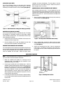
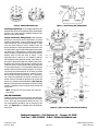
®
PRO-TUNER EFI DISTRIBUTORS WITH CAM-SYNC
Catalog #3615, 3616
INSTALLATION INSTRUCTIONS
PLEASE study these instructions carefully before beginning this installation. Most installations can be accomplished with common tools and
procedures. However, you should be familiar with and comfortable working on your vehicle. If you do not feel comfortable performing this installation,
it is recommended to have the installation completed by a qualified mechanic. If you have any questions, please call our Technical Hotline at:
1-800-416-8628, 7:00 am - 5:00 pm, Pacific Standard Time, Monday through Friday or e-mail us at [email protected].
IMPORTANT NOTE: Proper installation is the responsibility of the installer. Improper installation
will void your warranty and may result in poor performance and engine or vehicle damage.
DESCRIPTION: Pro-Tuner Distributors with Cam-Sync are designed for use with our Victor and Super Victor Pro-Tuner EFI systems. They are also
compatible with other aftermarket EFI management systems. These distributors include a large Ford-style distributor cap, locked out mechanical
advance. and a steel distributor drive gear. Chevrolet applications (only) include adjustable hold down collar to accommodate various deck heights and
intake manifolds. Pro-Tuner distributors also feature a Magnetic Crank Pickup and use a Hall-Effect Cam-Sync Pickup with LED indicator for the
Camshaft Sensor. The Cam-Sync pickup can be adjusted manually or with EFI management software to achieve the proper lead time required by your
ECU. The Cam Sync has a 12” lead and a 3-prong Weatherpak connector. The crank trigger has an 8” lead and 2-prong Weatherpak connector.
APPLICATIONS:
3615 - Small Block (283-400 CID) & Big Block Chevrolet V8 (396-502 CID)
3616 - Pontiac V8 (389-455 CID)
KIT CONTENTS:
❑ 1 Pro-Tuner Distributor
❑ 1 Rotor (MSD #8421)
❑ 1 Distributor Cap (MSD #8408)
❑ 1 Wire Retainer
❑
❑
❑
❑
2
1
2
1
1.5” Long, Self Tapping Screws
Distributor Gasket
O-Rings (3615 only)
Tube of Assembly Lube
BEFORE BEGINNING INSTALLATION
WARNING: When installing the distributor, make sure to disconnect the vehicle’s battery BEFORE beginning the installation.
NOTE: If the drive gear is ever replaced, you must use a MSD #8531 distributor drive gear due to the .500” diameter drive shaft.
•
HALL-EFFECT PICKUP
LED OPERATION: The LED is on whenever the magnet is NOT in front of the pickup. The LED Turns off when the magnet passes over the
center of the pickup (approximately 40°) (See Figure 1).
Specifications
Accepts 5-18 Volts continuous
Output: Within 1.5 volts on the red wire, and .3 volts above ground
Protected from reverse polarity, short circuit and over voltage
Figure 1 - Hall Effect Sensor
Catalog #3615, 3616
Rev. 6/07 - RS/mc
Page 1 of 4
©2007 Edelbrock Corporation
Brochure #63-3615
O-RING SEALS (3615 ONLY)
The Pro-Tuner Distributor features an o-ring groove in the uppermost
bottom land of the housing in order to seal the oil gallery. The o-ring
should only be installed if the block has been modified (See Figure 2).
revolutions and remove the distributor. The mesh pattern in the lube
should be even and in the middle of the gear. Adjust the slip collar to
obtain the proper mesh, if necessary.
CHECKING THE OIL PUMP TO DISTRIBUTOR SHAFT OVERLAP
After checking the drive gear mesh. it is very important to have the
proper overlap between the the distributor shaft and the oil pump shaft.
The tongue of the distributor shaft should sit into the oil pump shaft
groove by a minimum of 1/4”. Check this measurement according to the
procedure below:
1.
Measure the distance between the base of the slip collar and the tip
of the distributor shaft (See Figure 3).
Figure 2 - Block Modification O-Ring (Dual O-Ring Type Shown)
ADJUSTABLE SLIP COLLAR (3615 ONLY)
The Pro-Tuner Distributor features an adjustable slip collar. This allows
the distributor to accommodate variations in block height, modified
intake manifolds or cylinder heads. It is recommended to check the slip
collar setting before installation:
1.
Loosen the slip collar and insert the distributor into the engine until
it bottoms out on the oil pump drive.
2.
Raise the distributor .010” to .030” from bottomed out, then slide
the slip collar down into position and tighten the collar.
CHECKING THE DISTRIBUTOR DRIVE GEAR MESH
Figure 3 - Oil Pump Shaft to Distributor Shaft Overlap
2.
Using a straight edge, measure the distance from the intake
manifold distributor flange to the top of the oil pump intermediate
shaft (See Figure 3).
3.
Subtract the measurement from Step 1 from the measurement
taken in Step 2. This difference is the overlap. If there is too much,
or not enough clearance, a shorter or longer oil pump drive shaft will
be required.
It is recommended to check for proper gear mesh between the drive gear
on the camshaft and the drive gear on the distributor. In order to check
the mesh, coat the distributor gear with the supplied assembly lube and
install the distributor into the engine. Rotate the engine several
INSTALLATION PROCEDURE
NOTE: If installing distributor with an Edelbrock Pro-Tuner EFI kit, see
your User’s Guide for detailed installation instructions.
1.
Rotate the crankshaft until cylinder #1 is coming up on the
compression stroke. Stop turning when the crankshaft is at the
desired initial timing (i.e. 10° BTDC).
2.
Liberally apply assembly lube to the distributor gear. Install the
distributor (using the supplied gasket) so that the rotor comes to rest
pointing at what will be the #1 terminal on the cap (See Figure 4).
Position the cap such that #1 is in the same location as it was on
your previous distributor. Remove and reinsert the distributor to
align the distributor, if necessary. Make sure the distributor seats
down completely and has fully engaged the oil pump drive. You may
need to rotate the oil pump shaft.
3.
Lift the rotor by hand to make sure that there is adequate endplay.
Lack of endplay indicates that the rotor shaft is bottomed out on the
oil pump shaft.
Catalog #3615, 3616
Rev. 6/07 - RS/mc
Page 2 of 4
Figure 4 - Marking Rotor Position
©2007 Edelbrock Corporation
Brochure #63-3615
4.
Lightly tighten the hold down clamp so that the distributor can still
be turned to determine final setting when checking the timing.
5.
Re-attach the distributor cap. Make sure the rotor is still pointing to
#1.
6.
Install your spark plug and coil wires and connect the distributor to
the wiring harness. Make sure to install the spark plug wires one at
a time and verify they are in the correct position. A wire retainer is
supplied to secure the wires to the cap. Align the retainer with the
mounting bosses, and use the supplied 1.5” self-tapping screws to
secure the retainer.
NOTE: DO NOT use a Solid-Core type spark plug wire set, such
as copper core, etc. You must use a suppression type spark
plug wire. Failure to use the correct wires will cause electrical
interference with the engine control unit.
SETTING THE CAM SYNC PICKUP
The Hall-Effect pickup is designed to provide an aftermarket ECU with a
sync signal. This signal must be advanced more than the ignition trigger
signal. The amount of advance or lead time depends upon the ECU being
used. Always check with the ECU manufacturer for the amount of lead
time required for the cam sync.
NOTE: Adjustment to the cam sync pickup is not necessary when
using the distributor with Edelbrock Pro-Tuner EFI kit 3670 or 3690.
For all other installations, refer to Figure 5 and 6 for examples of
the display of the crank and cam sync sensor outputs.
1.
After the distributor is locked in place at the desired total timing,
rotate the engine until the #1 cylinder is at the required cam sync.
For example: If 10° of sync is required, and the total timing is at 36°
BTDC, rotate the engine until the #1 cylinder is at 46° BTDC.
2.
With power going to the Hall-Effect pickup, adjust the pickup until
the light turns off (The voltage output will be higher. Refer to the
Hall-Effect sensor information on page 1 for reference). This will be
the advance for the ECU. It is important to rotate the pickup
clockwise until the light turns on, and then rotate the pickup
counter-clockwise until the light just turns off.
3.
Lock the pickup sync in position.
Figure 6 - View of Distributor Output Signal
ROTOR PHASING
Rotor phasing is defined as the alignment between the rotor tip and the
distributor cap terminal when the spark occurs (See Figure 7). This
position can be very important to your engine’s performance. If the
alignment is incorrect, the spark will jump to the next closest terminal, or
another ground resulting in a misfire and loss of power. In applications
with extreme cylinder pressures, such as with nitrous or forced induction,
correct rotor phasing increases in importance. More voltage is required
to ionize the plug gap and if rotor phasing is off, the spark is more apt to
find an easier path to ground rather than the correct cap terminal. This
may result in severe engine damage.
Figure 7 - Rotor Phasing
In order to check rotor phasing, you will need to modify a distributor cap
so you can observe the rotor tip with a timing light when the engine is
running. Drill a large hole into a cap near a terminal that will allow you
an easy view of the terminal (See Figure 8). To help see the rotor tip,
mark it with white correction fluid. With the modified cap installed,
connect the timing light to the corresponding plug wire. Start the engine
and run at a steady speed. Shine the timing light into the cap and make
note of the relation of the rotor tip to the terminal when spark occurs.
Since the timing is going to be controlled electronically, it is important to
position the rotor phasing at, or near the total timing (most advanced).
Figure 5 - View of Distributor Output Signal
Catalog #3615, 3616
Rev. 6/07 - RS/mc
Page 3 of 4
©2007 Edelbrock Corporation
Brochure #63-3615
Figure 8 - Modified Distributor Caps
Figure 9 - Rotor Phasing with Timing Control
Crank Trigger Applications: In crank trigger applications, the
distributor does not control the ignition timing so adjusting rotor
phasing is easy. Simply rotate the distributor housing until the
rotor tip is in the correct position.
Phasing and Electronic Timing Controls: When setting the
phasing, you also need to take into consideration any timing
controls or retard controls. If you are advancing or retarding the
timing electronically, you are affecting rotor phasing. In most
cases, the timing change will not be enough to affect the
phasing, but there are certain applications to watch out for. One
such application is engines using multiple stage nitrous systems
and retard steps. High performance, nitrous engines undergo
extreme increases in cylinder pressures, which is why timing is
generally taken out with each stage of nitrous. If your
application pulls out a total of 16°, it is important to take this
into consideration when setting the phasing. If you remove 16°
of timing, the rotor tip will be past the cap terminal when it fires.
On engines with extreme cylinder pressures and high rpm, this
could easily cause a misfire or spark scatter which could result
in severe engine damage. It is recommended to divide the total
amount of retard and set the phasing at that point. For example,
if the timing retard control takes out 16° of timing, you should
set the rotor phasing when the timing is 8° retarded. This way,
with no retards activated the phasing will be 8° advanced, or
just in front of the distributor cap terminal and when the full
amount of retard is activated, the phasing will be just after the
terminal (on clockwise rotating distributors) (See Figure 9).
Whenever checking the rotor phasing with an electronic timing
control, it is important to check it with the retard activated and
not activated.
NOTE: Re-check the Cam Sync position after setting the
rotor phasing.
CARE AND MAINTENANCE
Periodically, visually inspect the cap terminals and rotor tip for
wear and look for traces of carbon tracking where spark scatter
occurs. Check your spark plug wires for burns or tears. It is
also recommended to periodically test the resistance of the
wires. See Figure 10 for an exploded view of the distributor
and its parts.
Figure 10 - Typical Pro-Tuner Distributor (3615 Shown)
Edelbrock Corporation • 2700 California St. • Torrance, CA 90503
Tech-Line: 1-800-416-8628 • E-Mail: [email protected]
Catalog #3615, 3616
Rev. 6/07 - RS/mc
Page 4 of 4
©2007 Edelbrock Corporation
Brochure #63-3615