1
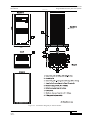
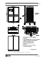
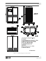
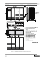
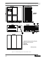
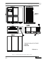
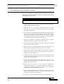
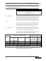
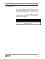
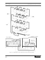
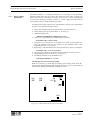
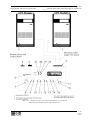
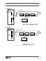
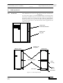
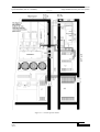
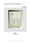
Chapter 3 - Installation Procedure Introduction 7400 Series UPS User Manual Single Module and One plus One Systems 6310018a.02.doc 3.1.1 The UPS cabinets can be moved by fork lift or crane. Fork lift apertures Equipment positioning are provided in the sides of the base plate and are accessible after and environmental removing blanking covers fitted to the side panel ventilation grills. Roofconsiderations mounted eye-bolts are fitted to enable the cabinet to be crane-handled. These can be removed once the equipment has been finally positioned. Note: In a 1 + 1 system the models should be positioned adjacent to each other. WARNING Ensure that the UPS weight is within the designated S.W.L. of any handling equipment. See the UPS specification for weight details. Do not move the battery cabinet with the batteries fitted.. The 300kVA and 400 kVA UPS modules are split into two cabinets, a Main Inverter cabinet and a Rectifier/Static Bypass cabinet, to allow easier transportation and positioning. Once finally positioned, the two cabinets have to be bolted together and the interlinking power and control cable connections made. It is therefore necessary to observe cabinet A & B positioning (see figures 3-5 and 3-6 ). The UPS module should be located in a cool, dry, clean-air environment with adequate ventilation to keep the ambient temperature within the specified operating range. If necessary, a system of extractor fans should be installed to aid cooling-air flow, and a suitable air filtration system used where the UPS is to operate in a dirty environment. Cables All control cables whether screened or not, should be run, separate from the power cables, in metal conduits or metal ducts which are electrically bonded to the metalwork of the cabinets to which they are connected. Cooling air flow All the models in the 7400 range are force-cooled with the aid of internal fans. Cooling air enters the module through ventilation grills located at various parts of the cabinet and exhausted through grills located in the equipment roof. When the equipment is located on a raised floor, and bottom cable entry is used, additional cooling air also enters the UPS via the floor void. Clearances To allow adequate cooling air flow, you should position the equipment with the following space around the back and sides. 80kVA-120 kVA Models 100mm minimum required in all cases. 200/300/400 kVA Models 300mm minimum required in all cases. The UPS modules do not require back-access for maintenance servicing; but, where space permits, a clearance of approximately 4 feet (1.2 metres) will ease access to some component parts. Clearance around the front of the equipment should be sufficient to enable free passage of personnel with the doors fully opened. 3-2 Issue 2 (02/98)