1
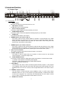
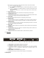
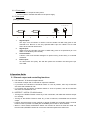
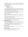
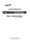
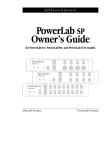
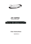
LIGHT COPILOT II
UserInstructions
(Rev1.024-004-1264)
E-mail: info@ elationlighting.com
Internet: http://www.elationlighting.com
1 Introduction
Thank you for your purchase of the LIGHT COPILOT II.
The LIGHT COPILOT II is a lighting controller, which can be used together with the LC-8SP relay
pack. The LIGHT COPILOT II has a total of 16 Channel outputs available for your convenience.
AUDIO and CHASE controls are also available in this unit. A built-in microphone is provided for
easy audio control. The “LATCH” function can override the chase function to keep an individual
channel “on”, while the other channels continue their chase sequence normally. There are 16
built-in programs for chasing effects, which can be operated, in MANUAL mode or in AUTO
mode. This user manual contains important information for you the user, please read it carefully
before use.
Warning
• Keep the unit dry, do not expose it to water or high levels of humid.
• Reduce the risk of electric shock or fire during operation.
• Do not attempt to dismantle or modify the unit.
• Do not make any inflammable liquids, water or metal objects enter the unit.
• No user serviceable parts inside, always consult qualified personnel for repairs.
• Turn off the power if not using this unit for a long period.
• This product can be used by adults only, do not allow children to play with it.
Customer Support: Elation Professional® provides a customer support line, to provide
set up help and to answer any question should you encounter problems during your set
up or initial operation. You may also visit us on the web at www.elationlighting.com for
any comments or suggestions. For service related issue please contact Elation
Professional®. Service Hours are Monday through Friday 9:00 a.m. to 5:00 p.m. Pacific
Standard Time.
Voice:
(323) 582-3322
Fax:
(323) 582-3108
E-mail:
[email protected]
Warning! To prevent or reduce the risk of electrical shock or fire, do not expose this
unit to rain or moisture.
Caution! There are no user serviceable parts inside this unit. Do not attempt any
repairs yourself, doing so will void your manufactures warranty.
Please do not discard the shipping carton in the trash. Please recycle when ever
possible.
2
Safety Warnings!
• To reduce the risk of electrical shock or fire, do not expose this unit to rain or
moisture.
• Do not spill water or other liquids into or on to your unit.
• Do not attempt to remove or break off the ground prong from the electrical
cord. This prong is used to reduce the risk of electrical shock and fire in case
of an internal short. Do not attempt to operate this unit if the power cord has
been frayed or broken.
• Disconnect from main power before making any type of connection.
• Do not remove the cover under any conditions. There are no user serviceable
parts inside.
• Always be sure to mount this unit in an area that will allow proper
ventilation. Allow about 6” (15cm) between this device and a wall.
• Do not attempt to operate this unit, if it becomes damaged.
• This unit is intended for indoor use only, use of this product outdoors voids
all warranties.
• During long periods of non-use, disconnect the unit’s main power.
• Always mount this unit in safe and stable matter.
• Power cords should be routed so they are not likely to be walked on, pinched
by items placed upon or against them.
• Cleaning -The fixture should be cleaned only as recommended by the
manufacturer. See page 3 for cleaning details.
• Heat -The appliance should be situated away from heat sources such as
radiators heat registers, stoves, or other appliances (including amplifiers) that
produce heat.
• The fixture should be serviced by qualified service personnel when:
A. The power-supply cord or the plug has been damaged.
B. Objects have fallen, or liquid has been spilled into the unit.
C. The unit has been exposed to rain or water.
D. The unit does not appear to operate normally or exhibits a marked
change in performance.
3
2 Controls and Functions
2.1 Product View
1
POWER
3
2
AUDIO
USB LIGHT
Min
CH1 - 8
5
4
SPEED
Max
Min
FLASH
Max
FLASH
SPEED
Min
MANUAL
AUDIO
FLASH
CH1-16
8
LATCH
9
7
6
SPEED
CH1-4 /
CH9-12
Max
14
Min
16 PRE PROGRAMS
Ch5 - 8 /
CH13-16
Max
16
1
LATCH
2
3
19 20 21
4
5
6
7
8
ON
ON
ON
ON
ON
ON
ON
ON
OFF
OFF
OFF
OFF
OFF
OFF
OFF
OFF
Ready
EFFECT
MANUAL
Heating
FOG
MACHINE
AUDIO
x1
10min
OFF
AUTO
10
CHASE
AUTO
FLASH
9
13
12
11
10
15
11
12
16
13
14
15
16
STAND BY
17 18
2.1.1 Front panel
1.
Power switch:
This switch is used to turn the main power on or off.
2.
USB LIGHT connector:
A USB LIGHT can be connected here.
3.
Audio sensitivity adjuster:
This knob is used to adjust the audio sensitivity of the unit.
4.
FLASH SPEED adjuster:
This knob is used to control and adjust the flashing frequency of the strobes.
5.
FLASH LED:
This indicates that status of the strobes.
6. SPEED adjuster upon CH1-4 / CH9-12:
This knob is used to set the Chase speed for channels 1-4 and channels 9-12. Chase
speed adjustment for channels 9-12 can only be set in 16-channel output mode only.
Turning the knob towards “Max” will make the chase faster, while turning the knob
towards “Min” will make the chase slower.
7. SPEED adjuster upon CH5-8 / CH13-16:
This knob is used to set the Chase speed for channels 5-8 and channels 13-16. Chase
speed adjustment for channels 13-16 can only be set in 16-channel output mode. User
can get higher (lower) speed levels by adjusting the knob towards “Max” ( “Min”).
8. CH1-8 / CH1-16 selector:
This switch is used to select either 8-channel output or 16 channel.
9. FLASH / LATCH selector:
This switch is used to select either the FLASH or LATCH function for the relevant
channel buttons in 16-channel output mode.
10. FLASH SPEED selector:
This switch is used to select the flash speed mode of the strobes. There are three modes:
(1) AUDIO - flash speed is controlled by audio signals.
(2) FLASH - flash speed is set by the FLASH SPEED adjuster.
(3) OFF - switches the strobes off.
11. Mode Button:
These buttons are used to select a Chase program between program 1 and program
16 in MANUAL mode. Each tap of the button will change the Chase program once. The
left Mode button is for CH1-4 / CH9-12, and the right Mode button is for CH5-8 / CH1316.
12. MANUAL / AUTO selector:
Use this switch to select between either MANUAL mode or AUTO mode. Select
MANUAL mode to run any of the 16 built-in programs manually, or select AUTO mode,
to have all 16 programs run continuously and automatically. The left switch controls
CH1-4 / CH9-12, and the right switch controls CH5-8 / CH13-16.
13. CHASE mode selector:
4
LIGHT COPILOT II
Used to select the corresponding Chase speed control mode. There are three modes:
(1) AUDIO - controlled by audio signals.
(2) _x1 - controlled by the SPEED adjuster, the fastest Chase speed can be within a
few seconds.
(3) 10 min -_controlled by the SPEED adjuster, the slowest Chase speed can be
within a few minutes.
The left switch controls CH1-4 / CH9-12, and the right switch controls CH5-8 /
CH13-16.
14. EFFECT Switches (x8):
Use these switches to activate or deactivate the corresponding channels output.
15. CHANNEL Buttons (x16):
These buttons can lock (LATCH) or trigger (FLASH) the corresponding channels output,
(according to the setting of the FLASH / LATCH selector switch).
16. Channel LED:
The channel LED indicates the status of corresponding channels output.
17. STAND BY LED:
This LED indicates the status of the STAND BY function. When the LED is “blinking”, it
means the output is not active, while when the LED is “off” it means the output is active.
18. STAND BY button:
This button disables the all output momentarily. While pressing this button for a second
time, the channel output will be reactivated.
19. READY LED:
This LED indicates the status of the fog Machine. When the LED is lit the Fog Machine
is READY.
20. HEATING LED:
This LED indicates that the fog machine is connected correctly. When the LED is lit, it
indicates that t the connection is OK.
21. Fog Machine button:
Pressing this button after the READY LED is lit; will activate the fog machine.
2.1.2 Rear panel
PIN
1
2
3
4
5
6
7
8
9
PIN
1
2
3
4
5
6
7
8
9
CH
VCC
12
11
10
9
16
15
14
13
CH
VCC
4
3
2
1
8
7
6
5
CONTROL OUTPUT 9 - 16
1
1.
2.
3.
4.
5.
6.
CONTROL OUTPUT 1 - 8
DC INPUT:
9-12VDC,500mA
FOG MACHINE
3
2
AUDIO IN
STROBE OUTPUT
4
5
MADE IN PRC
6
CH9-16 outlet: to output signals according to 9-16 channels.
CH1-8 outlet: to output signals according to 1-8 channels.
Fog machine connector: connects to a fog machine using a 5-pin cable. Compatible
fog machines include the Vaporizer™, Vapor Flow™, Fog Storm 1200™ and
1700™.
Audio input: to input audio signals.
Strobe output: 1/4” mono jack for output to strobes.
DC input: used to plug in the external power supply (9 ~12V DC 500mA).
2.2 Relay Pack
5
23-001-2105
2.2.1 Front panel
•
•
Power socket: to output the main power.
Power indicator: indicates the status of the power supply.
2.2.2 Rear panel
(Relay pack-side view)
AC 120V~60Hz, 15A
OUTPUT
1
1.
2.
3.
4.
CIRCUIT BREAKER
INPUT
2
3
AC POWER
4
Signal output:
This 9-pin com connection is used to connect another LC-8SP relay pack to the
controller unit. Be sure to use only specified ADJ 9-pin com cables. This is used
when all 16 channels will be used
Signal input:
Used to link the controller unit with LC-8SP relay pack via a specified 9-pin com
cable or LC Wireless (not included).
Circuit breaker:
A built-in 15A circuit breaker designed to protect wiring under heavy or overload
conditions.
Power input:
AC 120V--60Hz 15A (max), this will also power the controller unit through the pin
com cable.
3 Operation Guide
3.1 Channel output and controlling functions
3.1.1 8 channel / 16 channel output control:
• 8 channels of output and 16 channels of output are available.
• If you switch the CH1-8/CH1-16 selector switch to “CH1-8” position, then only 8-channels
are active and available for use.
• If you switch the CH1-8/CH1-16 selector switch to “CH1-16” position, then all 16-channels
are active and available for use.
3.1.2 EFFECT / LATCH / FLASH function:
• Turning on the EFFECT Switch under any of the 8 channels, will make that channels output
run normally.
• Turning off the EFFECT Switch under any of the 8 channels, will disable that channels
output.
• Press a Channel button to lock (LATCH) or trigger (FLASH) the channels output. Channel
button functions (LATCH or FLASH) are controlled by the FLASH / LATCH selector.
• When in 16-CH mode, the EFFECT Switch can function as well as in the 8-CH mode. On
the other hand, EFFECT Switch can control two channel outputs at the same time.
6
For example: The EFFECT switch which controls channel 1 can simultaneously control
channel 9 in 16-CH mode. The function of each Channel button will be controlled by the
FLASH / LATCH selector switch. Select “LATCH” for the LATCH function, and select
“FLASH” for the FLASH function.
3.1.3 Chase speed control:
Chase speed can be controlled by:
a. Audio signals.
b. SPEED adjuster in x1 mode.
c.
SPEED adjuster in 10 min mode.
• Switch the “Chase mode selector” to AUDIO mode; the Chase speed will now be controlled
by incoming audio signals. Audio sensitivity is controlled by the Audio sensitivity adjuster —
you can make audio sensitivity greater by turning the knob towards “Max”, and make the
audio sensitivity lower by turning the knob towards “Min”.
• Switch the “Chase mode selector” to x1 mode, the SPEED adjuster will control the Chase
speed, the fastest the Chase speed can be is within a few seconds.
• Switch the “Chase mode selector” to the 10min mode, the SPEED adjuster will control the
Chase speed, the slowest the Chase speed can be is 10 minutes.
3.1.4 MANUAL / AUTO Mode
• By switching the MANUAL/AUTO selector to MANUAL mode, you can select any of the
built-in chasing programs by pressing the Mode button. Each tap will change the program
once.
• When the MANUAL/AUTO selector switch is set to AUTO mode, then all 16 built-in chasing
programs will run continuously and automatically.
3.1.5 Enable / disable signal output for Relay Pack
• The signal output for Relay Pack can be controlled by the STAND BY button. When the
STAND B Y LED blinks, that means the signal output is disabled (blackout). Press the
STAND BY button again (LED is off”) to reactivate the signal output.
3.2 External strobes control
External strobes can be controlled in the following different flash speed modes.
• Switch the “FLASH SPEED selector switch” to AUDIO mode; and the strobes will flash
according to the incoming audio signals.
• Switch the “FLASH SPEED selector switch” to FLASH mode, and the strobes will be
controlled by the FLASH SPEED adjuster — turn the knob towards “Max” to increase the
speed level, and turn the knob towards “Min” to decrease the speed level.
• Switch the “FLASH SPEED selector switch” to OFF, and the strobes will be disabled.
3.3 Usage of USB light
• To use the USB LIGHT, connect the USB LIGHT to the USB socket on the front panel of the
controller, and then turn on the power switch.
3.4 Fog Machine trigger
• When the HEATING LED is lit, it means the Fog Machine has connected.
• When the READY LED is lit, it means that the Fog Machine is ready to run.
• Press the FOG MACHINE button to activate the fog machine.
7
Warranty
2-YEAR LIMITED WARRANTY
A. Elation Professional® hereby warrants, to the original purchaser, Elation Professional®
products to be free of manufacturing defects in material and workmanship for a period of two
years, (730 days) from the date of purchase. This warranty shall be valid only if the product is
purchased within the United States of America, including possessions and territories. It is the
owner’s responsibility to establish the date and place of purchase by acceptable evidence, at the
time service is sought.
B. For warranty service, send the product only to the Elation Professional® factory. All shipping
charges must be pre-paid. If the requested repairs or service (including parts replacement) are
within the terms of this warranty, Elation Professional® will pay return shipping charges only to
a designated point within the United States. If the entire instrument is sent, it must be shipped
in its original package. No accessories should be shipped with the product. If any accessories
are shipped with the product, Elation Professional® shall have no liability whatsoever for loss of
or damage to any such accessories, nor for the safe return thereof.
C. This warranty is void if the serial number has been altered or removed; if the product is
modified in any manner which Elation Professional® concludes, after inspection, affects the
reliability of the product; if the product has been repaired or serviced by anyone other than the
Elation Professional® factory unless prior written authorization was issued to purchaser by
Elation Professional®; if the product is damaged because not properly maintained as set forth in
the instruction manual.
D. This is not a service contract, and this warranty does not include maintenance, cleaning or
periodic check-up. During the period specified above, Elation Professional® will replace
defective parts at its expense, and will absorb all expenses for warranty service and repair labor
by reason of defects in material or workmanship. The sole responsibility of Elation
Professional® under this warranty shall be limited to the repair of the product, or replacement
thereof, including parts, at the sole discretion of Elation Professional®. All products covered by
this warranty were manufactured after January 1, 1990, and bare identifying marks to that
effect.
E. Elation Professional® reserves the right to make changes in design and/or improvements
upon its products without any obligation to include these changes in any products theretofore
manufactured.
F. No warranty, whether expressed or implied, is given or made with respect to any accessory
supplied with products described above. Except to the extent prohibited by applicable law, all
implied warranties made by Elation Professional® in connection with this product, including
warranties of merchantability or fitness, are limited in duration to the warranty period set forth
above. And no warranties, whether expressed or implied, including warranties of
merchantability or fitness, shall apply to this product after said period has expired. The
consumer’s and or Dealer’s sole remedy shall be such repair or replacement as is expressly
provided above; and under no circumstances shall Elation Professional® be liable for any loss
or damage, direct or consequential, arising out of the use of, or inability to use, this product.
G. This warranty is the only written warranty applicable to Elation Professional® Products and
supersedes all prior warranties and written descriptions of warranty terms and conditions
heretofore published.
8
4 Specifications
Power input LIGHT COPILOT II…………………………………….………DC 9 ~12V, 500mA min.
Power input LC-8SP….…………………….……………………………..AC 120V 60Hz, 15A (max)
Channel output…………………………………………………..10A per channel, TOTAL 15A (max)
Breaker………………………………………………………………..…………… 15A 250V 5_20mm
USB output………………………………………………………………..………..DC 5V 100mA(max)
Strobe output……………………………………………………Pulse 10Vp-p(frequency adjustable)
Audio input……………………………………………………………………….Line input 0.1V~1Vp-p
Dimensions…………………………………………………………………...………..480_83_43mm
Weight…………………………………………………………………………………....2.6lb / 1.2kg
9