1
Table of Contents, cont’d
4
4.0
4.1
4.2
4.3
4.4
4.5
4.5.1
4.5.2
4.6
4.6.1
4.6.2
INSTALLATION OF REMOTE HEAT EXCHANGER ......................................... 18
Rigging ................................................................................................................ 18
Leg Assembly ...................................................................................................... 18
Locating the Remote Heat Exchanger ................................................................ 18
Electrical Service ................................................................................................. 19
Air Cooled Condensers - Model DARC ............................................................... 19
Fan Speed Control .............................................................................................. 19
Ambient Thermostats .......................................................................................... 19
Fluid Coolers - Model DAFC ............................................................................... 20
Fluid-Sensing Thermostats ................................................................................. 20
Energy Saver Cooling ......................................................................................... 20
5.0
5.1
5.1.1
5.1.2
5.2
5.2.1
5.2.2
5.2.3
5.3
5.3.1
5.3.2
5.4
5.4.1
5.5
CHARGING ........................................................................................................ 21
Voltage Phase Check .......................................................................................... 21
Evaporator ........................................................................................................... 21
Secondary Heat Exchanger ................................................................................ 21
Important Refrigeration Components .................................................................. 21
Expansion Valve .................................................................................................. 21
High Pressure Cutout Switch .............................................................................. 21
Low Pressure Cutout Switch ............................................................................... 22
Air Cooled Systems ............................................................................................. 22
Fan Speed Control System Charging.................................................................. 22
Flooded System Charging ................................................................................... 23
Water/Glycol Cooled Systems ............................................................................. 24
Water/Glycol Cooled Systems Charging ............................................................. 24
Refrigerant Handling ........................................................................................... 24
6.0
6.1
6.2
6.3
6.4
6.5
6.6
GLYCOL SYSTEMS ........................................................................................... 25
Glycol Concentration ........................................................................................... 25
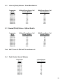
Internal (Fluid) Volume - Downflow Models ......................................................... 25
Internal (Fluid) Volume - Upflow Models ............................................................. 25
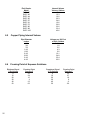
Fluid Cooler Internal Volume ............................................................................... 26
Copper Piping Internal Volume............................................................................ 26
Freezing Point of Aqueous Solutions .................................................................. 26
7.0
7.1
7.2
7.3
CONTROLS ....................................................................................................... 27
DAP® III Microprocessor Control Panel ............................................................... 27
Secondary Heat Exchangers............................................................................... 27
Wiring Diagrams .................................................................................................. 27