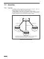
1
ROBOT
Vertical articulated
V*-D/-E SERIES
Horizontal articulated
H*-D/-E SERIES
Cartesian coordinate
XYC-4D SERIES
Vision device
µVision-21 SERIES
PROGRAMMER’S MANUAL I
PROGRAM DESIGN AND COMMANDS
(Ver. 1.95)
Copyright © DENSO WAVE INCORPORATED, 2002
All rights reserved. No part of this publication may be reproduced in any form or by any means without
permission in writing from the publisher.
Specifications are subject to change without prior notice.
All products and company names mentioned are trademarks or registered trademarks of their
respective holders
Preface
Thank you for purchasing this high-speed, high-accuracy assembly robot.
Before operating your robot, read this manual carefully to safely get the maximum benefit from your
robot in your assembling operations.
Robot series and/or models covered by this manual
- Vertical articulated robot
V*-D/-E series
- Horizontal articulated robot
H*-D/-E series
- Cartesian coordinate robot
XYC-4D series
- Vision devaicec
µVision-21 series
Robot controller version (Note)
- Applicable to up to Ver. 1.9 of the RC5 type controller.
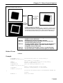
Note: The robot controller version is indicated in the main software ver. column of the controller setting
table affixed on the controller. It can also be confirmed from the teaching pendant by reading the
ROM version column displayed by “basic screen” - “F6 setting” - “F6 maintenance” - “F2 version”.
Important
To ensure operator safety, be sure to read the precautions and instructions in "SAFETY
PRECAUTIONS," pages 1 through 9.
i
How the documentation set is organized
The documentation set consists of the following books. If you are unfamiliar with this robot and
option(s), please read all books and understand them fully before operating your robot and option(s).
GENERAL INFORMATION ABOUT ROBOT
Provides the packing list of the robot and outlines of the robot system, robot unit, and robot
controller.
INSTALLATION & MAINTENANCE GUIDE
Provides instructions for installing the robot components and customizing your robot, and
maintenance & inspection procedures.
BEGINNER'S GUIDE
Introduces you to the DENSO robot. Taking an equipment setup example, this book guides
you through running your robot with the teach pendant, making a program in WINCAPSII, and
running your robot automatically.
SETTING-UP MANUAL
Describes how to set-up or teach your robot with the teach pendant, operating panel, or minipendant.
WINCAPSII GUIDE
Provides instructions on how to use the teaching system WINCAPSII which runs on the PC
connected to the robot controller for developing and managing programs.
PROGRAMMER'S MANUAL (I), (II) - this book Describes the PAC programming language, program development, and command
specifications in PAC.
RC5 CONTROLLER
INTERFACE MANUAL
Describes the RC5 controller, interfacing with external devices, system- and user-input/output
signals, and I/O circuits.
ERROR CODE TABLES
List error codes that will appear on the teach pendant, operating panel, or PC screen if an
error occurs in the robot series or WINCAPSII. These tables provide detailed description and
recovery ways.
OPTIONS MANUAL
Describes the specifications, installation, and use of optional devices.
ii
How this book is organized
This book is just one part of the documentation set. This book consists of SAFETY PRECAUTIONS
and chapters one through five.
SAFETY PRECAUTIONS
Defines safety terms, safety related symbols and provides precautions that should be observed. Be
sure to read this section before operating your robot.
Commands Listed in Alphabetical Order
Commands Listed According to Functions
PART 1 PROGRAM DESIGN
Chapter 1 Sample Program
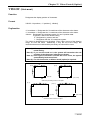
This chapter utilizes a simple application example to provide usage of each command.
Chapter 2 Program Flow
This chapter provides an explanation on the rules, which are required for creating a program, for the
operation of programs in the PAC language.
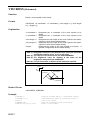
Chapter 3 Robot Motion
This chapter provides an explanation of various motions of the robot. The robot motion varies
according to the reference position and the decision method for reach destination position.
Chapter 4 Speed, Acceleration and Deceleration Designation
This chapter provides an explanation of the meanings and settings for speed, acceleration, and
deceleration.
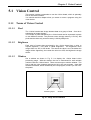
Chapter 5 Vision Control
This chapter provides explanations of terms related to vision that are required in creating a program.
iii
PART 2 COMMAND REFERENCE
Chapter 6 Guide to Command Reference
This chapter provides command descriptions and a command list for the PAC robot.
Use the command list to quickly search for information concerning each command.
Chapter 7 PAC Language Configuration Elements
This chapter provides an explanation of the element rules (identifier, variable, constant, operator,
expression, and command) which construct the PAC language.
Chapter 8 PAC Language Syntax
This chapter provides an explanation on the rules of syntax when you describe a program in the PAC
language.
Chapters 9 to 21
These chapters provide an explanation of each command in the PAC robot language. Commands are
classified by function.
To quickly find an explanation of a particular command, use the command list in CHAPTER 1.
Chapter 22 Appendices
Character Code Table
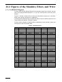
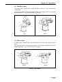
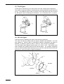
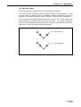
Figures of the Shoulder, Elbow, and Wrist
Environment Setting Values
Using Condition Parameters
Reserved Word List
Conventional Language Command Correspondence Table (VS)
Version Correspondence Table
Setting Parameter Table
Index
iv
SAFETY PRECAUTIONS
SAFETY PRECAUTIONS
Be sure to observe all of the following safety precautions.
Strict observance of these warning and caution indications are a MUST for preventing accidents, which
could result in bodily injury and substantial property damage. Make sure you fully understand all
definitions of these terms and related symbols given below, before you proceed to the text itself.
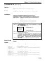
WARNING
Alerts you to those conditions, which could result
in serious bodily injury or death if the instructions
are not followed correctly.
CAUTION
Alerts you to those conditions, which could result
in minor bodily injury or substantial property
damage if the instructions are not followed
correctly.
Terminology and Definitions
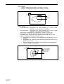
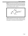
Maximum space: Refers to the volume of space encompassing the maximum designed movements of
all robot parts including the end-effector, workpiece and attachments. (Quoted from the RIA*
Committee Draft.)
Restricted space: Refers to the portion of the maximum space to which a robot is restricted by limiting
devices (i.e., mechanical stops). The maximum distance that the robot, end-effector, and workpiece
can travel after the limiting device is actuated defines the boundaries of the restricted space of the
robot. (Quoted from the RIA Committee Draft.)
Motion space: Refers to the portion of the restricted space to which a robot is restricted by software
motion limits. The maximum distance that the robot, end-effector, and workpiece can travel after the
software motion limits are set defines the boundaries of the motion space of the robot. (The "motion
space" is Denso-proprietary terminology.)
Operating space: Refers to the portion of the restricted space (or motion space in Denso) that is
actually used by the robot while performing its task program. (Quoted from the RIA Committee Draft.)
Task program: Refers to a set of instructions for motion and auxiliary functions that define the specific
intended task of the robot system. (Quoted from the RIA Committee Draft.)
(*RIA: Robotic Industries Association)
1
1. Introduction
This section provides safety precautions to be observed during
installation, teaching, inspection, adjustment, and maintenance
of the robot.
2. Installation Precautions
2.1 Insuring the proper
installation environment
2.1.1 For standard type
The standard type has not been designed to withstand
explosions, dust-proof, nor is it splash-proof. Therefore, it
should not be installed in any environment where:
(1) there are flammable gases or liquids,
(2) there are any shavings from metal processing or other
conductive material flying about,
(3) there are any acidic, alkaline or other corrosive gases,
(4) there is cutting or grinding oil mist,
(5) it may likely be submerged in fluid,
(6) there is sulfuric cutting or grinding oil mist, or
(7) there are any large-sized inverters, high output/high
frequency transmitters, large contactors, welders, or other
sources of electrical noise.
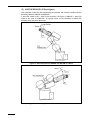
2.1.2 For dust-proof, splashproof type
The dust-proof, splash-proof type is an IP54-equivalent dustproof and splash-proof structure, but it has not been designed
to withstand explosions. (The wrist of the VM-D-W and VS-E-W
is an IP65-equivalent dust-proof and splash-proof structure.)
Note that the robot controller is not a dust- or splash-proof
structure. Therefore, when using the robot controller in an
environment exposed to mist, put it in an optional protective
box.
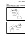
The dust-proof, splash-proof type should not be installed in any
environment where:
(1) there are any flammable gases or liquids,
(2) there are any acidic, alkaline or other corrosive gases,
(3) there are any large-sized inverters, high output/high
frequency transmitters, large contactors, welders, or other
sources of electrical noise,
(4) it may likely be submerged in fluid,
(5) there are any grinding or machining chips or shavings,
(6) any machining oil other than DENSO authorized oil is in
use, or
Note: DENSO authorized oil: Yushiron Oil No. 4C (nonsoluble)
(7) there is sulfuric cutting or grinding oil mist.
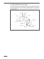
2.2 Service space
2
The robot and peripheral equipment should be installed so that
sufficient service space is maintained for safe teaching,
maintenance, and inspection.
SAFETY PRECAUTIONS
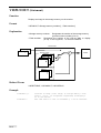
2.3 Control devices
outside the robot's
restricted space
The robot controller, teach pendant, and operating panel should
be installed outside the robot's restricted space and in a place
where you can observe all of the robot’s movements when
operating the robot controller, teach pendant, or operating
panel.
2.4 Positioning of gauges
Pressure gauges, oil pressure gauges and other gauges should
be installed in an easy-to-check location.
2.5 Protection of electrical
wiring and
hydraulic/pneumatic
piping
If there is any possibility of the electrical wiring or
hydraulic/pneumatic piping being damaged, protect them with a
cover or similar item.
2.6 Positioning of
emergency stop
switches
Emergency stop switches should be provided in a position
where they can be reached easily should it be necessary to
stop the robot immediately.
(1) The emergency stop switches should be red.
(2) Emergency stop switches should be designed so that they
will not be released after pressed, automatically or
mistakenly by any other person.
(3) Emergency stop switches should be separate from the
power switch.
2.7 Positioning of
operating status
indicators
Operating status indicators should be positioned in such a way
where workers can easily see whether the robot is on
temporary halt or on an emergency or abnormal stop.
3
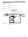
2.8 Setting-up the safety
fence or enclosure
A safety fence or enclosure should be set up so that no one can
easily enter the robot's restricted space. If it is impossible,
utilize other protectors as described in Section 2.9.
(1) The fence or enclosure should be constructed so that it
cannot be easily moved or removed.
(2) The fence or enclosure should be constructed so that it
cannot be easily damaged or deformed through external
force.
(3) Establish the exit/entrance to the fence or enclosure.
Construct the fence or enclosure so that no one can easily
get past it by climbing over the fence or enclosure.
(4) The fence or enclosure should be constructed to ensure
that it is not possible for hands or any other parts of the
body to get through it.
(5) Take any one of the following protections for the entrance/
exit of the fence or enclosure:
1) Place a door, rope or chain across the entrance/exit of
the fence or enclosure, and fit it with an interlock that
ensures the emergency stop device operates
automatically if it is opened or removed.
2) Post a warning notice at the entrance/exit of the fence
or enclosure stating "In operation--Entry forbidden" or
"Work in progress--Do not operate" and ensure that
workers follow these instructions at all times.
When making a test run, before setting up the fence or
enclosure, place an overseer in a position outside the
robot’s restricted space and one in which he/she can
see all of the robot’s movements. The overseer should
prevent workers from entering the robot's restricted
space and be devoted solely to that task.
2.9 Positioning of rope or
chain
If it is not possible to set up the safety fence or enclosure
described in Section 2.8, hang a rope or chain around the
perimeter of the robot’s restricted space to ensure that no one
can enter the restricted space.
(1) Ensure the support posts cannot be moved easily.
(2) Ensure that the rope or chain’s color or material can easily
be discerned from the surrounds.
(3) Post a warning notice in a position where it is easy to see
stating "In operation--Entry forbidden" or "Work in progress
--Do not operate" and ensure that workers follow these
instructions at all times.
(4) Set the exit/entrance, and follow the instructions given in
Section 2.8, (3) through (5).
4
SAFETY PRECAUTIONS
2.10 Setting the robot's
motion space
The area required for the robot to work is called the robot's
operating space.
If the robot’s motion space is greater than the operating space,
it is recommended that you set a smaller motion space to
prevent the robot from interfering or disrupting other equipment.
Refer to the "INSTALLATION & MAINTENANCE GUIDE"
Chapter 4.
2.11 No robot modification
allowed
Never modify the robot unit, robot controller, teach pendant or
other devices.
2.12 Cleaning of tools
If your robot uses welding guns, paint spray nozzles, or other
end-effectors requiring cleaning, it is recommended that the
cleaning process be carried out automatically.
2.13 Lighting
Sufficient illumination should be assured for safe robot
operation.
2.14 Protection from objects
thrown by the endeffector
If there is any risk of workers being injured in the event that the
object being held by the end-effector is dropped or thrown by
the end-effector, consider the size, weight, temperature and
chemical nature of the object and take appropriate safeguards
to ensure safety.
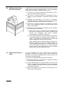
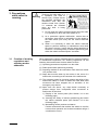
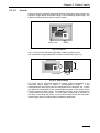
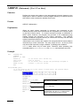
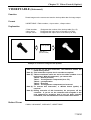
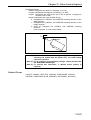
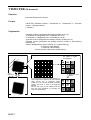
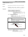
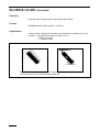
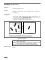
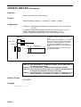
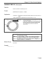
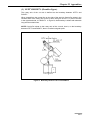
2.15 Affixing the warning
label
Place the warning label packaged
with the robot on the exit/entrance
of the safety fence or in a position
where it is easy to see.
5
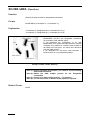
3. Precautions
while robot is
running
Warning
Touching the robot while it is
in operation can lead to
serious injury. Please ensure
the following conditions are
maintained and that the
cautions listed from Section
3.1 onwards are followed
when any work is being
performed.
1) Do not enter the robot's restricted space when the robot
is in operation or when the motor power is on.
2) As a precaution against malfunction, ensure that an
emergency stop device is activated to cut the power to
the robot motor upon entry into the robot's restricted
space.
3) When it is necessary to enter the robot's restricted
space to perform teaching or maintenance work while
the robot is running, ensure that the steps described in
Section 3.3 "Ensuring safety of workers performing jobs
within the robot's restricted space" are taken.
3.1 Creation of working
regulations and
assuring worker
adherence
When entering the robot’s restricted space to perform teaching
or maintenance inspections, set "working regulations" for the
following items and ensure workers adhere to them.
(1) Operating procedures required to run the robot.
(2) Robot speed when performing teaching.
(3) Signaling methods to be used when more than one worker
is to perform work.
(4) Steps that must be taken by the worker in the event of a
malfunction, according to the contents of the malfunction.
(5) The necessary steps for checking release and safety of the
malfunction status, in order to restart the robot after robot
movement has been stopped due to activation of the
emergency stop device
(6) Apart from the above, any steps below necessary to
prevent danger from unexpected robot movement or
malfunction of the robot.
1) Display of the control panel (See Section 3.2 on the
following page)
2) Assuring the safety of workers performing jobs within
the robot's restricted space (See Section 3.3 on the
following page)
3) Maintaining worker position and stance
Position and stance that enables the worker to confirm
normal robot operation and to take immediate refuge if
a malfunction occurs.
6
SAFETY PRECAUTIONS
4) Implementation of measures for noise prevention
5) Signaling methods for workers of related equipment
6) Types of malfunctions and how to distinguish them
Please ensure "working regulations" are appropriate to the
robot type, the place of installation and to the content of the
work.
Be sure to consult the opinions of related workers, engineers at
the equipment manufacturer and that of a labor safety
consultant when creating these "working regulations".
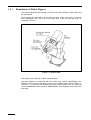
3.2 Display of operation
panel
To prevent anyone other than the worker from accessing the
start switch or the changeover switch by accident during
operation, display something to indicate it is in operation on the
operating panel or teach pendant. Take any other steps as
appropriate, such as locking the cover.
3.3 Ensuring safety of
workers performing
jobs within the robot's
restricted space
When performing jobs within the robot’s restricted space, take
any of the following steps to ensure that robot operation can be
stopped immediately upon a malfunction.
(1) Ensure an overseer is placed in a position outside the
robot’s restricted space and one in which he/she can see
all robot movements, and that he/she is devoted solely to
that task.
Q An emergency stop device should be activated
immediately upon a malfunction.
R Do not permit anyone other than the worker engaged
for that job to enter the robot’s restricted space.
(2) Ensure a worker within the robot's restricted space carries
the portable emergency stop switch so he/she can press it
(the robot stop button on the teach pendant) immediately if
it should be necessary to do so.
7
3.4 Inspections before
commencing work
such as teaching
Before starting work such as teaching, inspect the following
items, carry out any repairs immediately upon detection of a
malfunction and perform any other necessary measures.
(1) Check for any damage to the sheath or cover of the
external wiring or to the external devices.
(2) Check that the robot is functioning normally or not (any
unusual noise or vibration during operation).
(3) Check the functioning of the emergency stop device.
(4) Check there is no leakage of air or oil from any pipes.
(5) Check there are no obstructive objects in or near the
robot’s restricted space.
3.5 Release of residual air
pressure
Before disassembling or replacing pneumatic parts, first release
any residual air pressure in the drive cylinder.
3.6 Precautions for test
runs
Whenever possible, have the worker stay outside of the robot's
restricted space when performing test runs.
3.7 Precautions for
automatic operation
(1) At start-up
Before the robot is to be started up, first check the following
items as well as setting the signals to be used and perform
signaling practice with all related workers.
1) Check that there is no one inside the robot’s restricted
space.
2) Check that the teach pendant and tools are in their
designated places.
3) Check that no lamps indicating a malfunction on the
robot or related equipment are lit.
(2) Check that the display lamp indicating automatic operation
is lit during automatic operation.
(3) Steps to be taken when a malfunction occurs
Should a malfunction occur with the robot or related
equipment and it is necessary to enter the robot's restricted
space to perform emergency maintenance, stop the robot’s
operation by activating the emergency stop device. Take
any necessary steps such as placing a display on the
starter switch to indicate work is in progress to prevent
anyone from accessing the robot.
8
SAFETY PRECAUTIONS
3.8 Precautions in repairs
(1) Do not perform repairs outside of the designated range.
(2) Under no circumstances should the interlock mechanism
be removed.
(3) When opening the robot controller's cover for battery
replacement or any other reasons, always turn the robot
controller power off and disconnect the power cable.
(4) Use only spare tools authorized by DENSO.
4. Daily and periodical
inspections
(1) Be sure to perform daily and periodical inspections. Before
starting jobs, always check that there is no problem with the
robot and related equipment. If any problems are found,
take any necessary measures to correct them.
(2) When carrying out periodical inspections or any repairs,
maintain records and keep them for at least 3 years.
5. Management of
floppy disks
(1) Carefully handle and store the "Initial settings" floppy disks
packaged with the robot, which store special data
exclusively prepared for your robot.
(2) After finishing teaching or making any changes, always
save the programs and data onto floppy disks.
Making back-ups will help you recover if data stored in the
robot controller is lost due to the expired life of the back-up
battery.
(3) Write the names of each of the floppy disks used for storing
task programs to prevent incorrect disks from loading into
the robot controller.
(4) Store the floppy disks where they will not be exposed to
dust, humidity and magnetic field, which could corrupt the
disks or data stored on them.
9
10
CONTENTS
Preface.................................................................................................................................................................................i
How the documentation set is organized........................................................................................................................ ii
How this book is organized............................................................................................................................................. iii
SAFETY PRECAUTIONS ...............................................................................................................................................1
Commands Listed in Alphabetical Order (Follows the Contents.)
Commands Listed According to Functions (Follows the Commands Listed in Alphabetical Order.)
PART 1 PROGRAM DESIGN
Chapter 1 Sample Program
1.1
1.2
1.3
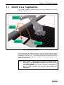
Model Case Application ................................................................................................................................. 1-1
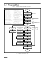
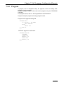
Program Flow ................................................................................................................................................. 1-2
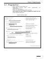
Program List ................................................................................................................................................... 1-3
Chapter 2 Program Flow
2.1
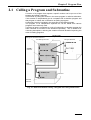
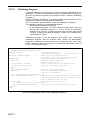
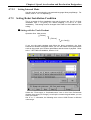
Calling a Program and Subroutine.................................................................................................................. 2-1
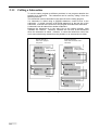
2.1.1 Calling a Subroutine................................................................................................................................... 2-2
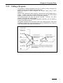
2.1.2 Calling a Program....................................................................................................................................... 2-3
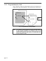
2.1.3 Program Recursive Call ............................................................................................................................. 2-4
2.2
Running a Program......................................................................................................................................... 2-5
2.2.1 Running from the Teach Pendant ............................................................................................................... 2-5
2.2.2 Running from the Operating Panel............................................................................................................. 2-5
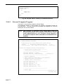
2.2.3 Running from an External Device.............................................................................................................. 2-5
2.3
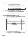
Multitasking.................................................................................................................................................... 2-6
2.3.1 Priority ....................................................................................................................................................... 2-6
2.3.2 Communication among Tasks .................................................................................................................... 2-6
2.4
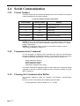
Serial Communication .................................................................................................................................... 2-8
2.4.1 Circuit Number........................................................................................................................................... 2-8
2.4.2 Communication Command......................................................................................................................... 2-8
2.4.3 Clearing the Communication Buffer .......................................................................................................... 2-8
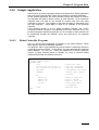
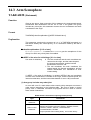
2.4.4 Sample Application .................................................................................................................................... 2-9
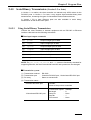
2.4.5 Serial Binary Transmission (Version 1.5 or later) .................................................................................... 2-13
2.5
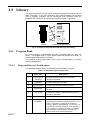
Library.......................................................................................................................................................... 2-14
2.5.1 Program Bank........................................................................................................................................... 2-14
2.5.2 Palletizing Library.................................................................................................................................... 2-15
Chapter 3 Robot Motion
3.1
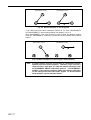
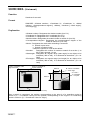
Absolute Motion and Relative Motion ........................................................................................................... 3-1
3.1.1 Absolute Motion......................................................................................................................................... 3-1
3.1.2 Relative Motion.......................................................................................................................................... 3-1
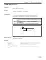
3.1.3 Absolute Motion and Relative Motion Examples ...................................................................................... 3-1
3.2
Confirming Reach Position ............................................................................................................................ 3-3
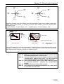
3.2.1 Pass Motion................................................................................................................................................ 3-3
3.2.2 End Motion................................................................................................................................................. 3-3
3.2.3 Encoder Value Check Motion..................................................................................................................... 3-3
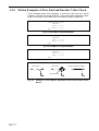
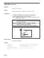
3.2.4 Motion Examples of Pass, End and Encoder Value Check......................................................................... 3-4
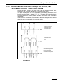
3.2.5 Execution Time Difference among Pass Motion, End Motion and Encoder Value Check Motion ............ 3-5
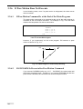
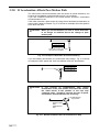
3.2.6 If Pass Motion Does Not Execute .............................................................................................................. 3-6
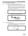
3.2.7 If Pass Motion Effect Reduces ................................................................................................................... 3-7
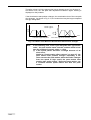
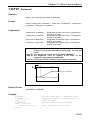
3.2.8 If Acceleration Affects Pass Motion Path................................................................................................... 3-8
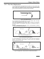
3.2.9 Pass Start Displacement ............................................................................................................................. 3-9
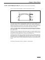
3.2.10 Arch Motion Control [Version 1.9 or later, only for 4-Axis Robot].........................................................3-11
3.3
Interpolation Control .................................................................................................................................... 3-12
3.3.1 PTP Control.............................................................................................................................................. 3-12
3.3.2 CP Control................................................................................................................................................ 3-13
3.3.3 Arc Interpolation Control ......................................................................................................................... 3-13
3.4
If Output Command Is Present after Motion Instruction .............................................................................. 3-14
3.5
Compliance Control Function ...................................................................................................................... 3-15
3.5.1 Overview.................................................................................................................................................. 3-15
3.5.2 Current limiting function for individual axes [V1.2 or later] ................................................................... 3-15
3.5.3 Tip Compliance Control Function [V1.4 or later] .................................................................................... 3-17
Chapter 4 Speed, Acceleration and Deceleration Designation
4.1
External Speed and Internal Speed ................................................................................................................. 4-1
4.2
Speed Designation .......................................................................................................................................... 4-1
4.3
External Acceleration, External Deceleration, Internal Acceleration and Internal Deceleration .................... 4-1
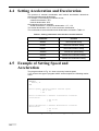
4.4
Setting Acceleration and Deceleration............................................................................................................ 4-2
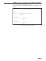
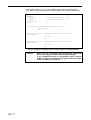
4.5
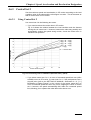
Example of Setting Speed and Acceleration................................................................................................... 4-2
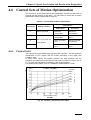
4.6
Control Sets of Motion Optimization ............................................................................................................. 4-5
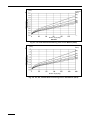
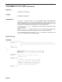
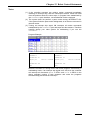
4.6.1 Control Set 0 .............................................................................................................................................. 4-5
4.6.2 Control Set 1 .............................................................................................................................................. 4-8
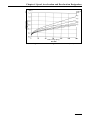
4.6.3 Control Set 2 .............................................................................................................................................. 4-9
4.6.4 Control Set 3 ............................................................................................................................................ 4-10
4.6.5 Using Conditions That You Must Set ....................................................................................................... 4-10
4.6.6 Notes for Setting........................................................................................................................................4-11
4.7
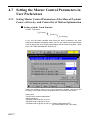
Setting the Master Control Parameters in User Preferences......................................................................... 4-12
4.7.1 Setting Master Control Parameters of the Mass of Payload, Center of Gravity, and Control Set of Motion
Optimization ......................................................................................................................................................... 4-12
4.7.2 Setting Internal Load Condition Values (Mass of Payload and Center of Gravity) and Internal Mode ... 4-16
4.7.3 Setting Robot Installation Condition ........................................................................................................ 4-17
4.7.4 How to Set Optimal Load Capacity Initializing [V1.4 or later] ............................................................... 4-20
4.8
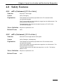
Safety Features ............................................................................................................................................. 4-23
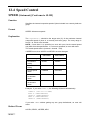
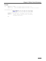
4.8.1 ndTc (Statement) [V1.2 or later] .............................................................................................................. 4-23
4.8.2 ndTs (Statement) [V1.2 or later]............................................................................................................... 4-23
Chapter 5 Vision Control
5.1
Vision Control ................................................................................................................................................ 5-1
5.1.1 Terms of Vision Control ............................................................................................................................. 5-1
PART 2 COMMAND REFERENCE
Chapter 6 Guide to Command Reference
6.1
Description Format of Command Explanations ............................................................................................. 6-1
6.2
Command List ................................................................................................................................................ 6-2
6.2.1 Commands Listed in Alphabetical Order ................................................................................................... 6-2
6.2.2 Commands Listed According to Functions ................................................................................................ 6-2
Chapter 7 PAC Language Configuration Elements
7.1
New Robot Language PAC............................................................................................................................. 7-1
7.2
Relation between PAC Robot Language and Conventional Languages ......................................................... 7-2
7.3
Language Element .......................................................................................................................................... 7-3
7.4
Name .............................................................................................................................................................. 7-3
7.5
Identifier ......................................................................................................................................................... 7-4
7.5.1 Variable ...................................................................................................................................................... 7-4
7.5.2 Function...................................................................................................................................................... 7-8
7.5.3 Label........................................................................................................................................................... 7-8
7.5.4 Program...................................................................................................................................................... 7-9
7.6
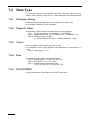
Data Type...................................................................................................................................................... 7-10
7.6.1 Character String........................................................................................................................................ 7-10
7.6.2 Numeric Value.......................................................................................................................................... 7-10
7.6.3 Vector ....................................................................................................................................................... 7-10
7.6.4 Pose .......................................................................................................................................................... 7-10
7.6.5 I/O (ON/OFF)........................................................................................................................................... 7-10
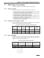
7.7
Data Type Conversion ...................................................................................................................................7-11
7.7.1 Numeric Value...........................................................................................................................................7-11
7.7.2 Character and Numeric Value....................................................................................................................7-11
7.7.3 Pose Type Data..........................................................................................................................................7-11
7.8
Constant........................................................................................................................................................ 7-12
7.8.1 Numeric Value Constant........................................................................................................................... 7-12
7.8.2 Character String Constant ........................................................................................................................ 7-14
7.8.3 Vector Type Constant ............................................................................................................................... 7-14
7.8.4 Pose Constant ........................................................................................................................................... 7-14
7.9
Expression and Operator .............................................................................................................................. 7-16
7.9.1 Assignment Operator................................................................................................................................ 7-16
7.9.2 Arithmetic Operator ................................................................................................................................. 7-16
7.9.3 Relational Operator .................................................................................................................................. 7-17
7.9.4 Logical Operator ...................................................................................................................................... 7-18
7.9.5 Character String Operator ........................................................................................................................ 7-18
7.9.6 Vector Operation ...................................................................................................................................... 7-19
7.9.7 Position Operation.................................................................................................................................... 7-19
7.9.8 Joint Operation ......................................................................................................................................... 7-20
7.9.9 Homogeneous Transformation Array Operation ...................................................................................... 7-20
7.9.10 Operator Precedence (Version 1.5 or later) .............................................................................................. 7-20
7.10 Units for the PAC Language......................................................................................................................... 7-22
Chapter 8 PAC Language Syntax
8.1
Statement and Line ......................................................................................................................................... 8-1
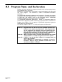
8.2
Program Name and Declaration ..................................................................................................................... 8-2
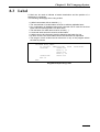
8.3
Label............................................................................................................................................................... 8-3
8.4
Character Set .................................................................................................................................................. 8-4
8.5
Reserved Word ............................................................................................................................................... 8-5
8.6
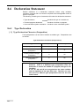
Declaration Statement..................................................................................................................................... 8-6
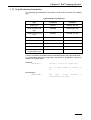
8.6.1 Type Declaration ........................................................................................................................................ 8-6
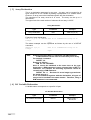
8.6.2 Function/program Declaration ................................................................................................................... 8-9
8.6.3 User Coordinate System Declaration ......................................................................................................... 8-9
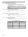
8.7
Assignment Statement .................................................................................................................................. 8-10
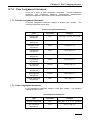
8.7.1 Numeric Value Assignment Statement ..................................................................................................... 8-10
8.7.2 Character String Assignment Statement ................................................................................................... 8-10
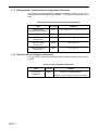
8.7.3 Vector Assignment Statement................................................................................................................... 8-10
8.7.4 Pose Assignment Statement.......................................................................................................................8-11
8.8
Flow Control Statement................................................................................................................................ 8-13
8.8.1 Unconditional Branch .............................................................................................................................. 8-13
8.8.2 Conditional Branch .................................................................................................................................. 8-13
8.8.3 Selection................................................................................................................................................... 8-13
8.8.4 Repeat....................................................................................................................................................... 8-14
8.8.5 Calling Defined Process ........................................................................................................................... 8-15
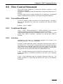
8.9
Robot Control Statement .............................................................................................................................. 8-17
8.9.1 Motion Control Statement ........................................................................................................................ 8-17
8.9.2 Stop Control Statement............................................................................................................................. 8-17
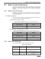
8.9.3 Speed Control Statement .......................................................................................................................... 8-18
8.9.4 Time Control Statement ........................................................................................................................... 8-18
8.9.5 Coordinate Transformation Statement...................................................................................................... 8-18
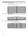
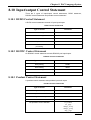
8.10 Input/output Control Statement .................................................................................................................... 8-19
8.10.1 DI/DO Control Statement......................................................................................................................... 8-19
8.10.2 RS232C Control Statement ...................................................................................................................... 8-19
8.10.3 Pendant Control Statement....................................................................................................................... 8-19
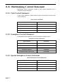
8.11 Multitasking Control Statement.................................................................................................................... 8-20
8.11.1 Task Control Statement ............................................................................................................................ 8-20
8.11.2 Semaphore Control Statement.................................................................................................................. 8-20
8.11.3 Special Semaphore Control Statement ..................................................................................................... 8-20
8.12 Time and Date Control ................................................................................................................................. 8-21
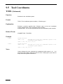
8.13 Error Control ................................................................................................................................................ 8-22
8.14 System Information ...................................................................................................................................... 8-23
8.15 Preprocessor ................................................................................................................................................. 8-24
8.16 Calling with a Value and with Reference...................................................................................................... 8-25
8.16.1 Calling with a Value ................................................................................................................................. 8-25
8.16.2 Calling with Reference............................................................................................................................. 8-26
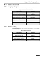
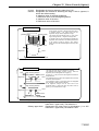
8.17 Vision Control .............................................................................................................................................. 8-27
8.17.1 Image Input/output ................................................................................................................................... 8-27
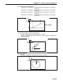
8.17.2 Window Setting........................................................................................................... ............................. 8-27
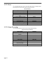
8.17.3 Draw......................................................................................................................................................... 8-28
8.17.4 Image Processing...................................................................................................................................... 8-28
8.17.5 Code Recognition..................................................................................................................................... 8-29
8.17.6 Labeling.................................................................................................................................................... 8-29
8.17.7 Search Function........................................................................................................................................ 8-29
8.17.8 Result Obtaining....................................................................................................................................... 8-30
8.17.9 Vision Calibration .................................................................................................................................... 8-30
Chapter 9 Declaration Statements
9.1
9.2
9.3
9.4
9.5
9.6
9.7
9.8
Program Name................................................................................................................................................ 9-1
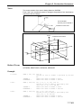
Interference Area Coordinates ........................................................................................................................ 9-2
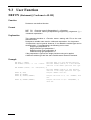
User Function ................................................................................................................................................. 9-4
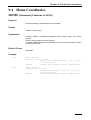
Home Coordinates .......................................................................................................................................... 9-5
Tool Coordinates ............................................................................................................................................ 9-6
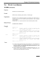
Work Coordinates............................................................................................................ ............................... 9-7
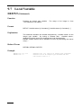
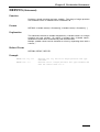
Local Variable................................................................................................................................................. 9-8
Array............................................................................................................................................................. 9-17
Chapter 10 Assignment Statements
10.1
10.2
10.3
10.4
10.5
10.6
10.7
Variables ....................................................................................................................................................... 10-1
Vector ........................................................................................................................................................... 10-2
Figure ........................................................................................................................................................... 10-5
Link Angle.................................................................................................................................................... 10-6
Posture.......................................................................................................................................................... 10-7
Rotation Component..................................................................................................................................... 10-8
Axis Component......................................................................................................................................... 10-12
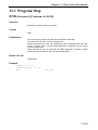
Chapter 11 Flow Control Statements
11.1
11.2
11.3
11.4
11.5
11.6
Program Stop .................................................................................................................................................11-1
Call ................................................................................................................................................................11-4
Repeat............................................................................................................................................................11-9
Conditional Branch......................................................................................................................................11-17
Unconditional Branch..................................................................................................................................11-21
Comment .....................................................................................................................................................11-23
Chapter 12 Robot Control Statements
12.1
12.2
12.3
12.4
12.5
12.6
12.7
12.8
12.9
12.10
Motion Control ............................................................................................................................................. 12-1
Figure Control ............................................................................................................................................ 12-35
Stop Control ............................................................................................................................................... 12-40
Speed Control ............................................................................................................................................. 12-44
Time Control .............................................................................................................................................. 12-60
Coordinate Transformation......................................................................................................................... 12-62
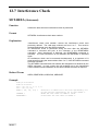
Interference Check...................................................................................................................................... 12-66
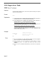
Supervisor Task .......................................................................................................................................... 12-68
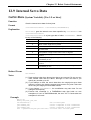
Internal Servo Data..................................................................................................................................... 12-69
Particular Control ....................................................................................................................................... 12-71
Chapter 13 Input/Output Control Statements
13.1 I/O Port......................................................................................................................................................... 13-1
13.2 Command for RS232C and Ethernet (Server/Client) Port............................................................................ 13-8
13.3 Serial Binary Transmission Commands (RS232C and Ethernet ports) ...................................................... 13-13
13.4 Pendant ....................................................................................................................................................... 13-20
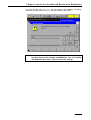
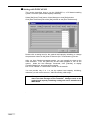
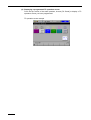
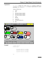
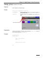
13.5 Customizing TP Operation Screens............................................................................................................ 13-24
13.5.1 Programming a TP operation screen....................................................................................................... 13-25
Chapter 14 Multitasking Control Statements
14.1
14.2
14.3
Task Control ................................................................................................................................................. 14-1
Semaphore .................................................................................................................................................... 14-6
Arm Semaphore.......................................................................................................................................... 14-14
Chapter 15 Functions
15.1
15.2
15.3
15.4
15.5
15.6
15.7
15.8
15.9
15.10
15.11
15.12
15.13
15.14
15.15
Arithmetic Function...................................................................................................................................... 15-1
Trigonometric Function.............................................................................................................................. 15-12
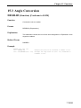
Angle Conversion....................................................................................................................................... 15-19
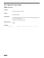
Speed Conversion....................................................................................................................................... 15-22
Time Function ............................................................................................................................................ 15-23
Vector ......................................................................................................................................................... 15-24
Pose Data Type Transformation.................................................................................................................. 15-28
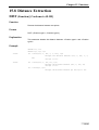
Distance Extraction .................................................................................................................................... 15-35
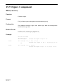
Figure Component ...................................................................................................................................... 15-36
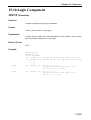
Angle Component....................................................................................................................................... 15-37
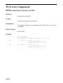
Axis Component......................................................................................................................................... 15-38
Rotation Component................................................................................................................................... 15-41
Figure Component ...................................................................................................................................... 15-45
Position Function........................................................................................................................................ 15-46
Character String Function........................................................................................................................... 15-50
Chapter 16 Constants
16.1
Built-in Constants......................................................................................................................................... 16-1
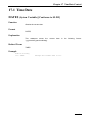
Chapter 17 Time/Date Control
17.1
Time/Date ..................................................................................................................................................... 17-1
Chapter 18 Error Controls
18.1
18.2
Error Information ......................................................................................................................................... 18-1
Error Interruption ......................................................................................................................................... 18-4
Chapter 19 System Information
19.1
19.2
System .......................................................................................................................................................... 19-1
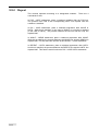
Log ............................................................................................................................................................... 19-4
Chapter 20 Preprocessor
20.1
20.2
20.3
Symbol Constants · Macro Definitions......................................................................................................... 20-1
File Fetch...................................................................................................................................................... 20-4
Optimization................................................................................................................................................. 20-5
Chapter 21 Vision Control (Option)
21.1
21.2
21.3
21.4
21.5
21.6
21.7
21.8
21.9
21.10
Precautions for using vision commands. ...................................................................................................... 21-1
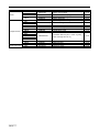
Compatibility with the Conventional µVision-15......................................................................................... 21-1
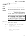
Image Input and Output................................................................................................................................ 21-3
Window Setting .......................................................................................................................................... 21-14
Draw........................................................................................................................................................... 21-24
Vision Processing ....................................................................................................................................... 21-41
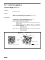
Code Recognition ....................................................................................................................................... 21-64
Labeling...................................................................................................................................................... 21-67
Search Function.......................................................................................................................................... 21-76
Obtaining Results ....................................................................................................................................... 21-93
Chapter 22 Appendices
22.1
22.2
22.3
22.4
22.5
22.6
22.7
22.8
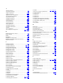
Index
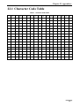
Character Code Table ................................................................................................................................... 22-1
Figures of the Shoulder, Elbow, and Wrist ................................................................................................... 22-2
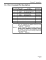
Environment Setting Values ....................................................................................................................... 22-13
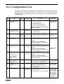
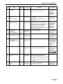
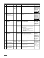
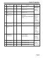
Configuration List ...................................................................................................................................... 22-14
Reserved Word List .................................................................................................................................... 22-21
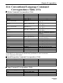
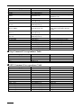
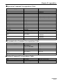
Conventional Language Command Correspondence Table (VS) ............................................................... 22-23
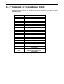
Version Correspondence Table ................................................................................................................... 22-28
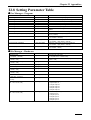
Setting Parameter Table.............................................................................................................................. 22-29
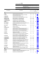
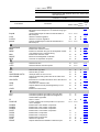
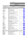
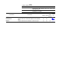
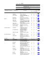
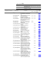
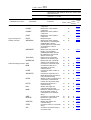
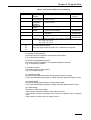
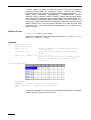
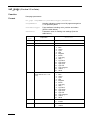
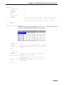
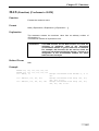
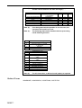
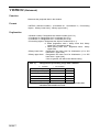
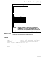
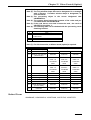
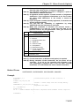
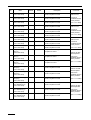
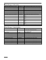
Commands Listed in Alphabetical Order
Vision
4-axis 6-axis device
Commands
¤
¡
¤
¡
¤
¡
¤
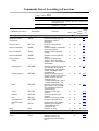
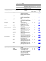
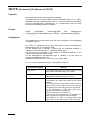
V1.2
Available with all series of robots and vision device.
Available with all series of robots. The command
specifications differ between the 4-axis, 6-axis robot,
and vision device.
Available with the 4-axis robots and the 6-axis robots
of Version 1.2 or later.
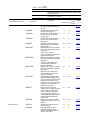
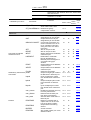
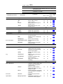
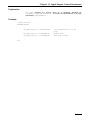
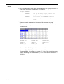
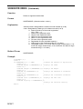
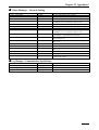
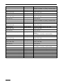
Functions
4-axis 6-axis
Vision
device
Refer
to:
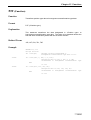
#
#define
#error
#include
#pragma optimize
#undef
Replaces a designated constant or macro name in
the program with a designated character string.
Forcibly generates a compiling error if the #error
command is executed.
Fetches the preprocessor program.
Designates optimization to be executed for each
program.
Makes a symbol constant defined with #define or
macro definition invalid.
¤
¤
¤
20-1
¤
¤
¤
20-3
¤
¤
¤
¤
¤
¤
20-4
20-5
¤
¤
¤
20-2
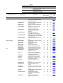
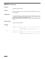
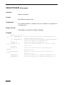
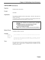
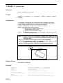
Obtains the absolute value of an expression value.
Designates internal acceleration and internal
deceleration.
Obtains an arc cosine.
Executes the absolute movement designated in the
tool coordinate system.
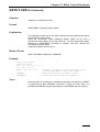
Declares the area where an interference check is
performed.
Returns the center position and direction of a
rectangular parallelepiped with the position type for
an area where an interference check is performed.
Returns the size (each side length) of a rectangular
parallelepiped which defines the interference check
area with the vector type.
Defines the motion ratio relative to the programmed
full travel distance to the target point in order to make
the current program stand by to execute the next step
until the robot reaches the defined motion ratio.
Converts to a character code.
Obtains an arc sine.
Obtains an arc tangent.
Obtains the arc tangent of expression 1 divided by
expression 2.
Extracts an approach vector.
¤
¤
¤
¤
¤
15-1
12-47
¤
¡
¤
¡
¤
15-12
12-1
¡
¡
9-2
¤
¤
15-46
¤
¤
15-47
¤
V1.2
12-32
¤
¤
¤
¤
¤
¤
¤
¤
¤
¤
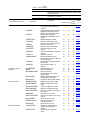
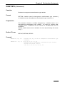
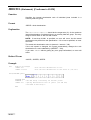
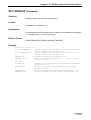
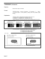
Converts the value of an expression to a binary
character string.
Executes labeling.
Copies an object label number.
Obtains the label number for designated coordinates.
Executes feature measurement of the object label
number.
Sounds a buzzer.
¤
¤
¤
15-51
¤
¤
¤
¤
¤
¤
¤
¤
¤
¤
¤
¤
21-67
21-74
21-72
21-70
¤
¤
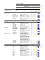
A
ABS
ACCEL
ACOS
APPROACH
AREA
AREAPOS
AREASIZE
ARRIVE
ASC
ASIN
ATN
ATN2
AVEC
¤
¤
¤
¤
15-50
15-13
15-14
15-15
15-24
B
BIN$
BLOB
BLOBCOPY
BLOBLABEL
BLOBMEASURE
BUZZER
13-22
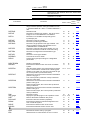
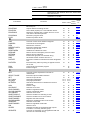
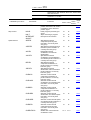
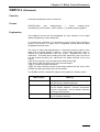
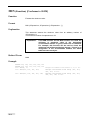
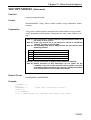
Vision
4-axis 6-axis device
Commands
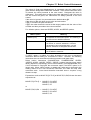
¤
¡
¤
¡
¤
¡
¤
V1.2
Available with all series of robots and vision device.
Available with all series of robots. The command
specifications differ between the 4-axis, 6-axis robot,
and vision device.
Available with the 4-axis robots and the 6-axis robots
of Version 1.2 or later.
Functions
4-axis 6-axis
Vision
device
Refer
to:
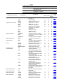
C
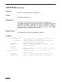
CALL
CAMIN
CAMLEVEL
CAMMODE
change_bCap
change_pCap
CHANGETOOL
CHANGEWORK
CHR$
CLEARLOG
com_discom
com_encom
com_state
COS
CREATESEM
CURACC
CURDEC
CUREXJ
CURFIG
CURJACC
CURJDEC
CUREXTACC
CUREXTDEC
CUREXTSPD
CURJNT
CURJSPD
CURPOS
CURSPD
CURTOOL
CURTRN
CURWORK
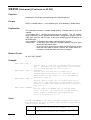
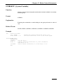
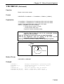
Calls a program and executes it.
Stores an image from the camera in the image
memory (process screen).
Sets the camera image input level.
Sets the function used to store a camera image.
Edits a caption for a specified button.
Edits a caption for a specified page.
Changes the tool coordinate system.
Changes the user coordinate system.
Converts an ASCII code to a character.
Initializes recording of the servo control log.
Releases the RS-232C port from binary transmission.
Enables the RS-232C port only for binary
transmission.
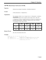
Gets the status of RS-232C or Ethernet port.
Obtains a cosine.
Creates a semaphore.
Gets the current internal composite acceleration of
joints included in a currently held arm group.
Gets the current internal composite deceleration of
joints included in a currently held arm group.
Gets the current angle of an extended-joint into a
floating-point variable.
Obtains the current value of the robot figure.
Gets the current internal acceleration of individual
joints included in a currently held arm group.
Gets the current internal deceleration of individual
joints included in a currently held arm group.
Obtains the current external acceleration value.
Obtains the current external deceleration value.
Obtains the current external speed value.
Obtains the current angle of the robot using type J.
Gets the current internal speed of individual joints
included in a currently held arm group.
Obtains the current position in the tool coordinate
system using type P.
Gets the current internal composite speed of joints
included in a currently held arm group.
Obtains the currently designated TOOL number.
Obtains the current position in the tool coordinate
system using type T.
Obtains the currently designated WORK number.
¤
¤
¤
¤
¤
¤
11-4
21-3
¤
¤
V1.5
V1.5
¤
¤
¤
¤
V1.5
V1.5
¤
¤
V1.5
V1.5
¤
¤
¤
¤
V1.5
V1.5
¤
¤
21-6
21-4
13-32
13-33
12-62
12-63
15-52
19-5
13-18
13-17
V1.5
¤
¤
¤
V1.5
¤
¤
¤
¤
¤
12-53
V1.5
V1.6
12-27
¤
¤
¤
¤
12-35
12-52
¤
¤
12-54
V1.4
V1.4
V1.4
¡
¤
V1.4
V1.4
V1.4
¡
¤
12-57
12-58
12-59
12-24
12-55
¡
¡
12-25
¤
¤
12-56
V1.4
¤
V1.4
¤
12-64
12-26
V1.4
V1.4
12-65
¤
¤
¤
¤
17-1
12-49
¤
¤
¤
¤
13-19
15-16
14-7
12-51
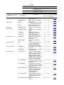
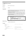
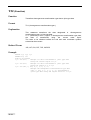
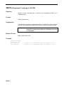
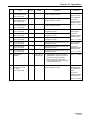
D
DATE$
DECEL
DEF FN
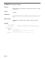
Obtains the current date.
Specifies the internal composite deceleration of joints
involved in a currently held arm group.
Declares a user-defined function.
¤
9-4
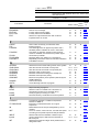
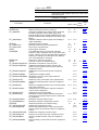
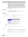
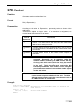
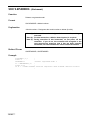
Vision
4-axis 6-axis device
Commands
DEFDBL
DEFEND
DEFINT
DEFIO
DEFJNT
DEFPOS
DEFSNG
DEFSTR
DEFTRN
DEFVEC
DEGRAD
DELAY
DELETESEM
DEPART
DESTEXJ
DESTJNT
DESTPOS
DESTTRN
DIM
disp_page
DIST
DO-LOOP
DRAW
DRIVE
DRIVEA
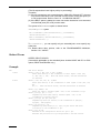
¤
¡
¤
¡
¤
¡
¤
V1.2
Available with all series of robots and vision device.
Available with all series of robots. The command
specifications differ between the 4-axis, 6-axis robot,
and vision device.
Available with the 4-axis robots and the 6-axis robots
of Version 1.2 or later.
Functions
4-axis 6-axis
Vision
device
Refer
to:
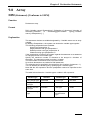
Declares a double precision real type variable. The
range of double precision real type variables is from 1.79769313486231D + 308 to 1.79769313486231D +
308.
Defends a task.
Declares an integer type variable. The range of the
integer is from -2147483648 to 2147483647.
Declares an I/O variable corresponding to the
input/output port.
Declares a joint type variable.
Declares a position type variable.
Declares a single precision real type variable. The
range of single precision real variables is from 3.402823E+38 to 3.402823E+38.
Declares a character string type variable. You can
enter 247 characters or less as a character string.
Declares a homogeneous transformation type
variable.
Declares a vector type variable.
Converts the unit to a radian.
Suspends program processing for a designated
period time.
¤
¤
¤
9-10
¤
¤
¤
¤
¤
14-4
9-8
¤
¤
¤
9-16
¡
¡
¤
¡
¡
¤
¤
9-14
9-13
9-9
¤
¤
¤
9-11
¤
¤
¤
¤
¤
¤
¤
¤
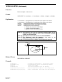
Deletes a semaphore.
Executes the relative motion in the tool coordinate
system.
Gets the target position of an extended-joint invoked
by the current motion command into a floating-point
variable. If the robot is on halt, this command will get
the current position (commanded value).
Obtains the current movement instruction destination
position using type J.
The current position (instruction value) is obtained
when the robot stops.
Obtains the current movement instruction destination
position with type P.
When the robot stops, the current value (instruction
value) is obtained.
Obtains the current movement instruction destination
position with type T.
When the robot stops, the current position (instruction
value) is obtained.
Declares an array.
Displays a specified page of a TP operation screen.
Returns the distance between two points.
Executes a decision iteration (repetition).
Executes the relative movement designated in the
work coordinate system.
Executes the relative motion of each axis.
Executes the absolute motion of each axis.
¤
¡
¤
¡
14-10
12-4
V1.5
V1.6
12-31
¡
¡
12-28
¡
¡
12-29
¤
¤
12-30
¤
V1.5
¡
¤
¤
¤
V1.5
¡
¤
¤
¤
¤
¤
¤
¤
¤
¤
¤
9-15
¤
¤
¤
¤
9-12
15-19
12-60
9-17
13-34
15-35
11-9
12-7
12-9
12-11
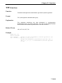
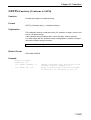
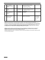
E
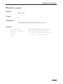
END
ERL
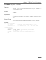
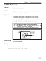
Declares the motion end by a program.
Obtains the line number where an error occurred.
¤
11-1
18-1
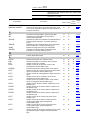
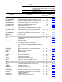
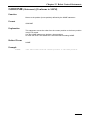
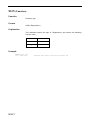
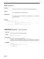
Vision
4-axis 6-axis device
Commands
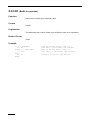
ERR
ERRMSG$
EXIT DO
EXIT FOR
EXP
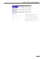
¤
¡
¤
¡
¤
¡
¤
V1.2
Available with all series of robots and vision device.
Available with all series of robots. The command
specifications differ between the 4-axis, 6-axis robot,
and vision device.
Available with the 4-axis robots and the 6-axis robots
of Version 1.2 or later.
Functions
4-axis 6-axis
Vision
device
Refer
to:
Obtains an error number that occurred.
Sets an error message.
Forcibly exits from DO-LOOP.
Forcibly exits from FOR-NEXT.
Obtains an exponential function with a natural
logarithm taken as a base.
¤
¤
¤
¤
¤
¤
¤
¤
¤
¤
Sets a value of false (0) to a Boolean value.
Extracts a figure.
Calculates figures at an approach position and a
standard position available to move in CP motion.
Calculates an approach position where the PTP
motion is available, and a reference position figure.
Clears the input buffer.
Releases tasks from waiting for a semaphore.
Repeatedly executes a series of instructions between
FOR-NEXT sections.
¤
¡
¡
¤
¡
¡
¡
¡
¤
¤
¤
¤
¤
¤
¤
Obtains the environment setting values of the system.
Gets the internal servo data of robot joints.
Gets the internal servo data of a specified joint.
Releases robot control priority.
Releases a task from waiting for a semaphore.
Releases visual process priority.
Moves to the position (home position) defined by the
HOME statement.
Calls a subroutine.
Unconditionally branches a program.
¤
V1.5
V1.5
¤
¤
¤
¤
¤
V1.5
V1.5
¤
¤
¤
¤
¤
19-1
12-69
12-70
14-19
14-12
14-21
12-13
¤
¤
¤
¤
¤
¤
11-6
11-21
Stops executing a program.
Obtains a value converted from a decimal to a
hexadecimal number as a character string.
Holds program processing for a time.
Declares arbitrary coordinates as a home position.
¤
¤
¤
¤
¤
12-41
15-56
¤
¡
¤
¡
Conditionally decides a conditional expression
between IF-END IF.
Executes a conditional decision of a logical
expression.
Reads data from the I/O port designated by an I/O
variable.
Turns on motors, carrier out CAL, and sets the speed
according to the preset supervisor task parameters.
Obtains data from the RS232C or Ethernet port.
Inputs a single byte of data from the RS-232C or
Ethernet port.
Obtains the maximum integer value possible from a
designated value.
¤
¤
¤
11-17
¤
¤
¤
11-18
¤
¤
¤
13-1
V1.7
V1.7
¤
V1.5
¤
V1.5
¤
13-8
13-14
¤
¤
¤
15-3
¤
¤
¤
¤
18-2
18-3
11-11
11-14
15-2
F
FALSE
FIG
FIGAPRL
FIGAPRP
FLUSH
FLUSHSEM
FOR-NEXT
¤
16-4
15-36
12-37
12-39
¤
13-12
14-11
11-12
G
GETENV
GetSrvData
GetJntData
GIVEARM
GIVESEM
GIVEVIS
GOHOME
GOSUB
GOTO
H
HALT
HEX$
HOLD
HOME
12-40
9-5
I
IF-END IF
IF-THEN-ELSE
IN
INIT
INPUT
inputb
INT
12-68
Vision
4-axis 6-axis device
Commands
INTERRUPT ON/OFF
IOBLOCK ON/OFF
¤
¡
¤
¡
¤
¡
¤
V1.2
Available with all series of robots and vision device.
Available with all series of robots. The command
specifications differ between the 4-axis, 6-axis robot,
and vision device.
Available with the 4-axis robots and the 6-axis robots
of Version 1.2 or later.
Functions
4-axis 6-axis
Vision
device
Refer
to:
Interrupts a robot motion.
Concurrently executes a non-motion instruction such
as an I/O or calculation instruction during execution of
a motion instruction.
¤
¤
¤
¤
12-42
13-3
Transforms joint type data to position type data.
Transforms joint type data to homogeneous
transformation type data.
Specifies the internal acceleration and deceleration of
individual joints included in a currently held arm
group.
Specifies the internal deceleration ratio of individual
joints included in a currently held arm group.
Extracts an angle from joint type coordinates.
Specifies the internal speed of individual joints
included in a currently held arm group.
¡
¡
¡
¡
15-28
15-29
¤
¤
12-48
¤
¤
12-50
¡
¤
¡
¤
15-37
12-46
Forcibly terminates a task.
¤
¤
14-2
Extracts the left part of a character string.
Obtains the length of a character string in bytes.
Assigns a value to a variable.
Assigns a value to an approach vector of the
homogeneous transformation type.
Sets the environment setting values of the system.
Assigns a value to a figure component of the position
type or homogenous transformation type.
Assigns a value to a designated link angle of the joint
type.
Assigns a value to an orientation vector of the
homogeneous transformation type.
Assigns a value to a position vector of the position
type or homogenous transformation type.
Assigns a value to three rotation components of the
position type.
Assigns a value to the X axis rotation component of
the position type.
Assigns a value to the Y axis rotation component of
the position type.
Assigns a value to the Z axis rotation component of
the position type.
Assigns a value to the T axis component of the
position type.
Assigns a value to the X axis component of the
Vector type/ Position type/ Homogenous
transformation type.
Assigns a value to the Y axis component of the
Vector type/ Position type/ Homogenous
transformation type.
Assigns a value to the Z axis component of the vector
type/ position type/ homogeneous transformation
type.
¤
¤
¡
¤
¤
¡
¤
¤
¤
¡
15-57
15-58
10-1
10-2
¤
¤
¤
¤
¤
19-2
10-5
¤
¤
10-6
¤
¤
10-3
¤
¤
10-4
¤
10-7
¤
10-8
¤
10-9
¤
10-10
J
J2P
J2T
JACCEL
JDECEL
JOINT
JSPEED
K
KILL
L
LEFT$
LEN
LET
LETA
LETENV
LETF
LETJ
LETO
LETP
LETR
LETRX
LETRY
LETRZ
LETT
LETX
LETY
LETZ
¤
10-11
¤
¤
10-12
¤
¤
10-13
¤
¤
10-14
Vision
4-axis 6-axis device
Commands
LINEINPUT
linputb
LOG
LOG10
lprintb
¤
¡
¤
¡
¤
¡
¤
V1.2
Available with all series of robots and vision device.
Available with all series of robots. The command
specifications differ between the 4-axis, 6-axis robot,
and vision device.
Available with the 4-axis robots and the 6-axis robots
of Version 1.2 or later.
Functions
4-axis 6-axis
Vision
device
¤
¤
V1.5
V1.5
¤
¤
V1.5
¤
¤
V1.5
Obtains the vector size.
Extracts the maximum value.
Extracts a character string for the designated number
of characters from a character string.
Extracts the minimum value.
Moves to the designated coordinate.
Converts an expression of speed.
¤
¤
¤
¤
¤
¤
¤
¡
¤
¤
¡
¤
Sets the TC time.
Sets the TS time and slow speed.
¤
¤
V1.2
V1.2
Sets an OFF (0) value.
Sets an ON (1) value.
Interrupts when an error occurs.
Calls a corresponding subroutine to the value of an
expression.
Executes an unconditional branch due to the value of
an expression.
Converts to a character code.
Outputs data to the I/O port designated by an I/O
variable.
Extracts an orient vector.
¤
¤
¤
¤
¤
¤
¤
¤
¤
¤
¤
16-1
16-2
18-4
11-7
¤
¤
¤
11-22
¤
¤
¤
¤
¤
¤
15-60
13-2
¤
¤
15-25
Transforms position type data to joint type data.
Transforms position type data to homogeneous
transformation type data.
Sets a π value.
Forcibly restores the current position of a joint to 0
mm or 0 degree.
Extracts the X-axis rotation component.
Extracts the Y-axis rotation component.
Extracts the Z-axis rotation component.
Extracts the T-axis rotation component.
Extracts the X-component.
Extracts the Y-component.
Extracts the Z-component.
Obtains an exponent.
Outputs data from the RS232C or Ethernet port.
¡
¡
¡
¡
15-30
15-31
¤
V1.5
¤
V1.6
Reads data to a delimiter through the RS232C or
Ethernet port and assigns it to a character string type
variable.
Inputs multiple bytes of data from the RS-232C or
Ethernet port.
Obtains a natural logarithm.
Obtains a common logarithm.
Outputs multiple bytes of data to the RS-232C or
Ethernet port.
¤
Refer
to:
13-9
13-16
¤
¤
15-4
15-5
13-15
M
MAGNITUDE
MAX
MID$
MIN
MOVE
MPS
¤
¤
¤
15-27
15-7
15-59
15-8
12-14
15-22
N
ndTC
ndTS
4-23
4-23
O
OFF
ON
ON ERROR GOTO
ON-GOSUB
ON-GOTO
ORD
OUT
OVEC
P
P2J
P2T
PI
POSCLR
POSRX
POSRY
POSRZ
POST
POSX
POSY
POSZ
POW
PRINT
¤
¤
¤
¤
¤
¡
¡
¡
¤
¤
¡
¡
¡
¤
¤
¤
¤
16-3
12-34
15-41
15-42
15-43
15-44
15-38
15-39
15-40
15-6
13-10
Vision
4-axis 6-axis device
Commands
printb
PRINTDBG
PRINTLBL
PRINTMSG
PROGRAM
PVEC
¤
¡
¤
¡
¤
¡
¤
V1.2
Available with all series of robots and vision device.
Available with all series of robots. The command
specifications differ between the 4-axis, 6-axis robot,
and vision device.
Available with the 4-axis robots and the 6-axis robots
of Version 1.2 or later.
Functions
Outputs a single byte of data to the RS-232C or
Ethernet port.
Outputs data to the debug window.
Sets a label (caption) for a user definition button.
Displays a message with a caption and icon on the
color LCD of the teach pendant.
Declares a program name.
Extracts a position vector.
4-axis 6-axis
Vision
device
Refer
to:
V1.5
V1.5
13-13
¤
¤
¤
¤
¤
¤
13-21
13-23
13-20
¤
¡
¤
¡
¤
9-1
15-26
Converts a value set in radians to degrees.
Converts the unit to degrees.
Describes a comment.
Executes a tail decision iteration.
Sets an I/O port to OFF.
Initializes an interference check.
Returns from an interruption process routine.
Returns from a subroutine.
Extracts the right part of a character string.
Generates random numbers from 0 to 1.
Executes a rotation movement around the designated
axis.
Executes rotary motion by taking an approach vector
as an axis.
Concurrently runs another program.
Extracts a figure.
¤
¤
¤
¤
¤
¤
¤
¤
¤
¤
¡
¤
¤
¤
¤
¤
¤
¤
¤
¤
¤
¡
¤
¤
¤
¤
¤
15-20
15-21
11-23
11-15
13-7
12-67
18-5
11-8
15-61
15-9
12-19
¤
¤
12-22
¤
¤
¤
14-1
15-45
Converts a value expressed in seconds to
milliseconds.
Executes a plural condition decision.
Sets an I/O port to ON.
Sets button parameters.
Sets page parameters.
Selects the area where an interference check is
performed.
Checks a sign.
Searches for a circle.
Deletes a registered model.
Copies a registered model.
Searches for a corner.
Sets the condition for searching a circle.
Sets the conditions for a corner search.
Registers the search model.
Displays a registered model on the screen.
Searches for a model.
Refers to registered model data.
Obtains a sine.
Specifies the internal composite speed of joints
included in a currently held arm group.
Converts an expression to a designated format and
returns it as a character string.
¤
¤
¤
15-23
¤
¤
V1.5
V1.5
¤
¤
¤
V1.5
V1.5
¤
¤
¤
11-19
13-5
13-27
13-30
12-66
¤
¤
¤
¤
¤
¤
¤
¤
¤
¤
¤
¤
¤
¤
¤
¤
¤
¤
¤
¤
¤
¤
¤
¤
¤
¤
¤
¤
¤
¤
¤
¤
¤
¤
¤
¤
¤
¤
15-10
21-90
21-80
21-79
21-87
21-89
21-86
21-76
21-81
21-82
21-78
15-17
12-44
¤
¤
¤
15-53
R
RAD
RADDEG
REM
REPEAT-UNTIL
RESET
RESETAREA
RESUME
RETURN
RIGHT$
RND
ROTATE
ROTATEH
RUN
RVEC
¤
¤
¤
S
SEC
SELECT CASE
SET
set_button
set_page
SETAREA
SGN
SHCIRCLE
SHCLRMODEL
SHCOPYMODEL
SHCORNER
SHDEFCIRCLE
SHDEFCORNER
SHDEFMODEL
SHDISPMODEL
SHMODEL
SHREFMODEL
SIN
SPEED
SPRINTF$
Vision
4-axis 6-axis device
Commands
SQR
STARTLOG
ST_aspACLD
ST_aspChange
STATUS
ST_OffSrvLock
ST_OnSrvLock
STOP
STOPEND
STOPLOG
STR$
ST_ResetCompControl
ST_ResetCompEralw
ST_ResetCompJLimit
ST_ResetCompRate
ST_ResetCompVMode
ST_ResetCurLmt
ST_ResetDampRate
ST_ResetEralw
ST_ResetFrcAssist
ST_ResetFrcLimit
ST_ResetGravity
ST_ResetGrvOffset
ST_ResetZBalance
STRPOS
ST_SetCompControl
ST_SetCompEralw
ST_SetCompFControl
ST_SetCompJLimit
ST_SetCompRate
ST_SetCompVMode
¤
¡
¤
¡
¤
¡
¤
V1.2
Available with all series of robots and vision device.
Available with all series of robots. The command
specifications differ between the 4-axis, 6-axis robot,
and vision device.
Available with the 4-axis robots and the 6-axis robots
of Version 1.2 or later.
Functions
Obtains the square root.
Starts recording of the servo control log.
Changes the internal load condition values. There are
the mass of payload, noted in grams (g), and the
payload center of gravity, noted in millimeters (mm), for
the load condition values. Designate both of them. (See
Note1.)
Selects the internal mode for proper control setting of
motion optimization.
Obtains the program status.
Releases servo lock for the specified axis.
Servo-locks a specified axis.
Ends program execution.
This statement stops a continuously executed
program or stops a program with a cycle option after
a cycle. When a cycle of a program that includes this
statement is started, the motion will not be affected
even if this statement is executed.
Stops servo control log recording.
Converts a value to a character string.
Disables the compliance control function.
Initializes the allowable deviation values of the
position and the posture of the tool end under the
compliance control.
Initializes the current limit under the compliance
control.
Initializes the compliance rates.
Disables the velocity control mode under the
compliance control.
Resets the motor current limit of the specified axis.
Initializes the damping rates under the compliance
control.
Resets the allowable deviation value of the specified
axis to the initial value.
Initializes the force assistance (special compliance
control function statement).
Initializes the force limiting rates.
Disables the balance setting between the limited
motor torque and gravity torque, which is made with
ST_SetGravity.
Disables the gravity offset function.
Disables the gravity compensation function.
Obtains the position of a character string.
Enables the compliance function.
Sets the allowable deviation values of the position
and the posture of the tool tip under the compliance
control.
Enables the compliance control function.
Sets the current limit under the compliance control.
Sets the compliance rates under the compliance
control.
Sets the velocity control mode under the compliance
control.
4-axis 6-axis
Vision
device
¤
¤
V1.9
¤
¤
V1.9
V1.9
V1.9
12-72
¤
V1.9
V1.9
¤
¤
¤
14-5
12-83
12-82
11-2
11-3
¤
¤
¤
¤
V1.9
V1.9
¤
¤
¤
Refer
to:
¤
¤
15-11
19-4
12-71
19-6
15-63
12-87
12-100
V1.9
12-96
V1.9
V1.9
12-92
12-98
V1.9
V1.9
V1.9
12-79
12-102
V1.9
V1.9
12-81
V1.9
12-94
V1.9
V1.9
12-90
12-74
V1.9
12-76
12-104
15-62
12-84
12-99
V1.9
V1.9
V1.9
¤
¤
V1.9
V1.9
¤
V1.9
V1.9
V1.9
12-86
12-95
12-91
V1.9
12-97
Vision
4-axis 6-axis device
Commands
ST_SetCurLmt
ST_SetDampRate
ST_SetEralw
ST_SetFrcAssist
ST_SetFrcCoord
ST_SetFrcLimit
ST_SetGravity
ST_SetGrvOffset
ST_SetZBalance
SUSPEND
¤
¡
¤
¡
¤
¡
¤
V1.2
Available with all series of robots and vision device.
Available with all series of robots. The command
specifications differ between the 4-axis, 6-axis robot,
and vision device.
Available with the 4-axis robots and the 6-axis robots
of Version 1.2 or later.
Functions
Sets the limit of motor current to be applied to the
specified axis.
Sets the damping rates under the compliance control.
Modifies the allowable deviation of the specified axis.
Sets the force assistance under the compliance
control.
Selects a force limiting coordinate system.
Sets the force limiting rates.
Compensates for the static load (gravity torque)
applied to each joint and attains balance with gravity
torque.
Compensates the torque of each joint programmed
with ST_SetGravity for gravity torque.
Sets the gravity compensation value of the Z and T
axes (exclusively designed for 4-axis robots).
Suspends a task.
4-axis 6-axis
Vision
device
Refer
to:
V1.9
V1.9
12-77
V1.9
V1.9
V1.9
V1.9
12-101
12-80
12-93
V1.9
V1.9
V1.9
V1.9
12-88
12-89
12-73
V1.9
V1.9
12-75
V1.9
12-103
¤
¤
14-3
Transforms homogeneous transformation type data to
joint type data.
Transforms homogeneous transformation type data to
position type data.
Gets an arm group. Upon execution of this statement,
the programmed speed, acceleration and
deceleration will be set to 100. If the gotten arm
group includes any robot joint, this statement restores
the tool coordinates and work coordinates to the
origin.
Obtains a semaphore with a designated semaphore
ID.
Obtains visual process priority.
Obtains a tangent.
Obtains the current time.
Obtains the elapsed time.
Calculates an inverse matrix of homogeneous
transformation type data.
Declares a tool coordinate system.
Returns a tool coordinate system as the position type.
Sets a value of true (1) to a Boolean value.
¤
¤
15-32
¤
¤
15-33
¤
¤
14-14
¤
¤
14-13
¤
¤
¤
¤
¤
¤
¤
¤
¤
¤
¡
¤
¤
¡
¤
¤
¤
9-6
15-48
16-5
Converts a character string to a numeric value.
Obtains the version of each module.
Binarizes the screen.
Displays a binarized screen.
Designates a drawing brightness value.
Displays an image from the camera on the monitor.
Draws a circle on the screen.
Fill (cleens) a designated screen, set in a mode with
a designated brightness.
Copies the screen.
Draws a cross symbol on the screen.
¤
¤
¤
¤
¤
¤
¤
¤
¤
¤
¤
¤
¤
¤
¤
¤
¤
¤
¤
¤
¤
¤
¤
¤
15-64
19-3
21-47
21-49
21-26
21-7
21-33
21-27
¤
¤
¤
¤
¤
¤
21-54
21-36
T
T2J
T2P
TAKEARM
TAKESEM
TAKEVIS
TAN
TIME$
TIMER
TINV
TOOL
TOOLPOS
TRUE
¤
14-20
15-18
17-2
17-3
15-34
V
VAL
VER$
VISBINA
VISBINAR
VISBRIGHT
VISCAMOUT
VISCIRCLE
VISCLS
VISCOPY
VISCROSS
Vision
4-axis 6-axis device
Commands
VISDEFCHAR
VISDEFTABLE
VISEDGE
VISELLIPSE
VISFILTER
VISGETNUM
VISGETP
VISGETSTR
VISHIST
VISLEVEL
VISLINE
VISLOC
VISMASK
VISMEASURE
VISOVERLAY
VISPLNOUT
VISPOSX
VISPOSY
VISPRINT
VISPROJ
VISPTP
VISPUTP
VISREADQR
VISRECT
VISREFCAL
VISREFHIST
VISREFTABLE
VISSCREEN
VISSECT
VISSTATUS
VISWORKPLN
¤
¡
¤
¡
¤
¡
¤
V1.2
Available with all series of robots and vision device.
Available with all series of robots. The command
specifications differ between the 4-axis, 6-axis robot,
and vision device.
Available with the 4-axis robots and the 6-axis robots
of Version 1.2 or later.
Functions
4-axis 6-axis
Vision
device
Refer
to:
Designates the size of characters and the display
method.
Reads images on the camera and sets the look-up
table data for image output.
Measures the edge in a window.
Draws an ellipse on the screen.
Executes filtering on the screen.
Obtains an image process result from the storage
memory.
Obtains designated coordinate brightness from the
storage memory (processing screen).
Obtains code recognition result.
Obtains the histogram (brightness distribution) of the
screen.
Obtains a binarization level based on the histogram
result.
Draws a line on the screen.
Designates the display position of characters.
Executes calculations between images.
Measures features in the window (area, center of
gravity, main axis angle).
Displays draw screen information on the monitor.
Displays an image in the storage memory on the
monitor.
Obtains an image process result (Coordinate X) from
the storage memory.
Obtains an image process result (Coordinate Y) from
the storage memory.
Displays characters and figures on the screen.
Measures the projected data in the window.
Draws a line connecting two points on the screen.
Draws a point on the screen.
Reads the QR code.
Draws a rectangle on the screen.
Obtains calibration data (Vision-robot coordinate
transformation).
Reads histogram results.
Refers to data on the look-up table.
Designates a drawing screen.
Draws a sector on the screen.
Monitors the process result of each instruction.
Designates the storage memory (process screen) to
process.
¤
¤
¤
21-39
¤
¤
¤
21-11
¤
¤
¤
¤
¤
¤
¤
¤
¤
¤
¤
¤
21-60
21-34
21-50
21-93
¤
¤
¤
21-42
¤
¤
¤
¤
¤
¤
21-94
21-43
¤
¤
¤
21-45
¤
¤
¤
¤
¤
¤
¤
¤
¤
¤
¤
¤
21-30
21-37
21-52
21-55
¤
¤
¤
¤
¤
¤
21-9
21-8
¤
¤
¤
21-95
¤
¤
¤
21-96
¤
¤
¤
¤
¤
¤
¤
¤
¤
¤
¤
¤
¤
¤
¤
¤
¤
¤
¤
¤
¤
21-40
21-58
21-31
21-29
21-64
21-32
21-98
¤
¤
¤
¤
¤
¤
¤
¤
¤
¤
¤
¤
¤
¤
¤
¤
¤
¤
21-44
21-13
21-24
21-35
21-97
21-41
Stops program processing based on a condition.
Executes a head decision iteration.
Deletes set window information.
Copies window data.
Draws a designated window.
Designates an area for image processing.
Obtains window information.
¤
¤
¤
¤
¤
¤
¤
¤
¤
¤
¤
¤
¤
¤
¤
¤
¤
¤
¤
¤
12-61
11-16
21-19
21-20
21-23
21-14
21-22
W
WAIT
WHILE-WEND
WINDCLR
WINDCOPY
WINDDISP
WINDMAKE
WINDREF
Vision
4-axis 6-axis device
Commands
WORK
WORKPOS
WRITE
¤
¡
¤
¡
¤
¡
¤
V1.2
Available with all series of robots and vision device.
Available with all series of robots. The command
specifications differ between the 4-axis, 6-axis robot,
and vision device.
Available with the 4-axis robots and the 6-axis robots
of Version 1.2 or later.
Functions
Declares a user coordinate system.
Returns the user coordinate system as the position
type.
Outputs data from the RS232C or Ethernet port.
4-axis 6-axis
¡
¤
¡
¤
¤
¤
Vision
device
Refer
to:
9-7
15-49
¤
13-11
Commands Listed According to Functions
Vision
4-axis 6-axis device
¤
¤
¤ Available with all series of robots and vision device.
¡
¡
¡ Available with all series of robots. The command
specifications differ between the 4-axis, 6-axis robot,
and vision device.
Available with the 4-axis robots and the 6-axis robots
¤
V1.2
of Version 1.2 or later.
Classified by functions
Commands
Declaration Statements
Program Name
Interference Area
Coordinates
PROGRAM
AREA
User Function
DEF FN
Home Coordinates
HOME
Tool Coordinates
TOOL
Work Coordinates
WORK
Local Variable
Integer
DEFINT
Floating-point
DEFSNG
Double-precision
DEFDBL
String
DEFSTR
Vector
DEFVEC
Position
DEFPOS
Joint
Homogeneous
transform matrix
I/O
DEFJNT
DEFTRN
Array
Assignment Statements
Variables
Vector
DEFIO
DIM
LET
LETA
Functions
4-axis 6-axis
Vision
device
Refer
to:
Declares a program name.
Declares the area where an
interference check is
performed.
Declares a user-defined
function.
Declares arbitrary coordinates
as a home position.
Declares a tool coordinate
system.
Declares a user coordinate
system.
Declares an integer type
variable. The range of the
integer is from -2147483648 to
2147483647.
Declares a single precision real
type variable. The range of
single precision real variables
is from -3.402823E+38 to
3.402823E+38.
Declares a double precision
real type variable. The range of
double precision real type
variables is from 1.79769313486231D + 308 to
1.79769313486231D + 308.
Declares a character string
type variable. You can enter
247 characters or less as a
character string.
Declares a vector type
variable.
Declares a position type
variable.
Declares a joint type variable.
Declares a homogeneous
transformation type variable.
Declares an I/O variable
corresponding to the
input/output port.
Declares an array.
¤
¡
¤
¡
¤
9-1
9-2
¤
¤
¤
9-4
¡
¡
9-5
¡
¡
9-6
¡
¡
9-7
¤
¤
¤
9-8
¤
¤
¤
9-9
¤
¤
¤
9-10
¤
¤
¤
9-11
¤
¤
9-12
¡
¡
9-13
¡
¤
¡
¤
9-14
9-15
¤
¤
¤
9-16
¤
¤
¤
9-17
Assigns a value to a variable.
Assigns a value to an
approach vector of the
homogeneous transformation
type.
¡
¡
¤
¡
10-1
10-2
Vision
4-axis 6-axis device
¤
¡
¤
¡
¤
¡
¤
V1.2
Available with all series of robots and vision device.
Available with all series of robots. The command
specifications differ between the 4-axis, 6-axis robot,
and vision device.
Available with the 4-axis robots and the 6-axis robots
of Version 1.2 or later.
Functions
Classified by functions
Commands
LETO
LETP
Figure
LETF
Link Angle
LETJ
Posture
LETR
Rotation Component
LETRX
LETRY
LETRZ
LETT
Axis Component
LETX
LETY
LETZ
Flow Control Statements
Program Stop
END
STOP
STOPEND
4-axis 6-axis
Vision
device
Refer
to:
Assigns a value to an
orientation vector of the
homogeneous transformation
type.
Assigns a value to a position
vector of the position type or
homogenous transformation
type.
Assigns a value to a figure
component of the position type
or homogenous transformation
type.
Assigns a value to a
designated link angle of the
joint type.
Assigns a value to three
rotation components of the
position type.
Assigns a value to the X axis
rotation component of the
position type.
Assigns a value to the Y axis
rotation component of the
position type.
Assigns a value to the Z axis
rotation component of the
position type.
Assigns a value to the T axis
component of the position type.
Assigns a value to the X axis
component of the Vector type/
Position type/ Homogenous
transformation type.
Assigns a value to the Y axis
component of the Vector type/
Position type/ Homogenous
transformation type.
Assigns a value to the Z axis
component of the vector type/
position type/ homogeneous
transformation type.
¤
¤
10-3
¤
¤
10-4
¤
¤
10-5
¤
¤
10-6
¤
10-7
¤
10-8
¤
10-9
¤
10-10
Declares the motion end by a
program.
Ends program execution.
This statement stops a
continuously executed program
or stops a program with a cycle
option after a cycle. When a
cycle of a program that
includes this statement is
started, the motion will not be
affected even if this statement
is executed.
¤
10-11
¤
¤
10-12
¤
¤
10-13
¤
¤
10-14
¤
¤
¤
11-1
¤
¤
¤
¤
¤
11-2
11-3
Vision
4-axis 6-axis device
Classified by functions
Call
¤
¡
¤
¡
¤
V1.2
Commands
CALL
GOSUB
ON-GOSUB
Repeat
RETURN
DO-LOOP
EXIT DO
FOR-NEXT
EXIT FOR
REPEAT-UNTIL
WHILE-WEND
Conditional Branch
IF-END IF
IF-THEN-ELSE
SELECT CASE
Unconditional Branch
GOTO
ON-GOTO
Comment
REM
Robot Control Statements
Motion Control
APPROACH
DEPART
DRAW
DRIVE
DRIVEA
GOHOME
MOVE
ROTATE
¤
¡
Available with all series of robots and vision device.
Available with all series of robots. The command
specifications differ between the 4-axis, 6-axis robot,
and vision device.
Available with the 4-axis robots and the 6-axis robots
of Version 1.2 or later.
Functions
4-axis 6-axis
Vision
device
Refer
to:
Calls a program and executes
it.
Calls a subroutine.
Calls a corresponding
subroutine to the value of an
expression.
Returns from a subroutine.
Executes a decision iteration
(repetition).
Forcibly exits from DO-LOOP.
Repeatedly executes a series
of instructions between FORNEXT sections.
Forcibly exits from FOR-NEXT.
Executes a tail decision
iteration.
Executes a head decision
iteration.
Conditionally decides a
conditional expression
between IF-END IF.
Executes a conditional
decision of a logical
expression.
Executes a plural condition
decision.
Unconditionally branches a
program.
Executes an unconditional
branch due to the value of an
expression.
Describes a comment.
¤
¤
¤
11-4
¤
¤
¤
¤
¤
¤
11-6
11-7
¤
¤
¤
¤
¤
¤
11-8
11-9
¤
¤
¤
¤
¤
¤
11-11
11-12
¤
¤
¤
¤
¤
¤
11-14
11-15
¤
¤
¤
11-16
¤
¤
¤
11-17
¤
¤
¤
11-18
¤
¤
¤
11-19
¤
¤
¤
11-21
¤
¤
¤
11-22
¤
¤
¤
11-23
Executes the absolute
movement designated in the
tool coordinate system.
Executes the relative motion in
the tool coordinate system.
Executes the relative
movement designated in the
work coordinate system.
Executes the relative motion of
each axis.
Executes the absolute motion
of each axis.
Moves to the position (home
position) defined by the HOME
statement.
Moves to the designated
coordinate.
Executes a rotation movement
around the designated axis.
¡
¡
12-1
¡
¡
12-4
¤
¤
12-7
¤
¤
12-9
¤
¤
12-11
¤
¤
12-13
¡
¡
12-14
¡
¡
12-19
Vision
4-axis 6-axis device
¤
¡
¤
¡
¤
¡
¤
V1.2
Available with all series of robots and vision device.
Available with all series of robots. The command
specifications differ between the 4-axis, 6-axis robot,
and vision device.
Available with the 4-axis robots and the 6-axis robots
of Version 1.2 or later.
Functions
Classified by functions
Commands
ROTATEH
CURJNT
CURPOS
CURTRN
CUREXJ
DESTJNT
DESTPOS
DESTTRN
DESTEXJ
ARRIVE
POSCLR
Figure Control
CURFIG
FIGAPRL
4-axis 6-axis
Executes rotary motion by
taking an approach vector as
an axis.
Obtains the current angle of
the robot using type J.
Obtains the current position in
the tool coordinate system
using type P.
Obtains the current position in
the tool coordinate system
using type T.
Gets the current angle of an
extended-joint into a floatingpoint variable.
Obtains the current movement
instruction destination position
using type J.
The current position
(instruction value) is obtained
when the robot stops.
Obtains the current movement
instruction destination position
with type P.
When the robot stops, the
current value (instruction
value) is obtained.
Obtains the current movement
instruction destination position
with type T.
When the robot stops, the
current position (instruction
value) is obtained.
Gets the target position of an
extended-joint invoked by the
current motion command into a
floating-point variable. If the
robot is on halt, this command
will get the current position
(commanded value).
Defines the motion ratio
relative to the programmed full
travel distance to the target
point in order to make the
current program stand by to
execute the next step until the
robot reaches the defined
motion ratio.
Forcibly restores the current
position of a joint to 0 mm or 0
degree.
Obtains the current value of
the robot figure.
Calculates figures at an
approach position and a
standard position available to
move in CP motion.
Vision
device
Refer
to:
¤
¤
12-22
¡
¡
12-24
¡
¡
12-25
¤
¤
12-26
V1.5
V1.6
12-27
¡
¡
12-28
¡
¡
12-29
¤
¤
12-30
V1.5
V1.6
12-31
¤
V1.2
12-32
V1.5
V1.6
12-34
¤
¤
12-35
¡
¡
12-37
Vision
4-axis 6-axis device
Classified by functions
¤
¡
¤
¡
¤
V1.2
Commands
FIGAPRP
Stop Control
HOLD
Speed Control
HALT
INTERRUPT
ON/OFF
SPEED
JSPEED
ACCEL
JACCEL
DECEL
JDECEL
CURACC
CURJACC
CURDEC
CURJDEC
CURJSPD
CURSPD
CUREXTACC
¤
¡
Available with all series of robots and vision device.
Available with all series of robots. The command
specifications differ between the 4-axis, 6-axis robot,
and vision device.
Available with the 4-axis robots and the 6-axis robots
of Version 1.2 or later.
Functions
4-axis 6-axis
Vision
device
Refer
to:
Calculates an approach
position where the PTP motion
is available, and a reference
position figure.
Holds program processing for
a time.
Stops executing a program.
Interrupts a robot motion.
¡
¡
12-39
¤
¤
12-40
¤
¤
¤
¤
12-41
12-42
Specifies the internal
composite speed of joints
included in a currently held
arm group.
Specifies the internal speed of
individual joints included in a
currently held arm group.
Designates internal
acceleration and internal
deceleration.
Specifies the internal
acceleration and deceleration
of individual joints included in a
currently held arm group.
Specifies the internal
composite deceleration of
joints involved in a currently
held arm group.
Specifies the internal
deceleration ratio of individual
joints included in a currently
held arm group.
Gets the current internal
composite acceleration of
joints included in a currently
held arm group.
Gets the current internal
acceleration of individual joints
included in a currently held
arm group.
Gets the current internal
composite deceleration of
joints included in a currently
held arm group.
Gets the current internal
deceleration of individual joints
included in a currently held
arm group.
Gets the current internal speed
of individual joints included in a
currently held arm group.
Gets the current internal
composite speed of joints
included in a currently held
arm group.
Obtains the current external
acceleration value.
¤
¤
12-44
¤
¤
12-46
¤
¤
12-47
¤
¤
12-48
¤
¤
12-49
¤
¤
12-50
¤
¤
12-51
¤
¤
12-52
¤
¤
12-53
¤
¤
12-54
¤
¤
12-55
¤
¤
12-56
V1.4
V1.4
12-57
Vision
4-axis 6-axis device
¤
¡
¤
¡
¤
V1.2
¤
¡
Available with all series of robots and vision device.
Available with all series of robots. The command
specifications differ between the 4-axis, 6-axis robot,
and vision device.
Available with the 4-axis robots and the 6-axis robots
of Version 1.2 or later.
Functions
Classified by functions
Commands
CUREXTDEC
Time Control
Coordinate
Transformation
Interference Check
Supervisor Task
Internal Servo Data
Particular Control
Obtains the current external
deceleration value.
CUREXTSPD
Obtains the current external
speed value.
DELAY
Suspends program processing
for a designated period time.
Stops program processing
WAIT
based on a condition.
CHANGETOOL
Changes the tool coordinate
system.
CHANGEWORK
Changes the user coordinate
system.
Obtains the currently
CURTOOL
designated TOOL number.
CURWORK
Obtains the currently
designated WORK number.
SETAREA
Selects the area where an
interference check is
performed.
RESETAREA
Initializes an interference
check.
Turns on motors, carrier out
INIT
CAL, and sets the speed
according to the preset
supervisor task parameters.
GetSrvData
Gets the internal servo data of
robot joints.
GetJntData
Gets the internal servo data of
a specified joint.
Changes the internal load
ST_aspACLD
condition values. There are the
mass of payload, noted in
grams (g), and the payload
center of gravity, noted in
millimeters (mm), for the load
condition values. Designate
both of them. (See Note1.)
ST_aspChange
Selects the internal mode for
proper control setting of motion
optimization.
Compensates for the static
ST_SetGravity
load (gravity torque) applied to
each joint and attains balance
with gravity torque.
ST_ResetGravity
Disables the balance setting
between the limited motor
torque and gravity torque,
which is made with
ST_SetGravity.
ST_SetGrvOffset
Compensates the torque of
each joint programmed with
ST_SetGravity for gravity
torque.
ST_ResetGrvOffset Disables the gravity offset
function.
4-axis 6-axis
Vision
device
Refer
to:
V1.4
V1.4
12-58
V1.4
V1.4
12-59
¤
¤
¤
¤
12-61
¤
¤
12-62
¤
¤
12-63
V1.4
V1.4
12-64
V1.4
V1.4
12-65
¤
¤
12-66
¤
¤
12-67
V1.7
V1.7
12-68
V1.5
V1.5
12-69
V1.5
V1.5
12-70
V1.9
V1.9
12-71
V1.9
V1.9
12-72
V1.9
V1.9
12-73
V1.9
V1.9
12-74
V1.9
V1.9
12-75
V1.9
V1.9
12-76
¤
12-60
Vision
4-axis 6-axis device
Classified by functions
¤
¡
¤
¡
¤
V1.2
Commands
ST_SetCurLmt
ST_ResetCurLmt
ST_SetEralw
ST_ResetEralw
ST_OnSrvLock
ST_OffSrvLock
ST_SetCompControl
ST_SetCompFControl
ST_ResetCompControl
ST_SetFrcCoord
ST_SetFrcLimit
ST_ResetFrcLimit
ST_SetCompRate
ST_ResetCompRate
ST_SetFrcAssist
ST_ResetFrcAssist
ST_SetCompJLimit
ST_ResetCompJLimit
ST_SetCompVMode
ST_ResetCompVMode
ST_SetCompEralw
ST_ResetCompEralw
ST_SetDampRate
ST_ResetDampRate
¤
¡
Available with all series of robots and vision device.
Available with all series of robots. The command
specifications differ between the 4-axis, 6-axis robot,
and vision device.
Available with the 4-axis robots and the 6-axis robots
of Version 1.2 or later.
Functions
Sets the limit of motor current
to be applied to the specified
axis.
Resets the motor current limit
of the specified axis.
Modifies the allowable
deviation of the specified axis.
Resets the allowable deviation
value of the specified axis to
the initial value.
Servo-locks a specified axis.
Releases servo lock for the
specified axis.
Enables the compliance
function.
Enables the compliance
control function.
Disables the compliance
control function.
Selects a force limiting
coordinate system.
Sets the force limiting rates.
Initializes the force limiting
rates.
Sets the compliance rates
under the compliance control.
Initializes the compliance
rates.
Sets the force assistance
under the compliance control.
Initializes the force assistance
(special compliance control
function statement).
Sets the current limit under the
compliance control.
Initializes the current limit
under the compliance control.
Sets the velocity control mode
under the compliance control.
Disables the velocity control
mode under the compliance
control.
Sets the allowable deviation
values of the position and the
posture of the tool tip under the
compliance control.
Initializes the allowable
deviation values of the position
and the posture of the tool end
under the compliance control.
Sets the damping rates under
the compliance control.
Initializes the damping rates
under the compliance control.
4-axis 6-axis
Vision
device
Refer
to:
V1.9
V1.9
12-77
V1.9
V1.9
12-79
V1.9
V1.9
12-80
V1.9
V1.9
12-81
V1.9
V1.9
12-82
12-83
V1.9
12-84
V1.9
12-86
V1.9
12-87
V1.9
12-88
V1.9
V1.9
12-89
12-90
V1.9
12-91
V1.9
12-92
V1.9
12-93
V1.9
12-94
V1.9
12-95
V1.9
12-96
V1.9
12-97
V1.9
12-98
V1.9
12-99
V1.9
12-100
V1.9
12-101
V1.9
12-102
Vision
4-axis 6-axis device
¤
¡
¤
¡
¤
¡
¤
V1.2
Available with all series of robots and vision device.
Available with all series of robots. The command
specifications differ between the 4-axis, 6-axis robot,
and vision device.
Available with the 4-axis robots and the 6-axis robots
of Version 1.2 or later.
Functions
Classified by functions
Commands
4-axis 6-axis
ST_SetZBalance
Sets the gravity compensation
value of the Z and T axes.
ST_ResetZBalance Disables the gravity
compensation function.
Input/Output Control
Statements
I/O Port
IN
OUT
IOBLOCK ON/OFF
Command for RS232C
and Ethernet Port
SET
RESET
INPUT
LINEINPUT
PRINT
WRITE
FLUSH
Serial Binary Transmission printb
Commands
inputb
lprintb
linputb
com_encom
com_discom
com_state
Pendant
PRINTMSG
PRINTDBG
BUZZER
PRINTLBL
Reads data from the I/O port
designated by an I/O variable.
Outputs data to the I/O port
designated by an I/O variable.
Concurrently executes a nonmotion instruction such as an
I/O or calculation instruction
during execution of a motion
instruction.
Sets an I/O port to ON.
Sets an I/O port to OFF.
Obtains data from the RS232C
or Ethernet port.
Reads data to a delimiter
through the RS232C or
Ethernet port and assigns it to
a character string type
variable.
Outputs data from the RS232C
or Ethernet port.
Outputs data from the RS232C
or Ethernet port.
Clears the input buffer.
Outputs a single byte of data to
the RS-232C or Ethernet port.
Inputs a single byte of data
from the RS-232C or Ethernet
port.
Outputs multiple bytes of data
to the RS-232C or Ethernet
port.
Inputs multiple bytes of data
from the RS-232C or Ethernet
port.
Enables the RS-232C port only
for binary transmission.
Releases the RS-232C port
from binary transmission.
Gets the status of RS-232C or
Ethernet port.
Displays a message with a
caption and icon on the color
LCD of the teach pendant.
Outputs data to the debug
window.
Sounds a buzzer.
Sets a label (caption) for a user
definition button.
Vision
device
Refer
to:
V1.9
12-103
V1.9
12-104
¤
¤
¤
13-1
¤
¤
¤
13-2
¤
¤
¤
¤
¤
¤
¤
¤
¤
¤
¤
13-5
13-7
13-8
¤
¤
¤
13-9
¤
¤
¤
13-10
¤
¤
¤
13-11
¤
V1.5
¤
V1.5
¤
13-12
13-13
V1.5
V1.5
13-14
V1.5
V1.5
13-15
V1.5
V1.5
13-16
V1.5
V1.5
13-17
V1.5
V1.5
13-18
V1.5
V1.5
13-19
¤
¤
13-20
¤
¤
13-21
¤
¤
¤
¤
13-22
13-23
13-3
Vision
4-axis 6-axis device
Classified by functions
Programming a TP
operation screen
¤
¡
¤
¡
¤
V1.2
Commands
Vision
device
Refer
to:
V1.5
13-27
set_page
change_bCap
Sets page parameters.
Edits a caption for a specified
button.
Edits a caption for a specified
page.
Displays a specified page of a
TP operation screen.
V1.5
V1.5
V1.5
V1.5
13-30
13-32
V1.5
V1.5
13-33
V1.5
V1.5
13-34
Concurrently runs another
program.
Forcibly terminates a task.
Suspends a task.
Defends a task.
Obtains the program status.
Creates a semaphore.
Deletes a semaphore.
Releases tasks from waiting for
a semaphore.
Releases a task from waiting
for a semaphore.
Obtains a semaphore with a
designated semaphore ID.
Gets an arm group. Upon
execution of this statement, the
programmed speed,
acceleration and deceleration
will be set to 100. If the gotten
arm group includes any robot
joint, this statement restores
the tool coordinates and work
coordinates to the origin.
Releases robot control priority.
Obtains visual process priority.
Releases visual process
priority.
¤
¤
14-1
¤
¤
¤
¤
¤
¤
¤
¤
¤
¤
¤
¤
¤
¤
14-2
14-3
14-4
14-5
14-7
14-10
14-11
¤
¤
14-12
¤
¤
14-13
¤
¤
14-14
¤
¤
¤
¤
¤
¤
14-19
14-20
14-21
Obtains the absolute value of
an expression value.
Obtains an exponential
function with a natural
logarithm taken as a base.
Obtains the maximum integer
value possible from a
designated value.
Obtains a natural logarithm.
Obtains a common logarithm.
Obtains an exponent.
Extracts the maximum value.
Extracts the minimum value.
¤
¤
¤
15-1
¤
¤
¤
15-2
¤
¤
¤
15-3
¤
¤
¤
¤
¤
¤
¤
¤
¤
¤
¤
¤
¤
¤
¤
15-4
15-5
15-6
15-7
15-8
RUN
KILL
SUSPEND
DEFEND
STATUS
CREATESEM
DELETESEM
FLUSHSEM
TAKESEM
TAKEARM
GIVEARM
TAKEVIS
GIVEVIS
Functions
Arithmetic Function
4-axis 6-axis
V1.5
GIVESEM
Arm Semaphore
Functions
Sets button parameters.
disp_page
Semaphore
Available with all series of robots and vision device.
Available with all series of robots. The command
specifications differ between the 4-axis, 6-axis robot,
and vision device.
Available with the 4-axis robots and the 6-axis robots
of Version 1.2 or later.
set_button
change_pCap
Multitasking Control
Statements
Task Control
¤
¡
ABS
EXP
INT
LOG
LOG10
POW
MAX
MIN
Vision
4-axis 6-axis device
¤
¡
¤
¡
¤
¡
¤
V1.2
Available with all series of robots and vision device.
Available with all series of robots. The command
specifications differ between the 4-axis, 6-axis robot,
and vision device.
Available with the 4-axis robots and the 6-axis robots
of Version 1.2 or later.
Functions
Classified by functions
Commands
RND
Trigonometric Function
Angle Conversion
SGN
SQR
ACOS
ASIN
ATN
ATN2
COS
SIN
TAN
DEGRAD
RAD
Speed Conversion
RADDEG
MPS
Time Function
SEC
Vector
AVEC
OVEC
PVEC
MAGNITUDE
J2P
Pose Data Type
Transformation
J2T
P2J
P2T
T2J
T2P
TINV
Distance Extraction
DIST
Figure Component
Angle Component
FIG
JOINT
Axis Component
POSX
POSY
POSZ
4-axis 6-axis
Generates random numbers
from 0 to 1.
Checks a sign.
Obtains the square root.
Obtains an arc cosine.
Obtains an arc sine.
Obtains an arc tangent.
Obtains the arc tangent of
expression 1 divided by
expression 2.
Obtains a cosine.
Obtains a sine.
Obtains a tangent.
Converts the unit to a radian.
Converts a value set in radians
to degrees.
Converts the unit to degrees.
Converts an expression of
speed.
Converts a value expressed in
seconds to milliseconds.
Extracts an approach vector.
Extracts an orient vector.
Extracts a position vector.
Obtains the vector size.
Transforms joint type data to
position type data.
Transforms joint type data to
homogeneous transformation
type data.
Transforms position type data
to joint type data.
Transforms position type data
to homogeneous
transformation type data.
Transforms homogeneous
transformation type data to
joint type data.
Transforms homogeneous
transformation type data to
position type data.
Calculates an inverse matrix of
homogeneous transformation
type data.
Returns the distance between
two points.
Extracts a figure.
Extracts an angle from joint
type coordinates.
Extracts the X-component.
Extracts the Y-component.
Extracts the Z-component.
Vision
device
Refer
to:
¤
¤
¤
15-9
¤
¤
¤
¤
¤
¤
¤
¤
¤
¤
¤
¤
¤
¤
¤
¤
¤
¤
15-10
15-11
15-12
15-13
15-14
15-15
¤
¤
¤
¤
¤
¤
¤
¤
¤
¤
¤
¤
¤
¤
¤
15-16
15-17
15-18
15-19
15-20
¤
¤
¤
¤
¤
15-21
15-22
¤
¤
¤
15-23
¤
¤
¡
¤
¡
¤
¤
¡
¤
¡
15-24
15-25
15-26
15-27
15-28
¡
¡
15-29
¡
¡
15-30
¡
¡
15-31
¤
¤
15-32
¤
¤
15-33
¤
¤
15-34
¡
¡
15-35
¡
¡
¡
¡
15-36
15-37
¡
¡
¡
¡
¡
¡
15-38
15-39
15-40
Vision
4-axis 6-axis device
Classified by functions
Rotation Component
¤
¡
¤
V1.2
Commands
POSRX
POSRY
POSRZ
POST
Figure Component
Position Function
¤
¡
RVEC
AREAPOS
AREASIZE
TOOLPOS
WORKPOS
Character String Function ASC
BIN$
CHR$
SPRINTF$
HEX$
LEFT$
LEN
MID$
ORD
RIGHT$
STRPOS
STR$
VAL
¤
¡
Available with all series of robots and vision device.
Available with all series of robots. The command
specifications differ between the 4-axis, 6-axis robot,
and vision device.
Available with the 4-axis robots and the 6-axis robots
of Version 1.2 or later.
Functions
Extracts the X-axis rotation
component.
Extracts the Y-axis rotation
component.
Extracts the Z-axis rotation
component.
Extracts the T-axis rotation
component.
Extracts a figure.
Returns the center position
and direction of a rectangular
parallelepiped with the
position type for an area where
an interference check is
performed.
Returns the size (each side
length) of a rectangular
parallelepiped which defines
the interference check area
with the vector type.
Returns a tool coordinate
system as the position type.
Returns the user coordinate
system as the position type.
Converts to a character code.
Converts the value of an
expression to a binary
character string.
Converts an ASCII code to a
character.
Converts an expression to a
designated format and returns
it as a character string.
Obtains a value converted from
a decimal to a hexadecimal
number as a character string.
Extracts the left part of a
character string.
Obtains the length of a
character string in bytes.
Extracts a character string for
the designated number of
characters from a character
string.
Converts to a character code.
Extracts the right part of a
character string.
Obtains the position of a
character string.
Converts a value to a character
string.
Converts a character string to
a numeric value.
4-axis 6-axis
Vision
device
Refer
to:
¤
15-41
¤
15-42
¤
15-43
¤
15-44
¤
¤
¤
15-45
15-46
¤
¤
15-47
¤
¤
15-48
¤
¤
15-49
¤
¤
¤
¤
¤
¤
15-50
15-51
¤
¤
¤
15-52
¤
¤
¤
15-53
¤
¤
¤
15-56
¤
¤
¤
15-57
¤
¤
¤
15-58
¤
¤
¤
15-59
¤
¤
¤
¤
¤
¤
15-60
15-61
¤
¤
¤
15-62
¤
¤
¤
15-63
¤
¤
¤
15-64
Vision
4-axis 6-axis device
¤
¡
¤
¡
¤
¡
¤
V1.2
Available with all series of robots and vision device.
Available with all series of robots. The command
specifications differ between the 4-axis, 6-axis robot,
and vision device.
Available with the 4-axis robots and the 6-axis robots
of Version 1.2 or later.
Functions
Classified by functions
Constants
Built-in Constants
Commands
Error Controls
Error Information
Error Interruption
Vision
device
Refer
to:
Sets an OFF (0) value.
Sets an ON (1) value.
Sets a π value.
Sets a value of false (0) to a
Boolean value.
Sets a value of true (1) to a
Boolean value.
¤
¤
¤
¤
¤
¤
¤
¤
¤
¤
¤
¤
16-1
16-2
16-3
16-4
¤
¤
¤
16-5
Obtains the current date.
Obtains the current time.
Obtains the elapsed time.
¤
¤
¤
¤
¤
¤
17-1
17-2
17-3
Obtains the line number where
an error occurred.
ERR
Obtains an error number that
occurred.
ERRMSG$
Sets an error message.
ON ERROR GOTO Interrupts when an error
occurs.
Returns from an interruption
RESUME
process routine.
¤
¤
18-1
¤
¤
18-2
¤
¤
¤
¤
¤
¤
GETENV
Obtains the environment
setting values of the system.
Sets the environment setting
values of the system.
Obtains the version of each
module.
Starts recording of the servo
control log.
Initializes recording of the
servo control log.
Stops servo control log
recording.
¤
¤
¤
19-1
¤
¤
¤
19-2
¤
¤
¤
19-3
¤
¤
19-4
¤
¤
19-5
¤
¤
19-6
Replaces a designated
constant or macro name in the
program with a designated
character string.
Makes a symbol constant
defined with #define or macro
definition invalid.
Forcibly generates a compiling
error if the #error command is
executed.
Fetches the preprocessor
program.
Designates optimization to be
executed for each program.
¤
¤
¤
20-1
¤
¤
¤
20-2
¤
¤
¤
20-3
¤
¤
¤
20-4
¤
¤
¤
20-5
OFF
ON
PI
FALSE
TRUE
Time/Date Control
Time/Date
4-axis 6-axis
DATE$
TIME$
TIMER
ERL
¤
18-3
18-4
18-5
System Information
System
LETENV
VER$
Log
STARTLOG
CLEARLOG
STOPLOG
Preprocessor
Symbol Constants ⋅
Macro Definitions
#define
#undef
#error
File Fetch
#include
Optimization
#pragma optimize
Vision
4-axis 6-axis device
Classified by functions
Vision Control (Option)
Image Input and Output
¤
¡
¤
¡
¤
V1.2
Commands
CAMIN
CAMMODE
CAMLEVEL
VISCAMOUT
VISPLNOUT
VISOVERLAY
VISDEFTABLE
VISREFTABLE
Window Setting
WINDMAKE
WINDCLR
Draw
WINDCOPY
WINDREF
WINDDISP
VISSCREEN
VISBRIGHT
VISCLS
VISPUTP
VISLINE
VISPTP
VISRECT
VISCIRCLE
VISELLIPSE
VISSECT
VISCROSS
VISLOC
VISDEFCHAR
VISPRINT
¤
¡
Available with all series of robots and vision device.
Available with all series of robots. The command
specifications differ between the 4-axis, 6-axis robot,
and vision device.
Available with the 4-axis robots and the 6-axis robots
of Version 1.2 or later.
Functions
Stores an image from the
camera in the image memory
(process screen).
Sets the function used to store
a camera image.
Sets the camera image input
level.
Displays an image from the
camera on the monitor.
Displays an image in the
storage memory on the
monitor.
Displays draw screen
information on the monitor.
Reads images on the camera
and sets the look-up table data
for image output.
Refers to data on the look-up
table.
Designates an area for image
processing.
Deletes set window
information.
Copies window data.
Obtains window information.
Draws a designated window.
Designates a drawing screen.
Designates a drawing
brightness value.
Fill (cleens) a designated
screen, set in a mode with a
designated brightness.
Draws a point on the screen.
Draws a line on the screen.
Draws a line connecting two
points on the screen.
Draws a rectangle on the
screen.
Draws a circle on the screen.
Draws an ellipse on the
screen.
Draws a sector on the screen.
Draws a cross symbol on the
screen.
Designates the display position
of characters.
Designates the size of
characters and the display
method.
Displays characters and
figures on the screen.
4-axis 6-axis
Vision
device
Refer
to:
¤
¤
¤
21-3
¤
¤
¤
21-4
¤
¤
¤
21-6
¤
¤
¤
21-7
¤
¤
¤
21-8
¤
¤
¤
21-9
¤
¤
¤
21-11
¤
¤
¤
21-13
¤
¤
¤
21-14
¤
¤
¤
21-19
¤
¤
¤
¤
¤
¤
¤
¤
¤
¤
¤
¤
¤
¤
¤
21-20
21-22
21-23
21-24
21-26
¤
¤
¤
21-27
¤
¤
¤
¤
¤
¤
¤
¤
¤
21-29
21-30
21-31
¤
¤
¤
21-32
¤
¤
¤
¤
¤
¤
21-33
21-34
¤
¤
¤
¤
¤
¤
21-35
21-36
¤
¤
¤
21-37
¤
¤
¤
21-39
¤
¤
¤
21-40
Vision
4-axis 6-axis device
¤
¡
¤
¡
¤
¡
¤
V1.2
Available with all series of robots and vision device.
Available with all series of robots. The command
specifications differ between the 4-axis, 6-axis robot,
and vision device.
Available with the 4-axis robots and the 6-axis robots
of Version 1.2 or later.
Functions
Classified by functions
Vision Processing
Commands
VISWORKPLN
VISGETP
VISHIST
VISREFHIST
VISLEVEL
VISBINA
VISBINAR
VISFILTER
VISMASK
VISCOPY
VISMEASURE
VISPROJ
VISEDGE
Code Recognition
Labeling
VISREADQR
BLOB
BLOBMEASURE
BLOBLABEL
Search Function
BLOBCOPY
SHDEFMODEL
SHREFMODEL
SHCOPYMODEL
SHCLRMODEL
SHDISPMODEL
SHMODEL
SHDEFCORNER
SHCORNER
SHDEFCIRCLE
Obtaining Results
SHCIRCLE
VISGETNUM
VISGETSTR
4-axis 6-axis
Designates the storage
memory (process screen) to
process.
Obtains designated coordinate
brightness from the storage
memory (processing screen).
Obtains the histogram
(brightness distribution) of the
screen.
Reads histogram results.
Obtains a binarization level
based on the histogram result.
Binarizes the screen.
Displays a binarized screen.
Executes filtering on the
screen.
Executes calculations between
images.
Copies the screen.
Measures features in the
window (area, center of gravity,
main axis angle).
Measures the projected data in
the window.
Measures the edge in a
window.
Reads the QR code.
Executes labeling.
Executes feature
measurement of the object
label number.
Obtains the label number for
designated coordinates.
Copies an object label number.
Registers the search model.
Refers to registered model
data.
Copies a registered model.
Deletes a registered model.
Displays a registered model on
the screen.
Searches for a model.
Sets the conditions for a corner
search.
Searches for a corner.
Sets the condition for
searching a circle.
Searches for a circle.
Obtains an image process
result from the storage
memory.
Obtains code recognition
result.
Vision
device
Refer
to:
¤
¤
¤
21-41
¤
¤
¤
21-42
¤
¤
¤
21-43
¤
¤
¤
¤
¤
¤
21-44
21-45
¤
¤
¤
¤
¤
¤
¤
¤
¤
21-47
21-49
21-50
¤
¤
¤
21-52
¤
¤
¤
¤
¤
¤
21-54
21-55
¤
¤
¤
21-58
¤
¤
¤
21-60
¤
¤
¤
¤
¤
¤
¤
¤
¤
21-64
21-67
21-70
¤
¤
¤
21-72
¤
¤
¤
¤
¤
¤
¤
¤
¤
21-74
21-76
21-78
¤
¤
¤
¤
¤
¤
¤
¤
¤
21-79
21-80
21-81
¤
¤
¤
¤
¤
¤
21-82
21-86
¤
¤
¤
¤
¤
¤
21-87
21-89
¤
¤
¤
¤
¤
¤
21-90
21-93
¤
¤
¤
21-94
Vision
4-axis 6-axis device
Classified by functions
¤
¡
¤
¡
¤
V1.2
Commands
VISPOSX
VISPOSY
VISSTATUS
VISREFCAL
¤
¡
Available with all series of robots and vision device.
Available with all series of robots. The command
specifications differ between the 4-axis, 6-axis robot,
and vision device.
Available with the 4-axis robots and the 6-axis robots
of Version 1.2 or later.
Functions
Obtains an image process
result (Coordinate X) from the
storage memory.
Obtains an image process
result (Coordinate Y) from the
storage memory.
Monitors the process result of
each instruction.
Obtains calibration data
(Vision-robot coordinate
transformation).
4-axis 6-axis
Vision
device
Refer
to:
¤
¤
¤
21-95
¤
¤
¤
21-96
¤
¤
¤
21-97
¤
¤
¤
21-98
PART 1
PROGRAM DESIGN
Chapter 1
Sample Program
This chapter utilizes a simple application example to provide usage of each command.
Chapter 1 Sample Program
1.1 Model Case Application
This section describes a sample program by using an application as a model
case as shown in Fig. 1-1.
Fig. 1-1 Model Case Application
In this model case, the robot reads the QR code on the object placed at pPick.
The robot determines to which of pPlace1 and pPlace2 it will carry the object
depending on the QR code. It then picks and carries the object to each predetermined position and places it. pHome is the home position, or the
reference point position.
Note: Refer to Part 2, “Flow of Personal Computer Teaching System
Operation” in the BEGINNER'S GUIDE for instructions on how
to create a program.
The chapter provides an operation procedure explanation on
how to create a program by using the same model case
application.
1-1
1.2 Program Flow
Fig. 1-2 shows the program flow of the model case.
#define
#define
#define
#define
#define
#define
#define
#define
#define
#define
#define
#define
#define
#define
#define
* * * * Macro Definition * * * * *
pHome
10 'Home position
pPick1
11 'Part chuck position
pPlace1
12 'Part A unchuck position
pPlace2
13 'Part B & C unchuck
'position
ioParts
34 'Part supply signal
ioPartsAck
104 'Synchronization signal
'of part supply signal
ioChuck
106 'If ON, chucks. If OFF,
'unchucks.
ioUnChuck
107 'If ON, unchucks. If
'OFF, chucks.
iPartsld
0
'Part number
iCountA
1
'Number of A parts
iCountBC
2
'Number of B and C parts
ioComplete
105 'Motion finish signal
ioCompleteAck 35 'Synchronization signal
'of motion finish
'signal
ioErrQR
108 'QR read error
ioErrQRAck
36 'Check QR read error.
Start
Moves to the home
position pHome
Internal speed
50%
Sets internal speed
to 100%
Checks part supply
Checks parts
I/O[34] Supply signal
I/O[104] Synchronization
signal
QR code:
1=part A, 2=part B, 3=part C
Store a part number in
iPartsId.
Part NO.
Error [-1]
Part A [1]
Part B,C [2,3]
CR code reading
Error output
Moves to pPick in
CP motion
Moves to pPick in
CP motion
Chuck part A
Chuck part B
Moves to pPlace1 in
PTP motion
Moves to pPlace2 in
PTP motion
Unchuck
Unchuck
Stores a work
number
Stores the work
number
Work finish confirmation
End
Fig. 1-2 Model Case Program Flow
1-2
Others
Chapter 1 Sample Program
1.3 Program List
Below is a program list for the model case.
There are 4 programs: “PRO1,” “PRO2,” “dioSetAndWait,” and
“dioWaitAndSet.”
“PRO1” is the main program.
“PRO2” is the subprogram related to QR code reading.
“dioSetAndWait” and “dioWaitAndSet” are subprograms to operate the I/Os
used to check part supply. These two programs are stored in the PAC
program manager program bank.
Program coding list “PRO1”
'!TITLE “Pick & Place”
#INCLUDE “dio_tab.h”
#INCLUDE “var_tab.h”
#DEFINE
appLen
100
'Reads a DIO macro definition file.
'Reads a variable macro definition file.
'Defines an approach length.
appLen and 100 are functionally equivalent.
PROGRAM pro1 Declares a program name. See p. 9-1.
TAKEARM Statement required to run the
'Obtains an arm semaphore.
robot. See p. 14-13.
MOVE P, P[pHome], S=50
Equivalent to macro P[10] or P10. See p. 20-1.
SPEED 100
CALL dioWaitAndSet(ioParts, ioPartsAck)
'Moves to the home position at 50% of
'internal speed in PTP motion.
'Sets the internal speed to 100%.
'Checks part supply.
Invokes a program. See pp. 2-1 and 2-3.
CALL pro2
'Reads the QR code.
SELECT CASE I[iPartsId] Statement that conditionally executes a statement block
Macro
depending on I[¡¡] and passes control. See p. 11-19.
CASE -1 If I[¡¡] is -1, the following will be executed.
CALL dioSetAndWait(ioErrQR, ioErrQRAck)
CASE 1
GOSUB *PlacePartsA
'Countermeasure for QR code reading
'failures.
'Outputs an error.
'Processes part A.
Calls a subroutine. See p. 2-2.
CASE 2, 3
GOSUB *PlacePartsBC
END SELECT
CALL dioSetAndWait(ioComplete,ioCompleteAck)
GIVEARM Releases the arm semaphore
'Processes parts B and C.
'Outputs the motion finish signal.
'Releases the arm semaphore.
declared with TAKEARM.
END
Continued on the following page.
1-3
Program coding list “PRO1”(Continued)
' ===== Chucking a part =====
*ChuckItem: *Specifies a label with ¡¡:. Will be called later by CALL*ChuckItem.
RESET IO[ioUnChuck] Equivalent to IO[106].
Macro
Turns IO off. See p. 13-7.
SET IO[ioChuck] Equivalent to IO[106].
Macro
Turns IO on. See p.13-5.
RETURN Statement that structures a subroutine with *ChuckItem.
' ===== Unchuck parts =====
*UnchuckItem: Label
RESET IO[ioChuck]
SET IO[ioUnChuck]
RETURN Statement
' ===== Part A processing =====
*PlacePartsA: Label name (declares a subroutine)
APPROACH P, P[pPick], appLen
Moves the arm
Equivalent to
to a point right
macro P[11].
above P[pPick1].
Equivalent to macro 100 defined
in the 4th line. Defining this way
makes it possible to modify the
approach length by changing one
value.
'Moves to a chuck point at 80% of internal
'speed in CP motion.
MOVE L, P[pPick], S=80
Statement. See p. 12-14.
GOSUB *ChuckItem
DEPART L, appLen
Statement.
See p. 12-4.
Equivalent to macro 100 defined in the 4th line.
Defining this way makes it possible to modify the
approach length by changing one value.
APPROACH P, P[pPlace1], appLen
Moves the arm to a point right
above P[pPick1].
Equivalent to macro 100
defined in the 4th line.
Defining this way makes it
possible to modify the
approach length by changing
one value.
MOVE L, P[pPlace1], S=50
Statement. See p. 12-14.
GOSUB *UnchuckItem
DEPART L, appLen
Statement.
See p. 12-4.
'Moves to a position 100mm away from the
'chuck point in CP motion.
Equivalent to macro 100 defined in the 4th line.
Defining this way makes it possible to modify the
approach length by changing one value.
I[iCountA] = I[iCountA] + 1
'Chucks a part.
'Moves to a position 100 mm away from the
'current position.
'Moves to a position 100 mm away from the
'unchuck position in CP motion.
'Moves to the unchuck point at 50% of
'internal speed in CP motion.
'Unchucks the part.
'Moves to a point 100 mm away from the current
'position in CP motion.
'Counts the number of parts A.
Increases I[iCountA] by one.
RETURN
Continued on the following page.
1-4
Chapter 1 Sample Program
Program coding list “PRO1”(Continued)
' ===== Parts B and C processing =====
*PlacePartsBC: Label name (declares a subroutine)
APPROACH P, P[pPick], appLen
Moves the arm to a point
right above P[pPick1].
Equivalent to macro 100
defined in the 4th line. Defining
this way makes it possible to
modify the approach length by
changing one value.
MOVE L, P[pPick], S=90
GOSUB *ChuckItem
DEPART L, appLen
Statement. See
p. 12-4.
Equivalent to macro 100 defined in the 4th
line. Defining this way makes it possible to
modify the approach length by changing
one value.
APPROACH P, P[pPlace2], appLen
Moves the arm to a point right
above P[pPick1]. See p. 12-1.
Equivalent to macro 100
defined in the 4th line.
Defining this way makes it
possible to modify the
approach length by changing
one value.
MOVE L, P[pPlace2], S=80
Statement. See p. 12-14.
GOSUB *UnchuckItem
DEPART L, appLen
Statement.
See p. 12-4.
Equivalent to macro 100 defined in the 4th
line. Defining this way makes it possible to
modify the approach length by changing
one value.
I[iCountBC] = I[iCountBC] + 1
RETURN
'Moves to a position 100mm away from the
'chuck point in CP motion.
'Moves to a chuck point at 90% of internal
'speed in CP motion.
'Chucks a part.
'Moves to a position 100 mm away from the
'current position.
'Moves to a position 100 mm away from the
'unchuck position in CP motion.
'Moves to the unchuck point at 80% of
'internal speed in CP motion.
'Unchucks the part.
'Moves to a point 100 mm away from the current
'position in CP motion.
'Counts the number of parts B and C.
Continued on the following page.
1-5
Program coding list “PRO2”
'!TITLE “Reading QR code”
#INCLUDE “var_tab.h”
'Reads the variable macro definition file.
'Store a parts number in [iPartsId].
PROGRAM pro2
DIM len1 AS INTEGER
Makes local variable declaration "lenl" usable as a local integer variable.
TAKEVIS Declares control on vision device. Required to use
'Obtains the visual semaphore.
vision device.
See p. 21-24.
'Designates draw screen 0 to the draw
'destination.
VISCLS 0
'Clears draw screen 0.
VISSCREEN 1,0,1
See p. 21-27.
'Displays draw screen 0.
VISOVERLAY 1
See p. 21-9.
CAMIN
'Retrieves the image on the camera to
'process screen 0.
1,0,0
See p. 21-3.
0,1
'Displays process screen 0.
1,WINDREF(1, 2),WINDREF
'Reads the QR code.
VISPLNOUT
See p. 21-8.
VISREADQR
See p. 21-64.
(1, 3),0,0,1
WINDDISP
'Displays the window.
1
See p. 21-23.
VISLOC
10
'Designates the position to display.
, 10
See p. 21-37.
IF VISSTATUS(0) = 0 THEN
len1 = VISGETNUM(0, 0)
VISPRINT VISGETSTR(1, len1)
I[iPartsId] = VAL(VISGETSTR(1, len1))
'When the measuring result is OK.
'Obtains the number of measured characters.
'Displays the measurement result.
'Stores the part number.
ELSE
VISPRINT “Cannot recognize a code.”
I[iPartsId] = -1
'Displays an error.
'Store –1 when an error occurs.
ENDIF
Branches conditionally. See p. 11-17.
GIVEVIS Releases control on vision device.
'Releases the visual semaphore.
END
Note: Process window 1, for reading the QR code, is assumed to
have been defined already.
1-6
Chapter 1 Sample Program
Program coding list "WAIT → SET" (Library)
'!TITLE “WAIT
SET”
PROGRAM dioWaitAndSet(waitIndex%, ackIndex%)
Declares with argument. See p. 9-1.
RESET IO[ackIndex] Statement. See p. 13-7.
'Synchronization signal OFF
WAIT IO[waitIndex] = ON Statement that waits for IO¨
'Waits for synchronization signal ON.
coming on. See p. 12-53.
SET IO[ackIndex] See p. 13-5.
'Synchronization signal ON
END
Program coding list "SET → WAIT" (Library)
'!TITLE “SET
WAIT”
PROGRAM dioSetAndWait(ackIndex%, waitIndex%)
Declares with argument. See p. 9-1.
SET IO[ackIndex] See p. 13-5.
'Synchronization signal ON
WAIT IO[waitIndex] = ON Statement that waits for IO¨
'Waits for synchronization signal ON.
coming on. See p. 12-53.
RESET IO[ackIndex] Statement See p. 13-7.
'Synchronization signal OFF
END
1-7
Chapter 2
Program Flow
This chapter provides an explanation of the flow
regulation required for creating programs using
the PAC language.
Chapter 2 Program Flow
2.1 Calling a Program and Subroutine
A section of a program that repeats a specific motion can be put out of the
program and called if required.
The method of putting this section in the same program is called a subroutine.
If this section is independently put in a separate file as another program and
that program is called, this is referred to as calling a program.
A subroutine must be included in the same file as the calling program.
The program of an independent separate file can be called from various
programs and commonly used.
If a series of work is organized as a unit of a subroutine or another program the
same contents do not have to be described repeatedly. This is effective for
correcting descriptions, reducing the creation time and otherwise improving the
ease of reading programs.
Program name
Program declaration statement
Program PRO1
Program MOTION
GOSUB
statement
*SUBROUTINE
END
statement
*SUBROUTINE
Subroutine
RETURN
statement
Fig. 2-1 Difference Between Calling a Program and Calling a Subroutine
2-1
2.1.1 Calling a Subroutine
To use the same program at different positions in one program describe the
process as a subroutine. The subroutine can be used by calling it from the
different positions.
The subroutine must be described in the same file as the calling program.
If a subroutine is called using a GOSUB statement, control moves to the
subroutine. If control executes a RETURN statement on the last line of the
subroutine, it returns to the next line of the program that called the subroutine.
A subroutine can be called from another subroutine.
Because the subroutine is in the same file as the calling program, local
variables are common. Therefore, variables do not have to be transferred
when the subroutine is called. However, it cannot be called from other files
and it cannot be directly started from the pendant or an external device either.
Program example 1
Calls same program
many times.
Program example 2
Calls other subroutine from a
subroutine.
Main routine
(Calling routine)
Main routine
(Calling routine)
Subroutine 1
Subroutine 1
Subroutine 2
Fig. 2-2 Calling a Subroutine
2-2
Chapter 2 Program Flow
2.1.2 Calling a Program
If a program is created separately from the one that is mainly executed, the
program can be used by calling it like a subroutine.
When the program is called, designate the program name using a CALL
statement.
When a CALL statement calls a program, control moves to the program that is
called. If control executes an END statement on the last line of the called
program, control returns to the next line in the calling program.
The called program can also call another program. However, the called
program cannot call the calling program.
Since one program can call multiple programs, efficiency can be raised by
creating a universal program.
Only global variables can be commonly used in the calling program. Pass local
variables as arguments if required since they are not commonly used. Refer to
“8.16 Calling with a Value and with Reference”.
Program PRO1
Program MOTION
Program TIMING
Program PRO2
One program can be called from multiple programs.
Other programs can be called in the called prograI.
(Calling nesting)
Fig. 2-3 Program Calling Diagram
2-3
2.1.3 Program Recursive Call
When a program is called, the calling program itself can be designated as a
program name using a CALL statement. This is referred to as a recursive call.
Program PRO1
Program MOTION
Calls itself
again
Fig. 2-4 Program Recursive Calling Diagram
Note: The variables in a PAC program are stored in the static memory
of each program; therefore, pay attention to has to use
variables when a recursive call is used. If the initial value is set
using a local variable the value returns to its initial value every
time the program is called.
2-4
Chapter 2 Program Flow
2.2 Running a Program
The following 3 methods are available for running a program.
• Start using teach pendant operation.
• Start using the operating panel.
• Start by using I/O from an external device.
As explained below, there are limitations to running a program depending on
the running method.
For the method by which the started program calls another program, refer to
“2.1 Calling a Program and Subroutine”.
2.2.1 Running from the Teach Pendant
To run a program from the teach pendant, use teach check mode or internal
automatic mode.
The programs that can be started are limited to programs that do not include
any arguments. A program with any type of program name can be started.
2.2.2 Running from the Operating Panel
Use internal automatic mode to run a program from the operating panel.
The programs that can be started are limited to ones with a name that
conforms to the “PRO< number >” format.
Note (1): The mode cannot be changed to teach check mode from the
operating panel.
Note (2): A program with a program name format of “PRO< number >”
cannot include arguments.
2.2.3 Running from an External Device
In external automatic mode, a program can be run with input from external I/O.
The programs that can be started are limited to the ones with a program name
in the “PRO< number >” format.
The programs that can be started from an external device is limited to
programs PR00 to PR032767 in standard mode and PR00 to PR0127 in
compatible mode.
Note: A program with a program name format of “PRO< number >”
cannot include arguments.
2-5
2.3 Multitasking
A PAC language program can concurrently execute progress management of
multiple programs. Each program forms its own motion process and this is
called a task.
Concurrent progress management of multiple programs means that there are
multiple tasks present. This is called multitasking.
2.3.1 Priority
To run a task using the RUN command, designate a priority. As a result all
tasks have their own priority.
The VS series robot checks task priority at fixed time intervals during program
execution, and changes tasks so that the tasks in the waiting status with the
highest priority are executed.
As a result the program is executed in sequence of the highest priority. If tasks
have the same priority, the robot controls the tasks so that the task execution
order alternates at each fixed time interval. Since the alternating task
execution requires such a short time to be controlled it appears as if multiple
programs are executed concurrently.
2.3.2 Communication among Tasks
When the robot is controlled in multitasking operation, tasks sometimes need
to be synchronized or exclusively controlled so those tasks do not operate at
the same time. In any case, communication among tasks is required since the
tasks must exchange signals.
For communication among tasks semaphores are generally used but I/O can
also be used with the VS series robots.
2.3.2.1
Semaphore
Up to 32 semaphores can be created as required. Prior to using semaphores,
if a semaphore is created using a CREATESEM command the semaphore ID
can be obtained. This semaphore ID can be used to designate a specific
semaphore.
In either synchronization control or exclusive control, a task waiting for a
command from another task will execute a TAKESEM command and then wait
for the task to send a command to execute using a GIVESEM command. If the
task sending a command is ready, it executes a GIVESEM command and
allows the task, which is waiting for a semaphore, to execute the process.
One GIVESEM command is valid only for a task that is waiting for one
semaphore.
When multiple tasks are waiting for a semaphore with the same semaphore ID,
one of two queuing (execution waiting) systems can be selected for processing
(first-come order or priority order starting from a specific task). Use the
CREATESEM command to designate the queuing system.
2-6
Chapter 2 Program Flow
The following two programs “MOTION1” and “TIMING” are examples of
synchronization control that use semaphores.
If the program “TIMING1” is run the program “MOTION1” starts concurrently.
The timing of the “MOTION1” is created by the “TIMING1” with a semaphore to
execute the MOVE command.
PROGRAM TIMING1
I1 = CREATESEM (1)
TAKESEM I1
PROGRAM MOTION1
RUN MOTION1
TAKEARM
I[1]=0
SPEED 100
DO WHILE I[1]<10
RUN TIMING
DELAY 5000
TAKESEM I1
GIVESEM I1
MOVE P, P1
LOOP
MOVE P, P2
DELETESEM I1
END
END
Fig. 2-5 Example of Synchronization Control Using Semaphore
2.3.2.2
I/O
The robot can communicate among tasks by using I/O.
The following two programs “MOTION2” and “TIMING2” are examples of
synchronization control that use I/O. The motion is the same as “Example of
synchronization control using semaphore” explained in “3.3.2.1 semaphore."
If communication among tasks is executed using I/O then only the first come
order Queuing method can be used.
If the program “TIMING2” is run, the timing of the “MOTION2” is created by the
“TIMING2” according to the status of IO [118] to execute the MOVE command.
This operation repeats itself until the “TIMING2” loop ends.
PROGRAM TIMING2
PROGRAM MOTION2
RUN MOTION2
TALEARM
I[1]=0
SPEED 100
DO WHILE I[1]<10
WAIT IO[118]
SET IO[118]
MOVE P, P1
DELAY 500
MOVE P, P2
RESET IO[118]
END
DELAY 5000
LOOP
END
Fig. 2-6 Example of Synchronization Control Using I/O
2-7
2.4 Serial Communication
2.4.1 Circuit Number
The table below lists the relationship between the circuit numbers and channel
numbers assigned in the robot controller.
Circuit and Channel Number Assignment
Circuit number
Channel number
Used as:
0
ch1
Teach pendant port
1
ch2
Universal port
2
ch3
(Reserved)
3
ch4
(Reserved)
4 to 7 (NOTE1)
ch5 to ch8
Ethernet server ports
8 to 15 (NOTE1)
ch9 to ch16
Ethernet client ports (NOTE2)
NOTE1: Version 1.9 or later
NOTE2: When using the Ethernet client port, you need to open or close a port
using com_encom or com_discom statement explained in Section 7.2, "Serial
Binary Transmission."
NOTE3: For setting the Client or Server of the Robot Controller, refer to
“SETTING-UP MANUAL, Section 5.7”.
2.4.2 Communication Command
In PAC language, the following four commands are used for communication
through the RS232C or Ethernet interface. The command format is the same
for both the RS232C and Ethernet. For commands, refer to Section 13.2.
PRINT statement (Output)
WRITE statement (Output)
INPUT statement (Input)
LINEINPUT statement (Line input)
The PRINT and WRITE statements differ in their output form. Character-strings
outputted in the form of WRITE statement can be correctly inputted using the
INPUT statement.
2.4.3 Clearing the Communication Buffer
The FLUSH statement clears the RS232C and Ethernet communication
buffers.
Be sure to clear those buffers before starting communication.
FLUSH statement : Refer to Section 13.2, “ FLUSH”
2-8
Chapter 2 Program Flow
2.4.4 Sample Application
In this section, a practical program sample is illustrated as a simple application
that uses serial communication. Refer to this sample for practical application.
In this sample application the robot controller counts the number of motions
and transmits the data for these motions at fixed intervals. On the personal
computer side, the data for the number of motions sent from the robot
controller is received. The program in the robot controller is described using
the PAC language. Visual Basic is used for an example of the personal
computer.
If the programs shown in “2.4.4.1 Robot Controller Program” and “2.4.4.2
Personal Computer Program” are prepared in the robot controller and in the
personal computer respectively and then run, the number of robot motions will
be transmitted through the RS232C circuit and received by the personal
computer.
2.4.4.1
Robot Controller Program
Figs. 2-7 and 2-8 show examples of programs in the robot controller. These
two programs execute multitasking operation.
The program “PRO1” first initializes the counter and the coordinates and then
concurrently runs the “PRO2”. In the “PRO1” the robot executes the reciprocal
motion between “P2” and “P1.” During this operation the “PRO2” sends the
number of robot motions stored in variable I[1] every 2 seconds (2000
milliseconds) through the RS232C port (ch2).
'!TITLE ”Robot motion”
PROGRAM PRO1
I1=0
P1=(370,400,750,-90,90,0,5)
P2=(510,400,750,-90,90,0,5)
RUN PRO2
TAKEARM
'
'
'
'
'
'
Clears the count.
Sets the coordinate.
Sets the coordinate.
Concurrently runs task.
Obtains robot control
priority.
'
'
'
'
'
'
Moves to point P2.
Waits 1 second.
Moves to point P1.
Counts the number
of movements.
Executes loop.
DO
MOVE P,P2
DELAY 1000
MOVE P, P1
I1=I1+1
LOOP
END
Fig. 2-7 Program “PRO1” “Robot Motion” of the Robot Controller
2-9
'!TITLE ”Sending”
PROGRAM PRO2
DO
PRINT #2,I1
DELAY 2000
LOOP
END
Fig. 2-8 Program “PRO2” “Sending” of the Robot Controller
2.4.4.2
Personal Computer Program
A program in the personal computer is shown below.
The beginning section of the program list defines a program module for
communication. The last section of the program has programs for receiving
data by the use of each module.
Note:
This program is described using Visual Basic made by
Microsoft Corporation and using the communication control
made by Bunka Orient Co., Ltd. Therefore, run the program on
the personal computer where Visual Basic and PDQComm are
installed.
'
Module defining statement
'
'
Communication port and communication speed setting
'
PortNo%
: Designates communication port
1 or 2
'
ComInitString$: Sets communication speed etc. “9600,N,8,1”
'
Private Sub CommOpen(PortNo%,ComInitString$)
'---------------------------------------' Communication speed setting
'---------------------------------------PDQComm1.CommPort = PortNo%
PDQComm1.Settings= ComInitString$
'“9600,N,8,1”
'---------------------------------------' Without handshake
' Input timeout value setting (in millimeters)
' Receiving buffer size setting
' Sending buffer size setting
'---------------------------------------PDQComm1.Handshaking = 0
PDQComm1.InTimeout = 50
PDQComm1.InBufferSize = 2048
PDQComm1.OutBufferSize = 2048
'---------------------------------------' Open a port.
'---------------------------------------- Continued on the
following page.
2-10
Chapter 2 Program Flow
PDQComm1.PortOpen = True
End Sub
'
' Closes the communication port.
'
'
Private Sub CommClose()
'---------------------------------------' Closes a port.
'---------------------------------------PDQComm1.PortOpen = False
End Sub
'
' Encloses the character string designated to the communication port
' in double Quotations. The system then adds a carriage return to
' the end of the line and sends this.
' SendText$:
character string to send
'
Private Sub CommWrite(SendText$)
'---------------------------------------' When character string and control code ich (CR+LF) are sent.
'---------------------------------------PDQComm1.Output = Chr(&H22) &SendText$ & Chr(&H22) & Chr(13)
& Chr(10)
'---------------------------------------' Waits until the output buffer becomes vacant.
'---------------------------------------Do
DoEvents
Loop Until PDQComm1.OutBufferCount = 0
End Sub
'
' Obtains the character string received from the communication port
' until the carriage return appears, and then returns the character
' string.
'
Private Function CommRead()
'---------------------------------------' Data reading process
'---------------------------------------InString$ =““
Do While 1
DoEvents
Continued on the following page.
2-11
'---------------------------------------'Reading received data.
'---------------------------------------If PDQComm1.InBufferCount > 0 Then
InString$ = InString$ +PDQComm1.Input
If InStr(1, InString$,vbCr,
vbBinaryCompare) <> 0 Then Exit Do
End If
Loop
CommRead = InString$
End Function
Using sample
Private Sub mnuCh1_Click()
' Uses port 1 and sets the baud rate to 19200.
CommOpen 1,”19200,N,8,1”
' Receives moving count number from the controller.
ReadBuf$ = CommRead
' Closes the used port.
CommClose
End Sub
Fig. 2-9 Program on the Personal Computer Side
2-12
Chapter 2 Program Flow
2.4.5 Serial Binary Transmission (Version 1.5 or later)
In Version 1.4 or earlier, the robot controller can transmit only ASCII codes via the
RS-232C ports. In Version 1.5 or later, it may support byte-controlled binary data
transmissions, increasing the types of connectable communications devices.
In Version 1.743 or later, Ethernet ports are also available in serial binary
transmission as well as RS-232C ports.
2.4.5.1
Using Serial Binary Transmission
Connect the robot controller to external equipment with an RS-232C or Ethernet
interface cable and use the following commands:
n Data input/output commands
(1)
printb
Output a single byte of data.
(2)
inputb
Input a single byte of data.
(3)
lprintb
Output multiple bytes of data.
(4)
linputb
Input multiple bytes of data.
(5)
com_encom
Enable COM port.
(6)
com_discom
Disable COM port.
(7)
com_state
Get COM or Ethernet port status.
NOTE: The com_encom, com_discom, and com_state are functionally extended for
supporting Ethernet, but their conventional functions and syntaxes are not changed.
n Transmission system
(1) Transmission method :
RS-232C
(2) Transmission port
:
Controller RS-232C port, µVision board RS-232C port
(3) Pin array
:
Same as conventional
(4) Transmission status :
Controller RS-232C port
µVision board RS-232C port
Variable,
same as the previous controllers
Transmission speed :
Bit length
:
Parity bit
:
Stop bit
:
Flow control
:
9600bps
8
None
1
None
2-13
2.5 Library
The program library is used to collect all-purpose programs like parts and use
them accordingly. In the PAC language, since other programs can be called
from a program, programs can be developed more efficiently using the
programs in the library or by registering a created program to the library.
Library
Newly developed sections
Fig. 2-10 Image of Program Development Using the Library
2.5.1 Program Bank
The PAC manager of WINCAPSII provides a program bank for using the
library. The program bank is a tool used to register a program as a library, or
to add registered programs to a project.
For operation of the program bank, refer to “5.6.2 Program Bank” in Owner’s
Manual (WINCAPSII).
2.5.1.1
Program Library Classifications
The standard program library is classified into the following 7 classes.
Table 2-2 Standard Program Library Class
Class name
2-14
Description
Provides functions similar to conventional
language commands.
1
Conventional
language
2
Palletizing
3
Tool operation
4
Input/output
Provides DIO and RS232C input/output related
functions.
5
Arm motion
Provides arm motion related functions except for
the above described.
6
Vision
7
Ver. 1.2
compatible
Provides a palletizing function.
Provides tool operation related functions.
Provides vision operation related functions.
Provides the version 1.2 compatible library that
can be used in Controller Software Version 1.2* or
earlier. This library contains three programs-ndVcom, pltMove, and pltMove0. If in Version 1.2*
or earlier any of those programs not in this library
but in classes 1 to 6 above is used, a compilation
error will result. Use libraries in classes 1 to 6
above except for those three programs.
Chapter 2 Program Flow
2.5.2 Palletizing Library
There is no special instruction for palletizing in the PAC language. But
palletizing operation can be realized using a program prepared as a library.
A library can be added for palletizing to a project by using the program bank.
When the system executes “New system project,” if [1-palletizing] is selected in
the column [EQuipment type] of the dialog box [New project], a library program
is automatically registered in the program project from the beginning of the
library.
Select [1-palletizing].
Fig. 2-11 [New Project] Dialog Box
2.5.2.1
Palletizing
Palletizing is used to place parts on a pallet or pick them up in order from a
pallet with partitions as shown in Fig. 2-12.
A library program for palletizing is created so that the robot executes palletizing
operation only when the number of partitions and positions of the 4 corners are
taught.
The palletizing program changes the pick-up position on the pallet every time
the program is called.
Fig. 2-12 Pallet with Partitions
2-15
[ 1 ] Palletizing Parameter
Figs. 2-13 to 2-15 and Table 2-3 show the required parameters for palletizing.
The PAC language stores these parameters as the values of variables.
P3
P4
P1
M pcs.
P2
N pcs.
Robot
Fig. 2-13 Top View of Pallet
H3mm
Fig. 2-14 Side View of Pallet
APR H1 DEP H2
Robot motion path
H1
H2mm
or
K layers
Fig. 2-15 Pallet Layer Drawings
2-16
Chapter 2 Program Flow
Table 2-3 Parameters Required for Palletizing
Symbol
N
M
K
H1
H2
H3
P1
P2
P3
P4
Name
Palletizing
number
Number of
side partitions
Number of
lengthwise
partitions
Number of
layers
Approach
length
Depart length
Meaning
Palletizing index number
Number of partitions in the direction
from P1 to P3
Number of partitions in the direction
from P1 to P2
Number of pallet layers
Unit
None
(Integer)
Pc (Integer)
Pc (Integer)
Pc (Integer)
Approach length when the robot
gets access to a pallet.
Depart length when the robot leaves
the pallet.
Height of one pallet layer
mm (Single
precision real)
Mm (Single
precision real)
Pallet height
Mm (Single
precision real)
However, H1 and H2 must satisfy the following conditions.
H1 > [H3 × (K-1)] + 5
H2 > [H3 × (K-1)] + 5
The relative position of the 4 corner points on the pallet shown in Fig. 213 cannot be exchanged.
The robot figure taught at position P1 is maintained at all points.
N Number of side partitions
Shows the number of partitions in the pallet side direction.
Fig. 2-13 shows 3 partitions.
M Number of lengthwise partitions
Shows the number of partitions in the pallet lengthwise direction.
Fig. 2-14 shows 5 partitions.
K Number of layers
Shows the number of pallet layers.
Fig. 2-15 shows 3 layers.
H1 Approach length
Shows the approach length when the robot gets access to a pallet.
Every time the palletizing program is called, the same approach length is used.
H2 Depart length
Shows the depart length when the robot leaves a pallet.
Every time the palletizing program is called, the same depart length is used.
H3 Pallet height
Shows the 1 pallet layer height.
If the number of layers increases, enter a positive value.
If the number of layers decreases due to removal of pallets, enter a negative
value.
If the number of layers does not change, enter 0.
2-17
Note: H1 and H2 must satisfy the following conditions.
H1 > {H3 × (K-1)} + 5
H2 > {H3×(K-1)} + 5
If these conditions are not satisfied, an error occurs during
initialization.
These are provided so that the robot does not
collide with a pallet. They are used to set an approach point and a
depart point that are 5 mm higher than the maximum number of
layers. Even if the number of layers increases or decreases, the
approach and depart points are the same as shown in Fig. 2-16.
Approach and depart points
Approach and depart points Approach and depart points
H1 or H2
H3
Fig. 2-16 Change of Layer Number and the Approach and Depart Points.
Points P1, P2, P3, and P4 at the 4 corners of the pallet show the positions of
parts. Fig. 2-17 shows each point and the respective execution sequence.
P3
P4
N pcs.
Executes in the sequence
of (1) ~ (15)
P1
P2
M pcs.
Fig. 2-17 Palletizing Sequence
2-18
Chapter 2 Program Flow
[ 2 ] Parameter Value Setting
Set the parameter values such as the numbers of side and lengthwise
partitions and the layers in palletizing by calling “pltInitialize” from the program
library.
If you select [1-palletizing] in [Equipment type] in the [New project] dialog box
when “New system project” is executed, the program “PRO2” titled “palletizing
initialization template 1” is automatically registered in the library. Since this
program is called “pltInitialize”, change the values of the arguments in the
CALL statement to the proper ones before using.
'!TITLE ”palletizing Initialization template 1”
#DEFINE pltIndex
0
PROGRAM PRO2
CALL pltInitialize(pltIndex, 4,3,1,50,50,50,52,53,54,55)
'Initializes palletizing
'number 0.
END
Fig. 2-18 Library Program “Palletizing Initialization Template 1”
CALL pltInitialize(pltIndex, 3, 5, 3, 50, 50, 10, 52, 53, 54, 55) in parameter
description
1st
Palletizing program No. (pltIndex)
2nd
Number of side partitions (3)
3rd
Number of lengthwise partitions (5)
4th
Number of layers (3)
5th
Approach length (50mm)
6th
Depart length (50mm)
7th
Pallet height (10mm)
8th
P1 position (P52)
Designate only a number for type P variable.
9th
P2 position (P53)
10th
P3 position (P54)
11th
P4 position (P55)
}
Fig. 2-19 Description of Parameter “pltInitialize”
The meaning of this parameter can be seen with the tool “Command builder” in
the PAC manager of WINCAPSII.
2-19
[ 3 ] Palletizing Counter
In palletizing the robot counts the number of partitions and stores the count
values as variables.
There are 4 types of counters; side direction (N), lengthwise direction (M),
height direction (K) and total (cnt).
These counters are defined in “pltKernl” which is the nucleus program for
controlling palletizing operation.
The library program “pltMove” adds a value of 1 to the total counter every time
one operation is finished and adjusts the values of the other counters.
The library program “pltDecCnt” subtracts 1 from the total counter value every
time calling is made, and each counter value is adjusted by subtraction.
Up to 30 palletizing programs can be created as the initial setting.
Therefore, there are 31 sets of palletizing counters. To change the number of
palletizing programs, refer to “2.5.2.2.1 Palletizing Program Customization.”
Count Rule
The palletizing counter adds a value of 1 to the total counter every time
“pltMove” is executed and adjusts the values of the other counters. As a result
of this the next pallet position is ensured.
If 1 is added to the total counter, the position of the lengthwise counter (M)
moves to the next. If the lengthwise counter (M) reaches the end and it
becomes the maximum value, then the side direction counter (N) moves to the
next and the lengthwise counter (M) becomes its minimum value. If the
position of the widthwise counter (N) reaches the end and becomes the
maximum value, the position of the vertical direction counter (K) moves to the
next and the widthwise counter (N) becomes the set minimum value.
If a palletizing program is stopped during processing and is then restarted, the
robot moves to the next position because the value of the counter variable is
counted up.
The contents of the palletizing counter are stored even if the power is turned
off. If the system is not initialized after being rebooted, the robot proceeds with
palletizing from the previous counter value.
Note:
2-20
If an execution program is loaded after compiling, the values
of variables are initialized.
Chapter 2 Program Flow
P3
P4
c
N
c
b
b
a
K
P1
a
P2
M
When N=3, m=5, and K=3,
Point a is N=1, m=1, K=1
Point b is N=2, m=2, K=2
Point c is N=3, m=4, K=3
Fig. 2-20 Relation between Palletizing Position and Counter
Counter Initialization
When pallets are replaced or all partitions are not used the counters need to be
initialized.
In the initialization of the counters all palletizing counters are set to “1.”
All the palletizing counters can be initialized at once by using “pltResetAll” of
the library program.
For example, if all counters of pallet number 1 are initialized, describe as
follows.
CALL pltResetAll(1)
If each palletizing counter is independently initialized, use “pltLetN1,”
“pltLetM1,” “pltLetK1” and “pltLetCnt.”
For example, if the N counter of pallet number 1 is initialized, describe as
follows.
CALL pltLetN1(1, 1)
Note:
The variables are inifialized after compiling by loading the
execution program.
End Signal of Palletizing Program
The palletizing program sets a one layer finish flag or all layer finish flag if one
layer or all layers are finished.
To obtain the one layer finish flag status, use the library program
“pltGetPLT1END.” To obtain the all layer finish flag status, use the library
program “pltGetPLTEND.”
To reset (0) the 1 layer finish flag, use the library program “pltResetPLT1END.”
To reset (0) the all layer finish flag, use the library program “pltResetPLTEND.”
2-21
2.5.2.2
Palletizing Program
A practical palletizing program varies in special situations depending on the
application. However, the standard procedure for assembling the program by
the use of the library is prepared in the program “PRO1” of the title “Palletizing
Template 2.”
Use this “Palletizing Template 2” as a model and add the required items for the
application to make full use of program development.
Fig. 3-21 shows the program “PRO1” of the title “Palletizing Template 2.”
This example is based on the following assumptions.
• The points of palletizing are P50-P55.
• In the prepared program, the robot moves to fixed position P50 and
executes the palletizing program 0. Then it moves to assembling
position P51 to unchuck. It checks the layer finish and if the finish signal
is output, it changes the pallet accordingly. If there is no workpiece then
it terminates the motion.
“Palletizing Template 2” with the program name “PRO1” and “Palletizing
initialization template” with the program name “PRO2” are automatically
registered if “Palletizing” is selected in the item “Equipment type” of the “New
project” dialog box when a new project is created with WINCAPSII. Refer to
p.2-14 “2.5.2 Palletizing library.”
' !TITLE "Palletizing Template 2"
' !AUTHOR "Denso Robot Engineering Dept.
#DEFINE pltIndex
0
' Palletizing program No.
' Any numeric value from 0 to 30 is available for
selection. #DEFINE ChuckNG
40
' Number of pick up inspections IO.
' Any numeric value is available for selection.
PROGRAM PRO1
' Change the name to the proper one.
MOVE P, P50
' Moves to fixed position P50.
' Moves to palletized P50.
IF IO[ChuckNG] = ON THEN
' Pick up inspection for the previous time.
CALL pltDecCnt(pltIndex)
' Subtract 1 from the total counter.
END IF
CALL pltMove(pltIndex)
' Executes palletizing number 0.
MOVE P, P51
' Moves to assembling position P51.
' Moves to palletized P51.
'<--- Insertion such as unchuck motion --->
CALL pltGetPLT1END(pltIndex,0)
' Obtains a finish signal for the 1st layer in I[0].
' The second argument "0" is an array number of "I"
' that is decided on the next line.
IF I[0] THEN
' When this is ON (e.g. when <>0)
'<--- Insertion of pallet change motion --->
CALL pltResetPLT1END(pltIndex)
' Clears the finish signal for the 1st layer.
END IF
END
Fig. 2-21 Program Name “PRO1” and “Palletizing Template 2”
2-22
Chapter 2 Program Flow
[ 1 ] Palletizing Program Customization
Q.
A.
How do you change a palletizing program to execute to 1?
Change the value of “pltIndex” in “PRO1” and “PRO2” to “1.”
Q.
How do you change the menber of palletizing partitions to 5 for side and 3
for lengthwise?
Change “3” and “5” of the second and third parameters of “pltInitialize” to
“5” and “3” respectively.
* CALL pltInitialize (pltIndex, 5, 3, 3, 50, 50, 10, 52, 53, 54, 55)
A.
Q.
A.
How do you change the number of palletizing programs available?
Change “31” of “#DEFINE mcPaltMax 31” the in “pltKernel” program to any
number you like and the number of palletizing programs can be set.
Q. How do you set a palletizing dodge point?
A. If you add a dodge point of X = 10, Y = 10, Z = -10 to the approach
direction, add a command to move a point with parallel deviation “(10, 10, -10)
H” added to a point P[mcNextPos] in the file “paltmove1. pac”.
* MOVE P, P[mcNextPos] + (10, 10, -10)H 'Moves to the dodge point of
'X=10, Y=10, Z=-10.
Q. How do you obtain N1, M1 and K1?
A. Add the program libraries “pltGetK1”, “pltGetM1”, and “pltGetN1.”
* call pltGetK1(Index, iValue)
* call pltGetM1(Index, iValue)
* call pltGetN1(Index, iValue)
'Index . . . Palletizing program No.
'iValue. . . Number of type I variable to which K1, M1, and N1
values are returned.
Example) #define
pltIndex
0
'Palletizing program No.
Program Exmp
DefInt Index, iValue
Index = pltIndex
'Inserts a palletizing program
'number into Index register.
call pltGetK1(Index, iValue)
'Returns the value of
'K1 to the type I
'variable
'designated with
'iValue.
call pltGetM1(Index, iValue)
'Returns the value of
'M1 to the type I
'variable
'designated with
'iValue.
call pltGetN1(Index, iValue)
'Returns the value of
'N1 to the type I
'variable
'designated with
'iValue.
End
2-23
Q. How do you chAnge N1, M1 and K1?
A. Add the program libraries “pltLetK1”, “pltLetM1”, “pltLetN1”.
* call pltLetK1(Index, iValue)
* call pltLetM1(Index, iValue)
* call pltLetN1(Index, iValue)
'Index . . . Palletizing program No.
'iValue. . . Enter this value into K1, M1, and N1.
Example) #define
pltIndex
0
'Palletizing program No.
Program Exmp
DefInt Index, iValue
Index = pltIndex
'Inserts the palletizing
'program number
'into the Index register.
iValue = 10
'Enters values in K1, M1, and
'N1.
call pltLetK1(Index, iValue)
'Enters the value of iValue
'into K1.
call pltLetM1(Index, iValue)
'Enters the value of iValue
'into M1.
call pltLetN1(Index, iValue)
'Enters the value of iValue
'into N1.
End
Q.
How do you obtain the total counter?
A.
Add the program library ”pltGetCnt.”
*call pltGetCnt(Index, iValue)
'Index ....Palletizing program No.
'iValue ...Number of type I variable to which the value
of the total counter is returned.
Example) #define
pltIndex
0
Program Exmp
DefInt Index, iValue
Index = pltIndex
'Palletizing program No.
'Inserts the palletizing
'program number into Index
'register.
call pltGetCnt(Index, iValue)
'Returns the value of the
'total counter to the type
'I variable specified with
'iValue.
End
2-24
Chapter 2 Program Flow
Q. How do you change the total counter?
A.
Add the program library “pltIncCnt.”
* callpltLetCnt(Index, iValue)
'Index . . . Palletizing program No.
'iValue. . . This value is entered in the total counter.
Example) #define
pltIndex
0
'Palletizing program No.
Program Exmp
DefInt Index, iValue
Index = pltIndex
'Inserts the palletizing
'program No.
'into the Index register.
iValue = 0
'Enters a value into the
'total counter.
call pltLetCnt(Index, iValue)
'The value of iValue is
'entered into the total
'counter.
End
Q. With what timing does the total counter count?
A.
It counts up when “pltKernel (Index, -15, mcNextPos, ndErr)” is executed.
Therefore, if the program library “pltGetNextPos,” “pltMove” and
“pltMove0”
are executed, the total counter will count up.
* call pltMove(Index)
* call pltMove0
* call pltGetNextPos(Index, NextPos)
'Index . . . .
Palletizing program No.
'NextPos . . .
Type P variable number where
the position of the next
position is entered.
2-25
Chapter 3
Robot Motion
There are various robot motions according to
reference point settings or how to determine
whether the robot reaches the destination
position. This chapter provides an explanation of
these robot motions.
Chapter 3 Robot Motion
3.1 Absolute Motion and Relative Motion
3.1.1 Absolute Motion
An absolute motion is a motion to move a taught position.
An absolute motion always moves to a taught position without being affected
by the previous motion.
The commands to execute an absolute motion are as follows.
APPROACH, MOVE, GOHOME, DRIVEA
3.1.2 Relative Motion
A relative motion is a motion to move by a taught distance from the current
position.
Since a relative motion sets its reference to the current position of the result of
executing the previous motion command, the previous motion command
affects the motion.
The commands to execute a relative motion are as follows.
DEPART, DRAW, DRIVE, ROTATE, ROTATEH
3.1.3 Absolute Motion and Relative Motion Examples
Here are two example programs to move the robot from the current position P1
to point P3 through point P2.
“MOVEMENT1” is expressed with an absolute motion.
“MOVEMENT2” is expressed with an absolute motion and a relative motion. If
you execute them, both programs perform the same motion, as shown in Fig.
3-3.
PROGRAM MOVEMENT1
TAKEARM
MOVE L, P2
MOVE L, P3
END
Fig. 3-1 Absolute Motion Example
PROGRAM MOVEMENT2
TAKEARM
MOVE L, P2
DRAW L, V3
END
'V3 is the relative distance of P2 and P3.
Fig. 3-2 Relative Motion Example
3-1
MOVEMENT1 motion
MOVEMENT2 motion
Fig. 3-3 Motion Examples of Two Programs
If you delete the first motion instruction “MOVE P, P1” from “MOVEMENT1”
and “MOVEMENT2”, their motions change, as shown in Fig. 3-4.
With “MOVEMENT1,” the robot moves to point P3 with an absolute motion,
however, ”MOVEMENT2” moves by V3 from the current position with a relative
motion.
MOVEMENT1 motion
MOVEMENT2 motion
Fig. 3-4 Motion Examples of Two Programs (After deletion)
Note: A relative motion executes a movement to a designated relative
distance from the current position. Therefore, if you execute a
relative motion, right after you skip the motion instruction with
the INTERRUPT ON/OFF instruction (refer to “12.3 INTERRUPT
ON/OFF”), the position of motion finish may change depending
on the timing of the ON interruption signal. To fix the motion
finish position, use an absolute motion.
3-2
Chapter 3 Robot Motion
3.2 Confirming Reach Position
There are three methods of determining the first motion finish when the robot
arm changes from one motion to another. They are called pass motion, end
motion and encoder value check motion. The following explains each motion.
3.2.1 Pass Motion
A pass motion is a motion to pass the vicinity of a taught motion position or
relative position.
If you designate the pass start displacement distance to “@P” or “@Numeric
value (Numeric value > 0)” for all motion commands, you can execute a pass
motion.
3.2.2 End Motion
Among motions to reach a taught motion position or relative position, an end
motion is a motion to determine if the robot has reached the destination
position when the command value of the servo system meets the destination
position.
If you designate the pass start displacement distance to “@0” for all motion
commands, you can execute an end motion.
3.2.3 Encoder Value Check Motion
Among motions to reach a taught motion position or relative position, an
encoder value check motion is a motion to determine if the robot has reached
the destination position when the encoder value entered within a designated
pulse (initial value 20) from the destination position. You can change the
designated pulse in the program for each axis.
If you designate the path pass displacement distance to “@E” for all motion
commands, you can execute an encoder value check motion.
Note (1): If the encoder value is outside the designated pulse from
the destination position, the robot does not determine it
has reach the destination position and does not proceed to
the next motion. You should consider the deviation
amount of the servo system when you decrease the
designated pulse or when the load is large.
Note (2): In machine lock operation, all motions designated with
“@E” are executed with motions of “@0”. Therefore, the
program execution time displayed is less than that of the
practical motion.
Note (3): If the reach position check method is described, the end
motion “@0” is automatically set to the pass start
displacement distance.
3-3
3.2.4 Motion Examples of Pass, End and Encoder Value Check
These examples show three programs to move the robot from the current
position P1 to point P3 through point P2. They are program examples of pass
motion, end motion and encoder value confirmation motion, respectively.
PROGRAM PASS_MOVE
TAKEARM
MOVE P, @P P2
MOVE P, @0 P3
END
Fig. 3-5 Pass Motion Program Example
PROGRAM END_MOVE
TAKEARM
MOVE L, @0 P2
MOVE L, @0 P3
END
Fig. 3-6 End Motion Program Example
PROGRAM ENCODER_MOVE
TAKEARM
MOVE L, @E P2
MOVE L, @0 P3
END
Fig. 3-7 Encoder Value Check Motion Program Example
Pass motion
End motion
Encoder value check motion
Servo deviation
Fig. 3-8
3-4
Examples of Pass Motion, End Motion and Encoder Value Check
Motion
Chapter 3 Robot Motion
3.2.5 Execution Time Difference among Pass Motion, End
Motion and Encoder Value Check Motion
Among the three motions, the pass motion has the fastest execution time,
followed by the end motion and finally the encoder check motion.
The pass motion starts the next acceleration motion during deceleration time
before it reaches P2 as is shown in Fig. 3-9. Therefore, the execution time is
shorter than the end motion, which executes deceleration and acceleration
individually.
In the encoder value check motion, because the robot strictly checks reach of
the destination position with the encoder value, it requires more time to
eliminate servo deviation than the end motion does.
The pass motion is fastest
because it overlaps
deceleration and
acceleration at P2.
The end motion executes
deceleration and
acceleration individually at
P2.
The encoder value check
motion takes longer time
than the end motion,
because it executes
deceleration and position
check at P2 and P3.
Fig. 3-9
Execution Time of Pass Motion, End Motion and Encoder Value
Check Motion
3-5
3.2.6 If Pass Motion Does Not Execute
In the following cases, even if a pass motion is designated, the robot moves
with end motion.
3.2.6.1
If Pass Motion Command Is at the End of the Main Program
The pass motion command to be executed at the end of the main program is
executed as the end motion command. For example, in Fig. 3-10, the robot
reaches the last position P3 with an end motion.
PROGRAM PRO10
TAKEARM
MOVE L, @P P1
MOVE L, @P P2
MOVE L, @P P3
END
Fig. 3-10
A Program Example of Pass Motion Command Present on the
Last Line of the Main Program.
However, if you continuously run the main program, P3 becomes a pass
motion as shown in Fig. 3-11.
P2
P3
P1
Fig. 3-11 Main Program is Continuously Running.
3.2.6.2
If GIVEARM Is Present after Pass Motion Command
If you execute GIVEARM (refer to p.14-17 “ GIVEARM”), the robot waits until
the motion completely stops. Therefore, if you execute GIVEARM just after the
pass motion command, the robot does not execute the pass motion.
3-6
Chapter 3 Robot Motion
3.2.7 If Pass Motion Effect Reduces
3.2.7.1
If Non-Motion Command Is Present after Pass Motion
If a non-motion command is present between a pass motion command and the
next motion command, the effects of reducing the execution time of the pass
motion decrease. A non-motion command is one, which does not let the robot
move.
Fig. 3-12 shows an example of when a non-motion command present between
a pass motion command and the next motion command. For example, as
shown in Fig. 3-13, the non-motion command is executed during deceleration
time of the path motion command. Therefore, the effects of reducing the
execution time of the pass motion decrease.
PROGRAM PRO13
MOVE L, @P P2
SET IO1
RESET I02
:
MOVE L, @0 P3
END
Fig. 3-12
' Pass motion command
' Non motion command
' Non motion command
' End motion command
Example of Presence of Non-motion Command Between Pass
Motion Command and the Next Motion Command
Speed
Time
Time required for
non-motion
commands such as
these
Fig. 3-13 Example of Less Effect of Reducing Pass Motion Execution Time
3.2.7.2
If Path after Pass Is Short
If the speed pattern becomes a triangle, due to a short path after pass, the
pass start position delays so that pass motion ends after the path deceleration
pass finishes. Therefore, if the path deceleration prior to the pass is small as
shown in Fig. 3-14, the pass effect decreases.
Path after pass
Path before pass
Pass section
Fig. 3-14 Triangle Pattern Due to Short Path After Pass
3-7
3.2.8 If Acceleration Affects Pass Motion Path
The VS-D series robot automatically sets the square of speed divided by one
hundred for acceleration and deceleration when you set speed.
If you use a SPEED command, in the same manner as above, acceleration
and deceleration is set.
If the robot executes a pass motion by using the set automatic acceleration, its
motion path is always constant. Fig. 3-15 shows an example when the speed is
set to 60% and 80%.
CAUTION:
When you set acceleration, be sure to check that there
is no danger of collision due to the change of pass
motion path.
Same pass motion path under
the above two conditions
Fig. 3-15 Example of Automatic Acceleration Setting
If you set arbitrary acceleration, the motion path may change. Fig. 3-16 shows
an example of 60% speed with 100% acceleration and 10% deceleration.
Fig. 3-16 Example of Arbitrary Acceleration Setting
CAUTION:
If you execute an instantaneous stop during
deceleration of the pass motion and restart the motion,
the robot moves to the position of the next step
command value. Therefore, exercise due care if speed,
acceleration, and deceleration are occurring.
Instantaneous
stop position
Restart motion
after
instantaneous
stop
Fig. 3-17 Restart the Motion After the Instantaneous Stop
3-8
Chapter 3 Robot Motion
3.2.9 Pass Start Displacement
If you designate pass start displacement with “@P,” the next motion starts
together at the start of deceleration of the motion, which is executed until that
time. Therefore, the distance L between the path start position and passing
point B changes depending on the speed and the acceleration.
L
B
Pass start position
Fig. 3-18 Pass Start Position
If you designate pass start displacement with “@ numeric value,” the pass
motion starts from a position with a value = L (mm).
If the value designated with “@ numeric value” exceeds the deceleration
movement distance, the deceleration start position is corrected as shown in
Fig. 3-19.
Therefore, if designated with “@ numeric value,” the deceleration is reduced
and the movement path may be longer.
S1
Speed
Speed
MOVE L,@×P1
S1'
Time
Time
If this area (S1) is less than the numeric value
(x) of numeric value designation (x>S1)
Fig. 3-19 Deceleration Start Position
The value designated with “@ numeric value” exceeds half of the movement
distance, the deceleration start position is fixed to half of the movement
distance as shown in Fig. 3-20.
Speed
Speed
MOVE L,@×P1
S2
S2'
Time
If this area (S2) is less than the numeric value (x)
of
numeric value designation (x>S2)
S2=S2'
Time
Fig. 3-20 If (@numeric value) Exceeds 1/2 of Movement Distance
3-9
Therefore, when X>S2, the pass motion never changes even if you change X.
And when X>S2, the “Set path start displacement distance again” warning is
displayed on the pendant.
If the deceleration start position changes, the acceleration time of the next path
also changes. As shown in Fig. 3-21, the motion time may be longer compared
with @P designation.
Speed
Speed
MOVE L,@P P1
MOVE L,@0 P2
Time
In the case of @P designation
Time
In the case of @ numeric value designation
Fig. 3-21 Motion Time When the Deceleration Start Position Changes.
Note:
3-10
In the following case, even if you designate with “@ numeric
value,” the pass motion starts from the position which is less
than the position of numeric value = L (mm).
(1) If the speed pattern becomes a triangle because of its
short curve.
Similar to “If path motion effect reduces” on page 4-7, the
pass motion start position changes. Especially, if the
robot executes the path motion, when the motion changes
from low speed to high speed, the pass motion start
position may easily change. During the pass motion, use
a constant internal speed before and after the pass
motion.
Chapter 3 Robot Motion
3.2.10 Arch Motion Control
[Version 1.9 or later, only for 4-Axis Robot]
The arch motion control facilitates an effective pick-and-place motion.
P2
P3
L1
L3
L2
P1
P4
The above figure shows a pick-and-place motion from source position P1 to
destination position P4. The pick-and-place motion can be usually accomplished by
setting route positions P2 and P3. In the motion, specifying a pass motion in the
vicinity of positions P2 and P3 may save the motion time of the arm endpoint.
Unlike a usual pass motion, the new arch motion control allows the arm endpoint to
move from anywhere on the Z axis towards the next position, enabling more efficient
pick & place motion.
Further, it is easy to program the arch motion control. You need to define only the
move distance of the Z axis from P3 to P4 (L1), the distance from P1 to the arch start
position (L2), and the distance from P4 to the arch end position (L3).
Note that the arch motion does not support the position control so that the path of the
arm endpoint may vary depending upon the actual robot speed. Be careful with
interference with the surrounding facilities when the robot is in arch motion. Under
the arch motion control, all robot operations are performed via point-to-point (PTP)
moves.
PAC library for Arch Motion Control: ArchMove, SetArchParam
3-11
3.3 Interpolation Control
When the robot arm moves, there is not just one path. You can create various
paths together with the operation of each axis. You can also control the robot
so that it creates line or circle paths. An explanation of the control methods,
according to the types of motion paths, is as follows.
Use the commands shown below to designate an interpolation method.
The commands to designate an interpolation method :
APPROACH, DEPART, DRAW, MOVE
3.3.1 PTP Control
PTP (Point to Point) can be defined as the movement from one point to another
point. The path on which the robot moves depends on the robot posture and is
not always a straight line.
Fig. 3-22 shows an example of motion by PTP control. If you designate “P”
when you designate the interpolation method with the motion control
command, the robot executes the PTP motion.
If you designate a Type P or Type T variable as the PTP motion destination
position and also designate robot figure, the robot moves so that the robot
becomes the designated robot figure. If you do not designate any robot figure,
it will be the current robot figure.
The motion path is
not always a straight
line (example of MV)
Fig. 3-22 PTP Control Motion
3-12
Chapter 3 Robot Motion
3.3.2 CP Control
CP control manages interpolation so that the path to reach the motion
destination position will be a straight line.
Fig. 3-23 shows an example of CP control motion.
If you designate “L” for designation of the interpolation method with the motion
control command, the robot executes the CP motion.
Motion path is a line.
Fig. 3-23 CP Control Motion
• When CP control is executed, the robot cannot simply move the position of a
different figure from the current figure. If you designate a different figure, an
error of “607F robot figure mismatch” may occur. However, if the movement
is available, the error may not occur.
• A figure similar to the current one is selected as the robot figure when CP
control is executed. Therefore, even if you designate the robot figure with a
Type P or Type T variable, the figure may not become the one designated. If
the figure is different from the figure designated, a warning “601C change
figure” may occur.
• If you execute the first motion command in a program with CP control the,
motion may not be available depending on the robot position. PTP control is
recommended for the first motion command in the program.
3.3.3 Arc Interpolation Control
Arc interpolation controls interpolation so that the path to reach the motion
destination position will be an arc.
Fig. 3-24 shows an example of motion by arc interpolation control.
If you designate “C” for designation of the interpolation method with the motion
control command, the robot executes an arc interpolation motion.
The motion path
becomes an arc.
Fig. 3-24 Arc Interpolation Control Motion
• When arc interpolation control is executed, the robot cannot simply move to
the position of a different figure from the current figure in the same manner
as in CP control. If you designate a different figure, an error of “607F robot
figure mismatch” may occur. However, if the movement is possible, the error
may not occur.
• A figure similar to the current one is selected for the robot figure when arc
interpolation control is executed. Therefore, even if you designate the robot
figure with a Type P and Type T variable, the figure may not become the
one designated. If the figure is different from the figure designated, a
warning “601C change figure” may occur.
• If you execute the first motion command in a program with arc interpolation
control, the motion may not be available depending on the robot position.
PTP control is recommended for the first motion command in the program.
3-13
3.4 If Output Command Is Present after
Motion Instruction
The current position of the robot normally experiences delay in moving to the
position commanded by the robot controller, when the motion command is
executed.
In the case of the end motion, the robot controller proceeds to the next
command after the command position reaches the destination position of the
motion command. Therefore, if there is an output command after the motion
command, the output command may possibly be executed before the robot
reaches the destination position.
There are the following methods to execute the next command after the robot
reaches the destination position.
• Set wait time with a DELAY command (Fig. 3-25 shows a program
example).
• Do not use an end motion. Use an encoder value check motion. Fig. 3-26
shows a program example.
Note: In the encoder value check motion, if the payload is heavy, the
encoder value may not completely meet the destination
position.
PROGRAM PRO13
:
:
MOVE L, @0 P3
DELAY 500
SET IO1
RESET IO2
:
:
END
'End motion command
'Waits 0.5 seconds.
'Sets I/O1 to ON.
'Sets I/O2 to OFF.
Fig. 3-25 Program Example to Set Wait Time Due to the DELAY Command
PROGRAM PRO13
:
:
MOVE L, @E P3
SET IO1
RESET IO2
:
:
END
'Encoder value check motion
'command
'Sets I/O1 to ON.
'Sets I/O2 to OFF.
Fig. 3-26 Program Example using an Encoder Value Check Motion
3-14
Chapter 3 Robot Motion
3.5 Compliance Control Function
3.5.1 Overview
The compliance control function provides compliance for a robot by software.
This function absorbs a position displacement in handling and prevents an
excessive force applied to a robot or a work. This function is divided into two
parts; setting compliance to individual joints (current limiting function) and
compliance function to individual elements of the coordinate system at the tip
of a robot (tip compliance control function).
The current limiting function is available for Ver 1.20 or later and the tip
compliance control function is available for the vertical articulated robot Ver.
1.40 or later (VM-6070D not included).
Note: This function is explained by using PAC libraries in this section.
In version 1.9 or later, the statement commands described on
Section 12.10, “Particular Control” are also available.
3.5.2 Current limiting function for individual axes [V1.2 or
later]
This function sets compliance for individual axes. Limiting the torque of motors
for individual axes realizes compliance. You can specifically use this function
to prevent an excessive force applied to a robot or a work, or to avoid a down
due to over load or over current.
3.5.2.1
How to Use Current Limiting Function
You can use the library function and execute the current limiting libraries
(SetCurLmt, ResetCurLmt) to enable or to disable this function. Make sure to
provide the following setting. See the section for the PAC library for more
information on the library.
(1) Tip Payload Specification (Required)
You should specify the exact mass of payload and payload center of
gravity of the tip. You should set values corresponding to a hand and a
work you use to the mass of payload [g], the payload center of gravity X6
[mm], the payload center of gravity Y6 [mm], and the payload center of
gravity Z6 [mm]. If the mass changes during chucking or unchucking a
work, you should use aspACLD to change the setting.
See the optimal load capacity setting function in the 4.7 “User Preferences”
for more information.
Notes: If you fail to provide exact values, your robot may fall toward the
direction of the gravity when you are setting the current limit.
(2) Gravity Offset Specification (Required)
You should enable the gravity offset specification. Otherwise, you will
receive an error, “665a Current limiting specification is not available”. To
enable the gravity offset, you should use the pendant to set the
enabling/disabling gravity offset setting to 1. To do so, follow the steps
below:
1) On the initial screen of the pendant, press [F2 Arm]→[F6 Aux.]→[F7
Config.]. You will see the configuration parameter screen.
2) Press [F3 Jump] and specify 24. You will see the enabling/disabling
gravity offset setting line.
3) Enter 1 to the enabling/disabling gravity offset setting and press OK.
When you set 1 to the enabling/disabling gravity offset setting, the gravity
offset is always enabled after the calibration is completed.
3-15
Though you can also use SetGravity and ResetGravity to enable/disable
the gravity offset, your robot may present a slight movement while
switching between the enabled state and disabled state. We recommend
that you use the configuration of the pendant to set the enabling/disabling
gravity offset setting to 1 and call SetGravity once in your initialization
program.
(3) Gravity Offset Compensation (If Applicable)
The difference between the setting of the mass of payload of the tip and
the actual mass of payload may present an error in the gravity balance
based on the gravity offset. When you set a smaller current limit to an axis
where gravity applied, your robot may fall toward the direction of gravity.
The gravity offset compensation function compares the torque at the
stationary state of your robot and the gravity offset torque to compensate
the error. When you set the current limit to 30% or less for an axis where
gravity applied, always set the gravity offset compensation.
You should execute SetGrvOffset to have compensation value calculated
when the robot is stopping. The value you will obtain is for the posture
when SetGrvOffset is executed. You should execute SetGrvOffset again
when the posture deviates largely from that when compensated.
Executing SetGrvOffset may generate a compensation value including an
error when an external force such as a contact is applied to the robot. Run
SetGrvOffset when the external forces (except for gravity) are not present.
(4) Allowable Deviation Specification (If Applicable)
If an external force is applied while current is limited, joint will rotate toward
the direction of the force. This will increase the deviation of the angle of
the joint and may cause an error, “612* J *Excessive Deviation”. If this is
the case, you should use SetEralw to set the allowable deviation
specification. The function checking deviation is provided for safety. You
should not extend the range.
(5) Library Execution Procedure
■ When Current Limiting Enabled
1) Use the pendant to set the enabling/disabling gravity offset setting to 1 in
the configuration.
2) Add the following statement to your initialization program.
CALL SetGravity
3) Enable the current limiting. Provide (statement) when necessary.
Wait until an action is completed.
(CALL SetGrvOffset) ‘Calculate the gravity offset compensation value
CALL SetCurLmt(n1, m1) ‘Set the current for n1 axis to m1 (%) of the
rating
(CALL SetEralw(n2, m2)) ‘Set the current for n2 axis to m2 (%) of the rating
■ When Current Limiting Disabled
CALL ResetCurLmt(0) ‘Reset the current limits for all axes and initialize
the allowable deviation
(CALL ResetGrvOffset) ‘Initialize the gravity offset compensation values
3-16
Chapter 3 Robot Motion
3.5.3 Tip Compliance Control Function [V1.4 or later]
This function sets compliance for the individual elements of the coordinate
system at the tip of a robot. Controlling motor torque values for individual axes
based on the force limit at the tip realizes the compliance of the tip. You can
select a coordinate system from either the base, the tool or the work coordinate
system. You can use this function to align your robot in a specified direction
according to an external force or to have your robot push against an object to
check a height.
3.5.3.1
Enabling the function
This function is an extended function. Thus, you should use the pendant to
enable the compliance control function. Once you enable an extended
function, the setting is maintained after you turn off the controller and you do
not need to set again. To enable the compliance control function, follow the
steps below.
(1) View the system extension screen of the pendant.
Operation flow: Main screen-[F6 Set]-[F7 Option]-[F8 Extend]
(2) Press [F5 Input ID] for adding a function. You will see the ID number
screen.
(3) Enter the ID number. The ID number is 6519.
(4) Press OK, check a system message you will receive, and press OK again.
3-17
3.5.3.2
How to Use Tip Compliance Control Function
You can use the library function and execute the compliance control libraries
(SetCompControl, ResetCompControl) to enable or disable this function. Make
sure to provide the following setting. See the section for the PAC library for
more information on the library.
(1) Tip Payload Specification (Required)
See 2-1 “How to Use Current Limiting Function”.
(2) Gravity Offset Specification (Required)
See 2-1 “How to Use Current Limiting Function”.
(3) Compliance Control Parameters (Required)
There are following five parameters.
1) Force Limiting Coordinate System Selecting Parameter
Select either the base, the tool or the work coordinate system for the
force limiting coordinate system. Use the compliance control library
(SetFrcCood) for specification.
2) Force Limiting Rate
Specify the rate of force limiting for the individual elements (translations
along and rotations about X, Y, and Z axes ) of the coordinate system
specified at 1). Use the compliance control library (SetFrcLimit) for the
specification. When you specify SetFrcLimit, 3) the compliance rate and
4) the damping rate will be the same.
3) Compliance Rate (If Applicable)
Specify the rate of compliance for the individual elements (translations
along and rotations about X, Y, and Z axes ) of the coordinate system
specified at 1). Use the compliance control library (SetCompRate) for
the specification. When you specify SetCompRate, 4) the damping rate
will be the same.
4) Damping Rate (If Applicable)
Specify the rate of damping for the individual elements (translations
along and rotations about X, Y, and Z axes ) of the coordinate system
specified at 1). Use the compliance control library (SetDampRate) for
the specification. You seldom use this function except for the velocity
control mode, which is a special tip compliance control function. Note
that you should not specify values smaller than the compliance rates
specified in SetFrcLimit and SetCompRate.
5) Allowable Position/Posture Deviation under Compliance Control (If
Applicable)
Specify the allowable position/posture deviation for the individual
elements (translations along and rotations about X, Y, and Z axes ) of
the coordinate system specified at 1). Use the compliance control
library (SetCompEralw) for the specification. The initial value for the
position deviation is 100 (mm) and the posture deviation is 30 (degree).
The function checking deviation is provided for safety. You should not
extend the range unnecessarily.
(4) Gravity Offset Compensation (If Applicable)
The gravity offset compensation function compares the torque at stationary
state of your robot and the gravity offset torque to compensate the error
when SetCompControl is specified. Executing SetCompControl may
generate an error in the compensation value when an external force such
as a contact is applied to the robot. Run SetCompControl while the
external forces (except for gravity) are not present. Use SetGrvOffset and
SetCompFControl and execute the libraries as described below when you
enable the compliance control under external forces are applied to your
robot.
3-18
Chapter 3 Robot Motion
(SetCompControl = SerGrvOffset + SetCompFControl)
While your robot is stationary without contacts (interference) with external
objects, execute
CALL SetGrvOffset
Move your robot in contact (interference) with external objects
CALL CompFControl
(1) Library Execution Procedure
■ When Compliance Control Enabled
1) Use the pendant to set the enabling/disabling gravity offset setting to 1
in the configuration.
2) Add the following statement to your initialization program
CALL SetGravity
3) Enable the compliance control. Provide (statement) when necessary.
CALL SetFrcCoord(n) ‘Set the force limiting coordinate system to n
CALL SetFrcLimit(fx, fy, fz, mx, my, mz)
‘Set the rate of force limiting to (fx, fy, fz, mx, my, mz) [%]
(CALL SetCompRate(cx, cy, cz, crx, cry, crz))
‘Set the rate of compliance to (cx, cy, cz, crx, cry, crz) [%]
(CALL SetDumpRate (dx, dy, dz, drx, dry, drz))
‘Set the rate of damping to (dx, dy, dz, drx, dry, drz) [%]
CALL SetCompControl ‘Enable the compliance control
(CALL SetCompEralw (ex, ey, ez, erx, ery, erz))
‘Set the allowable position deviation to (ex, ey, ez) (mm), and set
the allowable posture deviation to (erx, ery, erz) (degree).
(CALL SetEralw (n1, m1))
‘Set the allowable deviation for n1 axis to m1 (degree)
■ When Compliance Control Disabled. Provide (statement) when necessary.
CALL ResetCompControl
‘Disable compliance control
CALL ResetCompEralw
‘Initialize position deviation
(Call ResetEralw(0))
‘Initialize angle deviation
3.5.3.3
How to Use Special Tip Compliance Control Function Library
You can use the special compliance control function library to make better use
of the compliance control function. However, since this function directly
change the robot control data, your robot may present an abnormal action
depending on values you will specify. Set the allowable deviation to small
values for adjusting. You can specify the following parameters for the special
compliance control function library.
(1) Force Assistance under Compliance Control
Applying a force assistance in the direction of aligning will facilitate the
profiling motion when your robot cannot profile due to friction or the like.
You can use the compliance control function library (SetFrsAssis) to
specify assistance values in individual directions. The initial values are 0
after turned on.
3-19
(2) Current Limiting Setting under Compliance Control
Under the compliance control condition, providing motors with torque
according to the position deviations controls the force at the tip. Thus, the
conventional control according to angular deviations for individual axes is
not active (current limit = 0), and the robot motion may be oscillating. If this
is the case, you can adjust the current limiting setting in stead of adjusting
the force limiting rate under the compliance control condition to realize a
smoother control. When you use the current limiting setting in stead of the
force limiting setting to adjust the tip force limit in a specific direction, set
the force limiting setting in that direction to 0 and adjust the current limiting
setting of the angle rotating for the motion in the limiting direction. You can
use the special tip compliance control function library (SetCompLimit) to set
the current limit for the individual axes. The initial values are 0 after turned
on.
(3) Parameters for Selecting How to Control Compliance
Control according to the velocity deviation in stead of the position deviation
will increase the stability in contacting motion. You can use a special tip
compliance control function library (SetCompVMode) to set the velocity
control mode and use SetFrcLimit and SetDampRate to set the control
direction.
(Example) Setting the velocity control mode in Z axis direction
CALL SerFrcCoord(0)
CALL SetCompVMode
CALL SetFrcLimit (100, 100, 0, 100, 100, 100)
CALL SetDampRate (100, 100, 100, 100, 100, 100)
CALL SetCompControl
3.5.3.4
Notes for Your Safety
(1) Error Detecting Functions
When the force is limited by the compliance function, a robot may move
toward the force limiting direction due to an external force. Also a robot
may move due to the component force in a force limiting direction of an
external force applied in a direction other than the force limiting direction.
The following functions have been added to detect abnormality for the
safety in adjusting a robot.
1) Position deviation under compliance control error (60F8)
This error occurs when the position deviation at the robot tool tip
exceeds the limit. The initial values for allowable deviation are 100
(mm) for translation along and 30 (degree) about X, Y and Z axis. You
can use SetCompEralw to change the allowable deviation. Since large
allowable deviation may prevent detecting an error, do not set excessive
limits.
2) Force limit reference error (60FB)
This error occurs when an excessive force is applied at the robot tool
tip. This error occurs when you have a robot contact in the direction
where you set a high force limiting rate. Make sure that the force
limiting direction and the force limiting parameters are set properly when
you receive this error.
3-20
Chapter 3 Robot Motion
3) Exceeded speed limiting reference under the compliance control (60FC)
A high speed motion is not available under the compliance control. This
error occurs when the product of the internal speed and the external
speed exceeds 50%. When this error occurs, you should reduce the
internal speed setting.
4) PTP motion is not available under the compliance control (60FD)
The PTP motion (see 3.3.1 “PTP Control”) is prohibited under the
compliance control. This error occurs when you execute a PTP motion.
You should change to the CP motion or execute a PTP motion after you
disable the compliance control. Also, this error occurs when you start
for continuing motion or restart in the resuming path mode.
5) Current position exceeds J* soft limit under the compliance control
(66D*)
A robot may move to a position exceeding a soft limit due to an external
force under the compliance control. Then, this error happens. Though
a motor will not be turned off in the manual mode when a soft limit is
exceeded, a motor will be turned off when this error occurs under the
compliance control.
(2) For Adjusting Safely
A robot may fall in the direction of gravity due to an error in the parameter
setting or moves toward an unexpected direction due to an external force
under the compliance control.
To secure the safety for adjusting, do not set the excessive values for the
allowable angle deviation and the allowable position deviation. Also use
SetCompEralw to set smaller values than the initial values (10 [mm] for
translation along and 5 [degree]) for rotation about X, Y and Z axes) for
allowable deviations in directions other than the force limiting direction
before adjusting.
(3) Adjusting Parameters for Compliance Control Functions
Adjust limited force under compliance control based on the force limiting
rate. However the relation between the force limiting values and the force
limiting rate varies depends on the posture and the direction of a robot.
Adjust the force limiting parameters for each force limiting posture and
direction.
A robot profiles in the direction of an external force when a joint torque due
to the external force becomes larger than the static friction of a joint. On
the other hand, the static friction is larger than a joint torque due to an
external force, a robot stays in equilibrium.
A robot may move toward the force limiting direction (the direction of
reference value) if the equilibrium between the friction and the limited force
changes as the result of the friction change due to the posture alteration
during robot operation under compliance control. Pay attention to the robot
motion toward the force limiting direction when you operate a robot while
controlling the compliance.
(4) Position Teaching
You can use the function for setting positing to variables to teach position
of a robot. The position setting into variables is the current position
reference of a robot. When you push a robot to move and set positions
(direct teaching) under the compliance control, there are difference
between the position reference and an actual position. Please follow the
procedure below to teach positions under the compliance control.
3-21
(5)
(6)
(7)
(8)
3-22
1) Decide an I type variable for teaching number. We assume I10 here.
2) Prepare the following program.
When you use P type variable for teaching:
Program DirectTeach
P(I10)=CURPOS
end
When you use J type variable for teaching:
Program DirectTeach
J(I10)=CURJNT
end
3) Assign teaching position number to I10, move a robot to a teaching
point, and execute DirectTeach.
Setting Tool Coordinate and Work Coordinate
When you use SetFrcCoord to set the force limiting coordinate to the tool
coordinate and execute compliance control, if you use Changetool to
change the tool coordinate under the compliance control, the force limiting
direction will not change. However the tool coordinate will change in terms
of the robot motion. This will cause a discrepancy between the force
limiting coordinate system and the motion coordinate system. This applies
to the work coordinate as well as the tool coordinate.
If you set large values to X, Y, and Z of the tool coordinate to execute
compliance control, the control sensitivity to the change of the robot
posture will be high and a robot may present an oscillation resulting in a
stop by error. If this is the case, you should use SetFrcLimit and
SetCompRate to decrease the parameters gradually from 100.
Continuing Function
The continuing motion is not available during the compliance control. If you
turn off a motor and turn on the motor in a state ready for continuing
motion, you will receive an error “66EF Compliance control is disabled”. If
you start for continuing after a momentary stop, you will receive an error
“66FD PTP motion is not available under the compliance control”.
Recovery after Power Failure
The function for recovery after power failure is not available if the power to
the controller is discontinued under the compliance control.
Robot Motion Accuracy under Compliance Control
When a motion command is executed under the compliance control, the
accuracy of the motion trajectory of a robot decreases. The position in the
force limiting direction may present a large deviation. If you need an
accurate motion, disable the compliance control function.
The stop accuracy of a robot decreases under the compliance control. If
you execute an encoder value check motion (See “4.2.3 Encoder Value
Check Motion”), a robot may stop for a longer period or you may receive an
error “6651 Check command time over”. If you need accuracy for stop,
disable the compliance control function.
Chapter 4
Speed, Acceleration
and Deceleration
Designation
The maximum rates of speed, acceleration and
deceleration must be set.
This chapter provides explanations of the
meanings and settings of speed, acceleration
and deceleration.
Chapter 4 Speed, Acceleration and Deceleration Designation
4.1 External Speed and Internal Speed
There are external speed and internal speed for VS series robots.
The external speed is the speed set from the teach pendant or an external
device prior to execution of a program.
The internal speed is the speed set with a command in a program.
4.2 Speed Designation
The product of external speed and internal speed determines the actual speed
of robot motion.
For example, if the following conditions are set,
external speed: 70%
internal speed: 30%
the expression below is obtained.
Actual speed = maximum speed × 0.7 × 0.3
The actual speed is 21% of the maximum speed.
If you change the internal speed using the SPEED command in a program,
internal acceleration and internal deceleration are also set. The internal
acceleration and internal deceleration the internal speed squared and divided
by 100.
The JSPEED command changes the internal axis speed. If you change the
internal axis speed, internal axis acceleration and internal axis deceleration
also change. Internal axis acceleration and internal axis deceleration are the
internal axis speed squared and divided by 100.
4.3 External Acceleration, External
Deceleration, Internal Acceleration and
Internal Deceleration
Acceleration and deceleration are both classified into external acceleration/
deceleration and internal acceleration/deceleration.
External acceleration and external deceleration are set with the teach pendant
or an external device prior to execution of a program.
Internal acceleration and internal deceleration are set with a command in a
program.
4-1
4.4 Setting Acceleration and Deceleration
The product of external acceleration and internal acceleration determines
actual acceleration and deceleration.
For example, if the following conditions are set,
external deceleration: 70%
internal deceleration: 30%
the expression below is obtained.
Actual deceleration = maximum deceleration × 0.7 × 0.3
The actual deceleration is 21% of the maximum deceleration.
The commands to set acceleration and deceleration are listed in Table 4-1.
Table 4-1 Setting Commands of Acceleration and Deceleration
Command
Function
SPEED
Internal speed setting
ACCEL
Internal acceleration setting
DECEL
Internal deceleration setting
JSPEED
Internal axis speed setting
JACCEL
Internal axis acceleration setting
JDECEL
Internal axis deceleration setting
4.5 Example of Setting Speed and
Acceleration
The program shown in Fig. 4-1 does not set any internal speed.
If you execute this type of program at 80% external speed, the following results
occur.
PROGRAM PRO1
TAKEARM
MOVE P, P1
END
Actual speed = external speed x internal speed
Actual speed = 80% x 100%
Actual speed = 80%
Actual acceleration = external acceleration x internal
acceleration
Actual acceleration = 64% x 100%
Actual acceleration = 64%
Actual deceleration = external deceleration x internal
deceleration
Actual deceleration = 64% x 100%
Actual deceleration = 64%
Fig. 4-1 Example of Not Setting Internal Speed
4-2
Chapter 4 Speed, Acceleration and Deceleration Designation
The internal speed is set in the program in Fig. 4-2.
If you execute a similar program at 80% external speed, the following results
occur.
PROGRAM PRO2
TAKEARM
SPEED 50
MOVE P, P1
END
'internal speed50%
Actual speed = external speed x internal speed
Actual speed = 80% x 50%
Actual speed = 40%
Actual acceleration = external acceleration x internal
acceleration
Actual acceleration = 64% x 25%
Actual acceleration = 16%
Actual deceleration = external deceleration x internal
deceleration
Actual deceleration = 64% x 25%
Actual deceleration = 16%
Fig. 4-2 Example of Setting Internal Speed
4-3
The program shown in Fig. 4-3 sets internal acceleration and deceleration.
If you execute this program at 80% external speed, the following results occur.
PROGRAM PRO1
TAKEARM
ACCEL 50
DECEL 25
MOVE P, P1
END
' Internal acceleration:
' Internal deceleration:
50%
25%
Actual speed = Internal speed x internal speed
Actual speed = 80% x 100%
Actual speed = 80%
Actual acceleration = external acceleration x internal
acceleration
Actual acceleration = 64% x 50%
Actual acceleration = 32%
Actual deceleration = external deceleration x internal
deceleration
Actual deceleration = 64% x 25%
Actual deceleration = 16%
Fig. 4-3 Example of Settings for Internal Acceleration and Deceleration
Caution:
4-4
When you set acceleration and deceleration, check that
there is no danger of collision due to pass changes.
If you change the speed or acceleration using a motion
option or with a command during a pass motion, be aware
of the possibility of a collision.
Chapter 4 Speed, Acceleration and Deceleration Designation
4.6 Control Sets of Motion Optimization
This function is to set proper speed and acceleration according to the mass of
payload and the posture of the robot. You can select a control set of motion
optimization among 4 sets listed in Table 4-1.
Table 4-1 Control Sets of Motion Optimization
Description
Control set
Setting condition
PTP motion
0
Mass of payload
1
2
Mass of payload and
robot posture
3
CP motion
Maximum
acceleration
Maximum
acceleration
Maximum speed,
acceleration
Same as control
set 0
Same as control
set 0
Maximum speed,
acceleration
Same as control
set 1
Same as control
set 2
4.6.1 Control Set 0
This control set is the default when you boot the controller. Set the maximum
acceleration of PTP motion and CP motion according to the robot load
condition value.
In VS-D series robots, the relation between the load condition and the
minimum movement time in the case of control set 0 is shown in Figs. 4-4 to 49. For cycle time calculation in designing, refer to these figures.
For another series robots, refer to “Installation & Maintenance Guide ”.
(Sec.)
(Load set
value)
5 kg
4 kg
Positioning time
3 kg
2 kg
1 kg
Motion distance (mm)
Fig. 4-4 CP Motion Positioning Time (VS-D)
4-5
(Sec.)
(Load set
value)
5 kg
Positioning time
4 kg
3 kg
2 kg
1 kg
Motion range (deg.)
Fig. 4-5 1st- and 2nd-Axis Positioning Time in PTP Motion (VS-D)
(Load set
value)
(Sec.)
5 kg
4 kg
Positioning time
3 kg
2 kg
1 kg
Motion range (deg.)
Fig. 4-6 3rd, 4th, and 5th-Axis Positioning Time in PTP Motion (VS-D)
4-6
Chapter 4 Speed, Acceleration and Deceleration Designation
(Sec.)
(Load set
value)
5 kg
Positioning time
4 kg
3 kg
2 kg
1 kg
Motion range (deg.)
Fig. 4-7 6th-Axis Positioning Time in PTP Motion (VS-D)
4-7
4.6.2 Control Set 1
Set the maximum speed and acceleration for the 1st, 2nd and 3rd axes in PTP
motion according to the load condition value of the robot and the robot figure in
motion. For the 4th, 5th and 6th axes in PTP motion, and for CO motion, this is
the same as that of control set 0.
4.6.2.1
Using Control Set 1
If you need to reduce the motion time in PTP motion, select control set 1.
Check the motion time for control set 1 in machine lock operation.
4.6.2.2
Precautions for Using Control Set 1
An overload error or excess deviation error may occur in motion. For the load
factor, check the overload estimation value on the pendant. (Refer to the
SETTING-UP MANUAL, Section 5.3, “Displaying anticipated overloads to the
capacity of motors and brake resistance of the robot controller, [F2]—[F6]—
[F10].") Or, check the load factor using the log function of WINCAPSII (refer to
the WINCAPSII Guide, Section 10.4, “Actions Menu”).
If an overload error occurs, adjust the motor load by setting appropriate values
of the timer, internal speed, and acceleration.
If an excess deviation occurs, adjust the speed and acceleration.
Depending on the motion speed, the pass locus may change by approximately
20 mm. Therefore, because the pass motion near an obstacle may possibly
interfere with the obstacle, execute the motion in control set 0.
4-8
Chapter 4 Speed, Acceleration and Deceleration Designation
4.6.3 Control Set 2
Set the maximum speed and acceleration in CP motion according to the load
condition value of the robot and the robot figure in motion. This is the same as
that of control set 0 in PTP motion.
4.6.3.1
Using Control Set 2
Use control set 2 in the following two cases.
• If you need to reduce the motion time in CP motion.
Fig. 4-8 shows the relation between the load condition and the shortest
moving time in control set 2. However, because the robot may possibly and
automatically reduce the speed during motion, check the motion time in
machine lock operation.
4 (kg) < PL ≤ 5 (kg)
3 (kg) < PL ≤ 4 (kg)
2 (kg) < PL ≤ 3 (kg)
1 (kg) < PL ≤ 2 (kg)
PL ≤ 1 (kg)
Positioning time
PL: Load set value
Motion distance (mm)
Fig. 5-8 Positioning Time in CP Motion (Shortest time) ; (VS-D)
• If you select control set 0 or 1, an error of command speed limit over (6081
to 6086) occurs in CP motion. In control set 0 or 1, if the path passes near a
singular point (refer to the SETTING-UP MANUAL, Subsection 4.1.3, “[ 2 ]
Boundaries of Robot Figures”) or the vicinity of the motion range limit, an
error of command speed limit over may occur, stopping the robot. In control
set 2, however, the speed automatically falls within the command speed
limit, allowing you to operate the robot without the above error.
4-9
4.6.3.2
Precautions for Using Control Set 2
• In this control set, an overload error may occur during the robot motion.
When you adjust the speed, check the load rate using the log function of the
load estimation value on the pendant. (Refer to the SETTING-UP MANUAL,
Section 5.3, “Displaying anticipated overloads to the capacity of motors and
brake resistance of the robot controller, [F2]—[F6]—[F10].") Or, check the
load rate using the log function of WINCAPSII (refer to the WINCAPSII
Guide, Chapter 10, “Outline of Log Manager"). If an overload error occurs,
adjust the motor load by setting appropriate values of the timer or internal
speed and acceleration.
• Depending on the motion speed, the path may possibly change by
approximately 20 mm. Therefore, because in the pass motion near
obstacles, the robot may interfere with them, execute control set 0.
• Because the speed may change in the constant speed movement section in
CP motion, perform work that requires constant speed movement in control
set 0 or 1.
• Errors of command acceleration limit over (6761 to 6766) and excessive
deviation (6111 to 6116) may occur in CP motion. If such an error occurs,
adjust the acceleration with internal speed and internal acceleration. A path
shift of up to approximately 5 mm may also occur in high-speed motion.
Therefore, use the robot by reducing the speed if there is an obstacle near
the motion.
• If you stop the robot instantaneously during speed reduction near the vicinity
of a singular point (refer to the SETTING-UP MANUAL, Subsection 4.1.3, “[
2 ] Boundaries of Robot Figures"), the instantaneous stop time may extend.
The instantaneous stop distance, however, remains unchanged.
4.6.4 Control Set 3
In this control set, the robot moves the same as in control set 1 in PTP motion
and control set 2 in CP motion. Refer to “4.6.2 Control Set 1” and “4.6.3
Control Set 2” described above.
4.6.5 Using Conditions That You Must Set
If you determine the mass of payload (end-effector and workpiece) which is
applied on the 6th axis of the robot, set the mass of payload and the center of
gravity position. Set the mass of payload and the center of gravity position in the
using condition of the pendant or WINCAPSII (refer to p.4-8.). You can change
them even with a program in order to change the tool or workpiece. For changing
them with a program, refer to “4.7.2 Setting Internal Load Condition Value (Mass
of Payload and Center of Gravity Position) and Internal Mode.”
4-10
Chapter 4 Speed, Acceleration and Deceleration Designation
4.6.6 Notes for Setting
There are external load condition values (mass of payload, center of gravity
position) and an external mode that are set with the pendant and WINCAPSII
and internal load condition values and an internal mode that are set in a
program in load condition value (mass of payload and center of gravity
position) and mode which are set with this function.
If you set the external load condition values and the external mode, the internal
load condition values and the internal mode also have the same values.
The robot moves by setting the maximum speed and acceleration from the
internal load condition and the internal mode.
You can check the current internal load condition values and the internal mode
on the pendant (refer to “4.7 Control Set of Motion Optimization in User
Preferences”).
When you turn ON the main power of the controller, both the internal and
external modes are set to “0.” (Note: only Ver. 1.3* before. See Section 4.7.4.)
And the internal load condition values become the same as the external load
condition values. Therefore, set the internal mode and the internal load
condition values in a program according to your requirement.
The external load condition values before delivery are 7000 [g] of end load
mass, and X6=0 [mm], Y6=80 [mm] and Z6=100 [mm] of the load center of
gravity position.
Note (1):
Be sure to set the correct load condition values
corresponding to the load. Improperly set data will cause
overcurrent, excessive deviation, overload and other errors
during robot operation, resulting in a robot failure.
Additionally, when the robot stops on receiving a robot stop
signal, the stop distance may extend and the robot may
collide with peripheral devices.
Note (2):
Set the correct robot installation condition. Set this with the
pendant or WINCAPSII (refer to Part 1 “4.7.3 Setting robot
installation condition”).
Improperly set data will cause overcurrent, excessive
deviation, overload, and other errors during robot operation,
resulting in a robot failure. Additionally, when the robot
stops on receiving a robot stop signal, the stop distance
may extend and the robot may collide with peripheral
devices.
4-11
4.7 Setting the Master Control Parameters in
User Preferences
4.7.1 Setting Master Control Parameters of the Mass of Payload,
Center of Gravity, and Control Set of Motion Optimization
n Setting with the Teach Pendant
Access: Top screen
[F2 Arm]
[F6 Aux.]
[F7 Config.]
If you use the teach pendant and follow the above procedure, the User
Preferences window will appear where you can set master control parameters
such as the control set of motion optimization and the mass of payload. Refer
to the “SETTING-UP MANUAL, Section 2.9 ."
Select the following items in this User Preferences window, then press [F5
Change.] to call up the numeric keypad where you can enter new values.
Setting item:
"Control set of motion optimization"
"Mass of load (g)"
"Payload center of gravity X (mm)"
"Payload center of gravity Y (mm)"
"Payload center of gravity Z (mm)" or “Inertia of payload (kgcm2)”
(for 4-axes robot in Ver.1.9 or later)
4-12
Chapter 4 Speed, Acceleration and Deceleration Designation
The entry range of "Control set of motion optimization" is from 0 to 3. If you
enter any value out of this range, the following error may appear: “Error 6003
Exceeded valid numeric value range.”
The entry range of "Mass of load" is specified in each robot model. If you enter
any value out of this range, the following error will occur: “Error 60d2 End load
set value exceeded permissible value”.
For "Payload center of gravity," enter a value that conforms to the following
range. If the value is out of the following range, “Error 60d2 End load set value
exceeded permissible value” will occur.
4-13
n Setting with WINCAPSII
This section explains the methods used to set the external load condition
values (Mass of payload and center of gravity) and the external mode with the
personal computer teaching system WINCAPSII. Refer to the " SETTING-UP
MANUAL, Section 2.9 " and the "WINCAPSII Guide, 8.6.1.2 User
Preferences."
Select Options from the Tools menu of Arm Manager and the Options window
will appear.
Click on the User Preferences tab in the Options window to display the User
Preferences window.
If the set value boxes of the following items are double-clicked on this [User
Preferences (No. of parameters:)] screen, the respective parameter values can
be edited.
Setting item:
"Control set of motion optimization"
"Mass of payload (g)"
"Payload center of gravity X (mm)"
"Payload center of gravity Y (mm)"
"Payload center of gravity Z (mm)" or “Inertia of payload (kgcm2)”
(for 4-axes robot in Ver.1.9 or later)
4-14
Chapter 4 Speed, Acceleration and Deceleration Designation
After each parameter value is set, transmit the data to the robot controller.
First, turn OFF the motor power with the MOTOR key on the teach pendant.
Set Arm Manager to the connection status and click on Transmit of Arm
Manager to display the Transfer Environment Table.
Then, execute
transmission.
For transmission, refer to the "WINCAPSII Guide, 8.2.5 Transfer Project” .
Note (1): Click on < Receive in the Transfer Environment Table to
receive data from Arm Manager of the controller. The external
load condition value and the external mode can be received in
this case. However, the internal load condition values and the
internal modes that are edited in a program cannot be
transmitted to WINCAPSII).
Note (2): Enter the payload center of gravity in the TOOL0 coordinates
(refer to Fig. 4-9). The unit is mm. The reference position of
the TOOL0 coordinates is the 6th axis flange center. The
reference position of the TOOL0 coordinates is the center of
the 6th axis flange. For component Y, it is the direction from
the flange center to a pinhole of φ6H7 (orientation vector
direction). For component Z, it is the direction vertical to the
flange surface through the flange center (approach vector
direction). For component X, it is the X-axis direction (normal
vector direction) in the right-hand coordinate system when the
orientation vector is set to the Y axis and the approach vector
is set to the Z axis (refer to Fig. 4-10).
4-15
-
b
Orientation vector (Y-axis)
φ6H7 (pinhole)
Normal vector (X-axis)
Orientation vector
Approach vector (Z-axis)
6th axis flange
surface
Flange center
Approach vector
-b
-
Tool 0 coordinate
b
Z
Payload center of gravity
( X6,Y6,Z6 )
X6
Y
Z6
Y6
X
Payload center of gravity position in tool
0 coordinate system
Fig. 4-9 Payload Center of Gravity
+Y axis (Orientation vector)
+Z axis
(Approach vector)
+X axis
(Normal vector)
Fig. 4-10 Right-Hand Coordinate System
4.7.2 Setting Internal Load Condition Values (Mass of Payload
and Center of Gravity) and Internal Mode
4.7.2.1
Setting Internal Load Condition Values
Set these values by executing the conventional language library aspACLD.
For details, refer to “22.1 Conventional Language.”
4-16
Chapter 4 Speed, Acceleration and Deceleration Designation
4.7.2.2
Setting Internal Mode
Set this mode by executing the conventional language library aspChange. For
details, refer to “22.1.2 aspChange.”
4.7.3 Setting Robot Installation Condition
This is a setting for floor installation use and for gantry use. Set “0” for floor
installation and “1” for gantry use. Before shipping, it is set to “0” (floor
installation). This setting must be changed if the robot is to be installed on the
ceiling.
n Setting with the Teach Pendant
Operation flow: Main screen
[F2 Arm]
[F6 Aux.]
[F7 Config.]
If you use the teach pendant and follow the above procedure, the User
Preferences window will appear where you can set master control parameters
such as the control set of motion optimization and the mass of payload. Refer
to the " SETTING-UP MANUAL, Section 2.10 “.
Select the "Floor-mount or Overhead-mount" item in this User Preferences
window, then press [F5 Change.] to call up the numeric keypad where you can
enter new values.
Set “0” or “1”: otherwise, the following error occurs: 6003 Excess in effective
value range.
4-17
Note: Transmit the installation condition set using the teach pendant to
WINCAPSII.
For information on the transmission procedure, refer to Note (1)
on page 4-18.
n Setting with WINCAPSII
This section explains the setting method for floor installation and for gantry
installation using the personal computer teaching system WINCAPSII. Refer
to the " SETTING-UP MANUAL, Section 2.9 " and the "WINCAPSII Guide,
8.6.1.2 User Preferences."
Select Options in the Tools menu of Arm Manager and the Options window will
be displayed.
Click on the User Preferences tab on the Options window to display the User
Preferences window.
4-18
Chapter 4 Speed, Acceleration and Deceleration Designation
If the Set value box of [floor or gantry] on the [Using condition (parameter
number:) ] screen is double-clicked, the parameter value can be edited.
After the parameter values are set, transmit the data to the robot controller.
First, turn OFF the motor power with the MOTOR key on the teach pendant.
Set Arm Manager to the connection status and click on Transmit of Arm
Manager to display the Transfer Environment Table. Then, execute
transmission.
For transmission, refer to the “WINCAPSII Guide , 8.2.5 Transfer Project” .
Note (1):
Click on < Receive in the Transfer Environment Table to
receive data from Arm Manager of the controller. The
external load condition value and the external mode can be
received in this case. However, the internal load condition
values and the internal mode which are edited in a program
cannot be transmitted to WINCAPSII.
Note (2):
Enter the payload center of gravity in the Tool 0 coordinate
system (See Fig. 4-9). The unit should be mm. The origin of
the Tool 0 coordinate system coincides with the center of
the 6 axis flange, the Y component directs from the center of
the flange to the φ6H7 pin hole (the direction of the
orientation vector), the Z component passes through the
center of the flange and is aligned with the normal of the
flange face (the direction of the approach vector), and the X
component is the X axis of a right hand coordinate system
where Y axis is the orientation vector and the Z axis is the
approach vector (See Fig. 4-10).
4-19
4.7.4 How to Set Optimal Load Capacity Initializing [V1.4 or
later]
This section describes how to set the optimal load capacity initializing mode to
the mode 0 or how to maintain the current setting after the controller is turned
on.
Set Value
0
1
Description
Initializes the optimal load capacity setting mode to the mode
0 after the controller is turned on.
Does not initialize the optimal load capacity setting mode
after the controller is turned on (maintains the current
setting).
n Setting with Teach Pendant
Operation flow: Main Screen-[F2 Arm] [F6 Aux.]-[F7 Config.]
The [User Preference (No. of Parameters:)] screen appears after you use the
teach pendant to go through the operation flow above. On the screen, you will
see the current internal load condition values and the internal mode.
On the [User Preference (No. of Parameters:)] screen, select [Set Optimal
Load Capacity Initializing] and press [F5 Set change]. The [Parameter change]
screen will appear and you will be able to change individual parameter values.
0: Disabled→ Initializes after the controller is turned on.
1: Enabled→ Does not initialize after the controller is turned on.
(maintains the current values)
4-20
Chapter 4 Speed, Acceleration and Deceleration Designation
You can provide only 0 or 1 to set the optimal load capacity initializing,
otherwise you will receive an error, "6003 Exceeding valid range".
Note: You should transfer the optimal load capacity initializing settings
specified by the teach pendant to WINCAPSII. See 4.7.3 Setting
with WINCAPS Note (2) for how to transfer the settings.
4-21
n Setting with WINCAPS II
This section describes how to use the WINCAPS II, a PC-based teaching
system, to set the optimal load capacity initializing.
Select [Set] from [Tools] menu of Arm Manager to view [Set] window.
Click [User Preference] tab of the [Set] window to see [User Preferences].
Double click a setting item for the optimal load capacity initializing to change
the parameter values in this [User Preference (No. of Parameters:)] screen.
After you have finished parameter setting, you may transfer the data to the
robot controller. First, use [MOTOR] on the teach pendant to turn off the
motors. Make the Arm Manager connected, click [Transfer] to display
[Transfer] dialog box, and execute the transfer.
See "8.2.5 Transfer" in "WINCAPS II Guide" for the transfer.
You can provide only 0 or 1 to set the optimal load capacity initializing,
otherwise you will receive an error, "6003 Exceeding valid range".
Note: When you click [←
←Receive] in [Transfer] dialog box to receive
data in the Arm manager of the controller. Changes made to the
optimal load capacity initializing setting will not be transferred to
WINCAPSII
.
4-22
Chapter 4 Speed, Acceleration and Deceleration Designation
4.8 Safety Features
4.8.1 ndTc (Statement) [V1.2 or later]
Function
Sets the TC time length.
Syntax
ndTc(<TClength>)
Explanation
This statement is functionally equivalent to the TC command of the
conventional language.
The TC time length can be set within the range from 0 to 600 seconds. The
factory default is 60 seconds.
The specification of 0 produces the same function as TC OFF of the
conventional language.
Macro Definition
Requires a <pacman.h> file.
Related Terms
ndTs
4.8.2 ndTs (Statement) [V1.2 or later]
Function
Sets the TS time length and the slow speed.
Syntax
ndTs(<TSlength>,<Slowspeed>)
Explanation
This statement is functionally equivalent to the TS command of the
conventional language.
The TS time length can be set within the range from 3 to 30 seconds. The
factory default is 5 seconds.
The slow speed can be set within the range from 1 to 10%. The factory
default is 10%.
Macro Definition
Requires a <pacman.h> file.
Related Terms
ndTc
4-23
Chapter 5
Vision Control
This chapter provides an explanation of vision
related terms required for creating programs.
Chapter 5 Vision Control
5.1 Vision Control
This section explains commands to use the µVision board, which is optionally
built in the robot controller.
You should read this chapter when you create or enter a program using the
vision device.
5.1.1 Terms of Vision Control
5.1.1.1
Pixel
The µVision board treats image element data as a group of dots. One dot is
called pixel or image element.
The number of pixels handled by the µVision board can be expressed in pixels
on two different screens. The process screen storage memory is 512 by 480
pixels and the draw only screen memory is 624 by 480 pixels.
5.1.1.2
Brightness
Each pixel of image data processed by the µVision board has a value to
express lightness. This value is called brightness. The brightness value
ranges from 0 to 255, in 256 levels. The nearer the value is to 0, the darker the
image will be. Oppositely, the nearer the value is to 255, the brighter the image
will be.
5.1.1.3
Window
Set a window as shown in Fig. 5-1 to display the µVision board vision
processing range. With the window, the size is memorized for each window
number inside the µVision board. There are two ways to edit the window. The
first is with the vision manager and second is by the user program. Note that
window information, which is edited by the user program, is lost if you turn OFF
the power.
Measuring object
Window
Fig. 5-1 Image Process Window
5-1
5.1.1.4
Area, Center of Gravity and Major Axis Angle
[ 1 ] Area
The board binarizes image data taken from the camera and counts each pixel
of white (1) and black (0) in the designated range of the window area. The
µVision board counts the area by real-time binarization without changing the
brightness value of each pixel in the window. Therefore, you do not have to
binarize image data beforehand.
Window
1 (Wh) Area=13
0 (Bl) Area=12
Fig. 5-2 Area
[ 2 ] Center of Gravity
Image data taken from the camera displays the object as a plane. The point
where the object weight is balanced on the plane is called the center of gravity.
The µVision board obtains the center of gravity from the pixels of white (1) and
black (0) in the designated range of the window. The center of gravity is
expressed with coordinate values of X and Y.
X
Window
Y
Object
Center of gravity
Fig. 5-3 Center of Gravity
5-2
Chapter 5 Vision Control
[ 3 ] Major Axis Angle
Image data taken from the camera displays the object as a plane. When the
object on this plane is rotated, the longitudinal direction axis, which is easy to
rotate, is called the major axis of the main axis. The axis vertical to this is
called the minor axis of the main axis.
The µVision board defines an angle ( ) from the horizontal axis (X axis) to the
major axis of the main axis as the main angle. The main axis angle is obtained
to an object in white (1) or black (0), in the designated range of the window
after binarization of the image data.
Major axis
Minor axis
X
ƒ ¦
Window
Object
Fig. 5-4 Main Axis Angle
Note: The main axis angle cannot be specified for a square or circle.
5-3
5.1.1.5
Binarization
[ 1 ] Binarization
Image data taken in the µVision board from the camera has 256 levels of
brightness for each pixel. Binarization rewrites each pixel’s brightness to white
(1) and black (0) with a threshold value as the boundary. This threshold value
is called the binarization level. The µVision board designates binarization
levels with two values, a lower binary limit and a upper binary limit. The levels
for values between the lower binary limit and the upper binary limit are
binarized to white (1) and other levels to black (0).
Before binarization
Object area Sx
Brightness
value
After binarization
Binarization level
Fig. 5-5 Binarization
[ 2 ] Histogram
A histogram counts the occurrence frequency of brightness values in a
designated range of a window of the image data taken from the camera.
Drawing the histogram as a graph helps you easily understand the distribution
of brightness values and you can therefore, easily determine the binarization
level. The µVision board provides an automatic binarization level decision
function. This function uses histograms to decide the binarization level. Fig. 56 is a histogram of image data before binarization. You can see 2 images
separated into an object and a background. Fig. 5-7 shows the result of
binarization with different binarization levels. By adjusting the lower binary limit
and the upper binary limit, you can achieve different binarization results.
Number of pixels
0
Decide
255
Brightness
Lower Upper
limit limit
Lower Upper
limit
limit
Binarization
Before Binarization
After binarization
After binarization
Fig. 5-6 Before Binarization Fig. 5-7 After Binarization
5-4
Chapter 5 Vision Control
[ 3 ] Binarization Level Detection
Mode Method
If the histogram of an image forms a double-humped distribution, which has
two peaks corresponding to the object shape and the background, the method
used to set the binarizatioin level (t) to the valley section (t) which lies between
the two humps is called a mode method.
Since the µVision board detects the peak and valley in the histogram in the
direction from brightness value 0 to 255, as shown in Fig. 5-8, point t is
regarded as the valley and the board sets it as the binarization level.
Number of pixels
Brightness value
0
Detection direction
255
Fig. 5-8 Binarization Level Due to Mode Method
Discrimination Analysis Method
In an image histogram, you divide the brightness value into black and white
sections with the binarization level K. The method of determining the
binarization level K by using the statistical method to clearly divide the 2
sections is called the discrimination analysis method.
If a image does not have a double-humped distribution histogram, the mode
method described above is inappropriate. You can determine the optimal
threshold value with the discrimination analysis method instead.
Number of
pixels
Brightness value
0
k
255
Fig. 5-9 Binarizatioin Level by Discrimination Analysis Method
5-5
P Tile Method
This method detects the binarization level where the object area coincides with
Sx, by the use of a histogram when the object’s white and black area is
already known as Sx.
If the object is white, the area is obtained by adding pixels from a higher
brightness value of the histogram. If the calculated result reaches Sx at the
brightness level, the brightness value is set as the binarization level.
If the object is black, the area is obtained by adding pixels from a lower
brightness value. The binarizatioin level is obtained in the same manner as the
white area.
This method is effective when the object area is known beforehand.
Detection direction of white object
Number of pixels
Object area
Brightness
value
0
Binarization Level
255
Fig. 5-10 Binarization Level Due to P Tile Method
5-6
Chapter 5 Vision Control
5.1.1.6
Brightness Integral Value
The total of all pixel brightness values in the range designated with the window
for the obtained image from the camera is called a brightness integral. The
value of the total is called a brightness integral value.
Window
100 100 100 100 100
100 100 100 100 100
20
20
20
20
100
20
20
20
20
100
20
20
20
20
100
Brightness integral value
=100 ~
13 {
20 ~
12=1540
Fig. 5-11 Brightness Integral Value
5.1.1.7
Edge
A point that changes the object in a designated window from dark to light (black
to white) or light to dark (white to black), namely, the brightness changing point,
is called an edge.
The edge position that is detected by the µVision board is the brightness value
of the area value that satisfies the designated level value. You can use an
absolute value and a differential value to designate the level value. Use them
appropriately, depending on the status of the object. For absolute designation,
the system detects a level where the brightness value or area value passes the
designated position. However, in differential value designation, positions are
detected where the changed brightness value or area value is greater than the
designated value.
Window
Brightness
Edge
Position
Level
Brightness
Brightness
Absolute value
Difference
value
Level value
: edge detection
position
Fig. 5-12 Edge
5-7
5.1.1.8
Labeling
Labeling is a process to binarize the obtained image data from the camera and
attach a sequence number to the link areas of white (1) or black (0) pixels.
0
1
Window
2
Object
Fig. 5-13 Labeling
With labeling, you can separately and individually handle multiple objects
present in the range designated with the window.
When labeling is executed, the µVision board can determine the area, center of
gravity, main axis angle, filet shape, and periphery length as individual object
features. The filet shape is a circumscribe polygon of the objects.
Filet reference point
Filet width
Filet height
Fig. 5-14 Filet Shape
The periphery length is the sum of pixel counts, which form the outer shape of
the object.
Outline
Periphery length
=12 pixels
Fig. 5-15 Periphery Length
5-8
Chapter 5 Vision Control
5.1.1.9
Search
Search moves the standard image data (search model) previously stored in the
searching range (within the window range) of the measuring object image, and
finds the matching position with the search model.
Search
Search model
Window
Fig. 5-16 Search
In the µVision board, standard image data is called a search model.
It is comprised of image data and the reference coordinates (OX, OY).
Search model
OY
Image data
OX
Fig. 5-17 Search Model
The value that an expressed degree of search model corresponds to the
measuring object image is called a correspondence degree.
If the
correspondence value larger than the designated one is obtained, the system
can obtain the coordinates of the correspondence position of the search model
and the measuring object image. The detection accuracy of the coordinates is
1 (the minimum unit of the pixel). You can obtain results with an accuracy of
less than 1 pixel using sub pixels. If you execute measurement with sub pixels,
it takes longer time to measure than to measuring with pixels.
5-9
PART 2
COMMAND REFERENCE
Chapter 6
Guide to Command
Reference
This chapter provides command descriptions and
a command list for the PAC robot.
Use the command list to quickly search for
information concerning each command.
Chapter 6 Guide to Command Reference
6.1 Description Format of Command
Explanations
Chapter 9 and the following chapters provide descriptions of each PAC
command. This section explains the description format of commands.
9.4
9.4
HOME Coordinate
HOME
Coordinates
(1)
(2)
HOME (Statement)[Confirm to SLIM]
(3)
2.4.1.
Function
Declares an arbitrary coordinates as a home position.
(4)
2.4.1.2
Format
HOME <Position type>
(5)
2.4.1.3
Description
This statement declares arbitrary coordinates designated with <Position type> as
the home position.
Define the home position for each program.
(6)
2.4.1.4
Related term(s)
GOHOME
(7)
2.4.1.5
Example
DIM lp1 As Point
HOME (350, 0, 450, 0, 0, 180) 'declares the coordinates of (350, 0, 450,
'0, 0, 180) as an home position.
HOME lp1
'declares the lp1 coordinates as an home
'position.
Description format of command explanations
(1) Command name: describes the command name first.
(2) Command type: describes the command type (statement, function,
system variable, built-in constant) after the command name. If the
command conforms to the SLIM standard, [Conforms to SLIM] is added.
(3) Function: explains the function of the command.
(4) Format: describes the syntax of the description format. If the command
includes an argument, the argument description is enclosed in “<” and “>.”
If there are plural arguments, a delimiter “,” is used.
Elements which can be ignored are enclosed in square brackets (“[“ and
“]”).
“[,<b>]” in “[” and “]” in the “[<a>[,<b>]]” format means that if <a> is ignored
then “[,<b>]” must also be ignored.
If only one element is required in a set of elements, the set of elements is
described within brackets “{” and “}”, and each argument is separated by a
delimiter “|”.
(5) Explanation: describes how to use the command.
(6) Related terms: shows other related commands or explanations.
(7) Example: gives a description of how to use the command.
6-1
6.2 Command List
6.2.1 Commands Listed in Alphabetical Order
Refer to Commands Listed in Alphabetical Order that follows the Contents.
6.2.2 Commands Listed According to Functions
Refer to Commands Listed According to Functions that follows the Contents.
6-2
Chapter 7
PAC Language
Configuration
Elements
This chapter provides an explanation of the
elements that configure the PAC language.
Chapter 7 PAC Language Configuration Elements
7.1 New Robot Language PAC
A programming language used to describe robot motion and work is called a
robot language.
The robot language used for DENSO robots is called PAC (Programming
language for Assembly Cell). PAC was newly developed to increase efficiency
in the development and maintenance of robot control programs over
conventional languages. The major features are described below.
• It is upwardly compatible with the industrial robot language SLIM that
conforms to JIS.
• Easy to read because it is a structured programming language, and this also
makes development and maintenance easy.
• Not only robot programs can be described but also vision device control is
universal with PAC.
• Program processing is effective as a result of a multitasking function.
• As a result of an interruption process function, exceptional processing, such
as when an error occurs, can be described efficiently.
7-1
7.2 Relation between PAC Robot Language
and Conventional Languages
Conventionally there are many problems with robot languages such as
incompatibility between different robots and manufacturers. JIS has enacted an
industrial robot program language SLIM to standardize robot languages to help
alleviate the burden of managing different languages for different robots.
SLIM was standardized (JIS B 8439) with the purpose of mainly describing
assembly work, and data types and robot motion instructions particular to a
certain robot are added based on BASIC language.
Therefore, one advantage of SLIM is that even persons accustomed to robot
languages prior to SLIM can master the SLIM language with comparative ease.
The PAC robot language used for DENSO robots is based on the structured
BASIC language, an upper compatible BASIC language. This gives PAC the
advantages of SLIM while also providing various other features such as a
structured language and a multitasking function. Since the specifications are
the same as SLIM in regard to instructions special to robots, PAC is also
upwardly compatible to the SLIM language. PAC can thus respond to high
requirements by making use of the advantage of SLIM that even persons
accustomed to robot languages prior to SLIM can master it with relative ease.
7-2
Chapter 7 PAC Language Configuration Elements
7.3 Language Element
The following elements are used to construct the PAC language.
•
•
•
•
•
•
Identifier ...... the name to identify a construction element.
Variable ....... to temporarily store data.
Constant...... data with a constant value.
Operator ...... a symbol to calculate two values.
Expression .. a combination of construction elements used to obtain a value.
Command.... an instruction built into the PAC language to execute
processes.
There are only a few types of variables and constants.
This chapter provides an explanation of the construction elements and data
types.
For information regarding commands refer to Part 2 “Command Reference.”
7.4 Name
The PAC language has regulations for identifying various elements in a
program. This chapter provides an explanation of these regulations. Names
that express commands, variables, functions, labels and programs follow the
conventions described below.
• A name must begin with a character (one-byte alphabet, no discrimination
between uppercase and lowercase letters)or ruled symbol.
• Characters, numerals and underscores can be used for names.
• The first character of a name must be an alphabet letter.
• A period, slash, back slash, blank, colon, semicolon, single quote, double
quotation, and asterisk cannot be used.
• Characters such as +, -, *, /, (, ) that are used as operators cannot be used.
• To distinguish the name from other words, place a blank character between
the name and the other words.
• The maximum number of characters that can be used for a name is 64.
7-3
7.5 Identifier
7.5.1 Variable
A variable is used to temporarily store data used in a program. There are
global variables, local variables and system variables.
A global variable can be commonly used from any program (task).
A local variable is valid only in one program. Even if another program
executed together also has a variable with the same name, it works only in the
program it belongs to and does not affect the programs mutually.
Global variable
F10=10
Available to refer
Available to refer
Available to refer
Program
2
Program 1
Local variable
LOVE=8
Local variable
JIGU=5
Not available to refer
Program 3
Local variable
LOVE=10
Unexpected accidents can be avoided since the local variable
does not interfere with the variables of other programs.
Global Variable and Local Variable
7-4
Chapter 7 PAC Language Configuration Elements
[ 1 ] Global Variable
A global variable name is expressed with an alphabet letter (I, F, D, S, V, P, J,
T, IO)that expresses the type with an integer expression added after the letter.
Only an I/O variable has 2 letters (IO).
For example, F0001, F1, and F[1] all express the same single precision real
type variable.
Since variable names are reserved by the system, they can be used without
declaration. The following types can be used for global variables.
• Type I: integer type (range: -2147483648 ~ + 2147483647)
Example) I0001, I1, I[1]
• Type F: single precision real type (-3.402823E + 38 ~ 3.402823E + 38)
Example) F0001, F1, F[1]
• Type D: double precision real type
(-1.79769313486231D + 308 ~1.79769313486231D + 308)
Example) D0001, D1, D[1]
• Type S: character string type (Maximum 247 characters)
Example) S0001, S1, S[1]
• Type V: vector type (X, Y, Z)
Example) V0001, V1, V[1]
• Type P: position type (X, Y, Z, RX, RY, RZ, FIG) (6 axes )
Example) P0001, P1, P[1]
• Type J: joint type (J1, J2, J3, J4, J5, J6) (6 axes )
Example) J0001, J1, J[1]
• Type T: homogeneous transformation type
(Px, Py, Pz, Ox, Oy, Oz, Ax, Ay, Az, FIG)
Example) T0001, T1, T[1]
• Type IO: I/O type
Example) IO0001, IO1, IO[1]
NOTE: Types V, P, J, and T are not available with vision equipment µVision21.
7-5
Global Variable Indirect Reference
When a global variable is designated, the variable number is designated using
an expression. This is called an indirect reference.
If an indirect reference is executed, the variable number enclosed in [ ] is
expressed.
Example:
7-6
I1 = I[5*3]
'Assigns a value of I15 to I1.
F1 = F[I1]
'Assigns a type F variable with a value of I1 to F1.
D1 = D[I1+1]
'Assigns a type D variable with a value that is I1 plus 1 to D1.
S1 = S[I7]
'Assigns a type S variable with a value of I7 to S1.
V1 = V[I1]
'Assigns a type V variable with a value of I1 to V1.
MOVE L, P[I5]
'Moves to a position of type P variable with a value of I5.
J1 = J[I5*3]
'Assigns a type J variable with a value that is 3 times I5 to J1.
T1 = T[I1*3]
'Assigns a type T variable with a value that is 3 times I1 to T1.
SET
'Sets a bit type port with a value that is 5 times I1 to ON.
IO[I1*5]
Chapter 7 PAC Language Configuration Elements
[ 2 ] Local Variable
The following variable types can be used for local variables in the same
manner as global variables.
• Type I: integer type (range: - 2147483648 ~ + 2147483647)
• Type F: single precision real type (-3.402823E + 38 ~ 3.402823E + 38)
• Type D: double precision real type
(- 1.79769313486231D + 308 ~ 1.79769313486231D + 308)
• Type S: character string type (maximum 247 characters)
• Type V: vector type (X, Y, Z)
• Type P: position type (X, Y, Z, RX, RY, RZ, FIG) (6 axes )
• Type J: joint type (J1, J2, J3, J4, J5, J6) (6 axes )
• Type T: homogeneous transformation type
(Px, Py, Pz, Ox, Oy, Oz, Ax, Ay, Az, FIG)
• Type IO: I/O type
Local variables can be used after type declaration is executed using type
declaration commands.
Type declaration can also be executed using the type declaration characters
for numeric value type and character string type local variables. For type
declaration commands and type declaration characters, refer to
“8.6
Declaration Statement.”
Note (1): If a variable is used without type declaration, it functions as
a single precision real type variable. However, if a variable
without type declaration is used, it may cause a
programming error. Therefore, type declaration should be
executed if possible.
Note (2): In the default setting of the personal computer teaching
system WINCAPSII, “Explicit type declaration is always
required” is set. If this is set and type declaration is
ignored, an error will occur when compiling is carried out. If
there are no special considerations, use the system with
this setting.
Note (3): If local variables other than the I/O type are referred to in the
program, a certain value must be assigned to the local
variable (initialization of variable) before referring to it. If a
variable is referred to without this local variable
initialization, an error will occur in execution. Variables can
be initialized by describing an assignment statement for the
variable in the program beforehand or by using DEFINT A =
1, for example, to describe it in the variable declaration
section of the program for variables other than array
variables.
Note (4): If you restart the program when a program having local
variables is called using CALL and it is being executed or in
the wait or hold status, the system should have two tasks :
one is created by the first call and the other is created at
restart. Although they are different tasks the same program
cannot secure independence of the local variables and thus
the robot may perform some unexpected or incorrect action.
To avoid this, do not start the program independently when
the program is called using the CALL command.
Note (5): Types V, P, J, and T are not available with vision equipment
µVision-21.
7-7
[ 3 ] System Variable
A system variable is used to check the system status. Since the variable name
uses words reserved by the system, the variable name does not have to be
declared. The following are system variables.
CURJNT CURPOS CURTRN CURFIG CURACC CURDEC CURJDEC
CURJSPD CURSPD DESTJNT DESTPOS DESTTRN DATE$ TIME$
TIMER
ERL
ERR
7.5.2 Function
A function is used to obtain the operation result of the designated value
(argument) using the operation method determined beforehand. There are
some functions which do not have arguments depending on the function type.
In the PAC language, there are a function for handling pose and vector data, a
function for handling numeric value data, a function for handling character
string data and a user defined function.
For function commands, refer to Chapter 15 “Command Reference”.
7.5.3 Label
A label expresses the statement position in a program. The destination
position of a branch can be expressed with a label.
If the label is set using a meaningful name, the program will be easy to
understand.
7-8
Chapter 7 PAC Language Configuration Elements
7.5.4 Program
A program can be designated using the program name and calling other
programs from the program.
Declare a program name at the head of the program using the PROGRAM
command.
For program names, refer to “8.2 Program Name and Declaration”.
Program example: program call using a program name
Program on the program calling side
PROGRAM PRO1
IF IO[138] = ON THEN
CALL MOTION
ELSE
DELAY 200
END IF
END
“MOTION” program on called side.
PROGRAM MOTION
TAKEARM
SPEED 100
MOVE P, P1
DELAY 200
MOVE P, P2
END
7-9
7.6 Data Type
The following data types are handled in the PAC language; character string,
numeric value, position, vector and I/O. These data types are described below.
7.6.1 Character String
Character string (String) type data is also referred to as type S data.
It can include a maximum of 247 characters.
7.6.2 Numeric Value
The following 3 types of data exist under numeric value type data.
Type I: integer type (range: -2147483648 ~ + 2147483647)
Type F: single precision real type (-3.402823E + 38 ~ 3.402823E + 38)
Type D: double precision real type
(-1.79769313486231D + 308 ~ 1.79769313486231D + 308)
7.6.3 Vector
Vector type data is also referred to as type V data.
It is comprised of three single precision real parameters of components X, Y
and Z.
Type V: vector type (X, Y, Z)
7.6.4 Pose
The following 3 types exist under pose type data.
Type P: position type (X, Y, Z, RX, RY, RZ, FIG)
Type J: joint type (J1, J2, J3, J4, J5, J6)
Type T: homogeneous transformation type
(Px, Py, Pz, Ox, Oy, Oz, Ax, Ay, Az, FIG)
7.6.5 I/O (ON/OFF)
I/O type data has an I/O port status (ON or OFF) as a value.
7-10
Chapter 7 PAC Language Configuration Elements
7.7 Data Type Conversion
Changing the data type among different data types is also possible.
7.7.1 Numeric Value
Numeric value data can be converted by following the rules below.
• If numeric value data is assigned to a different type numeric value variable,
the numeric value is converted to meet the variable type.
• If an operation is executed with a different type numeric value, the operation
is carried out so that the higher precision type is used.
• In a logical operation, numeric values are converted to integers and the
operation is executed. The result becomes an integer.
• If a real type is converted to an integer, the result is rounded off to the
maximum integer which does not exceed the result.
• If a double precision real type is assigned to a single precision real type, the
result is rounded off to 7 significant digits.
7.7.2 Character and Numeric Value
The PAC language provides the following commands to convert characters,
character strings, character codes, and numeric values.
Conversion Commands for Characters and Numeric Values
After
conversion
Converted to
character
code
Before
conversion
Character
code
Character
Numeric
value
Converted
to
Character
string
Converted
to numeric
value
Converted to
binary notation
character string
Converted to
hexadecimal
notation
character string
CHR$
-
-
-
VAL$
BIN$
HEX$
ASC
-
STR$
7.7.3 Pose Type Data
The type conversion of pose type data can be executed using the following
functions. The tool and work coordinate systems when type conversion is
executed are reflected in the pose type data.
Conversion Commands for Pose Type Data
After
conversion
Converted to type P
Before
conversion
Type P
Type J
Type T
Example: J0
T0
P0
T0
P0
J0
J2P
T2P
=
=
=
=
=
=
P2J
P2T
J2P
J2T
T2P
T2J
Converted to type J
Converted to type
P2J
P2T
J2T
T2J
(P0)
(P0)
(J0)
(J0)
(T0)
(T0)
7-11
7.8 Constant
A constant is an expression with a fixed value.
Constants in the PAC language are classified into the following.
1 Numeric value data
2 Character string
data
3 Vector data
4 Pose data
Type I:
Type F:
Type D:
Type S:
Type V:
Type P:
Type J:
Type T:
integer type constant
single precision real type constant
double precision real type constant
character string type constant (maximum of
247 characters)
vector type constant (X,Y,Z)
position type constant (X,Y,Z,RX,RY,RZ,FIG) (in
case of 6 axes)
joint type constant (J1,J2,J3,J4,J5,J6) (in case
of 6 axes)
homogeneous transformation type constant
(Px,Py,Pz,Ox,Oy,Oz,Ax,Ay,Az,FIG)
(Each element of type V, P, J, and T is single
precision real.)
Constants of each type are explained as follows.
7.8.1 Numeric Value Constant
[ 1 ] Integer Type Constant
This constant is an integer from -2147483648 to +2147483647.
There are 3 kinds of notations for integer type constants: decimal, binary and
hexadecimal.
Decimal Format
This is an integer type constant expressed using decimal numbers.
If you add an integer type postposition “%” to a real type within a range of –
2147483648 to +2147483647, it is regarded as a constant integer type with the
digits after the decimal point rounded down.
Example: 32767
-125
+10
3256.21% → Since this is an integer type
postposition, it is regarded as 3256.
Binary Format
This is an integer type constant expressed using binary numbers.
This is expressed by an arrangement of 0s and 1s using “&B” at the head of
the numeric value.
If the range for a numeric value of an integer type constant is expressed in the
binary format, it is
&B0~&B11111111111111111111111111111111
(in the range of 32 bits).
Example: &B110
&B0011
7-12
Chapter 7 PAC Language Configuration Elements
Hexadecimal Format
This is an integer type constant expressed using hexadecimal numbers.
This is expressed by an arrangement of 0 to F with “&H” at the head of the
numeric value.
If the range for a numeric value of the integer type constant is expressed in the
hexadecimal format, it is
&H0~&HFFFFFFFF (in the range of 32 bits).
Example: &H100
&H3D5A
[ 2 ] Single Precision Real Type Constant
This is a constant of real type that has significant digit precision up to 7 digits.
The range of a value is -3.402823E + 38 ~ 3.402823E + 38.
The following 3 notation formats are available for a single precision real type
constant.
• A number that has a single precision real type postposition “!” at the end
• Exponential format with the use of E
• Real of 7 digits or less without the above designation
Example: 1256.3
35.78!
-9.345E-06
[ 3 ] Double Precision Real Type Constant
This is a real type constant that has significant digit precision up to15 digits.
The range of a value is -1.79769313486231D + 308 ~ 1.79769313486231D +
308.
The following 3 notation formats are available for a double precision real type
constant.
• A number that has a double precision real type postposition “#” at the end
• Exponential format with the use of D
• Real of more than 7 digits or less than 15 digits without the above
designation
Example: 1256.325468
35.78#
-9.345D-06
Note: An error may occur due to the internal expression and
significant digit number of single precision real type constants
and double precision real type constants.
Example
F1=10.0025
D1=10.0025
In this case, it is internally expressed as 1.0002499580383…E+1, and if
this is entered with the single precision real type, this becomes
10.00250 by rounding off the next digit of the significant digit number
(8th digit).
If this is entered with the double precision real type, this becomes a
value like 10.002499580383… by rounding off the next digit of the
significant digit number (16th digit).
7-13
7.8.2 Character String Constant
The character string type constant is a constant used to express a character
sting.
Express a character string by putting it in double quotations.
The length of a character string must be 247 characters or less.
Example: “PAC”
7.8.3 Vector Type Constant
A vector type constant is a constant with vector expression consisting of
components X, Y and Z.
Each element of X, Y, and Z is expressed with single precision real.
Example: Vector type constant is assigned to vector type
variable V1.
V[1] = (1,0,0)
7.8.4 Pose Constant
[ 1 ] Position Type Constant
A position type constant is comprised of position (X, Y, Z), posture (RX, RY,
RZ) and figure (FIG), and it has 7 single precision real parameters. The
position X, Y, and Z are expressed in units of mm, the posture(RX, RY, RZ) in
units of rotation angle (°) and the figure (FIG) using numbers from 0 to 31
(undefined is -1).
Note: If any value other than 0 to 31 is entered to FIG, the value you
enter will be displayed but it will be internally handled as
undefined (-1).
The posture shows the rotation angle of the X-, Y- and Z-axes, and each right
hand direction is taken as forward rotation. The range is limited to -180° ~
+180°. Since the posture depends on the rotation sequence of axes, the
rotation sequence is regulated only from the X-, Y- and Z-axes.
Example: Position type constant is assigned to position
type
variable P1.
P[1] = (100,200,300,10,20,30,0)
‘X=100,Y=200,Z=300,RX=10,RY=20,RZ=30,FIG=0
The element component of a position type variable can be ignored in the
aniddle of programming. If it is ignored, “0” is designated to Y, Z, RX, RY, RZ
and “-1 (undefined)” to FIG. You cannot ignore the component X.
For example,
P[0] = (100,200,300)
and
P[0] = (100,200,300,0,0,0,-1)
have the same meaning.
7-14
Chapter 7 PAC Language Configuration Elements
[ 2 ] Joint Type Constant
A joint type constant is constructed of each axis value from the 1st to 6th.
Each axis value is expressed using single type real. The unit is degrees.
Example: Joint type constant is assigned to axis type
variable J1.
J[0] = (10,20,30,40,50,60) '1~6 axes:
10°,20°,30°,40°,50°,60°
The element component of a joint type variable can be ignored in the middle of
programming. If it is ignored, “0” is designated. You cannot ignore the J1
component.
For example,
J[0] = (10,20)
and
J[0] = (10,20,0,0,0,0)
have the same meaning.
[ 3 ] Homogeneous Transformation Type Constant
A homogeneous transformation type constant is a pose constant that is
expressed with 3 vectors of position, orient and approach, and with figure.
The 3 vectors are expressed with 3 single precision real type parameters
respectively. Therefore, the homogeneous transformation type constant
should be expressed with 10 single precision real type parameters.
The unit for the 3 elements of a position vector is mm.
Note: The orient vector and the approach vector are both unit vectors
with a size of 1 and must vertically intersect each other. If a
vector is designated that does not satisfy the above conditions
and it is in turn used with the motion command, the system
takes priority over the approach vector and executes motion
after automatically crossing the orient vector.
Example: Assigns homogeneous transformation type constant
to homogeneous transformation type variable T1.
T[1] = (10,20,30,1,0,0,0,1,0,4)
7-15
7.9 Expression and Operator
An expression is used to return a value. There are expressions that have an
independent value and expressions that are comprised of multiple elements
linked via operators. All data type values in the PAC language are expressed
with expressions.
If the operators described in the following sections are used, the operation in
the expression can be executed.
7.9.1 Assignment Operator
Use the assignment operator [=] in the assignment statement to assign
variables. A value the on right side of the assignment operator is assigned to
the left side.
In the assignment statement, use the following commands according to the
data type.
LET, LETA, LETF, LETJ, LETO, LETP, LETR, LETRX, LETRY, LETRZ, LETX,
LETY, LETZ
Since a command can be ignored only for the LET command used to assign a
numeric value variable, the following two expressions have the same meaning.
Example: LET I1 = 5
'Assigns 5 to I1.
I1 = 5
'Assigns 5 to I1.
7.9.2 Arithmetic Operator
Use the operators listed in Table 1-3 in arithmetic operations.
An operation is executed with the priority shown in the table.
Table 1-3 Arithmetic Operators
Arithmetic
operator
Operation description
^
Exponential
(Exponentiation)Operation
-
Negative sign
*, /
Multiplication, division
MOD
+, -
Note (1):
Note (2):
Operation priority
High
Remainder
Addition, subtraction
Low
An error occurs in execution if division by 0 is executed.
If a digit overflow occurs in addition or multiplication of
integers, the overflow figures are ignored. Note that an
error does not occur.
Example: I1 = 2147483647 + 1 '2147483647 is the maximum allowable
value of integer type variable.
If the above expression is executed, the result is
-2147483648.
-2147483648 is the minimum allowable value of integer type
variables.
7-16
Chapter 7 PAC Language Configuration Elements
Note (3):
Note (4):
Note (5):
An error occurs if a digit overflow occurs in addition or
multiplication of real or if an attempt is made to assign a
value that cannot be recorded with an integer type variable
from the real type variable.
In subtraction among integers, the result is rounded off to
the maximum integer which does not exceed the result.
The sign of an integer remainder is decided as given in
below Table .
Arithmetic Operators
Divisor
+
0
-
+
+
Error
+
0
0
Error
0
-
-
Error
+
Dividend
7.9.3 Relational Operator
A relational operator is used to compare two numeric values. The result is
obtained with a Boolean value (True “1” and False “0”), and is used in a
conditional expression in the flow control statement for example.
Relational Operators
Relational operator
Operation description
=
Equal to
=.
Nearly equal (Approximation comparison)
<>
Not equal to
<
Less than
>
Greater than
<=
Less than or equal to
>=
Greater than or equal to
Remark:
For comparison precision of the approximation comparison
operator (=.), you can set with “Approximation comparison
precision” of the program table in [Project Set] of [File] in
[PAC manager].
7-17
7.9.4 Logical Operator
The logical operator executes bit operations.
An operation is executed after values other than integer type are converted to
integer type.
Note:
If a value out of the permissible range is designated for
integer type, an error occurs in execution.
Logical Operators
Logical operator
Operation description
NOT
Negation
AND
Logical product
OR
Logical addition
XOR
Exclusive logical addition
Example: Bit operation
I1 = &B1100 XOR &B0101
The result of this example is &B1001.
NOTE: NOT operator
The NOT operator is one of the logical bit operators, so it cannot negate any
evaluation result of an expression such as I1=I2. (Refer to the
PROGRAMMER'S MANUAL, Subsection 7.9.4.)
The following sample cannot negate the evaluation result:
if NOT (I1=I2) then…
If the result of I1=I2 is Truth, the NOT operator cannot make it False.
To negate the evaluation result, write as follows:
if (I1=I2) = FALSE then…
7.9.5 Character String Operator
A character string can be linked with a character string operator “+”.
Example: A$ = “ABC” + “DEF”
7-18
'A$ becomes “ABCDEF”.
Chapter 7 PAC Language Configuration Elements
7.9.6 Vector Operation
In a vector operation, use the operators shown in below Table .
An operation is carried out according to the priority shown in the table.
Vector Operators
Vector operator
Operation description
Operation priority
., *, x
Inner product, scalar,
outer product
High
+, -
Addition, subtraction
Low
Example1:Calculation of inner product of V1 and V2.
F1 = V1 . V2
Example2:Calculation of twice of V1.
V2 = V1 * 2
Example3:Calculation of outer product V1 and V2.
V3 = V1 x V2
Note: Since the sign of the outer product operator is the letter “x,” be
sure to add a blank character before and after the sign.
7.9.7 Position Operation
This is the operation executed for position type data.
Only “+” can be used for operation of parallel motion and rotation deviation.
Example1: Calculation of point P1 which is (dx, dy, dz) away from the
reference point P0 deviation in the robot coordinate system.
P1 = P0 + (dx, dy, dz) or P1 = P0 + (dx, dy, dz, 0, 0, 0)
Example2: Calculation of point P2 which is (df, dg, dh) away from the current
position in the tool coordinate system.
P2 = * + (df, dg, dh)H or P2 = * + (df, dg, dh, 0, 0, 0)H
Example3: Calculation of point P3 which is obtained so that the figure at the
reference point is rotated by Rx (degree) around X axis, by Ry
(degree) around Y axis and Rz (degree) around Z axis in the robot
coordinate system.
P3=P0 + (0, 0, 0, Rx, Ry, Rz)
Example4: Calculation of point P4 which is (df, dg, dh) away from the current
position in the tool coordinate system, and is rotated by Rx
(degree) around the normal vector, by Ry (degree) around the
orient vector, and Rz (degree) around the approach vector.
P4=* + (df, dg, dh, Rx, Ry, Rz)H
Note: A position type variable cannot be used for deviation.
7-19
7.9.8 Joint Operation
This is the operation executed for joint type data.
Only “+” can be used for operations of parallel deviation.
Example: Calculation of point J1 which is (d1, d2, d3, d4,
d5, d6) away from the reference point J0
deviation in the robot coordinate system.
J1 = J0 + (d1, d2, d3, d4, d5, d6)
Note : A joint type variable cannot be used for deviation.
7.9.9 Homogeneous Transformation Array Operation
This is the operation executed for homogeneous transformation arrays.
For the product of a homogeneous transformation array, use the operator [*].
Example: Calculate T3 with product of T1 and T2.
T3 = T1 * T2
Where, the figure T3 is set to that of T2.
7.9.10 Operator Precedence (Version 1.5 or later)
In Ver. 1.5, one program line may contain arithmetic operators, logical operators, and
relational operators together.
The precedence of those operators is shown below.
Operators
Operations
^
Index (Exponent)
-
Negation
*, /, ., x
Multiplication, division, inner product,
outer product
MOD
Modulo arithmetic
+, -
Addition, subtraction
NOT
Logical negation
AND
Logical multiplication
OR
Logical addition
XOR
Exclusive logical addition
=, =., <>, <,
>, <=, >=
Relational operators
Precedence
High
Low
When more than one operator occurs at the same level of precedence, the Main
Software resolves the expression by proceeding from left to right.
The parentheses ( ) allow you to override operator precedence; that is, operations
enclosed with parentheses are first carried out.
7-20
Chapter 7 PAC Language Configuration Elements
Example of operator precedence
1. if IO128 = ON and IO129 = OFF then
(1)
(2)
(3)
2. if (IO128 = ON) and (IO129 = OFF)
(1)
(2)
(3)
then
In the above examples, the operation order is (1) through (3).
7-21
7.10 Units for the PAC Language
Below Table shows the units of expression for each physical value in the PAC
language.
Units of Expression for Each Physical Value in the PAC Language
7-22
Physical value
Unit
Length
Millimeter (mm)
Angle
Degree (DEGREE)
Time
Millisecond (msec.)
Speed
% (Rate of the maximum speed)
Acceleration
% (Rate of the maximum acceleration)
Deceleration
% (Rate of the maximum deceleration)
Chapter 8
PAC Language
Syntax
This chapter provides an explanation of the
regulations for writing a program using the PAC
language.
Chapter 8 PAC Language Syntax
8.1 Statement and Line
A PAC language program is configured with multiple lines.
One statement can be described on an arbitrary line.
The length of a line may be up to 255 bytes.
A statement is the minimum unit to describe a process in the PAC language
and it is comprised of one command.
A command is comprised of a command name and the information (parameter)
given to the command.
8-1
8.2 Program Name and Declaration
Declare the items required for program execution such as the program name
and variables prior to execution.
Especially if a program name is declared, it must be declared on the first valid
line of the program. This statement is called a PROGRAM declaration
statement.
The PROGRAM declaration statement can be ignored. If ignored the program
file name is used as the program name. For example, if the program file name
is PRO1.PAC, and another name is not designated with a PROGRAM
declaration statement, the program name is set to PRO1.
If a PROGRAM declaration statement is ignored, an argument cannot be
passed when a program is called. Moreover, it becomes hard to understand a
program when edited. Do not ignore a PROGRAM declaration statement
unless there is a special reason.
For calling a program, refer to “2.1 Calling a Program and Subroutine.”
Note (1): Programs that can be run by teach pendant operation are
limited to ones without any arguments. And programs that
can be called with an external device are limited to ones
with a program name using the format “PRO <number>”.
Programs that cannot be run with the teach pendant or an
external device can be called from other programs.
Note (2): When a program with a program name that uses the format
“PRO<number>” is called, an argument cannot be passed.
Note (3): If “PRO” is set for the first 3 letters of a program name, be
sure to add a number.
Since <Number> is interpreted as numerals, it may be
handled as PRO1 it may be handled as PRO1 even if it is
described as PRO01 or PRO001.
8-2
Chapter 8 PAC Language Syntax
8.3 Label
A label can be used to indicate a branch destination and the position of a
statement in a program.
The following rules apply when using a label.
• A label name starts with an asterisk ( * ) .
• The second letter of a label name must be an arbitrary alphabet letter.
• Any combination of alphabet letters and numerals can be used for the third
letter and the following letters in a label name.
• The last letter of a label name must be a colon ( : ) .
• A reserved word cannot be used as a label name.
• A label name to be referred to must be placed at the head of a line.
• An error occurs if the same label name to be referred to is duplicated.
• The range in which a label can be referred to is only in the program where
the label is present.
PROGRAM WITH_LABEL
IF IO138=1 THEN*ACTION: ELSE
*ACTION:
SPEED 100
MOVE P, P1
DELAY 200
MOVE P, P2
*NOACTION:
DELAY 200
END IF
END
*NOACTION:
Program Example Using Label
8-3
8.4 Character Set
The characters which can be used in the PAC language include alphabet
letters, numerals, and symbols. For the alphabet letters, no distinction is made
between upper case and lower case letters.
The symbols include the following in addition to arithmetic operators of (+, -, *,
/).
• Comma ( , )
Used to separate each parameter.
• Semicolon ( ; )
Used to separate each parameter in an argument of a command.
• Single quotation ( ' )
Used as a substitute for the REM command.
• Double quotation ( " )
Used to designate character string data by placing these quotations at the
head and end of an arbitrary character string.
• Asterisk ( * )
Used at the head of a label name.
This indicates the current position of the interface coordinate system.
• Blank
Always required at the head and end of an instruction name.
Note: You can include the Chinese character codes (Shift JIS) into the
comment of the REM statements and string constants
8-4
Chapter 8 PAC Language Syntax
8.5 Reserved Word
A word which has fixed usage for PAC language processing such as command
names or operators are called a reserved word.
To use reserved words, special characters must be inserted (blank characters,
”, # and :) before and/or after each word, in order to identify them.
Reserved words in the PAC language are given in “ Reserved word list” in
Appendix-5.
A reserved word cannot be used itself as a variable name or label, but a name
which includes a reserved word can be used. For example, “HOME” is a
reserved word, but you can use a name such as “HOME1” for a variable name
or label.
8-5
8.6 Declaration Statement
Declare definitions in a declaration statement before using variables,
constants, functions and so on that are required to have designated names or
types in a program.
The following 3 broad types of statements fall under the declaration statement.
• Type declaration
: declares the type of a variable on
: constant.
• Function/program declaration
: declares a function or program.
• User coordinate system declaration : declares a user coordinate system.
8.6.1 Type Declaration
[ 1 ] Type Declaration Character (Postposition)
Fixed postpositions can be used to declare a variable type. Postpositions are
as follows.
Type Declaration Characters (Postpositions)
Type
Postposition
Example
Integer type postposition
%
A%
Single precision real type
postposition
!
A!
Double precision real type
postposition
#
A#
Character string type
postposition
$
A$
Note:
8-6
The variable type in a program is handled as the type first
declared. Even if a different type postposition from the
declaration is used in the middle of a program, the type is not
identified.
A, A%, A!, A#, and A$ are recognized as the same variables
and are registered as the type first used. Therefore, an error
will occur if a different type postposition from the one first
used is used.
Chapter 8 PAC Language Syntax
[ 2 ] Type Declaration Instruction
The following type declaration commands can be used to declare the variable
type.
Type Declaration Instructions
Type
Command
Example
Integer type
DEFINT
DEFINT AA, AB
Single precision real
type
DEFSNG
DEFSNG BA, BB
Double precision real
type
DEFDBL
DEFDBL CA, CB
Character string type
DEFSTR
DEFSTR DA, DB
Vector type
DEFVEC
DEFVEC EA, EB
Position type
DEFPOS
DEFPOS FA, FB
Joint type
DEFJNT
DEFJNT GA, GB
Homogeneous
transformation type
DEFTRN
DEFTRN HA, HB
In these commands a variable can be initialized together with type declaration.
In a declaration statement using these commands, a postposition cannot be
added to a variable name.
Example:
DEFINT AA = 1
DEFSNG BB (10)
Bad example:
DEFINT AB%
'Assigns 1 to AA as an integer type.
'Sets BB to a single precision real
type 'of which number of elements is
10.
'An
error
occurs
because
a
'postposition is used.
8-7
[ 3 ] Array Declaration
This is a declaration statement for an array. An array can be created for all
types except for an I/O variable by adding a postposition to a variable name.
However, an array cannot be initialized together with the declaration.
The subscript of an array must be 0 or more. The array can be up to 3
dimensions.
The upper limit of the total number of elements for an array is 32767.
Array Declaration
Type
Command
Example
Array declaration
DIM
DIM AA (10,10)
Example of array declaration:
DIM CC (3,3,3)
integer
AS INTEGER 'Sets CC to 3-dimensional array of an
'type.
The above example can be expressed as follows by the use of a DEFINT
command.
DEFINT CC (3,3,3)
integer
'Sets CC to 3-dimensional array of an
'type.
Note:
Difference between DEF??? statement and DIM statement
A DIM statement can be used for more than just an array.
For example, instead of
DEFINT CC,
Express as follows.
DIM CC AS INTEGER
Since it cannot be initialized at the same time as the type
declaration, a DIM statement is more universal than a DEF???
statement. For example, the following expression cannot be
created using a DIM statement.
DEFINT CC = 1 'Declares CC as an integer type and sets
the initial value to 1.
If it is not initialized together with the declaration, all types of
arrays can be handled in the same manner. Therefore, using a
DIM statement is recommended.
[ 4 ] I/O Variable Declaration
A variable name corresponds to a specific I/O port.
I/O Variable Declaration
8-8
Type
Command
Example
I/O variable declaration
DEFIO
DEFIO PORT =
BYTE,104
Chapter 8 PAC Language Syntax
8.6.2 Function/program Declaration
Commands used to declare a function or a program name are as follows.
Function/Program Declaration
Type
Command
Example
Function
declaration
DEF FN
DEF FN AREA (R) = PI * R * R
Program
declaration
PROGRAM
PROGRAM PRO1
8.6.3 User Coordinate System Declaration
Commands shown below are used to declare a user coordinate system.
User Coordinate System Declaration
Type
Command
Example
Interference area
declaration
AREA
AREA 1, P0, V0, 15, 6
Tool coordinate
system declaration
TOOL
TOOL 1, P0
Work coordinate
system declaration
WORK
WORK 1, P0
8-9
8.7 Assignment Statement
An assignment statement sets a value for a variable of each type.
There are 4 assignment statements for numeric values; assignment statement,
character string assignment statement, vector assignment statement and pose
assignment statement.
Note: The LET command can be ignored in all assignment
statements.
8.7.1 Numeric Value Assignment Statement
A numeric value assignment statement assigns a value to a numeric value
variable.
Example:
LET I[1] = 10
D[2] = 3.14
'Assigns 10 to I[1].
'Assigns 3.14 into D[2].
8.7.2 Character String Assignment Statement
A character string assignment statement assigns a character string type
variable.
Example:
S[2] = "DENSO"
LET SS$ = S[2]
'Assigns "DENSO" to S[2].
'Assigns a value of S[2] to SS$.
8.7.3 Vector Assignment Statement
A vector assignment statement assigns a vector type variable. The following 4
commands can be used.
Vector Assignment Statements
8-10
Type
Command
Example
Vector type
assignment
LET
LET V[2] = (1,2,3)
X component
assignment
LETX
LETX V[2] = F1
Y component
assignment
LETY
LETY V[2] = F1
Z component
assignment
LETZ
LETZ V[2] = F1
Chapter 8 PAC Language Syntax
8.7.4 Pose Assignment Statement
There are 4 types of pose assignment statements: position assignment
statement, joint assignment statement, homogeneous transformation
assignment statement, and home position assignment statement.
[ 1 ] Position Assignment Statement
A position assignment statement assigns a position type variable.
following commands can be used.
The
Position Assignment Statements
Type
Command
Example
Position type
assignment
LET
LET P[3] = (10, 10, 10, 0, 0, 0)
Position vector
assignment
LETP
LETP P3 = V1
Rotation vector
assignment
LETR
LETR P3 = V2
X component
assignment
LETX
LETX P[3] = F1
Y component
assignment
LETY
LETY P[3] = F1
Z component
assignment
LETZ
LETZ P[3] = F1
RX component
assignment
LETRX
LETRX P[3] = F1
RY component
assignment
LETRY
LETRY P[3] = F1
RZ component
assignment
LETRZ
LETRZ P[3] = F1
Figure component
assignment
LETF
LETF P[3] = I1
[ 2 ] Joint Assignment Statement
A joint assignment statement assigns a joint type variable.
commands can be used.
The following
Joint Assignment Statements
Type
Command
Example
Joint type assignment
LET
LET J[4] = (1, 2, 3, 4, 5, 6) 6 axes
Axis component
assignment
LETJ
LETJ 1, J[4] = F1
8-11
[ 3 ] Homogeneous Transformation Assignment Statement
A homogeneous transformation assignment statement assigns a value to a
homogeneous transformation type variable. The following commands can be
used.
Homogeneous Transformation Assignment Statements
Type
Command
Example
Homogeneous
transformation assignment
LET
LET T[x]= (1, 2, 3, 4, 5, 6, 7, 8, 9, 4)
Position vector assignment
LETP
LETP T[x] = V1
Orientation vector
assignment
LETO
LETO T[x] = V[1]
Approach vector
assignment
LETA
LETA T[x] = V2
Figure component
assignment
LETF
LETF T[x] = I1
[ 4 ] Home Position Assignment Statement
A home position assignment statement sets an arbitrary position as the home
position.
Home Position Assignment Statements
8-12
Type
Command
Example
Home position
assignment
HOME
HOME * or HOME CURPOS
Sets the current position as the home position.
Chapter 8 PAC Language Syntax
8.8 Flow Control Statement
Use a flow control statement to control the execution sequence of each
statement in a program.
Use a label in a program control flow statement to indicate the position of it in a
program.
The flow control can be roughly classified into 5 statements: unconditional
branch, conditional branch, selection, repeat and calling defined process.
8.8.1 Unconditional Branch
Use this to transfer program execution to an arbitrary position. Describe a
label for the statement you would like to execute next, after the GOTO
command.
Example:
GOTO *LABEL1
8.8.2 Conditional Branch
If an IF ~ THEN ~ ELSE statement or IF ~ ENDIF statement is used, a branch
destination determines whether the designated condition is satisfied.
If the relational expression value described just after IF is true (TRUE (1) ), the
process after THEN is executed. Otherwise, the process after ELSE is
executed.
8.8.3 Selection
Depending on the value of a designated expression, the process to be
executed is selected. There are 3 commands.
In SELECT CASE statements, place an arithmetic expression after CASE on
the SELECT line. The process is executed from the line of CASE that has a
value satisfying this arithmetic expression to the next CASE line or the END
SELECT line. If those CASE lines do not satisfy the expression, the process is
executed from the line after CASE ELSE to the END SELECT line.
In ON ~ GOSUB statements place an arithmetic expression after ON. The
process proceeds to a subroutine according to the value of the arithmetic
expression.
In ON ~ GOTO statements place an arithmetic expression after ON. The
process proceeds to a label name according to the value of the arithmetic
expression.
8-13
8.8.4 Repeat
This controls repetition according to a designated condition.
commands for this.
There are 4
In FOR ~ NEXT statements, place a repetition condition after the FOR line.
The process from FOR to the corresponding NEXT line repeats until this
condition is satisfied.
In DO ~ LOOP statements, place a relational expression after WHILE or
UNTIL. While this is satisfied (in the case of WHILE) or until this is satisfied
(in the case of UNTIL) , the process between the DO line and the Loop line
repeats itself.
In WHILE ~ WEND statements, place a relational expression after WHILE.
While this is satisfied, the process between the WHILE line and the WEND line
repeats itself. This has the same function as DO WHILE ~ LOOP statements.
In REPEAT ~ UNTIL statements, place a relational expression after UNTIL.
Until this is satisfied, the process between the REPEAT line and the UNTIL line
repeats itself. This has the same function as DO ~ LOOP UNTIL statements.
8-14
Chapter 8 PAC Language Syntax
8.8.5 Calling Defined Process
If a part of a program that repeats a particular motion is separated, the part can
be called as it is required. This is referred to as a calling defined process.
For the calling defined process there are two kinds of calling; subroutine calling
and program calling.
[ 1 ] Subroutine
If a subroutine is called, designate a destination with a label in a GOSUB
statement.
The subroutine must be written in the same file as the program to be called.
The last line of the subroutine should have a RETURN statement. After a
series of processes are performed, the RETURN statement is executed and
control is returned to the next line in the program which called the subroutine.
Main routine
(Calling routine)
*SUBROUTINE:
Subroutine
*SUBROUTINE:
Subroutine Calling Structure
8-15
[ 2 ] Program
If a program is called, designate the program name in a CALL statement and
execute it. A recursive call can also be executed.
For details refer to “2.1 Calling a Program and Subroutine”.
PROGRAM PRO1
PROGRAM MOTION
Program Calling Structure
8-16
Chapter 8 PAC Language Syntax
8.9 Robot Control Statement
Robot control statements can be roughly classified into a motion control
statement, a figure control statement, a stop control statement, a speed control
statement, a time control statement, and a coordinate transformation
statement.
8.9.1 Motion Control Statement
A statement to control the robot motion is called a motion control statement.
There are robot arm motion control statements, hand control statements and
motor control statements.
[ 1 ] Robot Arm Control
There are four types of robot arm motion control statements; statements for
type P, type J, type T and for data other than P/J/T.
Destination Pose: Type P, J, T Data
Motion Control Commands (The Destination Pose is Data of Type P, J and T.)
Type of motion
Command
General movement
MOVE
Approach movement
APPROACH
Depart movement
DEPART
Destination Pose: Oher Than Type P, J, T Data
Motion Control Commands (The Destination Pose is Other Than Type P, J and T.)
Type of motion
Command
Rotation movement
ROTATE
Approach direction rotation movement
ROTATEH
Translation movement
DRAW
Each axis relative motion
DRIVE
Each axis absolute motion
DRIVEA
Home position movement
GOHOME
8.9.2 Stop Control Statement
The stop control statement stops or ends program execution.
Stop Control Commands
Type of motion
Command
Remark
Execution
temporal stop
HOLD
Stop after a step.
Execution stop
HALT
Instantaneously stops
SUSPENDs own task.
Execution end
STOP
KILLs own task.
Motion abort
INTERRUPT
Instantaneously stops due to
interruption.
8-17
8.9.3 Speed Control Statement
A speed control statement can be used to set the movement speed, as well as
the acceleration and deceleration of the arm.
Speed Control Commands
Type of motion
Command
CP control speed designation
SPEED
PTP control speed designation
JSPEED
CP control acceleration deceleration
ACCEL
PTP control acceleration deceleration
JACCEL
CP control deceleration designation
DECEL
PTP control deceleration designation
JDECEL
8.9.4 Time Control Statement
A time control statement executes motion control of the robot according to the
elapsed time.
Time Control Commands
Type of motion
Command
Designated time stop
DELAY
Conditional stop
WAIT
8.9.5 Coordinate Transformation Statement
A coordinate transformation statement changes the coordinate system.
Coordinate Transformation Commands
8-18
Type of motion
Command
Tool coordinate system change
CHANGETOOL
Work coordinate system change
CHANGEWORK
Enables interference check area
SETAREA
Disables interference check area
RESETAREA
Chapter 8 PAC Language Syntax
8.10 Input/output Control Statement
There are 3 types of input/output control statements; DI/DO statement,
RS232C control statement and pendant control statement.
8.10.1 DI/DO Control Statement
A DI/DO control statement controls I/O port input/output.
DI/DO Control Commands
Type of motion
Command
Data reading
IN
Data writing
OUT
I/O port ON
SET
I/O port OFF
RESET
Non-motion instruction concurrent
processing
IOBLOCK
8.10.2 RS232C Control Statement
An RS232C control statement controls RS232C port input/output.
RS232C Control Commands
Type of motion
Command
Data printing
PRINT
Data reading
INPUT
Data writing
WRITE
Buffer clear
FLUSH
8.10.3 Pendant Control Statement
A pendant control statement sets pendant input and output.
Pendant Control Commands
Type of motion
Command
Debug screen output
PRINTDBG
Operation panel button definition
PRINTLBL
Message screen output
PRINTMSG
Sounds buzzer
BUZZER
TP Operation Screen definition
set_button
set_page
change_bCap
change_pCap
disp_page
8-19
8.11 Multitasking Control Statement
Multitasking control statements include a task control statement and a
semaphore control statement.
8.11.1 Task Control Statement
A task control statement controls tasks except for those which include a task
control statement.
Task Control Commands
Type of motion
Command
Task creation and running
RUN
Task abort
SUSPEND
Task deletion
KILL
Task protection
DEFEND
8.11.2 Semaphore Control Statement
A semaphore control statement executes semaphore-related control.
Semaphore Control Commands
Type of motion
Command
Semaphore creation
CREATESEM
Semaphore deletion
DELETESEM
Semaphore release
GIVESEM
Semaphore obtaining
TAKESEM
Semaphore waiting task release
FLUSHSEM
8.11.3 Special Semaphore Control Statement
Special Semaphore Control Statements
8-20
Type of motion
Command
Arm semaphore release
GIVEARM
Arm semaphore obtaining
TAKEARM
Vision semaphore release
GIVEVIS
Vision semaphore obtaining
TAKEVIS
Chapter 8 PAC Language Syntax
8.12 Time and Date Control
Time and data control statements obtain the current time and date, the elapsed
time, and the control interruption due to time.
Time and Date Control Commands
Type of motion
Command
Obtains the current date
DATE$
Obtains the current time
TIME$
Obtains the elapsing time
TIMER
8-21
8.13 Error Control
An error control statement controls interruption due to an error.
Error Control Commands
8-22
Type of motion
Command
Error interruption definition
ON ERROR GOTO
Error code
ERR
Error line
ERL
Error recovery
RESUME
Chapter 8 PAC Language Syntax
8.14 System Information
System information can be obtained using the following commands.
System Information Commands
Type of motion
Command
Obtains the system environment setting
value
GETENV
System environment setting value
assignment
LETENV
Obtains the ROM version information
VER$
Obtains the program status.
STATUS
8-23
8.15 Preprocessor
A preprocessor statement controls character string replacement or file fetch
when a program is converted (compiled) into execution form.
Preprocessor Command
8-24
Type of motion
Command
Replacing a character string with a
constant and macro name
#define
Canceling a #define statement
#undef
File fetch
#include
Pseudo-error occurrence
#error
Designates program optimization
#pragma optimize
Chapter 8 PAC Language Syntax
8.16 Calling with a Value and with Reference
It may be desired to pass data to a program when another program is called
from the current program. In this case the data can be passed by adding an
argument list after by the program name to be called. “Calling with a value”
directly passes a value while “calling with reference” passes variables using an
argument passing method.
The commands to call a program are CALL and RUN. For the CALL
command, both calling methods can be used, however, for the RUN command,
only “calling with a value” can be used.
The type of argument passed to a program must match that of the argument
described in the program to be called. Therefore, if a constant is passed, a
type declaration character must be added. And in the program to be called, a
type declaration character must be added to the argument name because the
argument is declared as a local variable.
8.16.1 Calling with a Value
When constants are passed, expressions and character strings always use
values. If a variable is enclosed in parenthesis, it is regarded as an
expression. Thus, even a variable can be passed with a value.
Example: Method of calling a program PROGRAM SUB1 (AA#).
• If a variable is passed as a value
• If a constant is passed
• If an expression is passed
CALL SUB1 ( (D1) )
CALL SUB1 (10#)
CALL SUB1 (D1 + D2)
Note 1: When a variable is passed as a value, calling with a value of
the entire array is impossible. If you write such a calling, it
will be processed as "calling with reference."
Note 2: When an expression is passed, note the type of the result of
the expression. It must be the same as the type of the
argument of the program to be called.
8-25
8.16.2 Calling with Reference
A local variable can be passed as an argument.
To designate an entire array as an argument, put the array name in
parentheses.
When the contents of a variable passed by calling with reference are changed
in the program to be called, the change is valid even if the flow returns to the
calling program.
Example 1: If you call the program PROGRAM SUB1 (AA#)
• If a local variable is passed 1 (When DD has been declared with DEFDBL)
CALL SUB1 (DD#)
• If a local variable is passed 2 (When DA has been declared with DEFDBL)
CALL SUB1 (DA)
Note: A value must be assigned to a local variable beforehand. In the
following case, use a value to pass.
CALL SUB1 (D1)
Example 2: If the program PROGRAM SUB2 (BB% (10)) is called
• If the entire array is called (When AB% (10) has been declared with DIM)
CALL SUB2 (AB% ())
8-26
Chapter 8 PAC Language Syntax
8.17 Vision Control
8.17.1 Image Input/output
The commands below control camera images and image data in memory.
Image Input/Output Control Commands
Type of motion
Command
Stores camera images in memory
CAMIN
Camera image storage function setting
CAMMODE
Camera image input level setting
CAMLEVEL
Displays camera images on the monitor
VISCAMOUT
Displays memory images on the monitor
VISPLNOUT
Displays draw screen information on the
monitor
VISOVERLAY
Look-up table data setting
VISDEFTABLE
Look-up table data reference
VISREFTABLE
8.17.2 Window Setting
The commands below are used to execute window (range for executing image
processing) editing.
Window Setting Commands
Type of motion
Command
Window information setting
WINDMAKE
Window information clear
WINDCLR
Window information copy
WINDCOPY
Window information reference
WIMDREF
Window draw
WINDDISP
8-27
8.17.3 Draw
The commands below are used to control the draw motion in storage memory
(processing screen) and overlay memory (draw only screen) .
Draw Commands
Type of motion
Draw destination screen designation
Brightness designation in draw
Screen deletion
Point draw
Line draw by designating length and
angle
Line draw by connecting 2 points
Rectangle draw
Circle draw
Ellipse draw
Sector draw
Cross symbol draw
Character display position designation
Draw character setting
Character display
Command
VISSCREEN
VISBRIGHT
VISCLS
VISPUTP
VISLINE
VISPTP
VISRECT
VISCIRCLE
VISELLIPSE
VISSECT
VISCROSS
VISLOC
VISDEFCHAR
VISPRINT
8.17.4 Image Processing
The commands below are used to execute image data processing.
Image Processing Commands
Type of motion
Process object screen designation
Designated coordinate brightness
obtaining
Histogram measurement
Histogram result reference
Binarization level calculation
Binarization process
Binarization display
Filter process
Operation between images
Screen copy
Measurement of area, center of gravity,
and main axis angle
Projection data measurement
Edge measurement
8-28
Command
VISWORKPLN
VISGETP
VISHIST
VISREFHIST
VISLEVEL
VISBINA
VISBINAR
VISFILTER
VISMASK
VISCOPY
VISMEASURE
VISPROJ
VISEDGE
Chapter 8 PAC Language Syntax
8.17.5 Code Recognition
The command below executes QR code reading.
Code Recognition Command
Type of motion
Command
QR code reading
VISREADQR
8.17.6 Labeling
The commands shown below are used to execute label processing.
Labeling Commands
Type of motion
Command
Labeling execution
BLOB
Feature measurement for label number
BLOBMEASURE
Label number obtaining
BLOBLABEL
Label image copy
BLOBCOPY
8.17.7 Search Function
The commands below are used to execute registration and search of image
models.
Search Function Commands
Type of motion
Command
Search model registration
SHDEFMODEL
Registered model information obtaining
SHREFMODEL
Registered model copy
SHCOPYMODEL
Registered model deletion
SHCLRMODEL
Registered model display
SHDISPMODEL
Model search
SHMODEL
Corner search condition setting
SHDEFCORNER
Corner search
SHCORNER
Circle search condition setting
SHDEFCIRCLE
Circle search
SHCIRCLE
8-29
8.17.8 Result Obtaining
The commands below are used to obtain information related to the contents of
results after image processing.
Result Obtaining Commands
Type of motion
Command
Image process result obtaining
VISGETNUM
Control recognition result obtaining
VISGETSTR
Image process result X coordinate
obtaining
VISPOSX
Image process result Y coordinate
obtaining
VISPOSY
Process result status obtaining
VISSTATUS
8.17.9 Vision Calibration
The command below is used to obtain calibration (vision-robot coordinate
transformation) data.
Vision Calibration Command
8-30
Type of motion
Command
Coordinate transformation data
obtaining
VISREFCAL
Chapter 9
Declaration
Statements
When variables or functions are used in a
program they must be defined with a declaration
statement. The declaration statement commands
explained in this chapter are used for this
purpose.
However, system variables and built-in functions
can be used directly in a program without
declaration.
Chapter 9 Declaration Statements
9.1 Program Name
PROGRAM (Statement)
Function
Declares a program name.
Format
PROGRAM <Program name> [(<Argument>[,<Argument>...])]
Explanation
This statement declares the character string designated in <Program name> as
the program name.
Declare a program name on the first line of the program. If there is no program
name declaration on the first line, the file name becomes the program name.
When the program name has a name in a PRO <Number> format, an
argument cannot be used.
The first character of a program name must be an alphabetic letter. A
maximum of 64 letters can be used for program name.
For <Argument>, the argument data sent from the calling side is applied. If a
variable is sent as an argument using a CALL statement and the value of the
variable specified with <Argument> in the PROGRAM statement is changed,
the value of the variable specified in <Argument> on the calling side also
changes.
The <Argument> type must be the same type as that in the CALL statement.
The type is expressed as follows using a postposition or AS expression.
PROGRAM SUB0 (aa%, bb!)
PROGRAM SUB0 (aa AS INTEGER, bb AS SINGLE)
If an array variable is used in <Argument>, enter the maximum value of the
array subscript defined in the DIM statement as well as the number of
subscripts.
A maximum of 32 <Argument>’s can be used.
Programs which can be started from the operating panel and external devices
are only programs of PRO <number>.
Related Terms
CALL
Example
PROGRAM PRO1
PROGRAM SUB2 ( la, lb%, lc# )
PROGRAM SUB3 ( lb%( 12, 5 ) )
'Declares PRO1 as the program name.
'Declares SUB2 which includes arguments of la, lb%,
'and lc# as a program.
'Declares SUB3 as a program and receives arguments
'with a two-dimensional array of lb%. In this example
'the array
'subscripts are 12 and 5.
PROGRAM SUB0 ( la%, lb! )
PROGRAM SUB0 ( la As Integer, lb As Single )
9-1
9.2 Interference Area Coordinates
AREA (Statement )
Function
Declares the area where an interference check is performed.
Format
AREA <Area number>, <Position>, <Vector>, <I/O number>, <Position type
variable number for storing interference position> [,<Error output>]
Explanation
This statement declares an interference check area.
The number of areas that can be declared with <Area number> is 8, from 0 to
7.
<Position> is the center position and angle of an interference check area.
<Vector> designates the interference check area zone.
The side length of an area becomes twice each component of <Vector>.
Designate the I/O number, which is set when interference occurs in the
interference check area, to <I/O number>. The status of I/O is maintained until
RESETAREA is executed or the I/O is RESET.
In Version 1.8 or later, <I/O number> can be expressed in variable such as
IO104 or IO[104]. Also in Version 1.8 or later, setting -1 to <I/O number>
prohibits output to the I/O line.
<P variable number for interference position> is a position variable
number in which you want to save the coordinates where area interference
occurs. In Version 1.8 or later, <P variable number for interference
position> can be expressed in position variable such as P55 or P[55].
Also in Version 1.8 or later, setting -1 to <P variable number for
interference position> prohibits assignment to the position variable.
In Version 1.8 or later, <Error output> is any of the following numbers.
<Error
The system will detect
Error signal output
output>
it as an error when:
0
No
1
Yes
The robot arm invades
the defined area.
2
Yes (You may switch to Manual mode and
operate the robot manually for recovery.)
3
No
The robot arm exits
4
Yes
from
the
defined
area.
5
Yes (You may switch to Manual mode and
operate the robot manually for recovery.)
To check interference, the system compares the cube defined as an
interference check area with the origin of the currently active tool coordinates.
If the origin of the tool coordinates is inside the interference check area, then
the system determines it as interference.
If area interface is detected and the I/O signal is set to active, then the system
will get the origin of the current tool coordinates in the user coordinates into a
position variable number specified by <P variable number for interference
position>. Usually, the origin of the tool coordinates lies on the surface of the
cube; however, if the origin lies inside the cube at execution of SETAREA, the
system gets that position into <P variable number for interference position>.
The interference area can be set using either WINCAPSII or the teach
pendant.
9-2
Chapter 9 Declaration Statements
Notes
The center position of an area is always based on WORK0.
Even if the user coordinate system is changed, the position of the interference
check area will not change.
Tool coordinate reference point for WORK 1.
Tool coordinate reference point for WORK 0.
Interference check area
axis
ZZ axis
In t er fer en ce check
ch eck ar
ea
Interference
area
Vect or
Vector
com pon en t
ZZ component
com pon en t
XY
component
XY axis
a xis
X com pon en t
Ycomponent
P osit ion
Position
a xis
YXaxis
Related Terms
SETAREA, RESETAREA, AREAPOS, AREASIZE
Example
6-/4-axis
AREA 2, P50, V10, 104, 55
'Defines an area at number 2 specified by P50'and
V10.
SETAREA 2
'Makes area check of number 2 valid.
RESETAREA 2
'Makes area check of number 2 invalid.
6-axis
AREA 2, P50+(100, 100, 0, 10,
'Defines an
'(100, 100,
SETAREA 2
'Makes area
RESETAREA 2
'Makes area
4-axis
AREA 2, P50+(100, 100, 0, 10), V10, 104, 55
'Defines an area at number 2 specified by P50+
'(100, 100, 0, 10) and V50.
SETAREA 2
'Makes area check of number 2 valid.
RESETAREA 2
'Makes area check of number 2 invalid.
0, 0), V10, 104, 55
area at number 2 specified by P50+
0, 10, 0, 0) and V50.
check of number 2 valid.
check of number 2 invalid.
9-3
9.3 User Function
DEF FN (Statement) [Conforms to SLIM]
Function
Declares a user-defined function.
Format
DEF FN <Function name>[<Postposition>] = <Constant>
DEF FN <Function name>[<Postposition>](<Argument>[,<Argument>...]) =
<Arithmetic expression>
Explanation
This statement declares a <Function name> starting with FN as the user
defined function.
Designate a variable name used in <Arithmetic expression> for <Argument>.
<Postposition> can be ignored. However, if it is added the variable type can be
declared with it. For postpositions, the following can be used.
Integer type postposition: %
Single precision type postposition: !
Double precision type postposition: #
Character string type postposition: $
If the postposition is ignored, the single precision real type is applied.
A different variable type with the same variable name cannot be declared.
Example
DEF FND$ = “DENSO”
DEF FNLAP# (radius) = 2 * PI * radius
'Declares FND$ as a user defined function.
'Declares FNLAP# (radius) as a user defined
'function of the double precision real type.
DEF FNAREA (radius) = PI * POW(radius, 2)
'Declares FNAREA (radius) as user defined
'function of the single precision real type.
PRINT #1, FND$
'Outputs “DENSO” from ch1.
PRINT #2, HANKEI
PRINT #1, FNLAP# (HANKEI)
'Outputs the value of (2 * PI * HANKEI) from
'ch1.
PRINT #2, FNAREA (HANKEI)
'Outputs the value of (PI * POW(HANKEI, 2)
'from ch2.
9-4
Chapter 9 Declaration Statements
9.4 Home Coordinates
HOME (Statement)[Conforms to SLIM]
Function
Declares arbitrary coordinates as a home position.
Format
HOME <Position type>
Explanation
Declares arbitrary coordinates designated with <Position type> as a home
position.
Define a home position for each program.
If multiple HOME statements are declared, the most recent declaration is taken
as the home position.
Related Terms
GOHOME
Example
6-axis
DIM lp1 As Point
HOME (350, 0, 450, 0, 0, 180)
'Declares the coordinates of (350, 0, 450, 0, 0, 180)
'as a home position.
HOME lp1
'Declares the coordinates of lp1 as a home position.
4-axis
DIM lp1 As Point
HOME (200, 300, 300, 45, 0)
'Declares the coordinates of (200, 300, 300, 45, 0)
'as a home position.
HOME lp1
'Declares the coordinates of lp1 as a home position.
9-5
9.5 Tool Coordinates
TOOL (Statement)
Function
Declares a tool coordinate system.
Format
TOOL <Tool coordinate system number>, <Position type>
Explanation
Declares a position specified with <Position type> as the tool coordinate
system specified with <Tool coordinate system number>.
A number from 1 to 63 can be specified for the tool coordinate system number.
Related Terms
CHANGETOOL, TOOLPOS
Example
6-axis
DIM lp1 As Point
TOOL 1, lp1
'Declares lp1 as the tool coordinate system of tool
'coordinate system number 1.
TOOL 2, (100, 100, 50, 0, 90, 0)
4-axis
DIM lp1 As Point
TOOL 1, lp1
'Declares lp1 as the tool coordinate system of tool
'coordinate system number 1.
TOOL 2, (100, 100, 50, 0)
Notes
Values changed by this command are maintained while power is on. You
should save the system parameters (see P5-153 in “Setting-ups”) if you want to
keep values after power is turned off.
9-6
Chapter 9 Declaration Statements
9.6 Work Coordinates
WORK (Statement)
Function
Declares a user coordinate system.
Format
WORK <User coordinate system number>, <Position type>
Explanation
Declares the user coordinates assigned to the position type variable shown in
<Position type> as the user coordinate system specified by <User coordinate
system number>.
A number from 1 to 7 can be used for the user coordinate system number.
Related Terms
CHANGEWORK, WORKPOS
Example
6-axis
DEFINT li1 li2
WORK 1, P1
'Declares coordinates assigned to position type
'variable number 2 as the user coordinate system in
'user coordinate system number 1.
WORK li1, P[li2] 'Declares coordinates assigned to the position type
'variable expressed with li2 as the user coordinate
'system in the 'user coordinate system number
expressed 'by li1.
WORK li1, (100, 100, 50, 0, 0, 90)
4-axis
DEFINT li1 li2
WORK 1, P1
'Declares coordinates assigned to position type
'variable number 2 as the user coordinate system in
'user coordinate system number 1.
WORK li1, P[li2] 'Declares coordinates assigned to the position type
'variable expressed with li2 as the user coordinate
'system in the 'user coordinate system number
expressed 'by li1.
WORK li1, (100, 100, 50, 0)
Notes
(1) If values for the robot work area are set beyond the X, Y and Z elements of
the work coordinates, the specified robot position may shift due to an
arithmetic overflow. Use values within the robot work area for the X, Y and
Z elements of the work coordinates.
(2) Values changed by this command are maintained while power is on. You
should save the system parameters (see P5-153 in "Setting-ups") if you
want to keep values after power is turned off.
9-7
9.7 Local Variable
DEFINT (Statement)
Function
Declares an integer type variable.
−2147483648 to 2147483647.
The range of the integer is from
Format
DEFINT <Variable name>[=<Constant>][,<Variable name>[=<Constant>]...]
Explanation
This statement declares the variable designated by <Variable name> as the
integer type variable. By writing a constant after
<Variable name>,
initialization can be carried out simultaneously with the declaration.
Multiple variable names can be declared at a time by delineating the names
using “,”.
Related Terms
DEFDBL, DEFSNG, DEFSTR
Example
DEFINT lix, liy, liz
DEFINT lix = 1
9-8
'Declares lix, liy, and liz as integer type variables.
'Declares lix as an integer type variable and sets
'the initial value to 1.
Chapter 9 Declaration Statements
DEFSNG (Statement)
Function
Declares a single precision real type variable. The range of single precision
real variables is from -3.402823E+38 to 3.402823E+38.
Format
DEFSNG <Variable name>[=<Constant>][,<Variable name>[=<Constant>]...]
Explanation
This statement declares a variable designated by <Variable name> as a single
precision real type variable. By writing a constant after <Variable name>,
initialization can be done simultaneously with the declaration.
Multiple variable names can be declared at a time by separating them with a
comma “,”.
Related Terms
DEFDBL, DEFINT, DEFSTR
Example
DEFSNG lfx, lfy, lfz
DEFSNG lfx = 1.0
'Declares lfx, lfy, and lfz as single precision real type
'variables.
'Declares lfx as a single precision real type variables and
'sets the initial value to 1.0.
9-9
DEFDBL (Statement)
Function
Declares a double precision real type variable. The range of double precision
real type variables is from -1.79769313486231D + 308 to 1.79769313486231D
+ 308.
Format
DEFDBL <Variable name>[=<Constant>][,<Variable name>[=<Constant>]...]
Explanation
Declares the variable designated by <Variable name> as a double precision
real type variable. By writing a constant after <Variable name>, initialization
can be performed simultaneously with the declaration.
Multiple variable names can be declared at a time by separating each variable
name by a comma (“,”).
Related Terms
DEFINT, DEFSNG, DEFSTR
Example
DEFDBL ldx, ldy, ldz
DEFDBL ldx = 1.0
9-10
'Declares ldx, ldy, and ldz as double precision real type
'variables.
'Declares ldx as a double precision real type variable and
'sets the initial value to 1.0.
Chapter 9 Declaration Statements
DEFSTR (Statement)
Function
Declares a character string type variable. You can enter 247 characters or less
as a character string.
Format
DEFSTR <Variable name>[=<Constant>][,<Variable name>[=<Constant>]...]
Explanation
Declares a variable designated by <Variable name> as a character string. By
writing a constant after
<Variable name>, initialization can be done
simultaneously with the declaration.
Multiple variable names can be declared at a time by separating each variable
with a comma (“,”).
Related Terms
DEFDBL, DEFINT, DEFSNG
Example
DEFSTR lsx, lsy, lsz
DEFSTR lsx = “DENSO”
'Declares lsx, lsy, and lsz as character string type
'variables.
'Declares lsx as a character string type variable and sets
'the initial value to “DENSO”.
9-11
DEFVEC (Statement)
Function
Declares a vector type variable.
Format
DEFVEC <Variable name>[=<Vector type constant>][,<Variable name>
[=<Vector type constant>]...]
Explanation
This statement declares a variable designated by <Variable name> as a vector
type variable. By writing a constant after <Variable name>, initialization can be
carried out simultaneously with the declaration.
Multiple variable names can be declared at a time by delineating the names
using “,”.
Related Terms
DEFJNT, DEFPOS, DEFTRN
Example
DEFVEC lvx, lvy, lvz
DEFVEC lvx = (10, 10, 5)
9-12
'Declares lvx, lvy, and lvz as vector type variables.
'Declares lvx as a vector type variable and sets the
'initial value to (10, 10, 5).
Chapter 9 Declaration Statements
DEFPOS (Statement)
Function
Declares a position type variable.
Format
DEFPOS <Variable name>[=<Position type constant>][,<Variable name>
[=<Position type constant>]...]
Explanation
Declares a variable designated by <Variable name> as a position type variable.
By writing a constant after <Variable name>, initialization can be carried out
simultaneously with the declaration.
Multiple variable names can be declared at a time by delineating the names
using “,”.
Related Terms
DEFJNT, DEFTRN, DEFVEC
Example
6-axis
DEFPOS lpx, lpy, lpz
'Declares lpx, lpy, and lpz as position type
variables.
DEFPOS lpx = (10, 10, 5, 0, 9, 0, 1)
'Declares lpx as a position type variable and sets
the 'initial value = (10, 10, 5, 0, 9, 0, 1).
6-axis
DEFPOS lpx, lpy, lpz
'Declares lpx, lpy, and lpz as position type
variables.
DEFPOS lpx = (100, 100, 300, 45, 0)
'Declares lpx as a position type variable and sets
the 'initial value = (100, 100, 300, 45, 0).
9-13
DEFJNT (Statement)
Function
Declares a joint type variable.
Format
DEFJNT <Variable name>[=<Joint type constant>][,<Variable name>[=<Joint
type constant>]...]
Explanation
This statement declares a variable designated by <Variable name> as a joint
type variable. By writing a constant after <Variable name>, initialization can
be carried out simultaneously with the declaration.
Multiple variable names can be declared at a time by delineating the names
using “,”.
Related Terms
DEFPOS, DEFTRN, DEFVEC
Example
6-axis
DEFJNT ljx, ljy, ljz
'Declares ljx, ljy, and ljz as joint type variables.
DEFJNT ljx = (10, 10, 5, 0, 9, 0)
'Declares ljx as a joint type variable and sets the
'initial 'value to (10, 10, 5, 0, 9, 0).
4-axis
DEFJNT ljx, ljy, ljz
'Declares ljx, ljy, and ljz as joint type variables.
DEFJNT ljx = (10, 10, 5, 0)
'Declares ljx as a joint type variable and sets the
'initial 'value to (10, 10, 5, 0).
9-14
Chapter 9 Declaration Statements
DEFTRN (Statement)
Function
Declares a homogeneous transformation type variable.
Format
DEFTRN <Variable name>[=<Homogeneous transformation type constant>]
[,<Variable name>[=<Homogeneous transformation type constant>]...]
Explanation
This statement declares a variable designated by <Variable name> as a
homogeneous transformation type variable. By writing a constant after
<Variable name>, initialization can be carried out simultaneously with the
declaration.
Multiple variable names can be declared at a time by delineating the names
using “,”.
Related Terms
DEFJNT, DEFPOS, DEFVEC
Example
DEFTRN ltx, lty, ltz
'Declares ltx, lty, and ltz as homogeneous transformation type
'variables.
DEFTRN ltx = (10, 10, 5, 20, 20, 10, 30, 30, 15)
'Declares ltx as a homogeneous transformation type variable
'and sets the initial value to
'(10, 10, 5, 20, 20, 10, 30, 30, 15).
9-15
DEFIO (Statement) [Conforms to SLIM]
Function
Declares an I/O variable corresponding to the input/output port.
Format
DEFIO <Variable name> = <I/O variable type>,<Port address>[,<Mask data>]
Explanation
This statement declares a variable designated by <Variable name> as an I/O
variable.
<I/O variable type> Selects the type of the I/O variable. The I/O variable
types include BIT, BYTE, WORD and INTEGER. Designate a range of 1 bit for
a BIT type, 8 bits for a BYTE type, 16 bits for a WORD type and 32 bits for an
INTEGER type.
<Port address> Designates the starting input/output port number.
<Mask data> In the case of an input port, the AND (product set) from input
data and mask data is taken.
In the case of an output port, the AND (product set) from output
data and mask data is output, however, the output status of a
bit where no mask has been set does not change.
Related Terms
IN, OUT, SET, RESET
Example
DEFIO samp1 = BIT, 1
'Declares samp1 as a BIT type I/O variable which starts from
'port 1. The return value of samp1 becomes a 1-bit integer
'of 1 or 0 that expresses the status of port 1.
DEFIO samp2 = BYTE, 10, &B00010000
'Declares samp2 with mask data as a BYTE type I/O
'variable which starts from port 10. The return value of
'samp2 becomes an 8-bit integer of 0 or 16 that expresses
'the status of port 10.
DEFIO samp3 = WORD, 15
'Declares samp3 as a WORD type I/O variable which starts
'from port 15. The return value of samp3 becomes a 16-bit
'integer of 0∼&Hffff which expresses the status of the ports
'from 15 to 30.
DEFIO samp4 = INTEGER, 1
'Declares samp4 as an INTEGER type I/O variable which
'starts from port 1. The return value of samp4 becomes a
'32-bit integer of 0∼&Hffffffff which expresses the
'status of the ports from 1 to 32.
Notes
For WORD and INTEGER, a port used as the MSB is assumed to be a sign bit.
The table below lists the allowable range of numeric values and pot
numbers used as the MSB.
9-16
WORD
Allowable range of numeric values
MSB port No.: Starting port address + 15
INTEGER
Allowable range of numeric values
MSB port No.: Starting port address + 31
Chapter 9 Declaration Statements
9.8 Array
DIM (Statement) [Conforms to SLIM]
Function
Declares an array.
Format
DIM <Variable name>[<Postposition>] [(<Number of elements>[,<Number of
elements>[,<Number
of
elements>]])][AS<Variable
type>][,<Variable
name>[<Postposition>]...]
Explanation
This statement declares a variable designated by <Variable name> as an array
variable.
By adding <Postposition>, the system can declare the variable type together.
The following postpositions are available.
Integer type postposition: %
Single precision real type postposition: !
Double precision real type postposition: #
Character string type postposition: $
If the postposition is omitted, the system regards the statement as a statement
of a single precision real number type.
Specify the maximum number of elements to be arrayed in <Number of
elements>. The maximum number must be 1 or larger.
The total number of elements must not exceed 32767.
Up to three dimensions are usable for DIM statements.
The subscript can be specified in the range from 0 to (number of elements – 1).
You can declare the variable type by specifying AS <Variable type>.
Note that the AS expression and the postposition cannot be specified at the
same time.
The table below shows the <Variable types> usable in AS expression.
Variable type
Identifier
Variable type
Identifier
Long integer type
INTEGER
Vector type
VECTOR
Single precision
real type
SINGLE
Position type
POSITION
Double precision
real type
DOUBLE
Joint type
JOINT
Character string
type
STRING
Homogeneous
transformation
type
TRANS
9-17
Example
DIM samp1(5)
DIM samp2(10, 10)
DIM samp3(20, 5, 10)
DIM samp4% (3, 3, 3)
DIM samp5! (4, 3)
DIM samp6# (3)
9-18
'Declares samp1 as an array variable
'real type with size (5).
'Declares samp2 as an array variable
'real type with size (10, 10).
'Declares samp3 as an array variable
'real type with size (20, 5, 10).
'Declares samp4 as an array variable
'size (3, 3, 3).
'Declares samp5 as an array variable
'real type with size (4, 3).
'Declares samp6 as an array variable
'real type with size (3).
of a single precision
of a single precision
of a single precision
of an integer type with
of a single precision
of a double precision
Chapter 10
Assignment
Statements
Use an assignment statement command when
assigning a value to variables. Use commands
properly according to the type or contents of the
value to be handled.
Chapter 10 Assignment Statements
10.1 Variables
LET (Statement) [Conforms to SLIM]
Function
Assigns a value to a variable.
Format
[LET] <Variable name> = <Arithmetic expression>
Explanation
You can ignore [LET].
As a rule the <variable name> type and the <arithmetic expression> type must
be the same.
If the variable name type and the arithmetic expression type are different, they
are converted as follows.
• <Variable name> is converted to the variable type.
• When a real variable is converted to an integer, the decimal places are
rounded down.
• When a double precision variable is converted to a single precision real
variable, the value is rounded to 7 significant digits.
• Calculations are performed based on the precision of the type with the
higher precision.
Example
6-/4-axis
DEFINT li1, li2
LET li1 = li2 + 1 'Assigns the value of (li2 + 1) to li1.
li1 = li2 + 1
'Assigns the value of (li2 + 1) to li1 (same as the
above 'instruction statement).
6-axis
DEFPOS lp1, lp2
DEFJNT lj1, lj2
lp1, = lp2 + (10, 10, 10, 0, 0, 0)
'Assigns the value of (lp2 + (10,10,10,0,0,0)) to
lp1
lj1, = lj2 + (10, 20, 30, 40, 0, 0)
'Assigns the value of (lj2 + (10,20,30,40,0,0)) to
lj1
4-axis
DEFPOS lp1, lp2
DEFJNT lj1, lj2
lp1, = lp2 + (10, 10, 10, 20)
'Assigns the value of (lp2 + (10, 10, 10, 20) ) to
lp1
lj1, = lj2 + (10, 20, 30, 40)
'Assigns the value of (lj2 + (10, 20, 30, 40) ) to
lj1
10-1
10.2 Vector
LETA (Statement)
Function
Assigns a value to an approach vector of the homogeneous transformation
type.
Format
LETA <Homogeneous transformation type variable> = <Vector type>
Explanation
The assignment statement starts with LETA and the right side of the statement
is a vector. By the execution of this assignment the approach vector of
<Homogeneous transformation type variable> is changed to <Vector type>.
Related Terms
LETO, LETP
Example
DEFTRN lt1, lt2, lt3
DEFVEC lv1, lv2
LETA lt1 = AVEC(lt3)
LETA lt2 = lv1 x lv2
10-2
'Assigns approach vector lt3 to approach vector lt1.
'Assigns value of (lv1 x lv2) to approach vector lt2.
Chapter 10 Assignment Statements
LETO (Statement)
Function
Assigns a value to an orientation vector of the homogeneous transformation
type.
Format
LETO <Homogeneous transformation type variable> = <Vector type>
Explanation
The assignment statement starts with LETO and the right side of the
expression is a vector. By the execution of this assignment the orientation
vector of <Homogenous transformation type variable> is changed to <Vector
type>.
Related Terms
LETA, LETP
Example
DEFTRN lt1, lt2, lt3
DEFVEC lv1, lv2
LETO lt1 = OVEC(lt3)
LETO lt2 = lv1 x lv2
'Assigns orientation vector lt3 to orientation vector lt1.
'Assigns a value of (lv1 x lv2) to orientation vector lt2.
10-3
LETP (Statement)
Function
Assigns a value to a position vector of the position type or homogenous
transformation type.
Format
LETP {<Position type variable>|<Homogeneous transformation type variable
>} = <Vector type>
Explanation
The statement starts with LETP and the right side of the expression is a vector.
By the execution of this assignment, the position vector of <Position type
variable> or <Homogenous transformation type variable> is changed to
<Vector type>.
Related Terms
LETO, LETA
Example
DEFTRN lt1, lt2
LETP lt1 = PVEC(lt2)
10-4
'Assigns position vector lt2 to position vector lt1.
Chapter 10 Assignment Statements
10.3 Figure
LETF (Statement)
Function
Assigns a value to a figure component of the position type or homogenous
transformation type.
Format
LETF <Position type variable> | <Homogeneous transformation type variable>
Explanation
The statement starts with LETF and the right side of the expression is
<Figure>. By the execution of this assignment, the figure component of
<Position type variable> is changed to the value of <Figure>.
Related Terms
CURFIG, FIG, robot figure (Appendix 2)
Example
DEFPOS lp1, lp2
LETF lp1 = 1
LETF lp2 = CURFIG
'Sets figure lp1 to LEFTY-ABOVE-FLIP.
'Sets figure lp2 to the current posture.
10-5
10.4 Link Angle
LETJ (Statement)
Function
Assigns a value to a designated link angle of the joint type.
Format
LETJ <Axis number>, <Joint type variable> = <Arithmetic expression>
Explanation
The statement starts with LETJ <Axis number> and the right side of the
expression is <Arithmetic expression>. By the execution of this assignment the
link angle designated by <Axis number> of <Joint type variable> is changed to
the value of <Arithmetic expression>.
Related Terms
JOINT
Example
DEFJNT lj1, lj2, lj3
DEFSNG lf1, lf2
LETJ 1, lj1 = JOINT(2, lj3)
LETJ 3, lj2 = lf1 - lf2
'Assigns the 2nd axis link angle of lj3 to the 1st
'axis of lj1.
'Assigns the value of (lf1 - lf2) to the 3rd axis
of
'lj2.
10-6
Chapter 10 Assignment Statements
10.5 Posture
LETR (Statement)
Function
Assigns a value to three rotation components of the position type.
Format
LETR <Position type variable> = <Vector type>
Explanation
The statement starts with LETR and the right side of the expression is a vector.
By the execution of this assignment, the figure of <Position type variable> is
changed to <Vector type>.
Related Terms
LETP, LETRX, LETRY, LETRZ
Example
DEFPOS lp1, lp2
LETR lp1 = RVEC(lp2)
'Assigns the figure of lp2 to that of lp1.
10-7
10.6 Rotation Component
LETRX (Statement)
Function
Assigns a value to the X axis rotation component of the position type.
Format
LETRX <Position type variable> = <X axis rotation angle>
Explanation
The statement starts with LETRX and the right side of the expression is an X
axis rotation angle. By the execution of this assignment, the X axis rotation
component of <Position type variable> is changed to the value of <X-axis
rotation angle>.
Related Terms
LETRY, LETRZ, LETR
Example
DEFPOS lp1, lp2, lp3
DEFSNG lf1, lf2
LETRX lp1 = POSRX(lp3)
'Assigns the X axis rotation component of lp3 to that of
lp1.
LETRX lp2 = lf1 - lf2
10-8
'Assigns the value of (lf1 - lf2) to the X axis rotation
'component of lp2.
Chapter 10 Assignment Statements
LETRY (Statement)
Function
Assigns a value to the Y axis rotation component of the position type.
Format
LETRY <Position type variable> = <Y axis rotation angle>
Explanation
The statement starts with LETRY and the right side of the expression is an Y
axis rotation angle. By the execution of this assignment, the Y axis rotation
component of <Position type variable> is changed to the value of <Y-axis
rotation angle>.
Related Terms
LETRX, LETRZ, LETR
Example
DEFPOS lp1, lp2, lp3
DEFSNG lf1, lf2
LETRY lp1 = POSRY(lp3)
'Assigns the Y axis rotation component of lp3 to that of
lp1.
LETRY lp2 = lf1 - lf2
'Assigns the value of (lf1 - lf2) to the Y axis rotation
'component of lp2.
10-9
LETRZ (Statement)
Function
Assigns a value to the Z axis rotation component of the position type.
Format
LETRZ <Position type variable> = <Z axis rotation angle>
Explanation
The statement starts with LETRZ and the right side of the expression is a Z
axis rotation angle. By the execution of this assignment, the Z axis rotation
component of <Position type variable> is changed to the value of <Z-axis
rotation angle>.
Related Terms
LETRX, LETRY, LETR
Example
DEFPOS lp1, lp2, lp3
DEFSNG lf1, lf2
LETRZ lp1 = POSRZ(lp3)
'Assigns the Z axis rotation component of lp3 to that of
lp1.
LETRZ lp2 = lf1 - lf2
10-10
'Assigns the value of (lf1 - lf2) to the Z axis rotation
'component of lp2.
Chapter 10 Assignment Statements
LETT (Statement)
Function
Assigns a value to the T axis component of the position type.
Format
LETT <Position type variable> = <T axis rotation angle>
Explanation
The statement starts with LETT and the right side of the expression is a T axis
rotation angle. By the execution of this assignment, the T axis rotation
component of <Position type variable> is changed to the value of <T-axis
rotation angle>.
Example
DEFPOS lp1
DEFSNG lf1, lf2
LETT lp2 = lf1 - lf2
'Assigns the value of (lf1 - lf2) to the T axis rotation
'component of lp1.
10-11
10.7 Axis Component
LETX (Statement) [Conforms to SLIM]
Function
Assigns a value to the X axis component of the Vector type/ Position type/
Homogenous transformation type.
Format
LETX {<Vector type variable>|<Position type variable>|<Homogenous
transformation type variable>}= <X axis component>
Explanation
The statement starts with LETX and the right side of the expression is an X
axis component. By the execution of this assignment, the X-axis component of
<Vector type variable>, <Position type variable> or <Homogenous
transformation type variable> is changed to the value of <X-axis component>.
Related Terms
LETP, LETY, LETZ
Example
DEFPOS lp1, lp2
DEFVEC lv1, lv2
LETX lv1 = POSX(lv2)
LETX lp2 = POSX(lp2)
10-12
'Assigns the X-axis component of lv2 to that of lv1.
'Assigns the X-axis component of lp2 to that of lp1.
Chapter 10 Assignment Statements
LETY (Statement) [Conforms to SLIM]
Function
Assigns a value to the Y axis component of the Vector type/ Position type/
Homogenous transformation type.
Format
LETY {<Vector type variable>|<Position type variable>|<Homogenous
transformation type variable>}= <Y axis component>
Explanation
The statement starts with LETY and the right side of the expression is Y axis
component. By the execution of this assignment, the Y-axis component of
<Vector type variable>, <Position type variable> or <Homogenous
transformation type variable> is changed to the value of <Y-axis component>.
Related Terms
LETP, LETX, LETZ
Example
DEFPOS lp1, lp2
DEFVEC lv1, lv2
LETY lv1 = POSY(lv2)
LETY lp2 = POSY(lp2)
'Assigns the Y-axis component of lv2 to that of lv1.
'Assigns the Y-axis component of lp2 to that of lp1.
10-13
LETZ (Statement)[Conforms to SLIM]
Function
Assigns a value to the Z axis component of the vector type/ position type/
homogeneous transformation type.
Format
LETZ {<Vector type variable>|<Position type variable>|<Homogeneous
transformation type variable>}= <Z axis component>
Explanation
The statement starts with LETZ and the right side of the expression is a Z axis
component. By the execution of this assignment, the Z-axis component of
<Vector type variable>, <Position type variable> or <Homogenous
transformation type variable> is changed to the value of <Z-axis component>
value.
Related Terms
LETP, LETX, LETY
Example
DEFPOS lp1, lp2
DEFVEC lv1, lv2
LETZ lv1 = POSZ(lv2)
LETZ lp2 = POSZ(lp2)
10-14
'Assigns the Z-axis component of lv2 to that of lv1.
'Assigns the Z-axis component of lp2 to that of lp1.
Chapter 11
Flow Control
Statements
A flow control statement is used to change the
program flow depending on the situation. There
are many ways to have the program proceed to
the next process.
Chapter 11 Flow Control Statements
11.1 Program Stop
END (Statement) [Conforms to SLIM]
Function
Declares the motion end by a program.
Format
END
Explanation
The motion by a program will end if this command is executed.
This does not mean the end of the program file.
When subroutines are used, the subroutines will be arranged after the main
routine in some cases. Use this END instruction to delimit the main routine
from the subroutines.
When subroutines are not used and the END instruction is ignored, system
processing will proceed as if the final line includes END.
Related Terms
PROGRAM
Example
DEFSNG lf1, lf2, lf3
PROGRAM prog1(lf1, lf2, lf3)
END
'prog1 ends.
11-1
STOP (Statement) [Conforms to SLIM]
Function
Ends program execution.
Format
STOP
Explanation
During program execution, if the system executes a STOP statement, the
program execution ends there.
Related Terms
DELAY, HALT, HOLD, STATUS
Example
REM
Executes plural condition decision.
SELECT CASE Index
'The command is executed if the index value and the CASE
'statement value match.
CASE 0
'When the index is 0.
STOP
'Ends a program.
CASE 1
'When the index is 1.
HALT “STOP”
'Suspends program execution.
CASE 2
'When the index is 2.
HOLD “STOP”
'Suspends program execution.
CASE 3
'When the index is 3.
STOPEND
'Stops a continuous executed program after a cycle.
CASE 4
'When the index is 4.
ON li1 + li2 GOSUB *samp1, *samp2, *samp3
'Calls a subroutine of the label name written at the same level as
the
'value of li1 + li2.
CASE 5
'When the index is 5.
ON li1 + li2 GOTO *samp1, *samp2, *samp3
'Jumps to a label written at the same level as the value of li1 + li2.
CASE 6
'When the index is 6.
END
'Declares the end of motion by the program.
END SELECT
'Declares the end of a plural condition decision statement.
11-2
Chapter 11 Flow Control Statements
STOPEND (Statement)
Function
This statement stops a continuously executed program or stops a program with
a cycle option after a cycle. When a cycle of a program that includes this
statement is started, the motion will not be affected even if this statement is
executed.
Format
STOPEND
Explanation
If a program in execution encounters a STOPEND statement, the system stops
the program being executed after a cycle.
Related Terms
STOP, HALT, END
Example
REM Executes a plural condition decision.
SELECT CASE Index
'The command is executed if the index value matches the CASE statement
value.
CASE 0
STOP
CASE 1
HALT "STOP"
CASE 2
HOLD "STOP"
CASE 3
STOPEND
'When the index is 0.
'Ends a program.
'When the index is 1.
'Suspends execution of the program.
'When the index is 2.
'Suspends execution of the program.
'When the index is 3.
'Stops a continuously executed program or stops the
program after a cycle.
CASE 4
'When the index is 4.
ON li1 + li2 GOSUB *samp1, *samp2, *samp3
'Calls a subroutine of the label name written at the same level as the
value
'of li1 + li2.
CASE 5
'When the index is 5.
ON li1 + li2 GOTO *samp1, *samp2, *samp3
'Jumps to a label written at the same level as the value of li1 + li2.
CASE 6
'When the index is 6.
END
'Declares the end of motion by a program.
END SELECT
'Declares the end of a plural condition decision
statement.
11-3
11.2 Call
CALL (Statement)
Function
Calls a program and executes it.
Format
CALL <Program name> [(<Argument>[,<Argument>…])]
Explanation
A CALL statement calls the program designated by <Program name> and
transfers control.
An END statement in a CALL program has the same meaning as a RETURN
statement in a subroutine and returns control to the calling program.
Designate an argument to send the program designated by <Program name>
for <Argument>.
<Argument> can be sent either by “calling with a value” which uses a constant
or expression, or by “calling with reference” which sends a variable. Refer to
Part 1 “2.16 Calling with a Value and with Reference.”
1. Calling with a value
A constant, an arithmetic expression and a character expression with a
value are sent. A variable even when enclosed in parentheses ( ) is
regarded as an expression and can be sent as a value.
For numbered variables, an integer type, single precision type, double
precision type or character string type can be enclosed in parentheses ( )
and sent with a value.
Example: Calling a program of PROGRAM SUB1(AA#)
• If a variable is sent as a value
CALL SUB1((D1))
• If a constant is sent
CALL SUB1(10#)
• If an arithmetic expression is sent
CALL SUB1(D1 + D2)
Note: If an arithmetic expression is sent, note the result type of
expression. The type must be the same as the argument in the
called program.
11-4
Chapter 11 Flow Control Statements
2. Calling with reference
In calling with reference, a variable can be sent as an argument.
When you wish to designate a whole array as <Argument>, add
parentheses ( ) to the array name.
For a variable sent by calling with reference, if its contents are modified in
the called program, the modification is valid even if it returns to the calling
program.
Example 1: Calling the program of PROGRAM SUB1(AA#)
• If a local variable is sent 1 CALL SUB1(DD#)
• If a local variable is sent 2 CALL SUB1(DA)
(DA has been declared with DEFDBL.)
Note: A value must be assigned to a local variable beforehand.
Example 2: Calling the program of PROGRAM SUB2(BB%(10))
• If a whole array is sent CALL SUB2(AB%())
(AB%(10) has been declared with DIM.)
Note (1):
Note (2):
Note (3):
If there is no value assigned to a variable, an error will
occur in execution.
If the program name is PRO <Figure>, an argument cannot
be sent.
The number of arguments on the calling side must match
that on the called side.
Related Terms
PROGRAM
Example
DEFDBL ld1, ld2
CALL SUB1((ld1))
CALL SUB1(10#)
CALL SUB1(ld1 + ld2)
'When a variable is sent as a value.
'When a constant is sent.
'When an arithmetic expression is sent.
11-5
GOSUB (Statement) [Conforms to SLIM]
Function
Calls a subroutine.
Format
GOSUB <Label name>
Explanation
Calls a subroutine specified by the designated <Label name>.
Additional subroutines can be called from one subroutine (nested subroutines).
Related Terms
GOTO, RETURN
Example
DIM li1 As Integer
IF li1 = 0 THEN
STOP
ELSEIF li1 = 1 THEN
GOTO *samp1
GO TO *samp2
ELSEIF li1 = 2 THEN
GOSUB *samp3
ELSE
RETURN
END IF
'When li1 is 0.
'Stops program execution.
'When li1 is 1.
'Jumps to the label of *samp1.
'Jumps to the label of *samp2.
'When li1 is 2.
'Calls a subroutine with the label name*samp3.
'When li1 is another value.
'Returns to the program calling subroutine.
'Declares the end of the IF statement.
Notes
Use the RETURN statement to return the control from the subroutine called
with GOSUB (ON-GOSUB) to the program that called the subroutine.
11-6
Chapter 11 Flow Control Statements
ON-GOSUB (Statement) [Conforms to SLIM]
Function
Calls a corresponding subroutine to the value of an expression.
Format
ON <Expression> GOSUB <Label name>[,<Label name>]…
Explanation
This statement makes control jump to the label written in the same order as the
value of <Expression> to continue program execution. The labels are counted
in the order of 1, 2, … from the left.
When the value of <Expression> is real, the system rounds down to the
maximum integer that does not exceed the value and processes it.
Note: If the result of an expression exceeds the order, nothing is
executed.
Related Terms
ON-GOTO, RETURN, SELECT CASE
Example
REM Executes a plural condition decision.
SELECT CASE Index
'The command is executed when the index value matches the CASE
'statement value.
CASE 0
'When the index is 0.
STOP
'Ends the program.
CASE 1
'When the index is 1.
HALT "STOP"
'Suspends execution of the program.
CASE 2
'When the index is 2.
HOLD "STOP"
'Suspends execution of the program.
CASE 3
'When the index is 3.
STOPEND
'Stops a continuous program or stops the program after a cycle.
CASE 4
'When the index is 4.
ON li1 + li2 GOSUB *samp1, *samp2, *samp3
'Calls the subroutine of a label name written at the same level as the
'value of li1 + li2.
CASE 5
'When the index is 5.
ON li1 + li2 GOTO *samp1, *samp2, *samp3
'Jumps to the label written at the same level as the value of li1 + li2.
CASE 6
'When the index is 6.
END
'Declares the end of movement by a program.
END SELECT
'Declares the end of a plural conditional decision statement.
Notes
Use the RETURN statement to return the control from the subroutine called
with GOSUB (ON-GOSUB) to the program that called the subroutine.
11-7
RETURN (Statement) [Conforms to SLIM]
Function
Returns from a subroutine.
Format
RETURN
Explanation
This statement ends the execution of a subroutine to which control has been
transferred with a GOSUB statement and returns to the calling program.
Related Terms
GOSUB
Example
DIM li1 As Integer
IF li1 = 0 THEN
'When li1 is 0.
STOP
'Stops the execution of the program.
ELSEIF li1 = 1 THEN
'When li1 is 1.
GOTO *samp1
'Jumps to the label of *samp1.
GO TO *samp2
'Jumps to the label of *samp2.
ELSEIF li1 = 2 THEN
'When li1 is 2.
GOSUB *samp3 'Calls the subroutine of the label name*samp3.
ELSE
'When li1 is another value.
RETURN
'Returns to the calling program.
END IF
'Declares the end of the IF statement.
11-8
Chapter 11 Flow Control Statements
11.3 Repeat
DO-LOOP (Statement)
Function
Executes a decision iteration (repetition).
Format
DO [{WHILE|UNTIL}[<Conditional expression>]]
:
LOOP
Or
DO
:
LOOP [{WHILE|UNTIL}[<Conditional expression>]]
Explanation
DO WHILE and DO UNTIL are head decision iterations.
LOOP WHILE and LOOP UNTIL are tail decision iterations.
A WHILE statement repeats while a conditional expression is
satisfied (true (except for 0)) and an UNTIL statement repeats until
a conditional expression is satisfied.
If the right side of <Conditional expression> is ignored, the system
determines whether the value is true (except for 0).
If <Conditional expression> is ignored the conditional expression is
regarded as true (except for 0) and the loop becomes infinite in a
WHILE statement.
In the UNTIL statement, a head decision is not processed and a tail
decision executes the loop once.
There is also a WHILE-WEND statement which serves the same function
as DO WHILE-LOOP, however, only DO WHILE-LOOP should be used.
There is also a REPEAT-UNTIL statement which serves the same
function as DO-LOOP UNTIL, however, only DO-LOOP UNTIL should be
used.
WHILE and UNTIL can be ignored but they mean an infinite loop.
Related Terms
EXIT DO, WHILE-WEND, REPEAT-UNTIL, FOR-NEXT
11-9
Example
DEFINT li1, li2, li3, li4, li5, li6, li7, li8, li9
DO WHILE li1 > li2
'Executes a head decision iteration.
IF li1 = 4 THEN EXIT DO
'Exits from DO-LOOP if li1 = 4.
FOR li3 = 0 TO 5
'Repeats the process of FOR-NEXT 5 times.
FOR li4 = li5 TO li6
'Repeats the process of FOR-NEXT by adding 1 to the value of
'li5 every time the repetition is done until li5 becomes the value
'of li6.
FOR li7 = 1 TO li8 STEP 2 'Repeats the process of FOR-NEXT by adding 2 to a value
'every time the repetition is done from 1 until it becomes li8.
IF li2 = 2 THEN EXIT FOR
'Exits from FOR-NEXT if li2 < 0.
DO WHILE li2 < li9
'Executes a head decision iteration.
GOSUB *samp2
li9 = li9 + 1
LOOP
'Calls a GOSUB *samp2 statement until li2 < li9.
NEXT li7
'Repeats.
NEXT
'Repeats.
NEXT
'Repeats.
li9 = 0
DO
'Executes a tail decision iteration.
GOSUB *samp2
li9 = li9 + 1
LOOP UNTIL li9 < 5
'Calls a GOSUB *samp2 statement until li9 < 5.
LOOP
'Repeats.
11-10
Chapter 11 Flow Control Statements
EXIT DO (Statement)
Function
Forcibly exits from DO-LOOP.
Format
EXIT DO
Explanation
This statement forcibly exits from DO-LOOP and proceeds to the next
instruction of a DO-LOOP statement.
Related Terms
DO-LOOP
Example
DEFINT li1, li2, li3, li4, li5, li6, li7, li8, li9
DO WHILE li1 > li2
'Executes a head decision iteration.
IF li1 = 4 THEN EXIT DO
'Escapes from DO-LOOP if li1 = 4.
FOR li3 = 0 TO 5
'Repeats the process of FOR-NEXT 5 times.
FOR li4 = li5 TO li6
'Repeats the process of FOR-NEXT by adding 1 to the value of li5
'every time the repetition is done until li5 becomes a value
'of li6.
FOR li7 = 1 TO li8 STEP 2 'Repeats the process of FOR-NEXT by adding 2 to a
value
'every time the repetition is done from 1 until it becomes li8.
IF li2 = 2 THEN EXIT FOR 'Escapes from FOR-NEXT if li2 < 0.
DO WHILE li2 < li9
'Executes a head decision iteration.
GOSUB *samp2
li9 = li9 + 1
LOOP
'Calls a GOSUB *samp2 statement until li2 < li9.
NEXT li7
'Repeats.
NEXT
'Repeats.
NEXT
'Repeats.
li9 = 0
DO
'Executes a tail decision iteration.
GOSUB *samp2
li9 = li9 + 1
LOOP UNTIL li9 < 5
'Calls a GOSUB *samp2 statement until li9 < 5.
LOOP
'Repeats.
11-11
FOR-NEXT (Statement) [Conforms to SLIM]
Function
Repeatedly executes a series of instructions between FOR-NEXT sections.
Format
FOR <Variable name> = <Initial value> TO <Final value> [STEP <Increment>]
:
NEXT [<Variable name>]
Explanation
This statement repeatedly executes a series of instructions between FORNEXT according to the condition designated on the FOR line.
Set the initial value of the variable designated by <Variable name> for <Initial
value>.
Set the final value of the variable designated by <Variable name> for <Final
value>.
Set an increment value between the initial value and the final value for
<Increment>. The increment is regarded as 1 if STEP is ignored.
In the following cases, FOR-NEXT is not executed and execution proceeds to
the next statement of NEXT.
(1) If <Increment> is a positive value and <Initial value> is larger than <Final
value>
(2) If <Increment> is a negative value and <Initial value> is smaller than
<Final value>.
However, <Initial value> is assigned to <Variable>.
You can put another FOR-NEXT in one FOR-NEXT (referred to as a nested
construction).
In this case, a different variable must be used for each <Variable name>.
Additionally, one FOR-NEXT must be completely inside the other FOR-NEXT.
Note :
FOR and NEXT must be a pair.
If a program jumps into a FOR-NEXT loop or jumps out of the
loop, its operation is not guaranteed. If the increment is set
to 0, the loop becomes infinite.
Related Terms
DO-LOOP, EXIT FOR
11-12
Chapter 11 Flow Control Statements
Example
DEFINT li1, li2, li3, li4, li5, li6, li7, li8, li9
DO WHILE li1 > li2
'Executes a head decision iteration.
IF li1 = 4 THEN EXIT DO
'Exits from DO-LOOP if li1 = 4.
FOR li3 = 0 TO 5
'Repeats the process of FOR-NEXT 5 times.
FOR li4 = li5 TO li6
'Repeats the process of FOR-NEXT by adding 1 to the
'value of li5 every time the repetition is done until
'li5 becomes the value of li6.
FOR li7 = 1 TO li8 STEP 2 'Repeats the process of FOR-NEXT by adding 2 to the value
'every time the repetition is done from 1 until it becomes li8.
IF li2 = 2 THEN EXIT FOR 'Exits from FOR-NEXT if li2 < 0.
DO WHILE li2 < li9
'Executes a head decision iteration.
GOSUB *samp2
li9 = li9 + 1
LOOP
'Calls a GOSUB *samp2 statement until li2 < li9.
NEXT li7
'Repeats.
NEXT
'Repeats.
NEXT
'Repeats.
li9 = 0
DO
'Executes a tail decision iteration.
GOSUB *samp2
li9 = li9 + 1
LOOP UNTIL li9 < 5
'Calls a GOSUB *samp2 statement until li9 < 5.
LOOP
'Repeats.
11-13
EXIT FOR (Statement)
Function
Forcibly exits from FOR-NEXT.
Format
EXIT FOR
Explanation
This statement forcibly exits from FOR-NEXT and proceeds to the next
instruction after a FOR-NEXT statement.
Related Terms
FOR-NEXT
Example
DEFINT li1, li2, li3, li4, li5, li6, li7, li8, li9
DO WHILE li1 > li2
'Executes a head decision iteration.
IF li1 = 4 THEN EXIT DO
'Exits from DO-LOOP if li1 = 4.
FOR li3 = 0 TO 5
'Repeats the process of FOR-NEXT 5 times.
FOR li4 = li5 TO li6
'Repeats the process of FOR-NEXT by adding 1 to the value of li5
'until li5 becomes the value of li6.
FOR li7 = 1 TO li8 STEP 2 'Repeats the process of FOR~NEXT by adding 2 to the value
'from 1 until it becomes li8.
IF li2 = 2 THEN EXIT FOR 'Exits from FOR-NEXT if li2 < 0.
DO WHILE li2 < li9
'Executes a head decision iteration.
GOSUB *samp2
li9 = li9 + 1
LOOP
'Calls a GOSUB *samp2 statement until li2 < li9.
NEXT li7
'Repeats.
NEXT
'Repeats.
NEXT
'Repeats.
li9 = 0
DO
'Executes a tail decision iteration.
GOSUB *samp2
li9 = li9 + 1
LOOP UNTIL li9 < 5
'Calls a GOSUB *samp2 statement until li9 < 5.
LOOP
'Repeats.
11-14
Chapter 11 Flow Control Statements
REPEAT-UNTIL (Statement)
Function
Executes a tail decision iteration.
Format
REPEAT
:
UNTIL [<Conditional expression>]
Explanation
This statement repeats statements between a REPEAT statement and an
UNTIL statement until <Conditional expression> is satisfied.
If <Conditional expression> is ignored, it is regarded as true (except for 0) and
a loop is executed only once.
There is also a DO-LOOP UNTIL statement which serves the same function as
REPEAT-UNTIL, but only DO-LOOP UNTIL should be used.
Related Terms
DO-LOOP, WHILE-WEND
Example
DEFINT li1, li2, li3, li4, li5, li6, li7, li8, li9
DO WHILE li1 > li2
'Executes a head decision iteration.
IF li1 = 4 THEN EXIT DO
'Exits from DO-LOOP if li1 = 4.
FOR li3 = 0 TO 5
'Repeats a process of FOR-NEXT 5 times.
FOR li4 = li5 TO li6
'Repeats the process of FOR-NEXT by adding 1 to the
value
'of li5 every time the repetition is done until li5
becomes
FOR li7 = 1 TO li8 STEP 2
IF li2 = 2 THEN EXIT FOR
WHILE li2 < li9
GOSUB *samp2
li9 = li9 + 1
WEND
NEXT li7
NEXT
NEXT
li9 = 0
REPEAT
GOSUB *samp2
li9 = li9 + 1
UNTIL li9 < 5
LOOP
'the value of li6.
'Repeats the process of FOR-NEXT by adding 2 to the
'value every time the repetition is done from 1 until
'it becomes li8.
'Exits from FOR-NEXT if li2 < 0.
'Executes a head decision iteration.
'Calls a GOSUB *samp2 statement until li2 < li9.
'Repeats.
'Repeats.
'Repeats.
'Executes the tail decision iteration.
'Calls a GOSUB *samp2 statement until li9 < 5.
'Repeats.
11-15
WHILE-WEND (Statement)
Function
Executes a head decision iteration.
Format
WHILE [<Conditional expression>]
:
WEND
Explanation
This statement repeats statements between a WHILE statement and a WEND
statement while <Conditional expression> is satisfied.
If <Conditional expression> is ignored, it is regarded as true (except for 0) and
the loop is infinitely repeated.
If a statement branches into a WHILE statement and a WEND statement with a
GOTO statement, for example, it normally executes the WEND statement and
returns to the WHILE statement. The program is then executed normally so
that it enters this syntax.
There is also a DO WHILE-LOOP statement which serves the same function
as WHILE-WEND, but only DO WHILE-LOOP should be used.
Related Terms
DO-LOOP, REPEAT-UNTIL
Example
DEFINT li1, li2, li3, li4, li5, li6, li7, li8, li9
DO WHILE li1 > li2
'Executes a head decision iteration.
IF li1 = 4 THEN EXIT DO
'Exits from DO-LOOP if li1 = 4.
FOR li3 = 0 TO 5
'Repeats the process of FOR-NEXT 5 times.
FOR li4 = li5 TO li6
'Repeats the process of FOR-NEXT by adding 1 to the
'value of li5 every time the repetition is done until li5
'becomes the value of li6.
FOR li7 = 1 TO li8 STEP 2 'Repeats the process of FOR-NEXT by adding 2 to the
'value every time the repetition is done from 1 until
'it becomes li8.
IF li2 = 2 THEN EXIT FOR 'Exits from FOR-NEXT if li2 < 0.
WHILE li2 < li9
'Executes a head decision iteration.
GOSUB *samp2
li9 = li9 + 1
WEND
'Calls a GOSUB *samp2 statement until li2 < li9.
NEXT li7
'Repeats.
NEXT
'Repeats.
NEXT
'Repeats.
li9 = 0
REPEAT
'Executes a tail decision iteration.
GOSUB *samp2
li9 = li9 + 1
UNTIL li9 < 5
'Calls a GOSUB *samp2 statement until li9 < 5.
LOOP
'Repeats.
11-16
Chapter 11 Flow Control Statements
11.4 Conditional Branch
IF-END IF (Statement)
Function
Conditionally decides a conditional expression between IF-END IF.
Format
IF <Conditional expression> THEN
:
[ELSEIF <Conditional expression> THEN]
:
[ELSE]
:
END IF
Explanation
The execution of a program is controlled with the condition of <Conditional
expression>.
If <Conditional expression> of an IF statement is true (except for 0), then the
statements between the IF-ELSEIF statement are executed.
If the
<Conditional expression> is false (0), then <Conditional expression> of an
ELSEIF statement is decided. In the same manner as this, ELSEIF-ELSE and
ELSE-END IF are executed.
Related Terms
IF-THEN-ELSE
Example
DIM li1 As Integer
IF li1 = 0 THEN
STOP
ELSEIF li1 = 1 THEN
GOTO *samp1
GO TO *samp2
ELSEIF li1 = 2 THEN
GOSUB *samp3
ELSE
RETURN
END IF
'When li1 is 0.
'Stops the execution of the program.
'When li1 is 1.
'Jumps to the label of *samp1.
'Jumps to the label of *samp2.
'When li1 is 2.
'Calls the subroutine of the label name*samp3.
'When li1 is another value.
'Returns to the calling program.
'Declares the end to the IF statement.
11-17
IF-THEN-ELSE (Statement)[Conforms to SLIM]
Function
Executes a conditional decision of a logical expression.
Format
IF <Conditional expression> THEN {<Statement>|<Label name>} [ELSE
{<Statement>|<Label name>}]
Explanation
This statement controls the execution of a program depending on the condition
of <Conditional expression>.
If <Conditional expression> is true (except for 0), then the latter section of
THEN is executed. If the <Conditional expression> is false (0), then the latter
section of ELSE is executed.
Related Terms
IF-END IF
Example
IF l0 = 0 THEN STOP ELSE GOSUB *samp1
'If i1 is 0, control stops program execution. If il is
'another value, control calls the subroutine with a
'label name of *sampl.
il = il + 1
'il is added.
END
'Defines the program end.
*sampl:
'Defines the subroutine label.
i0 =0
'Substitute 0 for i0.
RETURN
'Returns to the calling program.
11-18
Chapter 11 Flow Control Statements
SELECT CASE (Statement)
Function
Executes a plural condition decision.
Format
SELECT CASE <Expression>
CASE <Item>[,<Item>...]
:
[CASE ELSE]
END SELECT
Explanation
This statement executes a series of instructions after CASE if the value of
<Expression> matches <Item> of the CASE statement.
An arithmetic expression or character string can be designated for
<Expression>.
A variable, a constant, an expression or a conditional expression can be
designated for <Item>.
A conditional expression can be designated as follows.
• <Arithmetic expression 1> TO < Arithmetic expression 2>
The result of <Expression> is checked if it is <Arithmetic expression 1> or
higher, or if it is <Arithmetic expression 2> or lower.
• This statement cannot be used in the case of a character string.
IS <Comparison operator><Arithmetic expression>
The result of <Expression> and the value of <Arithmetic expression> are
compared.
In the case of a character string, <Comparison operator> is “ = ”.
A CASE ELSE statement is executed if all CASE statements are not satisfied.
A CASE ELSE statement must be put before an END SELECT statement.
Related Terms
IF-END IF
11-19
Example
REM Executes a plural condition decision.
SELECT CASE Index
'The command is executed if the index value matches the CASE
'statement value.
CASE 0
'When the index is 0.
STOP
'Ends the program.
CASE 1
'When the index is 1.
HALT “STOP”
'Suspends the execution of the program.
CASE 2
'When the index is 2.
HOLD “STOP”
'Suspends the execution of the program.
CASE 3
'When the index is 3.
STOPEND
'Stops a continuous program or stops the program after a cycle.
CASE 4
'When the index is 4.
ON li1 + li2 GOSUB *samp1, *samp2, *samp3
'Calls the subroutine of the label name written at the same level as the
'value of li1 + li2.
CASE 5
'When the index is 5.
ON li1 + li2 GOTO *samp1, *samp2, *samp3
'Jumps to the label written at the same level as the value of li1 + li2.
CASE 6 TO 8
'When the index is 6 to 8.
PRINTDBG “Reservation “
'Outputs a message to the debug window.
CASE IS ≥ 9
'When the index is 9 or more.
END
'Declares the end of motion by the program.
END SELECT
'Declares the end of the plural conditional decision statement.
11-20
Chapter 11 Flow Control Statements
11.5 Unconditional Branch
GOTO (Statement) [Conforms to SLIM]
Function
Unconditionally branches a program.
Format
{GOTO|GO TO}<Label name>
Explanation
This statement jumps to the label designated by <Label name> and continues
execution there.
GO TO can be used instead of GOTO.
Related Terms
GOSUB
Example
DIM li1 As Integer
IF li1 = 0 THEN
STOP
ELSEIF li1 = 1 THEN
GOTO *samp1
GO TO *samp2
ELSEIF li1 = 2 THEN
GOSUB *samp3
ELSE
RETURN
END IF
'When li1 is 0.
'Stops the execution of the program.
'When li1 is 1.
'Jumps to the label of *samp1.
'Jumps to the label of *samp2.
'When li1 is 2.
'Calls the subroutine of the label name*samp3.
'When li1 is another value.
'Returns to the calling program.
'Declares the end to the IF statement.
11-21
ON-GOTO (Statement) [Conforms to SLIM]
Function
Executes an unconditional branch due to the value of an expression.
Format
ON <Expression> GOTO <Label name> [,<Label name>]…
Explanation
This statement jumps to the line number written at the same level as the value
of <Expression> and continues the execution of the program there. The order
of this is counted as 1, 2, … from the left.
The system rounds down the value of <Expression> to an integer and
processes it.
Note: If the result of the expression exceeds the order, nothing is
executed.
Related Terms
ON-GOSUB
Example
REM Executes a plural condition decision.
SELECT CASE Index
'The command is executed when the index value matches the CASE
'statement value.
CASE 0
'When the index is 0.
STOP
'Ends the program.
CASE 1
'When the index is 1.
HALT “STOP”
'Suspends the execution of the program.
CASE 2
'When the index is 2.
HOLD “STOP”
'Suspends the execution of the program.
CASE 3
'When the index is 3.
STOPEND
'Stops a continuous program or stops the program after a cycle.
CASE 4
'When the index is 4.
ON li1 + li2 GOSUB *samp1, *samp2, *samp3
'Calls the subroutine of the label name written at the same
'level as the value of li1 + li2.
CASE 5
'When the index is 5.
ON li1 + li2 GOTO *samp1, *samp2, *samp3
'Jumps to the label written at the same level as the value
'of li1 + li2.
CASE 6
'When the index is 6.
END
'Declares the end of motion by the program.
END SELECT
'Declares the end of a plural condition decision statement.
11-22
Chapter 11 Flow Control Statements
11.6 Comment
REM (Statement)[Conforms to SLIM]
Function
Describes a comment.
Format
{REM|'}[<Comment>]
Explanation
This statement is added when <Comment> is described in a program.
A character string after REM does not affect program execution.
A single quote (') can be used instead of REM.
Example
REM
Executes a plural condition decision.
SELECT CASE Index
'The command is executed when the index value matches the CASE
'statement value.
CASE 0
'When the index is 0.
STOP
'Ends the program.
CASE 1
'When the index is 1.
HALT “STOP”
'Suspends the execution of the program.
CASE 2
'When the index is 2.
HOLD “STOP”
'Suspends the execution of the program.
CASE 3
'When the index is 3.
STOPEND
'Stops a continuous program or stops the program after a cycle.
CASE 4
'When the index is 4.
END
'Declares the end of motion by the program.
END SELECT
'Declares the end of a plural condition decision statemen
11-23
Chapter 12
Robot Control
Statements
This chapter provides an explanation of the
commands and robot control statements used for
robot motion control.
Chapter 12 Robot Control Statements
12.1 Motion Control
APPROACH (Statement)
Function
Executes the absolute movement designated in the tool coordinate system.
Format
APPROACH <Interpolation method>, <Base position>,[<Path
displacement> ]<Approach length>[,<Motion option>][,NEXT]
start
Explanation
The position type, joint type or homogeneous type can be used for <Base
position>.
6-axis
The robot moves to a position away from the <Base position> by <Approach
length> in the -Z direction of the tool coordinate system.
4-axis
The robot moves to a position away from the <Base position> by <Approach
length> in the +Z direction of the base coordinate system.
Either P (or PTP) or L can be selected for <Interpolation method>.
Interpolation method
Meaning
P (or PTP)
Moves in PTP control.
L
Moves in CP control.
The <Path start displacement> value is expressed by the radius of a globe with
the target position centered. If the motion instruction value is entered the robot
proceeds to the next control. Designate the value in millimeters. The aim is to
change the pass start timing with this value.
Also note that if the end of the arm enters the globe, the robot does not
proceed to the next control.
If the value is ignored, it is processed as the default value @0.
If the value is @0, the robot moves in the end movement.
If @P, it moves in the pass movement.
If @E, the robot checks the arrival at the target position with the value of the
encoder and then proceeds to the next movement.
For <Motion option>, there are SPEED, ACCEL, and DECEL options.
Motion option
Meaning
SPEED (or S)
Designates the movement speed. The meaning is
the same as the SPEED statement.
ACCEL
Designates acceleration. The meaning is the same
as the ACCEL statement. However, deceleration
cannot be designated. Use the DECEL statement
to designate deceleration.
DECEL
Designates deceleration. The meaning is the same
as the DECEL statement.
12-1
If <NEXT option> is added, the robot proceeds to the next no-movement
instruction without waiting for movement to finish. However, the following
instructions are not executed until robot movement ends (pass start).
Robot motion instructions (CHANGETOOL, CHANGEWORK, SPEED,
JSPEED, ACCEL, JACCEL, DECEL, JDECEL), optimal carrying mass setting
library (aspACLD, aspChange), arm movement library (mvSetPulseWidth, etc.)
If this command is used with a movement option, the NEXT option is no longer
valid. When <NEXT option> is added and if step stop is executed in the
waiting status for the next movement instruction, the robot will stop after the
movement ends. Therefore care needs to be exercised since it requires a long
distance to stop.
Remarks:
The APPROACH statement can be rewritten using the MOVE statement.
APPROACH <Interpolation method>,[<Pass start displacement> ]<Base
position>,<Approach length> [,<Motion option>][,NEXT]
The following shows the statement if the above APPROACH statement is
rewritten using MOVE.
6-axis
MOVE <Interpolation method>,[<Pass start displacement>
position>+(0, 0, -<Approach length>)H[,<Motion option>][,NEXT]
Example : APPROACH P, P3, 100
'The same as MOVE P, P3+(0, 0, -100)H.
]<Base
4-axis
MOVE <Interpolation method>,[<Pass start displacement>
position>+(0, 0, <Approach length>)[,<Motion option>][,NEXT]
Example : APPROACH P, P3, 100
'The same as MOVE P, P3+(0, 0, 100).
]<Base
Related Terms
DEPART, SPEED
Example
DEFSNG lf1, lf2
DEFPOS lp1, lp2, lp3
6-axis
APPROACH P, (740, 0, 480, 180, 0, 180, 5), 70
'The robot moves (PTP control) to a point 70 mm away from the position of
'robot figure 5 at (740, 0, 480, 180, 0, 180) in the –Zm
direction.
APPROACH L, lp1, lf1, SPEED = 100
'The robot moves (CP control, internal speed = 100 %) to a position at
lf1
'distance from the position of lp1 in the –Zm direction.
APPROACH P, lp2, @P lf2, S = 50
'The robot moves to a position lf2 distance from the lp2 position in
the –Zm
'direction (PTP control, internal speed = 50 %) via the pass
movement.
APPROACH L, lp3, 80
'The robot moves (CP control) to a position 80 mm away from the position of lp3
'in the –Zm direction.
12-2
Chapter 12 Robot Control Statements
4-axis
APPROACH P, (100, 200, 300, 45, 1), 70
'Moves to a position 70mm far form a point (100,
200,
'300, 45,1) with posture 1 in +Zb direction (PTP
'control)
APPROACH L, lp1, lf1, SPEED=100
'Moves to a position lf1 far form lp1 in +Zb
direction
'(CP control, internal speed=100%)
APPROACH P, lp2, @P, lf2, S=50
'Moves to a position lf2 far form lp2 in +Zb
direction
'along a path (PTP control, internal speed=50%)
APPROACH L, lp3, 80 'Moves to a position 80 mm far from lp3 in +Zb
'direction (CP control)
Notes
(1) There is a possibility that the approach position obtained from the base
position may lie beyond the motion space of the robot. In such a case, an
error with a level of 6070 (J * software motion limit over, beyond motion
space, a singular point) may occur.
(2) The figure of the approach position becomes that of the base position.
Therefore, there is a possibility that the approach position is beyond the
motion space and “error 667* software motion limit over, beyond the motion
space 2” may occur. In this case, use FIGAPRL and FIGAPRP (refer to
p.12-33 “ FIGAPRL” and p.12-35 “ FIGAPRP”) to calculate the figure of the
approach position, or change the figure using LETF (refer to “10.3 LETF”)
by replacing it using the MOVE instruction as described in REMARKS.
(3) In CP motion, if the current figure (refer to the Owner's Manual “Setting-up,”
Section 4.2, “Figures of the Shoulder, Elbow and Wrist”) and the figure of
the base position are different, error 607F (Robot figure inconsistency)
occurs. However, if the robot can move to change figures, the error does
not occur.
(4) In CP motion, if the robot passes in the vicinity of a singular point (refer to
the “Setting-up Guide,” Subsection 4.1.3 “Boundaries of Robot Figures”),
an error with a level of 6080 (designated speed limit over) may occur and
the motion may stop. In this case, slow down the speed or set 2 or 3 in
optimal load capacity setting mode (refer to p.4-8 “4.6 Optimal Load
Capacity Setting Function”). If the error still occurs, evade the path near
this singular point.
(5) In CP motion, there is a possibility that a 601C warning (change figure)
may occur because the figure of the approach position and that of the base
position do not meet. Change the figure of the base position to the figure
when the motion ends (note that operation is not affected even if the
warning occurs).
12-3
DEPART (Statement)
Function
Executes the relative motion in the tool coordinate system.
Format
DEPART <Interpolation method>,[<Pass
length>[,<Motion option>][,NEXT]
start
displacement>
]<Depart
Explanation
6-axis
The robot moves by <Depart length> distance from the current position in the –
Z direction of the tool coordinate system.
4-axis
The robot moves by <Depart length> distance from the current position in the –
Z direction of the tool coordinate system.
P (or PTP) or L can be selected for <Interpolation method>.
Interpolation method
Meaning
P (or PTP)
Moves in PTP control.
L
Moves in CP control.
The value of <Pass start displacement> is expressed using the radius of the
globe with the target position centered. If the motion instruction value is
entered, the robot proceeds to the next control. Designate the value in
millimeters. This value aims to change the pass start timing, and if the end of
the arm enters the globe, the robot does not always proceed to the next
control.
If the value is ignored, it is processed as the default value @0.
If the value is @0, the robot moves in the end movement.
If @P, it moves in the pass movement.
If @E, the robot checks the arrival at the target position with the value of the
encoder and then proceeds to the next movement.
The SPEED, ACCEL, and DECEL options are available for <Motion option>.
Motion option
12-4
Meaning
SPEED (or S)
Designates the movement speed. The meaning is
the same as the SPEED statement.
ACCEL
Designates acceleration. The meaning is the same
as the ACCEL statement. However, deceleration
cannot be designated. Use the DECEL statement
to designate deceleration.
DECEL
Designates deceleration. The meaning is the same
as the DECEL statement.
Chapter 12 Robot Control Statements
If <NEXT option> is added, the robot proceeds to the next no-movement
instruction without waiting for movement to finish. However, the following
instructions will not be executed until robot movement ends (pass start).
Robot motion instructions (CHANGETOOL, CHANGEWORK, SPEED,
JSPEED, ACCEL, JACCEL, DECEL, JDECEL), optimal carrying mass setting
library (aspACLD, aspChange), arm movement library (mvSetPulseWidth, etc.)
If this command is used with the movement option, the NEXT option is no
longer valid. When <NEXT option> is added and if step stop is executed in the
waiting status for the next movement instruction, the robot will stop after
movement ends. Therefore, care must be exercised since it requires a long
distance to stop.
Remarks: The DEPART statement can be rewritten using the MOVE
statement.
DEPART <Interpolation method>,[<Pass start displacement
amount> ]<Depart length>[,<Motion option>][,NEXT]
The following shows the statement if the above DEPART statement
is rewritten using the MOVE statement.
6-axis
MOVE<Interpolation method>,[<Pass start displacement amount> ]<Current
position>+(0, 0, -<Depart length>)H[,<Motion option>][,NEXT]
Example 1: DEPART P, 70
'The same as MOVE P, P0+(0, 0, -70)H ;P0 is the current position.
Example 2: DEPART P, @P 70
'The same as MOVE P, @P P0+(0, 0, -70)H.;P0 is the current
position.
4-axis
MOVE<Interpolation method>,[<Pass start displacement amount> ]<Current
position>+(0, 0, <Depart length>) [,<Motion option>][,NEXT]
Example 1: DEPART P, 70
'The same as MOVE P, P0+(0, 0, 70) ;P0 is the current position.
Example 2: DEPART P, @P 70
'The same as MOVE P, @P P0+(0, 0, 70).;P0 is the current position.
12-5
Related Terms
APPROACH, SPEED
Example
6-axis
DEFSNG lf1, lf2
DEPART P, 70
4-axis
DEPART P, 70
'The robot moves (PTP control) to a position 70 mm
'away from the current position in the –Zm direction.
DEPART L, lf1, SPEED = 100
'The robot moves (CP control, S = 100) to a position lf1
'distance away from the current position in the –Zm
'direction.
DEPART P, lf2, S = 50 'The robot moves (PTP control, S = 50) to a position lf2
'distance away from the current position in the –Zm
'direction.
DEPART L, 80
'The robot moves (CP control) to a position 80 mm away
'from the current position in the –Zm direction.
'The robot moves (PTP control) to a position 70 mm
'away from the current position in the Zb direction.
DEPART L, lf1, SPEED = 100
'The robot moves (CP control, S = 100) to a position lf1
'distance away from the current position in the Zb
'direction.
DEPART P, lf2, S = 50 'The robot moves (PTP control, S = 50) to a position lf2
'distance away from the current position in the Zb
'direction.
DEPART L, 80
'The robot moves (CP control) to a position 80 mm away
'from the current position in the Zb direction.
Notes
The figure of the DEPART motion position is that of motion start. As a result
there is a possibility that “error 667* software motion limit over, beyond motion
space 2” may occur since the DEPART operation position will be beyond the
operation space. In this case, replace the instruction with the MOVE
instruction as described in REMARKS and change the figure using LETF (refer
to “10.3 Figure”).
12-6
Chapter 12 Robot Control Statements
DRAW (Statement)
Function
Executes the relative movement designated in the work coordinate system.
Format
DRAW <Interpolation method>,[<Pass start displacement amount>]<Parallel
movement distance>[,<Motion option>][,NEXT]
Explanation
The robot moves from the current position by a distance of <Translation
movement distance>.
Either P (or PTP) or L can be selected for <Interpolation method>.
Interpolation method
Meaning
P (or PTP)
Moves in PTP control.
L
Moves in CP control.
The value of <Pass start displacement> is expressed using the radius of the
globe with the target position centered. If the motion instruction value is
entered, the robot proceeds to the next control. Designate the value in
millimeters. This value aims to change the pass start timing, and if the end of
the arm enters the globe, the robot does not always proceed to the next
control.
If the value is ignored, it is processed as the default value @0.
If the value is @0, the robot moves in the end movement.
If @P, it moves in the pass movement.
If @E, the robot checks the arrival at the target position with the value of the
encoder and then proceeds to the next movement.
The SPEED, ACCEL, and DECEL options are available for <Motion option>.
Motion option
Meaning
SPEED (or S)
Designates the movement speed. The meaning is
the same as the SPEED statement.
ACCEL
Designates acceleration. The meaning is the same
as the ACCEL statement. However, deceleration
cannot be designated. Use the DECEL statement
to designate deceleration.
DECEL
Designates deceleration. The meaning is the same
as the DECEL statement.
12-7
If <NEXT option> is added, the robot proceeds to the next no-movement
instruction without waiting for movement to finish. However, the following
instructions will not be executed until the robot movement ends (pass start).
Robot motion instructions (CHANGETOOL, CHANGEWORK, SPEED,
JSPEED, ACCEL, JACCEL, DECEL, JDECEL), optimal carrying mass setting
library (aspACLD, aspChange), arm movement library (mvSetPulseWidth, etc.)
If this command is used with the movement option, the NEXT option is no
longer valid. When <NEXT option> is added and if step stop is executed in the
waiting status for the next movement instruction, the robot will stop after
movement ends. Therefore, care must be exercised since it requires a long
distance to stop.
Remarks: The DRAW statement can be rewritten using the MOVE statement.
DRAW <Interpolation method>,[<Pass start displacement>
]<Translation movement distance>[,<Motion option>] [,NEXT]
The following shows the statement if the above DRAW statement is
rewritten using the MOVE statement.
MOVE <Interpolation method>,[<Pass start displacement>
]<Current position>+<Translation movement distance>
Example: DRAW L, (50, 10, 50) 'The same as MOVE L, P0+(50, 10, 50)
Related Terms
SPEED, TOOL, CHANGEWORK
Example
DEFVEC lv1, lv2
DRAW L, (50, 10, 50)
'The robot moves (CP control) to a position
'(X = 50, Y = 10, Z = 50) away from the current position.
DRAW L, lv1, SPEED=90
'The robot moves (CP control, S = 90) to a position
'lv1 away
'from the current position.
DRAW L, lv2, S = 50
'The robot moves (CP control, S = 50) to a position
'lv2 away from the current position.
Notes
The figure of the DRAW motion position is that of motion start. As a result
there is a possibility that “error 667* software motion limit over, beyond motion
space 2” may occur since the DRAW operation position will be beyond the
motion space. In this case, replace the instruction with the MOVE instruction
as described in REMARKS and change the figure using LETF (refer to “10.3
Figure”).
12-8
Chapter 12 Robot Control Statements
DRIVE
(Statement) [Conforms to SLIM]
Function
Executes the relative motion of each axis.
Format
DRIVE[<Pass start displacement> ](<Axis number>,<Relative movement
amount>)[,(<Axis
number>,<Relative
movement
amount>)…][,<Motion
option>][,NEXT]
Explanation
This statement moves the axis designated by <Axis number> to the angle
(DEG) designated by <Relative movement amount>. If <Relative movement
amount> is positive, the designated axis moves in the positive direction and if
negative it moves in the negative direction.
To execute this command, you need to get an arm group involving a joint(s) to
be moved. If a same axis is designated several times the latest designation
becomes valid.
The value of <Path start displacement> is expressed using the radius of the
globe with the target position centered. If the motion instruction value is
entered, the robot proceeds to the next control. Designate the value in
millimeters. This value aims to change the pass start timing, and if the end of
the arm enters the globe, the robot does not always proceed to the next
control.
If the value is ignored, it is processed as the default value @0.
If the value is @0, the robot moves in the end movement.
If @P, it moves in the pass movement.
If @E, the robot checks the arrival at the target position with the value of the
encoder and then proceeds to the next movement.
The SPEED, ACCEL, and DECEL options are available for <Motion option>.
Motion option
Meaning
SPEED (or S)
Designates the movement speed. The meaning is
the same as the JSPEED statement.
ACCEL
Designates acceleration. The meaning is the same
as the JACCEL statement. However, deceleration
cannot be designated. Use the DECEL statement
to designate deceleration.
DECEL
Designates deceleration. The meaning is the same
as the JDECEL statement.
12-9
If <NEXT option> is added, the robot proceeds to the next no-movement
instruction without waiting for movement to finish. However, the following
instructions will not be executed until robot movement ends (pass start).
Robot motion instructions (CHANGETOOL, CHANGEWORK, SPEED,
JSPEED, ACCEL, JACCEL, DECEL, JDECEL), optimal carrying mass setting
library (aspACLD, aspChange), arm movement library (mvSetPulseWidth, etc.)
If this command is used with the movement option, the NEXT option is no
longer valid. When <NEXT option> is added and if step stop is executed in the
waiting status for the next movement instruction, the robot will stop after
movement ends. Care should therefore be exercised since it requires a long
distance to stop.
Related Terms
DRIVEA, MOVE with EX or EXA option
(Commands applicable to the extended-joints include MOVE with EX or EXA
option, DRIVE and DRIVEA only.)
Example
Ex1
DEFINT li1, li2, li3
DEFSNG lf1, lf2, lf3
DRIVE (li1, 30)
'Moves li1 distance of 30 degrees (deg) from the
'current position.
DRIVE (li1, lf1)
'Moves the axis with value li1 from the current
'position.
DRIVE (li1, 0.78RAD), (li2, lf2), (li3, lf3)
'Moves li1 by 0.78 (rad), li2 by a distance of lf2,
'and li3 by a distance of lf3 from the current
'position.
Ex2 (extended-joint)
PROGRAM PRO1
TAKEARM1
'Arm Group 1 involves 7th and 8th joints.
DRIVE (7,30),(8,50)
'Operate 7th and 8th joints
END
In the above example, to move the 7th and/or 8th extended-joint, the program
needs to get Arm Group 1 or Arm Group 2.
12-10
Chapter 12 Robot Control Statements
DRIVEA (Statement)
Function
Executes the absolute motion of each axis.
Format
DRIVEA[<Pass
start
displacement>
]
(<Axis
number>,<Axis
coordinate>)[,(<Axis number>,<Axis number>)…][,<Motion option>][,NEXT]
Explanation
This statement moves the axis designated by <Axis number> to the angle
(DEG) designated by <Axis coordinate>.
To execute this command, it is necessary to get an arm group including a
joint(s) to be moved. If a same axis is designated several times the latest
designation becomes valid.
The value of <Pass start displacement> is expressed using the radius of the
globe with the target position centered. If the motion instruction value is
entered, the robot proceeds to the next control. Designate the value in
millimeters. This value aims to change the pass start timing, and if the end of
the arm enters the globe, the robot does not always proceed to the next
control.
If the value is ignored, it is processed as the default value @0.
If the value is @0, the robot moves in the end movement.
If @P, it moves in the pass movement.
If @E, the robot checks the arrival at the target position with the value of the
encoder and then proceeds to the next movement.
The SPEED, ACCEL, and DECEL options are available for <Motion option>.
Motion option
Meaning
SPEED (or S)
Designates the movement speed. The meaning is
the same as the JSPEED statement.
ACCEL
Designates acceleration. The meaning is the same
as the JACCEL statement. However, deceleration
cannot be designated. Use the DECEL statement
to designate deceleration.
DECEL
Designates deceleration. The meaning is the same
as the JDECEL statement.
12-11
If <NEXT option> is added, the robot proceeds to the next no-movement
instruction without waiting for movement to finish. However, the following
instructions will not be executed until robot movement ends (pass start).
Robot motion instructions (CHANGETOOL, CHANGEWORK, SPEED,
JSPEED, ACCEL, JACCEL, DECEL, JDECEL), optimal carrying mass setting
library (aspACLD, aspChange), arm movement library (mvSetPulseWidth, etc.)
If this command is used with the movement option, the NEXT option is no
longer valid. When <NEXT option> is added and if step stop is executed in the
waiting status for the next movement instruction, the robot will stop after
movement ends. Care should therefore be exercised since it requires a long
distance to stop.
Related Terms
DRIVE, MOVE with EX or EXA option
(Commands applicable to the extended-joints include MOVE with EX or EXA
option, DRIVE and DRIVEA only.)
Example
Ex1
DEFINT
DEFSNG
DRIVEA
DRIVEA
li1, li2, li3
lf1, lf2, lf3
(li1, 30)
(li1, lf1)
'Moves li1 a distance of 30 degrees (deg).
'Moves the axis with value li1 to the value of lf1
'from the current position.
DRIVEA @P (li1, 0.78RAD), (li2, lf2), (li3, lf3)
'Moves li1 0.78 (rad), li2 by a distance of lf2 and
'li3 by a distance of lf3 from the current position.
Ex2
PROGRAM PRO1
TAKEARM1
'Arm Group 1 involves 7th and 8th joints.
DRIVEA (7,30),(8,50)
'Operate 7th and 8th joints
END
In the above example, to move the 7th and/or 8th extended-joint, the program
needs to get Arm Group 1 or Arm Group 2.
Notes
(1)If a numerical value is set to <@PassStartOffset> for the specified
extended-joint, the joint will move in pass motion regardless of the entered
value.
(2)This command is not applicable to any joints specified for boundless rotation.
12-12
Chapter 12 Robot Control Statements
GOHOME (Statement) [Conforms to SLIM]
Function
Moves to the position (home position) defined by the HOME statement.
Format
GOHOME
Explanation
This statement moves the robot from the current position to the home position
using PTP control.
Use the HOME statement to declare a home position.
An error will occur if this statement is executed without setting HOME.
Related Terms
HOME
Example
GOHOME
'The robot moves from the current position to the home position.
12-13
MOVE (Statement) [Conforms to SLIM]
Function
Moves the robot flange to the specified coordinates.
If specified with an EX option (relative motion of extended-joints) or EXA option
(absolute motion of extended-joints), the MOVE can move both the robot flange
and the extended-joints synchronously. (i.e. Synchronized start and stop
from/at the specified positions is possible.)
Format
MOVE
<Interpolation
method>,[@<Path
start
displacement>
]<Pose>[,[@<Path start displacement> ]<Pose>…][,<Motion option>][,NEXT]
Explanation
This statement moves the robot from the current position to the designated
coordinate <Pose>.
For <Pose>, the position type (P type), joint type (J type) or homogeneous
transformation type (T type) can be used.
For the position type, a variable, a pose array by numbered variables, a
constant or the current position (*, CURPOS) can be used.
For the joint type, a variable, a pose array by numbered variables, or the
current angle (CURJNT) can be used.
For the homogeneous transformation type, a variable or a pose array by
numbered variables can be used.
Expression of the pose array: P[3 TO 6] From P[3] to P[6].
P, L, or C can be selected for the For <Interpolation method>.
Interpolation method
12-14
Meaning
P (or PTP)
The robot moves from the current position to the
designated coordinates using PTP control.
L
The robot moves from the current position to the
designated coordinates using CP control.
C
The robot moves to a purpose pose performing arc
interpolation via a relay point pose from the current
position.
The robot performs an interpolation motion from the
figure of the current position to that of the purpose
pose (the figure of the relay point pose is ignored).
In arc interpolation, a relay point pose and a
purpose pose must be designated.
(A pose array cannot be used for C.)
Even if pass start displacement is designated to a
relay point pose, the motion does not change.
Use MOVE C, P1, @P P2 to designate the pass
taken when the arc interpolation motion is finished.
Chapter 12 Robot Control Statements
The value of <Path start displacement> is expressed using the radius of the
globe with the designated coordinates centered. If the motion instruction value
is entered, the robot proceeds to the next control. Designate the value in
millimeters. This value aims to change the pass start timing, and if the end of
the arm enters the globe, the robot does not always proceed to the next
control.
If the value is ignored, it is processed as the default value @0.
If the value is @0, the robot moves in the end movement.
If @P, it moves in the pass movement.
If @E, the robot checks the arrival at the target position with the value of the
encoder and then proceeds to the next movement.
For <Motion option>, there are SPEED, ACCEL, and DECEL options.
Motion option
Meaning
SPEED (or S)
Designates the movement speed. The meaning is
the same as the SPEED statement.
ACCEL
Designates acceleration. The meaning is the same
as ACCEL or JACCEL statement. However,
deceleration cannot be designated. Use the
DECEL statement to designate deceleration.
DECEL
Designates deceleration. The meaning is the same
as the DECEL statement.
If <NEXT option> is added, the robot proceeds to the next no-movement
instruction without waiting for movement to finish. However, the following
instructions are not executed until robot movement ends (pass start).
Robot motion instructions (CHANGETOOL, CHANGEWORK, SPEED,
JSPEED, ACCEL, JACCEL, DECEL, JDECEL), optimal carrying mass setting
library (aspACLD, aspChange), arm movement library (mvSetPulseWidth, etc.)
If this command is used with the movement option, the NEXT option is no
longer valid. When <NEXT option> is added and if step stop is executed in the
waiting status for the next movement instruction, the robot will stop after
movement ends. Care should therefore exercised since it requires a long
distance to stop.
Expressions such as MOVE P,P[3 TO 5] or MOVE P,P3,P6,P9 have the same
expression as
MOVE P,P[3 TO 5] → MOVE P, P3, NEXT
MOVE P, P4, NEXT
MOVE P, P5
or
MOVE P,P3,P6,P9 → MOVE P, P3, NEXT
MOVE P, P6, NEXT
MOVE P, P9
12-15
(The left expressions have higher priority in processing.)
Therefore,
(1) If these expressions are present between IOBLOCK ON and OFF, the next
non-motion instruction is not executed until the motion of the final pose (P5
or P9) motion starts. Refer to Part 2 “6.1.3 IOBLOCK ON/OFF.”
(2) If the NEXT option is added, the next non-motion instruction is not executed
until the final pose (P5 or P9) motion starts.
The syntax of an EX or EXA option is shown below.
<EX/EXAoption> syntax
EX((<JntNumber>,<RelativeDistance>)[,(<JntNumber>,
<RelativeDistance>)…])
EXA((<JntNumber>,<AxisCoordinates>)[,(<JntNumber>,
<AxisCoordinates>)…])
To <JntNumber>, you can specify only an extended-joint, never specify any
robot joint.
For details about other options, refer to the PROGRAMMER'S MANUAL,
Section 12.1 "MOVE."
Related Terms
SPEED, DRIVE, DRIVEA
(Commands applicable to the extended-joints include MOVE with EX or EXA
option, DRIVE and DRIVEA only.)
Example
Ex1
6-axis
4-axis
DIM li1 As Integer
MOVE P, (740, 0, 480, 180, 0, 180, 5),NEXT
'Moves (PTP control) to the coordinates of robot figure 5 with (740,
'0, 480, 180, 0, 180). After the motion starts, the next instruction
'is executed.
MOVE P, (100, 200, 300, 45, 1),NEXT
'Moves (PTP control) to the coordinates of robot figure 1 with (100, 200,
300,
'45, 1). After the motion starts, the next instruction is executed.
MOVE L, lp1, SPEED = 100
'Moves (CP control, internal speed = 100) to the coordinates of lp1.
MOVE P, @30 lp2, lp3, S = lil
'Sequentially moves (PTP control, internal speed = li1) to the
'coordinates of lp2(@30) and lp3 .
MOVE L, @20 lp4, @50 lp5, @100 lp6
'Sequentially moves (CP control) to the coordinates of lp4(@20),
'lp5(@50), and lp6(@100).
MOVE L, @P P[6 TO 15], lp7
'Sequentially moves from P[6] to P[15] in pass motion and moves
'(CP motion) to the coordinates of lp7.
MOVE C, lp1, @p lp2
'Executes an arc interpolation motion via lp1 to lp2.
'Executes the pass motion at lp2 and proceeds to the next control.
12-16
Chapter 12 Robot Control Statements
Ex2
PROGRAM PRO1
TAKEARM 2
MOVE P, P0 EX ((7,30),(8,10))
MOVE P, P1 EXA ((7,30))
'Get Arm Group 2 involving both robot
'joints and extended-joints.
'Move robot flange to P0 as well as
'moving 7th and 8th extended-joints to
'relative coordinates synchronously.
'Move robot flange to P1 as well as
'moving 7th extended-joint to absolute
'coordinates synchronously.
END
12-17
Notes
(1) If a pose is designated in the position type and the homogeneous
transformation type, the designated pose goes beyond the robot motion
space. As a result of this an error with level 6070 (J* software motion limit
over, out of motion space, singular point) may occur. Be careful when
designating specific figures of 16 to 31.
(2) In CP motion or arc interpolation motion, if the current figure (refer to the
"Setting-up Guide, 4.1.3 Figures of the Shoulder, Elbow and Wrist”) and
the figure at the designated coordinates are wrong, error 607F (Robot
figure incompatibility) may occur. However, no error will occur if it is
possible for the robot to change its figure.
(3) In CP motion and arc interpolation motion, if the robot passes in the
vicinity of a singular point (refer to the "Setting-up Guide, 4.1.3 [2]
Boundaries of Robot Figures”), an error with a level of 6080 (Command
speed limit over) will occur and the robot may stop. In this case, reduce
the speed or set 2 or 3 in the optimal load capacity setting mode (refer to
p.4-8 "4.6 Control Set of Motion Optimization"). If the error still occurs,
avoid the path in the vicinity of the singular point.
(4) In CP motion, warning 601C (Change a figure.) may occur if a figure at
the end of movement is incompatible with the designated figure. Teach
the robot again with a figure at the end of movement (if the warning
occurs it will not affect movement).
(5) For a pass motion in an arc interpolation movement or an encoder value
checking movement, designate the pass start displacement amount to the
destination pose. If the pass start displacement amount is designated as
the relay pose, the movement does not change.
(6) The arc interpolation movement ignores the figure of the relay pose.
Therefore, in order to let the tool end pass the relay pose, set the tool
coordinates at the tool end using the tool definition.
(7) In the arc interpolation movement, if the movement is restarted after an
instantaneous stop during the pass movement when the previous
movement is a pass movement, error 60de “The robot executes rotation
movement different from the designated one.” may occur.
(8) In the arc interpolation movement, if the current pose and the target pose
are the same, the robot does not move. If the current pose and the relay
pose are the same, or the relay pose and the target pose are the same,
the robot moves toward the target pose in CP motion.
(9) (Notes of extended-joint.)
The MOVE with EXA option (absolute motion) is not applicable to any
extended-joints specified for boundless rotation.
(10)( Notes of extended-joint.)
Given below is an example handling a POSE array.
Example: MOVE P,P[3 TO 5]EX((7,30))
The above sample will produce the same result as the
following; that is, the motion of the 7th joint will synchronize with
that of the robot flange to P5.
MOVE P,P3,NEXT
MOVE P,P4,NEXT
MOVE P,P5 EX((7,30))
12-18
Chapter 12 Robot Control Statements
ROTATE (Statement) [Conforms to SLIM]
Function
Executes a rotation movement around the designated axis.
Format
ROTATE <Rotation plane>,[@<Pass start displacement>],<Relative rotation
angle> [,[<Rotation center point>] [,<Rotation option>] [,<Movement
option>][,NEXT]]
Rotation plane format
6-axis
{{XY|YZ|ZX}|{XYH|YZH|ZXH}|(Vector type, vector type, vector type)}
4-axis
{{XY}|{XYH}}
Explanation
The hand rotates around the axis vertically created in <Rotation plane> by the
angle designated <Rotation angle>. There are two types of rotation axes in the
rotation plane. The axis with the smaller angle made in the approach vector is
selected.
The rotation plane can be selected from the following seven planes.
Rotation plane format
6-axis
If the rotation plane is parallel to the XY, YZ and ZX planes of the work
coordinates, designate XY|YZ|ZX.
If the rotation plane is parallel to the XY, YZ and ZX planes of the tool
coordinates, designate XYH|YZH|ZXH.
A plane seen from the base coordinates is created from the three points of the
XYZ coordinates (Vector type, Vector type, Vector type).
4-axis
If the rotation plane is parallel to the XY planes of the work coordinates,
designate XY.
If the rotation plane is parallel to the XY planes of the tool coordinates,
designate XYH.
A plane seen from the base coordinates is created from the three points of the
XYZ coordinates (Vector type, Vector type, Vector type).
The value of <Pass start displacement> is expressed using the radius of the
globe with the designated coordinates (pause) centered. If the motion
instruction value is entered, the robot proceeds to the next control. Designate
the value in millimeters. This value aims to change the pass start timing, and if
the end of the arm enters the globe, the robot does not always proceed to the
next control.
If the value is ignored, it is processed as the default value @0.
If the value is @0, the robot moves in the end movement.
If @P, it moves in the pass movement.
If @E, the robot checks the arrival at the target position with the value of the
encoder and then proceeds to the next movement.
The unit of measurement of <Relative rotation angle> is degrees (DEG) and
the sign is plus (+) for the right-handed screw.
12-19
6-axis
For <Rotation center point>, designate a work coordinate point if the rotation
plane is of {XY|YZ|ZX} and(Vector type, Vector type, Vector type). And if the
rotation plane is of {XYH|YXH|ZXH}, designate a tool coordinate point.
If <Rotation center point> is ignored, the rotation center will be (0,0,0) when the
rotation plane is of {XY|YZ|ZX}. And when the rotation plane is of (Vector type,
Vector type, Vector type), the first vector becomes the rotation center.
However, if a rotation plane of {XYH|YZH|ZXH} is designated, the robot cannot
rotate around the rotation center of (0, 0, 0). Be sure to designate a rotation
center point.
4-axis
For <Rotation center point>, designate a work coordinate point if the rotation
plane is of {XY} and(Vector type, Vector type, Vector type). And if the rotation
plane is of {XYH}, designate a tool coordinate point.
If <Rotation center point> is ignored, the rotation center will be (0,0,0) when the
rotation plane is of {XY}. And when the rotation plane is of (Vector type, Vector
type, Vector type), the first vector becomes the rotation center. However, if a
rotation plane of {XYH } is designated, the robot cannot rotate around the
rotation center of (0, 0, 0). Be sure to designate a rotation center point.
Designate <Rotation option> with pose=1 or pose=2.
With pose=1, the robot moves to the rotation center using the posture constant.
The range of the rotation angle is ±540°. With pose=2, the robot keeps the
current posture. If no option is designated, the robot moves in the same way
as in the case of pose=2.
For <Movement option> there are SPEED, ACCEL and DECEL options.
Motion option
Meaning
SPEED (or S)
Designates the movement speed. The meaning is
the same as the SPEED statement.
ACCEL
Designates acceleration. The meaning is the same
as the ACCEL statement. However, deceleration
cannot be designated. Use the DECEL statement
to designate deceleration.
DECEL
Designates deceleration. The meaning is the same
as the DECEL statement.
If <NEXT option> is added, the robot proceeds to the next no-movement
instruction without waiting for movement to finish. However, the following
instructions will not be executed until robot movement ends (pass start).
Robot motion instructions (CHANGETOOL, CHANGEWORK, SPEED,
JSPEED, ACCEL, JACCEL, DECEL, JDECEL), optimal carrying mass setting
library (aspACLD, aspChange), arm movement library (mvSetPulseWidth, etc.)
If this command is used with the movement option, the NEXT option is no
longer valid. When <NEXT option> is added and if step stop is executed in the
waiting status for the next movement instruction, the robot will stop after
movement ends. Care should therefore be exercised since it requires a long
distance to stop.
12-20
Chapter 12 Robot Control Statements
Related Terms
ROTATEH
Example
ROTATE XY,45,V1
posture
'The
robot
'around
the
rotates
axis
by
45
degrees
at
a
passing
through
point
constant
V1
and
vertical
6-axis only
'to the XY plane.
ROTATE(V2, V3, V4),F1
'The robot rotates around the axis vertical to the
plane
'created from (V2, V3, V4) passing point V2 by the
'value of F1.
ROTATE XYH,43,V1,S=100
'The robot rotates around an approach vector which
passes
'the tool coordinates V1 by 43 degrees at a moving
speed
'of 100 %.
Notes
When you execute instantaneous stop during path movement and restart the
system, error 60de “Robot may execute rotation movement different from the
designated.” may occur.
12-21
ROTATEH (Statement)
Function
Executes rotary motion by taking an approach vector as an axis.
Format
ROTATEH [@<Pass start displacement> ]<Relative rotation angle around
approach vector>[,<Motion option>][,NEXT]
Explanation
This statement rotates the hand end by <Relative rotation angle around
approach vector> taking the approach vector as the axis.
The unit of measurement for <Relative rotation angle around approach vector>
is degrees (DEG). However, designate the rotation angle in a range from 180(DEG) to 180(DEG).
The value of <Pass start displacement> is expressed using the radius of the
globe with the designated coordinate (pause) centered. If the motion
instruction value is entered, the robot proceeds to the next control. Designate
the value in millimeters. This value aims to change pass start timing, and if the
end of the arm enters the globe, the robot does not always proceed to the next
control.
If the value is ignored, it is processed as the default value @0.
If the value is @0, the robot moves in the end movement.
If @P, it moves in the pass movement.
If @E, the robot checks the arrival at the target position with the value of the
encoder and then proceeds to the next movement.
12-22
Chapter 12 Robot Control Statements
For <Motion option> there are SPEED, ACCEL, and DECEL options.
Motion option
Meaning
SPEED (or S)
Designates the movement speed. The meaning is
the same as the SPEED statement.
ACCEL
Designates acceleration. The meaning is the same
as the ACCEL statement. However, deceleration
cannot be designated. Use the DECEL statement
to designate deceleration.
DECEL
Designates deceleration. The meaning is the same
as the DECEL statement.
If <NEXT option> is added, the robot proceeds to the next no-movement
instruction without waiting for movement to finish. However, the following
instructions are not executed until the robot movement ends (pass start).
Robot motion instructions (CHANGETOOL, CHANGEWORK, SPEED,
JSPEED, ACCEL, JACCEL, DECEL, JDECEL), optimal carrying mass setting
library (aspACLD, aspChange), arm movement library (mvSetPulseWidth, etc.)
If this command is used with the movement option, the NEXT option in no
longer valid. When <NEXT option> is added and if step stop is executed in the
waiting status for the next movement instruction, the robot will stop after
movement ends. Care should therefore be taken since a long distance is
required to stop.
Remarks:
The ROTATEH statement can be rewritten using the MOVE
statement. If you rewrite the ROTATE statement of ROTATEH,
[<Pass
start
displacement>]<Rotation
angle>[,
<Motion
option>][NEXT] using the MOVE statement, it can be described as
follows.
MOVE L, [<Pass start displacement>]<Current position>+(0, 0, 0,
0, 0, <Rotation angle>)H[, NEXT]
Example: The same as
ROTATEH @P, F1 'MOVE L, @P PO+(0, 0, 0, 0, 0, F1)H:PO is a current
position.
Related Terms
ROTATE
Example
DEFSNG FF1=50
TAKEARM
MOVE P,P1
CHANGETOOL 1
ROTATEH @50 FF1
CHANGETOOL 0
'Sets the relative rotation angle to 50 degrees.
'Obtains the robot control priority.
'Moves to point P1 in PTP motion.
'Makes 1 of TOOL valid.
'Sets pass start displacement to 50, and the relative rotation
'angle FF1.
'Sets TOOL to 0.
12-23
CURJNT (System Variable)
Function
Obtains the current angle of the robot using type J.
Format
{CURJNT | *}
Explanation
The Joint angles detected by each axis encoder of the robot are stored using
type J data.
If the robot is in operation the values are obtained when this instruction is
executed.
If the destination pose is obtained use DESTJNT.
Related Terms
DESTJNT, CURPOS, CURTRN
Example
DIM lj1 As Joint
lj1 = CURJNT
6-axis
4-axis
'Assigns the current joint angle to
lj1.
lj1 = CURJNT + (10, 10, 0, 0, 0, 10)
'Assign the current joint angles +
'(10, 10, 0, 0, 0, 10) to lj1
lj1 = CURJNT + (10, 10, 0, 0)
'Assign the current joint angles +
'(10, 10, 0, 0) to lj1
Notes
During operation with the machine lock function, the joint angles detected by
the encoder of each axis are not stored but virtual joint angles (instruction
angles) are stored.
12-24
Chapter 12 Robot Control Statements
CURPOS (System Variable)[Conforms to SLIM]
Function
Obtains the current position in the tool coordinate system using type P.
Format
{CURPOS|*}
Explanation
The current positions detected by each axis encoder in the tool coordinate
system are stored using type P data.
If the robot is in operation the values are obtained when this instruction is
executed.
If the destination pose is obtained use DESTPOS.
Related Terms
DESTPOS, CURJNT, CURTRN
Example
DEFPOS lp1, lp2
lp1 = CURPOS
6-axis
4-axis
'Assign the current position in the tool
'coordinate system to lp1
lp2 = *
'Assign the current position in the tool
'coordinate system to lp2
lp1 = CURPOS + (100, 200, 0, 10, 10, 0)
'Assign the current position + (100, 200, 0, 10,
'10, 0) in the tool coordinate system to lp1
lp1 = CURPOS + (100, 200, 0, 10)
'Assign the current position + (100, 200, 0, 10)
'in the tool coordinate system to lp1
Notes
During operation with the machine lock function, the joint angles detected by
the encoder of each axis are not stored but virtual joint angles (instruction
angles) are stored.
12-25
CURTRN (System Variable) [Conforms to SLIM]
Function
Obtains the current position in the tool coordinate system using type T.
Format
{CURTRN | *}
Explanation
The current positions detected by each axis encoder in the tool coordinate
system are stored using type T data.
If the robot is in operation the values are obtained when this instruction is
executed.
If the destination pose is obtained use DESTTRN.
Related Terms
DESTTRN, CURJNT, CURPOS
Example
DEFPOS lp1, lp2
lp1 = CURPOS
Lp2 = *
'Assigns a position in the current tool coordinate system to
'lp1.
'Assigns a position in the current tool coordinate system to
'lp2.
Notes
During machine lock operation, the joint angles detected by the encoder of
each axis are not stored but virtual joint angles (instruction angles) are stored.
12-26
Chapter 12 Robot Control Statements
CUREXJ (Statement)
Function
Gets the current angle of an extended-joint into a floating-point variable.
Format
CUREXJ(<JntNumber>)
Explanation
CUREXJ reads an angle detected by the encoder of an extended-joint specified
by <JntNumber> into a floating-point variable. If the specified joint is in
motion, this command will get the current angle of the joint detected when this
command executes.
To get the target angle of an extended-joint, use a DESTEXJ command.
Related Terms
CURJNT, CURPOS, CURTRN, and DESTEXJ
Example
PROGRAM PRO1
DIM lf1 AS SINGLE
TAKEARM 1
DRIVEA (7,100)
lf1 = CUREXJ(7)
END
'Move the 7th joint to an angle of 100 degrees.
'Assign current position of 7th joint to lf1.
Notes
When the machine is locked (Machine Lock state), the CUREXJ command will
get not an angle detected by an encoder but a virtual angle (commanded
angle).
12-27
DESTJNT (System Variable)
Function
Obtains the current movement instruction destination position using type J.
The current position (instruction value) is obtained when the robot stops.
Format
DESTJNT
Explanation
The destination position of the previous movement instruction is stored using a
type J data format. Because the data can be obtained with a system variable,
the transfer of data to another program using local variables or global variables
is not required.
Use CURJNT to obtain the positions detected by each axis encoder.
Related Terms
CURJNT, DESTPOS, DESTTRN
Example
6-axis
4-axis
DEFJNT lj1, lj2
MOVE P, @P lj1, NEXT
lj2 = DESTJNT+(100, 0, 0, 0, 0, 0) 'In this case, DESTJNT = lj1.
lj2 = DESTJNT+(100, 0, 0, 0)
'In this case, DESTJNT = lj1.
Notes
A stop position is fetched when the movement stops after the movement stop
instruction (refer to Part 2 “5.3.3 INTERRUPT ON/OFF”) is entered.
(Example)
INTERRUPT ON
MOVE P, J1 ←An interrupt signal turns ON during movement.
INTERRUPT OFF
J2=DESTJNT
J1=J2 is not satisfied. J2 is a stop position.
12-28
Chapter 12 Robot Control Statements
DESTPOS (System Variable)
Function
Obtains the current movement instruction destination position with type P.
When the robot stops, the current value (instruction value) is obtained.
Format
DESTPOS
Explanation
The destination position of the previous movement instruction is stored with a
format of a type P data. Because the data can be obtained with a system
variable, it does not require to transfer the data to another program with
variables such as local variables or global variables.
Use CURPOS to obtain positions detected with each axis encoder.
Related Terms
CURPOS, DESTJNT, DESTTRN
Example
6-axis
4-axis
DEFPOS lp1, lp2
MOVE P, @P lp1, NEXT
lp2 = DESTPOS+(100, 10, 10, 0, 0, 0) 'In this case, DESTPOS = lp1.
lp2 = DESTPOS+(100, 10, 10, 0)
'In this case, DESTPOS = lp1.
Notes
A stop position is fetched when the movement stops after the movement stop
instruction (refer to Part 2 “5.3.3 INTERRUPT ON/OFF”) is entered .
(Example)
INTERRUPT ON
MOVE P, P1 ←An interrupt signal turns ON during movement.
INTERRUPT OFF
P2=DESTPOS
P1=P2 is not satisfied. P2 is a stop position.
12-29
DESTTRN (System Variable)
Function
Obtains the current movement instruction destination position with type T.
When the robot stops, the current position (instruction value) is obtained.
Format
DESTTRN
Explanation
The destination position of the previous movement instruction is stored using a
type T data format. Because the data can be obtained with a system variable,
it does not require to transfer the data to another program with variables such
as local variables or global variables.
Use CURTRN to obtain positions detected with each axis encoder.
Related Terms
CURTRN, DESTJNT, DESTPOS
Example
DEFPOS lp1, lp2
MOVE P, @P lp1, NEXT
lp2 = DESTTRN+(100, 10, 10)
'In this case, DESTTRN = lp1.
Notes
When the movement stop instruction (refer to Part 2 “5.3.3 INTERRUPT
ON/OFF”) is entered and the movement stops, the stop position is stored.
(Example) INTERRUPT ON
MOVE P, T1 ←An interrupt signal turns ON during movement.
INTERRUT OFF
T2=DESTTRN
T1=T2 is not satisfied. T2 is a stop position.
12-30
Chapter 12 Robot Control Statements
DESTEXJ (Statement)
Function
Gets the target position of an extended-joint invoked by the current motion
command into a floating-point variable. If the robot is on halt, this command will
get the current position (commanded value).
Format
DESTEXJ(<JntNumber>)
Explanation
DESTEXJ reads the target position of an extended-joint invoked by the current
motion command and specified by <JntNumber> into a floating-point variable.
To get a position detected by the encoder of an individual joint, use a CUREXJ
command.
Related Terms
CUREXJ, DESTJNT, DESTPOS, and DESTTRN
Example
PROGRAM PRO1
DIM lf1 AS SINGLE
TAKEARM 1
DRIVEA (7,100),NEXT
lf1 = DESTEXJ(7)
'Move 7th joint to an angle of 100 degrees.
'NEXT advances the process to the next command
'before the motion is completed.
'Assign target angle 100 of previously
'commanded motion into lf1.
END
Notes
If a robot motion is stopped by entering Stop motion command (Refer to
INTERRUPT ON/OFF stated later), the DESTEXJ will get the joint angle where
the motion is stopped.
Example
INTERRUPT ON
DRIVEA(7,100)
INTERRUPT OFF
F1=DESTEXJ(7)
'Interrupt signal turns ON during motion.
'The 7th joint stops and the process advances
'to the next command.
'The value of F1 will not be 100 but the value
'of the angle where the joint stopped.
12-31
ARRIVE (Statement) [Ver.1.2 or later]
Function
Defines the motion ratio relative to the programmed full travel distance to the
target point in order to make the current program stand by to execute the next
step until the robot reaches the defined motion ratio.
Format
ARRIVE <Motionratio>
Explanation
When an usual motion command is executed, any command on the
subsequent step cannot be executed until the completion of the current motion
or the start of pass motion. If a motion command includes an IOBLOCK or
NEXT option, however, the program may proceed to the subsequent step
halfway through the execution of the current command. This ARRIVE
command makes the program stand by to execute the next step until the robot
reaches the defined motion ratio.
<Motionratio> is the motion ratio relative to the programmed full travel distance
instructed by a motion command. The entry range is from 1 to 99 (%) which
may be set with numerals, integer variables, or floating-point variables.
ARRIVE takes effect only for robot joints. Therefore, when operating only
extended-joints by DRIVE or DRIVEA, this ARRIVE command does not work.
Example
Ex1
PROGRAM PRO1
TAKEARM
MOVE P, P1, NEXT
ARRIVE 50
SET IO[240]
ARRIVE I1
RESET IO[240]
END
'If the motion ratio reaches 50%,
'turn on IO[240].
'If the motion ratio reaches the percentage assigned to
'integer 1, turn off IO[240].
Ex2(extended-joint)
If an arm group is set in 4-joint robots as shown below, the program sample
below works as follows.
PROGRAM PRO1
TAKEARM 1
DRIVE(1,30)(7,30),NEXT
ARRIVE 50
MOVE P,P0 EX((7,30)),NEXT
ARRIVE 50
Since the previous command involves robot joints
also, the ARRIVE works.
Synchronized motion with extended-joints. So the
ARRIVE will works.
DRIVE(7,30),NEXT
ARRIVE 50
END
12-32
Since the previous DRIVE command involves an
extended-joint only, the ARRIVE does not work
and the process advances to the next line.
Chapter 12 Robot Control Statements
Notes
An ARRIVE command defines the motion ratio for the immediately preceding
motion command in a TAKEARMed task that has obtained arm-semaphore.
If an ARRIVE command is executed after arm-semaphore is obtained and
before execution of a motion command, Error 648C will result.
If an ARRIVE command is executed without arm-semaphore obtained, Error
21F7 will result.
If the robot has stopped instantaneously during execution of an ARRIVE
command and the positioning error exceeds 10 mm between the stop position
and the restart position at restarting, Error 6486 will result.
If the robot has stopped instantaneously during execution of an ARRIVE
command and no motion command has been executed at restarting, then the
robot will not reach <Motionratio>, resulting in Error 6489.
The <Motionratio> refers to the ratio relative to the robot travel distance.
However, depending upon the robot operating conditions (e.g., speed and
acceleration), the actual robot position when the ARRIVE command is
completed may vary. On the contrary, changing the <Motionratio> may bring
no change of the actual robot position when the ARRIVE command is
completed. If you want to use the ARRIVE command and synchronize the
robot with the peripherals, check the timing.
If you use an ARRIVE command with any current limit function, the robot may
not pass the <Motionratio> due to its limited drive current. If this happens, the
program will infinitely wait for the completion of the ARRIVE command. You
need to stop the program and resume it.
If you use an ARRIVE command with an INTERRUPT command, any motion
command following INTERRUPT ON will not be executed by INTERRUPT
SKIP signals but the ARRIVE command will be executed. Therefore,
depending upon the timing of the INTERRUPT SKIP signals, the ARRIVE
command may be executed for an unexpected motion command or the robot
may not pass the <Motionratio>. If either of them happens, the program will
infinitely wait for the completion of the ARRIVE command. You need to stop
the program and resume it.
In teach check, the NEXT option and IOBLOCK command are invalid, and the
ARRIVE command has no meaning.
12-33
POSCLR (Statement)
Function
Forcibly restores the current position of a joint to 0 mm or 0 degree.
Format
POSCLR<JntNumber>
Explanation
POSCLR forcibly restores the angle of a joint specified by <JntNumber> to 0
mm or 0 degree.
This command is applicable only to joints specified for boundless rotation.
Use this command if a joint keeps on rotating in the same direction so that any
of the following happens:
- The current position value becomes too large to handle.
- The current position value jumps to a large negative value (due to overflow or
wrap-around of a variable value).
To execute this command, you need to get an arm group including a joint
whose position is to be restored to its origin.
Related Terms
Example
PROGRAM PRO1
TAKEARM 1
DRIVEA (7,100)
POSCLR 7
'Move 7th joint to an angle of 100 degrees.
'Force restore the current angle of the 7th
'joint to 0 degree.
END
Notes
(1) This command is not applicable to robot joints (Only to extended-joints).
(2) The controller runs this command after the robot has completely stopped.
Therefore, any pass motion command written preceding POSCLR will
cause no pass motion.
(3) The Step Back function cannot return the program control back to any
command written preceding the POSCLR command.
12-34
Chapter 12 Robot Control Statements
12.2 Figure Control
CURFIG (System variable)
Function
Obtains the current value of the robot figure.
Format
CURFIG
Explanation
The current robot figure is stored with integers. The relation between the
integer value and the figure is listed in the following table.
Robot Figures
Value
Figure ( For 6-axes robots )
Figure ( For 4-axes robots )
0
SINGLE4
SINGLE6
FLIP ABOVE RIGHTY
SINGLE
RIGHTY
1
SINGLE4
SINGLE6
FLIP ABOVE LEFTY
SINGLE
LEFTY
2
SINGLE4
SINGLE6
FLIP BELOW
RIGHTY
3
SINGLE4
SINGLE6
FLIP BELOW
LEFTY
4
SINGLE4
SINGLE6
NONFLIP ABOVE RIGHTY
5
SINGLE4
SINGLE6
NONFLIP ABOVE LEFTY
6
SINGLE4
SINGLE6
NONFLIP BELOW
RIGHTY
7
SINGLE4
SINGLE6
NONFLIP BELOW
LEFTY
8
SINGLE4
DOUBLE6
FLIP ABOVE RIGHTY
DOUBLE
RIGHTY
9
SINGLE4
DOUBLE6
FLIP ABOVE LEFTY
DOUBLE
LEFTY
10
SINGLE4
DOUBLE6
FLIP BELOW
RIGHTY
11
SINGLE4
DOUBLE6
FLIP BELOW
LEFTY
12
SINGLE4
DOUBLE6
NONFLIP ABOVE RIGHTY
13
SINGLE4
DOUBLE6
NONFLIP ABOVE LEFTY
14
SINGLE4
DOUBLE6
NONFLIP BELOW
RIGHTY
15
SINGLE4
DOUBLE6
NONFLIP BELOW
LEFTY
16
DOUBLE4
SINGLE6
FLIP ABOVE RIGHTY
17
DOUBLE4
SINGLE6
FLIP ABOVE LEFTY
18
DOUBLE4
SINGLE6
FLIP BELOW
RIGHTY
19
DOUBLE4
SINGLE6
FLIP BELOW
LEFTY
20
DOUBLE4
SINGLE6
NONFLIP ABOVE RIGHTY
21
DOUBLE4
SINGLE6
NONFLIP ABOVE LEFTY
12-35
22
DOUBLE4
SINGLE6
NONFLIP BELOW
RIGHTY
23
DOUBLE4
SINGLE6
NONFLIP BELOW
LEFTY
24
DOUBLE4
DOUBLE6
FLIP ABOVE RIGHTY
25
DOUBLE4
DOUBLE6
FLIP ABOVE LEFTY
26
DOUBLE4
DOUBLE6
FLIP BELOW
RIGHTY
27
DOUBLE4
DOUBLE6
FLIP BELOW
LEFTY
28
DOUBLE4
DOUBLE6
NONFLIP ABOVE RIGHTY
29
DOUBLE4
DOUBLE6
NONFLIP ABOVE LEFTY
30
DOUBLE4
DOUBLE6
NONFLIP BELOW
RIGHTY
31
DOUBLE4
DOUBLE6
NONFLIP BELOW
LEFTY
Related Terms
LETF, Robot figure (Appendix 2)
Example
DIM li1 As Integer
li1 = CURFIG 'Assigns the current robot figure to integer type variable li1.
12-36
Chapter 12 Robot Control Statements
FIGAPRL (Function)
Function
Calculates figures at an approach position and a standard position available to
move in CP motion.
Format
FIGAPRL (<Reference position>, <Approach length>)
Explanation
For <Reference position>, you can use only a position type.
6-axis
Calculate the figure of <Reference position> which can perform CP motion
from the position (approach position) away from <Approach length> to
<Reference position> in the -Z direction of the hand coordinate system.
The system automatically searches a figure available for the CP motion from
the approach position to <Reference position> in the following procedure order
until the movement becomes available.
(1)The figure of <Reference position> (If the figure of <Reference position>
isindefinite, the current figure is applied.)
(2) Exchange the wrist figure (flip-non flip).
(3) Exchange an elbow figure (above-below) with a non flip wrist figure.
(4) Set the wrist figure to flip.
(5) Exchange the arm figure (left-right) with the elbow figure above and with the
wrist figure non flip.
(6) Set the wrist figure to flip.
(7) Set the elbow figure to below and the wrist to non flip.
(8) Set the wrist figure to flip.
If the system cannot move even after the 8th search, an error of level 6070 (J*
software motion limit over) may occur. In this case, change the current position
or approach length.
4-axis
Calculate the figure of <Reference position> which can perform CP motion
from the position (approach position) away from <Approach length> to
<Reference position> in the +Z direction of the base coordinate system.
The system automatically searches a figure available for the CP motion from
the approach position to <Reference position> in the following procedure order
until the movement becomes available.
(1) The figure of <Reference position> (If the figure of <Reference position> is
indefinite, the current figure is applied.)
12-37
Related Terms
FIGAPRP, APPROACH
Example
6-/4-axis
6-axis
4-axis
I1=FIGAPRL(P1, 100.0)
LETF P1, I1
APPROACH P, P1, 100.0
MOVE L, P1
I1=FIGAPRL(P1 + (100.200, 0, 0, 10, 0), 100)
LETF P1, I1
APPROACH P, P1, 100.0
MOVE L, P1
I1=FIGAPRL(P1 + (100.200, 0, 0), 100)
LETF P1, I1
APPROACH P, P1, 100.0
MOVE L, P1
Notes
(1) Use FIGAPRL if the movement action after the approach is the CP
motion. If it is PTP motion, use FIGAPRP.
(2) <Reference position> and the approach length used in FIGAPRL should be
consistent with <Reference position> and the approach length designated
in APPROACH motion. If <Reference position> or approach length is
different, an error of level 6070 may occur in CP motion after approach.
(3) Even if you obtained a figure with FIGAPRL, the robot possibly stops in
CP motion after approach with the occurrence of an error of level 6080
(command speed limit over). In this case, slow down the speed or set 2 or
3 in optimal load capacity setting mode (refer to p.4-8, "4.6 Control Set of
Motion Optimization”). If an error still occurs, adjust the approach length.
12-38
Chapter 12 Robot Control Statements
FIGAPRP (Function)
Function
Calculates an approach position where the PTP motion is available, and a
reference position figure.
Format
FIGAPRP (<Reference position>, <Approach length>)
Explanation
For <Reference position>, you can use only a position type.
6-axis
Calculate the figure of <Reference position> which can perform PTP motion
from the position (approach position) away from <Approach length> to
<Reference position> in the -Z direction of the hand coordinate system.
The system automatically searches a figure available for PTP motion from the
approach position to <Reference position> in the following procedure order
until the movement becomes available.
(1)The figure of <Reference position> (If the figure of <Reference position> is
indefinite, the current figure is applied.)
(2)Exchange the wrist figure (flip-non flip) and if the 4th axis movement angle
from the approach position to <Reference position> is within ±90 degrees,
the motion is assumed to be available.
If the 4th axis movement angle exceeds ±90 degrees or the movement is not
available, an error of level 6070 (J* software motion limit over) may occur. In
this case, change the current position or approach length.
4-axis
Calculate the figure of <Reference position> which can perform PTP motion
from the position (approach position) away from <Approach length> to
<Reference position> in the +Z direction of the base coordinate system.
The system automatically searches a figure available for PTP motion from the
approach position to <Reference position> in the following procedure order
until the movement becomes available.
(1) The figure of <Reference position> (If the figure of <Reference position> is
indefinite, the current figure is applied.)
Related Terms
FIGAPRL, APPROACH
Example
6-axis
4-axis
I1 = FIGAPRP(P1, 100.0)
LETF P1, I1
APPROACH P, P1, 100.0
MOVE P, P1
I1 = FIGAPRP(P1 + (100, 200, 0, 0, 0, 10), 100, 0)
I1 = FIGAPRP(P1 + (100, 200, 0, 0), 100, 0)
Notes
(1) Use FIGAPRP if the movement action after the approach is a PTP motion.
Use FIGAPRL if it is CP motion.
(2) <Reference position> and the approach length used in FIGAPRP should be
consistent with <Reference position> and the approach length designated
in APPROACH motion. If <Reference position> or approach length is
different, an error of level 6070 may occur in PTP motion after approach.
12-39
12.3 Stop Control
HOLD (Statement) [Conforms to SLIM]
Function
Holds program processing for a time.
Format
HOLD <Message>
Explanation
This statement holds program processing and outputs the contents designated
in <Message> to the pendant. For contents of <Message>, refer to the
RINTMSG statement.
If you restart the system, it executes the suspended program from the next
statement after the HOLD statement.
The number of characters for a message is 60 letters (One-byte character).
Related Terms
DELAY, HALT, STOP
Example
DEFINT li1, li2
HOLD li1 + li2 'Holds program processing to set the system to the stop status in step
'mode and outputs value of (li1 + li2) to the pendant.
HOLD “stop”
'Holds program processing to set the system to the stop status in step
'mode and outputs a character string “stop” to the pendant.
Notes
When you use a type F variable and a type D variable as a message, the
system displays up to 4 digits after the decimal point.
12-40
Chapter 12 Robot Control Statements
HALT (Statement) [Conforms to SLIM]
Function
Stops executing a program.
Format
HALT <Message>
Explanation
This statement stops program execution and outputs the contents designated
by <Message> to the pendant. For contents of <Message>, refer to the
PRINTMSG statement.
If you restart the system, the system starts the program from the first line.
The maximum number of letters available for a message is 60.
Related Terms
DELAY, HOLD, STOP
Example
DEFINT li1, li2
HALT li1 + li2 'Stops the program and outputs the value of (li1 + li2) to the pendant.
HALT “end”
'Stops the program and outputs the character string “end” to the
'pendant.
Notes
If you use a type F variable and a type D variable, the screen shows only 4
digits after the decimal point.
12-41
INTERRUPT ON/OFF (Statement)
Function
Interrupts a robot motion.
Format
INTERRUPT {ON|OFF}
Explanation
INTERRUPT ON and INTERRUPT OFF are used as a pair. In program lines
sandwiched by the pair, if an interrupt skip signal turns ON during execution of
motion commands, then the robot controller will interrupt execution of the
current motion command and proceeds to the next program step.
To execute the INTERRUPT command, the task must have gotten an arm
group semaphore.
Without INTERRUPT ON written earlier, even if an interrupt skip signal turns
ON, the controller will not interrupt execution of any motion commands.
If the program comes to a stop or GIVEARM command is executed, then
INTERRUPT will be set to OFF automatically
Related Terms
Example
Ex1
DIM lp1 As Position
INTERRUPT ON
'Proceeds to the next step after interrupting a motion instruction in
'execution when the interruption signal of the special I/O port is turned
'ON.
MOVE P, lp1
INTERRUPT OFF
Ex2
PROGRAM PRO1
TAKEARM 1
'Get Arm Group 1 involving 7th and 8th
'extended-joints.
INTERRUPT ON
DRIVE (7,100), (8,30)
'If interrupt skip signal turns ON during
'execution of this motion command between
'INTERRUPT ON/OFF program lines, then the
'controller interrupts the command and
'proceeds to the next program step.
INTERRUPT OFF
END
12-42
Chapter 12 Robot Control Statements
Notes
(1) If the controller executes any relative motion command immediately
following an interrupt skip, then the subsequent relative motion will start
from the position where the robot stops. In program lines sandwiched by
the INTERRUPT pair, therefore, use an absolute motion command.
(2) The system does not perform a pass motion during INTERRUPT ON.
If the system finds the pass motion designated, all of then are executed in
the end motion.
(3) Turning an interrupt skip signal ON interrupts all motion commands
sandwiched by the INTERRUPT pair and stops all robot motions. Therefore
carefully design your robot system for multitasking if you use the
INTERRUPT.
Program Example
PRO1
TAKEARM 0
INTERRUPT ON
MOVE P,P0
'Motion command
.
.
.
INTERRUPT OFF
END
PRO2
TAKEARM 1
INTERRUPT ON
DRIVE(7,30)
.
.
.
INTERRUPT OFF
END
'Motion command
When the controller is running PRO1 and PRO2 programs concurrently in
multitasking mode, if an interrupt skip signal turns ON, then the controller
will interrupt all commands (MOVE in PRO1 and DRIVE in PRO2 in the
above example) running in both programs and make the programs
simultaneously proceed to the next step.
12-43
12.4 Speed Control
SPEED (Statement) [Conforms to SLIM]
Function
Specifies the internal composite speed of joints included in a currently held arm
group.
Format
SPEED <Movement speed>
Explanation
The <SpeedRatio> should be the target ratio (%) of the maximum internal
composite speed of joints in a currently held arm group. The entry range is
from 0.1 to 100 of a real number.
NOTE: If less than 0.1 is specified, no error will occur, but the actual speed
may differ from the specification. If 0 or less is specified, an error will result.
The actual speed value is (external × internal ÷ 100).
If SPEED is set, then ACCEL and DECEL are also changed.
CP control
PTP control
Speed setting
SPEED
JSPEED
Acceleration
setting
ACCEL
JACCEL
Deceleration
setting
DECEL
JDECEL
Current speed
obtain
CURSPD
CURJSPD
Current
acceleration
obtain
CURACC
CURJACC
Current
deceleration
obtain
CURDEC
CURJDEC
Example: If you write SPEED 50, the following will be set automatically:
JSPEED 50 (same value as SPEED)
ACCEL 25 (SPEED*SPEED÷100)
JACCEL 25 (SPEED*SPEED÷100)
DECEL 25 (SPEED*SPEED÷100)
JDECEL 25 (SPEED*SPEED÷100)
If you write SPEED without getting any arm group beforehand, an error will
result.
Related Terms
ACCEL, DECEL, JSPEED, MPS
12-44
Chapter 12 Robot Control Statements
Example
Ex1
DIM li1 As Integer
SPEED 100
'Sets the movement speed of the hand to 100.
SPEED li1/100 'Sets the movement speed of the hand to a value of (li1/100).
Ex2(extended-joint)
PROGRAM PRO1
TAKEARM 1
'Get Arm Group 1 (including 7th and 8th joints).
SPEED 100
'Specify composite speed of joints (7th and 8th)
'involved in Arm Group 1.
END
12-45
JSPEED (Statement)
Function
Specifies the internal speed of individual joints included in a currently held arm
group.
Format
JSPEED <Movement speed>
Explanation
The <JointSpeedRatio> should be the target ratio (%) of the maximum
internal speed of individual joints in a currently held arm group. The entry range
is from 0.1 to 100 of a real number.
NOTE: If less than 0.1 is specified, no error will occur, but the actual speed
may differ from the specification. If 0 or less is specified, an error will result.
The actual speed value is (external × internal ÷ 100).
If JSPEED is set, then JACCEL and JDECEL are also changed.
Example: If you write JSPEED 50, the following will be set automatically:
JACCEL 25 (JSPEED*JSPEED÷100)
JDECEL 25 (JSPEED*JSPEED÷100)
If you write JSPEED without getting any arm group beforehand, an error will
result.
Related Terms
CURJSP, JACCEL, JDECEL, SPEED
Example
Ex1
DIM li1 As Integer
JSPEED 100
'Sets the movement speed of an axis to 100.
JSPEED li1/100 'Sets the movement speed of an axis to the value of (li1/100).
Ex2(extended-joint)
PROGRAM PRO1
TAKEARM 1
'Get Arm Group 1 (involving 7th and 8th joints).
JSPEED 100
'Specify speed of joints (7th and 8th) involved
'in Arm Group 1.
END
12-46
Chapter 12 Robot Control Statements
ACCEL (Statement) [Conforms to SLIM]
Function
Designates internal acceleration and internal deceleration.
Format
ACCEL <Acceleration> [,<Deceleration>]
Explanation
The <AccelerationRatio> or <DecelerationRatio> should be the
target ratio (%) of the maximum internal composite acceleration or deceleration
of joints in a currently held arm group, respectively. The entry range is from
0.0001 to 100 of a real number.
NOTE: If less than 0.0001 is specified, no error will occur, but the actual
acceleration/deceleration may differ from the specification. If 0 or less is
specified, an error will result.
The actual acceleration/deceleration values are (external × internal ÷ 100).
If the speed is changed, the acceleration/deceleration values are automatically
changed to a value expressed by (SPEED2 ÷ 100).
Note: If an axis speed interlock is valid in the “Using condition”
parameter and ACCEL is set, JACCEL becomes the same value.
Example: If you write ACCEL 50, the JACCEL 50 (same value as ACCEL) will
be set automatically:
JACCEL 25 (JSPEED*JSPEED÷100)
JDECEL 25 (JSPEED*JSPEED÷100)
If you write ACCEL without getting any arm group beforehand, an error will
result.
Related Terms
DECEL, SPEED
Example
Ex1
DEFINT li1, li2
ACCEL 100
'Sets the acceleration to 100.
ACCEL 50, 25
'Sets the acceleration to 50 and the deceleration to 25.
ACCEL li1/100, li2/100 'Sets the acceleration to (li1/100) and the deceleration to (li2/100).
Ex2
PROGRAM PRO1
TAKEARM 1
'Get Arm Group 1 (involving 7th and 8th joints).
ACCEL 100
'Specify composite acceleration ratio of joints
'(7th and 8th) involved in Arm Group 1.
END
12-47
JACCEL (Statement) [Conforms to SLIM]
Function
Specifies the internal acceleration and deceleration of individual joints included
in a currently held arm group.
Format
JACCEL <Axis acceleration> [,<Axis deceleration>]
Explanation
This statement designates the maximum internal axis acceleration/deceleration
rates (%) to <Axis acceleration>/<Axis deceleration> in a range from 0.0001 to
100.
NOTE: If less than 0.0001 is specified, no error will occur, but the actual
acceleration/deceleration may differ from the specification. If 0 or less is
specified, an error will result.
The actual axis acceleration/deceleration values are (external × internal ÷ 100).
If the axis speed is changed, the axis acceleration/deceleration values are
automatically changed to a value expressed by (JSPEED2 ÷ 100).
If you write JACCEL without getting any arm group beforehand, an error will
result.
Related Terms
JDECEL, JSPEED, SPEED
Example
Ex1
DEFINT li1, li2
JACCEL 100
JACCEL 50, 25
JACCEL li1/100, li2/100
'Sets the axis acceleration to 100.
'Sets the axis acceleration to 50 and the axis
'deceleration to 25.
'Sets the axis acceleration to the value of (li1/100)
'and the axis deceleration to that of (li2/100).
Ex2
PROGRAM PRO1
TAKEARM 1
'Get Arm Group 1 (involving 7th and 8th joints).
JACCEL 100
'Specify acceleration ratio of joints (7th and 8th)
'involved in Arm Group 1.
END
12-48
Chapter 12 Robot Control Statements
DECEL (Statement) [Conforms to SLIM]
Function
Specifies the internal composite deceleration of joints involved in a currently
held arm group.
Format
DECEL <Deceleration>
Explanation
The <DecelerationRatio> should be the target ratio (%) of the maximum
internal composite deceleration of joints in a currently held arm group. The
entry range is from 0.0001 to 100 of a real number.
NOTE: If less than 0.0001 is specified, no error will occur, but the actual
deceleration may differ from the specification. If 0 or less is specified, an error
will result.
The actual deceleration value is (external × internal ÷ 100).
If the speed is changed, the deceleration value is automatically changed to a
value expressed by (SPEED2 ÷ 100).
Note: If an axis speed interlock is valid in the “Using condition”
parameter and DECEL is set, JDECEL becomes the same value.
Example: If you write DECEL 50, the JDECEL 50 (same value as DECEL) will
be set automatically:
If you write DECEL without getting any arm group beforehand, an error will
result.
Related Terms
ACCEL, SPEED
Example
Ex1
DIM li1 As Integer
DECEL 100
DECEL li1/100
'Sets the deceleration to 100.
'Sets the deceleration to the value of (li1/100).
Ex2(extended-joint)
PROGRAM PRO1
TAKEARM 1
'Get Arm Group 1 involving 7th and 8th joints.
DECEL 100
'Specify deceleration ratio of joints (7th and 8th)
'in Arm Group 1.
END
12-49
JDECEL (Statement) [Conforms to SLIM]
Function
Specifies the internal deceleration ratio of individual joints included in a
currently held arm group.
Format
JDECEL <Axis deceleration>
Explanation
The <DecelerationRatio> should be the target ratio (%) of the maximum
internal deceleration of individual joints in a currently held arm group. The entry
range is from 0.0001 to 100 of a real number.
NOTE: If less than 0.0001 is specified, no error will occur, but the actual
deceleration may differ from the specification. If 0 or less is specified, an error
will result.
The actual axis deceleration value is (external × internal ÷ 100).
If the axis speed is changed, the system automatically changes the axis
deceleration to a value obtained by (JSPEED2 ÷ 100).
If you write JDECEL without getting any arm group beforehand, an error will
result.
Related Terms
JACCEL, JSPEED, SPEED
Example
Ex1
DIM li1 As Integer
JDECEL 100
JDECEL li1/100
'Sets the axis deceleration to 100.
'Sets the axis deceleration to the value of (li1/100).
Ex2(extended-joint)
PROGRAM PRO1
TAKEARM 1
'Get Arm Group 1 involving 7th and 8th joints.
JDECEL 100
'Specify deceleration ratio of joints (7th and 8th)
'involved in Arm Group 1.
END
12-50
Chapter 12 Robot Control Statements
CURACC (System Variable)
Function
Gets the current internal composite acceleration of joints included in a currently
held arm group.
Format
CURACC
Explanation
Executing this command in a task holding no arm group will return a value of
100.
Related Terms
ACCEL, DECEL, CURDEC, CURJACC, CURJDEC, CURJSPD, CURSPD
Example
Ex1
DIM lf1 As Single
lf1 = CURACC
ACCEL CURACC * 0.5
'Assigns the current acceleration value to lf1.
'Sets the acceleration to 50% of the current speed.
Ex2(extended-joint)
PROGRAM PRO1
TAKEARM 1
'Get Arm Group 1.
ACCEL 70
'Specify composite acceleration of joints included in
'Arm Group 1 at 70.
I0=CURACC
'Return current acceleration 70 of Arm Group 1 to I0.
END
12-51
CURJACC (System Variable)
Function
Gets the current internal acceleration of individual joints included in a currently
held arm group.
Format
CURJACC
Explanation
Executing this command in a task holding no arm group will return a value of
100.
Related Terms
JACCEL, JDECEL, JSPEED, SPEED, CURDEC, CURJDEC, CURJSPD,
CURSPD
Example
Ex1
DIM lf1 As Single
lf1 = CURJACC
JACCEL CURJACC * 0.5
'Assigns the current axis acceleration value to lf1.
'Sets the axis acceleration to 50% of the current speed.
Ex2(extended-joint)
PROGRAM PRO1
TAKEARM 1
'Get Arm Group 1.
JACCEL 70
'Specify acceleration of individual joints included
'in Arm Group 1 at 70.
I0=CURJACC
'Return current acceleration 70 of Arm Group 1 to I0.
END
12-52
Chapter 12 Robot Control Statements
CURDEC (System Variable)
Function
Gets the current internal composite deceleration of joints included in a
currently held arm group.
Format
CURDEC
Explanation
Executing this command in a task holding no arm group will return a value of
100.
Related Terms
ACCEL, DECEL, CURACC, CURJACC, CURJDEC, CURJSPD, CURSPD
Example
Ex1
DIM lf1 As Single
lf1 = CURDEC
DECEL CURDEC * 0.5
'Assigns the current deceleration value to lf1.
'Sets the deceleration to 50% of the current value.
Ex2(extended-joint)
PROGRAM PRO1
TAKEARM 1
'Get Arm Group 1.
DECEL 70
'Specify composite deceleration of joints included
'in Arm Group 1 at 70.
I0=CURDEC
'Return current deceleration 70 of Arm Group 1 to I0.
END
12-53
CURJDEC (System Variable)
Function
Gets the current internal deceleration of individual joints included in a currently
held arm group.
Format
CURJDEC
Explanation
Executing this command in a task holding no arm group will return a value of
100.
Related Terms
JACCEL, JDECEL, JSPEED, SPEED, CURACC, CURDEC, CURJACC,
CURJSPD, CURSPD
Example
Ex1
DIM lf1 As Single
lf1 = CURDEC
DECEL CURDEC * 0.5
'Assigns the current deceleration value to lf1.
'Sets the deceleration to 50% of the current value.
Ex2(extended-joint)
PROGRAM PRO1
TAKEARM 1
'Get Arm Group 1.
JDECEL 70
'Specify current deceleration of individual joints
'included in Arm Group at 70.
I0=CURJDEC
'Return current deceleration 70 of Arm Group 1 to I0.
END
12-54
Chapter 12 Robot Control Statements
CURJSPD (System Variable)
Function
Gets the current internal speed of individual joints included in a currently held
arm group.
Format
CURJSPD
Explanation
Executing this command in a task holding no arm group will return a value of
100.
Related Terms
JSPEED, CURACC, CURDEC, CURJACC, CURJDEC, CURSPD
Example
Ex1
DIM lf1 As Single
lf1 = CURJSPD
JSPEED CURJSPD * 0.5
'Assigns the current axis movement speed value to lf1.
'Sets the axis movement speed to 50% of the current value.
Ex2(extended-joint)
PROGRAM PRO1
TAKEARM 1
'Get Arm Group 1.
JSPEED 70
'Specify speed of individual joints in Arm Group 1
'at 70.
I0=CURJSPD
'Return current speed 70 of Arm Group 1 to I0.
END
12-55
CURSPD (System Variable)
Function
Gets the current internal composite speed of joints included in a currently held
arm group.
Format
CURSPD
Explanation
Executing this command in a task holding no arm group will return a value of
100.
Related Terms
CURACC, CURDEC, CURJSPD, CURJACC, CURJDEC
Example
Ex1
Ex2
12-56
DIM lf1 As Single
lf1 = CURJSPD
JSPEED CURJSPD * 0.5
'Assigns the current axis movement speed.
'Sets the axis movement speed to 50% of the current value.
PROGRAM PRO1
TAKEARM 1
'Get Arm Group 1.
SPEED 70
'Specify composite speed of joints included in
'Arm Group 1 at 70.
I0=CURSPD
'Return current speed 70 of Arm Group 1 to I0.
END
Chapter 12 Robot Control Statements
CUREXTACC (System Variable) [Ver.1.4 or later]
Function
Obtains the current value of the external acceleration
Format
CUREXTACC
Explanation
Stores the external acceleration currently set
Related Terms
ACCEL, DECEL, CUREXTDEC
Example
DIM lf1 As Single
lf1 = CUREXTACC
ACCEL CUREXTACC * 0.5
12-57
CUREXTDEC (System Variable) [Ver.1.4 or later]
Function
Obtains the current value of the external deceleration
Format
CUREXTDEC
Explanation
Stores the external deceleration currently set
Related Terms
ACCEL, DECEL, CUREXTACC
Example
DIM lf1 As Single
lf1 = CUREXTDEC
DECEL CUREXTDEC * 0.5
12-58
Chapter 12 Robot Control Statements
CUREXTSPD (System Variable) [Ver.1.4 or later]
Function
Obtains the current value of the external speed
Format
CUREXTSPD
Explanation
Stores the external speed currently set
Related Terms
SPEED
Example
DIM lf1 As Single
lf1 = CUREXTSPD
SPEED CUREXTSPD * 0.5
12-59
12.5 Time Control
DELAY (Statement) [Conforms to SLIM]
Function
Suspends program processing for a designated period time.
Format
DELAY <Delay time>
Explanation
The program processing stops until the time designated by <Delay time>
elapses.
<Delay time> is expressed in ms, however, the actual delay time changes in
increments of 1/60. If multiple tasks are processed at the same time, the delay
time may possibly be longer than the designated value.
Related Terms
HOLD, WAIT
Example
DIM li1 As Integer
DELAY 100
DELAY li1 + 10
'Waits until 100ms(0.1s) elapses.
'Waits until time of (li1 + 10) elapses.
Notes
When using delay time, if an instantaneous stop during execution of an
instruction is executed and the system is restarted, the delay time will elapse
even during suspension.
12-60
Chapter 12 Robot Control Statements
WAIT (Statement) [Conforms to SLIM]
Function
Stops program processing based on a condition.
Format
WAIT <Conditional expression> [,<Timeout time> [,<Storage variable>]]
Explanation
This statement stops program processing until <Conditional expression> is
satisfied.
If <Timeout time> is set, control stops the execution of a WAIT statement after
the designated time elapses and proceeds to the next command. Infinite
stoppage can be avoided by using this.
<Timeout time> is expressed in ms.
The reevaluation interval for monitoring <Conditional expression> or <Timeout
time> depends on the priority of the task.
In Version 1.8 or later, when <Storage variable> is set, the WAIT command will
assign TRUE (1) or FALSE (0) to the designated variable if control passes out
of the WAIT statement by the satisfied <Conditional expression> or by timeout,
respectively.
Related Terms
DELAY
Example
DEFINT li1, li2, li3, li4, li5
WAIT li1 = 1
'Waits until li1 = 1 is satisfied.
WAIT li2 = 0, 2000 'Waits until li2 = 0 is satisfied. Even if it is not satisfied
'after 2 seconds, the system proceeds to the next statement.
WAIT li3 = li4, li5 'Waits until li3 = li4 is satisfied. Even if it is not
'satisfied after the time of
'li5, the system proceeds to the next statement.
WAIT IO[10] = ON
'Waits until the 10th IO comes ON.
[Version 1.8 or later]
WAIT li3 = li4, li5, li6
'Wait until li3 = li4. If the conditional expression
'is not satisfied within li5 period, pass control to
'the next statement and assign FALSE to li6.
'If satisfied within li5 period, pass control to the
'next statement and assign TRUE to li6.
Notes
When using timeout time, if an instantaneous stop during execution of an
instruction is executed and the system is restarted, the designated time will
elapse even during suspension.
12-61
12.6 Coordinate Transformation
CHANGETOOL (Statement)
Function
Changes the tool coordinate system.
Format
CHANGETOOL <Tool coordinate system number>
Explanation
This statement changes the tool coordinate system to the coordinate system
designated by <Tool coordinate system number>.
This declaration is valid until the next CHANGETOOL statement is executed.
Numbers from 0 to 63 are valid for <Tool coordinate system number>.
Tool 0 is a mechanical interface coordinate system.
Related Terms
TOOL, TOOLPOS
Example
DIM li1 As Integer
DIM lp1 As Position
Li1 = 1
Lp1 = (10, 10, 5, 0, 9, 0, 1)
TOOL 1, lp1
'Declares the tool coordinate system designated by position type
'variable lp1.
CHANGETOOL li1
'Changes to the tool coordinate system denoted by the tool
'coordinate system number designated in li1.
Notes
If TAKEARM is executed, TOOL0 is set.
12-62
Chapter 12 Robot Control Statements
CHANGEWORK (Statement)
Function
Changes the user coordinate system.
Format
CHANGEWORK <User coordinate system number>
Explanation
This statement changes the user coordinate system to the coordinate system
designated by <User coordinate system number>.
This declaration is valid until the next CHANGEWORK statement is executed.
Numbers from 0 to 7 are valid for <User coordinate system number>.
User 0 signifies the base coordinate system.
Related Terms
WORK, WORKPOS
Example
DIM li1 As Integer
DIM lp1 As Position
Li1 = 1
Lp1 = (10, 10, 5, 0, 9, 0, 1)
WORK 1, lp1
'Declares the user coordinate system designated by position
'type variable lp1 in user coordinate system 1.
CHANGEWORK li1
'Changes to the user coordinate system denoted by the user
'coordinate system number designated in li1.
Notes
If TAKEARM is executed, WORK0 is set.
(However, this is not applicable to a subroutine.)
12-63
CURTOOL (System Variable) [Ver.1.4 or later]
Function
Obtains the TOOL number currently set.
Format
CURTOOL
Explanation
Stores the TOOL number currently set.
Related Terms
TOOL, CHANGETOOL, TOOLPOS
Example
DIM li1 As Integer
li1 = CURTOOL
TOOL CURTOOL+Il, Pl
CHANGETOOL CURTOOL+Il
Pl = TOOLPOS (CURTOOL)
12-64
Chapter 12 Robot Control Statements
CURWORK (System Variable) [Ver.1.4 or later]
Function
Obtains the WORK number currently set.
Format
CURWORK
Explanation
Stores the WORK number currently set.
Related Terms
WORK, CHANGEWORK, WORKPOS
Example
DIM li1 As Integer
li1 = CURWORK
WORK CURWORK+Il, Pl
CHANGEWORK CURWORK+Il
Pl = WORKPOS (CURWORK)
12-65
12.7 Interference Check
SETAREA (Statement)
Function
Selects the area where an interference check is performed.
Format
SETAREA <Interference check area number>
Explanation
<Interference check area number> selects the interference check area
previously defined. The valid area numbers are from 0 to 7. This must be
declared beforehand using the AREA command.
An interference check is performed during the time after the SETAREA
command is executed and prior to the execution of the RESETAREA
command. Once interference is detected, the RESETAREA command is
executed. The next interference is not detected until SETAREA is executed
again.
An interference check can be executed simultaneously in a maximum of 8
areas specified using the area numbers from 0 to 7, if the SETAREA command
has been executed.
The SETAREA command does not initialize the designated I/O declared by the
AREA command. In such a case, the I/O is directly set in the input/output
control statement and initialization of the RESETAREA command is required.
Related Terms
AREA, RESETAREA, AREAPOS, AREASIZE
Example
DIM lp1 As Position
DIM lv1 As Vector
Lp1 = (10, 10, 5, 0, 9, 0, 1)
Lv1 = (50, 10, 50)
AREA 2, lp1, lv1, 104, 1
'Declares I/O number 104 in the area specified by lv1
'at the position specified by lp1 in area number 2.
SETAREA 2
'Makes the area check of number 2 valid.
RESETAREA 2
'Initializes the area check of number 2.
12-66
Chapter 12 Robot Control Statements
RESETAREA (Statement)
Function
Initializes an interference check.
Format
RESETAREA <Initializing area number>
Explanation
This statement resets the I/O set when interference was detected and makes
an interference check invalid.
When the input/output control statement directly resets an I/O even if
interference occurs again, the I/O will not be set. To check interference again,
execute the RESETAREA command to initialize, and then execute the
SETAREA command again.
Valid area numbers are from 0 to 7.
Related Terms
AREA, SETAREA, AREAPOS, AREASIZE
Example
DIM lp1 As Position
DIM lv1 As Vector
Lp1 = (10, 10, 5, 0, 9, 0, 1 )
Lv1 = (50, 10, 50 )
AREA 2, lp1, lv1, 104, 1
'Declares I/O number 104 specified by lv1 at the
'position specified by lp1 in area number 2.
SETAREA 2
'Makes the area check of number 2 valid.
RESETAREA 2
'Initializes the area check of number 2.
Notes
Since the robot is operating in a multitasking operation environment, if RESET
is instructed just after SETAREA execution to check an area, there is a
possibility that RESET may be executed prior to SETAREA due to the timing.
12-67
12.8 Supervisor Task
INIT [Ver.1.7 or later]
Function
Turns on motors, carrier out CAL, and sets the speed according to the preset
supervisor task parameters.
Format
INIT
Explanation
(1) If the supervisor task is disabled ("Not Use Supervisor TASK" parameter is
selected), then the INIT command causes no operation.
(2) If the supervisor task is enabled ("Use Supervisor TASK" parameter is
selected), then the INIT command causes the following:
When the INIT run mode is set to "without motor on and CAL":
If the INIT speed has been set to 10 or 100, this command sets the
external speed of the robot controller to 10 or 100, respectively.
When the INIT run mode is set to "with motor on and CAL":
If the INIT speed has been set to 10 or 100, this command sets the
external speed of the robot controller to 10 or 100, respectively, turns
motors on and carries out CAL.
Example
'!TITLE "Initialization"
PROGRAM TSR1
INIT
'Turn motors on, execute CAL,
'and set the speed.
END
Notes
(1) Do not concurrently run robot operation programs and task programs
which run only the INIT command in an infinite loop.
(2) During execution of an INIT command, the status display of running
programs may show " On standby." Be careful with restart of those
programs.
(3) Do not run INIT commands simultaneously in more than one supervisor
task.
12-68
Chapter 12 Robot Control Statements
12.9 Internal Servo Data
GetSrvData (System Variable) [Ver.1.5 or later]
Function
Gets the internal servo data of robot joints.
Format
<InternalServoData> = GetSrvData(<DataNumber>)
Explanation
GetSrvData gets the internal servo data specified by <DataNumber> into
<InternalServoData>.
<InternalServoData> is a joint type data of robot. <DataNumber
be any of the following:
<DataNumber>
should
<InternalServoData>
1
Current motor speed (Actual speed) in rpm
2
Motor rotation angle error in pulses
4
Motor current absolute value in ratio (%) to the rated value
5
Motor torque control value (excluding torque offset) in ratio (%) to
the rated value
8
Joint position or angle control value in mm or degrees
17
Tool-end speed (3 position elements only in the work coordinates)
in mm/s
18
Tool-end positioning speed (3 position elements only in the work
coordinates) in mm
19
Tool-end speed (3 position elements only in the tool coordinates)
in mm/s
20
Tool-end positioning speed (3 position elements only in the tool
coordinates) in mm
Related Terms
GetJntData
Notes
(1) Data numbers other than those given above are reserved. Do not use any
other number other than the above, although no error will result if you
specify any number up to 30.
(2) If you attempt to fetch the servo data when the single-joint servo data
monitor is running, the fetching process may become very slow. Take care
when using the single-joint servo data monitor.
(3) If you change <DataNumber>, the modification may take time. Do not
change it so frequently.
(4) Execute this command in a TAKEARMed task that holds an arm
semaphore. If not in a TAKEARMed task, the error "21F7: Cannot take arm
semaphore" will result.
Example
defjnt vel
defsng absv,xvel,yvel,zvel
vel=GetSrvData(17)
xvel=JOINT(1,vel)
yvel=JOINT(2,vel)
zvel=JOINT(3,vel)
absv = SQR(xvel*xvel+yvel*yvel+zvel*zvel)
'Get tool-end speed.
'Select X component in work coordinates.
'Select Y component in work coordinates.
'Select Z component in work coordinates.
'Calculate total tool-end speed.
12-69
GetJntData (System Variable) [Ver.1.5 or later]
Function
Gets the internal servo data of a specified joint.
Format
<JntInternalServoData> = GetJntData(<DataNumber>,<JntNumber>)
Explanation
GetJntData gets the internal servo data (specified by <DataNumber>) of a
joint specified by <JntNumber> into <JntInternalServoData>.
<JntInternalServoData>.is a floating point type data of the specified joint.
<DataNumber> should be any of the following:
<DataNumber>
<JntInternalServoData>
1
Current motor speed (Actual speed) in rpm
2
Motor rotation angle error in pulses
4
Motor current absolute value in ratio (%) to the rated value
5
Motor torque control value (excluding torque offset) in ratio (%) to
the rated value
8
Joint position or angle control value in mm or degrees
Related Terms
GetSrvData
Notes
(1) Data numbers other than those given above are reserved. Do not use any
other number other than the above, although no error will result if you
specify any number up to 30.
(2) If you attempt to fetch the servo data when the single-joint servo data
monitor is running, the fetching process may become very slow. Take care
when using the single-joint servo data monitor.
(3) If you change <DataNumber>, the modification may take time. Do not
change it so frequently.
(4) Execute this command in a TAKEARMed task that holds an arm
semaphore. If not in a TAKEARMed task, the error "21F7: Cannot take arm
semaphore" will result.
Example
defsng vel
vel=GetJntData(1,7)
12-70
'Get motor speed of J7.
Chapter 12 Robot Control Statements
12.10 Particular Control
This section describes newly added commands (statements) that have been used as
servo-related PAC libraries. Using these commands will improve the efficiency of
program development.
ST_aspACLD (Statement)
[Ver.1.9 or later]
Function
Changes the internal load condition values. There are the mass of payload, noted in
grams (g), and the payload center of gravity, noted in millimeters (mm), for the load
condition values. Designate both of them. (See Note1.)
Format
ST_aspACLD <Mass of payload>, <Payload center of gravity coordinate X >,
<Payload center of gravity coordinate Y>, <Payload center of gravity
coordinate Z>
Note1: For 4-axes robot, <Payload center of gravity coordinate Z> is replaced with
<Inertia of payload (kgcm2)>
Explanation (Example for 6-axces robot)
The mass of payload is the mass of load (tool and workpiece) mounted on the 6th
axis of the robot. This unit is designated as (g).
For the load center of gravity position, designate the payload center of gravity using
the TOOL0 coordinates. The unit is millimeters (mm). (See Note1.)
The reference position of the TOOL0 coordinates is in the center of the 6th axis
flange. For component Y, the direction is from the flange center to the pinhole of
φ5H7 (orientation vector direction). For component Z, the direction is vertical to the
flange surface through the flange center (approach vector direction). For component
X, the direction of the X axis (normal vector direction) is the right-hand coordinate
system, when the orientation vector is set to the Y axis and the approach vector is set
to the Z axis. Refer to "4.7 Control Set of Motion Optimization in User Preferences."
Even if you change only one of the four values of the mass of payload, the payload
center of gravity X6, the payload center of gravity Y6, and payload center of gravity
Z6 ,describe all of the 4 values again.
It takes about 0.1 sec. to switch the load condition values. Frequently switching the
load condition may cause operational delays. Do not change the mode during pass
motion while near an obstacle because the path locus may shift. This may delay
switching if you change the load condition values.
Related Terms
Refer to the Programmer's Manual, " 4.7 Control Set of Motion Optimization in User
Preferences."
Example
ST_aspACLD 8500,-50,100,80
'Sets the internal payload conditions.
'Mass of payload:8500(g), Payload center of
'gravity component X: -50(mm), component Y:
'100(mm),component Z: 80(mm)
12-71
Notes
(1) For the mass of payload, designate it with a numerical value of the specified
range for each robot type. If you designate a value out of this range, the error
message "60d2 Mass of payload out of setting range" will be displayed.
(2) For the payload center of gravity, enter it so that it satisfies the specified range
for each robot type. If it is out of this range, the error message "60d2 Mass of
payload out of setting range" will be displayed.
(3) When setting the internal payload condition, observe the following rule relative to
the external payload condition. If not, the error message "60d2 Mass of payload
out of setting range" will be displayed.
0.5 x External payload condition ≤ Internal payload condition ≤ External payload condition
ST_aspChange (Statement)
[Ver.1.9 or later]
Function
Selects the internal mode for proper control setting of motion optimization.
Format
ST_aspChange <Mode>
Explanation
This statement switches the mode for control setting of motion optimization.
<Setting value>
0 → Invalid
1 → Valid only for PTP
2 → Valid only for CP
3 → Valid for both PTP and CP.
It takes about 0.1 sec. to switch the load condition values. Frequently switching the
load condition may cause operational delays. Do not change the mode during pass
motion, near an obstacle because the path locus may shift.
This may delay switching if you change the load condition values.
Related Terms
Refer to the Programmer's Manual, " 4.7 Control Set of Motion Optimization in User
Preferences."
Example
ST_aspChange 1
'Sets the internal mode in the control sets of
'motion optimization to 1.
Notes
For <Mode>, designate it with a numerical value between 0 and 3. If it is out of this
range, the error message "6003 Excess in effective value range" will be displayed.
12-72
Chapter 12 Robot Control Statements
ST_SetGravity (Statement)
[Ver.1.9 or later]
Function
Compensates for the static load (gravity torque) applied to each joint and attains
balance with gravity torque.
Format
ST_SetGravity
Explanation
Each joint of the robot undergoes downward static load (gravity torque) due to earth
gravity. The effects of the gravity torque will vary depending upon the mass of
payload (tool and workpiece), the payload center of gravity, and robot figures.
If you limit the motor output torque by setting its drive current limit so that the limited
torque becomes lower than the gravity torque, then the robot will move down towards
the earth. To prevent it, this statement compensates the limited torque for the gravity
torque, keeping the balance of torque.
Related Terms
ST_SetCurLmt, ST_ResetGravity, ST_SetGrvOffset
Notes
(1) Execute this command in a TAKEARMed task that has obtained armsemaphore. If this command is executed without arm-semaphore obtained, Error
"21F7 Cannot take arm semaphore" will result.
(2) Set the mass of payload and the payload center of gravity accurately. Otherwise,
the robot may move down due to gravity if you set a low current limit value (e.g.,
less than 30). For the entry procedure of the mass of payload and the payload
center of gravity, refer to the PROGRAMMER'S MANUAL "4.7 Setting the
Master Control Parameters in User Preferences."
(3) f you do not know the accurate mass of payload or its center of gravity or if the
robot moves down in spite of accurate settings, then use the gravity offset
function (ST_SetGrvOffset) that compensates for the gravity compensation
value.
(4) If you set the gravity offset setting to "1" on the teach pendant, the gravity offset
function becomes enabled. The setting made on the teach pendant will take
effect immediately following the completion of calibration after the robot
controller is turned on.
Example
ST_SetGravity
Delay 100
ST_SetCurLmt 2,30
'Enable the gravity compensation function.
'Wait for gravity compensation to go into
'effect.
'Set the current limit value of the 2nd axis
'to 30%.
12-73
ST_ResetGravity (Statement)
[Ver.1.9 or later]
Function
Disables the balance setting between the limited motor torque and gravity torque,
which is made with ST_SetGravity.
Format
ST_ResetGravity
Explanation
This command disables the balance setting between the motor torque limited by the
current limit function and gravity torque.
Related Terms
ST_ResetCurLmt, ST_SetEralw
Notes
(1) Execute this command in a TAKEARMed task that has obtained arm
semaphore. If this command is executed without arm-semaphore obtained, Error
"21F7 Cannot take arm semaphore" will result.
(2) If this command is executed when the current limit function is enabled, Error
"665B Cannot disable the gravity compensation" will result. Disable the current
limit function and then try it again.
(3) If you set the gravity offset setting to "0" on the teach pendant, the gravity offset
function becomes disabled. If you do it when the current limit function is
enabled, Error 665b will result, as in step (2).
Example
ST_ResetGravity
12-74
Chapter 12 Robot Control Statements
ST_SetGrvOffset (Statement)
[Ver.1.9 or later]
Function
Compensates the torque of each joint programmed with ST_SetGravity for gravity
torque.
Format
ST_SetGrvOffset
Explanation
Each joint of the robot undergoes downward static load (gravity torque) due to earth
gravity. Although gravity compensation command ST_SetGravity allows you to adjust
the balance between the limited torque and gravity torque, the balance may be offbalance due to the difference between the mass of payload you set and the actual
one.
This offset function presumes the gravity torque when the robot is on halt and
calculates the gravity offset value.
Related Terms
ST_SetCurLmt, ST_SetGravity, ST_ResetGrvOffset
Notes
(1) Execute this command in a TAKEARMed task that has obtained arm semaphore
If this command is executed without arm semaphore obtained, Error "21F7
Cannot take arm semaphore" will result.
(2) This command should be executed when the motor power is on and the robot is
on halt. If it is executed when the motor power is off, Error "6006 Motor power is
off" will result. If it is executed when the robot is in motion, Error "600B Robot is
running" will result.
(3) If the robot attitude is greatly changed after execution of this command, execute
this command again.
(4) If the current limit reset value in User Preferences is set to any value other than
"1", "3", "5", or "7", the compensation value will be reset to "0" when you turn on
the motor power.
Example
ST_SetGrvOffset
12-75
ST_ResetGrvOffset (Statement)
[Ver.1.9 or later]
Function
Disables the gravity offset function.
Format
ST_ResetGrvOffset
Explanation
Disables the gravity offset function which has been enabled with ST_SetGrvOffset.
Related Terms
ST_SetGrvOffset
Notes
(1) Execute this command in a TAKEARMed task that has obtained arm
semaphore.
If this command is executed without arm semaphore obtained, Error 21F7 "Arm
semaphore cannot be fetched." will result.
(2) This command should be executed when the robot is on halt. If it is executed
when the robot is in motion, Error "600B Robot is running" will result. This
command is executable even when the motor power is off.
Example
ST_ResetGrvOffset
12-76
Chapter 12 Robot Control Statements
ST_SetCurLmt (Statement)
[Ver.1.9 or later]
Function
Sets the limit of motor current to be applied to the specified axis.
Format
ST_SetCurLmt <AxisNumber>, <Value>
Explanation
Limits the value of motor current (torque) to be applied to the axis specified by
<AxisNumber> to the value specified by <Value>. This command is useful when you
want to limit torque that a workpiece will undergo during insertion or butting jobs.
The maximum value of <Value> is 100 which refers to the motor rating current.
If any value exceeding the allowable limit for each axis is specified, the value will be
automatically limited to that allowable limit.
Set a value of 1 or above. If 0 or a negative number is set, Error "6003 Excess in
effective value range" will result.
Related Terms
ST_ResetCurLmt, ST_SetGravity, ST_SetGrvOffset, ST_SetEralw
Notes
(1) When the motor current is limited with ST_SetCurLmt, the robot cannot move at
the maximum speed or acceleration. Use ST_SetCurLmt only at steps that need
the current limit. When using ST_SetCurLmt, decrease the acceleration.
(2) If a workpiece bumps against something at high speed even if the driving force
is controlled by limiting the motor current, the impact is considerable due to the
inertia of the workpiece, end-effector and axis. Set the current limit just before
the workpiece comes into contact with the object and reduce the speed.
(3) Set the current limit when the robot is on halt. If it is set during a pass motion, an
error is likely to occur.
(4) Execute this command in a TAKEARMed task that has obtained armsemaphore. If this command is executed without arm-semaphore obtained, Error
"21F7 Cannot take arm semaphore" will result.
(5) If the current limit reset value in User Preferences is set to any value other than
"1", "3", "5", or "7", the compensation value will be reset to "0" when you turn on
the motor power.
To make the current limit function effective immediately after switching on the
motor power, set the current limit reset value to "1."
6-axis
(6) When setting the current limit, be sure to enable the gravity compensation
function. If the current limit is set when the gravity compensation function is
disabled, Error "665A Cannot set current limit" will result. For the gravity
compensation function, refer to ST_SetGravity.
12-77
6-axis
(7) Set the mass of payload and the payload center of gravity accurately.
Otherwise, the robot may move down due to gravity if you set a low current limit
value (e.g., less than 30). For the entry procedure of the mass of payload and
the payload center of gravity, refer to the Programmer's Manual, " 4.7 Control
Set of Motion Optimization in User Preferences."
6-axis
(8) If the current limit reset value is set to "1," the robot might move down due to
gravity the moment you turn on the motor power. Reset the current limit by
executing ST_ResetCurLmt when the motor power is off and then switch on the
motor power.
6-axis
(9) If you do not know the accurate mass of payload or its center of gravity or if the
robot moves down in spite of accurate settings, then use the gravity offset
function (ST_SetGrvOffset) that compensates for the gravity compensation
value.
4-axis HS-E
(10) When setting the current limit to the Z-axis or the T-axis of the 4-axis robot
without an air balance mechanism, the Z-axis may move down or the T-axis may
rotate if you set a low current limit value. Set current limit after execution the
gravity compensation function (ST_SetZBalance) for the Z and the T-axis.
Example
6-axis
ST_SetGravity
ST_SetGrvOffset
ST_SetEralw 2, 20
ST_SetCurLmt 2, 30
4-axis
ST_SetEralw 2, 20
ST_SetCurLmt 2, 30
4-axis HS-E
ST_SetZBalance
ST_SetEralw 3, 100
ST_SetEralw 4, 30
ST_SetCurLmt 3, 10
ST_SetCurLmt 4, 10
12-78
'Enable the gravity offset.
'Compensate the gravity offset value
'Set the allowable deviation of the 2nd axis to 20
'degrees
'Set the current limit of the 2nd axis to 30%
'Set the allowable deviation of the 2nd axis to 20
'degrees
'Set the current limit of the 2nd axis to 30%
'Set the
'Set the
'Set the
'degrees
'Set the
'Set the
gravity compensation value of the Z-axis
allowable deviation of the Z-axis to 100 mm
allowable deviation of the T-axis to 30
current limit of the Z-axis to 10%
current limit of the T-axis to 10%
Chapter 12 Robot Control Statements
ST_ResetCurLmt (Statement)
[Ver.1.9 or later]
Function
Resets the motor current limit of the specified axis.
Format
ST_ResetCurLmt <AxisNumber>
Explanation
ResetCurLmt releases the drive current limit set for the motor of a joint specified by
<AxisNumber>. The motor drive current limit and positioning error allowances will
revert to the defaults.
[For Ver. 1.4 or earlier] If you set "0" to <AxisNumber>, the drive current limit set for
all joints will revert to the default.
[For Ver. 1.5 or later]
If you set "0" to <AxisNumber>, the drive current limit set for
all joints involved in an arm group semaphore held by the
current task running ST_ResetCurLmt, will revert to the
default.
Related Terms
ST_SetCurLmt, ST_ResetEralw
Notes
(1) When resetting the current limit, this command carries out deviation elimination
process. If there is angle deviation due to external force, the time required for
deviation elimination process will vary depending upon the set speed and
acceleration. To shorten the time, set higher speed and acceleration.
(2) The command can be executed even when the motor power is off. For resetting
the current limit when motor power is off, run the following program after
finishing the task that is obtaining arm semaphore.
PRO999
TAKEARM
ST_ResetCurLmt 0
END
(3) [For Ver. 1.4 or earlier] Execute this command in a TAKEARMed task that has
got robot arm semaphore. If you specify any joints not in
the arm semaphore to <AxisNumber>, then error "21F7
Cannot take arm semaphore" will result.
[For Ver. 1.5 or later]
Execute this command in a TAKEARMed task that has
got an arm group. If you specify any joints not included
in the arm group to <AxisNumber>, then error "27D*
Cannot take J* semaphore" will result.
Example
ST_ResetCurLmt 0
ST_ResetGrvOffset 0
'Reset the current limit of all the axes.
'Disable the gravity offset function.
12-79
ST_SetEralw (Statement)
[Ver.1.9 or later]
Function
Modifies the allowable deviation of the specified axis.
Format
ST_SetEralw <AxisNumber>, <Value>
Explanation
Sets the allowable deviation of the axis specified by <AxisNumber>. Use this
command if angle deviation occurs due to external force when the current limit
function is enabled.
The <Value> is the arm joint angle and specified in degrees.
"Allowable deviation value" refers to the allowable range of the "Error 611* J* excess
error" which will occur for safety if the servo deviation exceeds the specified value.
During assembling operation with the current limit enabled, if servo deviation occurs
due to external force, the above error may occur. To avoid this, you may use this
command temporarily to increase the allowable deviation value.
This command can also be used to reduce the allowable deviation value for helping
quick detection of the downward movement of the robot due to gravity when the
current limit function is enabled.
Related Terms
ST_SetCurLmt, ST_ResetEralw
Notes
(1) Run this command in a TAKEARMed task which has obtained arm semaphore.
If the command is executed without arm semaphore obtained, Error "21F7
Cannot take arm semaphore" will result.
Example
ST_SetEralw 2,20
12-80
'Set the permissible deviation of the 2nd
'axis to 20 degrees.
Chapter 12 Robot Control Statements
ST_ResetEralw (Statement)
[Ver.1.9 or later]
Function
Resets the allowable deviation value of the specified axis to the initial value.
Format
ResetEralw <AxisNumber>
Explanation
Resets the allowable deviation value of the axis specified by <AxisNumber> to the
default value.
If <AxisNumber> is specified to "0," the allowable deviation values of all the axes will
be reset.
[For Ver. 1.4 or earlier] If you set "0" to <AxisNumber>, the positioning error
allowance set for all joints will revert to the default.
[For Ver.1.5 or later]
If you set "0" to <AxisNumber>, the positioning error
allowance set for all joints involved in an arm group
semaphore held by the current task running ST_ResetEralw,
will revert to the default.
Related Terms
ST_ResetCurLmt, ST_SetEralw
Notes
(1) [For Ver. 1.4 or earlier] Execute this command in a TAKEARMed task that has
got robot arm semaphore. If you specify any joints not in
the arm semaphore to <AxisNumber>, then error "21F7
Cannot take arm semaphore" will result.
[For Ver. 1.5 or later]
Execute this command in a TAKEARMed task that has
got an arm group. If you specify any joints not included
in the arm group to <AxisNumber>, then error "27D*
Cannot take J* semaphore" will result.
(2) Like this command, execution of ST_ ResetCurLmt will also reset the allowable
deviation values to the initial values.
Example
ST_ResetEralw 0
'Return the allowable deviation values of all
'axes to initial values.
12-81
ST_OnSrvLock (Statement)
[Ver.1.9 or later]
Function
Servo-locks a specified axis (exclusively designed for four-axis robots).
Format
ST_OnSrvLock <specified axis>
Explanation
Provides a function similar to that of the ON SVLOCK instruction in the conventional
language.
Servo lock means that robot arms are controlled and their positions are held.
Related Term
ST_OffSrvLock
Notes
(1) Set servo lock as the robot stops. If it is set during path operation, an error may
occur.
(2) Execute this command in a TAKEARMed task which has obtained arm
semaphore.
If the command is executed without arm semaphore obtained, Error "21F7
Cannot take arm semaphore" will result.
Example
ST_OnSrvLock 1
ST_OnSrvLock 0
12-82
'Servo lock for the 1st axis.
'Servo lock for all axes.
Chapter 12 Robot Control Statements
ST_OffSrvLock (Statement)
[Ver.1.9 or later]
Function
Releases servo lock for the specified axis. (Exclusively designed for four-axis robots)
Format
ST_OffSrvLock <specified axis>
Explanation
Provides a function similar to the OFF SVLOCK instruction in the conventional
language.
Servo lock refers to the state where the robot arm is controlled to keep its position.
When it is released, the robot arm is not kept in its position but moved by an external
force applied to it.
Related Term
ST_OnSrvLock
Notes
(1) No operation command can be executed for an axis for which servo lock is
released.
(2) Set release of servo lock while the robot is in stopped state. If set during path
operation, an error may result.
(3) Execute this command in a TAKEARMed task that has obtained arm
semaphore. If the command is executed without arm semaphore obtained, Error
"21F7 Cannot take arm semaphore" will result.
(4) If bit 2 of the value set to "25: Current limit reset" in the operating conditions is
"0" (initial value), servo lock release is reset (to cause servo lock) upon motor
power on. To validate servo lock release immediately after motor power on, set
"+2" as the current limit reset value.
Note: Setting example of operating condition "25: Current limit reset"
If only SVLock is effective
If all is effective
PWM
*
0
1
SVLock
*
1
1
Curlmt
*
0
1
=2
=7
Example
ST_OffSrvLock 1
'Release servo lock for the 1st axis.
12-83
ST_SetCompControl (Statement)
[Ver.1.9 or later]
Function
Enables the compliance function (exclusively designed for 6-axis robots)
Format
ST_SetCompControl
Explanation
Enables the compliance function. Enables the compliance conditions set by
ST_SetFrcLimit, ST_SetCompRate, and ST_SetFrcCoord.
Related Terms
ST_SetFrcLimit, ST_SetCompRate, ST_SetFrcCoord, ST_ResetCompControl,
ST_SetCompFControl
Notes
(1) You will receive an error "60F5 Compliance control is not executable", when this
statement is executed while the gravity offset is disabled and the current limiting
is enabled. Execute again after you enable the gravity offset and disable the
current limiting. See ST_ResetCurLmt and ST_SetGravity for disabling the
current limiting and enabling the gravity offset respectively.
(2) The compliance control will not be enabled while motors are off. The compliance
control will be disabled when you turned off motors under the compliance
control.
(3) Execute this command in a TAKEARMed task has obtained arm semaphore. If
this command is executed without arm semaphore obtained, an error "21F7
Cannot take arm semaphore" will result.
(4) Execute this command when your robot is on halt. Executing this command in a
pass motion will cause an end motion. If executing this command in a pass
motion causes an error "600B Robot is running," then stop the robot with a
Delay command and then execute this command.
(5) If the robot is moved by any external force under compliance control, an error
"611* J* excess error" may occur. In such a case, change the allowable
deviation by using the ST_SetEralw.
(6) This command should not be executed when the robot undergoes any force,
e.g., in contact with any surrounding facility. To enable the compliance control in
such conditions, use the ST_SetCompFControl.
(7) If the robot posture greatly changes after execution of the ST_SetCompControl,
then an error may be generated in the gravity offset compensation value and the
robot may move in the direction of gravity. If the posture changes greatly under
compliance control, use the ST_ResetCompControl to disable the compliance
control and then execute the ST_SetCompControl again to enable the
compliance control.
12-84
Chapter 12 Robot Control Statements
Example
ST_SetFrcCoord 1
'Set the compliance control coordinate system.
ST_SetFrcLimit 100, 0, 100, 100, 100, 100
'Set the compliance rate
ST_SetCompControl
'Enable the compliance control
ST_SetEralw 1, 90
'Set the allowable deviation
12-85
ST_SetCompFControl (Statement)
[Ver.1.9 or later]
Function
Enables the compliance control function (exclusively designed for 6-axis robots).
Format
ST_SetCompFControl
Explanation
Enables the compliance control function, just like the ST_SetCompControl. Note that
this command will not execute the gravity offset compensation.
Related Terms
ST_SetCompControl
Notes
(1) If this command is executed when the gravity offset is disabled and the current
limiter is disabled, then an error "60F5 Cannot execute compliance control" will
occur.
(2) Executing this command when the motors are off will not enable the compliance
control. Under the compliance control, turning off the will disable the compliance
control.
(3) Execute this command in a TAKEARMed task has obtained arm semaphore. If
this command is executed without arm semaphore obtained, Error "21F7 Cannot
take arm semaphore" will result.
(4) Execute this command when the robot is on halt. Executing this command in a
pass motion will cause an end motion. If executing this command in a pass
motion causes Error "600B Robot is running," then stop the robot with a Delay
command and then execute this command.
(5) Set the payload exactly. If the setting and actual payload differ, the robot arm
may fall down in the direction of gravity. To prevent such a fall, execute the
ST_SetGrvOffset.
Example
ST_SetGrvOffset
'Calculate the gravity offset compensation
'value.
ST_SetFrcCoord 1
'Set the compliance control coordinate system.
ST_SetFrcLimit 100, 0, 100, 100, 100, 100
'Set the compliance rate
ST_SetCompFControl
'Enable the compliance control
12-86
Chapter 12 Robot Control Statements
ST_ResetCompControl (Statement)
[Ver.1.9 or later]
Function
Disables the compliance control function (exclusively designed for 6-axis robots).
Format
ST_ResetCompControl
Explanation
Disables the compliance control function.
Related Terms
ST_SetCompControl
Notes
(1) Execute this command in a TAKEARMed task that has obtained arm
semaphore. If this command is executed without arm semaphore obtained, Error
"21F7 Cannot take arm semaphore" will result.
(2) Execute this command when the robot is on halt. Executing this command in a
pass motion will cause an end motion. If executing this command when the
robot is in motion immediately stops the robot or causes Error "612* J*
overcurrent," then set the value to "1" or stop the robot by using the Delay
command.
(3) If the robot comes to a momentary stop during execution of this command so
that you perform a Step back or Program reset, then Error "60F9 Improper
compliance set/reset operation" will occur.
(4) If you use ST_SetEralw to change the allowable deviation values while the
compliance control is enabled, the allowable deviation values will return to their
initial values. The allowable deviation values may not be reset to the initial
values when an error occurs while executing ST_ResetCompControl. If this is
the case, use ST_ResetEralw to initialize the allowable deviation values after
disabling the compliance control.
(5) If Error " 608* J* command speed limit over" occurs, use the ST_aspChange to
change the optimal load capacity mode to 2 or 3 before execution of the
ST_ResetCompControl. After execution of this command, return the optimal
load capacity mode to the previous value.
Example
ST_ResetCompControl
ST_ResetEralw
'Disable the compliance control.
'Initialize the allowable deviation values
12-87
ST_SetFrcCoord (Statement)
[Ver.1.9 or later]
Function
Selects a force limiting coordinate system (exclusively designed for 6-axis robots).
Format
ST_SetFrcCoord <Set value>
Explanation
Selects a coordinate system for force limiting values specified by ST_SetFrcLimit and
ST_SetCompRate. You can use a set value 0 for the base coordinate system, a set
value 1 for the tool coordinate system, and a set value 2 for the work coordinate
system of your robot.
Related Terms
ST_SetFrcLimit, ST_SetCompRate, ST_SetFrcCoord, ST_ResetCompControl
Notes
(1) Execute this command in a TAKEARMed task that has obtained arm
semaphore. If this command is executed without arm semaphore obtained, Error
"21F7 Cannot take arm semaphore" will result.
(2) This statement is not executable under the compliance control. If this command
is executed under the compliance control, Error " 60FA Not Executable in
compliance control" will result.
(3) When you specify 1 for <Set value> to select the tool coordinate system, the tool
coordinate will be the tool coordinate for enabling the compliance control
(executing ST_SetCompControl). When you use the changetool command to
change the tool coordinate while the compliance control is enabled, the force
limiting coordinate will not be changed.
(4) When you specify 2 for <Set value> to select the work coordinate system, the
work coordinate will be the work coordinate for enabling the compliance control
(executing ST_SetCompControl). When you use the changework command to
change the work coordinate while the compliance control is enabled, the force
limiting coordinate will not be changed.
(5) The set value will be initialized to 0 (the base coordinate system) after the
controller is turned on.
Example
ST_SetFrcCoord 1
'Set the compliance coordinate system to
'the tool coordinate
Changetool 2
'Set the tool coordinate to tool2
ST_SetFrcLimit 100, 0, 100, 100, 100, 100
'Set the compliance rate
ST_SetCompControl
'Set the compliance rate in Y direction
'of the tool 2 coordinate system to 0% and
'enable the compliance control
12-88
Chapter 12 Robot Control Statements
ST_SetFrcLimit (Statement)
[Ver.1.9 or later]
Function
Sets the force limiting rates (exclusively designed for 6-axis robots).
Format
ST_SetFrcLimit <Limiting rate along X>, <Limiting rate along Y>, <Limiting
rate along Z>, <Limiting rate about X>, <Limiting rate about Y>, <Limiting
rate about Z>
Explanation
Sets the force limiting rates along and about X, Y, and Z axes of a coordinate system
specified by ST_SetFrcCoord.
Setting ranges from 0 to 100. Up to two decimal places are valid.
Related Terms
ST_ResetFrcLimit, ST_SetFrcCoord, ST_SetCompControl
Notes
(1) Execute this command in a TAKEARMed task that has obtained arm
semaphore. If this command is executed without arm semaphore obtained, Error
"21F7 Cannot take arm semaphore" will result.
(2) This statement is not executable under the compliance control. If this command
is executed under the compliance control, Error " 60FA Not Executable in
compliance control" will result.
(3) All the set values for along and around the X, Y and Z-axes will be initialized to
100 after the controller is turned on.
Example
ST_SetFrcCoord 1
'Set the compliance coordinate system to
'the tool coordinate
ST_SetFrcLimit 100, 0, 100, 100, 100, 100
'Set the compliance rates
ST_SetCompControl
'Set the compliance rate in Y direction
'of the tool coordinate system to 0% and
'enable the compliance control
12-89
ST_ResetFrcLimit (Statement)
[Ver.1.9 or later]
Function
Initializes the force limiting rates (exclusively designed for 6-axis robots).
Format
ST_ResetFrcLimit
Explanation
Initializes the force limiting rates. All rates along and about X, Y, and Z axes are set to
100%.
Related Terms
ST_SetFrcLimit
Notes
(1) Execute this command in a TAKEARMed task that has obtained arm
semaphore. If this command is executed without arm semaphore obtained, Error
"21F7 Cannot take arm semaphore" will result.
(2) This statement is not executable under the compliance control. If this command
is executed under the compliance control, Error " 60FA Not Executable in
compliance control" will result.
Example
ST_ResetCompControl
ST_ResetFrcLimit
12-90
'Disable compliance control
'Initialize the force limiting rates
Chapter 12 Robot Control Statements
ST_SetCompRate (Statement)
[Ver.1.9 or later]
Function
Sets the compliance rates under the compliance control (exclusively designed for 6axis robots).
Format
ST_SetCompRate <Compliance along X>, <Compliance along Y>, <Compliance
along Z>, <Compliance about X>, <Compliance about Y>, <Compliance about Z>
Explanation
Sets the compliance rates along and about X, Y, and Z axes of a coordinate system
specified by SetFrcCoord.
Setting ranges from 0 to 100 and 0 gives the maximum compliance. Up to two
decimal places are valid.
Related Terms
ST_ResetCompRate, ST_SetFrcCoord, ST_SetCompControl
Notes
(1) Execute this command in a TAKEARMed task that has obtained arm
semaphore. If this command is executed without arm semaphore obtained, Error
"21F7 Cannot take arm semaphore" will result.
(2) This statement is not executable under the compliance control. If this command
is executed under the compliance control, Error " 60FA Not Executable in
compliance control" will result.
(3) All the set values for along and around the X, Y and Z-axes will be initialized to
100 after the controller is turned on.
Example
ST_SetFrcCoord 1
'Set the force limiting coordinate system to
'the tool coordinate
ST_SetCompRate 100, 0, 100, 100, 100, 100
'Set the compliance rate
ST_SetCompControl
'Set the compliance rate in Y direction of
'the tool coordinate system to 0% and enables
'the compliance control
12-91
ST_ResetCompRate (Statement)
[Ver.1.9 or later]
Function
Initializes the compliance rates (exclusively designed for 6-axis robots).
Format
ST_ResetCompRate
Explanation
Initializes the compliance rates along and about X, Y, and Z axes to 100%.
Related Terms
ST_SetCompRate
Notes
(1) Execute this command in a TAKEARMed task that has obtained arm
semaphore. If this command is executed without arm semaphore obtained, Error
"21F7 Cannot take arm semaphore" will result.
(2) This statement is not executable under the compliance control. If this command
is executed under the compliance control, Error " 60F9 Improper compliance
set/reset operation" will result.
Example
ST_ResetCompControl
ST_ResetCompRate
12-92
'Disable the compliance control
'Initialize the compliance rates
Chapter 12 Robot Control Statements
ST_SetFrcAssist (Statement)
[Ver.1.9 or later]
Function
Sets the force assistance under the compliance control (special compliance control
function statement) (exclusively designed for 6-axis robots).
Format
SetFrcAssist <Force assistance along X>, <Force assistance along Y>,
<Force assistance along Z>, <Moment assistance about X>, <Moment
assistance about Y>, <Moment assistance about Z>
Explanation
Sets the force assistance along and the moment assistance about X, Y, and Z-axes
of a coordinate system specified by ST_SetFrcCoord. The maximum set value is
10% of the maximum force limiting value.
The unit for the force setting is [N]. The unit for the moment setting is [Nm]. Up to one
decimal place is valid.
Related Terms
ST_ResetFrcAssist, ST_SetFrcCoord, ST_SetCompControl
Notes
(1) Execute this command in a TAKEARMed task that has obtained arm
semaphore. If this command is executed without arm semaphore obtained, Error
"21F7 Cannot take arm semaphore" will result.
(2) Your robot may move toward the direction to which the force assistance and the
moment assistance are applied. If this is the case, reduce the set values.
(3) All the set values for along and around the X, Y and Z-axes will be initialized to 0
after the controller is turned on.
Example
ST_SetFrcCoord 1
'Set the force limiting coordinate system to
'the tool coordinate
ST_SetFrcAssist -30, 0, 0, 0, 0, 0
'Set the force assistance to 30 [N] toward -X
'direction
ST_SetFrcLimit 0, 100, 100, 100, 100, 100
'Set the force limiting rates
ST_SetCompControl
'Enable the compliance control function.
'Force limiting in X direction is 0% and a
'force of 30 [N] is applied toward -X
'direction
12-93
ST_ResetFrcAssist (Statement)
[Ver.1.9 or later]
Function
Initializes the force assistance (special compliance control function statement)
(exclusively designed for 6-axis robots).
Format
ST_ResetFrcAssisit
Explanation
Initializes the force assistance along and the moment assistance about X, Y, and Zaxes of a coordinate system specified by ST_SetFrcCoord are set to 100%.
Related Terms
ST_SetFrcAssist
Notes
(1) Execute this command in a TAKEARMed task that has obtained arm
semaphore. If this command is executed without arm semaphore obtained, Error
"21F7 Cannot take arm semaphore" will result.
Example
STResetCompControl
ST_ResetFrcAssist
12-94
'Disable the compliance control
'Initialize the force assistance and the
'moment assistance
Chapter 12 Robot Control Statements
ST_SetCompJLimit (Statement)
[Ver. 1.9 or later]
Function
Sets the current limit under the compliance control (special compliance control
function statement) (exclusively designed for 6-axis robots).
Format
ST_SetCompJLimit <J1 current limit>, <J2 current limit>, <J3 current
limit>, <J4 current limit>, <J5 current limit>, <J6 current limit>
Explanation
Sets the current limit under the compliance control. The rated current of a motor
corresponds to 100. When you use SetFrcLimit to set 0 to all the directions, the
motor currents are limited to values less than the setting.
Setting ranges from 0 to 100.
Related Terms
ST_ResetCompJLimit, ST_SetCompControl
Notes
(1) Execute this command in a TAKEARMed task that has obtained arm
semaphore. If this command is executed without arm semaphore obtained, Error
"21F7 Cannot take arm semaphore" will result.
(2) The set values will be initialized and all the current limits will be 0 after the
controller is turned on.
(3) When you use ST_SetCompJLimit to set relatively large values, your robot may
present an oscillation resulting in an error. If this is the case, use
ST_SetCompRate and ST_SetDumpRate to adjust the compliance.
Example
ST_SetFrcCoord 1
'Set the force limiting coordinate system to
'the tool coordinate
ST_SetCompJLimit 30, 0, 0, 0, 0, 0
'Set the current limit for J1 to 30%
ST_SetFrcLimit 0, 100, 100, 100, 100, 100
'Set the force limiting rates
ST_SetCompControl
'Enable the compliance control function.
12-95
ST_ResetCompJLimit (Statement)
[Ver.1.9 or later]
Function
Initializes the current limit under the compliance control (special compliance control
function statement) (exclusively designed for 6-axis robots).
Format
ST_ResetCompJLimit
Explanation
Initializes the current limit under the compliance control and set 0 to all axes.
Related Terms
ST_SetCompJLimit, ST_SetCompControl
Notes
(1) Execute this command in a TAKEARMed task that has obtained arm
semaphore. If this command is executed without arm semaphore obtained, Error
"21F7 Cannot take arm semaphore" will result.
Example
ST_ResetCompControl
ST_ResetCompJLimit
12-96
'Disable the compliance control
'Initialize the current limits
Chapter 12 Robot Control Statements
ST_SetCompVMode (Statement)
[Version 1.9 or later]
Function
Sets the velocity control mode under the compliance control (special compliance
control function statement) (exclusively designed for 6-axis robots).
Format
ST_SetCompVMode
Explanation
Enables the compliance velocity control mode when ST_SetCompControl is
executed.
Related Terms
ST_ResetCompVMode
Notes
(1) Execute this command in a TAKEARMed task that has obtained arm
semaphore. If this command is executed without arm semaphore obtained, Error
"21F7 Cannot take arm semaphore" will result.
Example
ST_SetCompVMode
ST_SetCompControl
'Enable the compliance velocity control mode
'Enable the compliance control
12-97
ST_ResetCompVMode (Statement)
[Ver.1.9 or later]
Function
Disables the velocity control mode under the compliance control (special compliance
control function statement) (exclusively designed for 6-axis robots).
Syntax
ST_ResetCompVMode
Explanation
Disables the compliance velocity control mode when ST_SetCompControl is
executed.
Related Terms
ST_SetCompControl
Notes
(1) Execute this command in a TAKEARMed task that has obtained arm
semaphore. If this command is executed without arm semaphore obtained, Error
"21F7 Cannot take arm semaphore" will result.
Example
ST_ResetCompVMode
ST_SetCompControl
12-98
'Disable the compliance velocity control mode
'Enable the compliance control
Chapter 12 Robot Control Statements
ST_SetCompEralw (Statement)
[Ver.1.9 or later]
Function
Sets the allowable deviation values of the position and the posture of the tool tip
under the compliance control (exclusively designed for 6-axis robots).
Format
ST_SetCompEralw <Allowable deviation along X>, <Allowable deviation Y>,
<Allowable deviation Z>, <Allowable deviation X>, <Allowable deviation Y>,
<Allowable deviation Z>
Explanation
Sets the allowable deviation values of the position and the posture of the tool tip
under the compliance control. The unit for the allowable deviation along X, Y, and Z is
(mm), and the unit for the allowable deviation about X, Y, and Z is (degree). Up to
one decimal place is valid.
Related Terms
ST_ResetCompEralw, ST_SetFrcCoord
Notes
(1) Execute this command in a TAKEARMed task that has obtained arm
semaphore. If this command is executed without arm semaphore obtained, Error
"21F7 Cannot take arm semaphore" will result.
(2) The initial values of allowable deviation are 100 (mm) along X, Y, and Z and 30
(degree) about X, Y, and Z. The maximum value about X, Y, and Z-axes is 175
(degree). If you set larger values than the maximum value, you will receive an
error " 6003 Excess in effective value range ".
(3) If the position or the posture deviation of the tool tip exceeds the allowable
value, you will receive an error " 60F8 Compliance deviation excess error ".
(4) The coordinate system used for setting the deviation is the one set by
ST_SetFrcCoord. When you specify as STSetFrcCoord 1, the setting coordinate
system for ST_SetCompEralw is the tool coordinate system.
Example
ST_SetFrcCoord 2
'Set the force limiting coordinate system to
'the work coordinate system
ST_SetFrcLimit 100, 0, 100, 100, 100, 100
'Set the force limiting rate for the Y
'direction of the work coordinate system to 0%
ST_SetCompEralw 10, 150, 10, 5, 5, 5
'Set the allowable deviation values along X
'and Z of the work coordinate to 10 (mm),
'along Y to 150 (mm), and about X, Y, and Z to
'5 (degree).
12-99
ST_ResetCompEralw (Statement)
[Ver.1.9 or later]
Function
Initializes the allowable deviation values of the position and the posture of the tool
end under the compliance control (exclusively designed for 6-axis robots).
Format
ST_ResetCompEralw
Explanation
Initializes the allowable deviation values of the position and the posture of the tool tip
under the compliance control. The initial values of allowable deviation are 100 (mm)
along X, Y, and Z and 30 (degree) about X, Y, and Z.
Related Terms
ST_SetCompEralw
Notes
(1) Execute this command in a TAKEARMed task that has obtained arm
semaphore. If this command is executed without arm semaphore obtained, Error
"21F7 Cannot take arm semaphore" will result.
Example
ST_ResetCompEralw
12-100
Chapter 12 Robot Control Statements
ST_SetDampRate (Statement)
[Ver.1.9 or later]
Function
Sets the damping rates under the compliance control (exclusively designed for 6-axis
robots).
Fomat
ST_SetDampRate <DampRate along X>, <DampRate along Y>, <DampRate along Z>,
<DampRate about X>, <DampRate about Y>, <DampRate about Z>
Explanation
Sets the damping rates along and about X, Y, and Z axes on the coordinate system
specified by ST_SetFrcCoord.
The entry range is from 0 to 100. Zero gives the maximum damping. Up to two
decimal places are valid.
Related Terms
ST_ResetDampRate, ST_SetFrcCoord, ST_SetCompRate
Notes
(1) Execute this command in a TAKEARMed task that has obtained arm
semaphore. If this command is executed without arm semaphore obtained, Error
"21F7 Cannot take arm semaphore " will result.
(2) This statement is not executable under the compliance control. If this command
is executed under the compliance control, Error " 60FA Not Executable in
compliance control" will result.
(3) When the controller is turned on, all the damping rates will revert to the initial
values (100).
(4) Do not set the damping rates to less than the compliance rates specified by the
ST_SetCompRate. Doing so will cause the robot to vibrate; in some cases, the
robot will stop due to an error.
(5) If the ST_SetCompRate is executed after execution of the ST_SetDampRate, then
the damping rates will change to the setting made by ST_SetCompRate.
Example
ST_SetFrcCoord 1
'Set the compliance coordinate system to
'the tool coordinate system
ST_SetCompRate 100, 0, 100, 100, 100, 100
'Set the compliance rate
ST_SetDampRate 100, 20, 100, 100, 100, 100
'Set the damping rate
ST_SetCompControl
'Set the compliance rate and the damping rate
'in Y direction of the tool coordinate system
'to 0% and 20%, respectively, and enable the
'compliance control
12-101
ST_ResetDampRate (Statement)
[Ver.1.9 or later]
Function
Initializes the damping rates under the compliance control (exclusively designed for
6-axis robots).
Format
ST_ResetDampRate
Explanation
Initializes all damping rates along and about X, Y, and Z axes to 100.
Related Terms
ST_SetDampRate
Notes
(1) Execute this command in a TAKEARMed task that has obtained arm
semaphore. If this command is executed without arm semaphore obtained, Error
"21F7 Cannot take arm semaphore " will result.
(2) This command is not executable under the compliance control. If this command
is executed under the compliance control, then Error " 60FA Not Executable in
compliance control" will result.
Example
ST_ResetDampRate
12-102
'Initialize the damping rates
Chapter 12 Robot Control Statements
ST_SetZBalance (Statement)
[Ver.1.9 or later]
Function
Sets the gravity compensation value of the Z and T axes (exclusively designed for 4axis robots).
Format
ST_SetZBalance
Explanation
Having no air balance mechanism, the Z and T axes of a 4-axis robot undergo a
downward static load (gravity torque). If you set the current limit value less than the
gravity torque in the current limit function, then the Z axis will move down and the T
axis will rotate.
This command estimates the gravity torque when the robot is on halt and sets the
gravity compensation value, preventing unexpected Z-axis downward movement and
T-axis rotation.
Related Terms
ST_ResetZBalance, ST_SetCurLmt
Notes
(1) Execute this command in a TAKEARMed task that has obtained arm
semaphore. If this command is executed without arm semaphore obtained, Error
"21F7 Cannot take arm semaphore" will result.
(2) This command should be executed when the motor power is on and the robot is
on halt. If it is executed when the motor power is off, Error "6006 Motor power is
off" will result. If it is executed when the robot is in motion, Error "600B Robot is
running" will result.
(3) If the work weight changes after execution of this command, the preset gravity
compensation value will deviate. You need to execute this command again.
Example
ST_SetZBalance
12-103
ST_ResetZBalance (Statement) [Ver.1.9 or later]
Function
Disables the gravity compensation function (exclusively designed for 4-axis robots).
Format
ST_ResetZBalance
Explanation
Disables the gravity compensation function set by the ST_SetZBalance for Z and T
axes of 4-axis robots.
Related Terms
ST_SetZBalance
Notes
(1) Execute this command in a TAKEARMed task that has obtained arm
semaphore. If this command is executed without arm semaphore obtained, Error
"21F7 Cannot take arm semaphore" will result.
(2) This command should be executed when the robot is on halt. If it is executed
when the robot is in motion, Error "600B Robot is running" will result. This
command is executable even when the motor power is off.
Example
ST_ResetZBalance
12-104
Chapter 13
Input/Output
Control Statements
This chapter provides an explanation of the
commands used to control various I/Os.
Chapter 13 Input/Output Control Statements
13.1 I/O Port
IN (Statement)[Conforms to SLIM]
Function
Reads data from the I/O port designated by an I/O variable.
Format
IN <Arithmetic variable name> = <I/O variable>
Explanation
This statement assigns the I/O port data designated by <I/O variable> to the
variable designated by <Arithmetic variable name>.
The <I/O variable> is declared using a DEFIO statement or an I/O type
variable.
Related Terms
OUT, DEFIO
Example
DEFINT Li1, Li2
DEFIO samp1 = INTEGER, 220
IN Li1 = samp1
IN Li2 = IO[240]
OUT samp1 = Li1
OUT IO[240] = Li2
'Declares samp1 as an INTEGER type I/O variable
'beginning at port 220.
'Assigns the samp1 data to Li1.
'Assigns the port 240 data to Li2.
'Outputs the Li1 data from the port declared in samp1.
'Outputs the Li2 data from port 240.
13-1
OUT (Statement) [Conforms to SLIM]
Function
Outputs data to the I/O port designated by an I/O variable.
Format
OUT <I/O variable> = <Output data>
Explanation
This statement outputs the value of <Output data> to the port address
designated by <I/O variable>.
<I/O variable> is declared using a DEFIO statement or I/O type variable.
Related Terms
IN, DEFIO
Example
DEFINT Li1, Li2
DEFIO samp1 = INTEGER, 220
IN Li1 = samp1
IN Li2 = IO[240]
OUT samp1 = Li1
OUT IO[240] = Li2
13-2
'Declares samp1 as an INTEGER type I/O variable
'beginning at port 220.
'Assigns the samp1 data to Li1.
'Assigns the port 240 data to Li2.
'Outputs theLi1 data from the port declared in samp1.
'Outputs the Li2 data from port 240.
Chapter 13 Input/Output Control Statements
IOBLOCK ON/OFF (Statement) [Conforms to SLIM]
Function
Concurrently executes a non-motion instruction such as an I/O or calculation
instruction during execution of a motion instruction.
Format
IOBLOCK {ON|OFF}
Explanation
Use IOBLOCK ON and IOBLOCK OFF as a pair. Non-motion instructions such
as plural I/O instructions or calculation instructions that follow a motion
instruction, can be executed concurrently during execution of a robot motion
instruction.
When a robot motion instruction is issued, the controller interrupts the
concurrent execution and waits the currently executed operation (pass start in
the case of pass motion) to be completed. Then, the controller executes the
next motion instruction. If a non-motion instruction follows the next motion
instruction, it is also concurrently executed with the motion instruction. If
IOBLOCK OFF is executed during execution of a motion instruction in
IOBLOCK, the system proceeds to the next step after execution of the motion
instruction.
Related Terms
Example
TAKEARM
IOBLOK ON
'Obtains robot control priority.
'Concurrently executes an I/O instruction with the next
'motion instruction.
MOVE P (902.7,0,415.3,180,50,180,1)
'Moves (PTP control) to the coordinates
'(902.7,0,415.3,180,50,180,1).
SET IO[240]
'Sets the port 240 BIT type to ON.
SET IO[241],40
'Sets the port 241 BIT type to ON for 40 ms.
SET IO[SOL1]
'Sets the port designated by I/O variable SOL1 to ON.
SET IO[104 TO 110]
'Sets the port 104 ∼ 110 BIT type to ON.
IF IO[242] THEN
RESET IO[240]
'Sets the port 240 type to OFF.
RESET IO[SOL1]
'Sets the port designated by I/O variable SOL1 to OFF.
RESET IO[104 TO 110] 'Sets the port 104 ∼ 110 BIT type to OFF.
ENDIF
IOBLOCK OFF
13-3
Notes
(1) Concurrent processing is not executed in the following cases.
i)
If a motion option is added to a motion instruction
ii) If you execute CHANGEWORK, CHANGETOOL, SPEED, JSPEED,
ACCEL, or JACCEL.
iii) If you execute the conventional language library of [aspChange],
[aspACLD], arm motion library [mvSetPulseWidth], [mvSetTimeOut],
[mvReverseFlip], [mvResetPulsetWidth], or [mvResetTimeOut].
Execution of the next step should stop until the motion instruction is
finished (from designation of the pass motion until the pass motion starts)
in all cases.
(2) If the system is restarted after a step or instantaneously stop of the robot
during robot movement, the robot may not execute concurrent motion with
a non-motion command.
(3) If the robot is stopped after a step during the first motion when a motion
instruction is repeated twice in IOBLOCK, the robot stops after a step
once the next motion is finished. During execution of the first motion, if
you instantaneously stop and run the step, the robot also stops after the
step once the next motion is finished.
Example
IOBLOCK ON
MOVE P, JO
← During movement to JO, even if the robot is
stopped after a step, the next motion of MOVE P,
J1 is executed. After that, the robot stops after
a step.
MOVE P, J1
SET IO[1]
IOBLOCK OFF
(4) The range of IOBLOCK is valid only in a defined program, not in a
subprogram.
Example
PROGRAM PRO1
TAKEARM
DEFPOS 1p1, 1p2
IOBLOCK ON
CALL SUB1
MOVE P, 1p1, 1p2
SET IO[1]
SET IO[2]
IOBLOCK OFF
:
:
For this type of program, IOBLOCK defined in PRO1 is not valid in SUB1. The
valid IOBLOCK range is independent for each program.
(5) IOBLOCK is disabled in the teaching check mode.
13-4
Chapter 13 Input/Output Control Statements
SET (Statement) [Conforms to SLIM]
Function
Sets an I/O port to ON.
Format
SET <I/O variable>[,<Output time>]
Explanation
This statement sets the designated port in <I/O variable> to ON.
If <Output time> is designated a pulse is output. (The output time unit is ms.)
If <Output time> is designated the system does not proceed to the next
instruction until this time elapses. The specified output time value is the
minimum output time while the actual output time will change according to task
priority.
Related Terms
RESET, DEFIO
Example
TAKEARM
IOBLOK ON
'Obtains the robot control priority.
'Concurrently executes an I/O instruction with the next motion
'instruction.
MOVE P,(902.7,0,415.3,180 50,180,1)
'Moves (PTP control) to the coordinates
'(902.7,0,415.3,180,50,180,1).
SET IO[240]
'Sets the port 240 BIT type to ON.
SET IO[241],40
'Sets the port 241 BIT type to ON for 40 ms.
SET IO[SOL1]
'Sets the port designated by I/O variable SOL1 to ON.
SET IO[104 TO 110]
'Sets the port 104 to 110 BIT to ON.
IF IO[242] THEN
RESET IO[240]
'Sets the port 240 type to OFF.
RESET IO[SOL1]
'Sets the port designated by I/O variable SOL1 to OFF.
RESET IO[104 TO 110]
'Sets the port 104 to 110 BIT type to OFF.
ENDIF
IOBLOCK OFF
13-5
Notes
(1) If output time is designated, it may be extended due to factors such as the
presence of another program during movement, pendant operation, or
communication with external devices.
(2) When output time is designated, it may possibly shift by ±16.7ms since
the standard clock for controller processing is 16.7 ms.
(3) Note the following two points when using the time designation SET.
1) If you RESET the same port with another task while the port is ON
due to the time designation SET, the port is set to OFF from the time
of RESET (this means the time designation SET is valid).
2) If you keep resetting the same port and SET with another task while
the port is ON due to the time designation SET, the designated port is
set to OFF after the designated time elapses (time designation SET is
valid).
(4) When output time is used, note that even during temporary stoppage the
output time will elapse after an instantaneous stop during execution of the
instruction and restart of the system.
13-6
Chapter 13 Input/Output Control Statements
RESET (Statement) [Conforms to SLIM]
Function
Sets an I/O port to OFF.
Format
RESET <I/O variable>
Explanation
Sets the port designated by <I/O variable> to OFF.
Related Terms
SET, DEFIO
Example
TAKEARM
IOBLOK ON
'Obtains the robot control priority.
'Executes an I/O instruction concurrently with the next
'instruction.
MOVE P, (902.7,0,415.3,180,50,180,1)
'Moves to the coordinates (902.7,0,415.3,180,50,180,1)
'(PTP control)
SET IO[240]
'Sets the port 240 BIT type to ON.
SET IO[241],40
'Sets the port 241 BIT type to ON for 40 ms.
SET IO[SOL1]
'Sets the port designated by I/O variable SOL1 to ON.
SET IO[104 TO 110]
'Sets the port 104 to 110 BIT type to ON.
IF IO[242] THEN
RESET IO[240]
'Sets the port 104 to 110 BIT type to OFF.
RESET IO[SOL1]
'Sets the port designated by I/O variable SOL1 to OFF.
RESET IO[104 TO 110] 'Sets the port 104 to 110 BIT type to OFF.
ENDIF
IOBLOCK OFF
13-7
13.2 Command for RS232C and Ethernet
(Server/Client) Port
INPUT (Statement)[Conforms to SLIM]
Function
Obtains data from the RS232C or Ethernet port.
Format
INPUT [#<Circuit number>,]<Variable name>[,<Variable name>…]
Explanation
This statement stores data received via the RS232C or Ethernet port into the
variable designated by <Variable name>.
Designate a circuit number to use for <Circuit number>. If <Circuit number> is
ignored the default value of ch2 is set. Ch1 cannot be designated because it is
used for the pendant. (Refer to Section 2.4.1, “ Circuit Number”.)
If plural information is received for the same number of variables add a comma
(,) between each variable.
Designate the baud rate using a system parameter.
Note (1):
Note (2):
Execute a FLUSH command to clear the data remaining in
the input buffer of the received data prior to receiving data.
If input data exceeds the maximum value of the variable type
to which it has been assigned, the result is the maximum
value of that type.
Related Terms
FLUSH, PRINT, WRITE
Example
DIM li1 As Integer
DEFSTR ls1, ls2, ls3, ls4
INPUT #1, ls1
INPUT #1, li1, ls2, ls3
INPUT ls4
13-8
'Writes data from ch2 to ls1.
'Writes data from ch2 to li1, ls2, and ls3.
'Writes data from ch2 to ls4.
Chapter 13 Input/Output Control Statements
LINEINPUT (Statement)
Function
Reads data to a delimiter through the RS232C or Ethernet port and assigns it
to a character string type variable.
Format
LINEINPUT [#<Circuit number>,] <Character string type variable name>
Explanation
All characters, from the data received via the RS232C or Ethernet port to a
delimiter (CR or CR + LF), are stored into the variable designated by
<Character string type variable name >. Delimiter is not stored into any
variable.
For <Circuit number>, designate the circuit number of the RS232C or Ethernet
port to be used. If <Circuit number> is ignored, the default value of ch2 is set.
Ch1 cannot be designated since it is used for the pendant. (Refer to Section
2.4.1, “ Circuit Number”.)
Designate the name of the character string type variable for <Character string
variable name>.
Related Terms
Example
DEFSTR ls1,ls2,ls3
LINEINPUT #0, ls1 'Receives a character string from port 1 and assigns it to ls1.
LINEINPUT #1, ls2 'Receives a character string from port 2 and assigns it to ls2.
LINEINPUT ls3
'Receives a character string from port 2 and assigns it to ls3.
13-9
PRINT (Statement)[Conforms to SLIM]
Function
Outputs data from the RS232C or Ethernet port.
Format
PRINT [#<Circuit
[<Separator>]
number>,]
<Message>
[<Separator>
<Message>…]
Explanation
This statement outputs the value of <Message> from the RS232C or Ethernet
port to an external device.
For <Circuit number>, designate the circuit number of the RS232C or Ethernet
port to be used. If <Circuit number> is ignored, the default value of ch2 is set.
Ch1 cannot be designated since it is used for the pendant. (Refer to Section
6.1, "Circuit Number.")
A comma (,) or semicolon (;) can be used for <Separator>.
In the case of a comma (,), insert a blank character between the <Message>
and <Message>.
If a comma (,) is designated after <Message> but no <Message> is found, a
delimiter (CR or CR+LF) is transferred after the final <Message> once output is
finished.
In the case of a semicolon (;), no blank character should be inserted between
the semicolon and <Message>.
If a semicolon (;) is designated after <Message> but no <Message> is found, a
delimiter (CR or CR+LF) is transferred after the final <Message> and output is
finished.
If pose type data is output, each element is separated for output using a blank
character.
Related Terms
WRITE
Example
DEFINT li1, li2
DEFSTR ls1, ls2
PRINT #1, li1, ls1; ls2
PRINT li2
13-10
'Outputs the values of li1, ls1, and ls2 from ch2.
'(A blank is made between li1 and ls1, and no blank
is made between ls1 and ls2.)
'Outputs the value of li2 from ch2.
Chapter 13 Input/Output Control Statements
WRITE (Statement)
Function
Outputs data from the RS232C or Ethernet port.
Format
WRITE [#<Circuit number>,]<Message>[,<Message>…]
Explanation
This statement outputs the value of <Message> from the RS232C or Ethernet
port to an external device.
For <Circuit number>, designate the circuit number of the RS232C or Ethernet
port to be used. If <Circuit number> is ignored, the default value of ch2 is set.
Ch1 cannot be designated since it is used for the pendant. (Refer to Section
6.1, "Circuit Number.")
If plural messages are written, a comma (,) must be used to separate the
messages.
The following are the points that differ from the PRINT statement.
(1) Character string data is output in double quotation marks (").
(2) At the end of output information, a delimiter (CR or CR+LF) is added.
(3) Commas (,) separating messages are output as they are.
(4) If pose type data is output, each element is separated for output using
a comma (,).
Related Terms
PRINT
Example
DEFINT li1, li2
DEFSTR ls1, ls2
WRITE #1, li1, ls1, ls2
WRITE li2
'Outputs the values of li1, ls1, ls2 from ch2.
'Outputs the value of li2 from ch2.
13-11
FLUSH (Statement)
Function
Clears the input buffer.
Format
FLUSH [#<Circuit number>]
Explanation
This statement clears the input buffer of the RS232C or Ethernet port.
Designate a circuit number to clear the input buffer for <Circuit number>.
If <Circuit number> is ignored, the default value of ch2 is set. Ch1 cannot be
designated since it is used for the pendant. (Refer to Section 2.4.1, “Circuit
Number.”)
Execute a FLUSH command to clear the data remaining in the input buffer prior
to receiving data.
Related Terms
INPUT
Example
FLUSH #1
FLUSH
13-12
'Clears the input buffer of the ch2 circuit.
'Clears the input buffer of the ch2 circuit.
Chapter 13 Input/Output Control Statements
13.3 Serial Binary Transmission Commands
(RS232C and Ethernet ports)
printb (Version 1.5 or later)
Function
Outputs a single byte of data to the RS-232C or Ethernet port.
Format
printb #<portnumber>,<integervarnumber>
<portnumber>
Output port number
(1: Controller RS-232C port, -1: µVision RS-232C port,
4 to 7: Ethernet server ports, 8 to 15: Ethernet client ports)
<integervarnumber> Integer variable number where output data is stored
Explanation
This command outputs the lower byte of data assigned
<integervarnumber> to the port specified by <portnumber>.
to
Example
'!TITLE "<Title>"
PROGRAM sample
.
.
.
printb #1,I10
.
.
.
end
'Output the lower byte of data stored in I10 to RS-232C port
13-13
inputb (Version 1.5 or later)
Function
Inputs a single byte of data from the RS-232C or Ethernet port.
Format
inputb #<portnumber>,<integervarnumber>
<portnumber>
Input port number
(1: Controller RS-232C port, -1: µVision RS-232C port,
4 to 7: Ethernet server ports, 8 to 15: Ethernet client ports)
<integervarnumber> Integer variable number where input data is to be
stored
Explanation
This command stores a single byte of data inputted from the specified port, into
<integervarnumber>.
NOTE: If no data exists in the specified port, executing this command will result
in an error. Before execution of this command, transfer data from external
equipment. To check whether any data exists or not, use com_state
command.
Example
'!TITLE "<Title>"
PROGRAM sample
.
.
.
inputb #1,I10
.
.
.
end
13-14
'Store data inputted from RS-232C port into I10
Chapter 13 Input/Output Control Statements
lprintb (Version 1.5 or later)
Function
Outputs multiple bytes of data to the RS-232C or Ethernet port.
Format
lprintb #<portnumber>,<arrayheadelement>,<outputbytes>
<portnumber>
Output port number
(1: Controller RS-232C port, -1: µVision RS-232C port,
4 to 7: Ethernet server ports, 8 to 15: Ethernet client ports)
<arrayheadelement> Head element of an array where output data is stored
<outputbytes> Number of bytes to be outputted
Explanation
This command outputs the specified number of bytes of data from the specified
element of an array where the output data is stored, to the specified port.
Example
'!TITLE "<Title>"
PROGRAM sample
.
.
.
lprintb #1,I64,30
succession
'Output the lower byte of data from I64 to I93 in
'to RS-232C port.
.
.
.
end
13-15
linputb (Version 1.5 or later)
Function
Inputs multiple bytes of data from the RS-232C or Ethernet port.
Format
linputb #<portnumber>,<arrayheadelement>,<inputbytes>
<portnumber>
Input port number
(1: Controller RS-232C port, -1: µVision RS-232C port,
4 to 7: Ethernet server ports, 8 to 15: Ethernet client ports)
<arrayheadelement> Head element of an array where input data is to be
stored
<inputbytes>
Number of bytes to be inputted
Explanation
This command inputs the specified number of bytes of data from the specified
element of an array, to the specified port.
NOTE: If no data exists in the specified port, executing this command will result
in an error. Before execution of this command, transfer data from external
equipment. To check whether any data exists or not, use com_state
command.
Example
'!TITLE "<Title>"
PROGRAM sample
.
.
.
linputb #1,I64,30
port.
.
.
.
end
13-16
'Input data from I64 to I93 in succession from RS-232C
Chapter 13 Input/Output Control Statements
com_encom (Version 1.5 or later)
Function
Enables the RS-232C port only for binary transmission. (Occupies the COM port.)
If the Ethernet client port has been occupied, this command enables it to establish
Ethernet connection.
Format
com_encom #<portnumber>
Explanation
This command discriminates binary data from ASCII data in binary
transmission between the PC and robot controller e.g., in WINCAPSII.
After binary transmission is completed, you need to release the communication
port by using com_discom command.
NOTE: If data is transferred from the PC (e.g., in WINCAPSII) to the robot
controller after execution of this command, then the controller will treat it as
binary data and will not close the RS-232C port occupied by binary
transmission.
NOTE: After executing this command in Ethernet connection, it will not
influence data communications with WINCAPSII.
Example
'!TITLE "<Title>"
PROGRAM sample
.
.
.
com_encom #1
.
.
.
end
'Make port exclusive for binary transmission
13-17
com_discom (Version 1.5 or later)
Function
Releases the RS-232C port from binary transmission. (Releases the COM port.)
If the Ethernet client port has been used, this command disables the Ethernet client
port to disconnect the Ethernet connection.
Format
com_discom #<portnumber>
Explanation
This command disables com_encom command to release the RS-232C
dedicated to binary transmission for other uses.
NOTE: Executing this command clears the RS-232C port once for preventing
data confusion between ASCII and binary data.
NOTE: If this command is executed during Ethernet communication, the
connection will be disconnected without waiting for completion of transmission.
The receiver may keep waiting for receiving non-transmitted data.
Example
'!TITLE "<Title>"
PROGRAM sample
.
.
.
com_discom #1
.
.
.
end
13-18
'Release port from binary transmission
Chapter 13 Input/Output Control Statements
com_state (Version 1.5 or later)
Function
Gets the status of RS-232C or Ethernet port.
Format
com_state #<portnumber>,<integervar>
Explanation
This command gets bytes of data remaining in the transmission buffer, into the
integer variable specified by <integervar>.
Note that -1 will be returned if a transmission port error occurs. At the time of
Ethernet use, -1 will be also returned if network connection of the port is not
established.
Example
'!TITLE "<Title>"
PROGRAM sample
.
.
.
com_state #1,I280
.
.
.
end
'Gets data remaining in transmission buffer into I280
13-19
13.4 Pendant
PRINTMSG (Statement)
Function
Displays a message with a caption and icon on the color LCD of the teach
pendant.
Format
PRINTMSG <Message character>,<Icon type>,<Caption character string>
Explanation
The system displays the message designated by each argument with a caption
and icon on the color LCD of the teach pendant.
Icon type
Icon
0
1
2
3
4
A maximum of 60 characters can be used for a message character string and a
maximum of 40 characters for a caption character string.
Related Terms
PRINTDBG, PRINTLBL
Example
PRINTMSG “Hello World !”, 1, “Message”
13-20
'Displays “Hello World !” with a
'caption and icon.
Chapter 13 Input/Output Control Statements
PRINTDBG (Statement)
Function
Outputs data to the debug window.
Format
PRINTDBG <Message>[<Separator><Message>…][<Separator>]
Explanation
This statement outputs the value of <Message> in the debug window of the
pendant.
For <Separator> a comma (,) or semicolon (;) can be used.
In the case of a comma (,) a blank character should be inserted between the
comma and the <Message> that follows.
In the case of a semicolon (;) no blank character must be inserted between the
semicolon and <Message>.
If pose type data is output each element is separated with a blank character
and displayed.
The line is fed if there is no <Separator> at the end of <Message>.
Related Terms
PRINTMSG, PRINTLBL
Example
PRINTDBG “DEBUG”
'Outputs “DEBUG” on the debug window.
13-21
BUZZER (Statement)
Function
Sounds a buzzer.
Format
BUZZER <Sound time>
Explanation
This statement sounds the buzzer on the pendant for the time designated in
<Sound time>.
The unit of <Sound time > is msec.
Related Terms
Example
BUZZER 3000
13-22
'The buzzer sounds for 3 seconds.
Chapter 13 Input/Output Control Statements
PRINTLBL (Statement)
Function
Sets a label (caption) for a user definition button.
Format
PRINTLBL <Panel number>, <Button number>,<Caption character string>
Explanation
This statement sets a label (caption) for each user-defined button on the
operation panel of the teach pendant.
For <Panel number>, a number from 0 to 6 can be designated.
For <Button number>, set a number from 0 to 11.
Designate the character string using a maximum of 6 characters in <Caption
character string>.
Related Terms
PRINTDBG, PRINTMSG
Example
PRINTLBL 3, 1, “E_STOP”
'Sets the label of the first button on the third panel
'to “E_STOP”.
13-23
13.5 Customizing TP Operation Screens
Main software version 1.5 or later allows you to easily customize your own operation
screens on the teach pendant for facilitating control of the robot by the robot
controller in stand-alone mode.
In PAC language, you may program your own control buttons in size, position, and
color and paste them onto the Teach Pendant screen.
Once the PAC program in which you have defined your own screens runs, those
screens go into effect and remain in effect as long as you do not clear them, even if
you restart the robot system or controller.
n Buttons and screens
You may customize buttons and screens up to 500 and 50, respectively.
n Commands for creating TP operation screens
set_button
Sets button parameters (incl. an attribute for choosing
visible/invisible)
set_page
Sets page parameters (incl. an attribute for choosing
visible/invisible)
change_bCap
Edits captions on buttons
change_pCap
Edits captions on pages
disp_page
Displays a specified page
n Parameters set by commands
13-24
Button
parameters
• Index
• Display position (Upper left X coordinate, upper left Y coordinate,
lower right X coordinate, and lower right Y coordinate)
• Button type (Touch switch with variation in shape, value display box,
value entry box, digital switch, lamp with variation in shape, and page
switching button)
• Status (reserved)
• Background color
• Text color
• Enable/disable flag
• Visible/invisible flag
• Captions
• Variable type
• Variable number
• I/O number
• Page number
• Modification flag (reserved)
• Result (reserved)
Page
parameters
•
•
•
•
•
•
•
•
•
•
Index
Screen type (fixed)
Status (reserved)
Background color
Text color
Enable/disable flag
Visible/invisible flag
Captions
Modification flag (reserved)
Result (reserved)
Chapter 13 Input/Output Control Statements
13.5.1 Programming a TP operation screen
Program a TP operation screen as follows:
(1) Setting button parameters
Use set_button command to specify button parameters for a button.
(Example) Create a button numbered 1 with background (7) set to black (0)
set_button 1,7,0
(2) Setting page parameters
Use set_page command to specify page parameters for a page.
(Example) Create a page numbered 2 with background (3) set to red (4)
set_page 2,3,4
(3) Setting a button caption
Use change_bCap command to specify a desired button caption.
(Example) Specify caption "Setup" for button numbered 2
change_bCap 2,"Setup"
(4) Setting a page caption
Use change_pCap command to specify a desired page caption.
(Example) Specify caption "Screen 3" for page numbered 3
change_pCap 3,"Screen 3"
(5) Displaying a specified page
Use disp_page command to display the desired page.
13-25
(6) Displaying a programmed TP operation screen
From the top screen of the teach pendant, choose [F9: Panel] to display a TP
operation screen you have programmed.
TP operation screen sample
13-26
Chapter 13 Input/Output Control Statements
set_button (Version 1.5 or later)
Function
Sets button parameters.
Format
set_button <ButtonNumber>,<ParameterType>,<NewValue>
<ButtonNumber>
Number indicating the button location in all button
arrangement on a TP operation panel.
<ParameterType>
Button attributes including color, position and others.
(See the table below.)
<NewValue>
Parameter value for making new settings (See the
table below.)
<Parameter
Type>
Explanation
1
Upper left X coordinate
0 to 640 in dots
2
Upper left Y coordinate
0 to 350 in dots
3
Lower right X coordinate
0 to 640 in dots
4
Lower right Y coordinate
0 to 350 in dots
5
Button type
0:
1:
2:
17:
18:
19:
20:
33:
34:
35:
36:
37:
38:
None
Label
Line
2D button (Change variable)
3D button (Change variable)
3D button (Change variable)
Circle (Change variable)
2D LED (lamp)
Circle LED (lamp)
3D button (Change IO)
Reserved
Reserved
Box
6
Button status
0:
1:
2:
Center characters
Left-justify characters
Right-justify characters
7
Background color
0:
1:
2:
3:
4:
5:
6:
7:
8:
9:
10:
11:
12:
13:
14:
15:
Black
Blue
Green
Cyan
Red
Magenta
Brown
Light gray
Gray
Light blue
Light green
Light cyan
Light red
Light magenta
Yellow
White
<NewValue> (Note 1)
13-27
<Parameter
Type>
Explanation
<NewValue>
8
Text color
0:
1:
2:
3:
4:
5:
6:
7:
8:
9:
10:
11:
12:
13:
14:
15:
Black
Blue
Green
Cyan
Red
Magenta
Brown
Light gray
Gray
Light blue
Light green
Light cyan
Light red
Light magenta
Yellow
White
9
Usable state
0:
1:
Disable
Enable
10
Visible/invisible state
0:
1:
Invisible
Visible
11
Variable type (Note 2)
1: Integer
2: Floating point
3: Double-precision floating point
4: Character string (up to 32
characters)
12
Variable number
Variable number that may be changed by
the change variable button.
13
I/O number
Variable number that may be changed by
the change I/O button. (128 to 511)
14
Display page number
Page number in which the buttons are
displayed.
(Note 1) Always enter integers to <ParameterType>. Any other value will cause a
"data tag error."
(Note 2) A floating-point or double-precision floating-point number occupies 13- or
22-character space, respectively. Take it into account and reserve suitable spaces
when programming a numeric entry button using floating point or double-precision
variable.
13-28
Chapter 13 Input/Output Control Statements
Explanation
set_button changes the current value of a parameter specified by
<ParameterType> to <NewValue> to modify the specifications of a button
specified by <ButtonNumber>.
*Sample of Button type
1:
Label
2:
Line
3:
2D button (Change variable)
4:
3D button (Change variable)
5:
3D button (Change variable)
6:
Circle
7:
2D LED
8:
Circle LED
9:
3D button (Change IO)
10:
Box
1
2
3
4
5
6
7
8
9
10
Example
'!TITLE "<Title>"
PROGRAM sample1
.
.
set_button
set_button
set_button
set_button
(btn_no),(1),(minx)
(btn_no),(2),(miny)
(btn_no),(3),(maxx)
(btn_no),(4),(maxy)
.
.
end
13-29
set_page (Version 1.5 or later)
Function
Sets page parameters.
Format
set_page <PageNumber>,<ParameterType>,<NewValue>
<PageNumber>
Number indicating a page out of all pages arranged on
a TP operation panel.
<ParameterType>
Page attributes including color, position and others.
(See the table below.)
<NewValue>
Parameter value for making new settings (See the
table below.)
<Parameter
Type>
13-30
Explanation
<NewValue>
1
Page type
0 (Fixed)
2
Button status
Not used.
3
Background color
0:
1:
2:
3:
4:
5:
6:
7:
8:
9:
10:
11:
12:
13:
14:
15:
Black
Blue
Green
Cyan
Red
Magenta
Brown
Light gray
Gray
Light blue
Light green
Light cyan
Light red
Light magenta
Yellow
White
4
Text color
(Not used in Ver. 1.5 or
1.6)
0:
1:
2:
3:
4:
5:
6:
7:
8:
9:
10:
11:
12:
13:
14:
15:
Black
Blue
Green
Cyan
Red
Magenta
Brown
Light gray
Gray
Light blue
Light green
Light cyan
Light red
Light magenta
Yellow
White
5
Usable state
0:
2:
Disable
Enable
6
Visible/invisible state
0:
1:
Invisible
Visible
Chapter 13 Input/Output Control Statements
Explanation
set_page changes the current value of a parameter specified by
<ParameterType> to <NewValue> to modify the specifications of a page
specified by <PageNumber>.
Example
'!TITLE "<Title>"
PROGRAM sample2
.
.
.
set_page panel_no, P_BGCOLOR,GRAY
set_page panel_no, P_USESTATE,ON
set_page panel_no, P_VISSTATE,ON
'Set background color of the
'page.
'Enable page.
'Make page visible.
.
.
.
end
13-31
change_bCap (Version 1.5 or later)
Function
Edits a caption for a specified button.
Format
change_bCap <ButtonNumber>,<Caption>
<ButtonNumber>
Number indicating the button location in all button
arrangement on a TP operation panel.
<Caption>
Character string to be displayed on the center of a
button.
Button caption example
Explanation
change_bCap displays a character string specified by <Caption> on the
center of a button specified by <ButtonNumber>.
Example
'!TITLE "<Title>"
PROGRAM sample3
.
.
.
bcap4 = "Cut workpiece"
btn_no = 3
.
.
.
change_bCap btn_no,bcap4
.
.
.
end
13-32
Chapter 13 Input/Output Control Statements
change_pCap (Version 1.5 or later)
Function
Edits a caption for a specified page.
Format
change_pCap <PageNumber>,<Caption>
<PageNumber>
Number indicating a page out of all pages arranged on
a TP operation panel.
<Caption>
Character string to be displayed in the title bar of a
page.
Page caption example
Explanation
change_pCap displays a character string specified by <Caption> in the title
bar of a page specified by <PageNumber>.
Example
'!TITLE "<Title>"
PROGRAM sample4
.
.
.
pcap4 = "Cut workpiece"
page_no = 3
.
.
.
change_pCap page_no,pcap4
.
.
.
end
13-33
disp_page (Version 1.5 or later)
Function
Displays a specified page of a TP operation screen.
Format
disp_page <PageNumber>
<PageNumber>
Number indicating a page out of all pages arranged on
a TP operation panel.
Explanation
disp_page displays the page specified by <PageNumber> on the TP operation
screen.
Example
'!TITLE "<Title>"
PROGRAM sample3
.
.
.
'disp_page panel_no
.
.
.
end
13-34
'Display the specified page.
Chapter 13 Input/Output Control Statements
Sample Program: Creating a TP Operation Panel
Shown below is a sample program for creating a TP operation panel.
'! TITLE "<Title>"
PROGRAM BUTTON3D_VAL_3
'Color definition
#define BLACK 0
'Black
#define BLUE
1
'Blue
#define GREEN 2
'Green
#define CYAN
3
'Cyan
#define RED
4
'Red
#define MAGENTA
5
'Magenta
#define BROWN 6
'Brown
#define LIGHTGRAY
7
'Light gray
#define GRAY
8
'Gray
#define LIGHTBLUE
9
'Light blue
#define LIGHTGREEN 10
'Light green
#define LIGHTCYAN
11
'Light cyan
#define LIGHTRED
12
'Light red
#define LIGHTMAGENTA
13
'Light magenta
#define YELLOW 14
'Yellow
#define WHITE 15
'White
'Button
#define
#define
#define
#define
#define
#define
#define
#define
#define
definition
LABEL 1
LINE
2
2DBUTTON_V
3DBUTTON_V
3DBUTTON_V2
CIRCLE 20
2DLED 33
CIRCLELED
3DBUTTON_IO
'Page parameters
#define P_BGCOLOR
#define P_CHARCOLOR
#define P_USESTATE
#define P_VISSTATE
'Button
#define
#define
#define
#define
#define
#define
#define
#define
#define
#define
#define
#define
#define
'Label
'Line
17
'2D button (Change variable)
18
'3D button (Change variable)
19
'3D button 2 (Change variable)
'Circle (Change variable)
'2DLED (Lamp)
34
'Circle LED (Lamp)
35
'3D button (Change IO)
3
4
5
6
'Page background color
'Page text color
'Enable/disable
'Visible/invisible
parameters
X_UPPERLEFT_P
1
'Upper left X coordinate
Y_UPPERLEFT_P
2
'Upper left Y coordinate
X_LOWERRIGHT_P
3
'Lower right X coordinate
Y_LOWERRIGHT_P
4
'Lower right Y coordinate
B_KIND 5
'Button type
B_BGCOLOR
7
'Button background color
B_FGCOLOR
8
'Button text color
B_USESTATUS 9
'Button enable/disable
B_VISSTATUS 10
'Button visible/invisible
B_VALUEKIND 11
'Button variable type (Fixed)
B_VALUE_NO 12
'Button variable number
B_IO_NO
13
'Button I/O number
B_DISP_PNO 14
'Button display page number
13-35
'Button
#define
#define
#define
status
ON
1
OFF
0
I_VAL 1
'ON
'OFF
'Integer
'Button address
#define IO_PB_ADRS 170 'I/O number assigned to the 1st button
'on a TP operation panel.
defint
defint
defint
defstr
defstr
btn_no,minx,maxx,miny,maxy,loopcnt
enable,visible,var_type,var_index
panel_no,io_no,io_adrs,btn_adrs
panel_cap
bcap0,bcap1,bcap2,bcap3,bcap4,bcap5,bcap6,bcap7
panel_no = 3
panel_cap = "Setup screen (Screen 3)"
loopcnt = 0
change_pCap panel_no,panel_cap
set_page panel_no,P_BGCOLOR,GRAY
set_page panel_no,P_USESTATE,ON
set_page panel_no,P_VISSTATE,ON
'Set page title.
'Set page background color.
'Enable page.
'Make page visible.
'Resetting all parameters
btn_adrs = 30
io_no = IO_PB_ADRS
reset io[128 to 133]
enable = ON
visible = ON
var_type = I_VAL
var_index = 1
bcap0
bcap1
bcap2
bcap3
bcap4
bcap5
bcap6
bcap7
=
=
=
=
=
=
=
=
"plan”+chr$(10)+"Data1"
"plan”+chr$(10)+"Data2"
"plan”+chr$(10)+"Data3"
"plan”+chr$(10)+"Data4"
"plan”+chr$(10)+"Data5"
"plan”+chr$(10)+"Data6"
"Screen0”+chr$(10)+"Back to"
"here"+chr$(10)+"Touch"
while loopcnt < 6
'Loop 6 times.
btn_no = btn_adrs + loopcnt
minx = 10 + ((loopcnt mod 6)*100)
miny = 50 + ((loopcnt / 6)*100)
maxx = 100 + ((loopcnt mod 6)*100)
maxy = 120 + ((loopcnt / 6)*100)
io_adrs = IO_PB_ADRS + loopcnt
'Common process
set_button (btn_no),(1),(minx)
set_button (btn_no),(2),(miny)
set_button (btn_no),(3),(maxx)
set_button (btn_no),(4),(maxy)
set_button (btn_no),(9),(enable)
set_button (btn_no),(10),(visible)
set_button (btn_no),(11),(var_type)
set_button (btn_no),(12),(var_index)
set_button (btn_no),(14),(panel_no)
13-36
Chapter 13 Input/Output Control Statements
'Label display
select case loopcnt
case 0
set_button btn_no,B_KIND,LABEL 'Set button type.
set_button btn_no,B_IO_NO,io_adrs
'Set I/O address.
set_button btn_no,B_BGCOLOR,GRAY
'Set background color.
set_button btn_no,B_FGCOLOR,RED 'Set foreground color.
change_bCap btn_no,bcap0 'Set button number.
case 1
set_button btn_no,B_KIND,LABEL 'Set button type.
set_button btn_no,B_IO_NO,io_adrs
'Set I/O address.
set_button btn_no,B_BGCOLOR,GRAY
'Set background color.
set_button btn_no,B_FGCOLOR,BLACK
'Set foreground color.
change_bCap btn_no,bcap1 'Set button number.
case 2
set_button btn_no,B_KIND,LABEL 'Set button type.
set_button btn_no,B_IO_NO,io_adrs
'Set I/O address.
set_button btn_no,B_BGCOLOR,GRAY
'Set background color.
set_button btn_no,B_FGCOLOR,WHITE
'Set foreground color.
change_bCap btn_no,bcap2 'Set button number.
case 3
set_button btn_no,B_KIND,LABEL 'Set button type.
set_button btn_no,B_IO_NO,io_adrs
'Set I/O address.
set_button btn_no,B_BGCOLOR,GRAY
'Set background color.
set_button btn_no,B_FGCOLOR,YELLOW
'Set foreground color.
change_bCap btn_no,bcap3 'Set button number.
case 4
set_button btn_no,B_KIND,LABEL 'Set button type.
set_button btn_no,B_IO_NO,io_adrs
'Set I/O address.
set_button btn_no,B_BGCOLOR,GRAY
'Set background color.
set_button btn_no,B_FGCOLOR,LIGHTMAGENTA 'Set foreground. color
change_bCap btn_no,bcap4 'Set button number.
case 5
set_button btn_no,B_KIND,LABEL 'Set button type.
set_button btn_no,B_IO_NO,io_adrs
'Set I/O address.
set_button btn_no,B_BGCOLOR,GRAY
'Set background color.
set_button btn_no,B_FGCOLOR,LIGHTBLUE
'Set foreground color.
change_bCap btn_no,bcap5 'Set button number.
end select
loopcnt = loopcnt + 1
wend
13-37
'Display in the lower row
loopcnt = 0
while loopcnt < 6 'Loop 6 times.
btn_no = btn_adrs + 10 + loopcnt
minx = 10 + ((loopcnt mod 6)*100)
miny = 120 + ((loopcnt / 6)*100)
maxx = 100 + ((loopcnt mod 6)*100)
maxy = 190 + ((loopcnt / 6)*100)
io_adrs = IO_PB_ADRS+6+loopcnt
var_index = var_index + 1
'Common process
set_button (btn_no),(1),(minx)
set_button (btn_no),(2),(miny)
set_button (btn_no),(3),(maxx)
set_button (btn_no),(4),(maxy)
set_button (btn_no),(9),(enable)
set_button (btn_no),(10),(visible)
set_button (btn_no),(11),(var_type)
set_button (btn_no),(12),(var_index)
set_button (btn_no),(14),(panel_no)
'
'
'
'
13-38
'Label display
select case loopcnt
case 0
set_button btn_no,B_KIND,3DBUTTON_V 'Set button type.
set_button btn_no,B_KIND,3DBUTTON_V2 'Set button type.
set_button btn_no,B_IO_NO,io_adrs
'Set I/O address.
set_button btn_no,B_BGCOLOR,MAGENTA 'Set background color.
set_button btn_no,B_FGCOLOR,RED 'Set foreground color.
var_index = loopcnt
set_button btn_no,B_VALUE_NO,var_index
change_bCap btn_no,bcap7
case 1
set_button btn_no,B_KIND,3DBUTTON_V 'Set button type.
set_button btn_no,B_KIND,3DBUTTON_V2 'Set button type.
set_button btn_no,B_IO_NO,io_adrs
'Set I/O address.
set_button btn_no,B_BGCOLOR,LIGHTGRAY
'Set background color.
set_button btn_no,B_FGCOLOR,BLACK
'Set foreground color.
var_index = loopcnt
set_button btn_no,B_VALUE_NO,var_index
change_bCap btn_no,bcap7
case 2
set_button btn_no,B_KIND,3DBUTTON_V 'Set button type.
set_button btn_no,B_KIND,3DBUTTON_V2 'Set button type
set_button btn_no,B_IO_NO,io_adrs
'Set I/O address.
set_button btn_no,B_BGCOLOR,BLUE
'Set background color.
set_button btn_no,B_FGCOLOR,WHITE
'Set foreground color.
var_index = loopcnt
set_button btn_no,B_VALUE_NO,var_index
change_bCap btn_no,bcap7
case 3
set_button btn_no,B_KIND,3DBUTTON_V 'Set button type.
set_button btn_no,B_KIND,3DBUTTON_V2 'Set button type.
set_button btn_no,B_IO_NO,io_adrs
'Set I/O address.
set_button btn_no,B_BGCOLOR,GREEN
'Set background color.
set_button btn_no,B_FGCOLOR,YELLOW
'Set foreground color.
var_index = loopcnt
set_button btn_no,B_VALUE_NO,var_index
change_bCap btn_no,bcap7
Chapter 13 Input/Output Control Statements
case 4
'
set_button btn_no,B_KIND,3DBUTTON_V 'Set
set_button btn_no,B_KIND,3DBUTTON_V2 'Set
set_button btn_no,B_IO_NO,io_adrs
'Set
set_button btn_no,B_BGCOLOR,CYAN
'Set
set_button btn_no,B_FGCOLOR,LIGHTMAGENTA
var_index = loopcnt
set_button btn_no,B_VALUE_NO,var_index
change_bCap btn_no,bcap7
button type.
button type.
I/O address.
background color.
'Set foreground color
case 5
'
set_button btn_no,B_KIND,3DBUTTON_V
'Set button type.
set_button btn_no,B_KIND,3DBUTTON_V2
'Set button type.
set_button btn_no,B_IO_NO,io_adrs
'Set I/O address.
set_button btn_no,B_BGCOLOR,GRAY
'Set background color.
set_button btn_no,B_FGCOLOR,LIGHTBLUE
'Set foreground color.
var_index = loopcnt
set_button btn_no,B_VALUE_NO,var_index
change_bCap btn_no,bcap7
end select
loopcnt = loopcnt + 1
wend
'Creating a 3D button for returning to screen 0
io_adrs = 128
minx = 510
maxx = 600
miny = 250
maxy = 320
btn_no = 92
set_button (btn_no),(1),(minx)
set_button (btn_no),(2),(miny)
set_button (btn_no),(3),(maxx)
set_button (btn_no),(4),(maxy)
set_button (btn_no),(9),(enable)
set_button (btn_no),(10),(visible)
set_button (btn_no),(11),(var_type)
set_button (btn_no),(12),(var_index)
set_button (btn_no),(14),(panel_no)
set_button btn_no,B_KIND,3DBUTTON_IO
'Set button type.
set_button btn_no,B_IO_NO,io_adrs
'Set I/O address.
set_button btn_no,B_BGCOLOR,BLUE
'Set background color.
set_button btn_no,B_FGCOLOR,WHITE
'Set foreground color.
change_bCap btn_no,bcap6
'Set button number.
disp_page panel_no
'Display specified screen.
END
13-39
TP Operation Panel Sample: Result of the above sample program
13-40
Chapter 14
Multitasking
Control Statements
Multitasking control is one of the features of PAC.
This chapter provides explanations of the
commands used for multitasking control.
Chapter 14 Multitasking Control Statements
14.1 Task Control
RUN (Statement)
Function
Concurrently runs another program.
Format
RUN <Program name> [(<Argument>[,<Argument>…])][,<RUN option>]
Explanation
This statement allows the currently executed program to run a program
designated in <Program name>. However, the current program cannot run the
program itself.
Only values are usable for <Argument>. Even if you specify reference pass, the
reference data will automatically be changed to values. But you cannot use local
array.
For <RUN option>, there are PRIORITY (or P) and CYCLE (or C).
PRIORITY (or P)
Designates the priority of a program. If ignored, the default value of 128 is set.
The smaller the value, the higher the level of priority. The setting range is from
102 to 255.
Note: The priority over of the supervisory task cannot be changed.
CYCLE (or C)
Designates an alternate cycle (time of each cycle when a program is run
repeatedly). This option is expressed in msec. The setting range is from 1 to
2,147,483,647.
You cannot start any program that includes arguments when using the cycle
option.
Related Terms
CALL, GOSUB
Example
DEFINT Li1 = 1, Li2 =2, Li3 = 3
RUN samp1 C=1000
'Runs samp1 in parallel n (C=1000).
RUN samp2(Li1)
'Runs samp2 using the Li1 argument in parallel.
RUN samp3(Li1,Li2),PRIORITY = 129
'Runs samp3 using the Li1 and Li2 arguments in parallel
'(P = 129).
RUN samp4(Li1,Li2),PRIORITY = 150
'Runs samp4 using the Li1 and Li2 arguments in parallel
'(P = 150).
RUN samp5(Li1,Li2,Li3),P = 120
'Runs samp5 using the Li1, Li2, and Li3 arguments in parallel
'(P = 120)
14-1
Notes
(1) When a task for which motion is being suspended is run again with a
SUSPEND instruction, execute RUN after the motion completely stops. If
RUN is executed and the robot is moved again before the motion stop
finishes, an error such as a command speed limit over error may occur.
(2) If a CYCLE option is used, note that cycle synchronization elapses even
during suspension after an instantaneous stop of the robot during
instruction execution followed by a restart of the robot.
(3) RUN command is not executed in the teaching check mode.
KILL (Statement)
Function
Forcibly terminates a task.
Format
KILL <Program name>
Explanation
This statement forcibly terminates the task (program) designated by <Program
name>. However, it cannot kill a program that contains the statement. If
attempted, an error will occur. To forcibly terminate a statement-containing
program, use a STOP instruction.
Related Terms
SUSPEND, STOP
Example
RUN samp1
.
.
.
KILL samp1
'Concurrently runs samp1.
'Ends samp1.
Notes
If a task in the process of obtaining an arm semaphore is forcibly terminated
and an arm semaphore is obtained by another task, an “Arm semaphore
obtaining failure” error may occur. In such a case, a timer should be inserted
before another task obtains the arm semaphore.
14-2
Chapter 14 Multitasking Control Statements
SUSPEND (Statement)
Function
Suspends a task.
Format
SUSPEND <Program name>
Explanation
This statement suspends the processing of a designated task. However, it
cannot suspend a program that contains the statement. To suspend a
statement-containing program, use a HOLD instruction.
Related Terms
KILL, HOLD
Example
SUSPEND samp1
'Suspends task execution of samp1.
Notes
When a task for which motion has been suspended using a SUSPEND
instruction is RUN again, it should be executed after the motion has completely
stopped. If RUN is executed and the robot moves again before motion stop
ends, an error such as a command speed limit over may occur.
14-3
DEFEND (Statement)
Function
Defends a task.
Format
DEFEND {ON|OFF}
Explanation
A program task usually releases execution priority to another program task with
equal or higher priority at fixed intervals.
Use a DEFEND command when a program is processed without releasing
execution priority to another task. After DEFEND ON is executed the execution
priority is kept until DEFEND OFF is executed. However, if each time
designation command for DELAY, WAIT and SET IO is executed, the
execution priority is released to another program task.
Note (1):
Note (2):
Set the section of a program that is to be defended with
DEFEND ON as short as possible. If the task is in an
infinite loop status after execution of DEFEND ON,
execution priority will never be transferred to other
program tasks.
Even if a task is defended with DEFEND ON, the defense
status is automatically released in the following cases.
• When an END command (except for an END command
at the end of a called program) is executed
• When a KILL command is executed
• When the robot controller is initialized using the teach
pendant or I/O.
Related Terms
Example
DEFEND ON
SET IO[100]
SET IO[102]
SET IO[104]
DEFEND OFF
14-4
'Defends own task.
'The following 3 instructions are always continuously executed
when
'a task is defended.
'Releases the defense of own task.
Chapter 14 Multitasking Control Statements
STATUS (Function)
Function
Obtains the program status.
Format
STATUS (<Program name>)
Explanation
This statement stores the program status of the program designated in
<Program name> using an integer.
Value
Status
1
Running
Executing
2
Stopping
Stopping in progress
3
Suspend
Suspension in progress
4
Delay
Delay in progress
5
Pending
Currently pending
6
Step Stopped
Step stoppage in progress
Related Terms
DELAY, HALT, HOLD, STOP
Example
DIM li1 As Integer
li1 = STATUS(samp1)
integer.
' Assigns the program status of samp1 to li1 using an
Notes
This statement cannot obtain the status of its own.
14-5
14.2 Semaphore
A semaphore can be used to communicate (connect a signal) among tasks
when multiple tasks are synchronized (synchronized control) or when multiple
tasks are not permitted to operate at the same time (exclusive control).
To use a semaphore, create a semaphore with a CREATESEM command to
obtain a semaphore ID. Then a specific semaphore can be designated among
plural semaphores.
When synchronized control or exclusive control is executed, wait for the task
which sends commands to execute a GIVESEM command after a TAKESEM
command has been executed for the task waiting for the instruction of another
task. If the task sending a command is ready, it executes a GIVESEM
command and permits processing of the task which is waiting for a semaphore
to execute.
One GIVESEM command is valid only for a task waiting for one semaphore.
If multiple tasks have a semaphore with the same semaphore ID, the sequence
of task execution can be selected from among two queuing (execution wait)
systems; first-come sequence and priority sequence.
14-6
Chapter 14 Multitasking Control Statements
CREATESEM (Function)
Function
Creates a semaphore.
Format
CREATESEM (<Arithmetic expression>)
Explanation
This function creates a semaphore and obtains a semaphore ID.
If there is no semaphore ID, other semaphore related commands cannot be
used. Therefore, be sure to execute this CREATESEM command prior to
using a semaphore.
Designate a task queuing (execution waiting) system using an argument.
Determine the execution order if plural tasks have the same semaphore.
The following two types of queuing systems are available.
Argument
0
First-come sequence
Other than 0
Priority order of tasks
First-come sequence is the order in which TAKESEM commands are executed.
Task priority is designated with an option (PRIORITY) of the RUN command.
As soon as CREATESEM is executed, the system status changes to the one
where a semaphore is present. Therefore, TAKESEM can be executed even if
GIVESEM is not executed.
Up to 32 semaphores can be created.
Related Terms
DELETESEM, FLUSHSEM, GIVESEM, TAKESEM
14-7
Example
DEFINT Li1 Li2 Li3 = 1
Li1 = CREATESEM(Li3)
'Creates a semaphore with the queuing system designated in Li3
'and the semaphore ID obtained in Li1.
Li2 = CREATESEM(Li3)
'Creates a semaphore with the queuing system designated in Li3
'and the semaphore ID obtained in Li2.
TAKESEM Li1
'Obtains the semaphore designated in Li1.
TALESEM Li2 100
'Obtains the semaphore designated in Li1. However, a timeout
'occurs after 100 ms.
RUN samp1
GIVESEM Li1
'Releases one task from the wait status which has the semaphore
'designated in Li1.
FLUSHSEM Li2
'Releases all tasks from the wait status which have the semaphore
'designated in Li2.
DELETESEM Li1
'Deletes the semaphore with the semaphore ID designated in Li1.
DELETESEM Li2
'Deletes the semaphore with the semaphore ID designated in Li2.
Notes
Notes on using a CREATESEM instruction:
(1) Phenomena which occur due to wrong usage
If one of the following actions is executed when a program which already
has a semaphore ID created by a CREATESEM instruction is being
executed or suspended and in the wait status, the program with the
semaphore ID will be left in the wait status without being able to obtain a
semaphore.
1)
Rewrite a semaphore ID storage variable using CREATESEM.
or,
2) Purposely rewrite the variable from the program pendant.
(2) Example
Start up pro1 and instantaneously stop using the STOP key during
execution of pro2. After that, if the system is restarted, pro3 will wait for a
semaphore indefinitely since the semaphore ID stored in i1 will be
changed.
14-8
Chapter 14 Multitasking Control Statements
PROGRAM PRO1
i1 = CREATESEM(0)
RUN PRO2
RUN PRO3
END
PROGRAM PRO2
TAKESEM i1
.
.
.
GIVESEM i1
END
PROGRAM PRO3
TAKESEM i1
.
.
.
GIVESEM i1
END
(3) Countermeasure when an infinite wait occurs.
To get out of this status, run a calling program (ipro1 in this example) after
stopping the program (pro3 in this example) that is in an infinite wait
status.
(4) Observe the following for proper use of this statement.
Do not rewrite the ID of a semaphore that is in a wait status. Especially
observe the following two points.
1) Create a semaphore that uses the same variable number only once as
long as it is not clearly deleted.
2) Do not use a variable which controls a semaphore ID for other
purposes.
14-9
DELETESEM (Statement)
Function
Deletes a semaphore.
Format
DELETESEM <Semaphore ID>
Explanation
This statement deletes a semaphore with the semaphore ID designated in
<Semaphore ID>.
Related Terms
CREATESEM, FLUSHSEM, GIVESEM, TAKESEM
Example
DEFINT Li1 Li2 Li3 = 1
Li1 = CREATESEM(Li3)
'Creates a semaphore with the queuing system designated in Li3
and
Li2 = CREATESEM(Li3)
TAKESEM Li1
TALESEM Li2 100
'the semaphore ID obtained in Li1.
'Creates a semaphore with the queuing system designated in
'Li3 and the semaphore ID obtained in Li2.
'Obtains the semaphore designated in Li1.
'Obtains the semaphore designated in Li1. However, a timeout
occurs
'after 100 ms.
RUN samp1
GIVESEM Li1
semaphore
FLUSHSEM Li2
semaphore
DELETESEM Li1
DELETESEM Li2
14-10
'Releases one task from the wait status which has the
'designated in Li1.
'Releases all tasks from the wait status
which have the
'designated in Li2.
'Deletes the semaphore with the semaphore ID designated in Li1.
'Deletes the semaphore with the semaphore ID designated in Li2.
Chapter 14 Multitasking Control Statements
FLUSHSEM (Statement)
Function
Releases tasks from waiting for a semaphore.
Format
FLUSHSEM <Semaphore ID>
Explanation
This statement permits all tasks that are waiting for the semaphore designated
in <Semaphore ID> to resume processing.
Related Terms
CREATESEM, DELETESEM, GIVESEM, TAKESEM
Example
DEFINT Li1 Li2 Li3 = 1
Li1 = CREATESEM(Li3)
'Creates a semaphore with the queuing system designated in Li3
'and the semaphore ID obtained in Li1.
Li2 = CREATESEM(Li3)
'Creates a semaphore with the queuing system designated in Li3
'and the semaphore ID obtained in Li2.
TAKESEM Li1
'Obtains the semaphore designated in Li1.
TALESEM Li2 100
'Obtains the semaphore designated in Li1. However, a timeout
'occurs after 100 ms.
RUN samp1
GIVESEM Li1
'Releases one task from the wait status which has the semaphore
'designated in Li1.
FLUSHSEM Li2
'Releases all tasks from the wait status which have the semaphore
'designated in Li2.
DELETESEM Li1
'Deletes the semaphore with the semaphore ID designated in Li1.
DELETESEM Li2
'Deletes the semaphore with the semaphore ID designated in Li2.
14-11
GIVESEM (Statement)
Function
Releases a task from waiting for a semaphore.
Format
GIVESEM <Semaphore ID>
Explanation
This statement releases the semaphore designated in <Semaphore ID>.
The system permits a restart of a process if there is one task which has the
semaphore designated in <Semaphore ID> when it is released. If there is a
task waiting for multiple semaphores, the system determines the execution
sequence using the queuing system designated by the CREATESEM
command when the semaphores were created.
Related Terms
CREATESEM, DELETESEM, FLUSHSEM, TAKESEM
Example
DEFINT Li1 Li2 Li3 = 1
Li1 = CREATESEM(Li3)
'Creates a semaphore with the queuing system designated in Li3
'and the semaphore ID obtained in Li1.
Li2 = CREATESEM(Li3)
'Creates a semaphore with the queuing system designated in Li3
'and the semaphore ID obtained in Li2.
TAKESEM Li1
'Obtains the semaphore designated in Li1.
TALESEM Li2 100
'Obtains the semaphore designated in Li1. However, a timeout
'occurs after 100 ms.
RUN samp1
GIVESEM Li1
'Releases one task from the wait status which has the semaphore
'designated in Li1.
FLUSHSEM Li2
'Releases all tasks from the wait status which have the
semaphore
'designated in Li2.
DELETESEM Li1
'Deletes the semaphore with the semaphore ID designated in Li1.
DELETESEM Li2
'Deletes the semaphore with the semaphore ID designated in Li2.
14-12
Chapter 14 Multitasking Control Statements
TAKESEM (Statement)
Function
Obtains a semaphore with a designated semaphore ID.
Format
TAKESEM <Semaphore ID>[,<Timeout time>]
Explanation
This statement obtains the semaphore designated in <Semaphore ID>.
If another task obtains a semaphore, the system waits for the semaphore to be
released before the semaphore is obtained.
Waiting time can be designated in milliseconds (ms) using the option <Timeout
time>. If the system cannot obtain a semaphore within the designated time, an
error occurs.
Related Terms
CREATESEM, DELETESEM, FLUSHSEM, GIVESEM
Example
DEFINT Li1 Li2 Li3 = 1
Li1 = CREATESEM(Li3)
'Creates a semaphore with the queuing system designated in Li3
'and the semaphore ID obtained in Li1.
Li2 = CREATESEM(Li3)
'Creates a semaphore with the queuing system designated in Li3
'and the semaphore ID obtained in Li2.
TAKESEM Li1
'Obtains the semaphore designated in Li1.
TALESEM Li2 100
'Obtains the semaphore designated in Li1. However, a timeout
'occurs after 100 ms.
RUN samp1
GIVESEM Li1
'Releases one task from the wait status which has the
semaphore
'designated in Li1.
FLUSHSEM Li2
'Releases all tasks from the wait status which have the
semaphore
'designated in Li2.
DELETESEM Li1
'Deletes the semaphore with the semaphore ID designated in Li1.
DELETESEM Li2
'Deletes the semaphore with the semaphore ID designated in Li2.
Notes
When the timeout time option is used, note that the waiting time elapses even
in suspension after an instantaneous stop of the robot during execution of an
instruction and a subsequent restart of the robot.
14-13
14.3 Arm Semaphore
TAKEARM (Statement)
Function
Gets an arm group. Upon execution of this statement, the programmed speed,
acceleration and deceleration will be set to 100. If the gotten arm group
includes any robot joint, this statement restores the tool coordinates and work
coordinates to the origin.
Format
TAKEARM[<ArmGroupNumber>][<KEEP=DefaultValue>]
Explanation
This statement continues the process as it is, if a TAKEARM command in a
task which already has control priority, or in a subroutine called by the task is
executed.
n <ArmGroupNumber> [V1.5 or later]
If <ArmGroupNumber> is omitted, the TAKEARM gets the semaphore of Arm
Group 0 in which only robot joints are enabled.
n <KEEP = Set value for initializing> [V1.4 or later]
Set value for initializing
0: The tool coordinate and the work coordinate are
returned to the origin, and the internal speed,
the internal acceleration, and the internal
deceleration are set to 100.
1: The tool coordinate, the work coordinate, the
internal speed, the internal acceleration, and the
internal deceleration are maintained to their
current setting.
If <KEEP = Set value for initializing> is omitted, KEEP=0 (the tool coordinate
and the work coordinate are returned to the origin, and the internal speed, the
internal acceleration, and the internal deceleration is set to 100) is assumed.
(1) Arm group includes any robot joint
An error will occur if a task without robot control priority attempts to execute a
robot motion instruction in the following table. Be sure to obtain a control
priority with a TAKEARM command for programs that are used to execute
these motion instructions.
Robot motion instructions requiring control priority
Type
Declaration
statement
Robot control
statement
Commands
HOME, TOOL, WORK
APPROACH, DEPART, DRAW, DRIVE, DRIVEA, GOHOME,
MOVE, ROTATEH, ROTATE, SPEED, JSPEED, ACCEL,
JACCEL, DECEL, JDECEL, CHANGETOOL,
CHANGEWORK, LETENV
Proper portable mass setting library, Arm motion library
14-14
Chapter 14 Multitasking Control Statements
Note 1:
Note 2:
Note 3:
Robot control priority is automatically released in the
following cases.
• If an END command is executed (Except for an END
command at the end of a called program)
• If a KILL command is executed
• If a HALT command is executed
• If a STOP command is executed
• If the robot controller is initialized with the teach pendant
or I/O.
If a TAKEARM command is executed, the system
automatically executes the following process.
• The TOOL definition is initialized to TOOL 0. The work
coordinates are set to the base coordinates of the robot.
• The internal speed, internal acceleration and internal
deceleration are set to 100.
The system does not release during program suspension.
(2) extended-joints
If a task holding no arm group attempts to execute any of the following motion
commands, an error will occur. Before executing those commands, get the arm
semaphore (Arm Group) by using the TAKEARM command.
Commands Requiring Arm Group
Commands
Requires:
HOME, TOOL, WORK, APPROACH, DEPART,
DRAW, GOHOME, MOVE, ROTATEH, ROTATE,
CHANGETOOL, CHANGEWORK, DRIVE, DRIVEA,
SPEED, JSPEED, ACCEL, JACCEL, DECEL,
JDECEL, INTERRUPT, LETENV, Motion
optimization library, and Arm motion library
Arm group involving
robot joints
DRIVE, DRIVEA, SPEED. JSPEED. ACCEL,
JACCEL, DECEL, JDECEL, INTERRUPT,
LETENV, and POSCLR
Arm group that may
or may not involve
robot joints
Notes
(1) The DRIVE and DRIVEA commands require an arm group involving a
joint(s) to move.
Example:
DRIVE (7,10)
To move the 7th joint, the task should hold the arm group involving the 7th
joint.
(2) The MOVE command with EX (EXA) option requires the arm group involving
robot joints and extended-joints which are invoked by the EX (EXA) option.
Example: MOVE P, P0 EX ((7,10))
The arm group should involve robot joints as well as the 7th joint.
(3) The speed setting commands will only change the speed of joints involved
in an active arm group currently held in the task.
(4) The LETENV command requires an arm group involving joints associated
with parameters to be changed.
14-15
Related Terms
GIVEARM, TAKEVIS, GIVEVIS
Example
Example 1:
PROGRAM PRO1
TAKEARM
MOVE P, P1
MOVE P, P2
GIVEARM 1
END
Example 2:
PROGRAM PRO2
MOVE P, P3
END
Example 3:
PROGRAM PRO3
TAKEARM
MOVE P, P4
CALL SUB1
END
PROGRAM SUB1
MOVE P, P5
END
Example 4:
PROGRAM PRO4
TAKEARM
SPEED 50
CHANGEWORK 3
CHANGETOOL 1
MOVE P, P5
CALL PRO5
END
PROGRAM PRO5
TAKEARM
'
'Executes TAKEARM on the first line of the program which
'instructs the robot motion.
'
'
'Releases robot control priority with GIVEARM when this is
'finished.
'This is not always required since the priority is automatically
'released with END just after this statement.
'
'
'×: If a MOVE instruction is executed without execution of
'TAKEARM, an error occurs.
'
'
'
'
'
'
'
'
'An error does not occur since TAKEARM has already been executed
'by PRO3.
'
'
'
'
'
'
'
'
'
'
'An error does not occur even if TAKEARM is instructed
twice
'by PRO4 since this is called as a subroutine of PRO4.
MOVE P, P6
'However, the tool coordinates and the work coordinates are 0 and the
END
'speed is 100.
'
internal
14-16
Chapter 14 Multitasking Control Statements
Example 5:
PROGRAM PRO6
TAKEARM
RUN PRO7
MOVE P, P7
END
'
'
'
'
'
PROGRAM PRO7
TAKEARM
'
'×: An error occurs when an attempt is made to obtain the robot
'execution priority with PRO7 which is run as another task
of
'PRO6, since PRO6 already has robot control priority.
'
'
MOVE P, P7
END
Example 6:(extended-joints)_
Shown below are program samples for the TAKEARM command when arm
groups are arranged as listed below (for 4-axis robots).
PROGRAM PRO1
TAKEARM 1
'Get Arm Group 1 (7th extended-joint involved).
DRIVEA (7,100) 'Move the 7th extended-joint to an angle of 100
'degrees.
END
PROGRAM PRO2
TAKEARM 2
'Get Arm Group 2 (all robot joints and 7th
'extended-joint involved).
MOVE P,P0 EX ((7,10))
'Simultaneously move robot joints and 7th
'extended-joint.
DRIVEA (7,100) 'Move the 7th extended-joint to an angle of
'100 degrees.
END
14-17
Notes
(1) One program cannot hold more than one different arm group. However, it
can get the same arm group again in one program.
Example: TAKEARM 0
MOVE P, P0
TAKEARM 0
TAKEARM 1
'Can get Arm Group 0 again, even if this
'program has got it.
'Error occurs since TAKEARM attempts to
'get Arm Group 1 while Arm Group 0 has been
'held.
(2) If TAKEARM with KEEP option being set to "1" gets an arm group, the arm
speed will not be initialized and remain as that of the old arm group.
Example: If arm groups are arranged as listed below and the three
programs exist:
PROGRAM PRO1
TAKEARM 1
SPEED 10
DRIVE(7,10)
END
PROGRAM PRO2
TAKEARM 2
SPEED 20
DRIVE(7,10)
END
PROGRAM PRO3
TAKEARM 1 keep=1
DRIVE(7,10)
END
First run PRO1. The 7th-joint will move at speed 10.
Next run PRO2. The 7th-joint will move at speed 20.
Then run PRO3. Since the KEEP option is "1", the 7th-joint will move at
speed 10 keeping the speed defined by SPEED command for Arm Group 1
in PRO1.
14-18
Chapter 14 Multitasking Control Statements
GIVEARM (Statement)
Function
Releases robot control priority.
Format
GIVEARM
Explanation
This statement releases the robot control priority. With this, other tasks can
obtain a control task.
If an attempt is made to execute a GIVEARM command although another task
has already obtained robot control priority, an error occurs.
Note:
Robot control priority is automatically released in the
following cases. Therefore, it is possible to ignore a GIVEARM
command.
• If an END command is executed (Except for an END
command at the end of the program called)
• If a KILL command is executed.
• If the robot controller is initialized with the teach pendant or
I/O.
Related Terms
TAKEARM, TAKEVIS, GIVEVIS
Example
TAKEARM
MOVE P, lp1
MOVE P, lp2
GIVEARM
'Executes TAKEARM at the head of the program which executes robot motion.
'
'
'Releases robot control priority with GIVEARM when 1 is finished. This does
'not always have to be executed since the robot is automatically released at the
'END just after this.
Notes
The system waits until the robot completely stops before executing GIVEARM.
Therefore, even if a pass motion is designated before GIVEARM, the pass
motion does not execute.
14-19
TAKEVIS (Statement)
Function
Obtains visual process priority.
Format
TAKEVIS
Explanation
This statement obtains visual process priority on the µVISION board optionally
installed in the robot controller. Without a µVISION board installed, an error
will occur if the TAKEVIS command is executed.
If another task has already obtained visual process priority and the system
cannot obtain it, an error occurs.
If a task that does not obtain visual process priority attempts to execute a
visual instruction, an error occurs. In a program in which a visual instruction is
executed, visual process priority must be obtained with the TAKEVIS command
prior to the visual instruction.
If a TAKEVIS command is executed in a task with visual process priority or in a
subroutine called from the task, the processing continues without change.
Note:
Visual control priority is automatically released in the
following cases.
• If an END command is executed (Except for an END
command at the end of the program called)
• If a KILL command is executed
• If the robot controller is initialized with the teach pendant or
I/O
Related Terms
TAKEARM, GIVEARM, GIVEVIS
Example
DEFINT Li1, Li2
TAKEVIS
VISSCREEN 1, 0, 1
VISCLS
FOR Li1 = 0 TO 255
Li2 = VISREFTABLE(1, Li1)
VISLOC 10, 10
VISDEGCHAR 1, 1, 2
VISPRINT ”Data”; Li1; ”=”; Li2
NEXT Li1
GIVEVIS
14-20
'Obtains visual process priority.
'Obtains data from table 1.
'Sets the display position.
'Sets the display character.
'Displays.
'Releases visual process priority.
Chapter 14 Multitasking Control Statements
GIVEVIS (Statement)
Function
Releases visual process priority.
Format
GIVEVIS
Explanation
This statement releases visual process priority on the µVISION board
optionally installed in the robot controller. With this, another task can obtain
visual process priority. Without a µVISION board installed, an error will occur if
the GIVEVIS command is executed.
If an attempt is made to execute the GIVEVIS command although another task
has already obtained visual process priority, an error will occur.
Note:
Robot control priority is automatically released in the
following cases. Therefore, it may be possible to ignore the
GIVEVIS command.
• If an END command is executed (Except for an END
command at the end of the program called)
• If a KILL command is executed
• If the robot controller is initialized with the teach pendant or
I/O
Related Terms
TAKEARM, GIVEARM, TAKEVIS
Example
DEFINT Li1, Li2
TAKEVIS
VISSCREEN 1, 0, 1
VISCLS
FOR Li1 = 0 TO 255
Li2 = VISREFTABLE (1, Li1)
VISLOC 10, 10
VISDEGCHAR 1, 1, 2
VISPRINT ”Data”; Li1; ”=”; Li2
NEXT Li1
GIVEVI
'Obtains visual process priority.
'Obtains data from table 1.
'Sets the display position.
'Sets the display character.
'Displays.
'Releases visual process priority.
14-21
Chapter 15
Functions
This chapter provides an explanation of various
functions prepared in PAC.
Chapter 15 Functions
15.1 Arithmetic Function
ABS (Function) [Conforms to SLIM]
Function
Obtains the absolute value of an expression value.
Format
ABS (<Expression>)
Explanation
This statement obtains the absolute value of the value designated in
<Expression>.
If <Expression> includes a double precision real numeral, the value obtained
becomes double precision. Otherwise, a single precision value is obtained.
Explanation:
The absolute value is a numeric value of which the sign
is removed. For example, both ABS (-1) and ABS (1)
return 1.
Related Terms
Example
DEFSNG lf1, lf2, lf3, lf4
lf1 = ABS(-2)
lf2 = ABS(lf3/lf4)
'Assigns the absolute value of –2 to If1.
'Assigns the absolute value of (lf3/lf4) to lf2.
15-1
EXP (Function) [Conforms to SLIM]
Function
Obtains an exponential function with a natural logarithm taken as a base.
Format
EXP (<Expression>)
Explanation
If <Expression> includes a double precision real numeral, the obtained value
becomes double precision. Otherwise, a single precision value is obtained.
Explanation:
Memo:
If the value of an argument number exceeds
709.782712893 , an overflow error occurs. The constant
“e” is approximately 2.718282.
The EXP function is an inverse function of the logarithm
and is often referred to as an inverse logarithm.
Related Terms
LOG, LOG10
Example
DEFSNG lf1, lf2, lf3, lf4
lf1 = EXP(2)
'Assigns the 2nd power of the natural logarithm base to lf1.
lf2 = EXP(lf3/lf4) 'Assigns the (lf3/lf4) power of the natural logarithm base to lf2.
15-2
Chapter 15 Functions
INT (Function) [Conforms to SLIM]
Function
Obtains the maximum integer value possible from a designated value.
Format
INT (<Expression>)
Explanation
This statement returns the maximum integer that does not exceed the value of
<Expression>.
If the value overflows, the maximum integer value with the same sign as
<Expression> is applied.
Example
DIM li1 As Integer
li1 = INT(123.456)
'Rounds down after the decimal point and assigns the value to
'integer variable li1.
'123.456->123
15-3
LOG (Function) [Conforms to SLIM]
Function
Obtains a natural logarithm.
Format
LOG (<Expression>)
Explanation
This statement obtains the natural logarithm of the value designated in
<Expression>.
Designate a value that is greater than 0 for <Numeric value>.
If <Expression> includes a double precision real numeral, the obtained value
becomes double precision. Otherwise, a single precision value is obtained.
Explanation:
The natural logarithm is a logarithm with the constant
“e” as the base. The value of the constant “e” is
approximately 2.718282. The logarithm of an arbitrary
numeric value of x with n as the base can be obtained
by dividing the natural logarithm of x by the natural
logarithm of n as shown below.
Lognx = Logex/Logen
Related Terms
EXP, LOG10
Example
DEFSNG lf1, lf2, lf3, lf4
lf1 = LOG(2)
'Assigns the natural logarithm of 2 to lf1.
lf2 = LOG(lf3/lf4)
'Assigns the natural logarithm of (lf3/lf4) to lf2.
15-4
Chapter 15 Functions
LOG10 (Function) [Conforms to SLIM]
Function
Obtains a common logarithm.
Format
LOG10 (<Expression>)
Explanation
This statement obtains the common logarithm of the value designated in
<Expression>. The base of the common logarithm is 10.
Designate a value larger than 0 for <Numeric value>.
If <Expression> includes a double precision real numeral, the obtained value
becomes double precision. Otherwise, a single precision value is obtained.
Related Terms
EXP, LOG
Example
DEFSNG lf1, lf2, lf3, lf4
lf1 = LOG10(2)
'Assigns the common logarithm of 2 to lf1.
lf2 = LOG10(lf3/lf4)
'Assigns the common logarithm of (lf3/lf4) to lf2.
15-5
POW (Function) [Conforms to SLIM]
Function
Obtains an exponent.
Format
POW (<Base>,<Exponent>)
Explanation
This statement obtains the exponent of the value designated in <Base>of
<Exponent>.
If <Base> or <Exponent> includes a double precision real numeral, the
obtained value becomes double precision. Otherwise, a single precision value
is obtained.
Related Terms
EXP
Example
DEFSNG lf1, lf2
DEFINT li1, li2
li1 = POW(5, 2)
lf1 = POW(lf2, li2)
'Assigns the 2nd power of 5 to li1.
'Assigns the li2 power of lf2 to lf1.
Notes
In an exponential calculation, a domain error occurs if the first argument is
negative.
If <Base> and <Exponent> include a double precision real numeral, the
precision is guaranteed up to 15 digits.
If <Base> and <Exponent> do not include a double precision real numeral, the
precision is guaranteed only up to 7 digits.
15-6
Chapter 15 Functions
MAX (Function) [Conforms to SLIM]
Function
Extracts the maximum value.
Format
MAX (<Expression>,<Expression>[,<Expression>…])
Explanation
This statement extracts the maximum value from an arbitrary number of
<Expression>’s.
The maximum number of expressions is 32.
Explanation:
If the MIN function and the MAX function are used, the
minimum or maximum value of the designated
accumulation method or group fields can be obtained.
For example, this function can be used to check the
maximum and minimum shipping charges. If there is no
designation of the accumulation method, the whole
table becomes an object.
Related Terms
MIN
Example
DEFSNG lf1, lf2, lf3, lf4, lf5, lf6
DEFINT li1, li2, li3, li4, li5, li6
li1 = MAX(1, 2)
'Assigns the maximum value between (1, 2) to
'li1.
li2 = MAX(li3, li4, li5, li6)
'Assigns the maximum value among (li3, li4,
'li5, li6) to li2.
lf1 = MAX(lf2, lf3, lf4, lf5, lf6) 'Assigns the maximum value among (lf2, lf3,
'lf4, lf5, lf6) to lf1.
15-7
MIN (Function) [Conforms to SLIM]
Function
Extracts the minimum value.
Format
MIN (<Expression>,<Expression>[,<Expression>…])
Explanation
This statement extracts the minimum value from an arbitrary number of
<Expression>’s.
The minimum number of expressions is 32.
Explanation:
If the MIN function and the MAX function are used, the
minimum or maximum value of the designated
accumulation method or group fields can be obtained.
For example, this function can be used to check the
maximum and minimum shipping charges. If there is no
designation of the accumulation method, the whole
table becomes an object.
Related Terms
MAX
Example
DEFSNG lf1, lf2, lf3, lf4, lf5, lf6
DEFINT li1, li2, li3, li4, li5, li6
li1 = MIN(1, 2)
'Assigns the minimum value between (1, 2) to li1.
li2 = MIN(li3, li4, li5, li6)
'Assigns the minimum value among (li3, li4,
'li5, li6) to li2.
lf1 = MIN(lf2, lf3, lf4, lf5, lf6) 'Assigns the minimum value among (lf2, lf3,
'lf4, lf5, lf6) to lf1.
15-8
Chapter 15 Functions
RND (Function)
Function
Generates random numbers from 0 to 1.
Format
RND (<Expression>)
Explanation
According to the value in <Expression>, processing varies as shown in the
table below.
<Expression> applies to integer values. If a real value is designated, it is
rounded down and converted to an integer.
Value of
Expression
Processing
Expression
<0
<Expression> is applied as the seed value for the random
number. If the seed value is the same, the return value of the
RND function is always the same.
Expression
=0
A random number previously generated is taken. Zero is returned
if no random number is generated after the robot controller power
is turned ON.
Expression
>0
The next random number in the random number sequence is
generated.
Explanation:
Remark:
For the RND function, a value from 0 to 1 inclusive is
returned.
Depending on the argument value, the
random number returned by the RND function will vary.
As long as the initial seed value is the same, the random
number sequence returned by a series of RND functions
is the same. This is because each consecutive RND
function generates the next random number using the
previous random number in the random number system
as the seed value.
When the seed value in the random number is the same, the
random number sequence obtained is the same. To obtain
different random numbers each time, use the return value of
the TIMER function as a seed value.
Example
DIM array(10) As Single
array(0) = RND(-TIMER) 'The seed value for the random number is set using the
'TIMER function.
FOR I1 = 1 TO 9
array(I1) = RND(1)
'Obtains random numbers.
NEXT I1
15-9
SGN (Function)
Function
Checks a sign.
Format
SGN (<Expression>)
Explanation
This statement checks the sign of <Expression> and returns the following
numeric value.
If positive
1
If 0
0
If negative
-1
Example
DEFSNG lf1, lf2
lf2 = SGN (lf1)
15-10
'Returns the sign of the real variable lf1.
Chapter 15 Functions
SQR (Function) [Conforms to SLIM]
Function
Obtains the square root.
Format
SQR (<Expression>)
Explanation
This statement obtains the square root of the value in <Expression>.
If <Expression> includes a double precision real numeral, the obtained value
becomes double precision. Otherwise, a single precision value is obtained.
<Expression> must be a value greater than or equal to 0.
Example
DEFSNG lf1, lf2, lf3, lf4, lf5, lf6, lf7
lf1 = SQR (2)
'Assigns the square root of 2 to lf1.
lf2 = SQR (lf4)
'Assigns the square root of lf4 to lf2.
lf3 = SQR (lf5 + lf6) * lf7
'Assigns the value of the square root of (lf5 +
'lf6) multiplied by lf7 to lf3.
15-11
15.2 Trigonometric Function
ACOS (Function) [Conforms to SLIM]
Function
Obtains an arc cosine.
Format
ACOS (<Expression>)
Explanation
This statement obtains the arc cosine of the value in <Expression>.
The obtained value is expressed in degrees and ranges from 0 to 180.
If <Expression> includes a double precision real numeral, the obtained value
becomes double precision. Otherwise, a single precision value is obtained.
Related Terms
SIN, TAN, ASIN, ATN, ATN2
Example
DEFSNG lf1, lf2, lf3, lf4, lf5, lf6, lf7
lf1 = ACOS (0.5)
'Assigns the arc cosine value of 0.5 to lf1.
lf2 = ACOS (lf4/2)
'Assigns the arc cosine value of (lf4/2) to lf2.
lf3 = ACOS (lf5/lf6) * lf7
'Assigns the arc cosine value of (lf5/lf6)
'multiplied by lf7 to lf3.
15-12
Chapter 15 Functions
ASIN (Function) [Conforms to SLIM]
Function
Obtains an arc sine.
Format
ASIN (<Expression>)
Explanation
This statement obtains the arc sine of the value in <Expression>.
The obtained value is expressed in degrees and ranges from -90 to 90.
If <Expression> includes a double precision real numeral, the obtained value
becomes double precision. Otherwise, a single precision value is obtained.
Related Terms
SIN, COS, TAN, ACOS, ATN, ATN2
Example
DEFSNG lf1, lf2, lf3, lf4, lf5, lf6, lf7
lf1 = ASIN (0.5)
'Assigns the arc sine
lf2 = ASIN (lf4/2)
'Assigns the arc sine
lf3 = ASIN (lf5/lf6) * lf7
'Assigns the arc sine
'multiplied by lf7 to
value of 0.5 to lf1.
value of (lf4/2) to lf2.
value of (lf5/lf6)
lf3.
15-13
ATN (Function) [Conforms to SLIM]
Function
Obtains an arc tangent.
Format
ATN (<Expression>)
Explanation
This statement obtains the arc tangent of the value in <Expression>.
The obtained value is expressed in degrees and ranges from -90 to 90.
If <Expression> includes a double precision real numeral, the obtained value
becomes double precision. Otherwise, a single precision value is obtained.
Explanation:
Memo:
The ATN function receives the ratio of 2 sides of a right
triangle as an argument (number) and returns the
corresponding angle. The 2 sides mentioned here
include the right angle. The ratio of the 2 sides is the
value of the opposite side length to the obtained angle
divided by the adjacent side (base, or side adjacent to
the obtained angle) length. The return value will range
from -π
π/2 to π/2 (expressed in radians). To convert
degrees to radians, multiply the degree by π/180. To
convert radians to degrees, multiply the radian by 180/π
π.
The ATN function is an inverse trigonometric function of
the Tan function. The Tan Function receives an angle as
an argument, and returns the ratio of the 2 sides that
include the right angle of a right triangle. Note the
difference between the ATN function and the cotangent
(1/tangent) of the reciprocal tangent.
Related Terms
SIN, COS, TAN, ASIN, ACOS, ATN2
Example
DEFSNG lf1, lf2, lf3, lf4, lf5, lf6, lf7
lf1 = ATN(0.5)
'Assigns the arc tangent value of 0.5 to lf1.
lf2 = ATN(lf4/2)
'Assigns the arc tangent value of (lf4/2) to lf2.
lf3 = ATN(lf5/lf6) * lf7
'Assigns the arc tangent value of (lf5/lf6)
'multiplied by lf7 to lf3.
15-14
Chapter 15 Functions
ATN2 (Function) [Conforms to SLIM]
Function
Obtains the arc tangent of expression 1 divided by expression 2.
Format
ATN2 (<Expression1>, <Expression2>)
Explanation
This statement obtains the arc tangent value of <Expression1> divided by
<Expression2>.
The unit of the obtained value is degrees and its range is from -180 to 180.
If <Expression> includes a double precision real numeral, the obtained value
becomes double precision. Otherwise, a single precision value is obtained.
The following is a value range of ATN2.
First
quadrant
Second
quadrant
Third
quadrant
Fourth
quadrant
Lower limit
value
0
90
-180
-90
Upper limit
value
90
180
90
-0
Related Terms
SIN, COS, TAN, ASIN, ACOS, ATN
Example
DEFSNG lf1, lf2, lf3, lf4, lf5, lf6, lf7, lf8
lf1 = ATN2(1, 2)
'Assigns the arc tangent value of (1, 2) to lf1.
lf2 = ATN2(lf4, lf5)
'Assigns the arc tangent value of (lf4, lf5) to lf2.
lf3 = ATN2(lf6, lf7) * lf8 'Assigns the arc tangent value of (lf6, lf7)
'multiplied by lf8 to lf3.
15-15
COS (Function) [Conforms to SLIM]
Function
Obtains a cosine.
Format
COS (<Expression>)
Explanation
This statement obtains the cosine value of the value in <Expression>.
Designate the unit of <Expression> in degrees.
If <Expression> includes a double precision real numeral, the obtained value
becomes double precision. Otherwise, a single precision value is obtained.
If an argument is entered in radians, add RAD followed by the constant.
Explanation:
The COS function receives an angle as an argument and
returns the ratio of the 2 sides of a right triangle
including the right angle. The 2 sides mentioned
include the angle designated to the argument number.
The ratio of the 2 sides is the value of the adjacent side
length (base) to the hypotenuse side (oblique side)
length. The return value ranges from -1 to 1. To convert
degrees to radians, multiply the degrees by π/180. To
convert radians to degrees, multiply the radians by
180/π
π.
Related Terms
SIN, TAN, ASIN, ACOS, ATN, ATN2
Example
DEFSNG lf1, lf2, lf3, lf4, lf5
lf1 = COS(0.78525)
'Assigns the cosine value of 0.78525 to lf1.
lf2 = COS(lf4)
'Assigns the cosine value of lf4 to lf2.
lf3 = COS(45) * lf5
'Assigns the cosine value of 45 degrees multiplied
'by lf5 to lf3.
15-16
Chapter 15 Functions
SIN (Function) [Conforms to SLIM]
Function
Obtains a sine.
Format
SIN (<Expression>)
Explanation
Obtains the sine value of the value in <Expression>.
Designate the unit of <Expression> in degrees.
If <Expression> includes a double precision real numeral, the obtained value
becomes double precision. Otherwise, a single precision value is obtained.
If an argument is entered in radians, add RAD after the constant.
Explanation:
The SIN function receives an angle as an argument and
the ratio of the 2 sides of a right triangle including the
right angle. The 2 sides mentioned here are the
opposite side to the designated angle and the
hypotenuse side. The ratio of the 2 sides is the value of
the opposite side length divided by the hypotenuse side
length. The return value ranges from -1 to 1. To convert
degrees to radians, multiply the degrees by π/180. To
convert radians to degrees, multiply the radians by
180/π
π.
Related Terms
COS, TAN, ASIN, ACOS, ATN, ATN2
Example
DEFSNG lf1, lf2, lf3, lf4, lf5
lf1 = SIN(0.78525)
'Assigns the sine value of 0.78525 to lf1.
lf2 = SIN(lf4)
'Assigns the sine value of lf4 to lf2.
lf3 = SIN(45) * lf5
'Assigns the sine value of 45 degrees multiplied by
'lf5 to lf3.
15-17
TAN (Function) [Conforms to SLIM]
Function
Obtains a tangent.
Format
TAN (<Expression>)
Explanation
This statement obtains the tangent value of the value in <Expression>.
Designate the unit of <Expression> in degrees.
If <Expression> includes a double precision real numeral, the obtained value
becomes double precision. Otherwise, a single precision value is obtained.
If an argument is entered in radians, add RAD after the constant.
Explanation: The TAN function receives an angle as an argument and
returns the ratio of 2 sides of a right triangle including
the right angle. The 2 sides mentioned here include the
right angle. The ratio of the 2 sides is the value of the
opposite side length from the obtained angle divided by
the adjacent side (base, or side adjacent to the obtained
angle) length. To convert degrees to radians, multiply
the degrees by π/180. To convert radians to degrees,
multiply the radians by 180/π
π.
Related Terms
SIN, COS, ASIN, ACOS, ATN, ATN2
Example
DEFSNG lf1, lf2, lf3, lf4, lf5
lf1 = TAN(0.78525)
'Assigns the tangent value of 0.78525 to lf1.
lf2 = TAN(lf4)
'Assigns the tangent value of lf4 to lf2.
lf3 = TAN(45) * lf5
'Assigns the tangent value of 45 degrees multiplied by
'lf5 to lf3.
15-18
Chapter 15 Functions
15.3 Angle Conversion
DEGRAD (Function) [Conforms to SLIM]
Function
Converts the unit to a radian.
Format
DEGRAD (<Expression>)
Explanation
This statement converts the unit of the value designated in <Expression> from
degrees to radians.
Related Terms
RADDEG
Example
DEFSNG lf1, lf2, lf3
lf1 = DEGRAD(90)
'Assigns the value of 90 converted to radians to lf1.
lf2 = SIN(DEGRAD(lf3 + 20)) 'Assigns the sign value of (lf3 + 20) converted to
'radians to lf2.
15-19
RAD (Function)
Function
Converts a value set in radians to degrees.
Format
<Numeric value> RAD
Explanation
This statement converts a <Numeric value> set in radians to degrees and
calculates it.
Related Terms
RADDEG
Example
DIM lf1 As SINGLE
lf1 = 2RAD
'Converts radian 2 to degrees and assigns it to lf1.
15-20
Chapter 15 Functions
RADDEG (Function) [Conforms to SLIM]
Function
Converts the unit to degrees.
Format
RADDEG (<Expression>)
Explanation
This statement converts the unit of the value designated in <Expression> from
radians to degrees.
Related Terms
RAD, DEGRAD
Example
DEFSNG lf1, lf2
lf1 = RADDEG(1.5705)
lf2 = RADDEG(PI/2)
'Assigns the value of 1.5705 converted to degrees to lf1.
'Assigns the sine value of (π/2) converted to degrees to lf2.
15-21
15.4 Speed Conversion
MPS (Function)
Function
Converts an expression of speed.
Format
MPS (<Expression>)
Explanation
This statement converts the <Expression> speed value (percentage) to the arm
end movement speed value %.
<Expression> is expressed in mm/sec.
Related Terms
SPEED
Example
SPEED MPS(50/2)
15-22
'Converts the internal movement speed to 50/2 (mm/sec).
Chapter 15 Functions
15.5 Time Function
SEC (Function)
Function
Converts a value expressed in seconds to milliseconds.
Format
<Numeric value> SEC
Explanation
This statement converts <Numeric value> set in seconds to milliseconds and
calculates it. Use this statement for an instruction set in milliseconds.
Example
DELAY(10SEC) 'Waits until 10 seconds elapse.
15-23
15.6 Vector
AVEC (Function)
Function
Extracts an approach vector.
Format
AVEC (<Homogeneous transformation type>)
Explanation
This statement extracts an approach vector from homogeneous transformation
type coordinates.
Related Terms
OVEC, PVEC
Example
DEFTRN lt1, lt2, lt3
DEFVEC lv1, lv2
lv1 = AVEC(lt1)
lv2 = AVEC(lt2 * lt3)
15-24
'Assigns the approach vector of lt1 to lv1.
'Assigns an approach vector with a value of (lt2 * lt3) to lv2.
Chapter 15 Functions
OVEC (Function)
Function
Extracts an orient vector.
Format
OVEC (<Homogeneous transformation type>)
Explanation
This statement extracts an orient vector from homogeneous transformation
type coordinates.
Related Terms
AVEC, PVEC
Example
DEFTRN lt1, lt2, lt3
DEFVEC lv1, lv2
lv1 = OVEC(lt1)
lv2 = OVEC(lt2 * lt3)
'Assigns the orient vector of lt1 to lv1.
'Assigns an orient vector with a value of (lt2 * lt3) to lv2.
15-25
PVEC (Function)
Function
Extracts a position vector.
Format
PVEC ({<Homogeneous transformation type>|<Position type>})
Explanation
This statement extracts a position vector from homogeneous transformation
type coordinates or from position type coordinates.
Related Terms
AVEC, OVEC, RVEC
Example
DIM
DIM
DIM
lv1
lt1 As Trans
lv1 As Vector
lp1 As Position
= PVEC(lt1)
'Assigns the position vector of lt1 to lv1.
6-axis
lv1 = PVEC(lp1 + (100, 200, 0, 0, 0, 0) )
'Assigns the position vector of lp1 +
'(100, 200, 0, 0,0, 0) to lv1.
4-axis
lv1 = PVEC(lp1 + (100, 200, 0, 0) )
'Assigns the position vector of lp1+(100, 200, 0,
0)
'to lv1.
15-26
Chapter 15 Functions
MAGNITUDE (Function)
Function
Obtains the vector size.
Format
MAGNITUDE (<Vector type>)
Explanation
This statement obtains the vector size of a vector type coordinate value.
Related Terms
DIST
Example
DEFSNG lf1, lf2
DIM lv1 As Vector
lf1 = MAGNITUDE((10, 10, 10))
lf2 = MAGNITUDE(lv1)
'Assigns the size of vector (10, 10, 10) to lf1.
'Assigns the size of vector lv1 to lf2.
15-27
15.7 Pose Data Type Transformation
J2P (Function)
Function
Transforms joint type data to position type data.
Format
J2P (<Joint type>)
Explanation
This statement transforms the joint type data designated in <Joint type> to
position type data. The value to be obtained reflects the tool and work
coordinate systems that are set at the moment.
Related Terms
J2T, P2J, P2T, T2J, T2P
Example
DEFPOS lp1, lp2
DIM lj1 As Joint
lp1 = J2P(lj1)
lp1.
'Assigns lj1 data transformed to position type data to
6-axis
lp2 = J2P((0, 0, 90, 0, 0, 0))
'Assigns the data of (0, 0, 90, 0, 0, 0)
'transformed to position type data to lp2.
4-axis
lp2 = J2P((0, 0, 300, 0))
'Assigns the data of (0, 0, 300, 0)
'transformed to position type data to lp2.
15-28
Chapter 15 Functions
J2T (Function)
Function
Transforms joint type data to homogeneous transformation type data.
Format
J2T (<Joint type>)
Explanation
This statement transforms the joint type data designated in <Joint type> to
homogeneous transformation type data. The value to be obtained reflects the
tool and work coordinate systems that are set at the moment.
Related Terms
J2P, P2J, P2T, T2J, T2P
Example
DEFTRN lt1, lt2
DIM lj1 As Joint
lt1 = J2T(lj1)
'Assigns lj1 data transformed to homogeneous
'transformation type data to lt1.
6-axis
lt2 = J2T((0, 0, 90, 0, 0, 0))
'Assigns the data (0, 0, 90, 0, 0, 0) transformed
'to homogeneous transformation type data to lt2.
4-axis
lt2 = J2T((0, 0, 300, 0))
'Assigns the data (0, 0, 300, 0) transformed
'to homogeneous transformation type data to lt2.
15-29
P2J (Function)
Function
Transforms position type data to joint type data.
Format
P2J (<Position type>)
Explanation
This statement transforms the data designated in <Position type> to joint type
data.
If the FIG value in the position type data is -1 (undetermined), transformation is
executed with the current figure. The value to be obtained reflects the tool and
work coordinate systems that are set at the moment.
Related Terms
J2P, J2T, P2T, T2J, T2P, CURFIG
Example
DEFJNT lj1, lj2
DIM lp1 As Point
lj1 = P2J(lp1)
'Assigns lp1 data transformed to joint
'type data using the current figure to lj1.
6-axis
lj2 = P2J((0, 0, 90, 0, 0, 180))
'Assigns the data of (0, 0, 90, 0, 0, 180)
'transformed to joint type data using the
'current type to lj2.
4-axis
lj2 = P2J((100, 100, 300, 45))
'Assigns the data of (100, 100, 300, 45)
'transformed to joint type data using the
'current type to lj2.
15-30
Chapter 15 Functions
P2T (Function)
Function
Transforms position type data to homogeneous transformation type data.
Format
P2T (<Position type>)
Explanation
This statement transforms the data designated in <Position type> to
homogeneous transformation type data. The value to be obtained reflects the
tool and work coordinate systems that are set at the moment.
Related Terms
J2P, J2T, P2J, T2J, T2P
Example
DEFTRN lt1, lt2
DIM lp1 As Point
Lt1 = P2T(lp1)
6-axis
4-axis
'Assigns lp1 data transformed to
'homogeneous transformation type data to lt1.
lt2 = P2T((350, 0, 450, 0, 0, 180))
'Assigns the data of (350, 0, 450, 0, 0, 180)
'transformed to homogeneous transformation
data
'to lt2.
type
lt2 = P2T((100, 100, 300, 45))
'Assigns the data of (100, 100, 300, 45)
'transformed to homogeneous transformation
data
'to lt2.
type
15-31
T2J (Function)
Function
Transforms homogeneous transformation type data to joint type data.
Format
T2J (<homogeneous transformation type>)
Explanation
This statement transforms the data designated in <Homogeneous
transformation type> to joint type data.
If “-1” (indefinite) is set in <Figure> in homogeneous transformation type data,
the
data
is
transformed
using
the
current
robot
figure.
The value to be obtained reflects the tool and work coordinate systems
selected at the moment.
Related Terms
J2P, J2T, P2J, P2T, T2P, CURFIG
Example
DEFJNT lj1, lj2, lj3
DEFTRN lt1, lt2
DIM li1 As Integer
lj1 = T2J(lt1)
'Assigns lt1 data transformed to joint type data
'using the current figure to lj1.
lj2 = T2J(lt2)
'Assigns lt2 data transformed to joint type data
'using the figure of 0 to lj2.
lj3 = T2J(350, 0, 450, 0, 1, 0, 0, 0, -1)
'Assigns the homogeneous transformation type data
'(350, 0, 450, 0, 1, 0, 0, 0, -1) transformed to
'joint type data using the figure value li1 to lj3.
15-32
Chapter 15 Functions
T2P (Function)
Function
Transforms homogeneous transformation type data to position type data.
Format
T2P (<homogeneous transformation type>)
Explanation
This statement transforms the data designated in <homogeneous
transformation type> to position type data. The value to be obtained reflects
the tool and work coordinate systems that are set at the moment.
Related Terms
J2P, J2T, P2J, P2T, T2J
Example
DEFPOS lp1, lp2
DIM lt1 As Trans
lp1 = T2P(lt1)
'Assigns lt1 data transformed to position type data to lp1.
lp2 = T2P(350, 0, 450, 0, 1, 0, 0, 0, -1)
'Assigns the homogeneous transformation type data (350, 0,
'450, 0, 1, 0, 0, 0, -1) transformed to position type data
'to lp2.
15-33
TINV (Function)
Function
Calculates an inverse matrix of homogeneous transformation type data.
Format
TINV (<homogeneous transformation type>)
Explanation
This statement inversely transforms the data designated in <homogeneous
transformation type>.
Example
DEFTRN lt1, lt2, Lt3
lt1 = TINV(350, 0, 450, 0, 1, 0, 0, 0, -1)
'Assigns the inverse matrix of (350, 0, 450, 0, 1, 0, 0, 0,
'-1) to lt1.
lt2 = TINV(lt3)
'Assigns the inverse matrix of lt3 to lt2.
NORMTRN (Function)
[Ver.1.8 or later]
Function
Normalizes homogeneous-transformation data.
Syntax
NORMTRN (<H-TransData>)
Description
This function normalizes data designated by <H-TransData>.
"Normalize" refers to transforming an orient vector to orthogonal vector against the
base approach vector or transforming an approach or orient vector to its norm vector.
Example
DEFTRN 1t1,1t2
1t1=NORMTRN((350,0,450,0,1,0,0,0,-1))
1t1=NORMTRN(1t2)
15-34
Chapter 15 Functions
15.8 Distance Extraction
DIST (Function) [Conforms to SLIM]
Function
Returns the distance between two points.
Format
DIST (<Position type1>,<Position type2>)
Explanation
This statement obtains the distance between <Position type1> and <Position
type2>.
Example
DEFSNG lf1, lf2
DEFPOS lp1, lp2, lp3
6-axis
lf1 = DIST((350, 0, 450, 0, 0, 180), lp1)
'Assigns the distance between (350, 0, 450, 0, 0,
180)
'and lp1 to lf1.
4-axis
lf1 = DIST((350, 0, 300, 45), lp1)
'Assigns the distance between (350, 0, 300, 45)
'and lp1 to lf1.
lf2 = DIST(lp2, lp3)
'Assigns the distance between lp2 and lp3 to lf2.
15-35
15.9 Figure Component
FIG (Function)
Function
Extracts a figure.
Format
FIG ({<Position type>|<homogeneous transformation type>})
Explanation
This statement extracts a figure from position type data and homogeneous
transformation type data.
Related Terms
CURFIG, LETF, Robot figure (Appendix 2)
Example
DIM li1 As Integer
DIM lp1 As Point
li1 = FIG(lp1)
'Assigns the figure of lp1 to li1.
6-axis
li1 = FIG(lp1 + (0, 0, 100, 0, 0, 0) )
'Assigns the figure of lp1 + (0,0,100,0,0,0) to
li1.
4-axis
li1 = FIG(lp1 + (0, 0, 100,0) )
'Assigns the figure of lp1 + (0, 0, 100,0) to li1.
15-36
Chapter 15 Functions
15.10 Angle Component
JOINT (Function)
Function
Extracts an angle from joint type coordinates.
Format
JOINT (<Axis number>, <Joint type>)
Explanation
Extracts the joint angle of the axis designated in <Axis number> from the joint
type coordinates designated in <Joint type>.
Related Terms
LETJ
Example
DEFJNT lj1, lj2
DEFSNG lf1, lf2
DIM li1 As Integer
lf1 = JOINT(1, lj1) 'Assigns the 1st axis joint angle of lj1 to lf1.
lf2 = JOINT(li1, lj2) 'Assigns the axis joint angle with values li1 and
lj2
to lf2.
6-axis
lf1 = JOINT(1, lj1 + (10, 10, 0, 0, 0, 0) )
'Assigns the 1st axis joint angle of lj1 +
'(10, 10, 0, 0, 0, 0) to lf1.
4-axis
lf1 = JOINT(1, lj1 + (10, 10, 0, 0) )
'Assigns the 1st axis joint angle of lj1 +
'(10, 10, 0, 0) to lf1.
15-37
15.11 Axis Component
POSX (Function) [Conforms to SLIM]
Function
Extracts the X-component.
Format
POSX ({<Position type>|<Vector type>})
Explanation
This statement extracts the X-component from position type or vector type
coordinates.
Related Terms
POSY, POSZ
Example
DIM lf1 As Single
DIM lp1 As Position
lf1 = POSX(lp1)
'Assigns the X-component of lp1 to lf1.
6-axis
lf1 = POSX(lp1 + (100, 100, 100, 0, 0, 0) )
'Assigns the X-component of lp1 +
'(100, 100, 100, 0, 0, 0)to lf1.
4-axis
lf1 = POSX(lp1 + (100, 100, 100, 0) )
'Assigns the X-component of lp1 +
'(100, 100, 100, 0)to lf1.
15-38
Chapter 15 Functions
POSY (Function) [Conforms to SLIM]
Function
Extracts the Y-component.
Format
POSY ({<Position type>|<Vector type>})
Explanation
This statement extracts the Y-component from position type or vector type
coordinates.
Related Terms
POSX, POSZ
Example
DIM lf1 As Single
DIM lp1 As Position
lf1 = POSY(lp1)
'Assigns the Y-component of lp1 to lf1.
6-axis
lf1 = POSY(lp1 + (100, 100, 100, 0, 0, 0) )
'Assigns the Y-component of lp1 to lp1 +
'(100, 100, 100, 0, 0, 0).
4-axis
lf1 = POSY(lp1 + (100, 100, 100, 0) )
'Assigns the Y-component of lp1 to lp1 +
'(100, 100, 100, 0).
15-39
POSZ (Function) [Conforms to SLIM]
Function
Extracts the Z-component.
Format
POSZ ({<Position type>|<Vector type>})
Explanation
This statement extracts the Z-component from position type or vector type
coordinates.
Related Terms
POSX, POSY
Example
DIM lf1 As Single
DIM lp1 As Position
lf1 = POSZ(lp1)
'Assigns the Z-component of lp1 to lf1.
6-axis
lf1 = POSZ(lp1 + (100, 100, 100, 0, 0, 0) )
'Assigns the Z-component of lp1 to lp1 +
'(100, 100, 100, 0, 0, 0).
4-axis
lf1 = POSZ(lp1 + (100, 100, 100, 0) )
'Assigns the Z-component of lp1 to lp1 +
'(100, 100, 100, 0).
15-40
Chapter 15 Functions
15.12 Rotation Component
POSRX (Function)
Function
Extracts the X-axis rotation component.
Format
POSRX (<Position type>)
Explanation
This statement extracts the X-axis rotation component from the position type
coordinates designated in <Position type>.
Related Terms
POSRY, POSRZ
Example
DIM lf1 As Single
DIM lp1 As Position
lf1 = POSRX(lp1)
'Assigns the X-axis rotation component of lp1 to lf1.
15-41
POSRY (Function)
Function
Extracts the Y-axis rotation component.
Format
POSRY (<Position type>)
Explanation
This component extracts the Y-axis rotation component from the position type
coordinates designated in <Position type>.
Related Terms
POSRX, POSRZ
Example
DIM lf1 As Single
DIM lp1 As Position
lf1 = POSRY(lp1)
15-42
'Assigns the Y-axis rotation component of lp1 to lf1.
Chapter 15 Functions
POSRZ (Function)
Function
Extracts the Z-axis rotation component.
Format
POSRZ (<Position type>)
Explanation
This statement extracts the Z-axis rotation component from the position type
coordinates designated in <Position type>.
Related Terms
POSRX, POSRY
Example
DIM lf1 As Single
DIM lp1 As Position
lf1 = POSRZ(lp1)
'Assigns the Z-axis rotation component of lp1 to lf1.
15-43
POST (Function)
Function
Extracts the T-axis rotation component.
Format
POST (<Position type>)
Explanation
This statement extracts the T-axis rotation component from the position type
coordinates designated in <Position type>.
Example
DIM lf1 As Single
DIM lp1 As Position
lf1 = POST(lp1)
15-44
'Assigns the T-axis rotation component of lp1 to lf1.
Chapter 15 Functions
15.13 Figure Component
RVEC (Function)
Function
Extracts a figure.
Format
RVEC (<Position type>)
Explanation
This statement extracts a figure from position type coordinates.
Related Terms
PVEC
Example
DIM lp1 As Point
DIM lv1 As Vector
lv1 = RVEC(lp1)
'Assigns the figure of lp1 to lv1.
15-45
15.14 Position Function
AREAPOS (Function)
Function
Returns the center position and direction of a rectangular parallelepiped with
the position type for an area where an interference check is performed.
Format
AREAPOS (<Area number>)
Explanation
This statement designates <Area number> declared using the AREA command
and returns the current setting (center position) with the position type.
<Area number> Area number (0 to 7)
Related Terms
AREA, SETAREA, RESETAREA, AREASIZE
Example
DIM lp1 As Point
lp1 = AREAPOS(1)
15-46
'Assigns the center position and direction of the cube for
'an area where an interference check is performed to lp1.
Chapter 15 Functions
AREASIZE (Function)
Function
Returns the size (each side length) of a rectangular parallelepiped which
defines the interference check area with the vector type.
Format
AREASIZE (<Area number>)
Explanation
Designate <Area number> declared using the AREA command, and the
statement will return the size (each side length) of the rectangular
parallelepiped which defines the area with the vector type.
The length of each side of the rectangular parallelepiped is double the length of
each component of vectors X, Y and Z.
Z axis
Interference check area
Vector
Z component
X component
Y
X
Y component
X axis
Y
Position
X axis
Y
Related Terms
AREA, SETAREA, RESETAREA, AREAPOS
Example
DIM lv1 As Vector
lv1 = AREASIZE(1)
'Assigns the size of the rectangular parallelepiped defining
the
'interference check area to lv1.
15-47
TOOLPOS (Function)
Function
Returns a tool coordinate system as the position type.
Format
TOOLPOS (<Tool coordinate system number>)
Explanation
Designate <Tool coordinate system number> declared using the TOOL
command, and this statement will return a tool coordinate system setting with
the position type. In this case, -1 (indefinite) is entered for a FIG component of
the position data.
<Tool coordinate system number> tool coordinate system number (1 to 63)
Related Terms
TOOL, CHANGETOOL
Example
DIM lp1 As Point
lp1 = TOOLPOS(1)
15-48
'Assigns the tool coordinate system to lp1.
Chapter 15 Functions
WORKPOS (Function)
Function
Returns the user coordinate system as the position type.
Format
WORKPOS (<user coordinate system number>)
Explanation
Designate <User coordinate system number> declared using the WORK
command, and this statement will return a work coordinate system setting with
the position type. In this case, -1 (indefinite) is entered for a FIG component of
the position data.
<User coordinate system number> User coordinate system number (1 to 7)
Related Terms
WORK, CHANGEWORK
Example
DIM lp1 As Point
lp1 = WORKPOS(1)
'Assigns the user coordinate system to lp1.
15-49
15.15 Character String Function
ASC (Function)
Function
Converts to a character code.
Format
ASC (<Character string >)
Explanation
This statement converts the first character of <Character string > to a character
code.
Note:
This function returns only the first byte value of a character
string. Therefore, even if the first character is kanji, the first 1
byte of the Shift-JIS code is returned.
Related Terms
CHR$, character code table (Appendix 1)
Example
DIM li1 As Integer
li1 = ASC( “ABCDEFGH” )
15-50
'Assigns character code 65(&H41) of A to li1.
Chapter 15 Functions
BIN$ (Function) [Conforms to SLIM]
Function
Converts the value of an expression to a binary character string.
Format
BIN$ (<Expression>)
Explanation
This statement converts the value designated in <Expression> to a binary form
and converts the value to a character string.
Related Terms
CHR$, HEX$, STR$, VAL
Example
DIM li1 As Integer
DEFSTR ls1, ls2
ls1 = BIN$(20)
ls2 = BIN$(li1)
'Converts 20 to a binary form and assigns it to ls1.
'Converts li1 to a binary form and assigns it to ls2.
15-51
CHR$ (Function) [Conforms to SLIM]
Function
Converts an ASCII code to a character.
Format
CHR$ (<Expression>)
Explanation
This statement obtains a character with the character code of the value
designated in <Expression>.
Related Terms
BIN$, HEX$, STR$, VAL, Character code table (Appendix 1)
Example
DEFSTR ls1, ls2
ls1 = CHR$(49)
ls2 = CHR$(&H4E)
15-52
'Assigns a character with the character code of 49 to ls1.
'Assigns a character with the character code of &H4E to ls2.
Chapter 15 Functions
SPRINTF$ (Function)
Function
Converts an expression to a designated format and returns it as a character
string.
Format
SPRINTF$ (<Format>, <Expression>)
Explanation
<Format> includes a character string for output as it is, and a conversion
designation character string for converting and outputting the contents of
<Expression> (as a part of a character string).
The first character of the conversion designation character string is % and a
character (string) follows it.
• A flag of 0 or more signifies a conversion designation character string (no
special order). The minimum field width (option) for writing a character
string. If the number of converted character values is less than the minimum
field width, the left side (right side if the following left justification flag is
designated) of the field is embedded with blanks (default) to fill the minimum
field width. The field width value is denoted as an asterisk (*) (described in
latter section) or an integer value.
• Precision (Option). The precision option designates the minimum number of
digits displayed in conversion using conversion designation symbols d, i, o,
x and X. It designates the number of digits after the decimal point displayed
in conversion using conversion designation symbols e, E and f, and the
maximum effective number of digits displayed in conversion using
conversion designation symbols g and G. It also designates the maximum
number of characters written from a character string in conversion using
conversion designation symbol s. A period (.) is used as the precision value
followed by an asterisk (*) (described in the latter section) or an integer
value (option). If only a period is designated, the precision is designated as
0. If precision is designated with other conversion designation symbols, the
motion is not defined.
• Conversion designation symbol
As just described, an asterisk (*) can be designated for field width and
precision. In the case of an integer type argument, designate the value of
width and precision. Arguments which designate the field width or precision,
or a value of both must be designated before (put field width before
precision) an argument (only if this is present) can be converted. If a
negative value is designated for the field width, it becomes the same
designation as the positive field width designated after a negative
conversion designation symbol. If a negative value is designated for
precision, it is the same as if the precision is ignored.
The meanings of the flags are as follows.
- :
+ :
The conversion result is left justified in the field. (If this flag is not
designated, it is right justified.)
In conversion with a sign, the first figure always has a + or - sign (If this
flag is not designated, a sign of - is added only for a negative value.)
15-53
<space>
: If <space> and a + flag at the head of the result are designated when
the first character is not a sign in conversion with a sign, or when no
characters are created after a conversion with a sign, <space> is
ignored.
# :
Conversion is done using the “Replacement format.” In conversion
with conversion designation symbol o, the precision is changed so that
the leading digit of the result becomes 0. In conversion with a
conversion designation symbol x (or X), “0x” (or 0X) is added so that
the first digit of the result is not 0. In conversion with conversion
designation symbols e, E, f, g or G, (even if there are no figures after
the decimal point) the decimal point character is always added to the
result. (In such conversion, the decimal point character is usually
added only when figures are present after the decimal point.) In
conversion with conversion designation symbols g and G, the o at the
end is not deleted. The operation in other conversion is not defined.
0 :
In conversion with conversion designation symbols d, i, o, x, X, e, E, f,
g and G, the minimum field width is ensured by embedding 0 at the
head (after a sign or base). There is no embedding with <space>. If
a 0 flag and a - flag are designated at the same time, the 0 flag is
ignored. If conversion of precision is designated with conversion
designation symbols d, i, o, x, and X, a 0 flag is ignored. The
operation in cases where other conversion designation symbols are
used is not defined.
The meanings of the conversion designation signs is as follows.
d, i :
Convert the value of an integer type argument to a character string of
decimals with a sign in a “[-] dddd” format. The minimum number of
digits displayed is determined by the designated precision. If a
converted value does not fill the minimum number of digits, the head is
embedded with 0s. The default precision is 1. If a value of 0 is
converted with precision 0, no character is output.
o, x, X
:
Convert an integer type argument to a character string of an octal
number (o) or hexadecimal number (x or X)without a sign in a “dddd”
or hexadecimal number (x or X) format. The lower case letters
(abcdef) are used for the conversion designation symbol x and upper
case letters (ABCDEF) for the conversion designation symbol X. The
minimum number of digits displayed is determined by the designated
precision. If a value after conversion does not reach the minimum
number of digits, the head is embedded with 0s. The default precision
is 1. If a value of 0 is converted with precision 0, no characters are
output.
15-54
Chapter 15 Functions
f
:
e, E :
Converts a real type argument to a character string of decimals
displayed in a “[-] ddd.ddd” format. The number of digits after the
decimal point is determined by the designated precision. If the
precision is not designated, the number of digits after the decimal point
is 6. If the precision is 0 and a # flag is not designated, the characters
after the decimal point are not displayed. If characters after the
decimal point are displayed, at least one digit before the decimal point
is displayed. The value is rounded to a proper number of digits.
Convert a real type argument to a character in a “[-] d.ddde+/-dd”
format. One digit (other than 0 if the argument is not 0) is displayed
before the decimal point character. The number of digits after the
decimal point is determined according to the designated precision. If
the precision is not designated, the number of digits after the decimal
point is 6. If the precision is 0 and a # flag is not designated, the
characters after the decimal point are not output. The value is
rounded to a proper number of digits. If the conversion designation
symbol E is used, the exponent is expressed not with e but E. The
exponent is always expressed with 2 digits or more. If the value is 0,
the exponential part also becomes 0.
g, G : Convert a real type argument to a type of f or e (In the case of G, E is
used). The valid number of digits depends on the precision. If the
precision is 0, the valid number of digits is 1. The format used is
determined by the value to be converted. Conversion of type e (or E)
is used only when the exponential part of the conversion result is less
than -4, or greater than or equal to the precision. If there is a 0 as the
last digit after the decimal point, it is deleted. Figures with a decimal
point are displayed only when there is a digit after the decimal point.
C :
Converts an integer type argument to an ASCII character byte and
outputs the characters after conversion.
S :
System reservation
% : Outputs a character of %. The argument is not converted. The
designation of complete conversion is %%.
There is no regulation for operation if the conversion designation is wrong.
If the result of conversion is longer than the field width, it may be cut it short but
the field is never extended with the conversion result.
Related Terms
HEX$, STR$
Example
S1
S2
S3
S4
S5
=
=
=
=
=
SPRINTF$("% d",123)
SPRINTF$("%-6.3f", 1.23)
SPRINTF$("%e",123.456#)
SPRINTF$("%g",12345678#)
SPRINTF$("%#x",128)
'Assigns
'Assigns
'Assigns
'Assigns
'Assigns
"123" to S1.
"1.230 " to S2.
"1.234560e+002" to S3.
"1.23457e+007" to S4.
"0x80" to S5.
15-55
HEX$ (Function) [Conforms to SLIM]
Function
Obtains a value converted from a decimal to a hexadecimal number as a
character string.
Format
HEX$ (<Expression>)
Explanation
This statement converts the designated value in <Expression> from a decimal
number to a hexadecimal number and converts the value to a character string.
Explanation: If an argument is not an integer, the argument is rounded
down to an integer which does not exceed the value prior
to conversion.
Related Terms
BIN$, CHR$, STR$, VAL
Example
DIM li1 As Integer
DEFSTR ls1, ls2
ls1 = HEX$(20)
ls2 = HEX$(li1)
15-56
'Converts 20 to a hexadecimal number and assigns it to ls1.
'Converts li1 to a hexadecimal number and assigns it to ls2.
Chapter 15 Functions
LEFT$ (Function) [Conforms to SLIM]
Function
Extracts the left part of a character string.
Format
LEFT$ (<Character string >, <Number of digits>)
Explanation
This statement extracts a character string for <Number of digits> from the left
side of <Character string>.
If the character string includes a NULL value, the NULL value is returned.
If a value longer than the character string is designated in <Number of digits>,
the whole character string is returned.
Note:
<Number of digits> is handled as byte counts.
Related Terms
LEN, MID$, RIGHT$
Example
DIM li1 As Integer
DEFSTR ls1, ls2
ls1 = LEFT$( “abcdefg”, 3 )
ls2 = LEFT$( ls1, li1 )
'Assigns 3 characters “abc” from the left of the
'character string in “abcdefg” to ls1.
'Assigns a character string for the value of the number
'of characters in li1 from the left of ls1 to ls2.
15-57
LEN (Function) [Conforms to SLIM]
Function
Obtains the length of a character string in bytes.
Format
LEN (<Character string >)
Explanation
This statement obtains the total sum byte count of the character string length
designated in <Character string>.
Related Terms
MID$, LEFT$, RIGHT$
Example
DEFINT li1, li2
DIM ls1 As String
li1 = LEN( “abcdefg” ) 'Assigns 7 characters of the character string “abcdefg” to li1.
li2 = LEN( ls1 )
'Assigns the byte count of ls1 to li2.
15-58
Chapter 15 Functions
MID$ (Function) [Conforms to SLIM]
Function
Extracts a character string for the designated number of characters from a
character string.
Format
MID$ (<character string >, <Start position>[, <Number of digits>])
Explanation
This statement extracts a character string for <Number of digits> from <Start
position> of <Character string>.
If the character string includes a NULL value, the NULL value is returned.
If a value longer than the character string is designated in <Number of digits>,
the whole character string is returned.
If <Number of digits> is ignored, or if the character string has fewer characters
than the number of digits designated, all characters after the start position are
returned.
If a value longer than the character string is designated in <Start position>, the
whole character string is returned.
Note:
<Number of digits> is handled as byte counts.
Related Terms
LEN, LEFT$, RIGHT$
Example
DEFSTR ls1, ls2
ls1 = MID$( “abcdefg”, 2, 3 )
ls2 = MID$( ls1, 2, 2 )
'Assigns the character string “bcd” to ls1.
'Assigns the 2 digits from the second character of ls1 to
'ls2.
15-59
ORD (Function) [Conforms to SLIM]
Function
Converts to a character code.
Format
ORD (<Character string >)
Explanation
This statement converts the first character in <Character string > to a character
code.
Note:
This function returns only the first byte value of a character
string. Therefore, even if the first character is kanji, the first
byte of the Shift-JIS code is returned. If the character string is “
”, it returns 0.
Related Terms
CHR$, Character code table (Appendix 1)
Example
DIM li1 As Integer
li1 = ORD( “ABCDEFGH” )
15-60
'Assigns character code 65(&H41) of A to li1.
Chapter 15 Functions
RIGHT$ (Function) [Conforms to SLIM]
Function
Extracts the right part of a character string.
Format
RIGHT$ (<Character string >, <Number of digits>)
Explanation
This statement extracts a character string from the right side of <Character
string > for <Number of digits>.
If the character string includes a NULL value, the NULL value is returned.
If a value longer than the character string is designated in <Number of digits>,
the whole character string is returned.
Note:
<Number of digits> is handled as byte counts.
Related Terms
LEN, MID$, LEFT$
Example
DIM li1 As Integer
DEFSTR ls1, ls2
ls1 = RIGHT$( “abcdefg”, 3 )
ls2 = RIGHT$( ls1, li1 )
'Assigns the character string “efg” for 3 characters
'from the right in “abcdefg” to ls1.
'Assigns a character string for the number of
'characters from the right of the value ls1 to ls2.
15-61
STRPOS (Function) [Conforms to SLIM]
Function
Obtains the position of a character string.
Format
STRPOS (<Character string 1>, <Character string 2>)
Explanation
This statement obtains the position of <Character string 2> in <Character string
1>.
For the order, count 1, 2, … from the left.
If the string is not found, 0 is returned.
Related Terms
Example
DIM li1 As Integer
li1 = STRPOS(“abcdefg”, “bc”)
15-62
'Assigns position (2) of “bc” in “abcdefg” to li1.
Chapter 15 Functions
STR$ (Function) [Conforms to SLIM]
Function
Converts a value to a character string.
Format
STR$ (<Expression>)
Explanation
This statement converts the value designated in <Expression> to a character
string.
Explanation:
If a value is converted to a character string, there is
always a blank to display a sign at the head of the return
value. If the value is positive, a blank is inserted at the
head of the return value of the Str function. This blank
denotes the plus sign. The Str function recognizes only
a period (.) as a valid decimal point symbol.
Related Terms
BIN$, CHR$, HEX$, VAL
Example
DIM li1 As Integer
DEFSTR ls1, ls2
ls1 = STR$(20)
ls2 = STR$(li1)
'Converts 20 to a character string and assigns it to ls1.
'Converts li1 to a character string and assigns it to ls2.
15-63
VAL (Function) [Conforms to SLIM]
Function
Converts a character string to a numeric value.
Format
VAL (<Character string >)
Explanation
This statement converts a character string designated in <Character string > to
a numeric value.
If the first character of <character string > is not +, -, &, or numeric value, VAL
becomes 0.
Explanation:
If the system finds a character other than the figures in the
character string, the Val Function stops reading. The Val
function does not interpret symbols or letters which are
normally regarded as part of a numeric value such as the
yen symbol (\) or comma (,). However, the Val function
does recognizes prefixes &H (hexadecimal number) and
&B (binary number). Blanks, tabs and line feeds in the
character string of an argument are ignored.
Related Terms
BIN$, CHR$, HEX$, STR$
Example
DEFINT li1, li2, li3
li1 = VAL(“&B100”)
li2 = VAL(“&H20”)
li3 = VAL(“-30”)
15-64
'Converts “&B100” to a numeric value
'(4 in decimal) and assigns it to li1.
'Converts “&H20” to a numeric value
'(32 in decimal) and assigns it to li2.
'Converts “-30” to a numeric value (-30 in decimal) and assigns
'it to li3.
Chapter 16
Constants
This chapter provides an explanation about PAC
prepared constants.
Chapter 16 Constants
16.1 Built-in Constants
OFF (Built-in Constant)
Function
Sets an OFF (0) value.
Format
OFF
Explanation
This statement sets an OFF (0) value in an expression.
Related Terms
ON
Example
1F I1 = TRUE THEN
I1 = ON
ELSEIF I1 = FALSE THEN
I1 = OFF
ELSE
D1 = PI
ENDIF
'Sets
'Sets
'Sets
'Sets
the Boolean value to true (1).
ON(1) to the integer type variable.
the Boolean value to true (1).
OFF(0) to the integer type variable.
'Assigns π to the real type variable.
16-1
ON (Built-in constant)
Function
Sets an ON (1) value.
Format
ON
Explanation
This statement sets an ON (1) value in an expression.
Related Terms
OFF
Example
1F I1 = TRUE THEN
I1 = ON
ELSEIF I1 = FALSE THEN
I1 = OFF
ELSE
D1 = P
ENDIF
16-2
'Sets
'Sets
'Sets
'Sets
the Boolean value to true (1).
ON(1) to the integer type variable.
the Boolean value to true (1).
OFF(0) to the integer type variable.
'Assigns π to the real type variable.
Chapter 16 Constants
PI (Built-in constant)
Function
Sets a π value.
Format
PI
Explanation
This statement returns a double-precision type value of π.
Example
1F I1 = TRUE THEN
I1 = ON
ELSEIF I1 = FALSE THEN
I1 = OFF
ELSE
D1 = PI
ENDIF
'Sets
'Sets
'Sets
'Sets
the Boolean value to true (1).
ON(1) to the integer type variable.
the Boolean value to true (1).
OFF(0) to the integer type variable.
'Assigns π to the real type variable.
16-3
FALSE (Built-in constant)
Function
Sets a value of false (0) to a Boolean value.
Format
FALSE
Explanation
This statement sets a value of false (0) to a Boolean value in an expression.
Related Terms
TRUE
Example
1F I1 = TRUE THEN
I1 = ON
ELSEIF I1 = FALSE THEN
I1 = OFF
ELSE
D1 = PI
ENDIF
16-4
'Sets
'Sets
'Sets
'Sets
the Boolean value to true (1).
ON(1) to the integer type variable.
the Boolean value to true (1).
OFF(0) to the integer type variable.
'Assigns π to the real type variable.
Chapter 16 Constants
TRUE (Built-in constant)
Function
Sets a value of true (1) to a Boolean value.
Format
TRUE
Explanation
This statement sets a value of true (1) to a Boolean value.
Related Terms
FALSE
Example
1F I1 = TRUE THEN
I1 = ON
ELSEIF I1 = FALSE THEN
I1 = OFF
ELSE
D1 = PI
ENDIF
'Sets
'Sets
'Sets
'Sets
the Boolean value to true (1).
ON(1) to the integer type variable.
the Boolean value to true (1).
OFF(0) to the integer type variable.
'Assigns π to the real type variable.
16-5
Chapter 17
Time/Date Control
This chapter provides an explanation of
commands necessary to understand time, date
or elapsed time and other commands to control
interruptions due to time.
Chapter 17 Time/Date Control
17.1 Time/Date
DATE$ (System Variable) [Conforms to SLIM]
Function
Obtains the current date.
Format
DATE$
Explanation
This statement stores the
“yyyy/mm/dd”(year/month/day).
current
date
in
the
following
format:
Related Terms
TIME$
Example
DIM ls1 As String
ls1 = DATE$
'Assigns the current date to ls1.
17-1
TIME$ (System Variable) [Conforms to SLIM]
Function
Obtains the current time.
Format
TIME$
Explanation
This statement stores the current time in the following format: “hh:mm:ss”
(Time: minute: second).
Time is displayed using the 24 hour system.
Related Terms
DATE$
Example
DIM ls1 As String
ls1 = TIME$
17-2
'Assigns the current time to ls1.
Chapter 17 Time/Date Control
TIMER (System Variable) [Conforms to SLIM]
Function
Obtains the elapsed time.
Format
TIMER
Explanation
This statement obtains the elapsed time, measured in milliseconds from the
time, when the controller power is ON (0).
Note: If the elapsed time exceeds 2147483647 milliseconds, the
elapsed time will be displayed from -214148.3648 milliseconds.
Related Terms
Example
DEFINT li1, li2, li3
li1 = TIMER
li2 = TIMER + li3
'Assigns the elapsed time from the reference time to li1.
'Assigns the value of the elapsed time with li3 added from
'the reference time to li2.
17-3
Chapter 18
Error Controls
When an error occurs, you can check the
contents of the error, or program a procedure to
recover. This chapter provides an explanation of
commands necessary to handle an error.
Chapter 18 Error Controls
18.1 Error Information
ERL (System Variable)
Function
Obtains the line number where an error occurred.
Format
ERL
Explanation
This program stores the line number of the program where an error occurred.
The initial status is quite unstable and even if you can read the contents of the
ERL before an error occurs, it does not have any meaning.
The ERL does not include any error line number of other programs being
executed in multitasking operation.
Remarks:
This command has no meaning when “Error interruption
process code deletion” is set to ON (1) in [Program] of
[Project setting] of PAC manager in WINCAPSII.
The same setting has been prepared in the teach pendant.
Related Terms
ERR, ON ERROR GOTO
Example
DIM Li1 As INTEGER
DIM Li2% (2, 3)
ON ERROR GOTO *Error1
FOR Lil = 0 TO 3
Li2 (0, Li1) = 0
'Branches to the *Error1 processing routine when the error
'occurs.
'An error occurs when Li1 is 3, and this branches to the *Error1
'processing 'routine.
NEXT Li1
*R_Label:
END
*Errorl:
'Declares the label *Errorl.
S1 = “Line”+STR$(ERL)+ “:” +ERRMSG$(ERR)
'Edits the error message.
PRINTMSG S1, 2, “Error”'Outputs error information.
IF ERR = &H3B3E THEN
RESUME NEXT
'Returns to the line following the line where the error
'occurred.
ELSE
RESUME *R_Label
'Returns to the line of *R_Label.
ENDIF
18-1
ERR (System Variable)
Function
Obtains an error number that occurred.
Format
ERR
Explanation
This program stores an error number that occurred.
The ERR does not include any error number of other programs being executed
in multitasking operation.
Remarks:
This command has no meaning when “Error interruption
process code deletion” is set to ON (1) in [Program] of
[Project setting] of PAC manager in WINCAPSII.
The same setting has been prepared in the teach pendant.
Related Terms
ERL, ERRMSG$, ON ERROR GOTO
Example
DIM Li1 As INTEGER
DIM Li2% (2, 3)
ON ERROR GOTO *Error1
FOR Lil = 0 TO 3
Li2 (0, Li1) = 0
'Branches to the process routine of *Error1 when the error
'occurred.
'When Li1 is 3, an error occurs and it branches to process
'routine of *Error1.
NEXT Li1
*R_Label:
END
*Errorl:
'Declares the label *Errorl.
S1= “Line” +STR$(ERL)+ “:” +ERRMSG$(ERR)
'Edit the error message.
PRINTMSG S1,2, “error” 'Outputs error information.
IF ERR = &H3B3E THEN
RESUME NEXT
'Returns to the line following the line where the error
'occurred.
ELSE
RESUME *R_Label
'Returns the line of *R_Label.
ENDIF
18-2
Chapter 18 Error Controls
ERRMSG$ (Function)
Function
Sets an error message.
Format
ERRMSG$ (<Arithmetic expression>)
Explanation
This statement sets the error message corresponding to the error number
designated with <Numeric expression>.
Related Terms
ERL, ERR, ON ERROR GOTO
Example
Ex. 1: DIM ls1 As String
ls1 = ERRMSG$(&H600C)
Ex. 2: DIM Li1 As INTEGER
DIM Li2% (2, 3)
ON ERROR GOTO *Error1
FOR Lil = 0 TO 3
Li2 (0, Li1) = 0
'Assigns the error message with an error number of &H600C to ls1.
'Branches to the process routine *Error1 when the error
'occurred.
'When Li1 is 3, an error occurs and it then branches to the process
'routine of *Error1.
NEXT Li1
*R_Label:
END
*Errorl:
'Declares the *Errorl label.
S1= “Line” +STR$(ERL)+ “:” +ERRMSG$(ERR)
'Edits the error message.
PRINTMSG S1,2, “error” 'Outputs error information.
IF ERR = &H3B3E THEN
RESUME NEXT
'Returns to the line following the line where the
'error occurred.
ELSE
RESUME *R_Label
'Returns a line of *R_Label.
ENDIF
18-3
18.2 Error Interruption
ON ERROR GOTO (Statement)
Function
Interrupts when an error occurs.
Format
ON ERROR {GOTO|GO TO}<Label name>
Explanation
This statement defines and executes an interruption process routine when an
error occurs. If this interruption occurs, the program with the error process
routine designated with <Label name> is executed. To return from the error
process routine to the program, execute the RESUME statement.
When an error occurs while the error process routine is being executed, the
ongoivy program stops.
Remarks:
This command has no meaning when “Error interruption
process code deletion” is set to ON (1) in [Program] of
[Project setting] of PAC Manager in WINCAPSII.
The same setting has been prepared in the teach pendant.
Related Terms
ERR, ERL, RESUME
Example
DIM Li1 As INTEGER
DIM Li2% (2, 3)
ON ERROR GOTO *Error1
FOR Lil = 0 TO 3
Li2 (0, Li1) = 0
'When an error occurs, the program branches to the
'process routine of Error1.
'When Li1 is 3, an error occurs and the program branches
'to the process routine *Error1.
NEXT Li1
*R_Label:
END
*Errorl:
'Declares the *Errorl label
S1= “Line” +STR$(ERL)+ “:” b+ERRMSG$(ERR)
'Edits the error message.
PRINTMSG S1,2, “error”
'Outputs error information.
IF ERR = &H3B3E THEN
RESUME NEXT
'Returns to line following the line where the
'error occurred.
ELSE
RESUME *R_Label
'Returns the line of *R_Label.
ENDIF
18-4
Chapter 18 Error Controls
RESUME (Statement)
Function
Returns from an interruption process routine.
Format
RESUME [NEXT|<Label name>]
Explanation
This statement returns to the program before it has been branched from an
interruption process routine, as defined in the ON ERROR GOTO statement.
With RESUME NEXT, the program returns to the line following the line where
an error occurred.
With RESUME <Label name>, the program passes control to a designated
label line.
If you ignore all of the argument options in the RESUME statement, the
program returns to the line where the error occurred.
Remarks (1):
Remarks (2):
Remarks (3):
This command has no meaning when “Error interruption
process code deletion” is set to ON (1) in [Program] of
[Project setting] of PAC manager in WINCAPSII.
The same setting has been prepared in the teach
pendant.
If the program returns to the line where the error
occurred, without removal of the error cause, the
program may execute an infinite loop.
You cannot use this statement outside of the interruption
process routine.
Related Terms
ON ERROR GOTO
Example
DIM Li1 As INTEGER
DIM Li2% (2, 3)
ON ERROR GOTO *Error1
FOR Lil = 0 TO 3
Li2 (0, Li1) = 0
'When an error occurs, the program branches to the
'process routine of Error1.
'When Li1 is 3, an error occurs and the program branches
'to the process routine *Error1.
NEXT Li1
*R_Label:
END
*Errorl:
'Declares the *Errorl label
S1= “Line” +STR$(ERL)+ “:” b+ERRMSG$(ERR)
'Edits the error message.
PRINTMSG S1,2, “error”
'Outputs error information.
IF ERR = &H3B3E THEN
RESUME NEXT
'Returns to the line following the line where the
'error occurred.
ELSE
RESUME *R_Label
'Returns the line of *R_Label.
ENDIF
18-5
Chapter 19
System Information
This chapter provides an explanation of
commands necessary to obtain robot system
information.
Chapter 19 System Information
19.1 System
GETENV (Function)
Function
Obtains the environment setting values of the system.
Format
GETENV (<Table number>, <Element number>)
Explanation
This statement obtains the environment setting values of the system
designated with <Table number> and <Element number>. For the items of the
environment setting values, refer to Appendix 3 “Environment Setting Value.”
Related Terms
VER$, Environment setting value (Appendix 3)
Example
DIM li1 As Integer
li1 = GETENV (9, 1) 'Assigns the contents of the environment setting values of
'number
'9 and 1 to li1.
19-1
LETENV (Statement)
Function
Sets the environment setting values of the system.
Format
LETENV <Table number>, <Element number>, <Setting value>
Explanation
This statement sets the environment setting values of the system designated
with <Table number> and <Element number> to <Setting value>
For the items of the environment setting values, refer to Appendix 3
“Environment Setting Value.”
An error may occur when execution starts, if you set an element number or any
set value exceeds the setting range.
Remarks:
The easiest way to tell if setting is possible is to open the
manager of WINCAPSII, which controls the table
corresponding to <Table number>, and check the table
screen. If a column of the property does not have a symbol
of “*,” the element in that item can be set. However, you
should log-in with the password level of <programmer>.
Note: If you change the environment setting values, it is recommended
that you restart the controller.
Related Terms
VER$, GETENV
Example
LETENV 6, 22, 5600
19-2
'Sets 5600 for the environment setting values of number 6 and 22.
Chapter 19 System Information
VER$ (Function)
Function
Obtains the version of each module.
Format
VER$ (<Expression>)
Explanation
This statement stores the version of each module corresponding to the value of
<Expression> with a character string.
Refer to Appendix 9 “Version Corresponding Table.”
Related Terms
GETENV, Version corresponding table (Appendix 9)
Example
DEFSTR ls1, ls2, ls3
DIM li1 As Integer
li1 = 1
ls1 = VER$ (1)
'Assigns the main board version to ls1.
ls2 = VER$ (2)
'Assigns the version of ROM on the DIO board to ls2.
ls3 = VER$ (li1)
'Assigns the version information that corresponds to the li1
'value to ls3.
In this example, data is stored in ls1 and ls2 in the following format as a character string (the
date below was the date when the version was published).
ls1
1.000
07/30/1998
ls2
V1.00
08/03/1998
19-3
19.2 Log
NOTE: Control log is greatly enhanced in Ver. 1.20 or later. If you use Ver.
1.20 or later, refer to “WINCAPSII Guide”, Section 10.7, "New Control Log" on
page 10-27.
STARTLOG (Statement)
Function
Starts recording of the servo control log.
Format
STARTLOG
Explanation
Use the STARTLOG command to start recording of the servo control log in the
program.
To ensure recording of the servo control log, execute the CLEARLOG
command beforehand or perform a servo log clear operation in the log
manager before starting the STARTLOG command. Once servo control log
recording has been started, recording is not possible even if you execute the
STARTLOG command.
In manual mode and teach check mode, the system automatically starts
recording of the servo control log.
In automatic mode, the system starts recording of the servo control log with
instructions to start recording in the program or by starting recording in the log
manager.
If an error occurs or the buffer is full (10 seconds), recording of the servo
control log stops. In manual mode, the system keeps the log for the last 10
seconds until the program is instructed to stop recording.
Power ON
Automatic mode
Recording data
(Ring buffer mode)
Manual mode
CLEARLOG command or log clear
instruction from the log manager
(Clear in manual mode.)
Error occurrence
Data recording
not started
STARTLOG command or log start
instruction from the log manager
Recording start
Instruction
CLEARLOG command or log clear
instruction from the log manager
(Clear in auto mode.)
Recording data
(Non-ring buffer mode)
Error
occurrence
One of
¥ Log completion until buffer end
¥ STOPLOG command execution
¥ Log end from log manger
Recording stop status
due to error
STOPLOG instruction
or recording stop
instruction from the log
manager
Recording stop status
due to full buffer
Log Operation Status Transition Diagram
19-4
Chapter 19 System Information
Related Terms
CLEARLOG, STOPLOG
Example
STARTLOG
'Starts recording of the servo control log.
CLEARLOG (Statement)
NOTE: Control log is greatly enhanced in Ver. 1.20 or later. If you use Ver.
1.20 or later, refer to “WINCAPSII Guide”, Section 10.7, "New Control Log" on
page 10-27.
Function
Initializes recording of the servo control log.
Format
CLEARLOG
Explanation
Use the CLEARLOG command to instruct initialization of the servo control log
in the program.
You must clear (initialize) the contents of the log before restarting recording,
when the servo log record buffer is full or when program execution stops
because of an error. Refer to p.19-4 “ Log Operation Status Transition
Diagram.”
To record the servo control log without fail, execute the CLEARLOG command
before executing the STARTLOG command. After recording has started,
recording will not be possible even if you execute the STARTLOG command.
Related Terms
STARTLOG, STOPLOG
Example
CLEARLOG
'Initializes servo control log recording.
19-5
STOPLOG (Statement)
NOTE: Control log is greatly enhanced in Ver. 1.20 or later. If you use Ver.
1.20 or later, refer to “WINCAPSII Guide”, Section 10.7, "New Control Log" on
page 10-27.
Function
Stops servo control log recording.
Format
STOPLOG
Explanation
Use the STOPLOG command to instruct the servo control log to stop in a
program.
In automatic mode, if the buffer is full after recording starts, the log recording
automatically stops. Therefore, you do not need to execute the STOPLOG
command in the program.
Related Terms
STARTLOG, CLEARLOG
Example
STOPLOG
19-6
'Stops servo control log recording.
Chapter 20
Preprocessor
If you create a program with the PAC manager,
you can use the preprocessor commands
described in this chapter.
The PAC manager automatically replaces
designated character strings or files according to
the definitions of the preprocessor commands
and then compiles them.
By using the preprocessor commands, you can
use the library program or you can describe a
program that is easy to read.
Chapter 20 Preprocessor
20.1 Symbol Constants · Macro Definitions
#define (Preprocessor Statement)
Function
Replaces a designated constant or macro name in the program with a
designated character string.
Format
#define <Symbol constant> <Character string>
or
#define <Macro name (Argument)> <Argument included character string>
Explanation
This statement replaces <Symbol constant> or <Macro name> in the program
with a designated character string. In the case of a macro name, it is replaced
with the arguments already included.
<Symbol constant> or character strings of <Macro name> in “ ” (double
quotations) are not replaced.
You must describe the #define statement on one line.
You must place 1 or more space characters between <Symbol constant> and
<Character string>.
Do not place a space between a macro name and the parentheses of an
argument.
You can redefine <Symbol constant> and <Macro name>, however, you need
to make them invalid with #undef at least once. The most recently defined
ones become valid.
<Symbol constant> and <Macro name> must be within 64 characters.
You can use a maximum of 2048 macro names in one program. There is no
limitation to the number of macro function arguments you may use.
Related Terms
#undef
Example
#DEFINE NAME “Denso Corporation”
'Assigns “Denso Corporation” to the symbol constant NAME.
#DEFINE mAREA(radius) PI * POW(radius, 2)
'Declares mAREA(radius) as a macro function.
S1 = NAME
D1 = mAREA(10)
'Assigns “Denso Corporation” to S1.
'Assigns the calculation value of PI*POW(10,2) to D1.
20-1
#undef
(Preprocessor Statement)
Function
Makes a symbol constant defined with #define or macro definition invalid.
Format
#undef {<Symbol constant>|<Macro name>}
Explanation
This statement makes a symbol constant defined with #define or macro
definition invalid in the program after this #undef. Designate only the macro
name for a macro with an argument.
Related Terms
#define
Example
#UNDEF NAME
20-2
'Makes NAME defined with a symbol definition or macro definition
'in the #DEFINE statement invalid.
Chapter 20 Preprocessor
#error (Preprocessor Statement)
Function
Forcibly generates a compiling error if the #error command is executed.
Format
#error [<Message>]
Explanation
Use this statement when you purposely want to generate an error to test a
program.
If you compile a line using the #error command, an error occurs.
At this time, an error message appears, showing the contents defined in
<Message>.
Example
#error “Error Occur”
'If compiling is executed, the message “Error Occur”
'appears.
20-3
20.2 File Fetch
#include (Preprocessor Statement)
Function
Fetches the preprocessor program.
Format
#include “[Path] file name”
#include <[Path] file name>
Explanation
This statement fetches the preprocessor program file, at a position where the
#include statement is placed. In the case of “ ”, if the path of the file is ignored
the system searches for the file in the current directory first and then the
system directory. In the case of < >, it searches only the system directory. If
the path is designated with a full path, it searches only in the directory
designated.
You can include the #include statement for a file designated with the #include
statement. You can nest up to 8 levels.
There are H and PAC file extensions available to designate.
Example
#include “samp1.h”
20-4
'Expands the samp1.h file on this line.
Chapter 20 Preprocessor
20.3 Optimization
#pragma optimize (Preprocessor Statement)
Function
Designates optimization to be executed for each program.
Format
#pragma optimize (“<Option list>”, {on/off})
Explanation
This statement designates optimization to be executed for each program.
Describe this statement on the line before the PROGRAM declaration
statement or on a valid statement line.
Designate an arbitrary number of parameters, listed on the following table for
<Option list>.
Parameter
Remarks:
Optimization type
A
Deletes the array inspection code.
C
Deletes the cycle time calculation code.
If you effectively use the optimization option, you can
increase the execution speed of a non-action instruction by
10% to 20 %. When you select [File] and then [Project
setting] in the PAC manager, you can find the program
setting table. There is also a program optimization option
there.
Example
#pragma optimize( “ac”, ON )
'Deletes the array inspection code and makes the
'cycle time calculation code valid.
Note
This command has priority over the status set in “Project setting” of the PAC
manager. Therefore, if the array inspection code is deleted, the system does
not check the range of the array subscripts although the error process is set
with ON ERROR GOTO.
20-5
Chapter 21
Vision Control
(Option)
This chapter lists all the commands available for
use with the µVision board and µVision-21.
Chapter 21 Vision Control (Option)
21.1 Precautions for using vision commands.
(1) To use vision commands, an optional µVision board is required.
(2) A vision command should be preceded by a vision process priority
command (TAKEVIS).
Example: TAKEVIS
CAMIN 1
VISPLNOUT
0
.
.
(3) If an error occurs during execution of a vision command except camera
input commands, the error message will appear when the next vision
command is executed.
Example: WINDMAKE R,1,100,10,0,2
VISPRJ 1,100,100,1,128 At this point, a "window shape
error" occurs.
WINDDISP 1
At execution of this command,
.
the error message will appear.
.
.
(4) If a TAKEVIS command is executed during communications from the
WINCAPSII Vision Manager to the µVision board, an error will result.
21.2 Compatibility with the Conventional
µVision-15
The functions of the conventional µVision-15 are inherited, except for
commands related to output (parallel I/O, RS232C). However, there is a
difference in the format of instructions. If you edit a program which refers to a
conventional program, refer to the correspondence table below.
Image
Input/output
Window Setting
Draw
µVision-15
VIN
AOUT
VOUT
WNDALN
WNDCIR
WNDDPT
WNDELP
WNDRCT
WNDSCT
HWIND
CLRWND
WNDCPY
WDISP
SCREEN
CLS
PUTP
LINE
LNDPT
RECT
CIRCLE
ELIPSE
SECT
PAINT
µVision board
CAMIN
VISCAMOUT
VISPLNOUT
VISOVERLAY
Description
Camera input
Camera image display
Process screen display
Overlay setting
Page
21-3
21-7
21-8
21-9
WINDMAKE
Sets window data.
21-14
WINDCLR
WINDCOPY
WINDDISP
VISSCREEN
VISCLS
VISPUTP
VISLINE
VISPTP
VISRECT
VISCIRCLE
VISELLIPSE
VISSECT
VISRECT
VISCIRCLE
VISELLIPSE
Clears set window setting data.
Copies set window data.
Window display
Sets drawing condition.
Clears screens.
Draws points.
Draws lines (length and angle).
Draws lines (2 point).
Draws rectangles.
Draws circles.
Draws ellipses.
Draws sectors.
Draws rectangles.
Draws circles.
Draws ellipses.
21-19
21-20
21-23
21-24
21-27
21-29
21-30
21-31
21-32
21-33
21-34
21-35
21-32
21-33
21-34
21-1
Draw
µVision-15
CROSS
CRSALN
LOC
PRINT
GETP
HIST
HCLR
Image Process
Search Function
21-2
LEVEL
BINA
RBINA
AREA
BIGT
CENTR
MOMENT
STRT
PROJ
EDGE
CORN
CIRC
µVision board
Description
Page
VISCROSS
Draws cross symbols.
14-36
VISLOC
VISDEFCHAR
VISPRINT
VISGETP
Locates character display positions.
Draw character setting
Draws characters.
Obtains brightness of designated coordinates.
14-37
14-39
14-40
14-42
VISHIST
Executes histograms.
14-43
VISREFHIST
VISLEVEL
VISBINA
VISBINAR
Obtains histogram results.
Calculates binary code levels.
Binary processing
Display binary code
14-44
14-45
14-47
14-49
VISMEASURE
Calculates features (area, center of gravity,
main axis angle and so on).
14-55
VISPROJ
VISEDGE
SHCORNER
SHCIRCLE
Projection process
Measures edge
Searches corners.
Searches circles.
14-58
14-60
14-86
14-89
Chapter 21 Vision Control (Option)
21.3 Image Input and Output
CAMIN (Statement)
Function
Stores an image from the camera in the image memory (process screen).
Format
CAMIN <Camera number>[, <Storage memory number> [, <Table number> ] ]
Explanation
<Camera number> Designates the camera number (1 or 2).
<Storage memory number> Designates the number of the storage memory
(process screen) (0 to 3). If this is ignored, 0 is
set as the default.
<Table number> Designates the number of the look-up table to store from 0
to 15. If this is ignored, 0 is set as the default.
Note (1): If a camera is not connected, or if input is not available due to
malfunction, an error will occur.
Note (2): If the table number is other than 0 when the image is stored,
the table is changed. When this happens, the screen may
appear disordered; however, this is not a failure.
Note (3): After execution, the number of the table automatically returns
to 0.
Note (4): To execute this instruction, a µVision board (option) is
required.
Related Terms
CAMMODE, CAMLEVEL, VISDEFTABLE
Example
CAMIN 1, 0, 0
'Converts an image from camera number 1, with table number
'0 (with the same brightness as of the camera image) and stores
'it in storage memory 0.
DELAY 2000
'Stops for 2 seconds.
CAMIN 1
'The same result can be obtained as CAMIN 1, 0, 0.
DELAY 2000
'Stops for 2 seconds.
I1 = 1
'
I2 = 0
'
I3 = 3
'
CAMIN I1, I2, I3 'Converts an image from camera number 1, with the table 3
'(reverse) and stores it in storage memory 0.
VISPLNOUT 0
'Outputs an image in storage memory number 0 to the monitor
'as a still-image.
21-3
CAMMODE (Statement)
Function
Sets the function used to store a camera image.
Format
CAMMODE <Camera number>, <Function>, <Storage method>
Explanation
<Camera number> Designates the number of the camera (1 or 2).
<Function> Designates the function of the camera (0 or 1).
0:
1:
Normal (in the case of the normal setting)
Reset function. (After the camera operation is reset, a camera
image is stored.)
For further details, refer to the “2.5.2.1 General Information about
the Camera” in Owner’s Manual (Installation & Maintenance).
<Storage method> Designate storage method (0 or 1).
0:
1:
Frame reading
Stores an image from camera for 1 frame. The resolution in the
vertical direction is the maximum.
Field reading
When using the shutter function of the field shutter camera, set this.
Store an image without distortion and with virtually no delay (1/60
second) between fields.
However, the resolution in the vertical direction is half.
Note (1): If you do not set this instruction, the initial setting value is
used.
Note (2): This instruction does not change the initial setting. If you
restart the system with the power OFF, the set values are lost.
Note (3): Check the camera connection. If the camera is faulty, check
the status of VISSTATUS. If the status of VISSTATUS (0) is -1,
the camera is faulty, and if the camera is not faulty, 0 is
returned.
Note (4): To execute this instruction, a µVision board (option) is
required.
21-4
Chapter 21 Vision Control (Option)
Related Terms
CAMIN, VISSTATUS
Example
CAMMODE 1, 0, 0
I1 = VISSTATUS(0)
IF I1 = 0 THEN
CAMIN 1
'Sets the function of camera 1 to normal and sets the storage
'method to frame.
'When normal, I1 = 0
'Converts an image from camera 1 with table 0 (with the same
'brightness as of the camera image) and stores it in storage
'memory 0.
VISPLNOUT 0
'Outputs an image (still image) in storage memory 0 on the
'monitor.
VISLOC 10, 10 'Sets the position to display.
VISPRINT “Reading normal”
'Displays characters on the screen.
ELSE
VISLOC 10, 10 'Sets the position to display.
VISPRINT “camera malfunction”
'Displays characters on the screen.
END IF
21-5
CAMLEVEL (Statement)
Function
Sets the camera image input level.
Format
CAMLEVEL <Camera number>, <Lower limit level>, <Upper limit level>
Explanation
<Camera number>
<Lower limit level>
<Upper limit level>
Designates the number of the camera (1 or 2).
Sets the lower limit level for reading camera images
(0 to 93).
Sets the upper limit level for reading camera images
(7 to 100).
Note (1): This instruction sets the lower limit of the maximum input
range to 0% and the upper limit to 100%.
Note (2): The range between the set lower limit and upper limit is
divided into 256 intensity levels.
Note (3): It is necessary that the setting be between 0 ≤ lower limit
value < upper limit value ≤ 100 and upper limit – lower limit ≥ 7.
Note (4): To obtain more detail image information, use this command to
adjust a dark image or bright image, or to partly increase the
resolution of the brightness.
Note (5): If you do not set this instruction, the initial set values are
used.
Note (6): This instruction does not change the initial setting. The
setting values are lost if you restart the system with the power
OFF.
Note (7): To execute this instruction, a µVision board (option) is
required.
Note (8): This command takes effect at execution of the next camera
input command (CAMIN).
Related Terms
CAMIN, VISCAMOUT
Example
CAMLEVEL 1, 0, 100 'Sets the input level range of camera 1 to the maximum.
VISCAMOUT 1
'Displays an image (dynamic image) from the camera on the
'monitor.
CAMIN 1
'Converts an image of camera 1 with table 0 (with the same
'brightness as of the camera image) and stores it in
'storage memory 0.
DELAY 2000
'Stops for 2 seconds.
CAMLEVEL 1, 30, 80 'Sets the lower input level limit to 30% and the upper limit
'to 80% for camera 1.
VISCAMOUT 1
'Displays an image (dynamic image) from the camera on the
'monitor.
CAMIN 1
21-6
Chapter 21 Vision Control (Option)
VISCAMOUT (Statement)
Function
Displays an image from the camera on the monitor.
Format
VISCAMOUT <Camera number>[, <Table number>]
Explanation
<Camera number> Designates the number of the camera (1 or 2).
<Table number> Designates the number of the look-up table to display
(0~15). If this is ignored, 1 is set as the default.
µVision board
Camera
Camera
Process screen
Memory
Memory
Memory
Monitor
Storage memory
Draw screen
Memory
Draw memory
Note :
To execute this instruction, a µVision board (option) is
required.
Related Terms
VISDEFTABLE, VISPLNOUT, VISOVERLAY, CAMMODE
Example
VISCAMOUT 1, 1
VISCAMOUT 1
'Converts an image (dynamic image) from camera 1 with
'table 1 (0~175, 70% brightness compressed) and displays
'it on the monitor.
'The same result as that of VISCAMOUT 1, 1 can be obtained.
21-7
VISPLNOUT (Statement)
Function
Displays an image in the storage memory on the monitor.
Format
VISPLNOUT <Storage memory number>[, <Table number>]
Explanation
<Storage memory number>
<Table number>
Designates the number of the storage memory
(process screen number) (0 to 3).
Designates the number of the look-up table to display
(0~15). If this is ignored, 1 is set as the default.
µVision board
Camera
Camera
Process screen
Memory
Memory
Memory
Monitor
Storage memory
Draw screen
Memory
Draw memory
Related Terms
VISDEFTABLE, VISCAMOUT, VISOVERLAY
Example
VISPLNOUT 0, 1
VISPLNOUT 0
21-8
'Converts an image (still image) in storage memory 0 with
'table 1 (0~175, 70% brightness compressed) and displays
'it on the monitor.
'The same result as that of VISPLNOUT 0, 1 can be obtained.
Chapter 21 Vision Control (Option)
VISOVERLAY (Statement)
Function
Displays draw screen information on the monitor.
Format
VISOVERLAY <Number>
Explanation
<Number> Sets draw screen display (0 to 3).
0: Does not display the draw screen.
1: Displays draw screen 0.
2: Displays draw screen 1.
3: Displays both draw screens 0 and 1 at the same time.
µVision board
Camera
Camera
Process screen
Monitor
Memory
Memory
Memory
Storage memory
Draw screen
Memory
Draw memory
Related Terms
VISCAMOUT, VISPLNOUT
21-9
Example
VISOVERLAY 3
'Sets the destination screen to draw.
VISSCREEN 1, 0
'
VISCLS 0
'
VISLOC 10, 10
'Sets the position to display.
VISPRINT “Draw on the draw screen 0”
'Draws characters on the screen.
VISSCREEN 1, 1
'Sets the destination screen to draw.
VISLOC 10, 11
'Sets the position to display.
VISPRINT “Draw on draw screen 0”
'Draws characters on the screen.
VISOVERLAY 0
'Stops displaying the draw screen.
DELAY 5000
'Stops for 5 seconds.
VISOVERLAY 1
'Displays draw screen 0 on the monitor.
DELAY 5000
'Stops for 5 seconds.
VISOVERLAY 2
'Displays draw screen 1 on the monitor.
DELAY 5000
'Stops for 5 seconds.
VISOVERLAY 3
'Displays draw screens 0 and 1 on the monitor.
21-10
Chapter 21 Vision Control (Option)
VISDEFTABLE (Statement)
Function
Reads images on the camera and sets the look-up table data for image output.
Format
VISDEFTABLE <Table number>, <Input value>, <Output value>
Explanation
<Table number>
<Input value>
<Output value>
Designates the number of the look-up table (5 to 15).
Designates the input value of the table (0 to 255).
Designates the output value of the table (0 to 255).
Look-up table
Table No. 3
(Reverse table)
Example of conversion using the look-up table
Note (1): If you do not set this instruction, the statement follows the
initial setting values.
Note (2): This instruction requires 2 to 3 seconds to complete.
Note (3): Tables considered useful are set for the table numbers 0 to 4
beforehand. With this command, you cannot edit.
Table 0: Normal (0 to 255)
Table 1: 70% brightness compressed (0 to 175)
Table 2: γ compensation
Table 3: Reversed
Table 4: 70% brightness compressed and reversed
Note (4): To execute this instruction, a µVision board (option) is
required.
Note (5): During execution of this instruction, do not power off the
controller. If you do so, the controller will recognize in the
next powering-on sequence that it has not been normally
terminated, so it will initialize the vision-related information.
Related Terms
CAMIN, VISCAMOUT, VISPLNOUT, VISREFTABLE
21-11
Example
VISSCREEN 1, 0, 1
VISCLS 0
VISCAMOUT 1, 1
'
'
'Converts an image (dynamic image) from camera 1 with table
'1 (0~175, 75% brightness compressed) and displays it on
'the monitor.
DELAY 5000
'Stops for 5 seconds.
VISDEFCHAR 4, 4, 2
'
FOR I1 = 0 TO 255 '
VISLOC 10, 10
'
VISPRINT I1
'
VISDEFTABLE 5, I1, 255-I1
'Set table number 5.
NEXT I1
'
VISCAMOUT 1, 5
'Reverses an image (dynamic image) from camera 1 and displays
'it on the monitor.
21-12
Chapter 21 Vision Control (Option)
VISREFTABLE (Function)
Function
Refers to data on the look-up table.
Format
VISREFTABLE (<Table number>, <Input value>)
Explanation
<Table number> Designates the number of the look-up table (0 to 15).
<Input value> Designates the input value of the table (0 to 255).
Related Terms
VISDEFTABLE
Example
VISSCREEN 1, 0, 1
VISCLS 0
FOR I1 = 0 TO 255
I2 = VISREFTABLE(1, I1)
VISLOC 10, 10
VISDEFCHAR 1, 1, 2
VISPRINT “Data”;I1;“=”;I2
NEXT I1
'
'
'
'Obtains table number 1 data.
'Sets the position to display.
'Sets characters to display.
'Displays the window.
'
21-13
21.4 Window Setting
WINDMAKE (Statement)
Function
Designates an area for image processing.
Format
WINDMAKE <Window shape>, <Window number>, <Parameter 1>, <Parameter 2>, …
Line window (2 point designation):
WINDMAKE P, <Window number>, <Start point X coordinate>,
<Start point Y coordinate>, <End point X coordinate>,
<End point Y coordinate>
Line window (length and angle designation):
WINDMAKE L, <Window number>, <Length>[, <Angle>]
Circle window:
WINDMAKE C, <Window number>, <Radius>
Ellipse window:
WINDMAKE E, <Window number>, <Width>, <Height>
Sector window:
WINDMAKE S, <Window number>, <Outer diameter>,
<Inner diameter>, <Start angle>, <End angle>, <Partition
angle>[, <Mode>]
Rectangle window:
WINDMAKE R, <Window
number>, <Width>, <Height>[, <Angle>[, <Mode>]]
Explanation
<Window shape> Designates the window shape.
P: Line window Point to Point (2 point designation)
L: Line window Line (Length and angle designation)
C: Circle window Circle
E: Ellipse window Ellipse
S: Sector window Section
R: Rectangle window Rectangle
<Window number> Designates the window number (0 to 511).
<Parameter> Designates the value to set each window shape.
21-14
Chapter 21 Vision Control (Option)
Line window (2 point designation)
<Start point X coordinate> Designates the line start point X coordinate
(0 to 511).
<Start point Y coordinate> Designates the line start point Y coordinate
(0 to 479).
<End point X coordinate> Designates the line end point X coordinate
(0 to 511).
<End point Y coordinate> Designates the line start point Y coordinate
(0 to 479).
X axis
axis
(End X coordinate,
end Y coordinate)
(Start X coordinate, start Y coordinate)
Line window (Length and angle designation):
<Length> Designates the line length from 1 to 512.
<angle> Designates the angle of the line. If this is ignored, 0 degrees is
set as the default.
X axis
axis
Length
Angle
Circle window:
<Radius> Designates the radius of a circle (1 to 240).
X axis
axis
Radius
21-15
Ellipse window:
<Width> Designates the width of an ellipse (1 to 256).
<Height> Designates the height of an ellipse (1 to 240).
X axis
aaxis
xis
Width
Height
Sector window:
<Outer diameter>
Designates the outer diameter of a sector (outer
diameter > inner diameter) (1 to 9999).
<Inner diameter> Designates the inner diameter of a sector (outer
diameter > inner diameter) (1 to 9999).
<Start angle> Designates the start angle of a sector (-720 to 720).
<End angle> Designates the end angle of a sector (-720 to 720).
<Partition angle> Designates the resolution for processing (0.1 to 360).
<Mode> Designates the mode to draw (0 to 2).
0: Designates the VISPROJ and VISEDGE scanning direction to the
meridian.
1: Designates the VISPROJ and VISEDGE scanning direction to the
periphery of a circle.
2: Does not designate the VISPROJ and VISEDGE scanning direction.
If this is ignored, 0 is entered.
X axis
Y
axis
21-16
Outer diameter
Inner diameter
Start angle
End angle
Chapter 21 Vision Control (Option)
Rectangle window:
<Width> Designates the width of a rectangle (1 to 512).
<Height> Designates the height of a rectangle (1 to 480).
<Angle> Designates the angle of the line. If this is ignored, 0 degrees is
entered (-720 to 720).
<Mode> Designates the mode to draw (0 to 2).
0: Designates the VISPROJ and VISEDGE scanning direction to the
width direction.
1: Designates the VISPROJ and VISEDGE scanning direction to the
height direction.
2: Does not designate the VISPROJ and VISEDGE scanning
direction.
If this is ignored, 0 is set as the default.
X axis
Y
axis
Angle
Height
Width
Note (1): This instruction does not change the initial setting. When
restarting the system with the power OFF, the initial setting
values are restored.
Note (2): If it is necessary to permanently change, delete the data with
the WINCAPSII VisManager.
Note (3): To execute this instruction, a µVision board (option) is
required.
Related Terms
VISHIST, VISBINA, VISFILTER, VISMASK, VISMEASURE, VISPROJ,
VISEDGE, VISREADQR, BLOB, SHMODEL, SHCORNER, SHCIRCLE
21-17
Example
VISSCREEN 1, 0, 1
VISCLS 0
VISCAMOUT 1
CAMIN 1
VISPLNOUT 0
WINDMAKE P, 1, 50, 100, 100, 150
WINDMAKE L, 2, 100, 45
WINDMAKE C, 3, 50
WINDMAKE E, 4, 50, 100
WINDMAKE S, 5, 100, 80, 90, 300, 1, 2
WINDMAKE R, 6, 100, 50, 45, 2
VISMEASURE 1, 100, 100, 1, 1, 128
WINDDISP
VISMEASURE 2, 150, 150, 1, 1, 128
WINDDISP 2
VISMEASURE 3, 200, 200, 1, 1, 128
WINDDISP 3
VISMEASURE 4, 250, 250, 1, 1, 128
WINDDISP 4
VISMEASURE 5, 300, 300, 1, 1, 128
WINDDISP 5
VISMEASURE 6, 350, 350, 1, 1, 128
WINDDISP 6
21-18
'
'
'
'
'
'Creates a line window (2 point designation).
'Creates a line window (Length and angle
'designation).
'Creates a circle window.
'Creates an ellipse window.
'Creates a sector window.
'Creates a rectangle window.
'
'
'
'
'
'
'
'
'
'
'
'
Chapter 21 Vision Control (Option)
WINDCLR (Statement)
Function
Deletes set window information.
Format
WINDCLR <Window number>
Explanation
<Window number> Designates the window number (0 to 511).
Note (1): This instruction does not change the initial setting. When
restarting the system with the power OFF, the initial setting
values are restored.
Note (2): If it is necessary to permanently delete data, delete if with the
WINCAPSII VisManager.
Note (3): To execute this instruction, a µVision board (option) is
required.
Related Terms
WINDMAKE
Example
VISSCREEN 1, 0, 1
'
VISCLS 0
'
VISCAMOUT 1
'
WINDMAKE R, 1, 50, 100, 0, 2
'
FOR I1 = 0 TO 7
'
FOR I2 = WINDREF(1, I1)
'Obtains window number 1 data.
FOR VISLOC 0, I1
'Sets the position to display.
FOR VISPRINT “Data”;I1;“=”;I2
'Displays the window.
NEXT I1
'
WINDCLR 1
'
VISLOC 0, 9
'
VISPRINT “After deletion of window information”
'
FOR I1 = 0 TO 7
'
FOR I2 = WINDREF(1, I1)
'Obtains window number 1 data.
FOR VISLOC 0, 10+I1
'Sets the position to display.
FOR VISPRINT “Data”;I1;“=”;I2
'Displays the window.
NEXT I1
'
21-19
WINDCOPY (Statement)
Function
Copies window data.
Format
WINDCOPY <Copy source window number>, <Copy destination window
number>
Explanation
<Copy source window number>
<Copy destination window number>
Designates the window number from
which data will be copied (0 to 511).
Designates the window number to
which data will be copied (0 to 511).
Note (1): This instruction does not change the initial setting. When
restarting the system with power the OFF, the copied setting
is lost.
Note (2): To execute this instruction, a µVision board (option) is
required.
Related Terms
WINDMAKE
21-20
Chapter 21 Vision Control (Option)
Example
VISSCREEN 1, 0, 1
VISCLS 0
VISCAMOUT 1
WINDCLR 2
WINDMAKE R, 1, 50, 100, 0, 2
VISLOC 0, 0
VISPRINT “Copy source window information”
FOR I1 = 0 TO 7
FOR I2 = WINDREF(1, I1)
FOR VISLOC 0, 1+I1
FOR VISPRINT “Data”;I1;“=”;I2
NEXT I1
VISLOC 0, 9
VISPRINT “Before window information copy”
FOR I1 = 0 TO 7
FOR I2 = WINDREF(2, I1)
FOR VISLOC 0, 10+I1
FOR VISPRINT “Data”;I1;“=”;I2
NEXT I1
WINDCOPY 1, 2
VISLOC 0, 18
VISPRINT “After window information copy”
FOR I1 = 0 TO 7
FOR I2 = WINDREF(2, I1)
FOR VISLOC 0, 19 + I1
FOR VISPRINT “Data”;I1;“=”;I2
NEXT I1
'
'
'
'
'
'
'
'
'Obtains window number 1 data.
'Sets the position to display.
'Displays the window.
'
'
'
'
'Obtains window number 1 data.
'Sets the position to display.
'Displays the window.
'
'
'
'
'
'Obtains window number 1 data.
'Sets the position to display.
'Displays the window.
'
21-21
WINDREF (Function)
Function
Obtains window information.
Format
WINDREF (<window number>, <Item>)
Explanation
This statement designates the window number with <Window number>(0 to
511).
Designates the number to obtain the data with <Item>(0 to 7).
Item number 0: Presence of the
Item number 0: window setting
Item number 1: Window shape
Return value Present = 0
Not present = -1
Return value
(Refer to the table below.)
Item number 2: Window reference point X coordinates
Item number 3: Window reference point Y coordinates
Item number 4~9: Window’s each
Return value for each setting
Item number 4~9: setting data
data (Refer to the table below.)
Item
Window shape
1
4
5
6
7
8
9
Line (2 Point
Designation)
0
Start Point X
Coordinate
Start Point Y
Coordinate
End Point X
Coordinate
End Point Y
Coordinate
-1
-1
Line (Length and Angle
Designation)
1
Length
Angle
-1
-1
-1
-1
Circle
2
Radius
-1
-1
-1
-1
-1
Ellipse
3
Width
Height
-1
-1
-1
-1
Sector
4
Outer
diameter
Inner
diameter
Start angle
End angle
Partition
angle
Mode
Rectangle
5
Width
Height
Angle
Mode
-1
-1
Note (1): If nothings is set, a return value of -1 is set as the default.
Note (2): Data obtained is not the initially set data but the current set
data.
Note (3): To execute this instruction, a µVision board (option) is
required.
Related Terms
WINDMAKE
Example
VISSCREEN 1, 0, 1
VISCLS 0
VISCAMOUT 1
WINDMAKE R, 1, 50, 100, 0, 2
FOR I1 = 0 TO 7
FOR I2 = WINDREF(1, I1)
FOR VISLOC 0, I1
FOR VISPRINT “Data”;I1;“=”;I2
NEXT I1
21-22
'
'
'
'
'
'Obtains window number 1 data.
'Sets the display position.
'Displays the window.
'
Chapter 21 Vision Control (Option)
WINDDISP (Statement)
Function
Draws a designated window.
Format
WINDDISP <Window number>
Explanation
This statement designates the window number with <Window number> (0 to
511).
Note (1): In window information, there is a reference point to process a
window. This data is determined with each image process
instruction. Therefore, if you execute this instruction after
process instructions are executed , the window will be
displayed at a right position.
Note (2): Just after a new window is set, the window reference point is
set to X = 0 and Y = 0.
Note (3): A screen to draw becomes the one set with VISSCREEN.
Note (4): To execute this instruction, a µVision board (option) is
required.
Related Terms
WINDMAKE, VISSCREEN
Example
VISOVERLAY 1
VISSCREEN 1, 0, 1
WINDMAKE R, 1, 200, 200, 0, 2
WINDDISP 1
VISHIST 1, 100, 100
WINDDISP 1
'Displays draw only screen number 0 on the
'monitor.
'Instantaneously draws on draw screen number 0.
'Creates a rectangular window.
'Displays the window (with the reference point of
'X=0 and Y=0).
'Executes histogram processing.
'Displays the window (with the reference point of
'X=100 and Y=100).
21-23
21.5 Draw
VISSCREEN (Statement)
Function
Designates a drawing screen.
Format
VISSCREEN <Draw object>, <Screen number>[, <Draw mode>]
Explanation
<Draw object>
Designates the storage memory or overlay memory
(screen) (0 or 1).
0: Storage memory (Processing screen)
1: Overlay memory (Draw only screen)
<Screen number> Screen number on each screen
Storage memory (Processing screen): 4 screens from 0
to 3
Overlay memory (Draw only screen): 2 screens, 0 and
1.
<Draw mode>
Designates the display drawing method(0 or 1).
0: Instant display OFF
1: Instant display ON
If ignored, 1 is the default setting.
Note (1): When you turn ON the power, VISSCREEN 1, 0, 1 are set as
the initial setting.
Note (2): When the system executes the draw instruction with instant
display ON, the draw result is displayed on the monitor.
However, with instant display OFF, the screen is renewed
after the execution of instructions corresponding to the draw
object of either VISPLNOUT or VISOVERLAY.
Note (3): With instant draw ON, when the draw instruction is executed,
it takes about 0.02 seconds for the system to renew.
Therefore, if you frequently repeat drawing, requirement time
rapidly accumulates. By setting the instant draw to OFF and
displaying all objects once, it is possible to save processing
time.
Note (4): For this instruction, a µVision board (option) is required.
Related Terms
VISBRIGHT, VISCLS, VISPUTP, VISLINE, VISPTP, VISRECT, VISCIRCLE,
VISELLIPSE, VISSECT, VISCROSS, VISLOC, VISDEFCHAR, VISPRINT
21-24
Chapter 21 Vision Control (Option)
Example
VISSCREEN 1,0,1
VISCLS 0
FOR I1 = 100 TO 200 STEP 2
FOR VISRECT I1,I1,200,200
NEXT I1
VISCLS 0
VISSCREEN 1,0,0
FOR I1 = 100 TO 200 STEP 2
FOR VISRECT I1,I1,200,200
NEXT I1
VISOVERLAY 1
'Instantaneously draws the drawing screen 0.
'
'
'Draws a rectangle with a width of 200 and a height of 200.
'
'Clears the screen.
'Draws on drawing only screen 0.
'
'Draws a rectangle with a width of 200 and a height of 200.
'
'Displays (Renews) draw only screen 0 on the monitor.
21-25
VISBRIGHT (Statement)
Function
Designates a drawing brightness value.
Format
VISBRIGHT <Brightness value>
Explanation
<Brightness value> Designates a drawing brightness value (0 to 255).
Note (1): If a drawing object is in the storage memory (Processing
screen), it is drawn with a designated brightness. If it is in the
overlay memory (draw only memory), the following brightness
will be used.
Brightness value 128 to 255 : 255 (White)
Brightness value 1 to 127
: 0 (Black)
Brightness value 0
: Through (Transparent)
Note (2): When you turn ON the power, VISBRIGHT 255 is set as the
default setting.
Note (3): For this instruction, a µVision board (option) is required.
Related Terms
VISSCREEN, VISCLS, VISPUTP, VISLINE, VISPTP, VISRECT, VISCIRCLE,
VISELLIPSE, VISSECT, VISCROSS, VISLOC, VISDEFCHAR, VISPRINT
Example
VISPLNOUT 0
VISSCREEN 0,0,1
VISCLS 0
FOR I1 = 10 TO 200 STEP 5
FOR VISBRIGHT I1
FOR VISRECT 100+I1,100,200,200
NEXT I1
DELAY 500
VISCLS 0
VISSCREEN 1,0,1
FOR I1 = 10 TO 200 STEP 5
FOR VISBRIGHT I1
FOR VISRECT 100+I1,100,200,200
NEXT I1
21-26
'Displays storage memory 0 (processing screen).
'Instantaneously draws on processing screen 0.
'
'
'
'Draws a rectangle with a width of 200 and a height of 200.
'
'Stops for 0.5 seconds.
'Clears the screen.
'Instantaneously draws on draw only screen 0.
'
'
'Draws a rectangle with a width of 200 and a height of 200.
'
Chapter 21 Vision Control (Option)
VISCLS (Statement)
Function
Fills (clears) a designated screen, set in a mode with a designated brightness.
Format
VISCLS [<Mode>[,<Brightness value>]]
Explanation
<Mode> (0~3) If ignored, 2 is set.
0: Fills the screen set with VISSCREEN instruction with a designated
brightness.
1: Fills the entire processing screen with a designated brightness.
2: Fills the entire screen with a designated brightness.
3: Fills all screens with a designated brightness.
<Brightness value>
Designates the brightness value for coating (clearing).
(0 to 255). If ignored, 0 will be the default setting.
Note (1): If a drawing object is in the storage memory (Processing
screen), it is cleared with a designated brightness. If it is in
the overlay memory (draw only memory), the following
brightness will be used.
Brightness value 128 to 255 : 255 (White)
Brightness value 1 to 127
: 0 (Black)
Brightness value 0
: Through (Transparent)
Note (2): For this instruction, a µVision board (option) is required.
Related Terms
VISSCREEN
21-27
Example
VISSCREEN 1,0,1
VISCLS 0
VISSCREEN 1,1,1
VISCLS 0
VISPLNOUT 0
VISSCREEN 0,0,1
FOR I1 = 10 TO 200 STEP 5
FOR VISCLS 0,I1
NEXT I1
DELAY 500
VISCLS 0
VISRECT 200,200,200,200
DELAY 500
VISCLS 0
VISCAMOUT 1
VISSCREEN 1,0,1
VISRECT 100,100,200,200
DELAY 500
VISCLS 0
VISCLS 0,127
DELAY 500
VISCLS 0,255
DELAY 500
VISCLS 0
21-28
'
'
'
'
'Displays storage memory 0 (processing screen).
'Instantaneously draws on processing screen 0.
'
'Fills the screen with the designated brightness of I1.
'
'Stops for 0.5 seconds.
'Fills the screen with brightness 0.
'Draws a rectangle with a width of 200 and a height of 200.
'Stops for 0.5 seconds.
'Fills a rectangle on the drawing screen.
'
'Instantaneously draws on draw only screen 0.
'Draws a rectangle with a width of 200 and a height of 200.
'Stops for 0.5 seconds.
'Fills a rectangle on the draw screen.
'Fills the drawing screen black.
'Stops for 0.5 seconds.
'Fills the draw screen white.
'Stops for 0.5 seconds.
'Sets the drawing screen to transparent.
Chapter 21 Vision Control (Option)
VISPUTP (Statement)
Function
Draws a point on the screen.
Format
VISPUTP <X coordinate >, <Y coordinate >
Explanation
<X coordinate > Designates the X coordinate in order to draw a point.
<Y coordinate > Designates the Y coordinate in order to draw a point.
Note (1): The values of the X and Y coordinates are not checked. Fven
if they are out of the permissible drawing range, no error will
result.
Note (2): The object screen is the screen set with VISSCREEN.
Note (3): The brightness value for drawing is the brightness designated
with VISBRIGHT.
Note (4): For this instruction, a µVision board (option) is required.
X axis
axis
( X coordinate, Y coordinate)
Related Terms
VISSCREEN, VISBRIGHT
Example
VISPLNOUT 0
VISSCREEN 0,0,1
VISCLS 0
VISBRIGHT 255
FOR I1 = 10 TO 200 STEP 5
FOR VISPUTP 100+I1,100
NEXT I1
'Displays storage memory 0 (processing screen).
'Instantaneously draws on processing screen 0.
'Clears the screen.
'Sets the brightness value for drawing.
'
'Draws a point at the coordinates (100+I1,100).
'
21-29
VISLINE (Statement)
Function
Draws a line on the screen.
Format
VISLINE<X coordinate >, <Y coordinate >, <Length> [, <Angle>]
Explanation
<X coordinate > Designates the X coordinate in order to draw a line.
<Y coordinate > Designates the Y coordinate in order to draw a line.
<Length> Designates the length of the line to be drawn.
<Angle> Designates the angle of the line to be drawn. If ignored, 0 degrees
will be the default setting.
Note (1): The values of the X and Y coordinates, lengths, and angles are
not checked. Even if they are out of the permissible drawing
range, no error will result.
Note (2): The object screen is the screen set with VISSCREEN.
Note (3): The brightness value for drawing is the same as the
brightness designated with VISBRIGHT.
Note (4): For this instruction, a µVision board (option) is required.
X axis
axis
(0, 0)
Length
Angle
(X coordinate, Y coordinate)
Related Terms
VISSCREEN, VISBRIGHT
Example
VISPLNOUT 0
VISSCREEN 0,0,1
VISCLS 0
VISBRIGHT 255
FOR I1 = 0 TO 360 STEP 5
FOR VISLINE 256,256,100,I1
NEXT I1
21-30
'Displays storage memory 0 (processing screen).
'Instantaneously draws on processing screen 0.
'Clears the screen.
'Sets the brightness value for drawing.
'
'Draws a line with a length of 100.
'
Chapter 21 Vision Control (Option)
VISPTP (Statement)
Function
Draws a line connecting two points on the screen.
Format
VISPTP <Start point X coordinate >, <Start point Y coordinate >, <End point X
coordinate >, <End point Y coordinate >
Explanation
<Start point X coordinate >
<Start point Y coordinate >
<End point X coordinate >
<End point Y coordinate >
Designates the start point of the X coordinate of
the line to be drawn.
Designates the start point of the Y coordinate of
the line to be drawn.
Designates the end point of the X coordinate of
the line to be drawn.
Designates the end point of the Y coordinate of
the line to be drawn.
Note (1): The values of the X and Y coordinates are not checked. Even
if they are out of the permissible drawing range, no error will
result.
Note (2): The object screen is the screen set with VISSCREEN.
Note (3): The brightness value for drawing is the same as the
brightness designated with VISBRIGHT.
Note (4): For this instruction, a µVision board (option) is required.
X axis
axis
(End X coordinate, end Y coordinate)
(Start X coordinate, start Y coordinate)
Related Terms
VISSCREEN, VISBRIGHT
Example
VISPLNOUT 0
VISSCREEN 0,0,1
VISCLS 0
VISBRIGHT 255
FOR I1 = 200 TO 300
FOR VISPTP 100,100,200,I1
NEXT I1
'Displays storage memory 0 (processing screen).
'Instantaneously draws on processing screen 0.
'Clears the screen.
'Sets the brightness value for drawing.
'
'Draws a line connecting two points.
'
21-31
VISRECT (Statement)
Function
Draws a rectangle on the screen.
Format
VISRECT <X coordinate >, <Y coordinate >, <Width>, <Height>[, <Mode>[,
<Angle>] ]
Explanation
<X coordinate > Designates the X coordinate of the rectangle to be drawn.
<Y coordinate > Designates the Y coordinate of the rectangle to be drawn.
<Width> Designates the width of the rectangle to be drawn.
<Height> Designates the height of the rectangle to be drawn.
<Mode> Designates the mode for drawing.
0: Draws only an outline of the rectangle.
1: Draws a whole coated screen.
If ignored, 0 will be the default setting.
<Angle> Designates the angle of the line to be drawn. If ignored, 0 degrees
is will be the default setting.
Note (1): Values of X and Y coordinates, lengths and angles are not
checked. If they are out of the permissible drawing range, no
error will result.
Note (2): The object screen is the screen set with VISSCREEN.
Note (3): The brightness value for drawing is the same as the
brightness designated with VISBRIGHT.
Note (4): For this instruction, a µVision board (option) is required.
X axis
(X coordinate,
Y coordinate)
axis
Angle
Height
Width
Related Terms
VISSCREEN, VISBRIGHT
Example
VISPLNOUT 0
VISSCREEN 0,0,1
VISCLS 0
VISBRIGHT 255
FOR I1 = 0 TO 360 STEP 5
FOR VISRECT 256,256,100,100,0,I1
NEXT I1
VISRECT 200,200,50,50,1,45
21-32
'Displays the storage memory 0 (processing screen).
'Instantaneously draws on the processing screen 0.
'Clears the screen.
'Sets the brightness value for the drawing.
'
'Draws a rectangle with a height of 100 and width of 100.
'
'Draws a coated rectangle with a height of 50 and width of 50.
Chapter 21 Vision Control (Option)
VISCIRCLE (Statement)
Function
Draws a circle on the screen.
Format
VISCIRCLE <X coordinate >, <Y coordinate >, <Radius> [, <Mode>]
Explanation
<X coordinate > Designates the X coordinate of the circle to be drawn.
<Y coordinate > Designates the Y coordinate of the circle to be drawn.
<Radius> Designates the radius of the circle to be drawn.
<Mode> Designates the mode of drawing.
0: Draws only an outline of a circle
1: Draws a whole filled circle.
If ignored, 0 will be the default setting.
Note (1): The values of the X and Y coordinates and the radius are not
checked. Even if they are out of the permissible drawing
range, no error will result.
Note (2): The object screen is the screen set with V ISSCREEN.
Note (3): The brightness value for drawing is the same as the
brightness designated with VISBRIGHT.
Note (4): For this instruction, a µVision board (option) is required.
X axis
axis
Radius
(X coordinate, Y coordinate)
Related Terms
VISSCREEN, VISBRIGHT
Example
VISPLNOUT
VISSCREEN
VISCLS 0
VISBRIGHT
VISCIRCLE
VISCIRCLE
0
0,0,1
'Displays storage memory 0 (processing screen).
'Instantaneously draws on processing screen 0.
'Clears the screen.
255
'Sets the brightness value for drawing.
255,255,100
'Draws a circle with a radius of 100.
200,200,50,1 'Draws a filled circle with a radius 50.
21-33
VISELLIPSE (Statement)
Function
Draws an ellipse on the screen.
Format
VISELLIPSE <X coordinate >, <Y coordinate >, <Width>, <Height> [, <Mode>]
Explanation
<X coordinate > Designates the X coordinate of the ellipse to be drawn.
<Y coordinate > Designates the Y coordinate of the ellipse to be drawn.
<Width>
Designates the width of the ellipse to be drawn.
<Height>
Designates the height of the ellipse to be drawn.
<Mode>
Designates the mode of drawing.
0: Draws only an outline of an ellipse.
1: Draws a whole filled ellipse.
If ignored, 0 will be the default setting.
Note (1): The values of the X and Y coordinates and the radius are not
checked. Even if they are out of the permissible drawing
range, no error will result.
Note (2): The object screen is the screen set with VISSCREEN.
Note (3): The brightness value for drawing is the same as the
brightness designated with VISBRIGHT.
Note (4): For this instruction, a µVision board (option) is required.
X axis
Width
axis
Height
(X coordinate,
Y coordinate)
Related Terms
VISSCREEN, VISBRIGHT
Example
VISPLNOUT 0
VISSCREEN 0,0,1
VISCLS 0
VISBRIGHT 255
VISELLIPSE 255,255,100,50
VISELLIPSE 255,255,50,100,1
21-34
'Displays storage memory 0 (processing screen).
'Instantaneously draws on processing screen 0.
'Clears the screen.
'Sets the brightness value for drawing.
'Draws an ellipse with a width of 50 and a height of 100.
'Draws a coated ellipse with a width of 50 and a height 100.
Chapter 21 Vision Control (Option)
VISSECT (Statement)
Function
Draws a sector on the screen.
Format
VISSECT <X coordinate>, <Y coordinate>, <Outer diameter>, <Inner
diameter>, <Start angle>, <End angle>
Explanation
<X coordinate > Designates the X coordinate of the sector to be drawn.
<Y coordinate > Designates the Y coordinate of the sector to be drawn.
<Outer diameter> Designates the outer diameter of the sector to be drawn.
<Inner diameter> Designates the inner diameter of the sector to be drawn.
<Start angle> Designates the start angle of the sector to be drawn.
<End angle> Designates the end angle of of the sector to be drawn.
Note (1): Designated values are not checked. Even if they are out of the
permissible drawing range, no error will result.
Note (2): The object screen is the screen set with VISSCREEN.
Note (3): The brightness value for drawing is the same as the
brightness designated with VISBRIGHT.
Note (4): For this instruction, a µVision board (option) is required.
X axis
R1: Outer diameter
R2: Inner diameter
θ1: Start angle
θ2: End angle
axis
(X coordinate,
Y coordinate)
Related Terms
VISSCREEN, VISBRIGHT
Example
VISPLNOUT 0
VISSCREEN 0,0,1
VISCLS 0
VISBRIGHT 255
VISSECT 255,255,100,50,100,260
'Displays storage memory 0 (processing screen).
'Instantaneously draws on processing screen 0.
'Clears the screen.
'Sets the brightness value for drawing.
'Draws a sector.
21-35
VISCROSS (Statement)
Function
Draws a cross symbol on the screen.
Format
VISCROSS <X coordinate>, <Y coordinate>[, <Axis length 1>[, <Axis length
2> [, <Angle>] ] ]
Explanation
<X coordinate >
Designates the X coordinate of the cross symbol to be
drawn.
Designates the Y coordinate of the cross symbol to be
drawn.
Designates the axis length of the cross symbol to be drawn.
If ignored, 10 will be the default setting.
Designates the axis length of the cross symbol to be drawn.
If ignored, 10 will be the default setting.
Designates the angle of the cross symbol to be drawn. If
ignored, 0 degrees will be the default setting.
<Y coordinate >
<Axis length 1>
<Axis length 2>
<Angle>
Note (1): Designated values are not checked. Even if they are out of the
permissible drawing range, no error will result.
Note (2): The object screen is the screen set with VISSCREEN.
Note (3): The brightness value for drawing is the same as the
brightness designated with VISBRIGHT.
Note (4): For this instruction, a µVision board (option) is required.
X axis
axis
Axis length 2
Axis length 1
Angle
(X coordinate,
Y coordinate)
Related Terms
VISSCREEN, VISBRIGHT
Example
VISPLNOUT 0
VISSCREEN 0,0,1
VISCLS 0
VISBRIGHT 255
VISCROSS 255,255,10,20,45
21-36
'Displays storage memory 0 (processing screen).
'Instantaneously draws on processing screen 0.
'Clears the screen.
'Sets the brightness value for drawing.
'Draws a cross symbol.
Chapter 21 Vision Control (Option)
VISLOC (Statement)
Function
Designates the display position of characters.
Format
VISLOC <X position>, <Y position>[, <Mode>]
Explanation
<X coordinate > Designates the X coordinate of the character to be drawn.
<Y coordinate > Designates the Y coordinate of the character to be drawn.
<Mode> Designates the coordinate mode of X and Y position data.
If ignored, 0 will be the default setting.
0: Designates by column and line.
1: Designates with the XY coordinate system.
The values to designate are not checked. Even if they are out of the drawing
range, no error will result. Additionally, if they are out of the range, this
instruction becomes invalid and the previously set value will be used.
Note (1): When you turn ON the power, VISLOC 0, 0, 0 will be set as the
initial setting.
Note (2): If you set the mode to 0, the system will memorize the end
position of the characters after they are drawn.
Note (3): If the right of characters exceeds the end of a line, the system
automatically feeds more lines.
Note (4): For this instruction, a µVision board (option) is required.
(0, 0)
64
(0, 0)
(63, 29)
Mode
Mode
(511, 479)
When the processing screen is an object.
(0, 0)
(-56, 0)
(77, 29)
Mode
(567, 479)
Mode 1 (Display position at center)
When the draw screen is an object.
21-37
Related Terms
VISPRINT
Example
VISPLNOUT 0
VISSCREEN 0,0,1
VISCLS 0
VISBRIGHT 255
VISLOC 10,10
VISPRINT “Test mode 0”
VISLOC 10,10,1
VISPRINT “Test mode 1”
VISPRINT “Continuing Test mode
'Displays storage memory 0 (processing screen).
'Instantaneously draws on processing screen 0.
'Clears the screen.
'Sets the brightness value for drawing.
'Designates the position to display characters.
'
'Designates the position to display characters.
'
1”
'
VISPRINT “******** Line feed ********”
21-38
Chapter 21 Vision Control (Option)
VISDEFCHAR (Statement)
Function
Designates the size of characters and the display method.
Format
VISDEFCHAR <Lateral size>, <Longitudinal size>, <Display method>
Explanation
<Lateral size> Designates the lateral size of character (1 to 4).
<Longitudinal size> Designates the longitudinal size of characters (1 to 4).
<Display method> Designates the display method of characters (0 to 3).
0: White
1: Black
2: Outline characters on a white background
3: Outline characters on a black background
Note (1): When you turn ON the power, VISDEFCHAR 1, 1, 0 will be set
as the initial setting.
Note (2): The standard character size is 16 (longitudinal) x 16 lateral
dots a (VISDEFCHAR 1, 1, *).
DENSO
DENSO
VISDEFCHAR 1,1,1
VISDEFCHAR 2,2,1
Note (3): If you set white or black, only characters are displayed with
the background remaining.
Note (4): For characters on a black background, the background is set
to black and characters to white. For characters on a white
background, the background is set to white and characters to
black. Therefore, characters which are hard to read can be
seen clearly.
Note (5): For this instruction, a µVision board (option) is required.
Related Terms
VISPRINT
Example
VISPLNOUT 0
'Displays storage memory 0 (processing screen).
VISSCREEN 0,0,1
'Instantaneously draws on processing screen 0.
VISCLS 128
'Clears the screen.
VISLOC 10,10
'Sets the display position.
VISDEFCHAR 1,1,0
'Designates the character size and the display method.
VISPRINT “Size 1”
'
VISLOC 10,11
'Sets the display position.
VISDEFCHAR 2,2,1
'Designates the character size and the display method.
VISPRINT “Size 2”
'
VISLOC 10,13
'Sets the display position.
VISDEFCHAR 2,2,2
'Designates the character size and the display method.
VISPRINT “Outline character on white background”
VISDEFCHAR 2,2,3
'Designates the character size and the display method.
VISPRINT “Outline character on black background”
21-39
VISPRINT (Statement)
Function
Displays characters and figures on the screen.
Format
VISPRINT <Message>[<Separator><Message> …]
Explanation
<Message> Designates characters, variables and constants specified in “”.
<Separator> Uses a comma (,) or semicolon (;).
Comma: Creates blank spaces between messages.
Semicolon: No spaces between messages.
If you designate a comma or semicolon at the end of
<Message>, no line feed is generated and the next display with
VISPRINT continues from that line.
Related Terms
VISSCREEN, VISBRIGHT, VISLOC, VISDEFCHAR
Example
VISPLNOUT 0
'Displays storage memory 0 (processing screen).
VISSCREEN 0,0,1
'Instantaneously draws on processing screen 0.
VISCLS 0
'Clears the screen.
VISLOC 10,10
'Sets the display position.
VISDEFCHAR 1,1,0
'Designates the character size and the display method.
I1= 10
'
F1 = 0.999
'
VISPRINT “Integer variable I1=”;I1,“Real variable F1=”;F1
21-40
Chapter 21 Vision Control (Option)
21.6 Vision Processing
VISWORKPLN (Statement)
Function
Designates the storage memory (process screen) to process.
Format
VISWORKPLN <Storage memory number>
Explanation
<Storage memory number> Designates the storage memory number to
process (0 to 3). If ignored, 0 is set.
Note (1): When you turn ON the power, VISWORKPLN 0 is the initial
setting.
Note (2): For this instruction, a µVision board (option) is required.
Related Terms
VISGETP, VISHIST, VISBINA, VISMEASURE, VISPROJ, VISEDGE,
VISREADQR, BLOB, SHDEFMODEL, SHMODEL, SHCORNER, SHCIRCLE
Example
VISWORKPLN 0
'Designates the processing object to storage memory 0.
21-41
VISGETP (Function)
Function
Obtains designated
(processing screen).
coordinate
brightness
from
the
storage
memory
Format
VISGETP (<Coordinate X>, <Coordinate Y>)
Explanation
<Coordinate X> Designates the X coordinate (0 to 511).
<Coordinate Y> Designates the Y coordinate (0 to 479).
Note (1):
Note (2):
The processing object is the screen designated with
VISWORKPLN.
For this instruction, a µVision board (option) is required.
X axis
Y
axis
(X coordinate,
Y coordinate)
Related Terms
VISWORKPLN
Example
VISPLNOUT 0
FOR I1 = 10 TO 200 STEP 5
I2 = VISGET P(100+I1,100)
'Displays storage memory 0 (process screen).
'
'Assigns the brightness value of the (100+I1, 100) coordinates to
'I2.
VISLOC 10,10
'Sets the display position.
VISDEFCHAR 1,1,3
'Designates the display character size and the display mode.
VISPRINT “brightness value =”;I2
'
NEXT I1
21-42
Chapter 21 Vision Control (Option)
VISHIST (Statement)
Function
Obtains the histogram (brightness distribution) of the screen.
Format
VISHIST <Window number>, <Coordinate X>, <Coordinate Y>
Explanation
<Window number> Designates the window number (0 to 511).
<Coordinate X> Designates the X coordinate (0 to 511).
<Coordinate Y> Designates the Y coordinate (0 to 479).
Note (1):
Note (2):
Note (3):
Note (4):
Note (5):
Note (6):
Note (7):
Designate the process area with a window.
If the designated window position is out of screen, the
execution will result in an error.
The only possible window shape that you may designate is
a rectangle with 0 degrees. If another window shape is
designated, an error will result.
The processing object is the screen designated with
VISWORKPLN.
It is possible to read the processing result with the
VISREFHIST instruction.
The memory stores the processing result. It will be kept
until this instruction is executed again.
For this instruction, a µVision board (option) is required.
Related Terms
WINDMAKE, VISWORKPLN, VISREFHIST
Example
WINDMAKE R,1,100,100,0,2
CAMIN 1
VISWORKPLN 0
VISHIST 1,100,100
'Sets window 1 to rectangle.
'Obtains a camera image from the storage memory.
'Sets the processing object screen for storage memory 0.
'Executes the histogram for window 1 with the coordinates
'(100, 100) as the home position.
FOR I1 = 0 TO 255
'
I2 = VISREFHIST(I1)
'Assigns the distribution data of the brightness value I1 to I2.
VISLOC 10, 10
'Sets the display position.
VISDEFCHAR 1,1,3
'Designates the display character size and the display mode.
VISPRINT “Distribution data=”;I2
'
NEXT I1
21-43
VISREFHIST (Function)
Function
Reads histogram results.
Format
VISREFHIST (<Brightness value >)
Explanation
<Brightness value> Designates the brightness value of the histogram to read (0
to 255).
Related Terms
VISHIST
Example
WINDMAKE R,1,100,100,0,2
CAMIN 1
VISWORKPLN 0
VISHIST 1,100,100
'Sets window 1 to rectangle.
'Obtains a camera image from the storage memory.
'Sets the processing object screen for storage memory 0.
'Executes the histogram for window 1 with the coordinates
'(100, 100) as the home position.
FOR I1 = 0 TO 255
'
I2 = VISREFHIST(I1)
'Assigns the distribution data of the brightness value I1 to I2.
VISLOC 10, 10
'Sets the display position.
VISDEFCHAR 1,1,3
'Designates the display character size and the display mode.
VISPRINT “Distribution data=”;I2
'
NEXT I1
21-44
Chapter 21 Vision Control (Option)
VISLEVEL (Function)
Function
Obtains a binarization level based on the histogram result.
Format
VISLEVEL (<Mode>[, <Reference area>[, <Processing object>] ] )
Explanation
<Mode> Designates the method of obtaining the binarization level (0 to 2).
0: Mode method
1: Discrimination analysis method
2: P tile method
For details, refer to Part 1 “6.1.1.5 Binarization”.
<Reference area>
Designates the value of the area when the system
obtains the binarization level by the tiling method P (1 to
245760). If this is ignored, 1 will be the default setting.
<Processing object> Designates the object (white and black) when the system
obtains the binarization level by the tiling method P (0 or
1). If this is ignored, 1 will be the default setting.
0: Black (accumulated from brightness value 0)
1: White(accumulated from brightness value 255)
Note (1):
Note (2):
Note (3):
Note (4):
<Reference area> and <Processing object> are not used in
the mode method and the discrimination analysis method.
You should execute VISHIST before executing this function.
If the designated data is incorrect, or the process result is
an error, the return value will be –1.
For this instruction, a µVision board (option) is required.
Related Terms
VISHIST
21-45
Example
VISCLS 0
WINDMAKE R,1,100,100,0,2
CAMIN 1
VISWORKPLN 0
'
'Sets window 1 to rectangle.
'Obtains a camera image from the storage memory.
'Sets the processing object screen to storage memory
'0.
VISHIST 1,100,100
'Executes the histogram in window 1 with the
'coordinates (100, 100) as the home position.
WINDDISP 1
'
I2 = VISLEVEL(0)
'Obtains the binarization level using the mode
'method.
VISLOC 10,10
'
IF I2 = -1 THEN VISPRINT “Error” ELSE VISPRINT “Binarization levle=”;I2
'
I2 = VISLEVEL(1)
'Obtains the binarization level using the
'discrimination analysis method.
VISLOC 10,11
'
IF I2 = -1 THEN VISPRINT “Error” ELSE VISPRINT “Binarization level=”;I2
'
I2 = VISLEVEL(2,100,0)
'Obtains the binarization level using the P tile
method.
VISLOC 10,12
'
IF I2 = -1 THEN VISPRINT “Error” ELSE VISPRINT “Binarization level=”;I2
'
21-46
Chapter 21 Vision Control (Option)
VISBINA (Statement)
Function
Binarizes the screen.
Format
VISBINA <Window number>, <Coordinate X>, <Coordinate Y>, <Binary lower
limit>[, <Binary upper limit>]
Explanation
<Window number> Designates the window number (0 to 511).
<Coordinate X> Designates the X coordinate (0 to 511).
<Coordinate Y> Designates the Y coordinate (0 to 479).
<Binary lower limit> Designates the upper level for binarization
(0 to 254 lower limit < upper limit).
<Binary upper limit> Designates the upper level for binarization
(1 to 255 lower limit < upper limit).
If this is ignored, 255 will be the default setting.
Binarization
processing
Example of binarization
Note (1):
Note (2):
Note (3):
Note (4):
Note (5):
Designate the process area with a window.
If the designated window position is out of screen, the
execution will result in an error.
The only possible window shape that may be designated is
a rectangle with 0 degrees. If another window shape is
designated, an error will result.
The processing object is the screen designated with
VISWORKPLN.
For this instruction, a µVision board (option) is required.
Related Terms
WIMDMAKE, VISWORKPLN
21-47
Example
VISSCREEN 1,0,1
WINDMAKE R,1,100,100,0,2
CAMIN 1
VISWORKPLN 0
'Instantaneously draws on drawing screen 0.
'Sets window 1 to rectangle.
'Obtains a camera image from the storage memory.
'Sets the processing object screen to storage memory
VISPLNOUT 0
VISBINA 1,100,100,128,255
WINDDISP 1
'Displays storage memory 0 on the monitor.
'Binarizes in the window.
'Draws the window.
0.
21-48
Chapter 21 Vision Control (Option)
VISBINAR (Statement)
Function
Displays a binarized screen.
Format
VISBINAR <Mode>[, <Binary lower limit>[, Binary upper limit]]
Explanation
<Mode> Designates the mode to display the binarized screen (0 or 1).
0: Quits binarization display and returns to the original display.
1: Executes binarization display.
<Binary lower limit> Designates the lower level for binarization (0 to 254
lower limit < upper limit).
<Binary upper limit> Designates the upper level for binarization (1 to 255
lower limit < upper limit).
If this is ignored, 255 will be the default setting.
Note (1):
Note (2):
Note (3):
Note (4):
The whole screen being displayed on the current monitor
will be binarized.
The contents of the memory do not change even if the
storage memory (process screen) is selected and displayed.
Binarization display continues unless the mode is set to 0.
For this instruction, a µVision board (option) is required.
Related Terms
VISBINA
Example
VISBINAR 1,128,255
VISCAMOUT 1
DELAY 5000
VISPLNOUT 0
DELAY 5000
VISBINAR 0
'Starts binarization display.
'Displays camera 1 on the monitor.
'Stops for 5 seconds.
'Displays storage memory 0 on the monitor.
'Stops for 5 seconds.
'Returns to the previous display.
21-49
VISFILTER (Statement)
Function
Executes filtering on the screen.
Format
VISFILTER <Window number>, <Coordinate X>, <Coordinate Y>, <Process
screen>, <Storage screen>
[, <Mode>]
Explanation
<Window number> Designates the window number (0 to 511).
<Coordinate X> Designates the X coordinate (0 to 511).
<Coordinate Y> Designates the Y coordinate (0 to 479).
<process screen> Designates the storage memory number (0 to 3).
<Storage screen> Designates the storage memory number to store filtering
results (0~3).
<Mode> Designates the type of filtering (3 x 3 space filtering).
0: minimum value filtering
1: maximum value filtering
If this is ignored, 0 will be the default setting.
Before execution
The values in square
are brightness.
After
execution
Maximum value
filtering
If you execute the maximum value filtering, the
center brightness is replaced with the maximum
value among the 8 peripheral pixels.
Therefore, if you execute all object processing
ranges, fine points or lines in an image are
deleted.
On the other had, you can delete points and
lines with high brightness by executing the
minimum value filtering.
21-50
Chapter 21 Vision Control (Option)
Note (1):
Note (2):
Note (3):
Note (4):
Note (5):
If the process screen and the storage screen have the same
number, an error will result.
Designate the process area with a window.
If the designated window position is out of screen, the
execution will result in an error.
The only possible window shape that may be designated is
a rectangle with 0 degrees. If another window shape is
designated, an error will result.
For this instruction, a µVision board (option) is required.
Related Terms
WINDMAKE
Example
VISSCREEN 1,0,1
WINDMAKE R,1,100,100,0,2
CAMIN 1
VISPLNOUT 1
VISFILTER 1,100,100,0,1,0
VISFILTER 1,100,100,1,0,0
VISFILTER 1,100,100,0,1,0
VISFILTER 1,100,100,1,0,0
VISFILTER 1,100,100,0,1,0
WINDDISP 1
'Instantaneously draws on drawing screen 0.
'Sets window 1 to rectangle.
'Obtains a camera image from the storage memory.
'Displays storage memory 1 on the monitor.
'
'
'
'
'
'Draws the window.
21-51
VISMASK (Statement)
Function
Executes calculations between images.
Format
VISMASK <Window number>, <Coordinate X>, <Coordinate Y>,
<Screen 1>,<Screen 2>,
<Mode> [, <Binary lower limit>[, <Binary upper limit>]]
Explanation
<Window number> Designates the window number (0 to 511).
<Coordinate X> Designates the X coordinate (0 to 511).
<Coordinate Y> Designates the Y coordinate (0 to 479).
<Screen 1> Designates the storage memory number to calculate (0 to 3).
<screen 2> Designates the storage memory number to calculate. This is the
storage destination for a processing result (0 to 3).
<Mode> Designates the type of calculation between images(0 to 10).
0: Binary AND
1: Binary OR
2: Binary XOR
3: AND (Executes AND for each bit after the brightness value is
binarized)
4: OR (Executes OR for each bit after the brightness value is
binarized.)
5: XOR (Executes XOR for each bit after the brightness value is
binarized.)
6: Addition (Sets 255 if the brightness value is 255 or more.)
7: Subtraction (Sets 0 if the brightness value is 0 or less.)
8: Maximum value (Selects a larger brightness value.)
9: Minimum value (Selects a smaller brightness value.)
10: Absolute value (the absolute value of the difference between
brightness values.)
21-52
Chapter 21 Vision Control (Option)
An image of image storage memory 0
After execution
Addition
An image of image storage memory 1
Example of addition for VISMASK)
To delete an unnecessary section (IC pins) in the image, create the image
with the draw instruction from image storage memory 1 (process screen
1) and add it to image storage memory 0 along with the brightness value.
You can obtain the same result if you use the maximum value setting.
Note (1):
Note (2):
Note (3):
Note (4):
Note (5):
Note (6):
If the process screen and the storage screen have the same
number, an error will result.
Designate the process area with a window.
If the designated window position is out of screen, the
execution will result in an error.
The only possible window shape that may be designated is
a rectangle with 0 degrees. If another window shape is
designated, an error will result.
In calculation of binarization, screen 1 is also binarized.
For this instruction, a µVision board (option) is required.
Related Terms
VISBINA
Example
VISSCREEN 0,0,1
'Instantaneously draws on storage memory 0.
WINDMAKE R,1,512,480,0,2
'Sets window 1 to rectangle.
CAMIN 1
'Obtains a camera image from the storage memory.
VISCOPY 0,1
'Copies storage memory 0 to 1.
VISBRIGHT 255
'Sets the drawing brightness to 255.
VISRECT 100,100,100,100,1
'Draws a filled rectangle on the screen.
VISPLNOUT 1
'Displays storage memory 1 on the monitor.
VISMASK 1,0,0,0,1,10
'Calculates the absolute value of the difference between the
2
WINDDISP 1
'screens.
'Draws the window.
21-53
VISCOPY (Statement)
Function
Copies the screen.
Format
VISCOPY <Copy source screen>, <Copy destination screen>
Explanation
<Copy source screen>
<Copy destination screen>
Note (1):
Designates the storage memory number of the
copy source. (0 to 3)
Designates the storage memory number of the
copy destination.(0 to 3)
If the copy source and copy destination numbers are the
same, an error will result.
If the copy destination number has been displayed on the
screen, the system follows the designation of VISSCREEN
draw mode.
For this instruction, a µVision board (option) is required.
Note (2):
Note (3):
Related Terms
VISSCREEN
Example
VISSCREEN 1,0,1
CAMIN 1
VISCOPY 0,1
VISPLNOUT 1
21-54
'Instantaneously draws on drawing screen 0.
'Obtains a camera image from the storage memory.
'Copies storage memory 0 to 1.
'Displays storage memory 1 on the monitor.
Chapter 21 Vision Control (Option)
VISMEASURE (Statement)
Function
Measures features in the window (area, center of gravity, main axis angle).
Format
VISMEASURE <Window number>, <Coordinate X>, <Coordinate Y>,
<Processing object>, <Mode>, <Binary lower limit>[, <Binary upper limit>]
Explanation
<Window number> Designates the window number (0 to 511).
<Coordinate X> Designates the X coordinate (0 to 511).
<Coordinate Y> Designates the Y coordinate (0 to 479).
<Processing object> Designates the object to measure (0 or 1).
0: Black (brightness value < binary lower limit, binary
upper limit < brightness value)
1: White (binary lower limit ≤ brightness value ≤ binary
upper limit)
<Mode> Designates the feature to measure.
0: Accumulated brightness, area
1: Accumulated brightness, area, center of gravity (primary
moment)
2: Accumulated brightness, area, center of gravity (primary
moment), main axis angle (secondary moment)
Note (1):
Note (2):
Note (3):
The more the features are, the longer the time process
takes.
When this command is executed, the process screen 3
(VISWORKPLN 3) is used as a work area and data on the
process screen 3 are not guaranteed. Also, you cannot use
the process screen 3 for processing.
For this instruction, a µVision board (option) is required.
Y axis
Main axis
angle
X axis
Center of gravity
(X, Y)
Main axis
<Binary lower limit> Designates the lower level for binarization (0 to 254
lower limit < upper limit).
<Binary upper limit> Designates the upper level for binarization (1 to 255
lower limit < upper limit).
If this is ignored, 255 will be the default setting.
21-55
Note (1):
Designate the process area with a window. (Only the sector
window cannot measure the main axis angle.)
Line (2-point designation)
Line (Length and angle)
Circle
Ellipse
Sector
Rectangle
Note (2):
Note (3):
1
2
2
3
4
5
6
7
8
9
0
Mode
1
2
¡
¡
¡
¡
¡
¡
¡
¡
¡
¡
¡
¡
¡
¡
¡
¡
×
¡
If the designated window position is out of screen, the
execution will result in an error.
The following data can be obtained with the processing
result obtaining function.
VISSTATUS (n)
Item
Execution result 0= normal
-1= abnormal
unknown
Execution time
n
0
b
0
1
¡: Available
×: not available
Windmake P
Windmake L
Windmake C
Windmake E
Windmake S
Windmake R
VISGETNUM (a, b)
a=0
Area
Center of gravity coordinate X
value
Center of gravity coordinate Y
value
Main axis angle
Accumulated brightness
Primary moment X
Primary moment Y
Secondary moment X
Secondary moment Y
Secondary moment XY
Note (4):
For this instruction, a µVision board (option) is required.
Related Terms
WINDMAKE, VISWORKPLN, VISGETNUM, VISSTATUS
21-56
Chapter 21 Vision Control (Option)
Example
VISSCREEN 0,0,1
WINDMAKE R,1,512,480,0,2
CAMIN 1
VISWORKPLN 0
VISPLNOUT 0
VISMEASURE 1,0,0,1,2,128
'Instantaneously draws on storage memory 0.
'Sets window 1 to rectangle.
'Obtains a camera image from the storage memory.
'Designates the object from storage memory 0.
'
'Obtains the accumulated brightness, area, center of
'gravity and main axis angle.
IF VISSTATUS(0) = 0.0 THEN
'
FOR I1 = 0 TO 9
'
VISLOC 0,I1
'
VISPRINT “Result”;I1;“=”;VISGETNUM(0,I1)
'
NEXT I1
'
END IF
'
21-57
VISPROJ (Statement)
Function
Measures the projected data in the window.
Format
VISPROJ <Window number>, <Coordinate X>, <Coordinate Y>, <Processing
object>, <Binary lower limit>[, <Binary upper limit>]
Explanation
<Window number> Designates the window number (0 to 511).
<Coordinate X> Designates the X coordinate (0 to 511).
<Coordinate Y> Designates the Y coordinate (0 to 479).
<Processing object> Designates the object to measure (0 or 1).
0: Black (brightness value < binary lower limit, binary
upper limit < brightness value)
1: White (binary lower limit ≤ brightness value ≤ binary
upper limit)
<Binary lower limit> Designates the lower level for binarization (0 to 254
lower limit < upper limit).
<Binary upper limit> Designates the lower level for binarization (1 to 255
lower limit < upper limit).
If this is ignored, 255 will be the default setting.
Note (1):
Designate the processing range with a window.
¡: Available
Line (2-point designation)
Windmake P
¡
Line (length and angle)
Windmake L
¡
Circle
Windmake C
×
Ellipse
Windmake E
×
Sector
Windmake S
¡
Rectangle
Windmake R
¡
Note (2):
21-58
×: Not avalilable
If the designated window position is out of screen, the
execution will result in an error.
Chapter 21 Vision Control (Option)
Note (3):
The following data can be obtained with the processing
result obtaining function.
VISSTATUS (n)
n
Item
0
Execution result 0= Normal
-1= Abnormal
1
Unknown
2
Execution time
VISGETNUM (a, b)
b
a = 0~511
0
Area
1
unknown
2
unknown
3
unknown
4
Brightness integration
5
unknown
6
unknown
7
unknown
8
unknown
9
unknown
Note (4):
Note (5):
When this command is executed, the process screen 3
(VISWORKPLN 3) is used as a work area and data on the
process screen 3 are not guaranteed. Also, you cannot use
the process screen 3 for processing.
For this instruction, a µVision board (option) is required.
Related Terms
WINDMAKE, VISWORKPLN, VISGETNUM, VISSTATUS
Example
VISSCREEN 0,0,1
'Instantaneously draws on storage memory 0.
WINDMAKE R,1,100,20,0,1
'Sets window 1 to rectangle.
CAMIN 1
'Obtains a camera image from the storage memory.
VISWORKPLN 0
'Designates an object from storage memory 0.
VISPROJ 1,100,100,1,128'Measures the project data.
IF VISSTATUS(0) = 0.0 THEN
'
FOR I1 = 0 TO 19
'
VISPRINT VISGETNUM(I1,0) '
NEXT I1
'
END IF
'
21-59
VISEDGE (Statement)
Function
Measures the edge in a window.
Format
VISEDGE<Window number>,<Coordinate X>,<Coordinate Y>, <Step>,
<Processing object>, <Level>[,<Mode>[, <Binary lower limit>[,<Binary upper
limit>]]]
Explanation
<Window number> Designates the window number (0 to 511).
<Coordinate X> Designates the X coordinate (0 to 511).
<Coordinate Y> Designates the Y coordinate (0 to 479).
<Step> Designates the scanning direction and the sampling rate (-511 to 511).
Edge scanning direction
Edge scanning sampling step
Step number = +1
Edge scanning direction
Reference
point
Scanned every step
Step number = +2
Edge scanning direction
Reference
point
Scanned every 2 steps
Step number = positive
Edge scanning direction
Reference
point
Step number = negative
Edge scanning direction
Rererence
point
Start
position
Edge scan from left to right
Edge scan from right to left
In rectangle window (mode 0) In rectangle window (mode 0)
<Processing object> Designates the objects to be measured (0 to 2)
0: Turning point from black to white (edge)
1: Turning point from white to black
2: Turning point (both edges 0 and 1)
Kind of edge
When mode = 0 (black to white)
Edge scanning direction
Edge position
When mode = 1 (white to black)
Edge scanning direction
Edge position
The edge scanning direction and the specified value of mode 1 determine the edge detecting position.
21-60
Chapter 21 Vision Control (Option)
<Level>
<Mode>
Designates the level to detect the edge (0 to 512).
Designates the method for detecting the edge. If this is ignored, 0
will be the default setting.
0: Absolute value of average brightness
1: Difference value of the average brightness
2: Absolute value of the area
3: Difference value of the area
Brightness average value
Edge scanning direction
(Black to white)
(White to black)
pixel
Width 1 pixel
In this example, the edge is detected from left to right in
a rectangle window.
The graph shows how the
brightness changes with the brightness average.
The window used is divided into units of 1 pixel, in the
edge scanning direction. Brightness average value:
An average value of one pixel obtained by dividing the
brightness value measured in each divided pixel window
by the number of pixels (n pixels) in each window.
Specify the level value with the brightness average value
(0~255).
Level
Brightness
X Coordinate
Relation between Level and Edge
The graphs show the change in brightness in a window.
The detected edge position is points a and b where the
Edge scanning direction
brightness passes a designated level in graph (1).
Black to white
White to black In graph (2), c is the point where the brightness reaebes the
designated level.
Level If the brightness does not reach the designated level, the edge
Brightness
of black to white is detected.
If the brightness reaches a level higher than the designated
level, the edge of white to black is detected.
Coordinate X If the brightness changes from the same level as the
designated level to a lower level value, like point d shown in
Edge scanning direction
graph (2), it is not detected as an edge.
Level
Brightness
White to black
Black to white
X Coordinate
<Binary lower limit>
<Binary upper limit>
Designates the lower level for binarization (0 to 254
lower limit < upper limit). The default is 0.
Designates the upper level for binarization (1 to 255
lower limit < upper limit) The default is 255.
21-61
Note (1): Designate the processing range with a window.
¡: Available ×: Not available
Line (2 point specification)
Windmake P
¡
Line (Length, angle)
Windmake L
¡
×
Circle
Windmake C
Ellipse
Windmake E
×
Sector
Windmake S
¡
Rectangle
Windmake R
¡
Note (2): If the specified window is larger than the screen, an error will
result.
Note (3): The following data can be obtained with the processing result
obtaining function.
VISSTATUS (n)
n
0
1
2
Item
Execution result 0= Normal
-1= Abnormal
Number of edges detected
Execution time
b
0
1
2
3
4
5
6
7
8
9
VISGETNUM (a, b)
a = 0~511
Unknown
Coordinate X value
Coordinate Y value
Angle(Note (4))
Unknown
Unknown
Unknown
Unknown
Unknown
Unknown
Note (4): Gauging results (angle) can be obtained only when the
processing range is specified in the sector window (mode=0).
Note (5): The processing screen is the one defined by VISWORKPLN.
Note (6): For this instruction, a µVision board (option) is required.
Note (7): Increasing the number of steps reduces the detection time but
lowers the resolving power for detection.
Related Terms
WINDMAKE, VISWORKPLN, VISGETNUM, VISSTATUS
21-62
Chapter 21 Vision Control (Option)
Example
VISSCREEN 1,0,1
'Instantaneously draws on drawing screen 0.
VISPLNOUT 0
'
VISCLS 0
'
WINDMAKE R,1,300,20,0,0
'Sets window 1 to rectangle.
CAMIN 2
'Obtains a camera image from the storage memory.
VISWORKPLN 0
'Designates the object to storage memory 0.
VISPLNOUT 0
'
VISEDGE 1,100,100,1,0,128
'Measures an edge.
WINDDISP 1
'
I1 = VISSTATUS(0)
'
IF I1 = 0 THEN
'
FOR I1 = 0 TO VISSTATUS(1)-1
'
VISCROSS VISPOSX(I1), VISPOSY(I1)
'
NEXT I1
'
I1 = VISSTATUS(1)
'
IF I1 = 0 THEN
'
VISLOC 10,10
'
VISPRINT “An edge cannot be found.”
'
END IF
'
ELSEIF I1 <> 0 THEN
'
VISLOC 10,10
'
VISPRINT “Measurement cannot be done.”
'
END IF
'
21-63
21.7 Code Recognition
VISREADQR (Statement)
Function
Reads the QR code.
Format
VISREADQR <Window number>, <Coordinate X>, <Coordinate Y>,
<Mode> [, <Binary lower limit>[, <Binary upper limit>] ]
Explanation
<Window number> Designates the window number (0 to 511).
<Coordinate X> Designates the X coordinate (0 to 511).
<Coordinate Y> Designates the Y coordinate (0 to 479).
<Mode> Designate the method for binarization.
0: Automatic binarization (Binarizes the process range with the decision
analysis method.)
1: Designated value binarization (Binarizes based on the binarization
level in the instructions.)
<Binary lower limit> Designates the lower limit for binarization (0 to 254 lower
limit < upper limit).
If ignored, 0 is set.
<Binary upper limit> Designates the upper limit for binarization (1 to 255 lower
limit < upper limit).
If ignored, 255 is set.
QR code home
position
Reference mark 1
Angle
Height
Reference
mark 3
Reference mark 2
Example of a QR code (Version 2)
21-64
Width
Cell size (width of a cell)
Chapter 21 Vision Control (Option)
Note (1): Designate the process range with a window.
Note (2): The only window shape that can be designeted is a rectangle
with 0 degrees. If another window shape is designated, an
error will result.
Note (3): The processing object is the screen designated with
VISWORKPLN.
Note (4): The memory board stores the contents of the codes and you
can obtain them with VISGETSTR.
Note (5): If the code has an error and it cannot be read, the result of
VISSTATUS (0) will be -1.
Note (6): The following data can be obtained with the processing result
obtaining function.
n
0
1
2
VISSTATUS(n)
Item
Execution result 0=Normal
-1=Abnormal
Number of characters (Unit of byte)
Execution time
Note (7): For this instruction, a µVision board (option) is required.
VISGETNUM (a, b)
b
a=0
a=1
a=2
a=3
0
Number of characters
(Unit of byte)
unknown
unknown
unknown
1
Coordinate X value
Reference
mark 1 X
coordinate
value
Reference
mark 2 X
coordinate
value
Reference
mark 3 X
coordinate
value
2
Coordinate Y value
Reference
mark 1 Y
coordinate
value
Reference
mark 2 Y
coordinate
value
Reference
mark 3 Y
coordinate
value
3
Angle
unknown
unknown
unknown
4
Width
unknown
unknown
unknown
5
Height
unknown
unknown
unknown
6
Version
unknown
unknown
unknown
7
Cell size
unknown
unknown
unknown
8
Model identification
[V1.4 or later]
unknown
unknown
unknown
9
unknown
unknown
unknown
unknown
Related Terms
WINDMAKE, VISWORKPLN, VISGETNUM, VISSTATUS, VISGETSTR
21-65
Example
VISSCREEN 1,0,1
'
VISCLS
'
WINDMAKE R,1,512,480,0,2
'Sets window 1 to a rectangle.
CAMIN 1
'Obtains a camera image from storage memory.
VISPLNOUT 0
'
VISREADQR 1,0,0,0
'Reads the QR code.
I1 = VISSTATUS(0)
'
VISPRINT I1, VISSTATUS(1)
'
IF I1 = 0 THEN
'
VISLOC 10,10
'
VISPRINT VISGETSTR(1, VISSTATUS(1))
'
END IF
'
VISCAMOUT 1
'
21-66
Chapter 21 Vision Control (Option)
21.8 Labeling
BLOB (Statement)
Function
Executes labeling.
Format
BLOB <Widow number>, <Coordinate X>, <Coordinate Y>, <Processing
object>, <Binary lower limit>[, <Binary upper limit>[, <Link>[, <Area lower
limit>[, <Sort>]]]]
Explanation
<Window number> Designates the window number (0 to 511).
<Coordinate X> Designates the X coordinate (0 to 511).
<Coordinate Y> Designates the Y coordinate (0 to 479).
<Processing object> Designates the object to obtain with labeling (0 or 1).
0: Black (brightness value < binary lower limit, binary
upper limit < brightness value)
1: White(binary lower limit ≤ brightness value ≤ binary
upper limit)
<Binary lower limit> Designates the lower limit for binarization
(0 to 254 lower limit < upper limit).
<Binary upper limit> Designates the upper limit for binarization
(1 to 255 lower limit < upper limit).
If ignored, 255 is set.
<Link> Designates the condition of the link (0 or 1).
0: Neighbor 4 link (Neighbor pixels at right and left, and top and
bottom are checked.)
1: Neighbor 8 link (Neighbor pixels at slant, as well as right and left,
and top and bottom are checked.)
<Area lower limit> Designates a lower limit of an area value to be ignored in
labeling. (0 to 245760)
<Sort> Designates sorting of numbers obtained with labeling (0 to 2).
0: Obtained order
1: Area value descending
2: Area value ascending
Center of gravity coordinate
Filet dia. reference point
By executing labeling, you can obtain the numbers
and positions of multiple objects.
In the example shown on the left, the labeling
number is 4.
If you use BLOBMEASURE, you can obtain the
indination (direction : main axis angle) and the
peripheral length individually.
Filet dia. height
Filet dia. width
Example of labeling
21-67
Note (1): Designate the process range with a window.
Note (2): If the designated window position is out of screen, the
execution will result in an error.
Note (3): The only window shape you are able to designate is a
rectangle with 0 degrees.
If another window shape is
designated, an error will result.
Note (4): The processing object is a screen designated with
VISWORKPLN.
Note (5): The following data can be obtained with the process result
obtaining function.
n
0
1
2
b
0
1
2
3
4
5
6
7
8
9
VISSTATUS (n)
Item
Execution result 0=Normal
-1=Abnormal
Number of labels
Execution time
VISGETNUM (a, b)
a = 0~ max511
Area
Center of gravity a
coordinate X value
Center of gravity a
coordinate Y value
unknown
Filet dia. reference point
coordinate Y
Filet dia. reference point
coordinate X
Filet dia. width
Filet dia. height
unknown
unknown
Note (6): For this instruction, a µVision board (option) is required.
Related Terms
WINDMAKE, VISWORKPLN, VISGETNUM, VISSTATUS
21-68
Chapter 21 Vision Control (Option)
Example
VISSCREEN 1,0,1
'Instantaneously draws on drawing screen 0.
VISCLS 0
'
WINDMAKE R,1,512,480,0,2
'Sets window 1 to rectangle.
CAMIN 1
'Obtains a camera image to storage memory 0.
VISPLNOUT 0
'
VISWORKPLN 0
'Designates the object to storage memory 0.
BLOB 1,0,0,0,128
'Executes labeling.
I1 = VISSTATUS(0)
'
IF I1 = 0 THEN
'
I2 = VISSTATUS(1)
'
VISDEFCHAR 1,1,2
'
VISLOC 10,10
'
VISPRINT I1,I2
'
IF I2 <> 0 THEN
'
FOR I1 = 0 TO I2 -1
'
VISLOC 10,11
'
VISPRINT VISGETNUM(I1,1), VISGETNUM(I1,2)
'
VISCROSS VISGETNUM(I1,1), VISGETNUM(I1,2)
'
NEXT I1
END IF
'
END IF
'
VISCAMOUT 1
'
21-69
BLOBMEASURE (Statement)
Function
Executes feature measurement of the object label number.
Format
BLOBMEASURE <Label number>, <Feature>
Explanation
<Label number> Designates the label number obtained by labeling. (0 to 511)
<Feature> Designates the feature to obtain. (0 or 1)
0: Main axis angle
1: Periphery length
Main axis angle
Peripheral length
Binarization is automatically done inside without changing the original image.
You do not need to execute binarization beforehand.
21-70
Chapter 21 Vision Control (Option)
Note (1): Before executing this function, you need to execute labeling
with BLOB.
Note (2): When you obtain the periphery length, you need to leave the
source image when you executed labeling.
Note (3): The following is an example of the data you can obtain with
the processing result obtaining function.
n
0
1
2
b
0
1
2
3
4
5
6
7
8
9
VISSTATUS (n)
Item
Execution result 0=Norma
-1=Abnormal
unknown
Execution time
VISGETNUM (a, b)
a = 0~ max511
Area
Center of gravity a
coordinate X value
Center of gravity a
coordinate Y value
Main axis angle
Filet dia. Reference point
coordinate X
Filet dia. Reference point
coordinate Y
Filet dia. width
Filet dia. height
Periphery length
unknown
Note (4): For this instruction, a µVision board (option) is required.
Related Terms
BLOB
Example
VISSCREEN 1,0,1
'Instantaneously draws the drawing screen 0.
WINDMAKE R,1,512,480,0,2
'Sets window 1 to rectangle.
CAMIN 1
'Obtains a camera image from the storage memory.
BLOB 1,0,0,0,128
'Executes labeling.
IF VISSTATUS(0)=0.0 THEN
'
IF VISSTATUS(1)<>0.0 THEN '
FOR I1 = 0 TO VISSTATUS(1)-1
'
BLOBMEASURE I1,0
'Obtains the main axis angle of label I1.
VISCROSS VISGETNUM(I1,1), VISGETNUM(I1,2),10,20,VISGETNUM(I1,3)
NEXT I1
'
END IF
'
END IF
'
21-71
BLOBLABEL (Function)
Function
Obtains the label number for designated coordinates.
Format
BLOBLABEL(<Coordinate X>, <Coordinate Y>)
Explanation
<Coordinate X> Designates the X coordinate (0 to 511).
<Coordinate Y> Designates the Y coordinate (0 to 479).
Label number 0
P2
Label number 1
P1
BLOBLABEL checks if the designated coordinates
are included in each labeled object.
If you designate the coordinates. of P1 with
BLOBLABEL for a measured image when the number
of objects to be labeled is 4 and the label number is
as shown in the left figure, the return value becomes
0 for the label number.
If you designate P2, the return value becomes -1
because there is no corresponding object.
Label number 2
Label number 3
Example of label number obtaining
Note (1): Before executing this function, you need to execute labeling
with BLOB beforehand.
Note (2): Obtain the label number present for the designated
coordinates.
Note (3): If there is no label number present, -1 is returned.
Note (4): For this instruction, a µVision board (option) is required.
Related Terms
BLOB
21-72
Chapter 21 Vision Control (Option)
Example
VISSCREEN 1,0,1
'Instantaneously draws on drawing screen 0.
WINDMAKE R,1,512,480,0,2
'Sets window 1 to rectangle.
CAMIN 1
'Obtains a camera image from the storage memory.
BLOB 1,0,0,0,128
'Executes labeling.
IF VISSTATUS(0)=0.0 THEN
'
IF VISSTATUS(1)<>0.0 THEN '
IF BLOBLABEL(100,100)<>-1 THEN
'
VISLOC 100,100,1
'
VISPRINT “Label number =”;BLOBLABEL(100,100)
'
END IF
'
END IF
'
END IF
'
21-73
BLOBCOPY (Statement)
Function
Copies an object label number.
Format
BLOBCOPY <Label number>, <Copy destination screen>, <Coordinate X>,
<Coordinate Y>
Explanation
<Label number> Designates the label number obtained with labeling (0 to 511).
<Copy destination screen> Designates the storage memory number of the
copy destination (0 to 3).
<Coordinate X> Designates the X coordinate (0 to 511).
<Coordinate Y> Designates the Y coordinate (0 to 479).
Label number 0
Label number 1
Label number2
Label number3
Process screen 0
Process screen 1
The object image is designated with a label number when copied.
In the above example, label number 0 is copied to process screen 1.
Example of BLOBCOPY
Note (1): Before executing this function, you need to execute labeling
with BLOB beforehand.
Note (2): Do not change the screen, because the copy source screen
(labeling object screen) is referenced when copying.
Note (3): For this instruction, a µVision board (option) is required.
Related Terms
BLOB
21-74
Chapter 21 Vision Control (Option)
Example
VISSCREEN 0,1,
VISCLS 128
VISSCREEN 1,0,1
VISCLS 0
WINDMAKE R,1,512,480,0,2
CAMIN 1
BLOB 1,0,0,0,128
I1 = VISSTATUS(0)
IF I1 = 0 THEN
I1 = VISSTATUS(1)
IF I1<>0 THEN
BLOBCOPY 0,1,100,100
END IF
END IF
VISPLNOUT 0
DELAY 2000
VISPLNOUT 1
DELAY 2000
VISCAMOU VISCAMOUT 1
'Instantaneously draws on storage memory 1.
'Clears the screen.
'Instantaneously draws on drawing screen 0.
'
'Sets window 1 to rectangle.
'Obtains a camera image for the storage memory.
'Executes labeling.
'
'
'
'
'Copies label 0 to storage memory 1.
'
'
'
'
'
'
'
21-75
21.9 Search Function
SHDEFMODEL (Statement)
Function
Registers the search model.
Format
SHDEFMODEL <Model number>, <Coordinate X>, <Coordinate Y>, <Width>,
<Height>, <Offset X>, <Offset Y>[, <Offset angle>]
Explanation
<Model number> Designates the model number to register (0 to 99).
<Coordinate X> Designates the home position X coordinate (16 to 485).
<Coordinate Y> Designates the home position Y coordinate (16 to 463).
<Width> Designates the width of the registered model (10 to 256).
<Height> Designates the height of the registered model (10 to 256).
<Offset X> Designates Offset X measured from the origin (-511 to +511)
<Offset Y> Designates Offset Y measured from the origin (-511 to +511)
<Offset angle> Designates Offset angle measured from the angular origin (-360
to 360)
[V1.4 or later]
X, Y coordinate
Width
Offset X
Home position
(0, 0
Height
Offset Y
X axis
Y
axis
Angular
origin
Offset angle
Searching model
21-76
You specifies an offset value measured from the
angular origin to [Offset angle]. When a searching
model has an offset angle measured from the
angular origin as indicated in the figure, you can
specify [Offset angle] to reflect the offset angle to
[Angle] in a measured result obtained with
[SHMODEL].
Chapter 21 Vision Control (Option)
Note (1): If the model to be registered is not more than 16 pixels inside
from the edge of the screen, it cannot be registered.
Note (2): The reference coordinates are used to designate a point to
detect when a model is searched.
Note (3): A registered model requires a certain amount of brightness
distribution. If the brightness distribution is too flat or there
are many small differences in the model, it cannot be
registered.
Note (4): If you designate a number already registered, it overwrites the
already registered model.
Note (5): You can find the availability of registration by using
VISSTATUS after the instruction is executed.
Note (6): When this command is executed, the process screen 3
(VISWORKPLN 3) is used as a work area and data on the
process screen 3 are not guaranteed. Also, you cannot use
the process screen 3 for processing.
n
0
1
2
VISSTATUS (n)
Item
Execution Result
0 = Normal
-1 = Designated area error
-2 = Space full
-3 = Uniform model
-4 = Complicated
1,2 = Search time long
3,4 = Angle unidentifiable
[V1.4 or later]
Not Used 0
Execution Time
Note (7): For this instruction, a µVision board (option) is required.
Note (8): During execution of this instruction, do not power off the
controller. If you do so, the controller will recognize in the
next powering-on sequence that it has not been normally
terminated, so it will initialize the vision-related information.
Related Terms
SHREFMODEL, SHDISPMODEL, SHCLRMODEL, SHMODEL
Example
VISSCREEN 1,0,1
'Instantaneously draws on draw screen No. 0.
VISCLS 0
'
VISRECT 100,100,100,100
'
CAMIN 1
'Obtains a camera image from the storage memory.
SHDEFMODEL 1,100,100,100,100,50,50
'Registers the model.
I1 = VISSTATUS(0)
'
VISLOC 10,10
'
IF I1 = 0 THEN VISPRINT “Registration completed” ELSE VISPRINT “Cannot register.”
'
VISCAMOUT 1
'
21-77
SHREFMODEL (Statement)
Function
Refers to registered model data.
Format
SHREFMODEL (<Model number>,<Item>)
Explanation
<Model number> Designates the reference model number (0 to 99).
<Item> Designates the data type of a reference model (0 to 8).
0: Status (Presence of the model registration
Yes = 0 No = -1)
1: Width of the registered model
2: Height of the registered model
3: Offset X of the registered model
4: Offset Y of the registered model
5: File size of the registered model
6: Registrable file size (Available capacity).
7. Offset angle of the registered model [V1.4 or later]
8: Compatible mode (1: for mode without angle measurement, 2: for
mode with angle measurement, 3 for mode with and without angle
measurement) [V1.4 or later]
Related Terms
SHDEFMODEL
Example
VISSCREEN 1,0,1
'
VISCLS 0
'
IF SHREFMODEL(1,0) = 0 THEN
'Confirms
VISLOC 10,1
'
VISPRINT “Width =”;SHREFMODEL(1,1) 'Displays
VISLOC 10,2
'
VISPRINT “Height =”;SHREFMODEL(1,2) 'Displays
VISLOC 10,3
'
VISPRINT “X=”;SHREFMODEL(1,3)
'Displays
VISLOC 10,4
'
VISPRINT “Y=”;SHREFMODEL(1,4)
'Displays
VISLOC 10,5
'
VISPRINT “Size =”;SHREFMODEL(1,5) 'Displays
VISLOC 10,6
'
VISPRINT “Capacity =”;SHREFMODEL(1,6)
'Displays
END IF
'
21-78
the presence of registration.
the width.
the height.
the reference X coordinate.
the Y reference coordinate.
the file size.
the available capacity.
Chapter 21 Vision Control (Option)
SHCOPYMODEL (Statement)
Function
Copies a registered model.
Format
SHCOPYMODEL <Copy source model number>,<Copy destination model
number>
Explanation
<Copy source model number> Designates the model number to copy (0 to 99).
<Copy destination model number> Designates the new model number (0 to
99).
Note (1): If the copy source number and the copy destination member are
the same, an error occurs.
Note (2): If the copy source file is not present or if there is insufficient
capacity, copying is not executed.
Note (3): The following data may be obtained with the processing result
obtaining function.
n
0
1
2
VISSTATUS (n)
Item
Executed result 0=Normal -1=Abnormal
unknown
unknown
Note (4): For this instruction, a µVision board (option) is required.
Note (5): During execution of this instruction, do not power off the
controller. If you do so, the controller will recognize in the next
powering-on sequence that it has not been normally terminated,
so it will initialize the vision-related information.
Related Terms
SHDEFMODEL, SHREFMODEL
Example
VISSCREEN 1,0,1
'
VISCLS 0
'
SHCOPYMODEL 2,0
'Copies model 2 informetion to model 0.
VISLOC 10,10
'
I1 = VISSTATUS(0)
IF I1 = 0 THEN VISPRINT “Copy completed” ELSE VISPRINT “Copy failed”
'
21-79
SHCLRMODEL (Statement)
Function
Deletes a registered model.
Format
SHCLRMODEL <Model number>
Explanation
<Model number> Designates the model number to delete (0 to 99).
Note (1): If the model number designated does not exist, nothing is
executed.
Note (2): For this instruction, a µVision board (option) is required.
Note (3): During execution of this instruction, do not power off the
controller. If you do so, the controller will recognize in the
next powering-on sequence that it has not been normally
terminated, so it will initialize the vision-related information.
Related Terms
SHDEFMODEL, SHREFMODEL
Example
VISSCREEN 1,0,1
'
VISCLS 0
'
SHCLRMODEL 1
'Deletes registered model 1.
I1 = SHREFMODEL(1,0)
'
VISLOC 10,10
'
IF I1 = -1 THEN VISPRINT “Deletion completed.” ELSE VISPRINT “Deletion failed.”
'
21-80
Chapter 21 Vision Control (Option)
SHDISPMODEL (Statement)
Function
Displays a registered model on the screen.
Format
SHDISPMODEL <Model number>, <Displaying screen>, <Coordinate X>,
<Coordinate Y>
Explanation
<Model number> Designates the model number to display (0 to 99).
<Destination screen to display> Designates the storage memory number for
display (0 to 3).
<Coordinate X> Designates the home position coordinate X of the registered
model (0 to 511).
<Coordinate Y> Designates the home position coordinate Y of the registered
model (0 to 479).
Note (1): If the model number designated does not exist, nothing is
executed.
Note (2): For this instruction, a µVision board (option) is required.
Related Terms
SHDEFMODEL
Example
VISSCREEN 0,0,1
VISPLNOUT 0
SHDISPMODEL 1,0,100,100
'Instantaneously draws from storage memory 0.
'Displays storage memory 0 on the monitor.
'Displays model 1 on the screen.
21-81
SHMODEL (Statement)
Function
Searches for a model.
Format
SHMODEL <Window number>, <Coordinate X>, <Coordinate Y>, <Model
number>, <Correspondence degree>[, <Mode>[, <Number>[, <Start angle>[,
<End angle>]]]]
Explanation
<Window number> Designates the window number (0 to 511).
<Coordinate X> Designates the X coordinate (0 to 511).
<Coordinate Y> Designates the Y coordinate (0 to 479).
<Model number> Designates the model number to search for (0 to 99).
<Correspondence degree> Designates the correspondence degree of the
model to search for (0 to 100).
<Mode> Designates the mode when searching is executed.
0: Search in pixel units.
1: Search in sub-pixel units.
If these are ignored, 0 is set as the default.
<Number>
Designates the number of models to search for at a time (1 to
49). If this is ignored, 1 is set.
<Start angle> Designates an angular range (start angle) for an object to be
searched (-360 to 360). 0 is assumed as the default. [V1.4 or
later]
<End angle> Designates an angular range (end angle) for an object to be
searched (-360 to 360). 0 is assumed as the default. [V1.4 or
later]
X and Y coordinate of the
origin searched
X and Y coordinate of
a point searched
Offset X
B: X and Y coordinate
of the origin
A: X and Y
coordinate
of a point
Offset Y
Searching model
Window (search area)
After a search is completed, the position corresponding to the point A of a searching model is
stored in [X, Y Coordinate Value] and the position corresponding to the origin B of a searching
model is stored in [X, Y Coordinate Value for Origin].
21-82
Chapter 21 Vision Control (Option)
270°
-90°
Start angle
180°
-180°
315°
-45°
90°
-270°
End angle
180°
-180°
0°
End angle
270°
-90°
45°
-315°
315°
-45°
0°
Start angle
90°
-270°
45°
-315°
Measures an angle of an object whose angle from the angular origin exists in an area ranging from
[Start Angle] to [End Angle]. As shown in the figure, both condition (1) and (2) give the same
measuring range.
(1) [Start Angle] = -45°, [End Angle] = 45° (2) [Start Angle] = -45°, [End Angle] = -315°
X axis
Offset
angle
Y axis
Offset angle
Angle from angular origin
Searching model
Search result
Angle = Angle from angular origin
+ Offset angle
An angle deviated from an image registered as a searching model is stored in [Angle from Angular
Origin] as a measuring result. The sum of [Offset Angle] registered in a searching model and [Angle
form Angular Origin] is stored in [Angle] as a measuring result.
Note (1): Register the model to search for with SHDEFMODEL.
Note (2): When you set two or more numbers and the system cannot
find a designated number, an error occurs.
Note (3): A search requires time, and if searching is not finished within
a limited time, a timeout error occurs. You can set this on
your personal computer. The initial setting is 2 seconds.
Note (4): If the correspondence degree is set to high, searching cannot
be performed; therefore,
decrease the correspondence
degree.
Note (5): Designate the process range with a window.
Note (6): If the position of the designated window is not on the screen,
an execution error will result.
21-83
Note (7): The shape of the window available to designate is a rectangle
with 0 degrees. If you designate any shape other than this, an
error occurs.
Note (8): The processing object is the screen designated with
VISWORKPLN.
Note (9): When this command is executed, the process screen 3
(VISWORKPLN 3) is used as a work area and data on the
process screen 3 are not guaranteed. Also, you cannot use
the process screen 3 for processing.
Note (10): You can obtain data with the processing result obtaining
function after executing an instruction.
n
0
1
2
b
0
1
2
3
4
5
6
7
8
9
VISSTATUS (n)
Item
Execution Result
0 = Normal
-1 = Model Unregistered
-2 = Failure
-3 = Timeout
Number
Execution Time
VISGETNUM (a, b
a = 0~49
Number
X Coordinate Value
Y Coordinate Value
Correspondence Degree
Angle [V1.4 or later]
X Coordinate Value for
Origin [V1.4 or later]
Y Coordinate Value for
Origin [V1.4 or later]
Angle from Angular Origin
[V1.4 or later]
unknown
unknown
Note (11): µVision board (optional) is required for this command.
Note (12): If the searching mode size and the widow size coincide, the
correspondence degree only at that position is calculated.
Note (13): An angles measurement is executed when you set both [Start
Angle] and [End Angle] to 0.
Note (14): An angle measurement is executed as you set as [Start
Angle] = 0 and [End Angle] = 360, if you set both [Start Angle]
and [End Angle] to the same value other than 0.
21-84
Chapter 21 Vision Control (Option)
Related Terms
WINDMAKE, VISWORKPLN, VISGETNUM, VISSTATUS, SHDEFMODEL
Example
VISSCREEN 1,0,1
VISCLS 0
VISPLNOUT 0
WINDMAKE R,1,512,480,0,2
CAMIN 1
VISWORKPLN 0
SHMODEL 1,0,0,1,80
'Instantaneously draws on drawing screen 0.
'
'
'Sets window 1 to rectangle.
'Obtains a camera image from the storage memory.
'Designates an object to storage memory 0.
'Searches for model 1 and the part whose correspondence
'degree is 80% on the screen.
I1 = VISSTATUS(0)
'
VISLOC 10,10
'
VISDEFCHAR 1,1,3
'
VISPRINT I1
'
IF I1 = 0 THEN
'
VISPRINT VISGETNUM(0,1),VISGETNUM(0,2)
'
VISCROSS VISPOSX(0),VISPOSY(0)
'
END IF
'
21-85
SHDEFCORNER (Statement)
Function
Sets the conditions for a corner search.
Format
SHDEFCORNER <Distance>, <Clearance>, <Width>, <Height>
Explanation
<Distance> Designates the distance from a pad corner in the corner search.
(1 to 10)
<Clearance> Designates the space of pads in the corner search (1 to 10).
<Width> Designates the pad width in the corner search (1 to 10).
<Height> Designates the pad height in the corner search (1 to 10).
Distance
B
Corner position
Clearance
D
Pad width
Pad height
A
A corner is detected using the average
brightness of 4 pads, as shown in the left
figure.
In other words, if SHCORNER is 1, this means
that a corner is detected where the difference
between the average brightness of A and B
and the average brightness of C and D is
greater than the difference in the SHCORNER
levels.
You can adjust the pad clearance and width
with SHDEFCORNER.
C
Note (1): This instruction is a temporary setting, so the initial value is
not permanently changed.
Note (2): For this instruction, a µVision board (option) is required.
Note (3): If the clearance is set to wide, it is unaffected by disturbances
in detection but detection becomes inaccurate.
Note (4): The initial values set at the factory prior to shipping are as
follows: distance = 4, clearance = 1, width = 3, and height =3.
Related Terms
SHCORNER
Example
SHDEFCORNER 4,1,3,3
21-86
Chapter 21 Vision Control (Option)
SHCORNER (Statement)
Function
Searches for a corner.
Format
SHCORNER <Window number>, <Coordinate X>, <Coordinate Y>, <Level
difference>, <Mode>
Explanation
<Window number> Designates the window number (0 to 511).
<Coordinate X> Designates the X coordinate (0 to 511).
<Coordinate Y> Designates the Y coordinate (0 to 479).
<Level difference> Designates the detection level in the corner search (0 to
255).
<Mode> Designates an object in the corner search (0 to 7).
21-87
Note (1): Designate the process range with a window.
Note (2): If the designated window is not positioned on the screen, an
execution error will result.
Note (3): Only rectangular windows with an angle of 0 degrees can be
designated. If you designate any shape other than this, an
error occurs.
Note (4): The processing object is the screen designated with
VISWORKPLN.
Note (5): When this command is executed, the process screen 3
(VISWORKPLN 3) is used as a work area and data on the
process screen 3 are not guaranteed. Also, you cannot use
the process screen 3 for processing.
Note (6): The following data can be obtained with the processing
results obtaining function.
n
0
1
2
VISSTATUS (n)
Item
Execution result 0 = Normal -1 = Abnormal
Number
Execution Time
b
0
1
2
3
4
5
6
7
8
9
VISGETNUM (a, b)
a = 0~511
Number
X Coordinate Value
Y Coordinate Value
unknown
Level
unknown
unknown
unknown
unknown
unknown
Note (7): For this instruction, a µVision board (option) is required.
Related Terms
WINDMAKE, VISWORKPLN, VISGETNUM, VISSTATUS, SHDEFCORNER
Example
VISSCREEN 1,0,1
'Instantaneously draws on drawing screen 0.
VISCLS 0
'
WINDMAKE R,1,512,480,0,2
'Sets window 1 to rectangular parallelepiped.
CAMIN 1
'Obtains a camera image from the storage memory.
VISWORKPLN 0
'Designates an object to storage memory 0.
SHCORNER 1,0,0,180,0
'Searches for a black corner in the left lower section.
I1 = VISSTATUS(0)
'
IF I1 = 0 THEN
'
I2 = VISSTATUS(1)
'
IF I2 <> 0 THEN
'
FOR I1 = 0 TO I2-1 '
VISCROSS VISGETNUM(I1,1),VISGETNUM(I1,2)
'
NEXT I1
'
END IF
'
END IF
'
21-88
Chapter 21 Vision Control (Option)
SHDEFCIRCLE (Statement)
Function
Sets the condition for searching a circle.
Format
SHDEFCIRCLE <Clearance>, <Width>
Explanation
<Clearance> Designates the clearance between pads for the circle search (1
to 10).
<Width> Designates the pad width for the circle search (1 to 10).
B
Pad width
A
Clearance
A circle is detected with an average brightness of 2 pads,
as shown in the left figure.
In other words, if SHCIRCLE is 0, a circle is detected when
the difference between the average brightness of A and
that of B is larger than the difference in SHDEFCIRCLE.
You can adjust the pad clearance and width with
SHDEFCIRCLE.
Note (1): This instruction is a temporary setting, so the initial value is
not permanently changed.
Note (2) : For this instruction, a µVision board (option) is required.
Note (3) : If a large clearance is set, it is only slightly affected by
disturbances in detection but detection accuracy lowers.
Note (4) : The initial values set at the factory prior to shipping are as
follows: clearance = 1 and width = 3
Related Terms
SHCIRCLE
Example
SHDEFCIRCLE 1,3
21-89
SHCIRCLE (Statement)
Function
Searches for a circle.
Format
SHCIRCLE <Window number>, <Coordinate X>, <Coordinate Y>, <Radius>,
<Level difference>, <Mode>
Explanation
<Window number> Designates the window number (0 to 511).
<Coordinate X> Designates the X coordinate (0 to 511).
<Coordinate Y> Designates the Y coordinate (0 to 479).
<Radius> Designates the radius of the circle to search for (3 to 240).
<Level difference> Designates the detection level for the circle search (0 to
255).
<Mode> Designates the object for the circle search (0 or 1).
White circle (Mode = 0)
21-90
Black circle (Mode = 1)
Chapter 21 Vision Control (Option)
Note (1): Designate the process range with the window.
Note (2): If the position of the designated window is not on the screen,
an execution error will result.
Note (3): The shape of the window available to designate is a rectangle
with 0 degrees. If you designate any shape other than this, an
error occurs.
Note (4): The processing object is the screen designated with
VISWORKPLN.
Note (5): When this command is executed, the process screen 3
(VISWORKPLN 3) is used as a work area and data on the
process screen 3 are not guaranteed. Also, you cannot use
the process screen 3 for processing.
Note (6): The following data can be obtained with the processing result
obtaining function.
n
0
1
2
VISSTATUS (n)
Item
Execution Result 0 = Normal -1 = Abnormal
Number
Execution Time
b
0
1
2
3
4
5
6
7
8
9
VISGETNUM a, b
a = 0~511
Number
X Coordinate Value
Y Coordinate Value
unknown
Level
unknown
unknown
unknown
unknown
unknown
Note (7): For this instruction, a µVision board (option) is required.
Note (8): If the search range of a designated window is wide and the
radius is small, the processing time increases and a timeout
error may occur.
Related Terms
WINDMAKE, VISWORKPLN, VISGETNUM, VISSTATUS, SHDEFCIRCLE
21-91
Example
VISSCREEN 1,0,1
'Instantaneously draws on drawing screen 0.
VISCLS 0
'
WINDMAKE R,1,512,480,0,2
'Sets window 1 to rectangle.
CAMIN 1
'Obtains a camera image from the storage memory.
VISWORKPLN 0
'Designates an object to storage memory 0.
SHCIRCLE 1,0,0,30,128,1
'Searches for a black circle.
I1 = VISSTATUS(0)
'
VISLOC 10,10
'
VISPRINT I1
'
IF I1 = 0 THEN
'
I2 = VISSTATUS(1)
'
IF I2 <> 0 THEN
'
FOR I1 = 0 TO I2-1
'
VISCROSS VISGETNUM(I1,1), VISGETNUM(I1,2)
'
NEXT I1
'
END IF
'
END IF
'
21-92
Chapter 21 Vision Control (Option)
21.10
Obtaining Results
VISGETNUM (Function)
Function
Obtains an image process result from the storage memory.
Format
VISGETNUM(<Parameter 1>, <Parameter 2>)
Explanation
<Parameter 1>
<Parameter 2>
Designates the number of the process result to obtain (0 to
511).
Designates the type of the process result to obtain (0 to 9).
Note (1): The result contents stored change depending on an image
process instruction executed in advance. Refer to the image
process instructions.
Note (2) : The result is kept until the next image process instruction is
executed; therefore, you can obtain the result as whenever
you want.
Note (3) : The value becomes unknown if you designate an unknown
storage with the image process instruction in advance.
Note (4) : For this instruction, a µVision board (option) is required.
Related Terms
VISMEASURE, VISPROJ, VISEDGE, VISREADQR, BLOB, BLOBMEASURE,
SHMODEL, SHCORNER, SHCIRCLE, VISPOSX, VISPOSY
Example
VISSCREEN 1,0,1
'Instantaneously draws on drawing screen 0.
VISCLS 0
'
WINDMAKE R,1,512,480,0,2
'Sets window 1 to rectangle.
CAMIN 1
'Obtains a camera image from the storage memory.
VISPLNOUT 0
'
VISWORKPLN 0
'Designates an object to storage memory 0.
BLOB 1,0,0,0,128
'Executes labeling.
I1 = VISSTATUS(0)
'
IF I1 = 0 THEN
'
I2 = VISSTATUS(1)
'
IF I2 <> 0 THEN
'
FOR I1 = 0 TO 15
'
VISDEFCHAR 1,1,0
'
VISLOC 10,10+I1
'
VISPRINT “X=”;VISGETNUM(I1,1), VISGETNUM(I1,2)
'
NEXT I1
'
END IF
'
END IF
'
21-93
VISGETSTR (Function)
Function
Obtains code recognition result.
Format
VISGETSTR(<Leading character number>, <Number of characters>)
Explanation
<Leading character number>
Designates the leading character number to
obtain (1 to 611).
<Number of characters> Designates the number of characters to obtain (1 to
240).
Note (1): If the number of characters to obtain is unknown, refer to a the
process result for each instruction,
Note (2): For this instruction, a µVision board (option) is required.
Related Terms
VISREADQR, VISGETNUM
Example
VISSCREEN 1,0,1
'
VISCLS 0
'
WINDMAKE R,1,512,480,0,2
'Sets window 1 to rectangle.
CAMIN 1
'Obtains a camera image from the storage memory.
VISPLNOUT 0
'
VISREADQR 1,0,0,0
'Reading the QR code.
I1 = VISSTATUS(0)
'
VISPRINT I1, VISSTATUS(1)
'
IF I1 = 0 THEN
'
VISLOC 10,10
'
VISPRINT VISGETSTR(1, VISSTATUS(1))
'
END IF
'
VISCAMOUT 1
'
21-94
Chapter 21 Vision Control (Option)
VISPOSX (Function)
Function
Obtains an image process result (Coordinate X) from the storage memory.
Format
VISPOSX (<Parameter>)
Explanation
<Parameter> Designates the number of the process result (Coordinate X) to
obtain (0 to 511).
Note (1): This is the same as when the VISGETNUM parameter is set to
1.
VISGETNUM (n, 2) = VISPOSY (n)
Note (2) : The process results are different from the results stored with
previous image processing instructions. Refer to the image
processing instructions.
Note (3) : You can repeatedly obtain results because they are kept until
the next image process instruction is executed,
Note (4) : If the previous image processing instruction designated an
unexpected storage location, the value becomes an unknown
number.
Note (5) : For this instruction, a µVision board (option) is required.
Related Terms
VISMEASURE, VISPROJ, VISEDGE, VISREADQR, BLOB, BLOBMEASURE,
SHMODEL, SHCORNER, SHCIRCLE, VISGETNUM, VISPOSY
Example
VISSCREEN 1,0,1
'Instantaneously draws on drawing screen 0.
VISCLS 0
'
WINDMAKE R,1,512,480,0,2
'Sets window 1 to rectangle.
CAMIN 1
'Obtains a camera image from the storage memory.
VISPLNOUT 0
'
VISWORKPLN 0
'Designates an object to storage memory 0.
BLOB 1,0,0,0,128
'Executes labeling.
I1 = VISSTATUS(0)
'
IF I1 = 0 THEN
'
I2 = VISSTATUS(1)
'
IF I2 <> 0 THEN
'
FOR I1 = 0 TO 15
'
VISDEFCHAR 1,1,0
'
VISLOC 10,10+I1
'
VISPRINT “X=”;VISPOSX(I1), “Y=”;VISPOSY(I1)
'
VISCROSS VISPOSX(I1), VISPOSY(I1)
'
NEXT I1
'
END IF
'
END IF
'
VISCAMOUT 1
'
21-95
VISPOSY (Function)
Function
Obtains an image process result (Coordinate Y) from the storage memory.
Format
VISPOSY (<Parameter>)
Explanation
<Parameter> Designates the number for the processing result (Coordinate Y)
to obtain (0 to 511). An obtained value is represented as a
single precision real type constant (F type).
Note (1): This is the same as when parameter 1 of VISGETNUM is
designated to 2.
VISGETNUM (n, 2) = VISPOSY (n)
Note (2): The process results are different from the results stored with
previous image processing instructions. Refer to the image
processing instructions.
Note (3): You can repeatedly obtain results because they are kept until
the next image process instruction is executed.
Note (4): If the previous image processing instruction designates an
unexpected storage location, the value becomes an unknown
number.
Note (5): For this instruction, a µVision board (option) is required.
Related Terms
VISMEASURE, VISPROJ, VISEDGE, VISREADQR, BLOB, BLOBMEASURE,
SHMODEL, SHCORNER, SHCIRCLE, VISGETNUM, VISPOSX
Example
VISSCREEN 1,0,1
'Instantaneously draws on drawing screen 0.
VISCLS 0
'
WINDMAKE R,1,512,480,0,2
'Sets window 1 to rectangle.
CAMIN 1
'Obtains a camera image from the storage memory.
VISPLNOUT 0
'
VISWORKPLN 0
'Designates an object to storage memory 0.
BLOB 1,0,0,0,128
'Executes labeling.
I1 = VISSTATUS(0)
'
IF I1 = 0 THEN
'
I2 = VISSTATUS(1)
'
IF I2 <> 0 THEN
'
FOR I1 = 0 TO 15
'
VISDEFCHAR 1,1,0
'
VISLOC 10,10+I1
'
VISPRINT “X=”;VISPOSX(I1), “Y=”;VISPOSY(I1)
'
VISCROSS VISPOSX(I1), VISPOSY(I1)
'
NEXT I1
'
END IF
'
END IF
'
VISCAMOUT 1
'
21-96
Chapter 21 Vision Control (Option)
VISSTATUS (Function)
Function
Monitors the process result of each instruction.
Format
VISSTATUS (<Parameter>)
Explanation
<Parameter> Designates the data to obtain (0 to 2).
0: Execution result status
1: Auxiliary data
2: Processing time
An obtained value is represented as a single precision real type constant (F type).
Note (1): The obtained data varies depending on the instructions
previously executed.
Refer to the explanation of each
instruction.
Note (2): All processing times for instructions become objects. You
can obtain the processing times of previously executed
instructions.
Note (3): For this instruction, a µVision board (option) is required.
Related Terms
VISMEASURE, VISPROJ, VISEDGE, VISREADQR, BLOB, BLOBMEASURE,
SHMODEL, SHCORNER, SHCIRCLE
Example
VISSCREEN 1,0,1
'Instantaneously draws on drawing screen 0.
VISCLS 0
'
WINDMAKE R,1,512,480,0,2
'Sets window 1 to rectangle.
CAMIN 1
'Obtains a camera image from the storage memory.
VISPLNOUT 0
'
VISWORKPLN 0
'Designates an object to storage memory 0.
BLOB 1,0,0,0,128
'Execute labeling.
I1 = VISSTATUS(0)
'
I2 = VISSTATUS(1)
'
F1 = VISSTATUS(2)
'
VISLOC 10,9
'
VISPRINT “Execution result =”;I1;“Labeling number =”;I2, “Execution time
(second)=”;F1
'
IF I1 = 0 THEN
'
IF I2 <> 0 THEN
'
FOR I1 = 0 TO I2 -1
'
VISCROSS VISGETNUM(I1,1), VISGETNUM(I1,2)
'
NEXT I1
'
END IF
'
END IF
'
VISCAMOUT 1
'
21-97
VISREFCAL (Function)
Function
Obtains calibration data (Vision-robot coordinate transformation).
Format
VISREFCAL (<Set number>, <Data number>)
Explanation
<Set number> Designates the number of the calibration data group to use (0
to 31).
<Data number> Designates the number of the calibration data (0 to 11).
Note (1): The system can store up to 32 sets of calibration data groups.
Note (2): Use a personal computer to set calibration data.
Note (3): For this instruction, a µVision board (option) is required.
Example
VISSCREEN 1,0,1
'Instantaneously draws on storage memory
'0.
VISCLS 0
'
FOR I1 = 0 TO 11
'
VISLOC 10,10+I1
'
VISPRINT “Data”;I1;“=”;VISREFCAL(0,I1)
'
NEXT I1
21-98
Chapter 22
Appendices
Chapter 22 Appendices
22.1 Character Code Table
Table 1. Character Code Table
+0
+1
+2
+3
+4
+5
+6
+7
+8
+9
+A
+B
+C
+D
+E
+F
!
”
#
$
~
&
’
(
)
*
+
,
-
.
/
00
10
20
30
0
1
2
3
4
5
6
7
8
9
:
;
<
=
>
?
40
@
A
B
C
D
E
F
G
H
I
J
K
L
M
N
O
50
P
Q
R
S
T
U
V
W
X
Y
Z
[
]
^
_
60
`
a
b
c
d
e
f
g
h
i
j
k
l
m
n
o
70
p
q
r
s
t
u
v
w
x
y
z
{
|
}
~
80
90
A0
B0
C0
D0
E0
F0
22-1
22.2 Figures of the Shoulder, Elbow, and Wrist
[ 1 ] Available 32 Figures
A 6-axis robot can take different figures for its shoulder, elbow, wrist, 6th axis, and 4th
axis for a single point and attitude (X, Y, Z, RX, RY, and RZ) at the end of the endeffector.
Figures 1 through 5 show how the robot can take different figures for its shoulder,
elbow, wrist, 6th axis, and 4th axis, respectively.
Combining these different figures allows the robot to take 32 different figures for its
single position and attitude, as listed in Table 2.
Figure 6 shows examples of eight possible combinations of the shoulder, elbow, and
wrist figures in the VS-D series robot.
Table 2. Available Figures
Value
0
1
2
3
4
5
6
7
8
9
10
11
12
13
14
15
16
17
18
19
20
21
22
23
24
25
26
27
28
29
30
31
22-2
4th-Axis Figure
SINGLE 4
SINGLE 4
SINGLE 4
SINGLE 4
SINGLE 4
SINGLE 4
SINGLE 4
SINGLE 4
SINGLE 4
SINGLE 4
SINGLE 4
SINGLE 4
SINGLE 4
SINGLE 4
SINGLE 4
SINGLE 4
DOUBLE 4
DOUBLE 4
DOUBLE 4
DOUBLE 4
DOUBLE 4
DOUBLE 4
DOUBLE 4
DOUBLE 4
DOUBLE 4
DOUBLE 4
DOUBLE 4
DOUBLE 4
DOUBLE 4
DOUBLE 4
DOUBLE 4
DOUBLE 4
6th-Axis Figure
SINGLE
SINGLE
SINGLE
SINGLE
SINGLE
SINGLE
SINGLE
SINGLE
DOUBLE
DOUBLE
DOUBLE
DOUBLE
DOUBLE
DOUBLE
DOUBLE
DOUBLE
SINGLE
SINGLE
SINGLE
SINGLE
SINGLE
SINGLE
SINGLE
SINGLE
DOUBLE
DOUBLE
DOUBLE
DOUBLE
DOUBLE
DOUBLE
DOUBLE
DOUBLE
Wrist Figure
FLIP
FLIP
FLIP
FLIP
NONFLIP
NONFLIP
NONFLIP
NONFLIP
FLIP
FLIP
FLIP
FLIP
NONFLIP
NONFLIP
NONFLIP
NONFLIP
FLIP
FLIP
FLIP
FLIP
NONFLIP
NONFLIP
NONFLIP
NONFLIP
FLIP
FLIP
FLIP
FLIP
NONFLIP
NONFLIP
NONFLIP
NONFLIP
Elbow Figure
ABOVE
ABOVE
BELOW
BELOW
ABOVE
ABOVE
BELOW
BELOW
ABOVE
ABOVE
BELOW
BELOW
ABOVE
ABOVE
BELOW
BELOW
ABOVE
ABOVE
BELOW
BELOW
ABOVE
ABOVE
BELOW
BELOW
ABOVE
ABOVE
BELOW
BELOW
ABOVE
ABOVE
BELOW
BELOW
Shoulder Figure
RIGHTY
LEFTY
RIGHTY
LEFTY
RIGHTY
LEFTY
RIGHTY
LEFTY
RIGHTY
LEFTY
RIGHTY
LEFTY
RIGHTY
LEFTY
RIGHTY
LEFTY
RIGHTY
LEFTY
RIGHTY
LEFTY
RIGHTY
LEFTY
RIGHTY
LEFTY
RIGHTY
LEFTY
RIGHTY
LEFTY
RIGHTY
LEFTY
RIGHTY
LEFTY
Chapter 22 Appendices
(1) Shoulder figure
A shoulder figure is defined by a set of the values of the 1st-, 2nd-, and 3rd-axis
components.
The robot can take two different shoulder figures--Left-handed (LEFTY) and Righthanded (RIGHTY). (J1 to J6 denote Joint 1 to Joint 6.)
LEFTY
RIGHTY
Figure 1. Shoulder Figure
(2) Elbow figure
An elbow figure is defined by a set of the values of the 2nd- and 3rd-axis components.
The robot can take two different elbow figures--Over-handed (ABOVE) and Underhanded (BELOW). (J1 to J6 denote Joint 1 to Joint 6.)
J3
J2
J3
J2
ABOVE
BELOW
Figure 2. Elbow Figure
22-3
(3) Wrist figure
A wrist figure is defined by a set of the values of the 4th- and 5th-axis components.
The robot can take two different shoulder figures--Normal (NONFLIP) and Reversed
(FLIP). The NONFLIP figure refers to a figure of the robot whose 4th axis is turned
by 180 degrees without changing the wrist figure. (J1 to J6 denote Joint 1 to Joint 6.)
FLIP
NONFLIP
Figure 3. Wrist Figure
(4) 6th-axis figure
A 6th-axis figure is defined by the value of the 6th-axis component.
The robot can take two different 6th-axis figures--SINGLE and DOUBLE. If the 6th
axis rotates by -180°<θ6≤180° in mechanical interface coordinates, the figure is
SINGLE; if it rotates by 180°<θ6≤360° or -360°<θ6≤-180°, the figure is DOUBLE.
The robot takes quite different figures when θ6 is 180° or 181°. Take special care
when changing any position data fort the 6th-axis figure. For example, supposing
that you want to change the 6th-axis figure at θ6=181°, the robot will take the 6th-axis
figure at θ6=-179° if you make no figure modification.
DOUBLE
DOUBLE
SINGLE
Figure 4. 6th-Axis Figure
22-4
Chapter 22 Appendices
(5) 4th-axis figure
The 4th-axis figure is defined by a value of the 4th-axis component.
The robot can take two different 4th-axis figures--SINGLE 4 and DOUBLE 4. If the
4th axis rotates by -180°<θ4≤180° in mechanical interface coordinates, the figure is
SINGLE 4; if it rotates by 180°<θ4≤185° or -185°<θ4≤-180°, the figure is DOUBLE 4.
The robot takes quite different figures when θ4 is 180° or 181°. Take special care
when changing any position data fort the 6th-axis figure. For example, supposing
that you want to change the 4th-axis figure at θ4=181°, the robot will take the 4th-axis
figure at θ4=-179° if you make no figure modification.
J4 = 178° SINGLE 4
J4 = -182° DOUBLE 4
Figure 5. 4th-Axis Figure
22-5
Figure-1
LEFTY, ABOVE, and NONFLIP
Figure-2
LEFTY, ABOVE, and FLIP
Figure-3
LEFTY, BELOW, and NONFLIP
Figure-4
LEFTY, BELOW, and FLIP
Figure-5
RIGHTY, ABOVE, and NONFLIP
Figure-6
RIGHTY, ABOVE, and FLIP
Figure-7
RIGHTY, BELOW, and NONFLIP
Figure-8
RIGHTY, BELOW, and FLIP
Figure 6. Possible Combinations of Robot Shoulder, Elbow, and Wrist Figures
22-6
Chapter 22 Appendices
CAUTION: When carrying out a command with CP control, if the robot figures at
the start point differ from those saved in programming or teaching, be sure to check
beforehand that no part of the robot will not interfere with the surrounding equipment
or facilities. This is because each joint of the robot will take currently suitable
motions depending upon the current figures to make the tip of the end-effector reach
an object point even if the robot position and attitude at the start point are the same
as those in programming or teaching. However, the path of the end-effector is
virtually the same although the figures may be different.
(ABOVE)
Point A Point B
(BELOW)
CAUTION: All of the 32 different figures may not be applicable to every position and
attitude of the robot due to the robot structure. In some cases, only the
LEFTY/ABOVE/NONFLIP figure may be applicable depending upon point and
attitude. (In almost of all practical cases, the robot may not take all of the logically
possible figures, but only two figures are possible--LEFTY/ABOVE/NONFLIP and
LEFTY/ABOVE/FLIP. For the 4th-axis figure, the robot will take SINGLE 4.)
22-7
[2]
Boundaries of Robot Figures
This section describes the boundary of each of the robot shoulder, elbow, wrist, and
6th-axis figures.
When judging the boundaries of the robot shoulder, elbow, and wrist, the system
uses intersection point Pw of the two rotary axes of the 5th and 6th axes, as
illustrated in Figure 7.
Figure 7. Location of Pw
A boundary point in figures is called a singular point.
Any path defined by commands with CP control (e.g., MOVE, APPROACH, and
DEPART) should not run through the vicinity of the singular point. Refer to PART 1,
Section 4.3. If the path runs through the vicinity of the singular point, the robot will
issue ERROR6080s (Over speed) or ERROR6070s (Over software motion limit) and
then stop.
22-8
Chapter 22 Appendices
(1) LEFTY/RIGHTY (Shoulder figure)
The rotary axis of the 1st axis is defined as the boundary between LEFTY and
RIGHTY.
When viewed from the normal line on the side of the arm link, if point Pw exists in the
left-hand side of the rotary axis of the 1st axis, the figure is LEFTY; if point Pw exists
in the right-hand side, it is RIGHTY. In Figure 8, the boundary is drawn with alternate
long and short dash lines.
NOTE: If point Pw exists on the rotary axis of the 1st axis, that is, on the boundary
between LEFTY and RIGHTY, then it is called a singular point.
Figure 8. Boundary between LEFTY and RIGHTY
22-9
(2) ABOVE/BELOW (Elbow figure)
The centerline of the arm link (connecting the shoulder with elbow) is defined as the
boundary between ABOVE and BELOW.
If point Pw exists in the + side of the centerline, the figure is ABOVE; if point Pw
exists in the -side, it is BELOW. In Figures 9 and 10, the boundary is drawn with
alternate long and short dash lines.
Figure 9. Boundary between ABOVE and BELOW for LEFTY
Figure 10. Boundary between ABOVE and BELOW for RIGHTY
22-10
Chapter 22 Appendices
(3) FLIP/NONFLIP (Wrist figure)
The rotary axis of the 4th axis is defined as the boundary between FLIP and
NONFLIP.
If the normal line on the flange surface tilts up the rotary axis of the 4th axis, the
figure is FLIP; if it tilts down the rotary axis, it is NONFLIP. In Figures 11 and 12, the
boundary is drawn with alternate long and short dash lines.
Figure 11. Boundary between FLIP and NONFLIP for LEFTY
Figure 12. Boundary between FLIP and NONFLIP for RIGHTY
22-11
(4) SINGLE/DOUBLE (6th-axis figure)
If the rotation angle (θ6) of the 6th axis is within the range of -180°<θ6≤180° around
the Z axis in mechanical interface coordinates, the figure is SINGLE; if it is within the
range of 180°<θ6≤360° or -360°<θ6≤-180°, the figure is DOUBLE. Boundaries exist
at -180° and +180°.
φ5H7
DOUBLE
DOUBLE
Boundary
SINGLE
Figure 13. Boundary between SINGLE and DOUBLE
22-12
Boundary
Chapter 22 Appendices
22.3 Environment Setting Values
Table number
Macro name
Description
WINCAPSII
1
cnfSYS
System parameter table
2
cnfARM
Path creation parameter table
Arm manager
3
cnfVIS
Vision parameter table
Vision manager
4
cnfPAC
PAC parameter table
PACmanager
5
cnfSRV
Servo parameter table
Arm manager
6
cnfSPD
Using condition parameter table
Arm manager
7
cnfITP
Interpreter parameter table
PACmanager
8
cnfDIO
DIO parameter table
DIOmanager
9
cnfCOM
Communication parameter table
Remark (1): Macro names are defined in <pacman.h>. If you use a macro
name with the GETENV and LETENV commands, include
the file in the following manner.
#INCLUDE
<pacman.h>
Remark (2): You can create a macro name of an element number in an
arbitrary table with each manager of WINCAPSII. Refer to
the Owners Manual (WINCAPSII) for the creating procedure.
For example, if you create a macro definition file for path
creation parameter table in the arm manager, include the file
in the following manner.
#INCLUDE
“arm_cnf.h”
22-13
22.4 Configuration List
The table below lists the items displayed in the User Preferences window of the teach
pendant (Access: [F2 Arm]—[F6 Aux.]—[F7 Config.]) or in the Config. tab of the
Options window in WINCAPSII (Access: [Arm Manager]—[Tools Menu]—[Options]—
[Configuration]).
Factory
default
Powering-on
default
No.
Items
7
Control set of motion
optimization
0
8
Floor-mount,
Overhead-mount or
Wall-hanging setting
0
Last value at
powering-off
0: Floor-mount
1: Overhead-mount
2: Wall-hanging (Ver. 1.6 or later)
9
Mass of payload (g)
Differs
depending upon
models.
Last value at
powering-off
Mass of end-effector and object to be
mounted at the end of the robot arm.
10
Payload center of
gravity X (mm)
0
Last value at
powering-off
X component of payload center of
gravity (consisting of end-effector and
object)
(Refer to the PROGRAMMER’S
MANUAL, Section 4.6, “Control Sets of
Motion Optimization.”)
11
Payload center of
gravity Y (mm)
80
Last value at
powering-off
Y component of payload center of
gravity (consisting of end-effector and
object)
(Refer to the PROGRAMMER’S
MANUAL, Section 4.6, “Control Sets of
Motion Optimization.”)
12
Payload center of
gravity Z (mm)
100
0
Last value at
powering-off
For 4-axes robot in
Ver.1.9 or later:
inertia of payload
2
(kgcm )
13
to
20
Encoder pulse count
for positioning
allowance (J1 to J8)
21
Positioning
completion timeout
(ms)
22
Control log mode
22-14
20
20
5600
5600
1
Last value at
powering-off
Description
0: OFF
1: PTP movement only
2: CP movement only
3: Both PTP and CP movement
(Refer to the PROGRAMMER’S
MANUAL, Section 4.6, “Control Sets of
Motion Optimization.”)
Comments
Can be set with
aspChange ().
Can be set with
aspACLD.
Can be set with
aspACLD.
Z component of payload center of
gravity (consisting of end-effector and
object)
(Refer to the PROGRAMMER’S
MANUAL, Section 4.6, “Control Sets of
Motion Optimization.”)
Convergence accuracy for specified
axis (one of J1 to J8) at execution of a
motion command with @E option
Can be set with
mvSetPulseWidth
().
At execution of a motion command with
@E option, if positioning is not
completed within this specified time, a
timeout will occur.
Can be set with
mvSetTimeOut ().
No. of control logs to be stored.
Entry range: 1 to 3
(1250 x Set value) = No. of control logs
If many programs
and/or variables
are used, setting
many control logs
may cause an
error at poweringon time. If such
occurs, decrease
the number of
control logs.
Chapter 22 Appendices
Factory
default
Powering-on
default
Control log sampling
intervals
8
Last value at
powering-off
Sampling intervals of control log.
Entry range: 8, 16, 24, or 32 ms
If a value other
than a multiple of
8 is set, the
controller
automatically
modifies it to a
multiple of 8.
24
Efficiency of gravity
effect
(For 6-axis robot)
0
Last value at
powering-off
0: Gravity compensation feature
disabled
1: Gravity compensation feature
enabled
Can be set with
SetGravity or
ResetGravity.
25
Curlmt function
cancellation switch
0
Last value at
powering-off
If lowest bit is 0: Resets the current limit
setting when the motor is turned on
The release of
the servo lock
and cancellation
of the PWM
switching are
exclusively
designed for 4axis robots.
No.
Items
23
Description
If 2nd lowest bit is 0: Unlocks the servo
loop when the motor is turned on
If 3rd lowest bit is 0: Resets the
cancellation of the PWM switching when
the motor is turned on
Comments
26
Servo-lock
configuration
(For 4-axis robot)
0
Last value at
powering-off
1: Servo lock released
Can be set with
OffSrvLock or
OnSrvLock.
27
Control method
(For HM/HS-D series)
0
Last value at
powering-off
1: P-control
Make sure that
the "Changing
accel mode" is
set to 0.
28
High-inertia
configuration
(For HM/HS-D series)
0
Last value at
powering-off
1: Loop gain set to high-inertia
Make sure that
the "Changing
accel mode" is
set to 0 and the
"Mass of
payload (g)" is
10000.
29
Changing accel mode
0 or 1
Last value at
powering-off
0: Gain change function enabled
1: Gain change function disabled
The initial
setting is 0 or 1
for 4-axis or 6axis robots,
respectively. Do
not change the
initial setting.
34
Motor power holding
function
1
Last value at
powering-off
Sets the motor power state when the
Auto Enable switch is switched.
0: Turns the motor power OFF if it was
ON
1: Keeps the current state of the motor
power
35
Cycloid motion
setting
0
Last value at
powering-off
0: Cycloid motion disabled
1: Cycloid motion enabled
Can be set with
Setcycloid or
Resetcycloid.
22-15
No.
Items
Factory
default
Powering-on
default
Value
proper
to each
robot
Last value at
powering-off
Gain reduction rate for one of J1 to J8
Takes effect
when the
"Changing accel
mode," "Control
method" and
"High-inertia
configuration"
are set to 0. Do
not change the
initial value.
Description
Comments
53
to
60
Gain reduce rate
(J1 to J8)
61
to
68
High-inertia load
operation gain reduce
rate (J1 to J8)
(For HM/HS-D series)
0
Last value at
powering-off
Gain reduction rate for one of J1 to J8
when the high-inertia load operation is
selected
Takes effect
when the
"Changing accel
mode" and
"Control method"
are set to 0 and
"High-inertia
configuration" is
set to 1. Do not
change the initial
value.
69
New type robot or old
type robot
(For 4-axis robot)
0
Last value at
powering-off
0: New type (D series)
1: Old type (C series)
If you purchase
the controller
alone to
connect it to the
HM/HS/HC-C
series, set this
item to 1.
70
Pass motion setting
0
Last value at
powering-off
When restarted after any stop operation
during pass motion, the robot will make
motion towards:
0: Target position specified after the
pass motion (Default)
1: Target position specified before the
pass motion
71
Positioning allowance
of pass end
5
Last value at
powering-off
Condition for preventing the robot from
taking motion towards the target
position specified before pass motion,
when the robot is restarted
The condition should be set as a
distance from the target position.
The condition
refers to a
distance from
the target
position at the
command level,
not the actual
distance from
the current
robot end
position.
78
Damper setting rate
(X)
(For 6-axis robot)
10000
10000
Damping ratio along the X-axis under
compliance control
79
Damper setting rate
(Y)
(For 6-axis robot)
10000
10000
Damping ratio along the Y-axis under
compliance control
Cannot be
modified with the
teach pendant.
80
Damper setting rate
(Z)
(For 6-axis robot)
10000
Damping ratio along the Z-axis under
compliance control
(Ver. 1.4 or later)
22-16
10000
Can be set with
SetDampRate or
ResetDampRate.
Chapter 22 Appendices
No.
Items
Factory
default
Powering-on
default
Description
Comments
81
Damper setting rate
(RX)
(For 6-axis robot)
10000
10000
Damping ratio around the X-axis under
compliance control
82
Damper setting rate
(RY)
(For 6-axis robot)
10000
10000
Damping ratio around the Y-axis under
compliance control
Cannot be
modified with the
teach pendant.
83
Damper setting rate
(RZ)
(For 6-axis robot)
10000
10000
Damping ratio around the Z-axis under
compliance control
(Ver. 1.4 or later)
84
Compliance control
mode
(For 6-axis robot)
1
1
If lowest bit is 0: Compliance speed
control mode
Can be set with
SetCompVMode,
ResetCompV
Mode,
SetCompControl,
or SetCompF
Control.
If 2nd lowest bit is 1: Disables the gravity
compensation feature under compliance
control
Can be set with
SetDampRate or
ResetDampRate.
Cannot be
modified with the
teach pendant.
(Ver. 1.4 or later)
86
Antivibration setting
(For 6-axis robot)
0
87
Compliance control
ON/OFF (For 6-axis
robot)
0
Last value at
powering-off
0
1: Residual vibration reduction control
mode
Can be set with
SetVibControl or
ResetVibControl.
1: Under compliance control
Can be set with
SetCompControl,
SetCompF
Control, or
ResetComp
Control.
Cannot be
modified with the
teach pendant.
(Ver. 1.4 or later)
88
Coordinates for
compliance control
(For 6-axis robot)
0
0
0: Base coordinates
1: Tool coordinates
2: Work coordinates
Can be set with
SetFrcCoord.
Cannot be
modified with the
teach pendant.
(Ver. 1.4 or later)
89
Force limit rate (+X)
(For 6-axis robot)
10000
10000
Force control rate along the +X axis
under compliance control
Can be set with
SetFrcCoord.
90
Force limit rate (+Y)
(For 6-axis robot)
10000
10000
Force control rate along the +Y axis
under compliance control
Cannot be
modified with the
teach pendant.
91
Force limit rate (+Z)
(For 6-axis robot)
10000
10000
Force control rate along the +Z axis
under compliance control
(Ver. 1.4 or later)
22-17
Factory
default
Powering-on
default
No.
Items
92
Force limit rate (+RX)
(For 6-axis robot)
10000
10000
Force control rate around the +X axis
under compliance control
Can be set with
SetFrcCoord.
93
Force limit rate (+RY)
(For 6-axis robot)
10000
10000
Force control rate around the +Y axis
under compliance control
Cannot be
modified with the
teach pendant.
94
Force limit rate (+RZ)
(For 6-axis robot)
10000
10000
Force control rate around the +Z axis
under compliance control
(Ver. 1.4 or later)
95
Force limit rate (-X)
(For 6-axis robot)
10000
10000
Force control rate along the -X axis
under compliance control
Can be set with
SetFrcCoord.
96
Force limit rate (-Y)
(For 6-axis robot)
10000
10000
Force control rate along the -Y axis
under compliance control
Cannot be
modified with the
teach pendant.
97
Force limit rate (-Z)
(For 6-axis robot)
10000
10000
Force control rate along the -Z axis
under compliance control
(Ver. 1.4 or later)
98
Force limit rate (-RX)
(For 6-axis robot)
10000
10000
Force control rate around the -X axis
under compliance control
Can be set with
SetFrcCoord.
99
Force limit rate (-RY)
(For 6-axis robot)
10000
10000
Force control rate around the -Y axis
under compliance control
Cannot be
modified with the
teach pendant.
100
Force limit rate (-RZ)
(For 6-axis robot)
10000
10000
Force control rate around the -Z axis
under compliance control
Compliance setting
rate (X)
(For 6-axis robot)
10000
102
Compliance setting
rate (Y)
(For 6-axis robot)
10000
10000
Compliance rate along the Y-axis under
compliance control
103
Compliance setting
rate (Z)
(For 6-axis robot)
10000
10000
Compliance rate along the Z-axis under
compliance control
104
Compliance setting
rate (RX)
(For 6-axis robot)
10000
10000
Compliance rate around the X-axis
under compliance control
105
Compliance setting
rate (RY)
(For 6-axis robot)
10000
10000
Compliance rate around the Y-axis
under compliance control
106
Compliance setting
rate (RZ)
(For 6-axis robot)
10000
10000
Compliance rate around the Z-axis
under compliance control
107
Compliance/positional
error allowance (X)
(For 6-axis robot)
100
100
108
Compliance/positional
error allowance (Y)
(For 6-axis robot)
100
100
Allowable deviation along the Y-axis
under compliance control
109
Compliance/positional
error allowance (Z)
(For 6-axis robot)
100
100
Allowable deviation along the Z-axis
under compliance control
101
22-18
10000
Description
Compliance rate along the X-axis under
compliance control
Allowable deviation along the X-axis
under compliance control
Comments
(Ver. 1.4 or later)
Can be set with
SetCompRate.
Cannot be
modified with the
teach pendant.
(Ver. 1.4 or later)
Can be set with
SetCompRate.
Cannot be
modified with the
teach pendant.
(Ver. 1.4 or later)
Can be set with
SetCompEralw.
Cannot be
modified with the
teach pendant.
(Ver. 1.4 or later)
Chapter 22 Appendices
Factory
default
Powering-on
default
No.
Items
110
Compliance/positional
error allowance (RX)
(For 6-axis robot)
300
111
Compliance/positional
error allowance (RY)
(For 6-axis robot)
300
300
Allowable deviation around the Y-axis
under compliance control
112
Compliance/positional
error allowance (RZ)
(For 6-axis robot)
300
300
Allowable deviation around the Z-axis
under compliance control
(Ver. 1.4 or later)
113
Force offset (X)
(For 6-axis robot)
0
0
Force offset along the X-axis under
compliance control
Can be set with
SetFrcAssist.
114
Force offset (Y)
(For 6-axis robot)
0
0
Force offset along the Y-axis under
compliance control
Cannot be
modified with the
teach pendant.
115
Force offset (Z)
(For 6-axis robot)
0
0
Force offset along the Z-axis under
compliance control
(Ver. 1.4 or later)
116
Force offset (RX)
(For 6-axis robot)
0
0
Offset moment around the X-axis under
compliance control
Can be set with
SetFrcAssist.
117
Force offset (RY)
(For 6-axis robot)
0
0
Offset moment around the Y-axis under
compliance control
Cannot be
modified with the
teach pendant.
118
Force offset (RZ)
(For 6-axis robot)
0
0
Offset moment around the Z-axis under
compliance control
Optimization
initialize
0
120
300
Last value at
powering-off
Description
Allowable deviation around the X-axis
under compliance control
0: Will reset the control set of motion
optimization to 0 when the power is
turned OFF and ON (Default)
Comments
Can be set with
SetCompEralw.
Cannot be
modified with the
teach pendant.
(Ver. 1.4 or later)
(Ver. 1.4 or later)
1: Will not reset the control set of
motion optimization when the power
is turned OFF and ON
121
to
128
Torque limit for
compliance control
(J1 to J8)
(For 6-axis robot)
0
0
Current limit value for one of J1 to J8
under compliance control
Can be set with
SetCompJLimit
or ResetCompJ
Limit.
Cannot be
modified with the
teach pendant.
(Ver. 1.4 or later)
22-19
J4 brake lock setting
(For VM-6083D/
VM-60B1D and VS-E
series)
0
Setting of TCP speed
pattern
(Note 1)
0
198
Restoration of
TOOL/WORK data
(Note 2)
0
199
Arc interpolation
approved value of
easy teaching
196
197
0
If the J4 overrides its software motion
limit when the brake is released:
(Ver. 1.7 or later)
0: Will lock the J4 brake
1: Will not lock the J4 brake
Last value at
powering-off
0: Conventional speed control
1: Constant TCP speed (Tool end
(Ver. 1.8 or later)
speed in CP motion)
100
Last value at
powering-off
100
0: No resume
1: Resume
(Ver. 1.8 or later)
Positional error allowance for arc
motion in easy teaching
Do not change
this setting if
not necessary.
(Ver. 1.8 or
later)
Note 1: If you specify a CP motion involving the rotation of the robot hand, then the system will
automatically decrease the TCP speed (Tool end speed in CP motion) according to the rotation angle by
default. This causes some problems that the robot does not run in the specified speed or at constant speed.
In Version 1.8 or later, it is possible to keep the TCP speed constant by setting Parameter No. 197 to 1. If
you specify such a motion that will exceed the rotation speed limit, then the system will issue a warning
message and run the robot while increasing/decreasing the TCP speed.
Note 2: In earlier versions, the system will not retain TOOL/WORK coordinates declared or defined in
programs if the power is turned off. Accordingly, to make a same job, you need to set up the same
operation environments every time when restarting the robot.
Setting Parameter No. 198 to 1 will make the system retain those operation environments. When the power
is on, they will be resumed.
22-20
Chapter 22 Appendices
22.5 Reserved Word List
You cannot use these reserved words as variable names or label names.
A
ABOVE ABS ACCEL ACOS ADDCOMLOG ADDERRLOG ALL AND
APPROACH AREA AREAPOS AREASIZE ARRIVE AS ASC ASIN
ATN ATN2 AVEC
B
B BELOW BIN BIT BLOB BLOBCOPY BLOBLABEL BLOBMEASURE
BREAK BUZZER BYTE
C
C CALCWORKPOS CALL CAMASPECT CAMIN CAMLEVEL
CAMMODE CAMTIN CAMTOFF CAMTON CASE CHANGE_BCAP
CHANGE_PCAP CHANGECOORD CHANGETOOL CHANGEWORK
CHGEXTMODE CHGINTMODE CHR CLEARLOG CLOSECOMLOG
CLOSEERRLOG CLRERR CODE COM_DISCOM COM_ENCOM
COM_STATE CONTINUERUN CONT COS CREATESEM CURACC
CURDEC CUREJNT CUREXJ CUREXTACC CUREXTDEC
CUREXTSPD CURFIG CURJACC CURJDEC CURJNT CURJSPD
CUROPTMODE CURPOS CURSPD CURTOOL CURTRACKPOS
CURTRACKPOSEX CURTRACKSPD CURTRN CURWORK CYCLE
D
D DATE DECEL DEF DEFDBL DEFEND DEFINT DEFIO DEFJNT
DEFPOS DEFSNG DEFSTR DEFTRN DEFVEC DEG DEGRAD DELAY
DELETESEM DEPART DESTEXJ DESTJNT DESTPOS DESTTRN
DETECT DIM DISP_PAGE DIST DO DOUBLE DRAW DRIVE DRIVEA
E
E EJ ELSE ELSEIF EMGSTOP END ENDIF EQJ EQP EQS EQT
EQU EQV ERL ERR ERRMSG ERROR EX EXA EXECAL EXIT EXP
EXTSPEED
F
F FALSE FIG FIGAPRL FIGAPRP FLIP FLOAT FLUSH FLUSHSEM
FOR FORMAT FREE
G
GETCOMLOG GETENV GETERR GETERRLOG GETERRLVL
GETJNTDATA GETSRVDATA GETSRVSTATE GIVEARM
GIVEARMNOWAIT GIVESEM GIVEVIS GO GOHOME GOSUB GOTO
GRASP
H
H HALT HAND HEX HMOVE HOLD HOME
I
I IF IN INIT INPUT INPUTB INPUTB$ INT INTEGER INTERRUPT IO
IOBLOCK IS
J
J J2P J2T JOINT JSPEED JACCEL JDECEL
K
KEEP KILL KILLALL
L
L LEFT LEFTY LEN LET LETA LETENV LETF LETJ LETJ1 LETJ2 LETJ3
LETJ4 LETJ5 LETJ6 LETO LETP LETR LETRX LETRY LETRZ LETT
LETX LETY LETZ LINEINPUT LINPUTB LOG LOG10 LOOP LPRINTB
M
MAGNITUDE MAX MID MIN MIRROR MOD MOTOR MOVE MPS
N
NEJ NEP NEQ NES NET NEV NEXT NONFLIP NORMTRN NOT
O
OFF ON OR ORD OUT OVEC
P
P P2J P2T PI POSCLR POSE POSITION POSRX POSRY POSRZ
POST POSX POSY POSZ POW PRINT PRINTB PRINTDBG
PRINTLBL PRINTMSG PRIORITY PROGRAM PTP PVEC
R
R RAD RADDEG RELEASE REM REPEAT RESET RESETAREA
RESETVALVE RESULT RESUME RETURN RIGHT RIGHTY RND
ROB ROBOT ROTATE ROTATEH RUN RVEC
22-21
S
T
U
V
W
X
Y
Z
22-22
S SEC SELECT SENDKEY SET SETAREA SETVALVE SGN
SHADDGROUP
SHCIRCLE
SHCLRGROUP
SHCLRMODEL
SHCOPYMODEL
SHCORNER
SHDEFCIRCLE
SHDEFCORNER
SHDEFMODEL
SHDISPMODEL
SHDROPGROUP
SHGROUP
SHLOADMODEL
SHMODEL
SHREFGROUP
SHREFMODEL
SHSAVEMODEL SIN SINGLE SPEED SPRINTF SQR SQRT
ST_ASPACLD ST_ASPCHANGE ST_OFFSRVLOCK ST_ONSRVLOCK
ST_RESETCOMPCONTROL
ST_RESETCOMPERALW
ST_RESETCOMPRATE
ST_RESETCOMPJLIMIT
ST_RESETCOMPVMODE ST_RESETCURLMT ST_RESETDAMPRATE
ST_RESETERALW
ST_RESETFRCASSIST
ST_RESETFRCLIMIT
ST_RESETGRAVITY ST_RESETGRVOFFSET ST_RESETZBALANCE
ST_SETCOMPCONTROL
ST_SETCOMPERALW
ST_SETCOMPFCONTROL ST_SETCOMPJLIMIT ST_SETCOMPRATE
ST_SETCURLMT
ST_SETDAMPRATE
ST_SETCOMPVMODE
ST_SETERALW
ST_SETFRCASSIST
ST_SETFRCCOORD
ST_SETGRAVITY
ST_SETGRVOFFSET
ST_SETFRCLIMIT
ST_SETZBALANCE STARTDATA STARTLOG STATUS STEP STOP
STOPEND STOPLOG STARTTRI STR STRING STRPOS SUB
SUSPEND SUSPENDALL SYSSTATE
T T2J T2P TACCEL TAKEARM TAKESEM TAKEVIS TAN TDECEL
THEN TIME TIMER TINV TLSPEED TO TOOL TOOLPOS
TRACKDATAGET TRACKDATAINFO TRACKDATAINITIALIZE
TRACKDATANUM TRACKDATASET TRADIUS TRANS TRAVELD
TRAVELG TRNS TRUE TS TSMOVE TSPEED TSPIN TSRSTATE
TTURN
UNTIL
V VAL VECTOR VER VISBINA VISBINAR VISBRIGHT VISCAL
VISCAMOUT VISCIRCLE VISCLS VISCOPY VISCROSS
VISDEFCHAR VISDEFTABLE VISEDGE VISELLIPSE VISFILTER
VISGETNUM VISGETP VISGETSTR VISHIST VISLEVEL VISLINE
VISLOC VISMASK VISMEASURE VISOVERLAY VISPLNOUT
VISPOSX VISPOSY VISPRINT VISPROJ VISPTP VISPUTP
VISREADBAR VISREADQR VISRECT VISREFCAL VISREFHIST
VISREFTABLE VISSCREEN VISSECT VISSTATUS VISWORKPLN
WAIT WAITTRACKMOVE WAITTRACKMOVEEX WEND WHILE
WINDCLR WINDCOPY WINDDISP WINDMAKE WINDREF WORD
WORK WORKPOS WRITE
X XOR XY XYH
YZ YZH
ZX ZXH
Chapter 22 Appendices
22.6 Conventional Language Command
Correspondence Table (VS)
n Motion Command Correspondence Table
Conventional language command
MVE Jn
PAC COMMAND
MOVE P, Jn
MOVE Macro
MVP Jn
MVSE Pn
MOVE P, @P Jn
MOVE L, Tn
MVSP Pn
MOVE L, @P Tn
DRVE ( j 1 j 2 j 3 j 4 j 5 j 6 )
DRIVE (1j1),…
DRVE Jn
DRIVE (1, JOINT (1, Jn)),…
DRVP ( j 1 j 2 j 3 j 4 j 5 j 6 )
DRIVE @P (1 j 1),…
DRVP Jn
DRIVE @P (1, JOINT (1j1)),…
DRWE (x, y, z)
DRAW L, (x, y, z)
DRWE Pn
DRAW L, PVEC (Tn)
DRWP (x, y, z)
DRAW L, @P (x, y, z)
DRWP Pn
DRAW L, @P PVEC (Tn)
DEPE n
DEPART L, n
MOVE L, @P Pc + (x, y, z)
MOVE L, @P Pc + (POSX (Pn),
POSY (Pn), POSZ (Pn))
MOVE L, Pc + (0, 0, -n) H
DEPP n
APRE n
DEPART L, @P n
APPROACH L, Px, n
MOVE L, @P Pc + (0, 0, -n) H
MOVE L, Px + (0, 0, -n) H
APRP n
APRJE n
APPROACH L, @P Px, n
APPROACH P, Px, n
MOVE L, @P Px + (0, 0, -n) H
MOVE P, Px + (0, 0, -n) H
APRJP n
ROTE n
APPROACH P, @P Px, n
ROTATEH n
MOVE P, @P Px + (0, 0, -n) H
MOVE L, Pc + (0, 0, 0, 0, 0, n) H
ROTP n
MVRE Pn2, Pn3
ROTATEH @P n
MOVE C, Tn2, Tn3
MOVE L, @P Pc + (0, 0, 0, 0, 0, n) H
MVPR Pn2, Pn3
MOVE C, Tn2, @P Tn3
Jn = Jc + ( j 1 j 2 j 3 j 4 j 5 j 6 )
MOVE P, Jn
j j = Jc + (JOINT (1, Jn)),…, JOINT (6, Jn)
MOVE P, @P Jn
Jn = Jc + ( j 1 j 2 j 3 j 4 j 5 j 6 )
MOVE P, @P Jn
j j = Jc + (JOINT (1, Jn)),…, JOINT (6, Jn)
MOVE P, @P j j
MOVE L, Pc + (x, y, z)
MOVE L, Pc + (POSX (Pn), POSY (Pn),
POSZ (Pn))
(!) Pc/Jc is a current position, and Px/Jx is a destination position.
(!) Add DRVE to an argument in the DRIVE Library specification is under consideration.
(!) j j is a temporary local variable.
n Speed Designation Command Correspondence Table
Conventional language command
PAC COMMAND
ISP n
ACC n
SPEED n
ACCEL n, n
AACC n
RACC n
ACCEL n
DECEL n
Remark
n Jump Command Correspondence Table
Conventional language command
PAC COMMAND
JI m-n
JZ m-n
IF IO [m]=1 THEN *labeln
IF IO [m]=0 THEN *labeln
JMP n
CMP l s m
GOTO *labeln
IF l s m THEN *labeln
Remark
s is a comparison symbol.
22-23
Conventional language command
LABL n
PAC COMMAND
Remark
*labeln.
LABL n
IPCLR n
*labeln.
CALL pltResetAll (n)
INTRPT
INTERRUPT ON
REM
REM|’
ON n
ON n-m
SET IO [n]
SET IO [n TO m]
OFF n
OFF n-m
RESET IO [n]
RESET IO [n TO m]
ONT n-m TIME=t
SET IO [n TO m], t*10
VON n
VON n-m
SET IO [n]
SET IO [n TO m]
VOFF n
VOFF n-m
ON PLT1END
RESET IO [n]
RESET IO [n TO m]
SET IO [n]
Refer to the DIO assignment table.
OFF PLT1END
ON PLTEND
RESET IO [n]
SET IO [n]
Refer to the DIO assignment table.
Refer to the DIO assignment table.
OFF PLTEND
INB L m-n
RESET IO [n]
CALL ndlnb (L, m, n)
Refer to the DIO assignment table.
Library call
ONB L m-n
ONB lx m-n
CALL ndOnb (L, m, n)
CALL ndOnbl (x, m, n)
Library call
Library call
After the next command, this changes to
INTERRUPT OFF.
The unit is msec. (Note) In case of PAC, a
control does not proceed to the next
process.
n Stop Command Correspondence Table
Conventional language command
PAC COMMAND
END
STOP
END
HOLD
STOPEND
TIM n
STOPEND
DELAY n* 10
Remark
n SETI Command Correspondence Table
Conventional language command
Variable 6 axes Pn
T [n]
Indirect reference In. P
$
P [n]
CURPOS|*
\
ISP
CURJNT|*
CURSPD
AACC
RACC
CURACC
CURDEC
SETI lx = N_n
SETI lx = M_n
CALL pltGetN (n, x)
CALL pltGetM (n, x)
Library call
Library call
SETI lx = K_n
SETI lx = N1_n
CALL pltGetK (n, x)
CALL pltGetN1 (n, x)
Library call
Library call
SETI lx = M1_n
SETI lx = K1_n
CALL pltGetM1 (n, x)
CALL pltGetK1 (n, x)
Library call
Library call
22-24
PAC COMMAND
Remark
Chapter 22 Appendices
n Operation Command Correspondence Table
Conventional language command
PAC COMMAND
Remark
+
+
Addition
*
*
Subtraction
Multiplication
/
%
/
MOD
Division
Remainder
.
x
*
x
Inner product (for vectors)
Outer product (for vectors)
ABS (n)
SIN (n)
ABS (n)
SIN (n)
COS (n)
TAN (n)
COS (n)
TAN (n)
ATAN (n)
ATN2 (y, x)
ATAN (n)
ATN2 (y, x)
SQRT (n)
FWRD (Jn)
SQRT (n)
J2P (J [n])
REV2 (Pn)
TRNS (Pm, Jk)
P2J (P [n])
Pm + ( x, y, z, α, β, γ ) H
TINV (Pn)
TINV (Tn)
DATE
CALL ndDate
Library specification is under
consideration.
TIME (0)
CALL ndTime
Library specification is under
consideration.
TIME (1)
TIMER
Refer to the next page.
n Communication Command Correspondence Table
Conventional language command
VIS n
JF n-m
VSET n
VDT
VPUT $
VPUT Pn
VRST
PAC COMMAND
Remark
CALL ndVis (n)
CALL ndJf (n, k)
IF I [k] = 0 THEN *label
CALL ndVset ()
Library call
Library call
CALL ndVdt
Library call
CALL ndVput ()
Library call
CALL ndVrst
Library call
Library call
n Defined Command Correspondence Table
Conventional language command
SUB n
PAC COMMAND
CALL SUBn
Remark
SUBn is a program name.
PALT n
TOOL n
CALL pltMove (n)
CHANGETOOL n
Library call
22-25
Functions to move the coordinate system
Although the PAC language does not support coordinate system moving functions (TRANS
command) of conventional language commands, you can move the coordinate system with the
position operation. For details refer to Part 1 Chapter 1, subsection 1.9.7 “Position Operation”.
For the coordinate system, there are methods to use Type P variables and Type T variables, and
they can change the work coordinate references and the tool coordinate system references.
If you move the coordinate system to the Type J variable, it is converted to a Type P or a Type T
variable with JP2 or J2T.
(1) If Type P variables are used
1. Designate the relative movement distance with the work coordinate system as the
reference.
Pn = Pm + ( X, Y, Z, Rx, Ry, Rz)
Obtain the position Pn: from the reference position Pm, the position moves in millimeters
(mm) by X, Y, and Z in the directions of the X, Y and Z axes of the respective work
coordinate systems. The posture rotates in degrees of Rx, Ry, and Rz around the X, Y and
Z axes of the respective work coordinates. The robot assumes the Pm figure.
2. Designate the relative movement distance with the tool coordinate system as the reference.
Pn = Pm + ( X, Y, Z, Rx, Ry, Rz) H
Obtain the position Pn: from the reference position Pm, the position moves in millimeters
(mm) by X, Y, and Z in the directions of the X (normal vector), Y (orient vector) and Z
(approach vector) axes of the respective work coordinate systems. The posture rotates in
degrees of Rx, Ry, and Rz around the X (normal vector), Y (orient vector) and Z (approach
vector) axes of the respective work coordinates. The robot assumes the Pm figure.
(2) If Type T variables are used
1. Designate the relative movement distance with the work coordinate system as the
reference.
DEFTRN LT1, LT2
DEFPOS LP1
LP1= (0, 0, 0, Rx, Ry, Rz)
LT1=P2T(LP1)
LT2=Tm
LETP LT2 = (0, 0, 0)
Tn=LT1*LT2
LETP Tn = PVEC(Tm) + (X, Y, Z)
LETF Tn = FIG(Tm)
Obtain a position Tn: from the reference position Pm, the position moves in millimeters
(mm) by X, Y, and Z in the directions of the X, Y and Z axes of the respective work
coordinate systems. The posture rotates in degrees of Rx, Ry, and Rz around the X, Y and
Z axes of the respective work coordinates. The robot becomes the Tm figure.
2. Designate the relative movement distance with the tool coordinate system as the reference.
DEFTRN LT1
DEFPOS LP1
LP1=(X, Y, Z, Rx, Ry, Rz)
LT1=P2T(LP1)
Tn=LT1*LT2
LETF Tn=FIG(Tm)
Obtain the position Pn: from the reference position Pm, the position moves in millimeters
(mm) by X, Y, and Z in the directions of the X (normal vector), Y (orient vector) and Z
(approach vector) axes of the respective work coordinate systems. The posture rotates in
degrees of Rx, Ry, and Rz around the X (normal vector), Y (orient vector) and Z (approach
vector) axes of the respective work coordinates. The robot becomes the Tm figure.
22-26
Chapter 22 Appendices
(Note) The TRANS command is a coordinate system movement command which uses the tool
coordinate system as the reference; however, the posture rotation method is different
from the tool coordinate system movement command for Type P variable and a Type T
variable as follows.
Posture rotation method of the coordinate system
Js = (X, Y, Z, Rx, Ry, Rz)
Pn = TRANS (Pm, Js)
Pn=Pm + (X, Y, Z, Rx, Ry, Rz)
H
From the posture at the reference position Pm, it rotates by Rx
(degrees) around the X axis (normal vector) of the tool
coordinate system, and rotates by Ry (degrees) around the Y
axis of the rotated tool axis. It also rotates by Rz (degrees)
around the Z axis of the rotated tool coordinate system.
From the posture at the reference position Pm, it rotates by Rx
(degrees) around the X axis (normal vector) of the tool
coordinate system, and rotates by Ry (degree) around the Y
axis of the tool axis before rotation. It also rotates by Rz
(degrees) around the Z axis of the tool coordinate system prior
to rotation.
For posture rotation similar to the TRANS command of conventional language, designate as
follows.
(1) If Type P variables are used
Pn = Pm + (X, Y, Z, 0, 0, 0) H
Pn = Pn + (0, 0, 0, Rx, 0, 0) H
Pn = Pn + (0, 0, 0, 0, Ry, 0) H
Pn = Pn + (0, 0, 0, 0, 0, Rz) H
(2) If Type T variables are used
DEFTRN LT
DEFPOS LP
LP = (X, Y, Z, 0, 0, 0)
LT = P2T (LP)
Tn = Tm*LT
LP = (0, 0, 0, Rx, 0, 0)
LT = P2T (LP)
Tn = Tn*LT
LP = (0, 0, 0, 0, Ry, 0)
LT = P2T (LP)
Tn = Tn*LT
LP = (0, 0, 0, 0, 0, Rz)
LT = P2T (LP)
Tn = Tn*LT
LETF Tn = FIG (Tm)
22-27
22.7 Version Correspondence Table
Expression values used with the VER$ function and the corresponding modules are listed
on the table below.
For the VER$ function, refer to Part 2 Chapter 12, subsection “12.1.3 VER$ (Function)”.
Expression value
0
1
2
3
4
5
6
7
8
9
10
11
12
13
14
15
16
17
18
19
20
21
22
22-28
Module name
ROM
Main board
DIO board
Vision board
Device net board
Teach pendant
Operation panel
PAC language process module
Intermediate code process module
Path process module
Servo process module
Communication process module
Pendant process module
Vision process module
Vision communication process module
Device net process module
PAC language specification
Intermediate code specification
Servo communication specification
Vision communication specification
ROBO Talk communication
specification
Pendant communication specification
Device Net communication
specification
Chapter 22 Appendices
22.8 Setting Parameter Table
n Pac Manager - Program
Parameter name
Number of Type I variables
Macro name
Description
PC_NO_INT
The number of numbered long integer type variables.
Number of Type F variables
PC_NO_SNG
The number of numbered single precision real type variables.
Number of Type D variables
PC_NO_DBL
The number of numbered double precision real type variables.
Number of Type V variables
PC_NO_VEC
The number of numbered vector type variables.
Number of Type P variables
PC_NO_POS
The number of numbered position type variables.
Number of Type J variables
PC_NO_JNT
The number of numbered joint type variables.
Number of Type T variables
PC_NO_TRN
The number of numbered homogeneous transformation type
variables.
Number of Type S variables
PC_NO_STR
The number of numbered character string type variables.
Approximation comparison precision (*10^6)
PC_EPSILON
Approximation comparison operator (=) permissible deviation
amount (×1000000)
Trace code deletion
PC_NO_TRACE
Deletes the debug code from the compile code.
(0: do not delete. 2: delete all.)
Cycle time calculation code deletion
PC_NO_CYC_TIME
Deletes cycle time calculation code from the compile code
(0: do not delete, 1: partly delete, 2: delete all)
Array range check code deletion
PC_NO_CHK_INDEX
Deletes array range check code from the compile code.
(0: do not delete, 1: partly delete, 2: delete all)
Error interruption process code deletion
PC_NO_ERR_TRAP
Deletes interruption process code from the compile code.
(0: do not delete, 1: delete)
n Dio Manager - Hardware
Parameter name
Macro name
Description
Assignment mode
(0: compatible, 1: standard)
IO_ASSIGN
I/O assignment mode setting
(0: compatible mode, 1: standard mode)
Parity bit
(0: invalid, 1: valid)
IO_PARITY
Setting of program No. selection parity in program start Parity bit (0:
invalid, 1: valid)
Hand IO. Interruption setting
(0: invalid, 1: valid)
IO_HD_ENABLED
--
DeviceNet. Input slot number
IO_DN_IN_SLOT
--
DeviceNet. Output slot number
IO_DN_OUT_SLOT
--
DeviceNet. Preparation failure detection
(0: invalid, 1: valid)
IO_DN_EXERRCHK
--
Dedicated I/O Output Mode
(0: invalid, 1: valid)
IO_DEDICTDIO
--
M-Dnet Error Indication
(0: Every time, 1: First time)
IO_MDN_ERRDISP
--
PROFIBUS node address
(1 to 125)
IO_SPRFI_ADRS
--
PROFIBUS Input Setting
(0:8, 1:12, 2:16, 3:20, 4:32)
IO_SPRFI_INTYPE
PROFIBUS input setting
0: 8 bytes Output con
1: 12 bytes Output con
2: 16 bytes Output con
3: 20 bytes Output con
4: 32 bytes Output con
PROFIBUS Output Setting
(0:8, 1:12, 2:16, 3:20, 4:32)
IO_SPRFI_OUTTYPE
PROFIBUS output setting
0: 8 bytes Input con
1: 12 bytes Input con
2: 16 bytes Input con
3: 20 bytes Input con
4: 32 bytes Input con
22-29
n Arm Manager - Path creation
Parameter name
Macro name
Positive direction software motion limit (J1,deg*10^3)
AM_JPRM_PLIM1
Description
1st axis positive direction software motion limit (×1000, unit: degree)
Positive direction software motion limit (J2,deg*10^3)
AM_JPRM_PLIM2
2nd axis positive direction software motion limit (×1000, unit: degree)
Positive direction software motion limit (J3,deg*10^3)
AM_JPRM_PLIM3
3rd axis positive direction software motion limit (×1000, unit: degree)
Positive direction software motion limit (J4,deg*10^3)
AM_JPRM_PLIM4
4th axis positive direction software motion limit (×1000, unit: degree)
Positive direction software motion limit (J5,deg*10^3)
AM_JPRM_PLIM5
5th axis positive direction software motion limit (×1000, unit: degree)
Positive direction software motion limit (J6,deg*10^3)
AM_JPRM_PLIM6
6th axis positive direction software motion limit (×1000, unit: degree)
Positive direction software motion limit (J7,deg*10^3)
AM_JPRM_PLIM7
7th axis positive direction software motion limit (×1000, unit: degree)
Positive direction software motion limit (J8,deg*10^3)
AM_JPRM_PLIM8
8th axis positive direction software motion limit (×1000, unit: degree)
Negative direction software motion limit (J1,deg*10^3)
AM_JPRM_NLIM1
1st axis negative direction software motion limit (×1000, unit: degree)
Negative direction software motion limit (J2,deg*10^3)
AM_JPRM_NLIM2
2nd axis negative direction software motion limit (×1000, unit:
degree)
Negative direction software motion limit (J3,deg*10^3)
AM_JPRM_NLIM3
3rd axis negative direction software motion limit (×1000, unit:
degree)
Negative direction software motion limit (J4,deg*10^3)
AM_JPRM_NLIM4
4th axis negative direction software motion limit (×1000, unit:
degree)
Negative direction software motion limit (J5,deg*10^3)
AM_JPRM_NLIM5
5th axis negative direction software motion limit (×1000, unit:
degree)
Negative direction software motion limit (J6,deg*10^3)
AM_JPRM_NLIM6
6th axis negative direction software motion limit (×1000, unit:
degree)
Negative direction software motion limit (J7,deg*10^3)
AM_JPRM_NLIM7
7th axis negative direction software motion limit (×1000, unit:
degree)
Negative direction software motion limit (J8,deg*10^3)
AM_JPRM_NLIM8
8 axis negative direction software motion limit (×1000, unit: degree)
RANG (J1,deg*10^5)
AM_JPRM_RANG1
1st axis RANG value (×100000, unit: degree)
n Arm Manager - Using Condition
Parameter name
Macro name
Description
Control set of motion optimization
CND_ASPACC
Control set of motion optimization (0: normal, 1: only PTP is valid,
2: only CP is valid, 3: both PTP and CP are valid)
Floor, ceiling, or wall-hanging setting
CND_SPACE
Floor-, ceiling-, or wall-hanging setting
(0: Floor, 1: Ceiling, 2: Wall)
Mass of payload (g)
CND_LOAD
Mass of payload (unit: g)
Payload center of gravity X6 (mm)
CND_LDPOSGX
Component X of payload center of gravity (unit : mm)
Payload center of gravity Y6 (mm)
CND_LDPOSGY
Component Y of payload center of gravity (unit : mm)
Payload center of gravity Z6 (mm)
CND_LDPOSGZ
Component Z of payload center of gravity (unit : mm)
Permissible pulse width in stop (J1)
CND_PLSWDTH1
1st axis permissible pulse width in stop (unit: pulse)
Permissible pulse width in stop (J2)
CND_PLSWDTH2
2nd axis permissible pulse width in stop (unit: pulse)
Permissible pulse width in stop (J3)
CND_PLSWDTH3
3rd axis permissible pulse width in stop (unit: pulse)
Permissible pulse width in stop (J4)
CND_PLSWDTH4
4th axis permissible pulse width in stop (unit: pulse)
Permissible pulse width in stop (J5)
CND_PLSWDTH5
5th axis permissible pulse width in stop (unit: pulse)
Permissible pulse width in stop (J6)
CND_PLSWDTH6
6th axis permissible pulse width in stop (unit: pulse)
Permissible pulse width in stop (J7)
CND_PLSWDTH7
7th axis permissible pulse width in stop (unit: pulse)
Permissible pulse width in stop (J8)
CND_PLSWDTH8
8th axis permissible pulse width in stop (unit: pulse)
Motion finish timeout (msec)
CND_MVTIMOUT
Motion finish timeout time when @E is designated (unit: msec)
22-30
Chapter 22 Appendices
n Vision Manager - General Setting
Parameter name
Macro name
Description
Camera 1 - shutter system
CA_SHUT1
Camera 1 shutter system (0: field, 1: frame)
Camera 1 - input lower limit level
CA_LEVEL_L1
Camera 1 input lower limit level
Camera 1 - input upper limit level
CA_LEVEL_H1
Camera 1 input upper limit level
Camera 1 - Camera availability
CA_CONNECT1
Camera 1 availability to use
(0: avaialble to use, 1: not connected, 2: option, 3: none)
Camera 2 - shutter system
CA_SHUT2
Camera 2 shutter system (0: field, 1: frame)
Camera 2 - input lower limit level
CA_LEVEL_L2
Camera 2 input lower limit level
Camera 2 - input upper limit level
CA_LEVEL_H2
Camera 2 input upper limit level
Camera 2 - Camera availability
CA_CONNECT2
Camera 2 availability to use
(0: avaialble to use, 1: not connected, 2: option, 3: none)
Camera synchronization system
CA_SYNC
Camera synchronization system (0: camera internal
synchronization, 1: camera external synchronization)
ShCorn - distance
SH_CORN_DIST1
ShCorner command measurement condition (distance between
pad and corner) 1 to 10
ShCorn - pitch
SH_CORN_DIST2
ShCorner command measurement condition (Pitch between two
pads) 1 to 10
ShCorn - width
SH_CORN_WIDTH
ShCorner command measurement condition (Pad width) 1 to 10
ShCorn - height
SH_CORN_HEIGHT
ShCorner command measurement condition (Pad height) 1 to 10
ShCirc - pitch
SH_CIRC_DIST
ShCircle command measurement condition (Pitch between two
pads) 1 to 10
ShCirc - width
SH_CIRC_WIDTH
ShCircle command measurement condition (Pad width) 1 to 10
Search timeout time (ms)
SH_TIMEOUT
Search measurement timeout time
Vision monitor display position
VS_DISP_LOC
A position to display the process screen on the vision monitor
(0: center, 1: left, 2: right)
n Log Manager - Communication Specification
Parameter name
Macro name
Description
Timeout time (msec)
COM_RTK_TOUT
Timeout time in communication (unit: msec)
The number of retries when atimeout occurs.
COM_RTK_TRETRY
The number of retry when communication timeout occurs.
The number of retries when an NAK occurs.
COM_RTK_RETRY
The number of retry when NAK (packet failure) occurs.
22-31
Parameter name
RS232C(2). Communication priority
Macro name
COM_RS2_ACCESS
Description
Communication priority setting of RS232C channel 2 of the
controller (0: not available, 1: only reading, 2: read/write available)
RS232C(2). Baud rate
COM_RS2_SPEED
Baud rate setting of RS232C channel 2 of the controller (unit: bps)
RS232C(2). Parity
(0: even, 1: non, 2: odd)
COM_RS2_PARITY
Parity setting of RS232C channel 2 of the controller
(0: even, 1: non, 2: odd)
RS232C(2). Data length
COM_RS2_DATELEN
Data length setting of RS232C channel 2 of the controller (unit: bit)
RS232C(2). Stop bit
(0: 1bit, 1: 1.5bit, 2: 2bit)
COM_RS2_STOPBIT
Stop bit setting of RS232C channel 2 of the controller
(0: 1bit, 1: 1.5bit, 2: 2bit)
RS232C(2). Delimiter
(0: CR, 1: CR + LF)
COM_RS2_DELIMITER
Delimiter setting of RS232C channel 2 of the controller
(0: CR, 1: CR + LF)
RS232C(3). Communication priority
COM_RS3_ACCESS
Communication priority setting of RS232C channel 3 of the
controller (0: not available, 1: only reading, 2: read/write available)
RS232C(3). Baud rate
COM_RS3_SPEED
Baud rate setting of RS232C channel 3 of the controller (unit: bps)
RS232C(3). Parity
(0: even, 1: non, 2: odd)
COM_RS3_PARITY
Parity setting of RS232C channel 3 of the controller
(0: even, 1: non, 2: odd)
RS232C(3). Data length
COM_RS3_DATELEN
Data length setting of RS232C channel 3 of the controller (unit: bit)
RS232C(3). Stop bit
(0: 1bit, 2: 1.5bit, 3: 2bit)
COM_RS3_STOPBIT
Stop bit setting of RS232C channel 3 of the controller
(0: 1bit, 1: 1.5bit, 2: 2bit)
RS232C(3). Delimiter
(0: CR, 1: CR + LF)
COM_RS3_DELIMITER
Delimiter setting of RS232C channel 3 of the controller
(0: CR, 1: CR + LF)
RS232C(4). Communication priority
COM_RS4_ACCESS
Communication priority setting of RS232C channel 4 of the
controller
RS232C(4). Baud rate
COM_RS4_SPEED
Baud rate setting of RS232C channel 4 of the controller (unit: bps)
RS232C(4). Parity
(0: even, 1: non, 2: odd)
COM_RS4_PARITY
Parity setting of RS232C channel 4 of the controller
(0: even, 1: non, 2: odd)
(0: not available, 1: only reading, 2: read/write available)
RS232C(4). Data length
COM_RS4_DATELEN
Data length setting of RS232C channel 4 of the controller (unit: bit)
RS232C(4). Stop bit
(0: 1bit, 1: 1.5bit, 2: 2bit)
COM_RS4_STOPBIT
Stop bit setting of RS232C channel 4 of the controller
(0: 1bit, 1: 1.5bit, 2: 2bit)
RS232C(4). Delimiter
(0: CR, 1: CR + LF)
COM_RS4_DELIMITER
Delimiter setting of RS232C channel 4 of the controller
(0: CR, 1: CR + LF)
Ethernet. Communication priority
COM_ET_ACCESS
Controller Ethernet communication setting
Ethernet. IP address
COM_ET_IP_ADDR
Controller Ethernet IP address setting
Ethernet. Sub net mask
COM_ET_SUBNET_MASK Controller Ethernet sub net mask setting
Ethernet. connection destination 1. local port
COM_ET_LPORT1
Connection destination of the controller Ethernet 1.local port setting
Ethernet. connection destination 2. local port
COM_ET_LPORT2
Connection destination of the controller Ethernet 2.local port setting
Ethernet. connection destination 3. local port
COM_ET_LPORT3
Connection destination of the controller Ethernet 3.local port setting
Ethernet. connection destination 4. local port
COM_ET_LPORT4
Connection destination of the controller Ethernet 4.local port setting
Ethernet. connection destination 5. local port
COM_ET_LPORT5
Connection destination of the controller Ethernet 5.local port setting
(0: not available, 1: only reading, 2: read/write available)
22-32
Index
A
Absolute Motion .......................................................3-1
Acceleration Setting ..................................................4-2
Angle Component .................................................15-37
Angle Conversion .................................................15-19
Approach vector assignment ...................................8-12
Arc Interpolation Control........................................3-13
Area(vision control) ..................................................5-2
Arithmetic Function ................................................15-1
Arithmetic Operator ................................................7-16
Arm Semaphore ....................................................14-14
Array declaration.....................................................9-17
Array Declaration......................................................8-8
Array Operation ......................................................7-20
Assignment Operator ..............................................7-16
Assignment Statement................................... 8-10, 10-1
Asterisk .....................................................................8-4
Axis Component ...................................................15-38
Axis component assignment.........................8-11, 10-11
B
Binarization(vision control) ......................................5-4
Binary Format .........................................................7-12
Blank .........................................................................8-4
Brightness .................................................................5-1
Brightness average value.......................................21-61
Brightness Integral Value(vision control)..................5-7
Built-in Constants ...................................................16-1
C
Calling a program....................................................11-4
Calling a Program ............................................. 2-1, 2-3
Calling a Subroutine.......................................... 2-1, 2-2
Calling Defined Process..........................................8-15
Calling with a Reference.........................................11-4
Calling with a value ................................................11-4
Calling with a Value ................................................8-25
Calling with Reference............................................8-26
center of gravity ....................................................22-14
Center of Gravity.......................................................5-2
Channel number ........................................................2-8
Character Code Table ..............................................22-1
Character Set .............................................................8-4
Character String ......................................................7-10
Character String Assignment Statement..................8-10
Character String Constant .......................................7-14
Character String Function .....................................15-50
Character String Operator .......................................7-18
Circle window .......................................................21-14
Circuit Number .........................................................2-8
Clearing the Communication Buffer .........................2-8
Code Recognition..................................................21-64
Code Recognition Command ..................................8-29
Comma......................................................................8-4
Command ..................................................................7-3
commands ...............................................................21-1
Comment...............................................................11-23
Communication among Tasks ...................................2-6
Communication Command .......................................2-8
Conditional Branch ..................................... 8-13, 11-17
Confirming Reach Position .......................................3-3
Constant..................................................7-3, 7-12, 16-1
control set of motion optimization ....................... 22-14
Control Statement................................................... 8-20
Control/Set 0 ............................................................ 4-5
Control/Set 1 ............................................................ 4-8
Control/Set 2 ............................................................ 4-9
Control/Set 3 .......................................................... 4-10
Coordinate Transformation Statement.................... 8-18
correspondence degree(vision control)..................... 5-9
Correspondence Table (VS) ................................. 22-23
CP Control.............................................................. 3-13
cross symbol......................................................... 21-36
D
Data Type ............................................................... 7-10
Data Type Conversion .............................................7-11
Decimal Format...................................................... 7-12
Declaration Statement ....................................... 8-6, 9-1
DI/DO Control Statement....................................... 8-19
Discrimination Analysis Method(vision control) ..... 5-5
Distance Extraction .............................................. 15-35
Double Precision Real Type Constant .................... 7-13
Double quotation ...................................................... 8-4
Draw..................................................................... 21-23
Draw Commands.................................................... 8-28
E
Edge(vision control) ................................................. 5-7
Ellipse window..................................................... 21-16
Encoder Value Check Motion................................... 3-3
End Motion............................................................... 3-3
End Signal of Palletizing Program ......................... 2-21
Environment Setting Values ................................. 22-13
Error control ........................................................... 18-1
Error Control .......................................................... 8-22
Error Information ................................................... 18-1
Error Interruption ................................................... 18-4
Expression ....................................................... 7-3, 7-16
External Acceleration/Deceleration.......................... 4-1
External Speed.......................................................... 4-1
F
Figure Component................................................ 15-36
Figure component assignment.............. 8-11, 8-12, 10-5
Figure Control ...................................................... 12-35
Figure Function .................................................... 15-45
File Fetch................................................................ 20-4
Filet Shape................................................................ 5-8
Flow control statement ............................................11-1
Flow Control Statement.......................................... 8-13
Function........................................................... 7-8, 15-1
Function Declaration ................................................ 8-9
G
Global Variable.................................................. 7-4, 7-5
Global Variable Indirect Reference .......................... 7-6
H
N
Hexadecimal Format ...............................................7-13
Histogram(vision control) .........................................5-4
Home Position Assignment Statement ....................8-12
Homogeneous Transformation Assignment Statement...
............................................................................8-12
Homogeneous transformation type assignment.......8-12
Name ........................................................................ 7-3
Numeric Value........................................................ 7-10
Numeric Value Assignment Statement ................... 8-10
Numeric Value Constant......................................... 7-12
I
I/O (ON/OFF) .........................................................7-10
I/O Port ...................................................................13-1
I/O Variable Declaration............................................8-8
Identifier............................................................ 7-3, 7-4
Image Input/output ..................................................21-1
Image Input/Output Control Commands.................8-27
Image Processing Commands .................................8-28
Indirect Reference .....................................................7-6
Input/output Control Statement ...............................8-19
Integer Type Constant .............................................7-12
Interference Area Coordinates...................................9-2
Interference area declaration .....................................8-9
interference check .....................................................9-2
interference check area..............................................9-2
Internal Acceleration/Deceleration............................4-1
Internal Acceleration/Deceleration Setting ...............4-2
Internal Speed ...........................................................4-1
Interpolation Control...............................................3-12
O
Operator........................................................... 7-3, 7-16
Optimization........................................................... 20-5
Orientation vector assignment................................ 8-12
P
Label ................................................................. 7-8, 8-3
Labeling ........................................................ 5-8, 21-67
Labeling Commands ...............................................8-29
Language Element.....................................................7-3
Library.....................................................................2-14
Line ...........................................................................8-1
Line window .........................................................21-15
Link Angle...............................................................10-6
Local Variable ............................................ 7-4, 7-7, 9-8
Log ..........................................................................19-4
Logical Operator .....................................................7-18
P Tile Method(vision control)................................... 5-6
PAC (Programming language for Assembly Cell).... 7-1
Palletizing............................................................... 2-15
Palletizing Counter ................................................. 2-20
Palletizing Library.................................................. 2-15
Palletizing Program ................................................ 2-22
Palletizing Program Customization ........................ 2-23
Pass Motion .............................................................. 3-3
Pass Start Displacement ........................................... 3-9
Pass Start Position .................................................... 3-9
payload ...................................................... 22-14, 22-15
Payload Center of Gravity .................................... 22-14
Pendant control statement .................................... 13-20
Pendant Control Statement ..................................... 8-19
Pixel.......................................................................... 5-1
Pose ........................................................................ 7-10
Pose Assignment Statement.....................................8-11
Pose Data Type Transformation ........................... 15-28
Position Assignment Statement ...............................8-11
Position Operation.................................................. 7-19
Position type assignment .........................................8-11
Position Type Constant........................................... 7-14
Position vector assignment ..................................... 8-12
Postposition .............................................................. 8-6
Posture.................................................................... 10-7
Preprocessor .................................................. 8-24, 20-1
Priority...................................................................... 2-6
Program .................................................................... 7-9
Program Bank......................................................... 2-14
program Declaration................................................. 8-9
Program Library ..................................................... 2-14
program name........................................................... 7-9
Program Name and declaration ................................ 9-1
Program Name and Declaration ............................... 8-2
Program Recursive Call............................................ 2-4
Program Stop...........................................................11-1
PTP Control............................................................ 3-12
M
Q
Macro Definitions ...................................................20-1
Major Axis Angle(vision control) .............................5-3
Mode Method(vision control) ...................................5-5
motion control statement...........................................5-1
Motion Control Statement.......................................8-17
Multitasking ..............................................................2-6
Multitasking control statement................................14-1
QR code................................................................ 21-64
J
Joint Assignment Statement ....................................8-11
Joint Operation........................................................7-20
Joint type assignment ..............................................8-11
Joint Type Constant.................................................7-15
K
kind of edge...........................................................21-60
L
R
T
Rectangle window.................................................21-17
Relation between level and edge...........................21-61
Relational Operator .................................................7-17
Repeat ........................................................... 8-14, 11-9
Reserved Word ..........................................................8-5
Reserved Word List...............................................22-21
Result Obtaining Commands ..................................8-30
Robot Arm Control..................................................8-17
robot control statement..............................................5-1
Robot control statement ..........................................12-1
Robot Control Statement.........................................8-17
Robot Language PAC................................................7-1
Rotation Component ................................... 10-8, 15-41
Rotation vector assignment .....................................8-11
RS232C Control Statement .....................................8-19
Running a Program ...................................................2-5
RX component assignment .....................................8-11
RY component assignment......................................8-11
RZ component assignment ......................................8-11
Task Control ........................................................... 14-1
Time and date control............................................. 17-1
Time and Date Control ........................................... 8-21
Time Control Statement.......................................... 8-18
Time Function ...................................................... 15-23
Tool coordinate system declaration .......................... 8-9
Tool coordinate system number declaration ............. 9-6
Trigonometric Function........................................ 15-12
Type Constant......................................................... 7-15
Type Declaration ...................................................... 8-6
Type Declaration Character (Postposition)............... 8-6
Type Declaration Instruction .................................... 8-7
S
Search Function Commands....................................8-29
Search Model(vision control)....................................5-9
Search(vision control) ...............................................5-9
Sector window.......................................................21-16
Selection..................................................................8-13
Semaphore....................................................... 2-6, 14-6
Semaphore Control Statement.................................8-20
semaphore ID ..........................................................14-6
Semicolon..................................................................8-4
Serial Communication...............................................2-8
Setting Parameter Table ........................................22-29
Setting Robot Installation Condition.......................4-17
Single Precision Real Type Constant ......................7-13
Single quotation ........................................................8-4
SLIM .........................................................................7-2
Speed control statement ........................................12-42
Speed Control Statement.........................................8-18
Speed Conversion .................................................15-22
Speed Designation.....................................................4-1
Statement......................................................... 8-1, 13-1
Stop Control Statement ...........................................8-17
Subroutine ....................................................... 2-1, 8-15
Symbol Constants ...................................................20-1
System.....................................................................19-1
System information .................................................19-1
System Information.................................................8-23
System Variable.........................................................7-8
U
Unconditional Branch............................................11-21
Units for the PAC Language................................... 7-22
User Coordinate System Declaration ....................... 8-9
Using Condition Parameters................................. 22-14
V
Variable ............................................................. 7-3, 7-4
Variables................................................................. 10-1
Vector .......................................................... 7-10, 15-24
Vector assignment statement .................................. 10-2
Vector Assignment Statement................................. 8-10
Vector Operation .................................................... 7-19
Vector Type Constant ............................................. 7-14
Version Correspondence Table ............................. 22-28
Vision Calibration Command ................................. 8-30
Vision control ......................................................... 21-1
Vision Control ................................................. 5-1, 8-27
Vision Processing ................................................. 21-41
W
Window Setting .................................................... 21-14
Window Setting Commands................................... 8-27
Window(vision control)............................................ 5-1
Work coordinate system declaration......................... 8-9
Work Coordinate system declaration........................ 9-7
Wrist ....................................................................... 22-2
X
X component assignment ........................................8-11
Y
Y component assignment.........................................8-11
Z
Z component assignment.........................................8-11
Vertical articulated V*-D/-E SERIES
Horizontal articulated H*-D SERIES
Cartesian coordinate XYC-4D SERIES
Vision device µVision-21 SERIES
PROGRAMMER’S MANUAL I
PROGRAM DESIGN AND CAMMANDS (Ver. 1.95)
First Edition
April 2000
Second Edition
June 2000
Third Edition
May 2001
Fourth Edition
November 2001
Fifth Edition
May 2002
Sixth Edition
September 2002
DENSO WAVE INCORPORATED
Factory Automation Division
9D50C
The purpose of this manual is to provide accurate information in the handling and operating of the
robot. Please feed free to send your comments regarding any errors or omissions you may have
found, or any suggestions you may have for generally improving the manual.
In no event will DENSO WAVE INCORPORATED be liable for any direct or indirect damages
resulting from the application of the information in this manual.