1
ROBOT
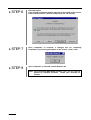
WINCAPSII GUIDE
(Ver. 1.95)
Copyright © DENSO WAVE INCORPORATED, 2002
All rights reserved. No part of this publication may be reproduced in any form or by any means without
permission in writing from the publisher.
Specifications are subject to change without prior notice.
All products and company names mentioned are trademarks or registered trademarks of their
respective holders
Preface
Thank you for purchasing the WINCAPSII. It is designed for efficient program development and
verification of the DENSO robot on your PC connected to the robot controller (NetwoRC).
WINCAPSII also makes it possible to verify robot programs and data at a remote location via
telephone line.
On your PC, WINCAPSII allows you to simulate robot motions, variables, I/Os or manage
program files in units of project, helping you easily develop and manage programs.
Before using WINCAPSII, read this manual carefully to safely get the maximum benefit from
your WINCAPSII system.
Version compatibility between WINCAPSII and robot controller software (OS)
WINCAPSII is compatible with the same or earlier versions of the robot controller OS.
WINCAPSII version 1.0 is compatible with robot controller OS version 1.0.
WINCAPSII version 1.1 is compatible with robot controller OS versions 1.0 and 1.1.
WINCAPSII version 1.2 is compatible with robot controller OS versions 1.0, 1.1, and 1.2
If your Robot Controller is newer than WINCAPS II in software version, upgrade the
WINCAPS II version using the DENSO Robot NetwoRC CD packaged together with the
Robot Controller.
WINCAPSII version is printed on the label of the WINCAPSII floppy disk or compact
disk. For the checking procedure of robot controller OS version, refer to the OWNER'S
MANUAL of your robot.
i
Contents of WINCAPS II
Important
To ensure operator safety, be sure to read the precautions and instructions in "SAFETY
PRECAUTIONS" pages 1 through 9.
NOTICE TO USER
DENSO WAVE INCORPORATED grants you a non-exclusive, non-transferable license to use
WINCAPSII ("Software").
1. COPYRIGHT
(1) The Software is protected by copyright laws and international copyright treaties, as well as
other intellectual property laws and treaties.
(2) All title and copyrights in and to the Software, the accompanying printed materials, and any
copies of the Software are owned by DENSO WAVE INCORPORATED.
2. GRANT OF LICENSE
(1) You may use one copy of the Software on a single computer at one time.
(2) You may either make one copy of the Software solely for backup or archival purposes, or
install the Software on a single computer provided you keep the original solely for backup or
archival purposes.
3. DESCRIPTION OF OTHER RIGHTS AND LIMITATIONS
(1) You shall not rent, lease, sell, sublicense, assign, or otherwise transfer the Software.
(2) You shall not reverse engineer, decompile, disassemble, merge, modify or translate the
Software.
4. LIMITED WARRANTY
(1) If the Software disk is defective or the accompanying documentation is defective (e.g.,
omissions), the entire and exclusive liability and remedy shall be limited to either the repair or
replacement of the Software. This warranty is limited to two month period following your
receipt of the Software.
(2) In no event shall DENSO WAVE INCORPORATED be liable for any consequential,
incidental or special damages, including any lost profits or lost savings, even if a DENSO
WAVE INCORPORATED representative has been advised of the possibility of such
damages, or for any claim by any third party.
ii
Contents of WINCAPS II
The WINCAPS II package consists of the following.
Software
< CD-ROM version>
Instruction Manuals
WINCAPS II GUIDE
(this book)
<Floppy disk version>
Note: The
CD-ROM
version contains this
book in the PDF file
format.
5. Required operating environments
The following operating environments are required for running WINCAPSII smoothly.
Table 3-5 Operating Environments for the PC Teaching System Software
CPU
Pentium or higher capacity
OS
Windows 95 or upper version (See Note 1.)
Memory
32 MB or more (64 MB recommended)
Hard disk
A free area of 80 MB or more is required at installation.
Monitor resolution
640 × 480 or higher
Note 1
WINCAPS cannot run properly on earlier versions of Windows 95.
The version of Windows 95 can be checked with [Control Panel –
System – Information]. If A, B or C is not displayed (no symbol) at
the end of the version information (4.00, 95B), update your
Windows 95 with the Windows 95 Service Pack 1 that is available
from the Microsoft's web site.
iii
Before Using WINCAPS II
Before Using WINCAPS II
1. Release restrictions on WINCAPS II functions
Without entry of User ID, WINCAPS II does not operate except “PRO1”, which is designed to
operate for the trial purpose. On activation of WINCAPS II, the license information screen appears.
Enter User ID printed in the license card.
2. Store the license card with care
The User ID printed in the license card is your purchased product number. The User ID is needed
when you receive after-sales service. Keep the license card with care.
iv
How the documentation set is organized
How the documentation set is organized
The documentation set consists of the following six books. If you are unfamiliar with this robot series,
please read all four books and understand them fully before operating your robot.
BEGINNER’S GUIDE
Explains the outline of DENSO robot, operation with the teach pendant, and programming
with WINCAPS II by giving practical examples. Use this guidebook when you want to know
the fundamental usage of the robot.
INSTALLATION & MAINTENANCE GUIDE
Explains the outline of robot, installation of the robot components, and their maintenance and
inspection procedures.
SETTING-UP MANUAL - operation of the teach pendant, mini-pendant and operating panel Explains the basic operations and auxiliary functions of your robot, and operation of optional
equipment.
WINCAPS II GUIDE - this book Explains how to use the personal computer teaching system, which allows you to develop and
manage the robot operation programs from your PC connected to the robot and the robot
controller.
PROGRAMMER’S MANUAL
Explains the programming language (PAC), programming method with PAC, and command
specifications.
ERROR CODE TABLES
Lists the error codes displayed on the teach pendant, mini-pendant, operating panel, or
personal computer screen when an error occurs in the robot or WINCAPS II. This book also
provides explanation of and remedy for individual errors.
v
How this book is organized
How this book is organized
This book is just one part of the documentation set. It consists of SAFETY PRECAUTIONS, ten
chapters, appendices, and index
SAFETY PRECAUTIONS
Defines safety terms and related symbols and provides precautions to be observed. Be sure to read
this section before operating your robot.
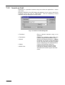
Chapter 1 Outline of Personal Computer Teaching System
Describes the configuration of the personal computer teaching system and its features.
Chapter 2 Setting Personal Computer Teaching System
Describes how to make connections and setting of the personal computer teaching system.
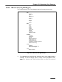
Chapter 3 Starting Teaching System and Knowing Each Manager
Describes the procedures for starting and terminating the personal computer teaching system and
outlines the functions of each Manager.
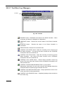
Chapter 4 System Manager
Describes the functions and operation of the system manager that constitutes the nucleus of
WINCAPSII software to be used for the personal computer teaching system.
Chapter 5 Operating PAC Program Manager
Describes PAC Program Manager of WINCAPSII software functions.
Chapter 6 Operating Variable Manager
Describes Variable Manager of WINCAPSII software functions.
Chapter 7 Operating DIO Manager
Describes DIO Manager of WINCAPSII software functions.
Chapter 8 Operating Arm Manager
Describes Arm Manager of WINCAPSII software functions.
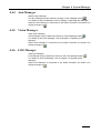
Chapter 9 Operating Vision Manager
Describes Vision Manager of WINCAPSII software functions.
vi
How this book is organized
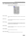
Chapter 10 Operating Log Manager
Describes Log Manager of WINCAPSII software functions.
Index
vii
SAFETY PRECAUTIONS
SAFETY PRECAUTIONS
Be sure to observe all of the following safety precautions.
Strict observance of these warning and caution indications are a MUST for preventing accidents, which
could result in bodily injury and substantial property damage. Make sure you fully understand all
definitions of these terms and related symbols given below, before you proceed to the text itself.
WARNING
Alerts you to those conditions, which could result
in serious bodily injury or death if the instructions
are not followed correctly.
CAUTION
Alerts you to those conditions, which could result
in minor bodily injury or substantial property
damage if the instructions are not followed
correctly.
Terminology and Definitions
Maximum space: Refers to the volume of space encompassing the maximum designed movements of
all robot parts including the end-effector, workpiece and attachments. (Quoted from the RIA*
Committee Draft.)
Restricted space: Refers to the portion of the maximum space to which a robot is restricted by limiting
devices (i.e., mechanical stops). The maximum distance that the robot, end-effector, and workpiece
can travel after the limiting device is actuated defines the boundaries of the restricted space of the
robot. (Quoted from the RIA Committee Draft.)
Motion space: Refers to the portion of the restricted space to which a robot is restricted by software
motion limits. The maximum distance that the robot, end-effector, and workpiece can travel after the
software motion limits are set defines the boundaries of the motion space of the robot. (The "motion
space" is Denso-proprietary terminology.)
Operating space: Refers to the portion of the restricted space (or motion space in Denso) that is
actually used by the robot while performing its task program. (Quoted from the RIA Committee Draft.)
Task program: Refers to a set of instructions for motion and auxiliary functions that define the specific
intended task of the robot system. (Quoted from the RIA Committee Draft.)
(*RIA: Robotic Industries Association)
1
1. Introduction
This section provides safety precautions to be observed during
installation, teaching, inspection, adjustment, and maintenance
of the robot.
2. Installation Precautions
2.1 Insuring the proper
installation environment
2.1.1 For standard type
The standard type has not been designed to withstand
explosions, dust-proof, nor is it splash-proof. Therefore, it
should not be installed in any environment where:
(1) there are flammable gases or liquids,
(2) there are any shavings from metal processing or other
conductive material flying about,
(3) there are any acidic, alkaline or other corrosive gases,
(4) there is cutting or grinding oil mist,
(5) it may likely be submerged in fluid,
(6) there is sulfuric cutting or grinding oil mist, or
(7) there are any large-sized inverters, high output/high
frequency transmitters, large contactors, welders, or other
sources of electrical noise.
2.1.2 For dust-proof, splashproof type
The dust-proof, splash-proof type is an IP54-equivalent dustproof and splash-proof structure, but it has not been designed
to withstand explosions. (The wrist of the VM-D-W or VS-E-W
is an IP65-equivalent dust-proof and splash-proof structure.)
Note that the robot controller is not a dust- or splash-proof
structure. Therefore, when using the robot controller in an
environment exposed to mist, put it in an optional protective
box.
The dust-proof, splash-proof type should not be installed in any
environment where:
(1) there are any flammable gases or liquids,
(2) there are any acidic, alkaline or other corrosive gases,
(3) there are any large-sized inverters, high output/high
frequency transmitters, large contactors, welders, or other
sources of electrical noise,
(4) it may likely be submerged in fluid,
(5) there are any grinding or machining chips or shavings,
(6) any machining oil other than DENSO authorized oil is in
use, or
Note: DENSO authorized oil: Yushiron Oil No. 4C (nonsoluble)
(7) there is sulfuric cutting or grinding oil mist.
2.2 Service space
2
The robot and peripheral equipment should be installed so that
sufficient service space is maintained for safe teaching,
maintenance, and inspection.
SAFETY PRECAUTIONS
2.3 Control devices
outside the robot's
restricted space
The robot controller, teach pendant, and operating panel should
be installed outside the robot's restricted space and in a place
where you can observe all of the robot’s movements when
operating the robot controller, teach pendant, or operating
panel.
2.4 Positioning of gauges
Pressure gauges, oil pressure gauges and other gauges should
be installed in an easy-to-check location.
2.5 Protection of electrical
wiring and
hydraulic/pneumatic
piping
If there is any possibility of the electrical wiring or
hydraulic/pneumatic piping being damaged, protect them with a
cover or similar item.
2.6 Positioning of
emergency stop
switches
Emergency stop switches should be provided in a position
where they can be reached easily should it be necessary to
stop the robot immediately.
(1) The emergency stop switches should be red.
(2) Emergency stop switches should be designed so that they
will not be released after pressed, automatically or
mistakenly by any other person.
(3) Emergency stop switches should be separate from the
power switch.
2.7 Positioning of
operating status
indicators
Operating status indicators should be positioned in such a way
where workers can easily see whether the robot is on
temporary halt or on an emergency or abnormal stop.
3
2.8 Setting-up the safety
fence or enclosure
A safety fence or enclosure should be set up so that no one can
easily enter the robot's restricted space. If it is impossible,
utilize other protectors as described in Section 2.9.
(1) The fence or enclosure should be constructed so that it
cannot be easily moved or removed.
(2) The fence or enclosure should be constructed so that it
cannot be easily damaged or deformed through external
force.
(3) Establish the exit/entrance to the fence or enclosure.
Construct the fence or enclosure so that no one can easily
get past it by climbing over the fence or enclosure.
(4) The fence or enclosure should be constructed to ensure
that it is not possible for hands or any other parts of the
body to get through it.
(5) Take any one of the following protections for the entrance/
exit of the fence or enclosure:
1) Place a door, rope or chain across the entrance/exit of
the fence or enclosure, and fit it with an interlock that
ensures the emergency stop device operates
automatically if it is opened or removed.
2) Post a warning notice at the entrance/exit of the fence
or enclosure stating "In operation--Entry forbidden" or
"Work in progress--Do not operate" and ensure that
workers follow these instructions at all times.
When making a test run, before setting up the fence or
enclosure, place an overseer in a position outside the
robot’s restricted space and one in which he/she can
see all of the robot’s movements. The overseer should
prevent workers from entering the robot's restricted
space and be devoted solely to that task.
2.9 Positioning of rope or
chain
If it is not possible to set up the safety fence or enclosure
described in Section 2.8, hang a rope or chain around the
perimeter of the robot’s restricted space to ensure that no one
can enter the restricted space.
(1) Ensure the support posts cannot be moved easily.
(2) Ensure that the rope or chain’s color or material can easily
be discerned from the surrounds.
(3) Post a warning notice in a position where it is easy to see
stating "In operation--Entry forbidden" or "Work in progress
--Do not operate" and ensure that workers follow these
instructions at all times.
(4) Set the exit/entrance, and follow the instructions given in
Section 2.8, (3) through (5).
4
SAFETY PRECAUTIONS
2.10 Setting the robot's
motion space
The area required for the robot to work is called the robot's
operating space.
If the robot’s motion space is greater than the operating space,
it is recommended that you set a smaller motion space to
prevent the robot from interfering or disrupting other equipment.
Refer to the "INSTALLATION & MAINTENANCE GUIDE"
Chapter 4.
2.11 No robot modification
allowed
Never modify the robot unit, robot controller, teach pendant or
other devices.
2.12 Cleaning of tools
If your robot uses welding guns, paint spray nozzles, or other
end-effectors requiring cleaning, it is recommended that the
cleaning process be carried out automatically.
2.13 Lighting
Sufficient illumination should be assured for safe robot
operation.
2.14 Protection from objects
thrown by the endeffector
If there is any risk of workers being injured in the event that the
object being held by the end-effector is dropped or thrown by
the end-effector, consider the size, weight, temperature and
chemical nature of the object and take appropriate safeguards
to ensure safety.
2.15 Affixing the warning
label
Place the warning label packaged
with the robot on the exit/entrance
of the safety fence or in a position
where it is easy to see.
5
3. Precautions
while robot is
running
Warning
Touching the robot while it is
in operation can lead to
serious injury. Please ensure
the following conditions are
maintained and that the
cautions listed from Section
3.1 onwards are followed
when any work is being
performed.
1) Do not enter the robot's restricted space when the robot
is in operation or when the motor power is on.
2) As a precaution against malfunction, ensure that an
emergency stop device is activated to cut the power to
the robot motor upon entry into the robot's restricted
space.
3) When it is necessary to enter the robot's restricted
space to perform teaching or maintenance work while
the robot is running, ensure that the steps described in
Section 3.3 "Ensuring safety of workers performing jobs
within the robot's restricted space" are taken.
3.1 Creation of working
regulations and
assuring worker
adherence
When entering the robot’s restricted space to perform teaching
or maintenance inspections, set "working regulations" for the
following items and ensure workers adhere to them.
(1) Operating procedures required to run the robot.
(2) Robot speed when performing teaching.
(3) Signaling methods to be used when more than one worker
is to perform work.
(4) Steps that must be taken by the worker in the event of a
malfunction, according to the contents of the malfunction.
(5) The necessary steps for checking release and safety of the
malfunction status, in order to restart the robot after robot
movement has been stopped due to activation of the
emergency stop device
(6) Apart from the above, any steps below necessary to
prevent danger from unexpected robot movement or
malfunction of the robot.
1) Display of the control panel (See Section 3.2 on the
following page)
2) Assuring the safety of workers performing jobs within
the robot's restricted space (See Section 3.3 on the
following page)
3) Maintaining worker position and stance
Position and stance that enables the worker to confirm
normal robot operation and to take immediate refuge if
a malfunction occurs.
6
SAFETY PRECAUTIONS
4) Implementation of measures for noise prevention
5) Signaling methods for workers of related equipment
6) Types of malfunctions and how to distinguish them
Please ensure "working regulations" are appropriate to the
robot type, the place of installation and to the content of the
work.
Be sure to consult the opinions of related workers, engineers at
the equipment manufacturer and that of a labor safety
consultant when creating these "working regulations".
3.2 Display of operation
panel
To prevent anyone other than the worker from accessing the
start switch or the changeover switch by accident during
operation, display something to indicate it is in operation on the
operating panel or teach pendant. Take any other steps as
appropriate, such as locking the cover.
3.3 Ensuring safety of
workers performing
jobs within the robot's
restricted space
When performing jobs within the robot’s restricted space, take
any of the following steps to ensure that robot operation can be
stopped immediately upon a malfunction.
(1) Ensure an overseer is placed in a position outside the
robot’s restricted space and one in which he/she can see
all robot movements, and that he/she is devoted solely to
that task.
Q An emergency stop device should be activated
immediately upon a malfunction.
R Do not permit anyone other than the worker engaged
for that job to enter the robot’s restricted space.
(2) Ensure a worker within the robot's restricted space carries
the portable emergency stop switch so he/she can press it
(the robot stop button on the teach pendant) immediately if
it should be necessary to do so.
7
3.4 Inspections before
commencing work
such as teaching
Before starting work such as teaching, inspect the following
items, carry out any repairs immediately upon detection of a
malfunction and perform any other necessary measures.
(1) Check for any damage to the sheath or cover of the
external wiring or to the external devices.
(2) Check that the robot is functioning normally or not (any
unusual noise or vibration during operation).
(3) Check the functioning of the emergency stop device.
(4) Check there is no leakage of air or oil from any pipes.
(5) Check there are no obstructive objects in or near the
robot’s restricted space.
3.5 Release of residual air
pressure
Before disassembling or replacing pneumatic parts, first release
any residual air pressure in the drive cylinder.
3.6 Precautions for test
runs
Whenever possible, have the worker stay outside of the robot's
restricted space when performing test runs.
3.7 Precautions for
automatic operation
(1) At start-up
Before the robot is to be started up, first check the following
items as well as setting the signals to be used and perform
signaling practice with all related workers.
1) Check that there is no one inside the robot’s restricted
space.
2) Check that the teach pendant and tools are in their
designated places.
3) Check that no lamps indicating a malfunction on the
robot or related equipment are lit.
(2) Check that the display lamp indicating automatic operation
is lit during automatic operation.
(3) Steps to be taken when a malfunction occurs
Should a malfunction occur with the robot or related
equipment and it is necessary to enter the robot's restricted
space to perform emergency maintenance, stop the robot’s
operation by activating the emergency stop device. Take
any necessary steps such as placing a display on the
starter switch to indicate work is in progress to prevent
anyone from accessing the robot.
8
SAFETY PRECAUTIONS
3.8 Precautions in repairs
(1) Do not perform repairs outside of the designated range.
(2) Under no circumstances should the interlock mechanism
be removed.
(3) When opening the robot controller's cover for battery
replacement or any other reasons, always turn the robot
controller power off and disconnect the power cable.
(4) Use only spare tools authorized by DENSO.
4. Daily and periodical
inspections
(1) Be sure to perform daily and periodical inspections. Before
starting jobs, always check that there is no problem with the
robot and related equipment. If any problems are found,
take any necessary measures to correct them.
(2) When carrying out periodical inspections or any repairs,
maintain records and keep them for at least 3 years.
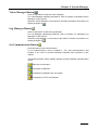
5. Management of
floppy disks
(1) Carefully handle and store the "Initial settings" floppy disks
packaged with the robot, which store special data
exclusively prepared for your robot.
(2) After finishing teaching or making any changes, always
save the programs and data onto floppy disks.
Making back-ups will help you recover if data stored in the
robot controller is lost due to the expired life of the back-up
battery.
(3) Write the names of each of the floppy disks used for storing
task programs to prevent incorrect disks from loading into
the robot controller.
(4) Store the floppy disks where they will not be exposed to
dust, humidity and magnetic field, which could corrupt the
disks or data stored on them.
9
10
CONTENTS
Preface.................................................................................................................................................................................i
Before Using WINCAPS II..............................................................................................................................................iv
How the documentation set is organized.........................................................................................................................v
How this book is organized..............................................................................................................................................vi
SAFETY PRECAUTIONS ...............................................................................................................................................1
Chapter1 Outline of Personal Computer Teaching System
1.1
Features of Personal Computer Teaching System .......................................................................................... 1-1
1.2
System Configuration..................................................................................................................................... 1-1
1.2.1 RS232C Connection................................................................................................................................... 1-2
1.2.2 Ethernet Connection................................................................................................................................... 1-4
1.2.3 Modem Connection .................................................................................................................................... 1-6
1.3
Security........................................................................................................................................................... 1-8
1.3.1 User Level .................................................................................................................................................. 1-8
1.3.2 Password .................................................................................................................................................... 1-9
Chapter2 Setting Personal Computer Teaching System
2.1
Installing WINCAPSII Software .................................................................................................................... 2-1
2.1.1 Installation Procedures ............................................................................................................................... 2-2
2.1.2 Uninstall ..................................................................................................................................................... 2-6
2.2
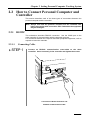
How to Connect Personal Computer and Controller ...................................................................................... 2-9
2.2.1 RS232C ...................................................................................................................................................... 2-9
2.2.2 Telephone Line......................................................................................................................................... 2-20
2.2.3 Ethernet .................................................................................................................................................... 2-25
Chapter3 Starting Teaching System and Knowing Each Manager
3.1
Starting Personal Computer Teaching System................................................................................................ 3-1
3.2
Terminating Personal Computer Teaching System......................................................................................... 3-4
3.2.1 Terminating Personal Computer................................................................................................................. 3-4
3.2.2 Terminating Robot Controller Connected with Personal Computer........................................................... 3-4
3.3
Function Outline of Each Manager ................................................................................................................ 3-5
Chapter4 System Manager
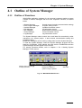
4.1
Outline of System Manager............................................................................................................................ 4-1
4.1.1 Outline of Functions................................................................................................................................... 4-1
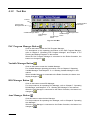
4.1.2 Tool Bar...................................................................................................................................................... 4-2
4.1.3 System Project Management ...................................................................................................................... 4-4
4.1.4 Menu List ................................................................................................................................................... 4-8
4.2
File Menu ....................................................................................................................................................... 4-9
4.2.1 New Project................................................................................................................................................ 4-9
4.2.2 Open Project..............................................................................................................................................4-11
4.2.3 Save Project...............................................................................................................................................4-11
4.2.4 Save Project As .........................................................................................................................................4-11
4.2.5 Transfer Project ........................................................................................................................................ 4-12
4.2.6 Project Information .................................................................................................................................. 4-12
4.2.7 Exit ........................................................................................................................................................... 4-12
4.3
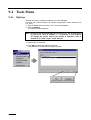
Tools Menu................................................................................................................................................... 4-13
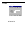
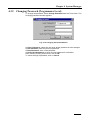
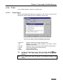
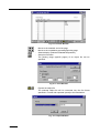
4.3.1 Set Communication .................................................................................................................................. 4-13
4.3.2 Changing Password (Programmer Level)................................................................................................. 4-21
4.3.3 Re-Log In ................................................................................................................................................. 4-22
4.3.4 Reading FD Images.................................................................................................................................. 4-23
4.3.5 Write FD Images ...................................................................................................................................... 4-26
4.4
Window Menu .............................................................................................................................................. 4-30
4.4.1 PAC Manager ........................................................................................................................................... 4-30
4.4.2 Variable Manager ..................................................................................................................................... 4-30
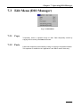
4.4.3 DIO Manager ........................................................................................................................................... 4-30
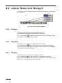
4.4.4 Arm Manager ........................................................................................................................................... 4-31
4.4.5 Vision Manager ........................................................................................................................................ 4-31
4.4.6 LOG Manager .......................................................................................................................................... 4-31
4.5
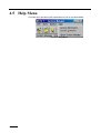
Help Menu.................................................................................................................................................... 4-32
4.5.1 License Key.............................................................................................................................................. 4-33
4.5.2 System Extension ..................................................................................................................................... 4-34
4.5.3 About System Manager ............................................................................................................................ 4-34
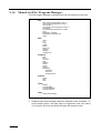
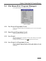
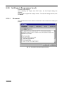
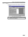
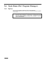
Chapter5 Operating PAC Program Manager
5.1
Outline of PAC Program Manager ................................................................................................................. 5-1
5.1.1 Outline of Functions................................................................................................................................... 5-1
5.1.2 Tool Bar...................................................................................................................................................... 5-1
5.1.3 Basic Usage................................................................................................................................................ 5-3
5.1.4 File Management........................................................................................................................................ 5-5
5.1.5 Menu List (PAC Program Manager) .......................................................................................................... 5-8
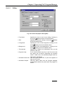
5.2
File Menu (PAC Program Manager)............................................................................................................... 5-9
5.2.1 New Project (Programmer Level) .............................................................................................................. 5-9
5.2.2 Open Project (Programmer Level) ............................................................................................................. 5-9
5.2.3 Save Project................................................................................................................................................ 5-9
5.2.4 Save Project As (Programmer Level) ......................................................................................................... 5-9
5.2.5 Set Project (Programmer Level)............................................................................................................... 5-10
5.2.6 Transmit Project ....................................................................................................................................... 5-15
5.2.7 Print.......................................................................................................................................................... 5-16
5.2.8 Make Exec. Program ................................................................................................................................ 5-19
5.2.9 Make Macro Definition File..................................................................................................................... 5-19
5.2.10 Close......................................................................................................................................................... 5-19
5.3
Edit Menu (PAC Program Manager) ............................................................................................................ 5-20
5.3.1 Undo......................................................................................................................................................... 5-20
5.3.2 Cut............................................................................................................................................................ 5-20
5.3.3 Copy ......................................................................................................................................................... 5-20
5.3.4 Paste ......................................................................................................................................................... 5-20
5.3.5 Delete ....................................................................................................................................................... 5-20
5.3.6 Select All .................................................................................................................................................. 5-20
5.3.7 Search....................................................................................................................................................... 5-21
5.3.8 Replace..................................................................................................................................................... 5-22
5.3.9 Jump To .................................................................................................................................................... 5-23
5.4
Program Menu.............................................................................................................................................. 5-24
5.4.1 New .......................................................................................................................................................... 5-24
5.4.2 Save.......................................................................................................................................................... 5-24
5.4.3 Save As..................................................................................................................................................... 5-25
5.4.4 Add........................................................................................................................................................... 5-26
5.4.5 Release ..................................................................................................................................................... 5-26
5.4.6 Syntax Check ........................................................................................................................................... 5-26
5.4.7 Import....................................................................................................................................................... 5-27
5.4.8 Export....................................................................................................................................................... 5-27
5.4.9 Rearrange ................................................................................................................................................. 5-27
5.5
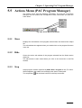
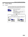
Actions Menu (PAC Program Manager) ...................................................................................................... 5-29
5.5.1 Show......................................................................................................................................................... 5-29
5.5.2 Hide.......................................................................................................................................................... 5-29
5.5.3 Stop .......................................................................................................................................................... 5-29
5.6
Tools Menu (PAC Program Manager) .......................................................................................................... 5-30
5.6.1 Options ..................................................................................................................................................... 5-30
5.6.2 Program Bank........................................................................................................................................... 5-36
5.6.3 Command Builder .................................................................................................................................... 5-43
5.6.4 Program Monitor ...................................................................................................................................... 5-45
5.7
Help Menu.................................................................................................................................................... 5-49
5.7.1 About PAC Manager ................................................................................................................................ 5-49
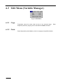
Chapter6 Operating Variable Manager
6.1
Outline of Variable Manager .......................................................................................................................... 6-1
6.1.1 Outline of Functions................................................................................................................................... 6-1
6.1.2 Tool Bar...................................................................................................................................................... 6-2
6.1.3 Basic Usage................................................................................................................................................ 6-3
6.1.4 Files to Be Managed..................................................................................................................................6-11
6.1.5 Menu List ................................................................................................................................................. 6-12
6.2
File Menu (Variable Manager) ..................................................................................................................... 6-13
6.2.1 New (Programmer Level)......................................................................................................................... 6-13
6.2.2 Open (Programmer Level)........................................................................................................................ 6-13
6.2.3 Save.......................................................................................................................................................... 6-13
6.2.4 Save As (Programmer Level) ................................................................................................................... 6-14
6.2.5 Transfer .................................................................................................................................................... 6-14
6.2.6 Print.......................................................................................................................................................... 6-15
6.2.7 Make Macro Define File .......................................................................................................................... 6-17
6.2.8 Import Macro Define File......................................................................................................................... 6-17
6.2.9 Close......................................................................................................................................................... 6-17
6.3
Edit Menu (Variable Manager) ..................................................................................................................... 6-18
6.3.1 Copy ......................................................................................................................................................... 6-18
6.3.2 Paste ......................................................................................................................................................... 6-18
6.3.3 Search on Grid.......................................................................................................................................... 6-19
6.4
Actions Menu (Variable Manager) ............................................................................................................... 6-20
6.4.1 Connect .................................................................................................................................................... 6-20
6.4.2 Snapshot ................................................................................................................................................... 6-20
6.4.3 Monitor..................................................................................................................................................... 6-20
6.4.4 Get Pose ................................................................................................................................................... 6-21
6.4.5 Move ........................................................................................................................................................ 6-21
6.5
Tools Menu (Variable Manager)................................................................................................................... 6-22
6.5.1 Options ..................................................................................................................................................... 6-22
6.6
Help Menu.................................................................................................................................................... 6-26
6.6.1 About Variable Manager .......................................................................................................................... 6-26
Chapter7 Operating DIO Manager
7.1
Outline of DIO Manager ................................................................................................................................ 7-1
7.1.1 Outline of Functions................................................................................................................................... 7-1
7.1.2 Tool Bar...................................................................................................................................................... 7-2
7.1.3 Table Item................................................................................................................................................... 7-3
7.1.4 Basic Usage................................................................................................................................................ 7-4
7.1.5 Files to Be Managed................................................................................................................................... 7-6
7.1.6 Menu List (DIO Manager) ......................................................................................................................... 7-7
7.2
File Menu (DIO Manager).............................................................................................................................. 7-8
7.2.1 New (Programmer Level)........................................................................................................................... 7-8
7.2.2 Open (Programmer Level).......................................................................................................................... 7-8
7.2.3 Save............................................................................................................................................................ 7-8
7.2.4 Save As (Programmer Level) ..................................................................................................................... 7-9
7.2.5 Transfer ...................................................................................................................................................... 7-9
7.2.6 Print.......................................................................................................................................................... 7-10
7.2.7 Make Macro Define File .......................................................................................................................... 7-12
7.2.8 Import Macro Define File......................................................................................................................... 7-12
7.2.9 Close......................................................................................................................................................... 7-12
7.3
Edit Menu (DIO Manager) ........................................................................................................................... 7-13
7.3.1 Copy ......................................................................................................................................................... 7-13
7.3.2 Paste ......................................................................................................................................................... 7-13
7.3.3 Search on Grid.......................................................................................................................................... 7-14
7.3.4 Selected Range All ON ............................................................................................................................ 7-15
7.3.5 Selected Range All OFF ........................................................................................................................... 7-15
7.4
Actions Menu (DIO Manager) ..................................................................................................................... 7-16
7.4.1 Connect .................................................................................................................................................... 7-16
7.4.2 Snapshot ................................................................................................................................................... 7-16
7.4.3 Monitor..................................................................................................................................................... 7-17
7.4.4 Pseudo input/output.................................................................................................................................. 7-17
7.4.5 Display Format......................................................................................................................................... 7-17
7.5
Tools Menu (DIO Manager) ......................................................................................................................... 7-23
7.5.1 Options ..................................................................................................................................................... 7-23
7.5.2 DIO Command Viewer............................................................................................................................. 7-27
7.6
Help Menu.................................................................................................................................................... 7-28
7.6.1 About DIO Manager................................................................................................................................. 7-28
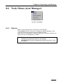
Chapter8 Operating Arm Manager
8.1
Outline of Arm Manager ................................................................................................................................ 8-1
8.1.1 Outline of Functions................................................................................................................................... 8-1
8.1.2 Tool Bar (Arm Manager)............................................................................................................................ 8-2
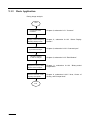
8.1.3 Basic Application ....................................................................................................................................... 8-4
8.1.4 Files to Manage .......................................................................................................................................... 8-6
8.1.5 Menu List (Arm Manager) ......................................................................................................................... 8-7
8.2
File Menu (Arm Manager) ............................................................................................................................. 8-8
8.2.1 New (Programmer level) ............................................................................................................................ 8-8
8.2.2 Open (Programmer level)........................................................................................................................... 8-8
8.2.3 Save............................................................................................................................................................ 8-8
8.2.4 Save As (Programmer level)....................................................................................................................... 8-9
8.2.5 Transfer ...................................................................................................................................................... 8-9
8.2.6 Print.......................................................................................................................................................... 8-10
8.2.7 Close......................................................................................................................................................... 8-12
8.3
Edit Menu (Arm Manager) ........................................................................................................................... 8-13
8.3.1 Cut............................................................................................................................................................ 8-13
8.3.2 Copy ......................................................................................................................................................... 8-13
8.3.3 Paste ......................................................................................................................................................... 8-13
8.3.4 Rename..................................................................................................................................................... 8-13
8.3.5 Reconfigure .............................................................................................................................................. 8-13
8.4
Actions Menu (Arm Manager) ..................................................................................................................... 8-14
8.4.1 Connect .................................................................................................................................................... 8-14
8.4.2 Snapshot ................................................................................................................................................... 8-14
8.4.3 Monitor..................................................................................................................................................... 8-14
8.5
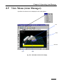
View Menu (Arm Manager) ......................................................................................................................... 8-15
8.5.1 Arm .......................................................................................................................................................... 8-16
8.5.2 Tool .......................................................................................................................................................... 8-16
8.5.3 Work......................................................................................................................................................... 8-16
8.5.4 Area.......................................................................................................................................................... 8-16
8.5.5 Obstacle.................................................................................................................................................... 8-16
8.6
Tools Menu (Arm Manager)......................................................................................................................... 8-17
8.6.1 Options ..................................................................................................................................................... 8-17
8.6.2 Remote Operation .................................................................................................................................... 8-23
8.6.3 Object Trees ............................................................................................................................................. 8-24
8.6.4 Pose Data Conversion .............................................................................................................................. 8-27
8.7
Help Menu.................................................................................................................................................... 8-28
8.7.1 About Arm Manager................................................................................................................................. 8-28
Chapter9 Operating Vision Manager
9.1
Outline of Vision Manager ............................................................................................................................. 9-1
9.1.1 Outline of Functions................................................................................................................................... 9-1
9.1.2 Tool Bar...................................................................................................................................................... 9-5
9.1.3 Basic Application ....................................................................................................................................... 9-6
9.1.4 Files to Be Managed................................................................................................................................... 9-7
9.1.5 Menu List ................................................................................................................................................... 9-9
9.2
File Menu ..................................................................................................................................................... 9-10
9.2.1 New (Programmer level) .......................................................................................................................... 9-10
9.2.2 Open (Programmer level)......................................................................................................................... 9-10
9.2.3 Save.......................................................................................................................................................... 9-10
9.2.4 Save As (Programmer level)..................................................................................................................... 9-10
9.2.5 Transfer .....................................................................................................................................................9-11
9.2.6 Save Image Data As ................................................................................................................................. 9-13
9.2.7 Open Image Data...................................................................................................................................... 9-13
9.2.8 Print.......................................................................................................................................................... 9-14
9.2.9 Make Macro Definition File..................................................................................................................... 9-16
9.2.10 Import Macro Definition File ................................................................................................................... 9-16
9.2.11 Close......................................................................................................................................................... 9-16
9.3
Actions Menu ............................................................................................................................................... 9-17
9.3.1 Connect .................................................................................................................................................... 9-17
9.3.2 Get Info .................................................................................................................................................... 9-19
9.4
Tools Menu................................................................................................................................................... 9-20
9.4.1 Options ..................................................................................................................................................... 9-20
9.4.2 Edit Macro Name ..................................................................................................................................... 9-25
9.4.3 Edit Window............................................................................................................................................. 9-26
9.4.4 Edit Search Model.................................................................................................................................... 9-33
9.4.5 Calibration................................................................................................................................................ 9-38
9.4.6 Image Analysis ......................................................................................................................................... 9-45
9.5
Visually Calibrating Robot Position ............................................................................................................. 9-67
9.5.1 Work Flow................................................................................................................................................ 9-67
9.5.2 Calibration of Robot Coordinates and Vision Coordinates ...................................................................... 9-68
9.5.3 Camera Calibration Procedure ................................................................................................................. 9-69
9.5.4 Program Example..................................................................................................................................... 9-70
9.5.5 Executing Program................................................................................................................................... 9-71
9.6
Help Menu.................................................................................................................................................... 9-72
9.6.1 About Vision Manager ............................................................................................................................. 9-72
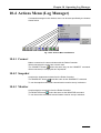
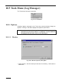
Chapter10 Operating Log Manager
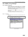
10.1 Outline of Log Manager ............................................................................................................................... 10-1
10.1.1 Outline of Functions................................................................................................................................. 10-1
10.1.2 Tool Bar (Log Manager)........................................................................................................................... 10-6
10.1.3 Basic Usage.............................................................................................................................................. 10-7
10.1.4 Files to Be Managed................................................................................................................................. 10-8
10.1.5 Menu List (Log Manager) ........................................................................................................................ 10-9
10.2 File Menu (Log Manager) .......................................................................................................................... 10-10
10.2.1 New (Programmer Level)....................................................................................................................... 10-10
10.2.2 Open (Programmer Level)...................................................................................................................... 10-10
10.2.3 Save........................................................................................................................................................ 10-10
10.2.4 Save As (Programmer Level) ..................................................................................................................10-11
10.2.5 Receive....................................................................................................................................................10-11
10.2.6 Print........................................................................................................................................................ 10-12
10.2.7 Import..................................................................................................................................................... 10-14
10.2.8 Export..................................................................................................................................................... 10-14
10.2.9 Close....................................................................................................................................................... 10-14
10.3 Edit Menu (Log Manager).......................................................................................................................... 10-15
10.3.1 Undo....................................................................................................................................................... 10-15
10.3.2 Cut.......................................................................................................................................................... 10-15
10.3.3 Copy ....................................................................................................................................................... 10-15
10.3.4 Paste ....................................................................................................................................................... 10-15
10.3.5 Delete ..................................................................................................................................................... 10-15
10.3.6 Select All ................................................................................................................................................ 10-15
10.3.7 Search..................................................................................................................................................... 10-16
10.3.8 Replace................................................................................................................................................... 10-17
10.3.9 Search on Grid........................................................................................................................................ 10-18
10.4 Actions Menu (Log Manager) .................................................................................................................... 10-19
10.4.1 Connect .................................................................................................................................................. 10-19
10.4.2 Snapshot ................................................................................................................................................. 10-19
10.4.3 Monitor................................................................................................................................................... 10-19
10.4.4 Begin Control Log.................................................................................................................................. 10-20
10.4.5 End Control Log..................................................................................................................................... 10-20
10.4.6 Clear Control Log................................................................................................................................... 10-20
10.4.7 Reproduce Control Log Action .............................................................................................................. 10-20
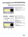
10.4.8 Graph Control Log ................................................................................................................................. 10-21
10.5 Tools Menu (Log Manager)........................................................................................................................ 10-22
10.5.1 Options ................................................................................................................................................... 10-22
10.5.2 Control Log Analysis ............................................................................................................................. 10-26
10.5.3 Servo Joint Graph................................................................................................................................... 10-26
10.6 Help Menu.................................................................................................................................................. 10-27
10.6.1 About Log Manager ............................................................................................................................... 10-27
10.7 New Control Log (Ver. 1.20 or newer) ....................................................................................................... 10-28
10.7.1 New Control Log Function..................................................................................................................... 10-28
10.7.2 User's Operations While Using Control Log.......................................................................................... 10-29
10.7.3 Setting the Ring Buffer for Preserving Data........................................................................................... 10-30
10.7.4 StartLog.................................................................................................................................................. 10-32
10.7.5 Stoplog ................................................................................................................................................... 10-32
10.7.6 ClearLog................................................................................................................................................. 10-32
10.7.7 Saving or Deleting Control Log to/from the Flash Area ........................................................................ 10-32
10.7.8 Fetching Control Log ............................................................................................................................. 10-33
10.7.9 Saving Control Log to Floppy Disks...................................................................................................... 10-34
INDEX
Chapter 1
Outline of Personal
Computer Teaching
System
This chapter describes the configuration of the
personal computer teaching system and its
features.
Chapter 1 Outline of Personal Computer Teaching System
1.1 Features of Personal Computer Teaching
System
The personal computer teaching system is designed to make program
development and verification efficient by connecting a personal computer to the
robot controller.
It is possible to use this system to verify the robot program and/or data from a
remote point using the telephone line.
The WINCAPSII software, when installed on a personal computer, provides
advanced functions that include robot motion simulation, variables and I/O in
the software, and program file management of each project. These features
are most efficiently exercised in the development and/or control of programs.
Note: For information regarding the specifications of the necessary
personal computer and for an outline of the personal computer
teaching system software function, refer to “General Information
about WINCAPSII Personal Computer Teaching System Software”
in Owner’s Manual (Installation & Maintenance).
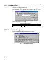
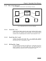
1.2 System Configuration
The following three methods are available for connecting the robot controller to
the personal computer:
(1) RS232C connection
(2) Ethernet connection
(3) Modem connection
Each of these connection methods is explained below.
1-1
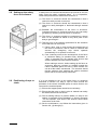
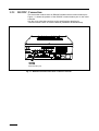
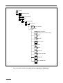
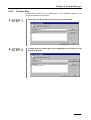
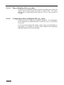
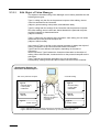
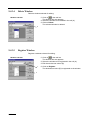
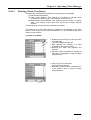
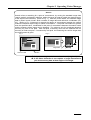
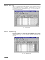
1.2.1 RS232C Connection
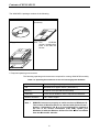
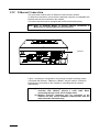
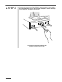
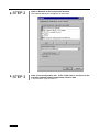
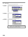
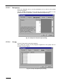
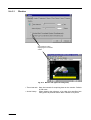
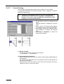
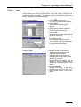
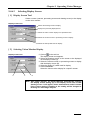
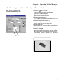
This connection method uses an RS232C standard serial communication port.
Figure 1-1 shows the position of the RS232C communication port on the robot
controller.
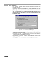
Use the cross cable that conforms to the specifications described in
“Communication Cable” of Owner’s Manual (Installation & Maintenance).
Communication port
Fig. 1-1 RS232C Communication Port on Robot Controller
1-2
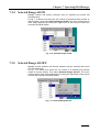
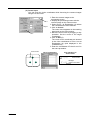
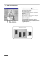
Chapter 1 Outline of Personal Computer Teaching System
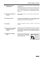
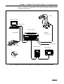
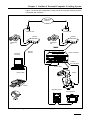
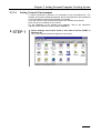
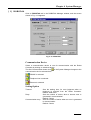
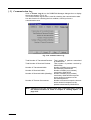
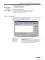
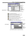
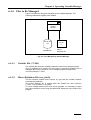
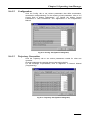
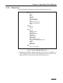
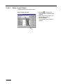
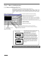
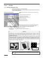
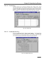
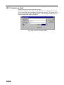
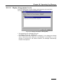
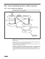
Figure 1-2 shows the configuration of the personal computer teaching system
connected with RS232C.
Robot
Personal computer
RS232C cable
Robot controller
Printer cable
Between
the main body
Power cable
Printer
Operating panel
Teach pendant
CD-ROM
Fig. 1-2 Configuration of Personal Computer Teaching System Connected with RS232C
1-3
1.2.2 Ethernet Connection
This connection method uses an Ethernet communication network.
To effect this connection, ensure that the personal computer is compatible with
Ethernet and can be connected to the network.
The robot controller must be equipped with an Ethernet board (option).
Note: Refer to “Ethernet Board” in Owner’s Manual (Installation &
Maintenance) regarding Ethernet specifications.
Ethernet
Fig. 1-3 Location of Ethernet Board
Figure 1-4 shows the configuration of a personal computer teaching system
connected with Ethernet. 10Base2 or 10BaseT may be used for connection.
Determine the connection to the network by consulting with the network
administrator.
Notes: (1) When directly connecting a personal computer and robot
controller with 10BaseT, prepare a cross cable. When
connecting through a hub, use a straight cable.
(2) Multiple personal computers may be connected to the
network, but they cannot establish communication with the
robot controller simultaneously.
1-4
Chapter 1 Outline of Personal Computer Teaching System
1. Example 1 - Cross cable
Personal computer
Communication cross cable
Robot
Robot controller
Printer cable
Cable to the
main body
Power cable
Printer
Operating panel
Example 2 - Straight cable
Teach pendant
Straight cable
communication
Personal computer
Robot
Straight cable
communication
Printer cable
Straight cable
communication
Cable to the
main body
Robot controller
Power cable
Printer
Operating panel
Teach pendant
Fig. 1-4 Configuration of Personal Computer Teaching System Connected with Ethernet
1-5
1.2.3 Modem Connection
This subsection describes how to connect the robot with a remote personal
computer through the telephone by connecting a modem to the RS232C
communication port of the robot controller.
This connection method requires a serial communication port obtained by
connecting a modem to the personal computer.
Figure 1-5 shows the RS232C communication port of the robot controller to
which the modem is connected.
Refer to “Communication Cable” in Owner’s Manual (Installation &
Maintenance) regarding the communication cable for connection with a
modem. Select the cable that meets the specifications of the modem to be
used.
Robot
Modular wall
Robot controller
Cable to
the main body
Modem
RS232C
Power cable
Operating panel
Teach pendant
TEL
Fig. 1-5 Connection of the Robot Controller and Modem
1-6
Chapter 1 Outline of Personal Computer Teaching System
Figure 1-6 shows the configuration of the personal computer teaching system
connected with a modem.
Telephone
Network
Modular wall
Modular wall
Modem
Modem
Telephone
set
Telephone
set
Robot controller
Personal
computer
Cable to
the main body
Power cable
Robot
Printer cable
Printer
Operating panel
Teach pendant
Fig. 1-6 Configuration of Personal Computer Teaching System Connected with a Modem
1-7
1.3 Security
For data control security reasons, the personal computer teaching system
divides users into two levels to limit operation and information that can be can
accessed.
Higher order users are identified via password to allow access to higher
operation and information.
1.3.1 User Level
Table 1-1 indicates user levels.
Table 1-1 User Level
User level
Operator
Programmer
Description
Not allowed to modify contents. No password is required.
May modify contents except system critical items. Password is
required for access. For initial access enter an optional
password. This will be automatically registered as the
password.
Note: The range of accessible information varies with the user level. If
necessary information is not printed by printing operation, select
Re-Login from the Tools menu of the System Manager to change
the user level and proceed with printing again. For information
regarding Re-Login, refer to “4.3.3 Re-Log In”.
1-8
Chapter 1 Outline of Personal Computer Teaching System
1.3.2 Password
The user will be prompted to enter a password in the following cases:
• When starting WINCAPSII
• Immediately upon selecting Set in each Manager
• Immediately upon selecting Print in each Manager
Once correctly entered, the password will not be requested before the session
is over.
When a password is required, the Password window as shown in Fig. 1-7 will
appear. Select the user level from the popup menu and enter the password
correctly as required. Press OK to proceed.
When using the system for the first time, enter an optional password. It will be
automatically registered.
Note: A distinction is made between upper and lower case letters in the
password.
Fig. 1-7 Password
To change the user level during processing, select Re-Login from the Tools
menu of the System Manager, change the user level and enter the password
again.
Fig. 1-8 Re-Login
1-9
Fig. 1-9 Password
Note: The user level is referred to when opening dialogue boxes.
To change the user level when the dialogue box has already been
opened by Set or Print command, close the dialogue box once,
and reopen it. The new user level will then be enabled.
1-10
Chapter 2
Setting Personal
Computer Teaching
System
This chapter describes how to connect and set
the personal computer teaching system.
Chapter 2 Setting Personal Computer Teaching System
2.1 Installing WINCAPSII Software
Install the WINCAPSII software on the personal computer to use the personal
computer teaching system.
Note (1): If the WINCAPSII software is already installed on the computer,
first uninstall the existing WINCAPSII software and then
reinstall it. For uninstall procedure, refer to “2.1.2 Uninstall”.
Note (2): Always install or uninstall the software after quitting all the
applications currently running. Shared components in
operation cannot be installed or uninstalled. If a shared
component that WINCAPSII is to use is being used by another
application, the install/uninstall process may fail.
Note (3): During installation of WINCAPSII, the message "Error has occurred
during file copying" may appear depending upon the PC
environments. This is because any other application is using the file
to which WINCAPSII is attempting to overwrite. Ignore the message
and continue installation.
2-1
2.1.1 Installation Procedures
Install the WINCAPS II according to the following procedure.
"STEP 1
Terminate all the currently running applications.
"STEP 2
Insert the WINCAPS II CD-ROM in a CD-ROM drive of your personal
computer.
Denso NetwoRC screen appears. Select “Install WINCAPS II” from the
menu.
If the screen does not appear, proceed to the STEP 3.
Note: f you install the WINCAPS II from the floppy disks, proceed
to the STEP 3.
"STEP 3
Click Start at Windows 95 and then click Run. Type the WINCAPS II
installer name in the Open box and click OK.
Drive E is for CD-ROM (Example)
Note: When loading software from floppy disks, insert DISK-1 into
a floppy disk drive and then select Setup.exe file.
2-2
Chapter 2 Setting Personal Computer Teaching System
"STEP 4
Click on OK in the WINCAPSII Setup window to start the WINCAPSII
Setup program.
"STEP 5
The directory where WINCAPSII will be installed is indicated at
Directory.
button to start setup. Proceed to STEP 13.
If OK, click on
To change the directory (not recommended), click on Change
Directory.
2-3
"STEP 6
2-4
Enter a desired directory for installation. Click on OK to start
Installation.
Hereafter, proceed with your operation interactively according to the
messages displayed on the screen.
Chapter 2 Setting Personal Computer Teaching System
"STEP 7
Installation starts and the progress is indicated via a bar graph.
"STEP 8
When installation is completed, the following message will appear on
the screen. Click on OK.
"STEP 9
Restart Windows 95.
WINCAPSII is then ready for use.
2-5
2.1.2 Uninstall
Note: Always quit all the applications currently running before you install
or uninstall software. Shared components, if they are running,
cannot be installed or uninstalled. If a shared component that
WINCAPSII is to use is being used by another application, the
install/uninstall process may fail.
"STEP 1
Click on Start at Windows 95 and select and open Control Panel from
the Settings menu.
"STEP 2
Double click on Add/Remove Programs in the Control Panel window.
2-6
Chapter 2 Setting Personal Computer Teaching System
"STEP 3
The dialogue box for Add/Remove Programs Properties appears on
the screen. Click on Install/Uninstall tab and select WINCAPSII.
"STEP 4
Click on Add/Remove .... .
"STEP 5
Click on Yes in the Application Removal dialogue box. (All nonshared components are deleted.)
2-7
"STEP 6
Uninstall begins.
If the Shared Component window appears in the middle of the screen,
click on Remove None. (Shared components are not deleted.)
"STEP 7
Upon completion of uninstall, a dialogue box for confirming
completion of processing will appear on the screen. Click on OK.
"STEP 8
Upon completion of uninstall, restart Windows 95.
2-8
Note: Files created by WINCAPSII (such as *.pac, *.ini, etc.) are not
deleted by uninstall operation. Delete files manually as
needed.
Chapter 2 Setting Personal Computer Teaching System
2.2 How to Connect Personal Computer and
Controller
This section describes each of the three types of connections between the
personal computer and the controller.
Note: Always turn both the personal computer and the controller OFF
before proceeding with connection work. Otherwise the equipment
may be damaged.
2.2.1 RS232C
This subsection describes RS232C connection. Use the COM2 port on the
robot controller for communication with the personal computer.
For connection between the computer and other peripheral equipment, refer to
respective instruction manuals.
2.2.1.1
Connecting Cable
"STEP 1
Connect an RS232C communication cross-cable to the robot
controller. Insert it securely in the controller and tighten the screws.
Connection of Robot Controller and
RS232C Communication Cable
2-9
"STEP 2
Connect the other end of the RS232C communication cross-cable to
the communication port on the personal computer. Insert it securely
in the computer and tighten the screws.
Connection of Personal Computer and
RS232C Communication Cable
2-10
Chapter 2 Setting Personal Computer Teaching System
2.2.1.2
Setting Robot Controller
Set up the robot controller to use the RS232C port for the personal computer
teaching system. Make this setting using the teaching pendant.
"STEP 1
Press F6 Set on the teaching pendant basic screen.
The Settings (Main) window will appear on the screen.
2-11
"STEP 2
Press F4 Set Com.
The Communications Setting Menu appears on the screen.
"STEP 3
Press F2 Serial IF.
The Set RS-232C window appears on the screen.
"STEP 4
Select COM2 and press F5 Change.
The Select Transmission Rate window appears on the screen.
2-12
Chapter 2 Setting Personal Computer Teaching System
"STEP 5
Select the transmission rate and press OK.
The screen returns to the Set RS-232C window.
"STEP 6
Check the display contents and press OK.
The set transfer rate becomes valid.
The screen returns to the Communications Setting Menu window.
2-13
"STEP 7
Press F1 Permit. in the Communications Setting Menu window.
The Communication Permission Settings window appears on the screen.
"STEP 8
2-14
Select COM2 and press F5 Change.
The Change Permission Settings window appears on the screen.
Chapter 2 Setting Personal Computer Teaching System
"STEP 9
Select the necessary permission settings.
The meanings of the permission settings are as follows:
⋅ Disable: Communication port is not used.
⋅ Read only: Personal computer is enabled to read the robot controller
data. It is not allowed to send data to the robot controller.
⋅ Read/Write: Data exchange is allowed between the personal computer
and robot controller.
When creating a program, select Read/Write.
When supervising only variables or I/O values by automatic operation of a
ready program, select Read only.
Upon making a selection, press OK.
The screen returns to the Communication Permission Settings window.
Note: You cannot select Read/Write Enabled for both RS232C and
Ethernet simultaneously.
2-15
"STEP 10
Check the display contents and press OK.
The permission setting is enabled.
The screen returns to the Communications Setting Menu window.
"STEP 11
2-16
Press Cancel twice.
The display returns to the basic screen.
Chapter 2 Setting Personal Computer Teaching System
2.2.1.3
Setting Personal Computer
Set the personal computer to enable the installed WINCAPSII software to
communicate with the robot controller. Make this setting at your computer.
"STEP 1
Start the System Manager from Programs by clicking on Start at
Windows 95.
The System Manager starts up and the System Manager window appears
on the screen.
Note: For the method of starting System Manager, refer to “3.1
Starting Personal Computer Teaching System” on page 3-1.
"STEP 2
Click on Set communication button
.
The ROBOTalk Manager starts up and the ROBOTalk Manager window
appears on the screen.
If a password has not been input, the Password dialog box will appear on
the screen. Enter the password. For the method of entering a password,
refer to “1.3.2 Password”.
Setting communication
"STEP 3
Click on the ROBOTalk tab.
The ROBOTalk Manager window will change as follows:
2-17
"STEP 4
Select RS232C(R) in the Communication Device column.
Set the data as shown below in the Optional Settings column.
Timeout
: 4000 msec
Retry
: 5 times
Communication retry : 5 times
"STEP 5
Click on RS232C tab.
The ROBOTalk Manager window will change as follows:
Select a communication port to use on the personal computer in the COM
Port column. Select it according to the specifications of the personal
computer.
For the Baud Rate column, select the same speed as is set for the robot
controller.
"STEP 6
Click on OK.
The ROBOTalk Manager window closes.
This completes the communication settings for the personal computer.
2-18
Chapter 2 Setting Personal Computer Teaching System
2.2.1.4
Connecting to the Robot Controller
If RS232C is selected as the communication device in the preceding item
for
2.2.1.3 “Setting Personal Computer”, the Setting communication button
the system manager will appear as shown below:
Fig. 2-1 Setting communication Button (RC232C)
When the respective managers are started from the system manager button
will appear on each manager button.
and set for connection, corner marks
For information on how to connect each manager, read the descriptions on the
operation of each manager in chapters 5 through 10.
2-19
2.2.2 Telephone Line
A telephone line needs to be set up for the personal computer and robot
controller for telephone communication.
2.2.2.1
Connecting Modem
To make connection via a telephone line, a modem must be installed.
To do this, use Modems on the Control Panel in Windows.
For the connection of a personal computer and modem, refer to the respective
instruction manual as it varies depending on the hardware.
2-20
Chapter 2 Setting Personal Computer Teaching System
2.2.2.2
Setting Robot Controller
"STEP 1
Press F6 Set on the basic screen of the teach pendant.
The Settings (Main) window will appear on the screen.
"STEP 2
Press F4 Set Com.
The Communications Setting Menu window appears on the screen.
2-21
"STEP 3
Press F3 Modem.
The Set Modem window appears on the screen.
"STEP 4
Select the communication port of the controller to which the modem
is
connected.
Select COM2 and press OK.
The following system message appears.
"STEP 5
Check the system message and press OK.
2-22
Chapter 2 Setting Personal Computer Teaching System
2.2.2.3
Setting Personal Computer
"STEP 1
Click on Setting communication button
of the System Manager.
The ROBOTalk Manager starts and the ROBOTalk Manager window
appears on the screen.
If a password is not yet input, the Password dialog box appears. In this
case, input the password. For the method of entering a password, refer to
“1.3.2 Password”.
"STEP 2
Double-click on the Telephone tab.
The ROBOTalk Manager window will change as follows:
"STEP 3
Enter each item by referring to the descriptions in Table 2-1 and click
on OK.
Table 2-1 Telephone Optional Setting
Items
Description
Modem
Modem used for remote connection
Location
Information of current location (Information on the
dialing party)
TEL Number
Telephone number of the other party (called party)
Automatic Answer
Set Modem
Set Dial
Call receiving side will be checked.
Makes detailed modem settings.
Modifies or adds location information.
2-23
2.2.2.4
Connecting to Robot Controller
Upon selecting the telephone line for the communication device as a result of
the setting operation in the preceding item “2.2.2.3 Setting the Personal
of the System Manager will
Computer, the Setting communication button
appear as shown below:
Fig. 2-2 Setting communication Button (Telephone)
When the respective managers are started from the system manager button
will appear on each manager button.
and set for connection, corner marks
For information on how to connect each manager, read the descriptions on the
operation of each manager in chapters 5 through 10.
2-24
Chapter 2 Setting Personal Computer Teaching System
2.2.3 Ethernet
Setting is required to enable communication between the personal computer
and the robot controller by connecting them via Ethernet.
2.2.3.1
Connecting Cable
The personal computer and the robot controller need to be connected via an
Ethernet network. For information regarding this connection, refer to “1.2.2
Ethernet Connection”.
2-25
2.2.3.2
Setting Robot Controller
Set the robot controller to use the Ethernet port for the personal computer
teaching system. Make this setting using the teach pendant.
Specify the permission setting.
In the present stage, you cannot set the IP address (your IP address) and gate
address (gateway IP address).
"STEP 1
Press F6 Set on the basic screen of the teach pendant.
The Settings (Main) window appears on the screen.
2-26
Chapter 2 Setting Personal Computer Teaching System
"STEP 2
Press F4 Set Com.
The Communications Setting Menu window appears on the screen.
"STEP 3
Press F1 Permit.
The Communication Permission Settings window appears on the screen.
"STEP 4
Select Ethernet and press F5 Change.
The Change Permission Settings window appears on the screen.
2-27
"STEP 5
Select Read/Write.
The meanings of the permission settings are as follows:
When using Ethernet, select Read/Write.
• Disable: Communication port is not used.
• Read only: Personal computer is enabled to read the robot controller
data. It is not allowed to send data to the robot controller.
• Read/Write: Data exchange is allowed between the personal computer
and robot controller.
Upon making section, press OK.
The screen returns to the Communication Permission Settings window.
Note: You cannot select Read/Write Enabled for both RS232C and
Ethernet simultaneously.
2-28
Chapter 2 Setting Personal Computer Teaching System
"STEP 6
Check the display contents and press OK.
The permission setting becomes valid.
The screen returns to the Communications Setting Menu window.
2-29
"STEP 7
Press F4 Set Address.
The Set Controller IP Address window appears.
"STEP 8
Press F5 Change and enter a required address.
In the example here, IP Address is set to 192.168.0.1 and Subnet Mask to
255.255.255.0.
"STEP 9
Press Cancel twice.
The display returns to the basic screen.
2-30
Chapter 2 Setting Personal Computer Teaching System
2.2.3.3
Setting Personal Computer
"STEP 1
Click on the Setting communication button
of the System
Manager.
The ROBOTalk Manager starts and the ROBOTalk Manager window
appears on the screen.
If a password is not yet input, the Password dialog box appears on the
screen. In such a case, enter the password. For information regarding how
to enter a password, refer to “1.3.2 Password” on page 1-9.
"STEP 2
Click on the Ethernet tab.
2-31
"STEP 3
Enter data in Controller IP, Connection Port, and Local Port at
Optional Setting and then click on OK.
Controller IP is the IP address of the party at the destination. Match it to
the desired party for connection. (For example, an IP address such as
192.168.0.1).
Communication Port is the local port number of the opposite party at
destination. Match it to the desired party for connection. (For example,
4112).
Local Port is the port number for own use. In principle it should be over
1024 and may be freely set if it does not infringe on others within the same
network.
Note: The following relationships have to be established for the
Ethernet connection: Own Connection Port = Local Port of
the other party.
Own Local Port = Connection Port of the other party
If connection is limited to the ROBOTalk Manager and robot
controller, the local port will be automatically replaced with
an appropriate value by setting zero (0) in the Local Port on
the ROBOTalk Manager side.
Table 2-2 Ethernet Optional Setting Option
Items
Controller IP
Connection Port
Local Port
2-32
Description
IP address or host name of the opposite party
Fixed at 4112
Fixed at 0
Chapter 2 Setting Personal Computer Teaching System
2.2.3.4
Setting Network Environment
To effect connection by Ethernet, it is necessary to set up Windows 95. The
network environment setting procedures will be described here preconditioned
on the fact that the network card (adapter) is installed,
First, add TCP/IP to the protocol to be used in the network environment.
Next, set up an IP address for the TCP/IP.
For the installation of the network card (adapter), refer to the instruction
manuals of the respective network cards (adapters).
"STEP 1
Select Settings and Control Panel in this order from the START of
Windows 95.
The Control Panel window will appear on the screen.
2-33
"STEP 2
Click on Network in the Control Panel window.
The Network dialog box will appear on the screen.
"STEP 3
Click on the Configuration tab. If the TCP/IP item is not found in the
currently installed network components, click on Add.
If TCP/IP exists, jump to STEP 6.
2-34
Chapter 2 Setting Personal Computer Teaching System
"STEP 4
The Select Network Component Type dialog box appears on the
screen. Select Protocol click the type of network component you
want to install and click on Add.
"STEP 5
The Select Network Protocol dialog box will appear on the screen.
Select Microsoft from Manufacturers. Select TCP/IP in Network
Protocols that appears on the right-hand side and click on OK.
This results in the addition of the TCP/IP protocol.
2-35
"STEP 6
2-36
Again select the Configuration tab in the Network dialog box. Then,
select the TCP/IP item from the following installed network
components and click on Properties.
Chapter 2 Setting Personal Computer Teaching System
"STEP 7
Select IP Address tab and click to specify an IP address. Then input
required data in IP Address and Subnet Mask.
For the actual values of the IP address and subnet address, inquire to the
network administrator in charge of the pertinent network.
If the network is local (for example, an environment for connecting the
personal computer and the robot controller only), the IP address can be set
as desired. Therefore, the IP address will be tentatively set here to
192.168.0.1 and the subnet address to 255.255.255.0.
Click on OK and the IP address setting is completed.
Note (1): When making connection to a wide area network (for
example an in-house network), always inquire to the
network administrator before setting the IP address and
subnet mask.
If an IP address used for the local area network is
connected to the wide area network (for example the inhouse network) without first invalidating it, confusion
may be occur in the connected network.
Note (2): No redundant IP addresses are allowed within the same
network. When making a connection to a widely shared
network, care should be taken not to allow an IP address
to be redundant with another terminal. The following are
examples of IP addresses that have the least probability
of redundancy with another terminal:
192.168.0.2 to 192.168.0.xxx (xxx represent 003 to 999.)
2-37
"STEP 8
2-38
Lastly select Identification tab and input a computer name and a
workgroup.
The computer name may be entered as desired, but give it the same name
here as the login name entered at Windows startup.
The work group will be tentatively made to read fa.denso.co.jp.
Click on OK.
This completes the network environment setting.
Refer to the Windows 95 instruction manual or ask the network
administrator for further information.
Chapter 2 Setting Personal Computer Teaching System
2.2.3.5
Connecting to Robot Controller
If Ethernet is selected for the communication device according to “2.2.3.3
Setting Personal Computer” and “2.2.3.4 Setting the Network environment”
of the System
thus far described, the Setting communication button
Manager will be displayed as shown below:
Fig. 2-3 Setting Communication Button Display (Ethernet)
When the respective managers are started from the system manager button
appear on each manager button. For
and set for connection, corner marks
information regarding how to connect each manager, read the descriptions on
the operation of each manager in chapters 5 through 10.
2-39
Chapter 3
Starting Teaching
System and
Knowing Each
Manager
This chapter describes the procedures for
starting and terminating the personal computer
teaching system and outlines the functions of
each Manager.
Chapter 3 Starting Teaching System and Knowing Each Manager
3.1 Starting Personal Computer Teaching
System
Let’s start and run the WINCAPS II on your personal computer in order to
input, edit, and verify the robot operation programs.
Starting the System Manager
DENSO application software WINCAPS II for personal computer teaching
system consists of the following function modules.
l PAC Program Manager
l Variable Manager
l DIO Manager
l Arm Manager
l Vision Manager
l Log Manager
l Communication Setting Manager
All these function modules are controlled by the System Manager. That is, all
the functions of WINCAPS II should be called from the System Manager before
they are implemented.
To use the personal computer teaching system, start the System Manager first.
"STEP 1
Click Start at Windows 95. Point to Programs, and then click System
Manager in the WINCAPS II folder.
3-1
"STEP 2
The WINCAPS II Information window appears. Read the information and
click OK.
Note: If you click the check box “Omit this message” at the lower
left of the screen, the above window will not appear from the
next startup operation.
"STEP 3
The License Information window does not appear until you enter your
license key. Enter User ID printed in the license card and click OK.
Note: For detail on entering the license key, refer to 4.5.3 License
Key. Once you enter your license key, this window will not
appear from the next startup operation.
"STEP 4
When starting the System Manger after initial installation of WINCAPS II,
create a program bank.
Note: When the dialog box “Create Program Bank” appears,
specify the files to be used in the program bank according to
the procedure described in “5.6.2.3 Updating Program
Bank”.
"STEP 5
You need to create a project when activating the WINCAPS II for the first
time after installation, because no system project has been defined.
Note: If a dialog box “Create New Project” appears, create a project
for the robot to be connected by referring to “4.2.1. New
Project”.
3-2
Chapter 3 Starting Teaching System and Knowing Each Manager
"STEP 6
When the WINCAPS II is activated the second time and after, the dialog
box "Open Project" appears. Select a desired project. The default is the
previously used project.
"STEP 7
The Password window appears. Select the user level from the pop-up
menu, enter the password if necessary, and then click OK.
Note: For the password, refer to “1.3.2 Password”.
"STEP 8
The dialog box appears with the message “Connect with the controller? ”.
Click No.
The System Manager is activated and the System Manager window
appears. The icon buttons are used to activate the modules classified by
the function.
To use each of these function modules, click the required module icon or
select the required function from the command menu in the System
Manager window.
3-3
3.2 Terminating Personal Computer
Teaching System
To terminate the personal computer teaching system, you need to terminate
the programs of both personal computer and Robot Controller.
3.2.1 Terminating Personal Computer
"STEP 1
Clicking the close box at the upper right of the System Manager window
will terminate all the software for WINCAPS II running on your personal
computer.
"STEP 2
Terminate the Windows 95 and turn off the personal computer, if
necessary.
3.2.2 Terminating Robot Controller Connected with Personal
Computer
"STEP 1
Turn off the power switch.
Power switch of the Robot Controller
3-4
Chapter 3 Starting Teaching System and Knowing Each Manager
3.3 Function Outline of Each Manager
The application software for the personal computer teaching system consists of
the various Managers classified by their functions. The following table lists the
function outline of each Manager.
Manager
System Manager:
Totally controls the
personal computer
teaching system.
Functions
Reference
1.
Starts each Manager.
4.1.2
2.
System project management
4.1.3, 4.2
l Creates a new project.
l Opens an existing project.
l Saves a project.
l Transfers a project.
l Terminates the personal computer teaching system.
PAC Program
Manager:
3.
Sets the communication devices and their operating
conditions.
4.3.1
4.
Changes password.
4.3.2
5.
Reads data from or records data onto the floppy disk.
4.3.4, 4.3.5
6.
Enters the license key.
4.5.4
1. File operations
5.2
l Creates a new program project.
Totally supports the
program
development using
the robot language.
l Opens an existing program project.
l Saves a program project.
l Sets the parameters used for the project.
l Receives/transfers the program data.
l Prints program data.
l Creates an executable program.
l Terminates PAC Program Manager.
2. Program editing
5.3
l Edits program.
l Searches and replaces character-string in program.
l Jumps to another line.
3. Program Management
5.4
l Creates a program and adds it to the project.
l Saves a program file with another name.
l Adds an existing program to the project.
l Removes a program from the project.
l Imports and exports a program.
l Changes the order of displayed programs.
4.
Makes various settings for PAC Program Manager.
5.6
5.
Uses the program bank.
* An existing program can be registered or used as a
part.
5.6.2
6.
Command builder
* Supports proper inputs of commands and arguments in
program editing.
5.6.3
3-5
Manager
Functions
Reference
Variable Manager:
1.
Monitor the variables.
6.4
Backs up or
monitors the
variables used by
the Robot
Controller.
2.
Operates the variables data.
6.1.3
3.
Prints the variables table.
6.2.6
4.
Backs up data in the variables table.
6.2.4
5.
Creates a macro definition file for variables.
6.2.7
6.
Transfers the variables table between personal
computer and the Controller.
6.2.5
7.
Sends messages via RS232C.
6.5.2
1.
Monitors the I/O status.
7.4.3
2.
Changes the I/O status according to dummy input.
7.4.4
3.
Prints the I/O table.
7.2.6
4.
Backs up the I/O table data.
7.2.3
5.
Creates the macro definition file for assigning I/O data.
7.2.7
6.
Transfers the I/O table between the personal computer
and the controller.
7.2.5
1.
Monitors the current position of robot arm.
8.4
2.
Views the work number and the tool number.
8.5
3.
Gets the current position into pose data.
6.4.4
4.
Simulates robot movements.
8.6.2
5.
Sets the parameters related with the robot arm.
8.6.1
6.
Defines the tool coordinate system.
8.6.1
7.
Defines the work coordinate system.
8.6.1
8.
Defines the area.
8.6.1
9.
Object tree
* Defines the object drawn in the robot display.
8.6.3
DIO Manager:
Monitors the I/O
status and sets
dummy I/O data
Arm Manager:
Monitors the current
robot arm position,
work number, and
tool number.
10. Converts pose data.
* Type conversion among P, J, T type data
3-6
8.6.4
Chapter 3 Starting Teaching System and Knowing Each Manager
Manager
Vision Manager:
Supports creation of
vision program
using PAC
language.
LOG Manager:
Functions
Reference
1.
Opens the image data.
9.2.7
2.
Connects with the Robot Controller.
9.3.1
3.
Creates a macro definition file for vision.
9.4.2
4.
Displays the camera image.
9.4.6
5.
Edits the window.
9.4.3
6.
Edits the search model.
9.4.4
7.
Executes the camera CAL.
9.4.5
8.
Uses the image analysis tool.
9.4.6
1.
Browses log data.
10.1
l Error log
Gets the log (robot
operation record)
into personal
computer and
manages the log
data.
l Operation log
l Control log
l Communication log
2.
Creates new log file.
10.2.1
3.
Receives the log data from the controller.
10.2.5
4.
Prints the log.
10.2.6
5.
Searches and replaces the character strings.
10.3.7
6.
Control log
(Records the control log so that the operation can be
replayed using the Arm Manager.)
10.4.3
7.
Displays the version of each robot controller part.
10.6.3
3-7
Chapter 4
System Manager
This chapter describes the function and operation
of the System Manager, which constitutes the
nucleus of the WINCAPSII software used in the
personal computer teaching system.
Chapter 4 System Manager
4.1 Outline of System Manager
4.1.1 Outline of Functions
WINCAPSII application software for the personal computer teaching system
consists of various managers with their own respective functions, as stated
below:
• System Manager:
• PAC Program Manager:
• Variable Manager
• DIO Manager:
• Arm Manager:
• Vision Manager:
• Log Manager
Overall control (including communication setting)
Program editing control
Variable information control
I/O information control
Robot action information control
Vision information control
Log information control
The System Manager makes controls the overall data files controlled by other
managers, as a system project. It also controls communication setting and
password setting.
Respective managers can be used by calling them from the System Manager.
To start the System Manager, select the System Manager program with the
Start key of Windows. When started, the main screen of WINCAPSII and the
System Manager window appear on the screen.
For starting procedure details, refer to Chapter 3 “3.3.1 Starting System
Manager” in this manual.
Displays object of system
manager operation
Displays the content of
system manager operation
Status bar
Fig. 4-1 WINCAPSII Main Screen
4-1
4.1.2 Tool Bar
Tool bar
Communication
set button
PAC Program
Manager button
Variable Manager button
DIO Manager
button
Arm Manager
button
Log Manager button
Vision Manager
button
Fig. 4-2 Tool Bar
PAC Program Manager Button
Click on this button to start the PAC Program Manager.
For descriptions on the operating procedures of the PAC Program Manager,
refer to Chapter 5 “Operating PAC Program Manager” and Chapter 3 “3.5
Entering and Editing Programs” in this manual.
When the PAC Program Manager is connected to the Robot Controller, the
button icon changes to
.
Variable Manager Button
Click on this button to start the Variable Manager.
For Variable Manager operating procedures, refer to Chapter 6 “Operating
Variable Manager” and Chapter 3 “3.14.1 Starting Variable Manager” in this
manual.
When Variable Manager is connected to the Robot Controller, the button icon
display changes to
.
DIO Manager Button
Click on this button to start DIO Manager.
For the procedures for operating DIO Manager, refer to Chapter 7 “Operating
DIO Manager” and Chapter 3 “3.13.1 Starting DIO Manager” in this manual.
When the DIO Manager is connected to the Robot Controller, the button icon
changes to
.
Arm Manager Button
Click this button to start the Arm Manager.
For the procedures for operating Arm Manager, refer to Chapter 8 “Operating
Arm Manager.”
When the Arm Manager is connected to the Robot Controller, the button icon
changes to
.
4-2
Chapter 4 System Manager
Vision Manager Button
Click on this button to start the Vision Manager.
For Vision Manager operating procedures, refer to Chapter 9 “Operating Vision
Manager” in this manual.
When the Vision Manager is connected to the Robot Controller, the button icon
display changes to
.
Log Manager Button
Click on this button to start the Log Manager.
For Log Manager operating procedures, refer to Chapter 10 “Operating Log
Manager” in this manual.
When the Log Manager is connected to the Robot Controller, the button icon
display changes to
.
Set Communication Button
Click this button to set communication.
To set Communication, refer to Chapter 4 “4.3.1 Set Communication” and
Chapter 2 “2.2 How to Connect Personal Computer and Controller” in this
manual
“Set Communication” button display changes for each selected communication
device:
When not in connection
Connected via RS232C
Connected by telephone line via modem
Connected by TCP/IP via Ethernet
4-3
4.1.3 System Project Management
When developing a program using WINCAPSII, in addition to the program
data, a number of data such as variables and parameters that accompany the
operation of the program have to be processed.
With WINCAPSII, the System Manager manages programs and the related
groups of data, in terms of a system project. This management information is
stored in the system project file (SPJ file). The system project file controls all
information needed for operating a unit of the robot.
4.1.3.1
WINCAPSII-Generated Files
Fig. 4-3 shows the relationship among the files, which are generated and
managed by their respective WINCAPSII managers, for the purpose of data
storage.
Files other than the program bank file are placed in the project folder,
immediately after a system project is newly created. The program bank file is
placed in the folder named ProgramFiles Wincaps2, if the default exists where
WINCAPSII application is installed.
For example, if a project named IRA-0000, which appears initially by default is
generated, this project is generated in the folder named ProgramFiles Wincaps2 by
default. Files other than the program bank files are placed in the project folder
named IRA-0000. Fig. 4-4 shows the position of files generated and managed
by WINCAPSII.
Note: Each Manager has a current folder. These Managers output their
respective control files to their current folders.
Immediately after newly creating a system project, all the
Managers use the same current folder.
When respective Managers newly create files, the current folder
will not be changed, unless the folder is changed.
If the current folder is changed, a reference path for the input file
will be required using #INCLUDE statement and other file input
commands.
4-4
Chapter 4 System Manager
System Manager
(including
communication
setting)
∗.SPJ
Program
Manager
System project file
(including communication setting)
Variable
Manager
DIO
Manager
Arm
Manager
Vision
Manager
Log
Manager
∗.VAR
∗.DIO
∗.ARM
∗.VIS
∗.LOG
Variable
file
DIO file
Arm file
Vision file
Log file
∗.BNK
∗.PPJ
var_tab
.h
Program
bank file
Program
project file
Micro
definition file
arm_cnf
.h
∗.MDL
Model
data file
com_chf
.h
Arm configuration
macro definition file
∗.LNK
*.LNK
∗.PAC
Program file
dio_tab
.h
Make file
∗.RIC
Intermediate file
Micro
Definition file
dio_cnf
.h
Configuration macro
definition file
∗.MAP
Cross
reference file
Configuration macro
definition file
vis_tab
.h
Macro
definition file
vis_chf
.h
Configuration
macro
definition file
∗.NIC
Execution
format file
∗.bmp
Bit map file
Fig. 4-3 Files Generated and Managed by WINCAPSII
4-5
Desktop
Personal computer
3.5 inch FD (A:)
(C:)
Program files
Wincaps 2
∗BNK
Program bank file
Ira-0000
∗SPJ
System project file
(including communication setting)
∗.LOG
Log file
∗.VIS
Vision file
∗MDL
Model data file
∗.ARM
Arm file
∗.DIO
DIO file
∗.VAR
Variable file
∗.PPJ
Program project file
∗PAC
Program file
∗.h
Macro definition file
Fig. 4-4 Position of Files to Be Generated and Managed by WINCAPSII
4-6
Chapter 4 System Manager
4.1.3.2
File Management by System Manager
The System Manager manages the relation of data files generated by other
groups of Managers. The system project file (*.spj) generated by the System
Manager has data files which are referenced by each Manager.
When starting each Manager, the System Manager specifies the reference
data files for the started Manager. Therefore each Manager can use the groups
of programs or variables that differ by project, without confusion.
The Set Communication is a function incidental to the System Manager and,
therefore, it does not have its own data file. The Set Communication
information is included in the system project file.
The system project file has an extension code “.SPJ”.
4-7
4.1.4 Menu List
The System Manager command menu has the following tree structure:
File
New Project
Open Project
Save Project
Save Project As
Transfer Project
Project information
Exit
Tools
Set Communication
Change Password...........(Programmer Level)
Re-Login
Read FD Images
Write FD Images
Window
PAC Manager
Variable Manager
DIO Manager
Arm Manager
Vision Manager
LOG Manager
Help
License Key
System Extension
About System Manager
Fig. 4-5 System Manager Menu Tree
4-8
Chapter 4 System Manager
4.2 File Menu
The System Manager FILE menu contains commands for controlling the
project, besides the command for exiting the System Manager.
Fig. 4-6 File Menu
Note: The New Project and Open Project menu commands are invalid
when any of PAC, DIO Arm, Vision and LOG Managers is
connected.
4.2.1 New Project
This command is used for creating a new system project.
After selecting this command, the Create New Project dialog box appears on
the screen. Input default data, after changing it as may be needed, and click
on OK. If Cancel is clicked, the command closes the box without creating a
project.
Fig. 4-7 Create New Project Dialog Box
4-9
• Robot Series:
• Type:
• Environment:
• Additional Axis:
• Stroke:
• Project Name:
• Folder:
• Output Code:
• Facility Type:
• New Folder:
Select a desired robot series.
Select a robot type from "Robot Series."
Select environment according to the selected robot.
Select whether there is an additional axis.
Displayed for each robot type as required. Select this
item according to the selected robot.
Enter the project name.
Describes a folder for storing the project. You can
select a folder path by clicking the Folder button.
Sets a version of the execution program to be created
according to the version of the connected controller.
Select a facility type. A program library necessary for
the type selected here is automatically added to the
PAC program manager. If Standard is selected,
nothing will be added.
After clicking, the New Folder Window appears. The
new folder can be created by entering the folder name.
Fig. 4-8 New Folder Window
• Details:
After clicking, the Details window appears. Specify, in
this WINDOW box, the default data reference files of the
respective Managers. The default data is created in the
process of Create New Project. Set the respective
reference files using “...” Clicking on Initialize returns
the specified reference file to the default setting. It is
usually not necessary to change the detail setting.
Fig. 4-9 Details Window
4-10
Chapter 4 System Manager
4.2.2 Open Project
This command opens the existing projects.
When this command is specified, the Open project window appears.
Fig. 4-10 Open Project Window
The files that contain the project management information have the extension
file name “.spj”. Select a file having the “.spj” extension for the project name.
or the folder in the display
Click on the Move up one holder level button
box, and you can change the path.
When you click on a file having an “.spj” extension, the file name is entered in
the File name box. Click on Open to opens the project.
To close the dialogue box without opening the project, click on Cancel.
4.2.3 Save Project
This command saves the currently opened project information.
4.2.4 Save Project As
This command stores the currently opened project as another one. All files
used for the current project are copied to the new project.
Note: Do not select “Floppy (A:)” as place saved in.
4-11
4.2.5 Transfer Project
This command transmits the system project data. In the Robot Controller, this
command is used for backing up the data.
Data may be transmitted in a batch, or may be transmitted in parts by selecting
each Manager data from the transmission table.
Note: To transmit data selectively under the control of a manager other
than the System Manager, you can use the Transmit command in
the File menu of each respective Manager.
Fig. 4-11 All Data Batch Transfer Window
4.2.6 Project Information
Displays the set robot type or the project information for each Manager.
Fig. 4-11-1 Project Information Dialog Box
4.2.7 Exit
This command terminates the WINCAPSII application software.
The functional managers opened from the System Manager are simultaneously
terminated.
4-12
Chapter 4 System Manager
4.3 Tools Menu
Fig. 4-12 Tools Menu
4.3.1 Set Communication
When you select “Set Communication” in the Tools menu, the ROBOTalk
Manager dialog appears.
Click on the set communication button
, to display the ROBOTalk Manager
dialog.
The ROBOTalk Manager dialog box is used to set the communication device
and communicating conditions, and to perform service processing of the
communication protocol for the robot. This dialog box is also used to monitor
the communication state and save the communication log.
4-13
Fig. 4-13 ROBOTalk Manager Window
Clicking on the ROBOTalk tab enables you to make settings, as described in
the following section downward.
When all the settings have been completed, click on OK.
When you lick on Cancel, the ROBOTalk Manager dialogue box is closed
without any change of set values.
Press Stop in such cases where you want to interrupt transmission from the
personal computer, no response is returned from the other party, or you want
to stop the ongoing transmission.
Update is a button for confirming the contents until now. Clicking on OK closes
the Communication Manager. Use Update to check the set data without
closing the Communication Manager.
Note: The OK and UPDATE (A) buttons are invalid when one of the PAC,
Variable, DIO, Arm, Vision or LOG Managers is in connection or the
user level is set to “0-Operator”.
4-14
Chapter 4 System Manager
[ 1 ] ROBOTalk
Click on ROBOTalk tab in the ROBOTalk Manager window, and the screen
shown in Fig. 4-14 appears.
Fig. 4-14 ROBOTalk
Communication Device
Select a communication device to use for communication with the Robot
Controller by clicking on a desired device.
in the System Manager changes to the
The Set Communication button icon
communication device selected here.
RS232C is selected.
Telephone line is selected.
Ethernet is selected.
Setting Option
Timeout:
Retry:
Communication retry:
Sets the waiting time, for error judgment when no
response is received from the Robot Controller.
Default: 4000 msec.
Sets the number of retries, when a timeout error is
generated in communication.
Default: 5 times
Sets the number of retries when an error is generated
in communication.
Default: 5 times
4-15
[ 2 ] RS232C
Click on RS232C tab of the ROBOTalk Manager window to display the screen
shown in Fig. 4-15.
Set the required data on this screen to enable connection between the
personal computer and the Robot Controller directly with the RS232C cable.
Fig. 4-15 RS232C
COM Port
Select the communication port to be used on the personal computer. When you
click on the arrow , the options appear in a pull-down menu.
Baud Rate
Select the baud (communication) rate. When you click on the arrow
options appear in a pull-down menu.
, the
Note: The faster the communication speed, the more frequently the
communication error tends to occur.
Parity Bit
Select the parity check bit. Click on the arrow
pull-down menu.
to display the options in a
Data Bit Length
Select the data bit length for communication. Click on the arrow
the options in a pull-down menu.
4-16
to display
Chapter 4 System Manager
Stop Bit Length
Select the stop bit length. Click on the arrow
down menu.
to display the options in a pull-
Normal
Set all RS232C related items to normal settings.
Communication port : COM1
Baud rate
: 19200
Parity bit
: N-No parity
Data bit length
:8
Stop bit length
:1
[ 3 ] Telephone
Click on Telephone tab in ROBOTalk Manager dialogue box to display the
screen shown in Fig. 4-16.
Set the required data on this screen to enable connection between the
personal computer and Robot Controller using a telephone line.
Fig. 4-16 Telephone Tab
Modem
The above dialog box shows the currently selected modem. Click on the arrow
to display the options in a pull-down menu.
By clicking on Modem icon in the control panel, you can select a registered
modem.
For how to use the Modem in the control panel, refer to the instruction manual
for Windows 95.
Location
Select the location where the personal computer is used. Clicking on the arrow
to display the options in a pull-down menu.
You can select a registered location by the following dial settings:
4-17
TEL Number
Enter the telephone number of the other party to which you intend to connect.
Only enter the numerical characters. Hyphen, bracket, or the other signs are
not usable for entry of telephone number.
Automatic Answer
If you put a checkmark in Automatic Answer check box, the personal computer
automatically answer the calls.
Set Modem
This column shows the property of the selected modem.
For details on modem property setting, refer to the instruction manual for
Windows 95.
Set Dial
This column displays the dial property.
For details on dial property setting, refer to the instruction manual for Windows
95.
ONHOOK
Press the ONHOOK button to disconnect the telephone connection.
Note: Connection with a telephone line is possible only when the modem
is installed. For details on modem installation, refer to Chapter 2
“2.2.2 Telephone Line” in this manual.
4-18
Chapter 4 System Manager
[ 4 ] Ethernet
Click on Ethernet tab on the ROBOTalk Manager dialogue box to display the
screen shown in Fig. 4-17.
Set the required data on this screen to enable connection between the
personal computer and Robot Controller using Ethernet.
Fig. 4-17 Ethernet
Controller IP
Enter the IP address or the host name of the opposite station.
Connection Port
Enter the port number of the opposite station. Always set this number to 4112.
Local Port
Enter the port number of the personal computer.
Always set this number to 0 (zero).
4-19
[ 5 ] Communication Log
Click on Comm. Log tab on the ROBOTalk Manager dialogue box to display
the screen shown in Fig. 4-18.
The communication log function is used for checking the communication state.
Use this function for checking the line condition, should you have a
communication error.
Fig. 4-18 Communication Log
Total Number of Transmitted Packets: Total number of packets transmitted
by WINCAPSII
Total Number of Received Packets:
Total number of packets received by
WINCAPSII
Number of Transmitted NAKs:
Number of NAKs (error packets)
transmitted by WINCAPSII
Number of Received NAKs:
Number of NAKs (error packets)
received by WINCAPSII
Number of Received NAKs (Standby): Number of NAKs (error packets)
received by WINCAPSII except the
errors caused in response to the
transmitted packets
Number of Timeout Occurrences:
Number of timeouts except the timeout
errors caused in response to the
packets transmitted by WINCAPSII
Note: If timeout occurs for reasons other than connection failure, extend
the timeout duration as noted in Chapter 4 “Setting Option” on
page 4-15.
4-20
Chapter 4 System Manager
4.3.2 Changing Password (Programmer Level)
To change the password, select Change Password from the Tools menu. The
Changing password window appears.
Fig. 4-19 Changing Password Window
At User Changed to, select the user level whose password is to be changed.
At Old Password, enter the previous password.
At New Password, enter a new password.
At Verify New Password, re-enter the new password for verification.
After correctly entering all the items, click on OK.
To cancel change of password, click on Cancel.
4-21
4.3.3 Re-Log In
Use this function when changing the user level.
"STEP 1
Select Re-Login from the Tools menu in the System Manager.
The password window appears on the screen.
"STEP 2
Select the user level from the popup menu.
"STEP 3
Input the password correctly and click on OK.
The user level has been changed.
Note: If you press Cancel without entering password, you will be
requested to enter the password when you specify the data
setting, printing, or communication commands.
4-22
Chapter 4 System Manager
4.3.4 Reading FD Images
Data may be exchanged by using a floppy disk as the media between the
Robot Controller, instead of data transmission using communication.
When reading data from a floppy disk, read the FD images.
"STEP 1
Select Read FD Image from the Tools menu.
The dialogue appears requesting you to end the System Manager.
Click on Yes.
4-23
"STEP 2
Click on Next.
Creating new system project:
Merging to existing project:
Reference:
Back:
Next:
Cancel:
"STEP 3
Select a data object and click on Next.
Select the data attached with a check mark as the object.
Select All:
Back:
Next:
Cancel:
4-24
A folder and a system project file are
newly created. The read data is
merged in that project.
The read date is merged in the
existing project.
Select an existing system project.
Return to the initialize the screen.
Proceed to the read a data object
select screen.
End
Select all object data for reading.
Return to the system project select screen.
Read from the floppy disk.
End
Chapter 4 System Manager
"STEP 4
The following message appears requesting you to insert the floppy
disk. Insert the floppy disk containing the read data into the floppy
drive and click on OK.
If the floppy disk has different data from the object being read, a message
appears prompting you to change disks. Replace with the correct disk and
click on OK. Clicking on Cancel returns the display to the object data
select screen.
If the floppy disk is neither inserted nor formatted, an error message
appears. Insert the correct disk and click on OK.
When the correct disk is inserted, the object data is read.
progress is indicated with a bar graph.
Reading
4-25
"STEP 5
When the data is read normally, an indication to that effect appears.
Click on Complete.
4.3.5 Write FD Images
Data can be exchanged by using a floppy disk as the media between the
personal computer and the Robot Controller, instead of data transmission
using communication.
When recording data to a floppy disk, write the FD images.
"STEP 1
Select Write FD Image from the Tools menu.
A dialogue appears requesting you to save the project. Click on Yes.
Save the data using the same method as selecting Save Project
command in the File menu.
Note: Always save the project data. If FD image is written without
saving the project data, the present state may not be
written.
4-26
Chapter 4 System Manager
"STEP 2
Click on Next.
Reference:
Back:
Next:
Cancel:
"STEP 3
Select an optional system project.
Return to the initial screen.
Proceed to the write object data select screen.
End
Select the object data and click on Next.
Select data by attaching a check mark for the write object.
Select All:
Back:
Next:
Cancel:
Select all object data for writing.
Return to the select screen of the system project.
Write to a floppy disk.
End
4-27
"STEP 4
The following message appears requesting you to insert formatted
floppy disk. Insert a formatted floppy disk into the floppy drive and
click on OK.
If the inserted floppy disk already has data on it, the system asks if it is OK
to delete it.
Clicking on Yes deletes the file on the floppy disk.
Clicking on No returns the display to the object data select screen.
If the floppy disk is neither inserted nor formatted, an error message
appears. Insert the correct disk and click on OK.
When the correct disk is inserted, the object data is read.
progress is indicated with a bar graph.
4-28
Reading
Chapter 4 System Manager
"STEP 5
When data is written normally, an indication to that effect appears.
Click on Complete.
4-29
4.4 Window Menu
Fig. 4-20 Window Menu
4.4.1 PAC Manager
Start the PAC Program Manager.
The PAC Program Manager may be started by clicking on the PAC Program
.
Manager button
For details on the PAC Program Manager, read Chapter 5, “Operating PAC
Program Manager” and Chapter 3, subsection 3.5 “Entering and Editing
Program” on page 3-22, of this instruction manual.
When PAC Program Manager is connected to the Robot Controller, the button
.
icon display changes to
4.4.2 Variable Manager
Start the Variable Manager.
The Variable Manager may be started by clicking on Variable Manager button
.
For details on the Variable Manager, refer to Chapter 6 “Operating Variable
Manager”. For operating procedures, refer to Chapter 3 “3.14.1 Starting
Variable Manager” in this manual.
While Variable Manager is connected to the Robot Controller, the button icon
.
display changes to
4.4.3 DIO Manager
Start the DIO Manager.
.
The DIO Manager may be started by clicking on DIO Manager button
For details on the DIO Manager, refer to Chapter 7 “Operating DIO Manager”.
For operating procedures, refer to Chapter 3 “3.13.1 Starting DIO Manager” in
this manual.
While DIO Manager is connected to the Robot Controller, the button icon
.
display changes to
4-30
Chapter 4 System Manager
4.4.4 Arm Manager
Start the Arm Manager.
.
The Arm Manager may be started by clicking on Arm Manager button
For details on the Arm Manager, refer to Chapter 8 “Operating Arm Manager”.
While the Arm Manager is connected to the Robot Controller, the button icon
.
display changes to
4.4.5 Vision Manager
Start Vision Manager.
.
Vision Manager may be started by clicking on Vision Manager button
For details on the Vision Manager, refer to Chapter 9 “Operating Vision
Manager”.
While Vision Manager is connected to the Robot Controller, the button icon
display changes to
.
4.4.6 LOG Manager
Start LOG Manager.
.
LOG Manager may be started by clicking on the LOG Manager button
For details on the LOG Manager, refer to Chapter 10 “Operating LOG
Manager”.
While LOG Manager is connected to the Robot Controller, the button icon
.
display changes to
4-31
4.5 Help Menu
The Help menu provides useful information on how to use WINCAPSII.
Fig. 4-21 Help Menu
4-32
Chapter 4 System Manager
4.5.1 License Key
Register the license key of your WINCAPS II. This registration allows you to
use all the WINCAPS II functions.
"STEP 1
Enter the User ID printed in the license card and click Add.
"STEP 2
Confirm that the entered User ID is displayed in the license key list
and then click OK.
4-33
4.5.2 System Extension
Even in WINCAPSII Version 1.9 or later, you may resist or delete optional
functions that the robot controller will use.
When WINCAPSII and the controller are in connection, select the “System
Extension” of the Help Menu. The System Extension screen appears.
After inputting the specified ID Number, resist or delete the optional function by
pressing the “Add” or “Remove” button.
Examples of optional functions
Optional function
ID No.
Reference manual
Tip compliance control 6519
PROGRAMMER’S MANUAL Chapter 3
Supervisory task
1111
SETTING-UP MANUAL Chapter 3
4.5.3 About System Manager
Displays the version information of WINCAPSII on the screen.
Use this for verifying the WINCAPSII version for maintenance and other.
Fig. 4-23 About System Manager
4-34
Chapter 5
Operating PAC
Program Manager
This chapter describes how the PAC Program
Manager, within WINCAPSII software, functions
and is used by the personal computer teaching
system.
Chapter 5 Operating PAC Program Manager
5.1 Outline of PAC Program Manager
5.1.1 Outline of Functions
The PAC Program Manager is a comprehensive support tool for developing
structured robot language for the PAC program. In addition to general
functions of the text editor, the Program Manager enables you to create
programs with ease, using the PAC language command builder, program bank
and other tools.
The PAC Program Manager starts when the System Manager
button is
clicked on or from the Window menu.
Upon starting the PAC Program Manager, the PAC Manager window appears
on the screen.
Tool bar
File name registered
to the project
Program title
Fig. 5-1 PAC Manager Window
Program name:
Program title:
Displays the program name registered to the project.
Displays the title information registered with !TITLE statement in the program.
5.1.2 Tool Bar
NEW PROGRAM Button
Newly registers the program to the project
ADD PROGRAM Button
Adds an existing program to the project.
5-1
SAVE PROJECT Button
Saves the state of all programs and projects currently being edited.
CREATE EXECUTION PROGRAM Button
Creates a program in the executable format from the program registered to the
project.
SYNTAX CHECK button
Checks the syntax of the selected program.
TRANSMIT Button
Transmits data between the Robot Controller and the personal computer.
SELECT ACTION OBJECT List
Selects the action object. The following are the action object types:
Current:
Action object for action in the currently selected program.
Project:
Action object for action in all of the current programs.
Group:
Action object for action in the current group program.
This function is designed for execution with all action object actions that have
selected items, other than CONNECT and STOP in the action menu.
Note: For the group setting, refer to Chapter 5 “5.2.5.4 Group” in this
manual.
STOP Button
Stops the creation of the execution program.
HELP Button
Displays the descriptions of commands (COMMAND HELP).
5-2
Chapter 5 Operating PAC Program Manager
5.1.3 Basic Usage
The following illustrates the basic flow of the PAC Program Manager.
Figure 5-2 shows the monitoring program operation flow.
Figure 5-3 shows the program creation design flow.
Start
Select a program
that you want to
monitor.
Start monitor
Refer to “SELECT ACTION OBJECT List” on page
5-2.
Refer to “5.6.4 Program Monitor”.
End
Fig. 5-2 PAC Program Manager Basic Usage (Monitor)
5-3
Start
Add new program
Program input
Creating execution
format file
Refer to “5.4.1 New”.
To renew a project, read “5.2.1
“New Project”.
Refer to “5.6.3 Command Builder”.
Refer to “5.2.8 Make Exec. Program”.
No
Number of
errors = 0
Yes
Transmit program
Program start
Refer to “5.2.6 Transmit Project”.
For operation of the teach pendant,
read “1.5 Automatic Operation” in Owner’s
Manual (Setting-up).
No
Motion OK?
Yes
End
Fig. 5-3 PAC Program Manager Basic Usage (Design)
5-4
Chapter 5 Operating PAC Program Manager
5.1.4 File Management
Figure 5-4 illustrates the types of files that can be managed with the PAC
Program Manager. Descriptions of each file are given below:
Program
Manager
∗.BNK
Program bank
file
∗.LNK
∗.PPI
Make file
Program project
file
∗.PAC
Program file
∗.RIC
Intermediate
file
∗.MAP
∗.NIC
Execution
format file
Cross
reference file
Fig. 5-4 Files Managed with PAC Program Manager
5-5
5.1.4.1
Program Project File (*.PPJ)
Program Project refers to a group of programs used simultaneously.
Only one program project can be opened at a time.
The Program project file saves the program source file reference information,
included in the program project.
The program project file extension is “.PPJ”.
The System Manager controls which program project to use with the currently
selected system project. The System Manager specifies which program
project file to use when it starts the program manager.
When the program project is changed with PAC Program Manager, data
concerning the System Manager program project file is automatically changed.
5.1.4.2
Program Source File (*.PAC)
Program Source File refers to the file used to save individual programs
sources.
One program source file for each program source.
The file extension is “.PAC”.
One program source file may be registered to multiple program projects. In
this case, changing a program source file from a program project will affect
other projects.
5.1.4.3
Intermediate File (*.RIC)
A file that accommodates intermediate code is automatically generated when
converting a program to an executable.
The file extension is “.RIC”.
5.1.4.4
Program Bank File (*.BNK)
Saves the library programs to be used by the program bank.
One program bank file saves all the programs to be used in one library.
The file extension is “.BNK”.
5-6
Chapter 5 Operating PAC Program Manager
5.1.4.5
Executable File (*.NIC)
Accommodates format program data execution.
The file extension is “.NIC”.
5.1.4.6
Cross Reference File (*.MAP)
A file that accommodates cross reference is automatically generated when
converting a program into an executable.
The file extension is “.MAP”.
5.1.4.7
Make File (*.LNK)
A file that accommodates link information is automatically generated when
converting a program into an executable.
The file extension is “.LNK”.
5-7
5.1.5 Menu List (PAC Program Manager)
The PAC Program Manager command menu has the following tree structure:
File
New Project (Programmer Level) *1
Open Project (Programmer Level) *1
Save Project
Save Project As (Programmer Level) *1
Set Project
Transmit Project (Programmer Level)
Print
Make Exec. Program
Make Macro Definition File
Close
Edit
Undo
Cut
Copy
Paste
Delete
Select All
Search
Replace
Jump line No
Program
New
Save
Save As
Add
Release
Check
Import
Export
Rearrange
File Name
File Date
Program Name
Actions
Show
Hide
Stop
Tools
Help
Options
Program Bank
Command Builder
Program Monitor
About PAC Manager
Fig. 5-5 PAC Program Manager Menu Tree
*1 Displayed only when the display option file extension menu is checked. To
set the display option, first login again at Programmer level, then select
Tool, Options, and View and check the option file extension menu.
5-8
Chapter 5 Operating PAC Program Manager
5.2 File Menu (PAC Program Manager)
PAC Program Manager File menu is shown below:
Fig. 5-6 File Menu
5.2.1 New Project (Programmer Level)
Create a new program project and simultaneously save it to the new program
project file.
5.2.2 Open Project (Programmer Level)
Select and open the program project file.
5.2.3 Save Project
Save the program project information currently under editing to the program
project by overwriting.
provides the same function.
Clicking on the SAVE PROJECT button
5.2.4 Save Project As (Programmer Level)
Save the program project information currently under editing to the new
program project file. Optionally, name the new program project file to avoid
redundancy.
5-9
5.2.5 Set Project (Programmer Level)
Creates project settings.
Upon selecting Set Project from FILE menu, the Set Project dialog box
appears.
Click on OK to register the change content. To erase the change content, click
on Cancel.
5.2.5.1
Document
Click the Document tab to enter the document name used when creating the
project.
Fig. 5-7 Document Tab (Set Project) Dialog
5-10
Chapter 5 Operating PAC Program Manager
5.2.5.2
Program
Click the Program tab to set the variable parameters to be used by the project.
For details on the parameters, refer to “Appendix” in Owner’s Manual
(Programming).
Fig. 5-8 Program Tab (Set Project) Dialog
Note: The asterisks (*) under the property are the parameters of which
settings are prohibited because of the programmer level selected
when you log in to the WINCAPS II.
5-11
5.2.5.3
Interpreter
Click the Interpreter tab to set the parameters to be used by the project
execution program.
Set the variable parameters to be used by the project. For details on the
parameters, refer to “Appendix” in Owner’s Manual (Programming).
Fig. 5-9 Interpreter Tab (Set Project) Dialog
5.2.5.4
Group
Click the Group tab to group the programs.
After setting the groups, all the programs registered to the groups can be
handled as action objects.
Fig. 5-10 Group Tab (Set Project) Dialog
5-12
Chapter 5 Operating PAC Program Manager
Set up the groups using the following procedures:
"STEP 1
Register the group name.
Input an optional group name.
"STEP 2
Input the group members.
Input the program names to be registered to the group.
Input a semi-colon at the end of each program name.
(Example) PRO1; PRO2; PRO3;
5.2.5.5
Related File
Click the Related File tab to register the include files of own creation or related
files, created with other application software here.
Registered files may be opened by double clicking. This automatically starts
the created application.
Fig. 5-11 Related File Tab (Set Project) Dialog Box
Add button:
Release button:
New button:
Open button:
Adds a created file to the project.
Releases, from the project, files selected from the
Related File List.
Creates a new file and starts the dedicated editor.
Opens the file selected from the Related File List.
The file may be opened by double-clicking.
5-13
If you put a checkmark at Open with Special Text Editor, the dedicated text
editor is used. If the application software used to create the file is not defined,
the file is opened with the normal editor.
Fig. 5-12 Operation with Dedicated Editor
: Saves the file currently being edited.
: Cuts out selected range data. Cut data can be used with the Paste
command.
The same operation can be accomplished with [Ctrl]+[X].
: Copies selected range data. The copied data can be used with the Paste
command.
The same operation can be accomplished with [Ctrl]+[C].
: Pastes cut or memorized data by copying to a specified location.
The same operation can be accomplished with [Ctrl]+[V].
5-14
Chapter 5 Operating PAC Program Manager
5.2.6 Transmit Project
Program data may be transmitted or received only when the Robot Controller is
in connected communication state.
When the Transfer dialog box appears, select the data to be transmitted and
click on Transmit or Receive to send or receive data.
.
The same result can be achieved by clicking on the Transmit button
Fig. 5-13 Transmit Dialog Box
5.2.6.1
Program/Interpreter Table
• Program table
Shows the project setting data described in “5.2.5.2 Program” on page 5-11.
• Interpreter table
Shows the project setting data described in “5.2.5.3 Interpreter” on page 5-12.
5.2.6.2
Map/Executable Program
• Map File
This file is needed when you refer to the variables or the other data used in
the executable program.
The map file is referred to when the program is executed. Therefore, treat the
file in pair with the executable program.
• Executable Program
Program in the executable format created from the programs registered in the
project.
5.2.6.3
Program Source
• Source File
PAC program (*.PAC) needed for creating an executable program.
Your personal computer (remote side) displays all the PAC programs
currently stored in the Robot Controller, while the Controller (local side)
displays all the PAC programs registered in the project.
• Header File
This file is referred to by the PAC program (*.PAC). Specify the header file
name with the “#INCLUDE” statement in the program.
5-15
5.2.7 Print
Prints the program list and the parameter table of the PAC Program Manager.
5.2.7.1
Print Object
The Print Manager dialog box appears on the screen. Select the Print Object
tab. Select the item to be printed and click on Print to print the specified data.
Fig. 5-14 Print Object Tab (Print Manager) Dialog Box
• Select All:
• Set:
• Preview:
• Cancel:
• Print:
Supplement:
Selects all objects for printing at one time.
The printer data setting dialog appears. In this dialog, set the
required printing conditions.
Enables viewing the printing state before actual printing.
Closes the dialog box without printing.
Prints the selected object.
If you wish to print only the specified page, see preview
.
and click on the print button
Note: Preview is not usable if several objects are selected for printing.
5-16
Chapter 5 Operating PAC Program Manager
Fig. 5-15 Preview Window
:
Moves the cursor to the top/end of the page.
:
Moves the cursor to the preceding/following page.
:
Selects the display size (Reduced/Standard/Expanded)
:
Sets the printing conditions.
You can specify the printing range (in pages) of the object file.
Fig. 5-16 Print Widow
: Exports the object file.
Outputs destination after converting to a specified file format.
Fig. 5-17 Export Window
5-17
5.2.7.2
Option
Selecting the Option tab displays print options.
Fig. 5-18 Option Tab (Print Manager) Dialog
• Print Continuously : When this box is checked, several programs are
continuously printed without change of page.
• Print Line No.
: When this box is checked, the line numbers are also
printed.
5-18
Chapter 5 Operating PAC Program Manager
5.2.8 Make Exec. Program
Translates a program file, contained in the project, into an executable format.
Consecutively displays the state of execution to the message display.
The contents of errors generated during translation are displayed in the
message pane. Double-clicking on the error line in the message pane jumps
the display to the location of the error.
The same function is available by clicking on the Make Exec. Program button
.
Fig. 5-19 Message Pane
Message Pane
5.2.9 Make Macro Definition File
This button allows you to create the header file that defines the parameter
numbers.
You can refer to the parameter values from the program using the defined
macro names.
• Macro definition file for interpreter: itp_cnf.h
• PAC definition file: pac_cnf.h
5.2.10 Close
Ends the PAC Program Manager and closes the PAC Manager window.
5-19
5.3 Edit Menu (PAC Program Manager)
This Edit menu functions as a standard editing menu, adopted from application
software for Windows 95. The editing object consists of character strings,
handled in the program editing window.
Fig. 5-20 Edit Menu
5.3.1 Undo
Cancels the previous operation and restored the initial state.
5.3.2 Cut
Cuts out selected range data. The cut data can be used with the PASTE
command.
5.3.3 Copy
Temporarily memorizes selected range data. The temporarily memorized data
can be used with the PASTE command.
5.3.4 Paste
Pastes the cut data or temporarily memorized data, by copying to a specified
location.
5.3.5 Delete
Deletes selected range data. The cut data cannot be used with the PASTE
command.
5.3.6 Select All
Selects all the data currently displayed in the active window.
5-20
Chapter 5 Operating PAC Program Manager
5.3.7 Search
When you select Search from the Edit menu, the Search dialog box appears
on the screen.
Specify the necessary items and click on Find Next. The specified character
string is then searched for.
The found character string is displayed in reverse video.
To close the dialog, click on Cancel.
Fig. 5-21 Search Dialog Box
• Find What
• Search
• Object
• Match Case
: Enter a character string that you want to search.
: Specify the searching direction. If you select Whole, the
search is carried out downward to the bottom end and then
continued from the top of the data downward.
: Select the searching range from whole project, current
program and selected range.
: If this box is checked, a search is carried out with
distinction
between upper and lower cases.
5-21
5.3.8 Replace
This function replaces the specified character string with a separately specified
character string.
When the Replace dialog box appears, specify the necessary items and click
on Find Next. The found character string is displayed in reverse video.
Click on Replace, and the found character string is replaced.
If you click on Replace All, all the occurrences of the selected character string
will be replaced.
Fig. 5-22 Replace Dialog Box
• Find What
• Replace with
• Search
• Object
• Match Cases
5-22
: Enter a character string to be searched.
: Enter a character string to be replaced with.
: Specify the searching direction. If you select Whole, the
search is carried out downward to the bottom end and
then continued from the top of the data downward.
: Select the searching range from whole project, current
program and selected range.
: If this box is checked, the search is carried out with
distinction between upper and lower cases.
Chapter 5 Operating PAC Program Manager
5.3.9 Jump To
Displays a specified line of a specified program.
When the Jumping Line No. dialog box appears on the screen, specify all
necessary items and click on GOTO. The specified program is displayed and
the cursor is set to the head of the specified line.
Fig. 5-23 Jumping Line Number Dialog Box
• Program Name: When clicked on, the program file names appear in a
pulldown menu for selection.
• Line Number:
Input to specify a line number.
5-23
5.4 Program Menu
Manages the program files.
Fig. 5-24 Program Menu
5.4.1 New
Creates a new program file and adds it to the project.
A new file is added to the end of the PAC Program Manager file name list and
the Edit window automatically opens.
.
The same function is available by clicking on the new program button
5.4.2 Save
Saves the selected program file.
5-24
Chapter 5 Operating PAC Program Manager
5.4.3 Save As
Saves a program file with a new file name.
When the Save Project As dialog box appears, specify the path, program name
and click on Save to save the program.
Fig. 5-25 Save Project As Dialog Box
Note: To newly save the program, save the current content to a program
source file under a separate name. Update the program project
reference information so that is references the new program
source file. If retaining the program project reference information,
as it was and creating a file under a separate name, use Export.
For details, refer to Chapter 5 “5.4.8 Export” in this manual.
5-25
5.4.4 Add
This function adds the existing program to the current project.
When the Adding program dialog box appears, specify the path, program name
and click on Open.
.
The same function is available by clicking on the add program button
When specifying several programs simultaneously, click on the files while
pressing the shift key or the control key.
Fig. 5-26 Add Program Dialog Box
Note: When sharing one program among several program projects, use
the Add Program function. If the program is changed but you do
not want to affect other projects, use Import. For details, refer to
Chapter 5 “5.4.7 Import” in this manual.
5.4.5 Release
Releases the currently selected program file in the program project.
The program file remains as it is, but it is no longer contained in the project.
Reference information for the program is deleted from the program project
reference information.
Note: A project must have at least one program. It is not possible to
release all the programs.
5.4.6 Syntax Check
This button allows you to check the syntax of the selected program. If an error
is found, the message pane displays the error. Double-clicking the Error Line
makes the cursor jump to the corresponding error position.
5-26
Chapter 5 Operating PAC Program Manager
5.4.7 Import
Registers a specified file name to the program project after copying it to the
folder in which the project is contained.
If imported, the program is not shared with other program projects.
Note: When sharing one program among several program projects, use
the Add Program function. For details, refer to Chapter 5 “5.4.4
Add” in this manual. In this case, note that change of the shared
program in a project will affect the other projects.
5.4.8 Export
Saves a selected program as a new program source file, under a specified file
name.
Note: With export, program project reference information remains
unchanged and a separate file is created. When updating to refer
to a new program source file, use Save As. Refer to Chapter 5
“5.4.3 Save As” in this manual.
5.4.9 Rearrange
Changes the order of the displayed program files.
According to your selection, the files are arranged in the order of file name, file
date, or program name.
Fig. 5-27 Rearrange
5-27
5.4.9.1
File Name
Rearranges the program files in order of file name; the file names are listed
according to the ASCII code.
5.4.9.2
File Date
Rearranges the program files in order of date; recently updated or created files
come to the top.
5.4.9.3
Program Name
Rearranges the program files in order of program name; the program names
are listed according to the ASCII code.
Note: When Rearrange is executed, the date check option is temporarily
turned OFF. This means all the source programs will be compiled
again when Compiling is executed. For details, refer to Chapter 5
“5.6.1.3 Make” in this manual.
5-28
Chapter 5 Operating PAC Program Manager
5.5 Actions Menu (PAC Program Manager)
The Actions menu has the following commands. The tool bar of Program
Manager has the buttons that correspond to these commands and have the
same effect.
Fig. 5-28 Action Menu and Buttons
5.5.1 Show
Displays the edit window of the program selected from the Select action object
list.
The edit window also appears when you double-click on the program file name
in the list.
5.5.2 Hide
Closes the active edit window of the program selected from the Select action
object list.
The edit window is also closed when you click on the close box in the Edit
window.
5.5.3 Stop
Stops program creation specified by Make Exec. Program in the File menu.
When stopped in the middle, the message pane shows “Interrupted”.
has the same function as the Stop command.
The stop button
5-29
5.6 Tools Menu (PAC Program Manager)
5.6.1 Options
Used to set the operating conditions of PAC Program Manager.
After selecting Options from the Tools menu, the Options dialog box appears
on the screen.
Note: Items that can be edited differ by user level. For restrictions by
user level, refer to Chapter 1 “1.3 Security”. To change the access
level in the middle of program editing, refer to Chapter 4 “4.3.3 ReLog In” in this manual.
5-30
Chapter 5 Operating PAC Program Manager
5.6.1.1
Editor
Fig. 5-30 Editor Tab (Options Dialog Box)
• Font Name:
Specifies the font to use for text editing. Clicking on
displays the list of selection items.
the arrow
displays
• Size:
Specifies the font size. Clicking on the arrow
the list of selection items.
• Foreground:
Specifies the color of the foreground. Clicking on the
displays the list of selection items.
arrow
• Background:
Specifies the color of the background. Clicking on the
displays the list of selection items.
arrow
• Tab Intervals:
Specifies the distance (in millimeters) from one tab
position to the next.
• Program Jump:
If you execute Search by Key in the File menu with
this option set at valid by specifying the program
name or label name, the specified program name or
label name is displayed.
• Automatic Quick Hint: With this option switch ON, a quick hint appears to
help your text input.
• Automatic Compile:
With this option switch ON, the Program Manager
automatically checks the syntax after the program is
stored.
5-31
<Program name>
Execute Search by Key
PRO1 Edit Window Appears
<Label name>
Execute Search by Key
Shift to “*LAST:”
Fig. 5-31 Program Jump
Quick hint
Fig. 5-32 Automatic Quick Hint
5-32
Chapter 5 Operating PAC Program Manager
5.6.1.2
Make
Click the Make tab to set the conditions for execution program.
Fig. 5-33 Make Tab (Options Dialog Box)
• Execution Filename: Specifies a file name when renaming the execution file.
By default, a program project file name having the
extension “nic” is specified. If you do not wish to
overwrite this file or wish to unify all the projects in an
executable file name, change this value.
• Date Inspection:
If this switch is checked, only the changed programs are
converted into execution form by depression of Make
Exec. Program, shortening the program creation time.
• Symbol Table:
Sets the size of working range for storing information on
symbols.
• Name Table:
Sets the size of working range for registering information
on names such as label name. This range is used to
register information on all names handled by the program
files included in the executable file.
• Rearrange Table: Sets the size of working range for determining the
absolute addresses.
5-33
If execution file is not specified
(default)
ira-0000.ppj
ira-0000.nic
If execution file is specified
ira-0000.ppj
Specified file
name
Fig. 5-34 Option for Renaming an Executable File
5-34
Chapter 5 Operating PAC Program Manager
5.6.1.3
Compiler
Click the Compiler tab to Make settings for creating an execution program.
Fig. 5-35 Compiler Tab (Options Dialog Box)
• Explicit Type Declaration:
Error will occur unless local variables are
explicitly declared with a specification statement
or postfix. If this option is found invalid, without
explicit descriptions, it will be regarded as a
single accuracy variable.
• Inspect Constant Range:
Checks the range of an argument with the
statement described as constant when creating
the execution program.
• Output Code: Sets the software version of the robot controller. Depending
upon the version, the output codes of the execution program
will differ. If the version specified here is different from the
actual software version of the connected controller, an error
will occur at the time of communication.
• Block Table: Sets the size of working range for storing the nested state of
loops and conditional statement, etc.
• Line Table:
Sets the size of working range for registering line information.
The numerical value of this table is equal to the number of all
the lines that can be compiled. The same value is equal to the
nest level allowed for compiling.
• IO Table:
Sets the size of working range for registering information on
IO variables. The numerical value of this table is equal to the
number of defined IO variables.
• Dim Table:
Sets the size of working range for registering information on
array variables. The numerical value of this table is equal to
the number of array variables that can be defined.
• Free Chain:
Sets the size of working range for registering information
address link. This is the range used for solving label
addresses, jumping address of branch and loop commands,
and global variables.
• Name Table: Sets the size of working range for registering information
concerning label and other names. This is the range used for
registering information on reserved words and user-defined
labels, etc.
5-35
5.6.1.4
Display (Programmer Level)
Makes the SHOW/HIDE settings of display options.
Fig. 5-36 Display Tab (Options Dialog Box)
• File Expansion Menu: Used to extend FILE (F) menu of the PAC Program
Manager. For details, refer to Subsection 5.1.5,
“Menu List” in this chapter.
• Batch Transfer of PAC Programs:
This option allows you to select all the PAC programs
so that the project can be transferred at a time. To
transfer the programs one by one, set this check box
empty.
5.6.2 Program Bank
5.6.2.1
Outline of Functions
This is the function for registering or using a program as an individual part to
share a created program with other robot applications.
When you select Program Bank from the Tools menu, the Program bank dialog
box appears on the screen.
5-36
Chapter 5 Operating PAC Program Manager
Input character string of desired input
Program title
Name of program
maker
State the date
State the E-mail
address
State the program
name to be
concatenated
State the file name input
to the program
State the program
name to be called in the
program
Select the program name
registered to the class
Fig. 5-37 Program Information - Program Bank Dialog Box
Opens the registered program bank.
Saves a new library to the program bank. (Programmer Level)
Adds a library to the project. (Programmer Level)
Registers a library to the program bank. (Programmer Level)
Saves the current program bank. (Programmer Level)
Deletes a registered program. (Programmer Level)
Registers a new class to the program bank. (Programmer Level)
Changes the registered class name. (Programmer Level)
Gets another program bank. (Programmer level)
Selects the class. For details on library program, refer to Part 2
“Command Reference” in Owner’s Manual (Programming).
Shows the argument
name in the selected
Shows the
argument type
used in the
selected
program
Shows the
default
argument value
in the selected
program
Fig. 5-38 Argument Information - Program Bank Dialog Box
5-37
Displays the
descriptions of the
selected program.
Writing enabled.
Fig. 5-39 Document – Program Bank Dialog Box
Shows the selected program. Writing enabled.
Fig. 5-40 Program – Program Bank Dialog Box
5-38
Chapter 5 Operating PAC Program Manager
5.6.2.2
Basic Usage
[ 1 ] Adding Libraries to a Project
"STEP 1
Select a class.
"STEP 2
Select a program.
"STEP 3
Click on the
button.
STEP 3
STEP 2
STEP 1
[ 2 ] Registering a Program to Program Bank
"STEP 1
Select a class.
"STEP 2
Click on the
"STEP 3
Select a program to be registered.
button.
5-39
"STEP 4
Click on Register.
STEP 2
STEP 1
STEP 3
STEP 4
[ 3 ] Deleting Program Registered to Program Bank
"STEP 1
Select a program to be deleted.
"STEP 2
Click on the
"STEP 3
Click on Yes.
button.
STEP 2
STEP 1
STEP 3
5-40
Chapter 5 Operating PAC Program Manager
5.6.2.3
Updating Program Bank
You can freely customize the program bank by adding or deleting programs.
However, the number of libraries, which is supplied to each version as a
standard, increases each time you upgrade the software version.
When you update WINCAPSII to a newer version, you need to import program
bank related contents customized in the old version into the newer one.
WINCAPSII Version 1.9 or later allows you to do it easily by providing the Auto
and Manual importing facilities.
If you use either of those facilities, WINCAPSII will unconditionally import class
libraries added or customized in the old version into the current program bank.
[ 1 ] Auto importing facility
When you open the program bank at the first time after updating WINCAPSII,
the Auto importing facility is executed. Even if you do not update the program
bank at this time, you can freely update it by the Manual importing facility.
"STEP 1
If an old library is detected, the following massage appears.
When you want to update it, select the “Yes” button.
"STEP 2
If the importing facility finds a class library that has the same name as
one already stored in the current program bank but has different
contents, then the following message appears, prompting you to
confirm overwriting.
If you want to use the old library, select the “Yes” button.
5-41
[ 2 ] Manual importing facility
The manual importing facility is executed by clicking the “Merge Program Bank”
button.
"STEP 1
Click the
button on the tool bar of the program bank.
“Merge Program Bank” button.
"STEP 2
The “Open Program Bank” screen appears/
Select the program bank that you want to merge.
"STEP 3
If the importing facility finds a class library that has the same name as
one already stored in the current program bank but has different
contents, then the following message appears, prompting you to
confirm overwriting.
If you want to use the old library, select the “Yes” button.
5-42
Chapter 5 Operating PAC Program Manager
5.6.3 Command Builder
5.6.3.1
Outline of Functions
Assists correct input of commands and arguments, when making and/or editing
a program.
When you select the Command Builder from the Tools menu, the Command
Builder dialog box appears on the screen.
Enter an argument value
used in the selected program.
Argument name of the selected command
Select a class.
Select a command name
registered in the class
Fig. 5-41 Command Builder Dialog Box
Shows the previous class.
Shows the next class.
Copies the set value of the selected argument to the clipboard.
Pastes the clipboard data at the Set Value.
Executes the program related by a LINK command in the USER
PROGRAM class.
Executes the program related by a respective command in the other class.
If no related program is found, clicking is invalid.
Pastes the command selected in the class to the program being edited
Displays the help data for command reference.
5-43
5.6.3.2
Basic Usage
This subsection describes the method of editing program using the command
builder. The following is an example program line:
MOVE P, P1, S = 50
MOVE PTP TO P1 AT 50% INSIDE SPEED
"STEP 1
Move the cursor to a desired input position in the Program Edit
window.
"STEP 2
Open the command builder and select the Robot control statement
from the class selection list.
"STEP 3
"
Select the MOVE command from the command list.
"STEP 4
Enter the argument values of the selected MOVE command as
follows:
"STEP 5
Click on the
button.
The command is entered in the cursor-located position of the program
being edited. (Enter comments from the keyboard.)
MOVE P, P1, S = 50
5-44
Chapter 5 Operating PAC Program Manager
5.6.4 Program Monitor
5.6.4.1
Outline
This command monitors the execution progress of programs. As shown below,
the running step is displayed in red, helping you debug efficiently.
Fig. 5-41-1 Monitor Window
5.6.4.2
Menu
The command menu of the Program Monitor is shown below.
Project
*1
Program
Display
Hide
Actions
Tools
*1
Settings
*1 Menus exclusively prepared for vision equipment (µVision-21). In
WINCAPSII for standard robots, these menus cannot be selected.
5-45
5.6.4.3
Program menu
The Program menu of the Program Monitor is shown below.
Fig. 5-41-2 Program Menu
Display/Hide: Displays or hides the contents of programs. If Display is
executed, the contents of a program selected in the program status list will
appear; if Hide, the program status list will appear.
5.6.4.4
Tool menu
The Tool menu of the Program Monitor is shown below.
Fig. 5-41-3 Tool Menu
Settings: Sets the operating environment of the program monitor. If Setting is
executed, the Settings window will appear.
Monitor tab: Sets the timer intervals at which the program monitor gets data
from the controller. The initial value is 1000 ms.
Fig. 5-41-4 Settings Dialog Box (Monitor tab)
Note: If you set the monitor intervals short, the frequent communications
operations with the controller may load the Program Monitor. If
the Program Monitor cannot operate smoothly, set the monitor
intervals longer. (Recommended value: 1000 ms)
5-46
Chapter 5 Operating PAC Program Manager
General tab: Makes general settings for the Program Monitor.
Fig. 5-41-5 Settings Dialog Box (General tab)
Step-motion: Determines whether or not the confirmation message will
appear before the execution of a program step.
Monitor: Determines whether or not the Program Monitor will get the latest
data stored in the controller every time the controller changes the mode.
5-47
5.6.4.5
Operating procedure
This section describes how to monitor the program [PRO1].
"STEP 1
Click a program ([PRO1] in this example) to be monitored by Program
Monitor.
Fig. 5-41-6 Selecting a Program
"STEP 2
Click the Display button to show the contents of the selected
program. The running step is displayed in red.
Fig. 5-41-7 Displaying the Contents of the Program
5-48
Chapter 5 Operating PAC Program Manager
5.7 Help Menu
Use the Help menu to view descriptions on how to use WINCAPSII.
Fig. 5-42 Help Menu
5.7.1 About PAC Manager
Displays the version information on PAC Program Manager.
5-49
Chapter 6
Operating Variable
Manager
This chapter describes the Variable Manager
functions, in the WINCAPSII software, that may
be used with the personal computer teaching
system.
Chapter 6 Operating Variable Manager
6.1 Outline of Variable Manager
6.1.1 Outline of Functions
The Variable Manager provides variable data backups and monitoring
functions for the Robot Controller.
Through connection with the Arm Manager and/or the Vision Manager off-line
teaching is possible.
After starting the Variable Manager the Variable Manager window is displayed.
Tool bar
Variable scope
Fig. 6-1 Variable Manager Window
6.1.1.1
Selecting Scope
Selects object variables from the variable scope list.
Global variables and local variables can be selected.
Note: Local variables can be selected only when WINCAPSII is online with the
robot controller.
6.1.1.2
Type I (Integer Type) Variables
Clicking on the Type I tab displays a list of Type I (Integer type) variables.
6.1.1.3
Type F (Single-precision Real Number Type) Variables
Clicking on the Type F tab displays a list of Type F (Single-precision real
number type) variables.
6.1.1.4
Type D (Double-precision Real Number Type) Variables
Clicking on the Type D tab displays a list of Type D (Double-precision real
number type) variables.
6.1.1.5
Type V (Vector Type) Variables
Clicking on the Type V tab displays a list of Type V (Vector type) variables.
6-1
6.1.1.6
Type P (Position Type) Variables
Clicking on the Type P tab displays a list of Type P (Position type) variables.
6.1.1.7
Type J (Joint Type) Variables
Clicking on the Type J tab displays a list of Type J (Joint type) variables.
6.1.1.8
Type T (Homogeneous Conversion Type) Variables
Clicking on the Type T tab displays a list of Type T (Homogeneous conversion
type) variables.
6.1.1.9
Type S (Character String Type) Variables
Clicking on the Type S tab displays a list of Type S (Character String type)
variables.
6.1.1.10 Local Variables
If WINCAPSII is online with the robot controller, you may monitor and modify
local variables in each program by switching the scope of variables.
Note: For details, refer to “SETTING-UP GUIDE”.
6.1.2 Tool Bar
CONNECT button. For functions, refer to Chapter 6 “6.4.1 Connect” in this
manual.
SNAPSHOT button. For functions, refer to Chapter 6 “6.4.2 Snapshot” in
this manual.
MONITOR button. For functions, refer to Chapter 6 “6.4.3 Monitor” in this
manual.
TRANSMIT button. For functions, refer to Chapter 6 “6.2.5 Transfer File” in
this manual.
INPUT POSE button. For functions, refer to Chapter 6 “6.4.4 “Get Pose” in
this manual.
MOVE button. For reference, refer to Chapter 6 “6.4.5 Move” in this
manual.
6-2
Chapter 6 Operating Variable Manager
6.1.3 Basic Usage
When designing
Start
Determine number
of variables
Refer to Chapter 6 “6.1.3.1 Determining Number of
Variables”.
Set application and
macro name of each
variable
Refer to Chapter 6 “6.1.1 Outline of Functions”.
Creating macro
definition file
Refer to Chapter 6 “6.2.7 Create Macro Define
File”.
End
6-3
When monitoring
Start
Connect to the
Robot Controller
Select type and
range of variables to
monitor
Start monitoring
Change values as
may be required
End
6-4
Refer to Chapter 6 “6.4.1 Connect”.
Refer to Chapter 6 “6.4.3 Monitor”.
Refer to Chapter 6 “6.4.3 Monitor”.
Refer to Chapter 6 “6.1.1 Outline of Functions”.
Chapter 6 Operating Variable Manager
6.1.3.1
Determining Number of Variables
You can change the number of variables in either of the following two methods:
n Setting with Pendant
"STEP 1
Set the variable number with the pendant.
For the data setting procedure, refer to Owner’s Manual (Setting-up).
"STEP 2
Click on the connect button
in Variable Manager to establish a
to display the
connection, then click on the TRANSMIT button
TRANSMIT dialogue on the screen.
"STEP 3
Select the variable object type and run.
The number of variables in the Robot Controller and that in Variable
Manager should match.
6-5
n Setting with PAC Program Manager
You can set the number of variables by selecting [Tools], [Set], and [Variable]
in this order.
Refer to “6.5.1.2 Variables”.
6-6
Chapter 6 Operating Variable Manager
6.1.3.2
Editing Variables
[ 1 ] Editing Controller Variable Table
"STEP 1
Click on
button to establish a connection to the Robot Controller.
button is displayed in the pressed state.
STEP 2
STEP 1
"STEP 2
Click on
button and acquire the variable information, instantaneously indicated from the Robot Controller.
The values of the Robot Controller variables are indicated in the grid.
"STEP 3
Select the variable grid you wish to change and input the new values.
STEP 3
6-7
[ 2 ] Editing Personal Computer Variable Table
"STEP 1
Click on
button to disconnect from the Robot Controller.
The button is shown expanded. At this time, the values of the variable
table currently being edited, by the personal computer, is displayed in the
grid.
STEP 1
"STEP 2
Select the variable grids to change and input the new values.
STEP 2
6-8
Chapter 6 Operating Variable Manager
[ 3 ] Transmitting Controller Variable Table
"STEP 1
Change the values of the variable table on the personal computer, as
instructed to in Chapter 6, subsection 6.1.3.2 [2] “Editing the Personal
Computer Variable Table” on page 6-8 of this instruction manual.
"STEP 2
Transmit the variable table from the personal computer to the Robot
Controller according to the procedure described in 6.2.5 “Transfer
File” on page 6-14. The values of the robot controller variable table
change to the new values that have been transmitted from the
personal computer.
6-9
[ 4 ] Backing Up Controller Variable Table
"STEP 1
Receive the Robot Controller variable table, following the instructions
in Chapter 6, subsection 6.2.5 “Transfer File” on page 6-14 of this
instruction manual. The values of personal computer variable table
change to the new values, received from the Robot Controller.
"STEP 2
Save the personal computer variable table as a VAR file, following the
instructions in Chapter 6, subsection 6.2.3 “Save File” on page 6-13 of
this instruction manual.
- Variable Table Handling By using
button, select which grid to edit. The personal computer or the
controller? When the value of a grid changes, the content of the object variable
table changes. Pressing the monitor button displays the contents of the variable
table on the opposite end. (No change is enabled during monitoring.)
Data transmission between the personal computer and the controller is affected
by respective variable tables. Variable data, received by the personal computer,
can be saved as a “*.VAR” file with “Save”. Existing data may be referenced with
“OPEN”.
Grid
Monitor button
: Acquires data in
succession
: Acquires data for one
time
: Selects connection
OPEN-SAVE
*.VAR file
Transmission
Transmission
Variable table
Personal computer
6-10
Variable table
Robot Controller
Chapter 6 Operating Variable Manager
6.1.4 Files to Be Managed
Figure 6-2 shows the file types managed by the Variable Manager. The
following subsections explain each variable.
Variable
Manager
*.var
var_tab
h.
Variable file
Macro
definition file
Fig. 6-2 Files Managed by Variable Manager
6.1.4.1
Variable File (*.VAR)
The Variable file saves the variable information used for the program project.
Since a separate file is created for each project, respective variables can be
managed without any confusion, even if multiple program projects exist.
The file extension is “.VAR”.
6.1.4.2
Macro Definition File (var_tab.h)
This file contains variable macro names, by type and the variable numbers
corresponding definition.
The macro definition file is placed when the variable file, with extension
(*.VAR). The file name is “var_tab.h”.
To use a variable related macro from a PAC program, it is necessary to input
this macro definition file by using the #INCLUDE statement at the head of the
program.
6-11
6.1.5 Menu List
The Variable Manager command menu has the following tree structure:
File
New (Programmer Level) *1
Open (Programmer Level) *1
Save
Save As (Programmer Level) *1
Transfer
Print
Make Macro Define File
Import Macro Define File
Close
Edit
Copy
Paste
Search on Grid
Actions
Connect
Snapshot
Monitor
Get Pose
Move
Tools
Options
RS232C Dummy Input
Calculator
Help
About Variable Manager
Fig. 6-3 Variable Manager Menu Tree
*1:
6-12
Displayed only when the file extension display option menu is checked.
To set the display option, log-in again, at the programmer level. Select
Tools, Options, and View and check the optional file extension menu.
Chapter 6 Operating Variable Manager
6.2 File Menu (Variable Manager)
Variable Manager uses the VAR file (variable file) to save variable information
(variable table). The Variable Manager file menu is used for managing this
VAR file.
Fig. 6-4 File Menu
6.2.1 New (Programmer Level)
Creates variable information (variable table).
6.2.2 Open (Programmer Level)
Opens the existing VAR file.
Since the standard Windows dialogue box appears, select a VAR file to open,
click on [OPEN] to open the desired file.
Fig. 6-5 Open Project Dialogue Box
6.2.3 Save
Saves the current state to the currently selected VAR file.
6-13
6.2.4 Save As (Programmer Level)
Saves the variable information (variable table) to a new VAR file.
The standard Windows dialogue box appears. Select the path, input the file
name and click on SAVE to save data.
Fig. 6-6 Newly Saving File Dialogue Box
6.2.5 Transfer
When the communication with the Robot Controller is ON, the variable table
data may be transmitted or received.
The variable table refers to an array of variable data.
When the Transfer Variable Table dialogue appears on the screen, select the
respective variable types tables and click on either Transmit or Receive to
transmit data.
Fig. 6-7 Transfer Variable Table Dialogue Box
6-14
Chapter 6 Operating Variable Manager
6.2.6 Print
Prints variable tables for respective variable types.
6.2.6.1
Print Object
When the Print Manager dialogue box appears on the screen, select the Print
Object tab, select the table and click on Print to print the data.
Fig. 6-8 Print Object Tab (Print Manager Dialog Box)
• Select All:
• Set:
• Preview:
• Cancel:
• Print:
• Option:
TIP:
Selects all objects for printing simultaneously.
Displays the printer setting dialogue and makes various
settings for the printer.
Allows the user to see the print format before actual printing.
Closes the dialogue box without printing.
Prints variable tables.
Displays printing options.
after
To print specified pages only, click the printer button
previewing. You may specify the print range in the printing
preview.
Note: If you select more than one object to be printed, Preview is not
usable.
6-15
Fig. 6-9 Preview Window
:
:
:
:
Moves to the head/tail end of the page.
Moves to the immediately preceding/following page.
Selects display (Reduction/Standard/Expansion)
Sets print execution
The printing range (specific pages) of an object file can be
specified.
Fig. 6-10 Print Window
:
Exports the object file.
The selected object file will be converted into the file format
specified in Format and outputted (saved) to the Destination.
Fig. 6-11 Export Window
6-16
Chapter 6 Operating Variable Manager
6.2.6.2
Option
Selecting the Option tag will display the print options.
Note: Print option is not available from the Variable Manager.
6.2.7 Make Macro Define File
Create a “var_tab.h” file in the folder where the variable file (*.VAR) resides.
The “var_tab.h” file contains the variable macro name, listed by type and
information corresponding to variable numbers.
6.2.8 Import Macro Define File
Reads the macro definition file (var_tab.h) and expands in the "Use" and
"Macro Name" columns for each variable.
6.2.9 Close
Ends Variable Manager and closes the Variable Manager window.
6-17
6.3 Edit Menu (Variable Manager)
Fig. 6-13 Edit Menu
6.3.1 Copy
Temporarily stores the same data as that in the selected range.
temporarily stored by copying can be used with the Paste command.
Data
6.3.2 Paste
Pastes temporarily stored data by cutout or copying to a specified location.
6-18
Chapter 6 Operating Variable Manager
6.3.3 Search on Grid
Searches for a specified character string from an application field or macro
name field.
When the Search on Grid dialogue box appears on the screen, specify the
necessary items and click on Find Next. The line containing the found
character string is displayed in reverse.
Fig. 6-14 Grid Search Dialogue Box
• Find What:
• Field Name:
• Search:
• Object:
• Match Case:
Enter a character string to be searched.
Select an object field to search from the application
field or macro name field.
Specify the direction of search. If All is selected,
searching is carried out downward until the end,
then it is continued from the beginning of the data.
Select the range to search, either All or selected
range.
If checked, upper case and lower case are
searched separately.
6-19
6.4 Actions Menu (Variable Manager)
The commands in this actions menu can be specified also with the buttons.
Fig. 6-15 Actions Menu and Buttons
6.4.1 Connect
Establishes communication with the Robot Controller.
During connection with the Robot Controller, a checkmark appears in the
menu.
button has the same function as the connect button. When connected, the
button is displayed in the pressed state.
6.4.2 Snapshot
Acquires variable data of the moment from the Robot Controller.
button has the same function as the snapshot command.
Set the communication conditions before executing the snapshot command.
6.4.3 Monitor
Acquires variable data in succession from the Robot Controller.
button has the same function as the monitor command.
Set the communication conditions before running the monitor command.
The personal computer acquires the data only of the variables displayed on the
screen from the Robot Controller during continuous monitoring, and does not
acquire the variable data not displayed on the screen. You can, therefore,
specify the data acquisition range by displaying the variables to be monitored.
6-20
Chapter 6 Operating Variable Manager
6.4.4 Get Pose
With this command, the personal computer captures the current robot position
data from the Arm Manager to the currently selected variables of type P, J, or
T. (In the Variable Manager window, variable types and numbers are
displayed in reverse video.) If the Arm Manager is connected, you can obtain
the actual robot position.
button has the same function as the Get Pos. command.
6.4.5 Move
The values of the currently selected variable types P, J, and T are written to the
Arm Manager as the current robot position. (In the Variable Manager window,
variable types and numbers are displayed in reverse.) At this time, the robot
does not move to the specified position even if the Arm Manager is connected.
However, only the virtual arm of the Arm Manager moves to the specified
position.
button has the same function as the MOVE command.
Note: Arm Manager moves its imaginary arm in the continuous
monitoring state or when the Snapshot button is pressed.
6-21
6.5 Tools Menu (Variable Manager)
6.5.1 Options
Used to set the operating conditions of Variable Manager.
When you select Options from the Tools menu, the Options dialogue box
appears on the screen.
Note: Items that can be edited differ by user level. For restrictions, by
user level, refer to Chapter “1.3 Security” in this manual.
For how to change the access level in the middle, refer to Chapter
4 “4.3.3 Re-Log In” in this manual.
6.5.1.1
Monitor
Fig. 6-16 Monitor Tab (Options Dialog Box)
• Timer intervals: Sets intervals of getting
Default is 500 milliseconds.
6-22
data
from
the
monitor.
Chapter 6 Operating Variable Manager
6.5.1.2
Variables (Programmer Level)
Fig. 6-17 Variable Tab (Options Dialog Box)
• Click the variable tab to sets the number of variables for each type.
If you modify the number of variables, take the following procedure to bring the
modified result into the internal data of the robot.
"STEP 1
Recompile the source file into the executable file.
Refer to Subsection 5.2.8, "Make Exec. Program."
"STEP 2
Transmit the Program Table, Execution Program Table, and Crossreference Table to the robot controller.
Refer to Subsection 5.2.6, "Transmit a Project."
"STEP 3
Loads the project from the teach pendant.
Refer to the OWNER'S MANUAL, "Setting-up," Section 6.6, "Loading a
project, [F6 Set]–[F1 Load!].
6-23
6.5.1.3
Display (Programmer Level)
Click the display tab to set the display option for Show/Hide.
A display tab is indicated when the user level is higher than the programmer.
Fig. 6-18 Display Tab (Options Dialog Box)
• File Expansion Menu: Used to extend FILE (F) menu of the PAC Program
Manager. For details, refer to Subsection 6.1.5, "Menu
List” in this chapter.
• Automatic refresh (Automatic snapshot): If selected, this option automatically
monitors the current status as a snapshop when the
communication gets linked or when you change the
window size during connection or scroll the screen.
6-24
Chapter 6 Operating Variable Manager
6.5.2 RS232C Dummy Input
Note: To execute RS232C Dummy Input command, ensure the following
conditions are met:
•
RoboTalk is set in RS232C.
•
Each WINCAPSII manager is not connected. Since RS232C
Dummy Input command uses the RS232C port of the personal
computer. Therefore, if a Manager is connected to the Robot
Controller, an error will occur due to conflict.
The message entered in the dialogue box is transmitted to the Robot Controller
via RS232C.
Use this function when debugging the program.
If you execute RS232C Dummy Input command without connecting the robot,
the personal computer teaching system behaves as if it has transmitted the
data to the RS232C of Robot Controller.
You can choose a delimiter from between [CR+LF] and [CR] as an end code
attached to the output character string.
6.5.3 Calculator
Displays the standard Windows calculator. If the calculator is not installed, a
message reading “Could not find the file” appears on the screen.
6-25
6.6 Help Menu
Descriptions on how to use WINCAPSII can be read by using the help menu.
Fig. 6-19 Help Menu
6.6.1 About Variable Manager
Displays the version information on Variable Manager.
6-26
Chapter 7
Operating DIO
Manager
This chapter describes the WINCAPSII software
DIO Manager functions that are used with the
personal computer teaching system.
Chapter 7 Operating DIO Manager
7.1 Outline of DIO Manager
7.1.1 Outline of Functions
The DIO Manager can monitor I/O status and/or manage the I/O layout table.
In addition, the program can be debugged prior to the completion of the facility
to test the program by adjusting Dummy SW ON or OFF to vary the I/O state
falsely.
When the MONITOR SW is turned ON or OFF and the DIO Manager
connected, the status of an I/O can be changed.
There are three methods for displaying I/Os: table, oscilloscope and panel.
The DIO Manager window appears on the screen when DIO Manager is
started.
The DIO Manager can select a standard mode or conventional interchange
mode for I/O layout. For details, refer to 7.5.1.4 “Hardware”. For information
regarding the standard mode and conventional compatible mode for I/O layout,
refer to chapter 5 “Robot Controller Interface” in Owner’s Manual (Installation &
Maintenance).
Fig. 7-1 DIO Manager Window
The following are the functions of the DIO Manager.
7-1
7.1.2 Tool Bar
CONNECT button to make connection with the Robot Controller.
SNAPSHOT button to input the I/O status of the Robot Controller a single
time only.
MONITOR button to input the I/O status of the Robot Controller in
succession.
TRANSMIT button to either transmit or receive environmental table data.
DUMMY INPUT/OUTPUT button to select whether to use the dummy I/O in
the Robot Controller. It selects the I/O number for which the DUMMY SW
grid is set to ON.
DISPLAY SELECT list for specifying the format of the I/O status
display.
RETURN button to select the preceding page when the number of I/Os to
monitor stretches over multiple pages.
NEXT button to select the following page when the number of I/Os to
monitor stretches over multiple pages.
7-2
Chapter 7 Operating DIO Manager
7.1.3 Table Item
Fig. 7-2 Table Items
• Number:
• State:
I/O layout number.
Status of I/O. In the MONITOR state, it indicates the status of
the Robot Controller I/O or the emulated I/O (memory) in the
personal computer. It is able to operate (ON-OFF) the Robot
Controller I/O or the emulated I/O in the personal computer
except
when
in
the
continuous
monitor
state.
In the connected state the Robot Controller I/O is the object of
action while in the disconnected state the emulated I/O in the
personal computer is the object of action.
• Type:
I/O layout type. Display only and not for editing.
• Application: I/O layout application. Can make entry as a comment. Double
clicking enables entry.
• Macro name: I/O layout macro name. Corresponds to the I/O macro name
and the I/O number described in the macro definition file
dio_tab.h. Double clicking enables entry.
• Monitor SW: Specifies whether to monitor or not. Turns ON-OFF by double
clicking.
• Dummy SW: Specifies whether to use the actual I/O of the Robot Controller
or the dummy SW (emulate memory). Turns ON-OFF by
double clicking. When turned ON the DUMMY SW (emulate
button is set to
memory) is used. Unless the dummy I/O
ON, the Dummy SW setting is not enabled.
7-3
7.1.4 Basic Usage
When designing
Start
DIO layout mode
setting
Setting of respective
I/O number application
and macro name
Creating Macro
definition file
End
7-4
Refer to “7.5.1.4 Hardware”.
Refer to “7.1.1 Outline of Functions”.
Refer to “7.2.7 Make Macro Define File”.
Chapter 7 Operating DIO Manager
When monitoring
Start
Connect to Robot
Controller
Refer to “7.4.1 Connect”.
Select variable type
and range to monitor
Refer to “7.4.3 Monitor”.
Select display format
Refer to “7.4.5 Display Format”.
Start monitoring
Change values as may
be needed
Refer to “7.4.3 Monitor”.
Refer to 7.1.1 “Outline of Functions”.
End
7-5
7.1.5 Files to Be Managed
Fig. 7-3 shows the types of files managed by the DIO Manager:
DIO
Manager
∗.DIO
DIO
File
dio_tab
.h
I/O Distribution
Macro Definition
File
dio_cnf
.h
Configuration Macro
Definition File
Fig. 7-3 Files Managed by DIO Manager
7.1.5.1
DIO File (*.DIO)
The DIO file saves I/O information used for the project.
Since a separate file is created for each project, respective I/O information can
be managed without confusion even if multiple projects are involved.
The file name extension is “.DIO”.
7.1.5.2
I/O Layout Macro Definition File (dio_tab.h)
This file contains definitions corresponding to I/O macro names and I/O
numbers.
The I/O layout macro definition file is located where the DIO file (*.DIO) is
found.
The file name reads “dio_tab.h”.
To render the I/O macro applicable from the PAC program, it is necessary to
input this macro definition file at the head of the program using #INCLUDE
statement.
7.1.5.3
Configuration Macro Definition File (dio_cnf.h)
Contains the macro definitions for the content of hardware settings.
The Configuration macro definition file is located where the system project file
is found.
The file name reads “dio_cnf.h”.
7-6
Chapter 7 Operating DIO Manager
7.1.6 Menu List (DIO Manager)
The DIO Manager command menu has the following tree structure:
File
New (Programmer Level) *1
Open (Programmer Level) *1
Save
Save As (Programmer Level) *1
Transfer
Print
Make Macro Define File
Import Macro Define File
Close
Edit
Copy
Paste
Find on Grid
Selected Range All ON
Selected Range All OFF
Actions
Connect
Snapshot
Monitor
Pseudo input/output
Display Style
Tools
Options
DIO Command Viewer
Help
About DIO Manager
Fig. 7-4 DIO Manager Menu Tree
*1:
Displayed only when the file extension menu of the display option is
checked. To set the display option, (re) login on the Programmer level
and then select Tools, Options and View, and check the option file
extension menu.
7-7
7.2 File Menu (DIO Manager)
The DIO Manager has the DIO files for saving I/O data. The File menu of DIO
Manager is used for managing the DIO files.
Fig. 7-5 File Menu
7.2.1 New (Programmer Level)
Creates new I/O information.
7.2.2 Open (Programmer Level)
Opens an existing DIO file.
When the standard Windows dialog box appears on the screen, select the DIO
file to open, and click on OPEN to open the file.
Fig. 7-6 Open Project Dialog Box
7.2.3 Save
Saves the current status in the presently selected DIO file.
7-8
Chapter 7 Operating DIO Manager
7.2.4 Save As (Programmer Level)
Saves I/O information to a new DIO file.
When standard Windows dialog box appears on the screen, select the path,
input file name, and click on SAVING to save the data.
Fig. 7-7 New File Save Dialog Box
7.2.5 Transfer
When the Robot Controller is connected for communication, it is capable of
transmitting or receiving the environmental table data.
The environmental table refers to an array of data the robot needs to operate.
When the Transfer Environment Table dialog appears on the screen, select the
table and click on either Transfer or Receive to transmit data.
Fig. 7-8 Transfer Environment Table Dialog Box
Hardware setting: Setting various parameters needed for DIO operation.
If this content is changed, press either Transfer or Receive so as to share the
same data between WINCAPSII and the controller. After data transmission
from WINCAPSII to the controller, restart the controller.
7-9
7.2.6 Print
Prints the DIO Manager environment table and I/O layout table.
7.2.6.1
Print Object
When the Print Manager dialog box appears on the screen, select the Print
Object tab, the table, and then click on Print to print the data.
Fig. 7-9 Print Object Tab Print Manager Dialog Box
• Select All:
• Set:
• Preview:
• Cancel:
• Print:
• Option tab
TIP:
Selects all objects for printing.
Displays the printer set dialogue and makes various printer
settings.
Enables the user to see the print before starting the print job.
Closes the dialog box without printing.
Starts printing.
The printing option setting sheet appears.
If you wish to print only the specified page, see preview and click
.
on the print button
Note: If you select more than one object to be printed, Preview is not
usable.
7-10
Chapter 7 Operating DIO Manager
Fig. 7-10 Preview Window
:
:
:
:
Moves to the head/tail end of the page.
Moves to the immediately preceding/following page.
Selects display (Reduction/Standard/Expansion)
Sets print execution
The printing range (specific pages) of an object file can be
specified.
Fig. 7-11 Print Window
:
Exports the object file.
The selected object file will be converted into the file format
specified in Format and outputted (saved) to the Destination.
Fig. 7-12 Export Window
7-11
7.2.6.2
Option
Selecting the Option tag will display the print options.
Note: Print option is not available from the Variable Manager.
7.2.7 Make Macro Define File
Create a "dio_tab.h" file in the folder where the DIO file (*.DIO) resides.
The "dio_tab.h" file contains the I/O numbers and macro name information.
7.2.8 Import Macro Define File
Reads the macro definition file (dio_tab.h) and expands in the "Use" and
"Macro Name" columns on the screen.
7.2.9 Close
Ends DIO Manager and closes the DIO Manager window.
7-12
Chapter 7 Operating DIO Manager
7.3 Edit Menu (DIO Manager)
Fig. 7-14 Edit Menu
7.3.1 Copy
Temporarily stores a specified range of data. Data temporarily stored by
copying can be used by the Paste command.
7.3.2 Paste
Pastes the temporarily stored data by cutting or copying to a specified location.
This operation is enabled in the “Application” and “Macro name” fields only.
7-13
7.3.3 Search on Grid
Searches for a specified character string from either the application or macro
name field.
When the SEARCH ON GRID dialog box appears on the screen, specify the
necessary items and click on FIND NEXT. The line containing a found
character string is displayed in reverse video.
Fig. 7-15 Search on Grid Dialog Box
• Find What:
• Field Name:
• Search:
• Object:
• Match Case:
7-14
Enter a desired character string to be
searched.
Choose the searching object field from
between Usage Field and Macro Field.
Specify the searching direction. If Whole
is selected, the search is made downward
to the end, and then the search restarts
from the beginning of the data downward.
Choose the searching range from
between all and just a selected range.
If this box is checked, search is made
with distinction between upper and lower
cases.
Chapter 7 Operating DIO Manager
7.3.4 Selected Range All ON
Multiple monitor and dummy switches may be selected and turned ON
simultaneously.
As Fig. 7-12 shows, first select the I/O number of the desired item (monitor or
dummy switch), then select Selected Range All ON. The menu content can be
more easily displayed by clicking the right button of the mouse to select the
command as shown below.
Fig. 7-16 Selected Range All ON
7.3.5 Selected Range All OFF
Multiple monitor switches and dummy switches may be selected and turned
OFF simultaneously.
As Fig. 7-13 shows, first select the I/O number of a desired item (monitor
switch or dummy switch). Then select Selected Range All OFF. The menu
content can be more easily displayed by clocking the right button of the mouse
to select the command as shown below.
Fig. 7-17 Selected Range All OFF
7-15
7.4 Actions Menu (DIO Manager)
The Actions menu commands are also issued by depression of the tool
buttons.
Fig. 7-18 Action Menu and Buttons
7.4.1 Connect
Connects the communication line with the Robot Controller.
When connected, check mark is attached to the menu.
button works the same as the Connect command. When connected it is
displayed as if depressed.
7.4.2 Snapshot
Acquires the data of the moment from the Robot Controller.
button has the same function as the Snapshot command.
Before executing the Snapshot command, ensure that the Manager is
connected with the Robot Controller.
7-16
Chapter 7 Operating DIO Manager
7.4.3 Monitor
Acquires data in succession from the Robot Controller.
button has the same function as the Monitor command.
Before executing the Monitor command, ensure that the Manager is connected
with the Robot Controller.
During monitoring, the DIO Manager acquires the data only of I/O numbers
displayed on the screen from the Robot Controller, and does not acquire the
I/O number data not displayed on the screen. You can, therefore, specify the
data acquisition range by displaying the I/O numbers to be monitored.
Monitor intervals can be set with the timer intervals. Refer to “7.5.1.1 Monitor”.
7.4.4 Pseudo input/output
To emulate (dummy input/output) the state in the Robot Controller, false I/Os
are provided in the Robot Controller in addition to the actual I/Os. Selection of
the actual versus false I/Os can be specified for each port by turning the
Dummy SW grid of the table display ON-OFF.
is turned ON, every port with the
When the Dummy input/output button
Dummy SW grid set to ON will function as a dummy I/O.
is turned OFF, all the I/O signals are activated as the actual I/O
If the button
signals irrespective of the setting of the Dummy SW grid in the table.
Valid setting range of dummy I/Os is as follows:
Standard mode
34-55, 552-575+(DeviceNet input slot number-8)×8
Interchange mode
21-55, 536-559+(DeviceNet input slot number-8)×8
Note: DeviceNet input slot number may be referred to with the hardware.
If DeviceNet is not installed, the range will be only 34-55 (Standard
mode) or 21-55 (Interchange mode).
7.4.5 Display Format
Fig. 7-19 Display Format Menu
The DIO Manager has three methods for displaying I/O statuses.
Select Display Style from Actions menu, and the three display styles appear
on the right: Table, Oscilloscope, and Panel. Select a required one.
You can also select the display style by clicking on Display selection list
and displaying the pull-down menu.
7-17
7.4.5.1
Table
When you select the table type display, the I/O states are displayed in the table
type as shown in the list.
Fig. 7-20 Table Display (DIO Manager) Window
In the table type display, I/Os are displayed in different colors depending on the
classification group. Tables 7-1 and 7-2 outline the colors and classifications in
the standard mode and compatible mode for the conventional type.
7-18
Chapter 7 Operating DIO Manager
Table 7-1 I/O Colors and Classifications (Standard Mode)
Classification
Color
Standard input
White
Delimit Layout
0
0
(64 points)
Name
System
input
33
34
Standard output
Pink
(64 points)
47
45
48
48
55
55
56
56
63
63
64
64
71
71
72
72
103
104
Internal I/O
Yellow
(384 points)
DeviceNet input
(256 points)
DeviceNet
output
(256 points)
Green
Blue
127
127
128
128
511
511
512
512
551
547
552
552
767
767
768
769
799
1246
800
800
1023
1023
Macro
SINxx
Remarks
(Robot stop and Enable Auto
are excluded.)
(34 points)
User input
UINxx
(12 points)
Hand
input
HINxx
(8 points)
(Missing
number)
Missing
number
Hand
output
HOUTxx
System
output
SOUTxx
User
output
(No. 46 and 47 are missing.)
No. 55 for interruptive
detection of disconnection
(8 points)
(32 points)
UOUTxx
(24 points)
Internal
I/O
System
input
User
input
System
output
User
output
ITIOxx
(384 points)
DSINxx
SINxx (517 and 518 are
missing.)
(34 points)
(548 to 551 are missing.)
DUINxx
Extensible in unit of 8 points
(216 points)
Default: 24 points
DSOUTxx
SOUTxx
(31 points)
(No. 768 CPU is normally
missing.)
DUOUTxx
Extensible in unit of 8 ports
(224 points)
Default: 24 points
7-19
Table 7-2 I/O Colors and Classifications (Previous Model − compatible Mode)
Classification
Color
Standard input
White
Delimit Layout
0
0
(64 points)
Name
System
input
33
34
Standard output
Pink
(64 points)
47
45
48
48
55
55
56
56
63
63
64
64
71
71
72
72
103
104
Internal I/O
Yellow
(384 points)
DeviceNet input
Green
127
127
128
128
511
511
512
512
535
534
536
536
767
767
768
769
799
1246
800
800
1023
1023
(256 points)
DeviceNet
output
(256 points)
7-20
Blue
Macro
SINxx
Remarks
(Robot stop and Enable Auto
are excluded.)
(21 points)
User input
UNIxx
(25 points)
Hand
input
HINxx
(8 points)
(Missing
number)
Missing
number
Hand
output
HOUTxx
System
output
SOUTxx
User
output
(No. 46 and 47 are missing.)
No. 55 for interruptive
detection of disconnection
(8 points)
(32 points)
UOUTxx
(24 points)
Internal
I/O
System
input
User
input
System
output
User
output
ITIOxx
(384 points)
DSINxx
SINxx (517 and 519 are
missing.)
(21 points)
(535 is missing.)
DUINxx
Extensible in unit of 8 points
(232 points)
Default: 24 points
DSOUTxx
SOUTxx
(31 points)
(No. 768 CPU is normally
missing.)
DUOUTxx
Extensible in unit of 8 ports
(224 points)
Default: 24 points
Chapter 7 Operating DIO Manager
7.4.5.2
Oscilloscope
Upon selecting the oscilloscope display type, the I/O statuses are displayed in
graphical form as on an oscilloscope.
When displayed in the table type, turn the Monitor SW grid of the desired I/O
display to ON.
The maximum number of I/Os that can be displayed simultaneously is 8.
or Next button
scrolls the list by one page.
Clicking the Return button
Fig. 7-21 Oscilloscope Display (DIO Manager)
7-21
7.4.5.3
Panel
Upon selecting the panel display type, the I/O states are displayed in panel.
When displayed in the table type, turn the Monitor SW grid of the desired I/O
display to ON.
The maximum number of I/Os that can be displayed simultaneously is 32.
scrolls the list by one page.
or Next button
Clicking on the Return button
Fig. 7-22 Panel Display (DIO Manager) Window
7-22
Chapter 7 Operating DIO Manager
7.5 Tools Menu (DIO Manager)
7.5.1 Options
Makes various types of settings needed for the DIO Manager.
Upon selecting Options from the Tools menu, the Options dialog box appears
on the screen. Clicking the tab enables each item to be set.
Checking Create Header File creates the configuration macro definition file
(dio_cnf.h). The dio_cnf.h file contains the macro definition information for
hardware settings.
Note: The items that can be edited differ depending on the user level.
For restrictions by user level refer to 1.3 “Security”. For
information on how to change the access level, refer to 4.3.3 “ReLog In”.
7.5.1.1
Monitor
Fig. 7-23 Monitor Tab (Options) Dialog Box
• Timer intervals: Sets the intervals for acquiring data through continuous
monitoring. Default is 500 msec.
7-23
7.5.1.2
Oscilloscope
Fig. 7-24 Oscilloscope Tab (Options) Dialog Box
• Background:
• Scale color:
• Measured:
7.5.1.3
Specify the background color of the oscilloscope.
Specify the scale color of the oscilloscope.
Specify the color of measured values in the
oscilloscope.
Panel
Fig. 7-25 Panel Tab (Options) dialog Box
• Color at ON:
• Color at OFF:
7-24
Specify the color at ON in the panel display.
Specify the color at OFF in the panel display.
Chapter 7 Operating DIO Manager
7.5.1.4
Hardware
Click the Hardware tab to set various parameters needed for DIO operation.
For the meanings and element numbers of parameters, refer to “Appendix” in
PROGRAMMER’S MANUAL.
The left side of the I/O layout frame displays I/O device, the right side displays
I/O layout.
I/O layout
I/O device
Fig. 7-26 Hardware Tab (Options) Dialog Box
7.5.1.5
M-DNet
Click the M-DNet tab to set the parameters needed for establishing the Device
Net master mode. For the meanings and element numbers of parameters, refer
to the instruction manual for Device Net master.
Fig. 7-27 M-DNet Tab in Option Dialog Box
7-25
7.5.1.6
Display
Click the Display tab to set SHOW/HIDE option for display.
This display tab appears when the user level is higher than the programmer.
Fig. 7-23 Set/Display Menu
Fig. 7-27 Display Tab (Options) Dialog Box
• File extension menu: Extends the Files menu of the DIO Manager. For
details, refer to 7.1.6 “Menu List”.
• Auto Update (automatic acquisition of snapshot):
If you change the window size or scroll the screen
when the DIO Manager is connected or in the process
of connection to the Robot Controller, the Manager
automatically monitors the snapshot.
7-26
Chapter 7 Operating DIO Manager
7.5.2 DIO Command Viewer
The DIO command viewer shows the bit pattern of DIO command.
For information on the DIO commands, refer to chapter 5 “Robot Controller
Interface” of the Instruction Manual (Installation and Maintenance).
Fig. 7-28 DIO Command Viewer
7-27
7.6 Help Menu
The Help menu provides explanations on how to use WINCAPSII.
Fig. 7-29 Help Men
7.6.1 About DIO Manager
Displays the version information on DIO Manager.
7-28
Chapter 8
Operating Arm
Manager
This chapter describes the WINCAPSII software
Arm Manager functions that are used with the
personal computer teaching system.
Chapter 8 Operating Arm Manager
8.1 Outline of Arm Manager
8.1.1 Outline of Functions
The Arm Manager is a tool provided for monitoring the current robot arm
position, effective tool number, and effective work number.
Since robot actions can be simulated without actually operating the robot, robot
programs can be developed efficiently and safely from the initial stage of
development.
Main tool bar
Operation bar (1)
Y-axis rotation
Operation bar (2)
a: X-axis rotation
b: Zoom bar
Operation bar (4)
Robot display
Operation bar (3)
Fig. 8-1 Arm Manager Window
8-1
8.1.2 Tool Bar (Arm Manager)
Main Tool Bar
CONNECT button. Refer to “8.4.1 Connect”.
SNAPSHOT button. Refer to “8.4.2 Snapshot”.
MONITOR button. Refer to “8.4.3 Monitor”.
TRANSMIT button. Refer to “8.2.5 Transfer Project”.
WORK COORDINATE SYSTEM SET button. Refer to “8.6.1.6 Work”.
TOOL COORDINATE SYSTEM SET button. Refer to “8.6.1.5 Tool”.
AREA COORDINATE SYSTEM SET button. Refer to “8.6.1.7 Area”.
REMOTE OPERATION button. Refer to “8.6.2 “Remote Operation”.
OBJECT TREE button. Refer to “8.6.4 Object Trees”.
Operating Bar (1)
T TYPE button: Displays the current position of the robot in T type.
P TYPE button: Displays the current position of the robot in P type.
J TYPE button: Displays the current position of the robot in J type.
COPY button: Copies the current position of the robot to the clipboard.
CURRENT POSITION DISPLAY box: Displays the current position of
the robot.
8-2
Chapter 8 Operating Arm Manager
Operating Bar (2)
WIRE FRAME button. Changes the robot arm drawing to a wire frame.
FLAT SHADING button. Changes the robot arm drawing to flat shading.
SMOOTH SHADING button. Changes the robot arm drawing to smooth
shading.
PROJECT button. Specifies whether to display the robot in perspective.
VIEWPOINT SHIFT Y-AXIS ROTATION bar. Rotates the robot display
around the Y-axis.
Operating Bar (3)
LOCK Z button which sets the viewpoint in the
direction of Z-axis.
LOCK X button which sets the viewpoint in the direction of X-axis.
LOCK Y button which sets the viewpoint in the direction of Y-axis.
VIEWPOINT SHIFT VERTICAL bar. Scrolls the robot display vertically.
Operating Bar (4)
a:
b:
VIEWPOINT SHIFT X-AXIS ROTATION bar. Rotates the robot display
around the X-axis.
ZOOM bar. Zooms the robot display in or out.
8-3
8.1.3 Basic Application
This subsection describes the flow of off-line point teaching.
Note: Since the current Arm Manager has no such accuracy in
calibration to provide teaching with precision, rough point
teaching is conducted to check program operation.
During designing
Start
Monitor
Monitorstarted
startedwithout
connection
without connection
Robot operation with
simulation images
Input the current
pose to variable
Refer to “8.4.3 Monitor”.
Refer to “8.6.2 Remote Operation”.
Refer to “6.4.4 Get Pose”.
Note:
Operation with Variable Manager
No
All points
completed
Yes
Variable data
transmit
End
8-4
Refer to “6.2.5 Transfer File”.
Note:
Operation with Variable Manager
Chapter 8 Operating Arm Manager
During Monitoring
Start
Connected to Robot
Controller
Refer to “8.4.1 Connect”.
Select item desired
for monitoring
Refer to “8.6.1.1 Monitor”.
Start monitor
Refer to “8.4.3 Monitor”.
End
8-5
8.1.4 Files to Manage
Fig. 8-2 shows the files that the Arm Manager manages. The following are the
description of each file.
Arm Manager
*.ARM
Arm file
arm_cnf
.h
Arm configuration
definition file
Fig. 8-2 Files Managed by Arm Manager
8.1.4.1
Arm Files (*.ARM)
The Robot Controller servo information used for a project and other information
used for setting and reading using the SET command in the Arm Manager
TOOL menu are saved in an Arm file.
Since a separate file is created for every project, robot characteristics that differ
from one project to another can be managed without confusion even when
multiple projects are being managed.
The extension for the file reads “ARM”.
8.1.4.2
Arm Configuration Macro Definition File (arm_cnf.h)
Stores the macro definition information of arm set data.
The Configuration macro definition file is located where arm files (*.ARM) are
found.
The file name is “arm_cnf.h”.
To use a macro concerning arm configuration from the PAC program, it is
necessary to input this macro definition file at the head of the program using an
#INCLUDE statement.
8-6
Chapter 8 Operating Arm Manager
8.1.5 Menu List (Arm Manager)
The Arm Manager command menu has the following tree structure:
File
New (Programmer level) *1
Open (Programmer level) *1
Save
Save As (Programmer level) *1
Transfer
Print
Close
Edit
Cut
Copy
Paste
Rename
Rebuild
Actions
Connect
Snapshot
Monitor
View
Arm
Tool
Work
Area
Obstacle
Tools
Options
Remote Operation
Object Trees
Pose Conversion
Help
About Arm Manager
Fig. 8-3 Menu Tree of Arm Manager
*1:
Displayed only when the file extension menu of the display option is
checked. To set the display option first re-login on the programmer level.
Then select Tools, Options, and View and check the option file
extension menu.
8-7
8.2 File Menu (Arm Manager)
The Arm Manager has an ARM file to save information on trajectory
generation. The Arm Manager File menu is used for managing the ARM files.
Fig. 8-4 File Menu
8.2.1 New (Programmer level)
Creates new robot arm information.
8.2.2 Open (Programmer level)
Opens an existing ARM file.
When the standard Windows dialog box appears on the screen, select an ARM
file to open, and click on OPEN to open the file.
Fig. 8-5 Open Project Dialog Box
8.2.3 Save
Saves the current status in the currently selected ARM file.
8-8
Chapter 8 Operating Arm Manager
8.2.4 Save As (Programmer level)
Saves the current robot arm information to a new ARM file.
When the standard Windows dialog box appears on the screen, select the path
and input the file name. Click on Save to save the data.
Fig. 8-6 New Saving of File Dialog Box
8.2.5 Transfer
When communication with the Robot Controller is ON, this enables it to
transmit or receive the environmental table data.
The environmental table refers to the arrangement of data necessary for the
robot to operate.
When the Transfer Environment Table dialog box appears on the screen,
select the table, and click on either Transmit or Receive to transmit data.
Fig. 8-7 Transfer Environment Table Dialog Box
The items in the transfer table are the contents set in 8.6 “Tools Menu”.
Note 1: After sending the configuration setting, trajectory, and servo
data, you need to restart the Robot Controller.
Note 2: For the tool and work data, the Controller receives the values
which has been changed with the TOOL and WORK commands.
8-9
8.2.6 Print
Prints the Arm Manager environmental table.
8.2.6.1
Print Object
The Print Manager dialog box appears on the screen. Select the Print Object
tab and select the object to be printed. Click on Print to print data.
Fig. 8-8 Print Object Tab (Print Manager Dialog Box)
• Select All:
• Set:
• Preview:
• Cancel:
• Print:
• Option:
TIP:
Selects all of the environmental tables as the object for
simultaneous printing.
Displays the printer SET dialog box and makes various
printer settings.
Enables viewing of the print status prior to actual printing.
Closes the dialog box without printing.
Prints the table.
Print options appear.
To print only specified page(s), click on the printer button
after previewing.
NOTE: If you select more than one object to be printed, Preview is not
usable.
8-10
Chapter 8 Operating Arm Manager
Fig. 8-9 Preview Window
:
:
:
:
Moves to the head/tail end of the page.
Moves to the immediately preceding/following page.
Selects display (Reduction/Standard/Expansion)
Sets print execution
The printing range (specific pages) of an object file can be
specified.
Fig. 8-10 Print Window
:
Exports the object file.
The selected object file will be converted into the file format
specified in Format and outputted (saved) to the Destination.
Fig. 8-11 Export Window
8-11
8.2.6.2
Option
Selecting the Option tag will display the print options.
Note: Print option is not available from the Arm Manager.
8.2.7 Close
Ends Arm Manager and closes the Arm Manager window.
8-12
Chapter 8 Operating Arm Manager
8.3 Edit Menu (Arm Manager)
This menu is for editing the object tree.
Fig. 8-13 Edit Menu
8.3.1 Cut
Cuts data out of the selected range. The cutout data can be used with the
Paste command.
Note: Only the selected data is cut out. Note that the data that exists on
the lower level than the selected data will be also deleted.
8.3.2 Copy
Temporarily stores the same data as in the selected range. Data temporarily
stored by copying can be used in the PASTE command.
8.3.3 Paste
Pastes temporarily stored data by cutout or copying to a specified location.
8.3.4 Rename
Open the object tree, specify an object and use RENAME to change the name
of the object.
8.3.5 Reconfigure
Re-draws the display of the object tree and displays only the root object.
8-13
8.4 Actions Menu (Arm Manager)
The Actions menu commands can be also issued by depression of the buttons
on the tool bar.
Fig. 8-14 Actions Menu and Button
8.4.1 Connect
Connects communication between the Robot Controller.
When connected the menu is attached with a check mark.
works the same as the Connect command. When
The connect button
connected it is displayed as if depressed.
8.4.2 Snapshot
Acquires the data of the moment from the Robot Controller.
has the same function as the Snapshot command.
The snapshot button
Before executing the snapshot command, ensure that the Arm Manager is
connected with the Robot Controller.
8.4.3 Monitor
Acquires data in succession from the Robot Controller.
has the same function as the Monitor command.
The monitor button
Before executing the monitor command in succession, ensure that the Arm
Manager is connected with the Robot Controller.
8-14
Chapter 8 Operating Arm Manager
8.5 View Menu (Arm Manager)
Specifies the elements to be displayed in the robot display.
Arm
Work
Obstacle
Tool
Area
Fig. 8-15 View Menu and Screen Display
8-15
8.5.1 Arm
Specifies display of the robot arm. When Arm on the menu is check-marked,
the robot arm is displayed.
8.5.2 Tool
Specifies display of the tool coordinates. When Tool on the menu is checkmarked, the tool is displayed.
8.5.3 Work
Specifies display of the work coordinates. When Work on the menu is checkmarked, the work coordinates are displayed.
8.5.4 Area
Specifies display of the area. When AREA on the menu is check-marked, the
area is displayed.
Define the area with Object Tree in the Tools menu. Refer to “8.6.3 Object
Trees”.
8.5.5 Obstacle
Specifies display of an object. When Obstacle in the menu is check-marked the
obstacle object is displayed.
Define the obstacle with Object Tree in the Tools menu. Refer to “8.6.3 Object
Trees”.
8-16
Chapter 8 Operating Arm Manager
8.6 Tools Menu (Arm Manager)
Fig. 8-16 Tools Menu
8.6.1 Options
Makes various settings that are necessary for Arm Manager.
Select Options from the Tools menu to display the Options dialog box. Click
on the tab and set the required data at the respective items.
When you put a checkmark at Create Header File, the macro definition file
(arm_cnf.h) for arm configuration is created.
Note: The items that can be edited vary with the user level. For
restrictions by user level, refer to “1.3 Security”.
For information on how to change the access level, refer to “4.3.3
Re-Log In”.
8-17
8.6.1.1
Monitor
Check this box when
displaying the monitored
values.
Fig. 8-17 Monitor Tab (Options Dialog Box)
• Timer intervals: Sets the intervals for acquiring data on the monitor. Default
is 500 msec.
• Action history: When drawing the trajectory of a robot, this specifies how
many points of position data to draw. Default is 10 points.
8-18
Chapter 8 Operating Arm Manager
8.6.1.2
Configuration
Click the Config. tab to set various parameters that affect acceleration,
deceleration, and positioning. For the meaning of each parameter, refer to “4.6
Control Sets of Motion Optimization”, “4.7 Setting the Master Control
Parameters in User Preferences” and “Appendices” in the Programmer’s
Manual.
Fig. 8-18 Config. Tab (Options Dialog Box)
8.6.1.3
Trajectory Generation
Click the Trajectory tab to set various parameters needed for robot arm
operation.
Change parameters by rewriting the set value grid in the list.
For the meanings of parameters, refer to “Appendix” in Owner’s Manual
(Programming).
Fig. 8-19 Trajectory Tab (Options Dialog Box)
8-19
8.6.1.4
Servo
Click the Servo tab to set various parameters necessary for the robot arm
servo system.
Change parameters by rewriting the set value grid in the list.
For the meaning of parameters, refer to “Appendix” in Owner’s Manual
(Programming).
Fig. 8-20 Trajectory Generation Tab (Options Dialog Box)
8.6.1.5
Tool
Click the Tool tab to define the tool coordinates to be displayed on the robot
display.
will open the same
Clicking on the tool coordinate system set button
Options dialog box.
Fig. 8-21 Tool Tab (Options Dialog Box)
8-20
Chapter 8 Operating Arm Manager
8.6.1.6
Work
Click the work tab to define the work coordinates to display on the robot
display.
will open the same
Clicking on the work coordinate system set button
Options dialog box.
Fig. 8-22 Work Tab (Options Dialog Box)
8.6.1.7
Area
Click the Area tab to define the area to display on the robot display.
will open the same SET dialog box.
Clicking on the area set button
Fig. 8-23 Area Tab (Options Dialog Box)
8-21
8.6.1.8
Display
Click the Display tab to set the display option between Show and Hide.
This display tab appears when the user level is higher than the programmer.
Fig. 8-24 Display Tab (Options Dialog Box)
• File extension menu: Extends the Files menu of the Arm Manager. For
details, refer to 8.1.5 “Menu List”.
• Auto Update (automatic acquisition of snapshot):
If you change the window size or scroll the screen
when the Arm Manager is connected or in the process
of connection to the Robot Controller, the Manager
automatically monitors the snapshot.
• Only when the "Permission of CALSET transmission" is selected, CALSET
data (RANG, CALSET values) may be transmitted. This is to avoid
unexpected transmission of CALSET data.
This option is not selected by default.
Note:The RANG and CALSET values differ in each robot. When
transmitting them, make sure that correct data is set up for
transmission. If the robot controller receives incorrect data, the
robot will not run normally.
For details about "CALSET," refer to the INSTALLATION &
MAINTENANCE GUIDE.
• You may choose the use of hardware accelerator.
If enabled, the hardware accelerator will make Arm Manager draw faster on
screens according to the "Graphic hardware accelerator" settings of your PC.
If you modify this setting, restart WINCAPSII to make it go into effect.
Note: Depending upon graphics drivers installed in PCs, the hardware
accelerator may cause Arm Manager to fail to display correctly in
some cases. If such occurs, disable the hardware accelerator.
8-22
Chapter 8 Operating Arm Manager
• Displaying details of arm objects [Ver. 1.8 or later]
When “Detailed display of arm objects” is selected, the screen shows all the
robot objects in the object tree from base to flange. The screen is changed
when the WINCAPSII is activated.
Fig. 8-24b Object Tree Dialog Box
8.6.2 Remote Operation
Selecting the remote operation command displays the Remote Operation
dialog box.
To remote-operate the robot, click the remote operation button on the Remote
Operation Dialog Box using the mouse.
Remote operation button
Fig. 8-25 Remote Operation Dialog Box
Note: Use the Arm Manager in the disconnected state. For reasons of
safety, the robot is designed not to move even if the Robot
Controller is connected.
8-23
8.6.3 Object Trees
Defines the object to draw on the robot display.
Select Object Tree from the Tools menu to display the Object Tree dialog box.
Corresponding axis
Moving direction and scale
Additional buttons
Fig. 8-26 Object Tree Dialog Box
• [+] mark: Indicates that the hierarchical structure of the lower order of the
object tree is hidden. Clicking will show the hierarchical structure
of the lower order.
• [−] mark: Indicates that the hierarchical structure of the lower order is
displayed. Clicking will hide the hierarchical structure of the lower
order.
• Additional buttons: Use these buttons to add an object with the specified
shape as a subdirectory of the currently selected object.
• Close:
Closes the Object Tree dialog box.
• Relative Position:
Inputs the position of relative object in the event
coordinate system
• X/Y/Z:
Refers to x/y/z components of the relative position of the object.
Units in millimeters.
• RX/RY/RZ:
Angle of rotation of the object around x/y/z axes.
Specified in degrees.
• Size(L): Inputs the size of the object.
• X/Y/Z:
Refers to the length (size) in the direction of x/y/z. Units in
millimeters.
• Color(C): Selects and inputs the color of the object.
• REDRAW: Refreshes the robot display.
• Display: When check-marked it is displayed on the robot display.
• Corresponding axis: It is possible to move the object in combined motion with
the selected robot axis. Select the corresponding axis
and its moving direction and scale.
Cautions: (1) Even if the property of the object is changed, it will not be
reflected unless the REDRAW button is depressed.
(2) Positions of the arm, tool, work, area and size cannot be
changed.
(3) To change tool, work and area use the SET menu.
8-24
Chapter 8 Operating Arm Manager
8.6.3.1
Adding New Objects to Object Trees
"STEP 1
Select an object to be added.
"STEP 2
Right-click to display the contents menu, and copy the object.
"STEP 3
Right-click to display the contents menu, and paste the object.
8-25
8.6.3.2
Deleting Objects
"STEP 1
Select an object to be deleted.
"STEP 2
Right-click to display the contents menu and cut the object.
8-26
Chapter 8 Operating Arm Manager
8.6.4 Pose Data Conversion
This is the tool for converting the data type between the three types of pose
data (P type, J type and T type). Conversion is made on the basis of the
specified work coordinate system (WORK) and tool coordinate system (TOOL).
Clicking on the work coordinate system, tool coordinate system or the data
type will run the calculations for conversion.
Fig. 8-27 Pose Conversion Dialog Box
8-27
8.7 Help Menu
Descriptions on how to use WINCAPSII can be viewed using the Help menu.
Fig. 8-28 Help Menu
8.7.1 About Arm Manager
Displays the version information on Arm Manager.
8-28
Chapter 9
Operating Vision
Manager
The Vision Manager handles the functions of the
vision control device. This chapter describes the
WINCAPSII Vision Manager used by the
personal computer teaching system.
Chapter 9 Operating Vision Manager
9.1 Outline of Vision Manager
9.1.1 Outline of Functions
The Vision Manager supports the creation of vision programs in PAC.
The Vision Manager enables you to interactively proceed with the defining
vision processing windows, create search model, and lookup tables.
Image data can be backed up in BMP format, while search model data can be
backed up by user defined specific formats.
You can start the Vision Manager by clicking on the
System Manager
button or from the Window menu.
When the Vision Manager is started, the Vision Manager window appears on
the screen. The following are the functions of the DIO Manager.
Note: A µVision board (optional) is needed to use the Vision Manager.
9.1.1.1
Vision Manager Window
Shape edit tool bar
Main tool bar
Object screen status
Image data status
Menu bar
Teaching panel
Display screen status
Fig. 9-1 Vision Manager Window
9-1
Teaching Panel:
When editing the window shape and/or search model shape, adjust the
shape with the teaching panel, using the mouse.
Display Screen Status:
Displays the current screen displayed state on the Vision Monitor. The
camera or processing screen state is also displayed here.
Object Screen Status:
Displays the screen analysis processing object (Process Screen 0 to 3).
Image Data Status:
Displays the attributes of image data displayed on the teaching panel.
9.1.1.2
Options Window
Fig. 9-2 Options Window
Look Up tab:
Sets the lookup table.
General Setting tab:
Sets general information concerning vision function.
Display tab:
Sets the extended display.
9-2
Chapter 9 Operating Vision Manager
9.1.1.3
Edit Macro Name Window
Fig. 9-3 Edit Macro Name Window
Edits the macro names of the windows and search models. The macro name
definition file can be created from the input macro name. The macro name can
then be used in programs.
9-3
9.1.1.4
Various Tool Windows
Fig. 9-4 Various Tool Windows
The Tool window is called from the main window. The work objective is carried
out through a combination of these tool windows.
Table 9-1 Functions of Various Tools
Camera input
Select display screen
Edit window
Edit search model
Binary-coded
registration
Area, center of gravity,
principal axis
Measure labeling
Controls screen to display on vision monitor
Makes window
Makes search model
Sets binary code level for image analysis
Analyzes area, center of gravity and spindle
Analyzes labeling
Measure edge
Analyzes edge
Model search
Makes pattern matching using search model
Read code
9-4
Inputs camera images
Reads QR code
Chapter 9 Operating Vision Manager
9.1.2 Tool Bar
Main tool bar
Shape edit tool bar
Fig. 9-5 Main Window and Tool Bar
Main Tool Bar
Connects with the Controller.
Acquires controller information.
Displays the environmental table
transmit dialog.
Displays the screen display tool.
Displays the camera input tool.
Displays search model edit tool.
Displays the window edit tool.
Displays the area, center of
gravity and spindle tools.
Displays the binary processing
registration tool.
Displays the edge tool.
Displays the labeling tool.
Displays the code read tool.
Displays the model search tool.
Shape Edit Tool Bar
Makes changes, moves and edit.
Makes rotary editing.
Specifies the shape of lines
(between two points).
Specifies the shape of the line
(length).
Specifies the shape as oblong.
Specifies the shape as a circle.
Specifies
ellipse.
Specifies the shape as a sector.
the
shape
as
an
9-5
9.1.3 Basic Application
During image analysis
Start
Connect the Robot
Controller
Display camera images by
selecting display screen
Input camera images
Register a window
to use for analysis
Chapter 9, subsection 9.4.6.3 “Select Display
Screen."
Chapter 9, subsection 9.4.6.2 “Camera Input."
Chapter 9, subsection 9.4.3 “Edit Window."
Register the binary-coded
level to use for analysis
Chapter 9, subsection 9.4.6.4 “Binary-coded
Registration."
Measures the area, center
of gravity and spindle
Chapter 9, subsection 9.4.6.5 “Area, Center of
Gravity, and Principal Axis."
End
9-6
Chapter 9, subsection 9.3.1 “Connect."
Chapter 9 Operating Vision Manager
9.1.4 Files to Be Managed
Fig. 9-6 shows the five files that the Vision Manager manages.
vis_cnf
.h
vis_tab
.h
Vision
manager
Macro definition file
Configuration macro
definition file
*mdl
*.bmp
Bit map file
Model data file
*vis
Vision file
Fig. 9-6 Management Files of The Vision Manager
9.1.4.1
Vision File (*.vis)
Contains set information about the vision board including window, search
model, calibration, lookup table and system settings. Since they are in different
files by project, the respective vision information can be managed without
confusion, even if multiple projects are involved. The file extension is “.VIS”.
9.1.4.2
Model Data File (*.mdl)
Contains the search model image data. It is managed with relational
information registered to the vision file. The model data file is located wherever
the vision file (*.vis) is. The extension is “.MDL”.
9.1.4.3
Bit Map File (*.bmp)
The Vision Manager can handle files in BMP format. Image data received from
the Robot Controller can be stored in BMP format. Also, BMP formatted files
stored, in advance, in the Vision Manager can be opened. Bit Map File is
located wherever the vision file (*.vis) is. The extension is “*.BMP”.
9-7
9.1.4.4
Macro Definition File (vis_tab.h)
Contains the correspondence definition, between the window macro name and
number, and the macro name and number of search model. The macro
definition file is located wherever the vision file (*.vis) is. The file name is
“vis_tab.h”.
9.1.4.5
Configuration Macro Definition File (vis_cnf.h)
Contains the vision set data macro definition information. The configuration
macro definition file is located wherever the vision file (*.vis) is. The file name
is “vis_cnf.h”.
To use the macros related with window, search model, and configuration in
PAC project, it is necessary to read this macro definition file by specifying
#INCLUDE statement at the top of program.
9-8
Chapter 9 Operating Vision Manager
9.1.5 Menu List
The Vision Manager command menu has the following tree structure:
File
New *1
Open *1
Save
Save As *1
Transfer
Open Image Data
Save Image Data As
Print
Make Macro Define File
Import Macro Define File
Close
Actions
Connect
Get Info
Tools
Options
Edit Macro Name
Edit Window
Edit Search Model
Calibration
Image Analysis
Camera Input
Display image
Binary-coded Registration
Area, center of gravity, principal axis
Labeling
Edge
Model search
Read code
Help
About Vision Manager
Fig. 9-7 The Vision Manager Menu Tree
*1: Displayed only when the display option file extension menu is checked. To
set the display option, re-log in at programmer level, then select Tools,
Options and View, and check the option file extension menu.
9-9
9.2 File Menu
The file stores necessary information for operating the vision device and it also
reflects the contents of editing with the Vision Manager. The following shows
the list of data stored:
•
•
•
•
•
System set data (camera setting, etc.)
Lookup table data
Window data
Search model data
Calibration data (teaching point data and conversion factor)
9.2.1 New (Programmer level)
Creates a new set file for an editing object. Default is stored when making a
new file.
9.2.2 Open (Programmer level)
Opens the saved set file to edited an object.
9.2.3 Save
Saves set data currently being edited.
9.2.4 Save As (Programmer level)
Saves the set data under editing by newly creating a file.
9-10
Chapter 9 Operating Vision Manager
9.2.5 Transfer
9.2.5.1
Transmitting Set Data
Transmits set data between the Robot Controller and the personal computer.
This function is used for transmitting set data edited by the Vision Manager or
for receiving Robot Controller (backup) set data.
To transmit set data, it is necessary to be connected to the Robot Controller.
For instructions how to establish a connection, refer to Chapter 9 “9.3.1
Connect” in this manual.
9.2.5.2
Transmitting Image Data
Image data is transmitted between the teaching panel and the Robot Controller
(Ver.1.5 or before: Process screen 0 to 3, Ver.1.6 or later: + Camera screen 0
to 1). The teaching panel displays the images of the currently held image data.
If nothing appears on the teaching panel, no image data is being held.
Teaching panel
Note1: If no image data is held, only
receiv-ing is enabled.
2: Camera screen is only for receiving.
9-11
9.2.5.3
Image Data Transmit Procedure
(1) Check image data (A) in the Transfer
Environment Table dialog.
A
B
C
D
(2) Click on either Transmit or Receive.
The data update check dialog appears
on the screen, click on Yes.
The Transfer Image Data dialog appears.
(3) Set the processing screen (B) and the
drawing screen (C) as the object screen
for transmission. Image data is
transmitted between the processing
screen, specified here, and the
teaching panel.
(Drawing Screen is for Ver.1.6 or later.)
(4) When receiving image data only, set
the Screen Size to either 1/4 screen or
1/1 screen. When transmitting, the
screen size is determined according to
the image data held in the teaching
panel.
(5) Click on OK in the Transfer Image
Data dialog box.
The image data is transmitted.
When receiving, images of new image
data are displayed on the teaching
panel. Also, during transmission, image
data is transmitted onto the processing
screen specified.
(When transmitting, the image data on
the drawing screen is not transmitted.)
Received
image
(6) After receiving image data, you can
display the drawing screen or the
process screen by selecting the action
menu, and can save image data.
(Ver.1.6 or later)
Displayed screen
9-12
Chapter 9 Operating Vision Manager
9.2.5.4
Image Data Screen Size
Determine the size of image data to be received using the Screen Size setting
in the Transfer Image Data dialog. The 1/1 screen receives all the image data
on the processing screen. The 1/4 screen receives the image data on the
processing screen by thinning the data to 1/4. When 1/4 screen is selected,
time required for data transmission is reduced to 1/4 of the 1/1 screen thus
saving time.
The display size of the teaching panel differs by the screen size. Since the 1/1
screen is about 4 times larger in size than the 1/4 screen, it is not possible to
display everything on a low-resolution personal computer screen. In cases like
this, receive the image data by setting the screen size to 1/4 screen.
When the image data that has been saved is transmitted to the Controller, it is
possible to analyze the same image data. In this case, if image data to be
transmitted is on the 1/4 screen, the analytical result will be different from
before, since the image data is thinned to 1/4.
Note: If the number of possible colors displayed on the personal
computer screen is less than 256, some color errors may be
generated to the image data displayed on the teaching panel.
Although no particular operational problem will result, use a
personal computer screen having 65,535 (16-bit color) or more
colors that can be displayed to ensure correct color display.
9.2.6 Save Image Data As
The Vision Manager can save image data displayed on the teaching panel in a
bit map formatted file. When image data is received from the Controller, the
data image is displayed on the teaching panel. Select Save Image Data As to
save the image data sample.
<Ver.1.6 or later>
The Vision Manager can save image data set on the teaching panel by
selecting “Export”. If the process screen or the drawing screen is selected,
composite image data is saved.
Screen sizes are as follows.
Kind of screen
Process screen
Drawing screen
Selection
1/1 screen
1/4 screen
1/1 screen
1/4 screen
Size
512 x 480
256 x 240
640 x 480
320 x 240
9.2.7 Open Image Data
With Save Image Data As, the Vision Manager can read the image data saved
in the bit map format and display it on the teaching panel. By transmitting
image data displayed on the teaching panel to the Robot Controller, you can
analyze the sample image that has been saved.
9-13
9.2.8 Print
Prints the set data currently being edited with the Vision Manager.
9.2.8.1
Print Object
• Select All:
• Set:
• Preview:
• Cancel:
• Print:
• Option:
TIP:
Selects all of the environmental tables as the object for
simultaneous printing.
Displays the printer SET dialog box and makes various
printer settings.
Enables viewing of the print status prior to actual printing.
Closes the dialog box without printing.
Prints the table.
Print options appear.
To print only specified page(s), click on the printer button
previewing.
after
Note: If you select more than one object to be printed, Preview is not
usable.
9-14
Chapter 9 Operating Vision Manager
Preview Window
:
:
:
:
Moves to the head/tail end of the page.
Moves to the immediately preceding/following page.
Selects display (Reduction/Standard/Expansion)
Sets print execution
The printing range (specific pages) of an object file can be
specified.
Print Window
:
Exports the object file.
The selected object file will be converted into the file format
specified in Format and outputted (saved) to the Destination.
9-15
9.2.8.2
Option
Selecting the Option tag will display the print options.
Note: Print option is not available from the Vision Manager.
9.2.9 Make Macro Definition File
Prepare the data created using the macro-name-edit function. This function is
used to create the macro definition file (vis_tab.h) in the folder having the vision
(*.VIS) file. By reading the macro definition file into the program, you can use
the macro names entered using the macro edit function.
9.2.10 Import Macro Definition File
Reads the macro definition file (vis_tab.h) and expands in the Macro Edit
Window.
9.2.11 Close
Erases the Vision Manager from the personal computer screen. The vision
manager is not displayed on the screen but exists on the memory. When
restarted from the System Manager, the Vision Manager appears with the edit
data displayed just before the Vision Manager is closed.
9-16
Chapter 9 Operating Vision Manager
9.3 Actions Menu
9.3.1 Connect
Sets the connection object (edit object) of the Vision Manager. By establishing
a connection, communication with the Controller becomes possible. As a
result, editing of the controller setting (window and search model) and image
analysis can be performed. If set for non-connection, the Vision Manager sets
the file on the personal computer as the object to be edited.
Connection selection method 1:
Q Click on Actions in the menu bar. The Actions menu
appears.
R Click on Connect.
The Vision Manager is connected and disconnected
alternately each time this command is issued.
Connection selection method 2:
The connection ON/OFF state alternates also when
in the tool bar.
you click on
- Display of Connection State The connection state is indicated by the pressed state of CONNECT button
in the tool bar or a checkmark in front of Connect in the Actions menu.
Disconnected
Connected
9-17
9.3.1.1
Edit Object of Vision Manager
The objects to be edited using Vision Manager can be mainly classified into the
following three types:
Type A, editing only the files in the personal computer. After editing, the set
value is transmitted to the Controller.
(Objects: general setting, lookup table, and calibration data).
Type B, editing both the settings of the Controller and the personal computer
files. After editing, the set values are shared between the personal computer
and the Controller by data transmission.
(Objects: Window)
Type C, editing only the settings of the Controller. After editing, the set values
are backed up in the personal computer file
(Objects: Search model).
In the case of Type A, the file on the personal computer is always the object of
editing, irrespective of the connection state with the Controller.
Types B and C have different edit objects, depending on the state of
connection.
When connected, Type B selects the Controller information as the object of
editing. When disconnected, it selects the file on the personal computer as the
edit object.
Type C selects the Controller information only for the edit object.
Consequently, editing cannot take place unless connected to the Controller.
- Relationship Between the
Connection and Edit Object -
File on the personal computer
Object of editing
differs by the state of
connection/nonconnection.
Type C:
•
Connected
Type B:
• Window
Nonconnected
Type A:
• General setting
• Lookup table
• Calibration
Controller setting
Search model
Type A:
• General setting
• Lookup table
• Calibration
Type B:
• Window
Type C:
• Search model
• Type A edits the file on the personal computer and transmits set value to the Controller.
• Type C edits the Controller information and backs it up on the personal computer.
9-18
Chapter 9 Operating Vision Manager
9.3.2 Get Info
To edit Controller Types B and C settings, as described in Chapter 9 “9.3.1.1.
Edit Object of the Vision Manager” in this manual, you must read the Robot
Controller information into the personal computer in advance. Without getting
information on the Controller, the Vision Manager cannot correctly edit the
Robot Controller settings.
To get information, connect the Vision Manager with the Controller in advance.
For details on connection the Robot Controller, refer to Chapter 9 “9.3.1
Connect” in this manual.
Information acquisition method 1:
Q Click on Actions in the menu bar. The Actions
menu appears on the screen.
R Click on Get Info.
Controller information (window/search model) is
acquired.
Information acquisition method 2:
in the tool bar to acquire same
Click on
information.
9-19
9.4 Tools Menu
9.4.1 Options
Creates the various settings needed by the Vision Manager.
Checking the Create Header File creates configuration macro definition file
(vis_cnf.h).
Q Click on Tools in the menu bar. The Tools menu appears.
R Click on Options.
The Options window appears.
Note: Items that can be edited differ by the user level. As to restrictions
by user level, refer to Chapter 1 “1.3 Security” in this manual.
To change the access level in the middle of operation, refer to
Chapter 4 “4.3.3 Re-Log In” in this manual.
S Change the set contents.
T Click OK to register the changed contents.
Click Cancel to invalidate the changed contents.
9-20
Chapter 9 Operating Vision Manager
9.4.1.1
Look-up Table
Click the Look Up tab to set the lookup table characteristics. By changing the
lookup table the user can change the camera image input characteristics,
camera images and processing screen display characteristics. 0 to 4, in the
lookup table, are reserved by the system. 5 to 15, in the lookup table, can be
changed by general users.
Graphic display of characteristics
Q Drag scroll bar (A) to display the table of
characteristics in the list (B).
R Click the column (C) in the table to display
characteristics.
In this example, the graph (D) shows the
characteristics of Table 7.
B
A
C
D
Input and edit of set value numerals
Q Double-click the cell (E) to change the set
value.
The cell character is displayed in reversal.
R The input character will then be input
(inserted) in the position in the reversed
character.
G
Copy a standard table
Q Click the column (F) in the table to copy the
standard table.
R Select the standard table (G).
S Click on Set to Standard (H).
The standard table is copied into the selected
table. In this example, 100% is copied to
Table 5.
E
Save editing results
Click OK to save the set value.
To invalidate the editing results, click Cancel.
F
G
H
9-21
9.4.1.2
General Setting
Click the General Setting tab to make various settings for Vision Board.
For parameter definitions and element numbers, refer to “Appendix” in Owner’s
Manual (Programming).
Note: If you put a checkmark at Create Header File and select OK, the
parameter macro definition file “vis_cnf.h” is automatically
created. To use macro name with GETENV and LETENV in PAC
language, you must include this file.
Q Double-click the cell (A) to change the set
value.
The cell character is displayed in reverse
video.
R Enter a value. The entered value appears
(is inserted) in the reversed value position.
S Click OK to register the changed value.
Click Cancel to invalidate the changed
value.
T Click Back to Standard to restore the
default value settings.
A
(1) Shutter method
Set the camera shutter system for each camera.
0: Field shutter 1: Frame shutter
(2) Input upper/lower limit level
Set the camera input level and the camera output signal relationships for
each camera.
By changing the upper/lower limit, the pertinent camera output signal can
be input, in more detail.
Always set the lower limit value to value lower than the upper limit value.
(Upper limit value > Lower limit value)
9-22
Chapter 9 Operating Vision Manager
(3) Synchronous method
Set the synchronous method in the camera. Since all the cameras are
simultaneously set, it is not possible to discretely change the camera
settings. For internal synchronization, set camera input with the Vision
Board internal synchronous signal. For external synchronization, set
camera input with the camera synchronous signal.
0: Camera internal synchronization 1: Camera external synchronization
(4) SHCORNER setting
Set the SHCORNER command measuring conditions. For details of each
parameter (distance, intervals, width and height), refer to SHDEFCORNER
command.
(5) SHCIRCLE setting
Set the SHCIRCLE command measuring conditions. For details of each
parameter (intervals and width), refer to SHDEFCIRCLE command.
(6) Search time-out time
Set the timeout time for search measurements (SHMODEL command,
SHCORNER command and SHCIRCLE command).
Search measurement error is detected by timeout.
(7) Vision monitor display position
Set the display position with the processing screens (0 to 2) displayed on
the Vision Monitor.
0: Center 1: Left 2: Right
(8) Search compatible mode
Set the kind of search models to be registered.
The search models are classified into two kinds: search mode that does not
require angle measurement and the model that requires angle
measurement. This setting allows you to choose the model kind for
registration. If you select “1” or ”2”, the models that can be registered with
one model number to limited to one kind; thereby, you can increase the
number of models that you can register.
1: Model that does not require angle measurement
2: Model that requires angle measurement
3: Both
9-23
9.4.1.3
Display
Click the Display tab to set the display option between Show and Hide.
This display tab appears when the user level is higher than the programmer.
• File extension menu: Extends the File menu of Vision Manager. For details,
refer to Chapter 9 “9.1.5 Menu List” in this manual.
• Auto Update: When you connect the Vision Manager to the Robot Controller
(by selecting Connect from the Actions menu), the Vision Manager obtains
information in the same way as you select Get Info from the Actions menu.
9-24
Chapter 9 Operating Vision Manager
9.4.2 Edit Macro Name
Edit window and search model macro names and usage. A Macro definition file
is created from the input macro name, which can be used in the program.
Only single-byte characters can be used for macro names, as shown below.
Using any other characters than these, the macro definition file will be created
but it cannot be used in the program.
Characters that can be used for macro name
Single-byte alphabetic
character
Single byte numerical
character
A to Z, a to z
(The upper and lower cases are treated with the
same.)
0 to 9
Single-byte katakana
Single-byte underline
-
Q Click on TOOL in the menu bar.
The TOOL menu appears.
R Click on Edit Macro Name.
The Edit Macro Name window appears.
S Double-click on cell (A) to be edited.
Characters already entered in the cell are
displayed in reverse video. If the cell has no
characters, the cursor appears.
T Input character.
Input characters will then be input (inserted)
in the position in the reversed character.
U Click on OK to register the changed
contents. Click on Cancel to invalidate the
changed contents.
Window edit
A
9-25
9.4.3 Edit Window
To edit the Robot Controller window settings, it is necessary to get the Robot
Controller information on the personal computer, in advance. For the method of
getting information, refer to Chapter 9 “9.3.1 Connect” and “9.3.2 Get Info” in
this manual.
9.4.3.1
Window Editing Tool
Edit the window (register, delete, etc.).
Displays an edit object window.
Window edit tool
Displays previously displayed tool.
Creates a new window.
Deletes an edit object window.
Registers the edit object window.
Inputs camera images.
Displays the camera screen.
Displays edit object window information.
- Window The µVision board sets the image processing range
window area. The window size is stored on the
µVision board by window number. There are two
methods of editing the window; Vision Manager
method and user program method.
Window
information edited by a user program is temporarily
registered. It will be deleted upon turning off the
power. Use care when using this method.
Object of
measurement
9-26
Window
Chapter 9 Operating Vision Manager
9.4.3.2
New
When newly registering a window, click on New. The Create Window appears
in the window edit tool. To validate this window, you must register the window.
Window edit tool
C
A
B
Q Click
in the tool bar.
The Window edit tool appears.
R Click New.
The Create Window dialog box appears.
S Set a window number.
(By default, an unused window number is
automatically set.)
T Set the window shape (B).
The example screen shows “Rectangle”.
U Click OK.
The default shape (rectangle) is displayed as the
set value (C).
The window shape is displayed on the teaching
panel.
If the Vision Manager is connected to the
Controller, the window shape is displayed on the
Vision Monitor.
To change the shape, refer to Chapter 9 “9.4.3.3
“Modify Windows” in this manual.
V Click Register.
The set value (C) of the window edit tool is
registered in the window.
9-27
9.4.3.3
Modify Windows
Edit the edit object window with the teaching panel. To validate the window
after editing, you must register the window.
(1) Edit with the teaching panel
Window edit tool
A
Q Click on
in the tool bar.
The window edit tool appears.
R Select window (A) as the object to be changed.
The window shape in the edit object appears on the
teaching panel.
If connected, the window shape appears on the Vision
Monitor.
B
Teaching panel
C
9-28
S If the window shape requires changing to some other
shape, click on the shape change button (C).
Shape after change appears on the set value (B).
The specified shape window appears on the teaching
panel. If connected, the window shape appears on the
Vision Monitor.
T Drag the window displayed on the teaching panel with the
mouse to adjust the window shape.
When the shape is changed, the new value appears as
the window edit tool set value (B).
U Click on Register in the window edit tool.
The set value (B) in the window edit tool is then registered
to the window.
Chapter 9 Operating Vision Manager
(2) Edit by numerical value input
Q Click on
in the tool bar.
The window edit tool appears.
R Select a window (A) to be edited.
S Double-click on the cell (B) to change the set value.
Cell characters are displayed in reverse video.
A T When you enter a value, it replaces (or is inserted into) the
reversed value.
U Click on Register in the window edit tool.
The set value (B) in the window edit tool is registered to the
B
window.
Window edit tool
(3) Teaching window by key operation
Using the teaching panel, the window shape can be fine-adjusted by
carrying out the following key operations while editing the window shape.
Window type
Name
Straight line
WNDDPT
WNDALN
Illustration
Teaching method
Start point
X Start Point Shift Left/Right [→][←]
Y Start Point Shift Up/Down [↑][↓]
X End Point Shift Left/Right [W][S]
Y End Point Shift Up/Down [H][L]
Start point
X Start Point Shift Left/Right [→][←]
Y Start Point Up/Down [↑][↓]
Length Extend/Reduce [W][S]
Angle Increase/Decrease [B][C]
End point
Rectangle
Start point
Width
WNDRCT
Height
X Start Point Shift Left/Right [→][←]
Y Start Point Shift Up/Down [↑][↓]
Width Increase/Decrease [W][S]
Height Increase/Decrease [H][L]
Perimeter
r: Radius
X Center Shift Left/Right [→][←]
Y Center Shift Up/Down [↑][↓]
Radius Increase/Decrease [W][S]
WNDCIR
Elliptic
perimeter
YR
WNDELP
XR
XR: Width
YR: Height
End
λ:
r:
θ1:
θ2:
Circular arc
WNDSCT
Circular Arc
X Center Shift Left/Right [→][←]
Y Center Shift Up/Down [↑][↓]
Width Increase/Decrease [W][S]
Height Increase/Decrease [H][L]
Outside Diameter
Inside Diameter
Starting Angle
Ending Angle
X Center Shift Left/Right [→][←]
Y Center Shift Up/Down [↑][↓]
Inside Diameter Increase/Decrease [W][S]
Outside Diameter Increase/Decrease [H][L]
Starting Angle Increase/Decrease [B][C]
Ending Angle Increase/Decrease [M][N]
9-29
9.4.3.4
Delete Window
Delete a window selected for editing.
Q Click on
in the tool bar.
The window edit tool appears.
R Select the window to be deleted in the cell (A).
S Click on Delete.
The selected window is deleted.
Window edit tool
A
9.4.3.5
Register Window
Register a window selected for editing.
Q Click on
in the tool bar.
The window edit tool appears.
Window edit tool
R Select the window to be registered in the cell (A).
S Edit the window set values (B).
A
B
9-30
T Click on Register.
The windows set value (B) is registered to the window.
Chapter 9 Operating Vision Manager
9.4.3.6
Editing Windows with Teaching Panel
(1) Window size change and shift
To change the window size or shift the window, click on Change-shaft
in the shape edit tool bar.
Size change
Shift
To change the size,
To change the
drag the handle
size,
drag
the
handle.
To shift, drag the
To shift, drag
outer shape
the
outer
shape.
Handle
(2) Window rotation
To rotate, click on
(Rotate) in the shape edit tool bar.
Rotate
Handle
To rotate, drag the
handle
9-31
9.4.3.7
Projection Window
For window shape parts (rectangle and sector), it is necessary to set the mode.
The mode is a parameter for specifying the window projection shape. It is quite
important when measuring the edge. For measuring shapes, other than the
edge, it is necessary to set the mode = 2 (all projection). When a window is
newly created or a window shape is changed, it is set to mode = 2.
Set the mode parameter according to the purpose.
(1) Rectangle window
Mode = 0 (X-axis
Mode = 1 (Y-axis
projection)
projection)
Mode = 2 (total)
Origin
Height
Width
(No projection)
(2) Sector window
Mode = 0 (projection in
Mode = 1 (projection in
meridian direction)
perimeter direction)
Mode = 2 (total)
(No projection)
9-32
Chapter 9 Operating Vision Manager
9.4.4 Edit Search Model
To edit a search model in the Robot Controller, it is necessary to get the Robot
Controller information on the personal computer, in advance. For the method of
getting information, refer to Chapter 9 “9.3.2 Get Info” in this manual.
9.4.4.1
Search Model Edit Tool
Edit (register, delete, etc.) the search model. Editing of a search model is
possible only when the Vision Manager is connected to the Robot Controller
with a built-in vision board.
Search model edit tool
Displays an edit object search model.
Displays the previously displayed tool.
Displays the search model images to vision monitor.
Newly creates a search model.
Deletes an edit object search model.
Registers the edit object search model.
Inputs the camera images.
Displays the camera images.
Displays the edit object search model information.
Note: If the Robot Controller is not capable of angle measurement, you
cannot set any data at Offset Angle.
9-33
9.4.4.2
Search Model Reference
Display the search model image registered to the vision board on the Vision
Monitor.
Search model edit tool
A
Q Click on
in the tool bar.
The Edit Search Model window
appears.
R Select a search model to be
referenced in the cell (A).
S Click on Model Disp.
The search model image appears
on the Vision Monitor.
Display to the vision monitor
Search model image
Reference position
Monitor display frame
9-34
Chapter 9 Operating Vision Manager
9.4.4.3
New
Use the New command to register a search model. When the search model is
newly created, the search model edit tool shows the range of images to be
registered to the vision board. To register the search model image to the vision
board, a registration process is required.
Search model edit tool
B
Q Click on
in the tool bar.
The search model edit tool appears.
R Click on New.
The Create model dialog box
appears.
S Set the search model number (A).
(By default, an unused search model
number is automatically set.)
T Click on OK.
Default search model data appears
as the set values (B).
The search model shape appears on
the teaching panel.
The shape also appears on the
vision monitor if the Vision Manager
is connected with the Robot
Controller.
A
Teaching panel
U Drag the search model shape
displayed on the teaching model
with the mouse to adjust it.
When the shape is changed, the
value appears as the search model
edit tool set value (B).
When changing the shape, refer to
Chapter 9 “9.4.4.5 Editing Search
Model with Teaching Panel” in this
manual.
V Click on Register.
Register the image, in the range
specified with set value (B), in the
search model edit tool, to the vision
board.
9-35
9.4.4.4
Delete Search Model
Delete the edit object search model.
Q Click on
in the tool bar.
The Edit Search Model window
appears.
R Select the search model to be
deleted in the cell (A).
S Click on Delete.
The selected search model is
deleted.
Search model edit tool
A
9-36
Chapter 9 Operating Vision Manager
9.4.4.5
Editing Search Model with Teaching Panel
(1) Changing size and moving the search model
Change size
Move
To change the size,
drag the handle.
To move the search
model, drag the
frame.
Handle
(2) Changing the offset position
Change the offset position
To change the offset
position, drag the
cross.
(3) Changing the offset angle
Change the offset angle
To change the offset
angle, drag the long
bar of the cross.
(4) Search Model Teaching by Key Operation
When editing the search Model shape with the teaching panel, the search
Model shape can be fine adjusted with the following key operation:
Start point
Width
Reference point
X Start Point Left/Right
[←][→]
Y Start Point Up/Down
[↑][↓]
Width Increase/Decrease
[W][S]
Height Increase/Decrease
[H][L]
X Offset Left/Right
Height Y Offset Up/Down
[B][C]
[M][N]
Offset Angle Increase/ Decrease
[ I ][D]
9-37
9.4.5 Calibration
9.4.5.1
Camera Calibration Tool
Specifies the object (white/black) to be measured.
Camera calibration tool
Displays the binary coded level used for
measuring the center of gravity.
A
Specifies where the point is registered.
Returns to the previously screen.
Displays Binary Processing Registration Tool
Executes calibration.
Obtains camera image.
Displays camera screen
Displays the cross cursor.
Sets Window.
Measures the center of gravity in the Window.
Specifies the P variable number to be obtained.
Obtains the Robot Variables.
Obtains the vision coordinates.
Lists the coordinates (for editing and display of teaching point).
Displays the calibration conversion coefficient.
9.4.5.2
Camera Calibration Procedure
The camera calibration tool calculates the coordinate conversion coefficients
from the robot coordinate values, corresponding to the coordinate values of the
three points of vision.
The camera calibration tool manages 32 different sets of camera calibration
data (edit No. 0 to 31) and calculates the coordinate conversion coefficients,
according to the procedure described later. The vision coordinates, robot
coordinates, and coordinate conversion coefficients are registered with the
calibration number specified in the edit number (A).
Camera calibration is as follows:
Positioning at 3 places
Specifying calibration No.
In the Edit No. grid (A)
Entering vision coordinates
Refer to “9.4.5.3 Entering Vision
Coordinates”.
Entering robot coordinates
Refer to “9.4.5.4 Entering Robot
Coordinates”.
Calculating coordinate conversion
coefficients
9-38
Refer to “9.4.5.5 Executing Camera
Calibration”.
Chapter 9 Operating Vision Manager
9.4.5.3
Entering Vision Coordinates
There are the following three methods for entering vision coordinates:
(1) Numerical Input Method
(2) Cursor Input Method. This method is a method of marking while
checking the images on the vision monitor screen (cursor)
(3) Measurement Input Method. This method uses the center of gravity
data, in the image, as the input value by using the image analysis
function
The following are the procedures of the above methods.
The points refer to the three points for calibration. Coordinates in the three
points, of the vision and the robot coordinates, can be correlated with each
other by point number.
(1) Input of numerals
A
B
Q Double-click on cell (A) to input the vision
X coordinates.
The cursor appears in the cell.
R After entering the numeral, it is input
(inserted) to the cursor position.
S Pressing the Enter key registers the
numeral.
T Input the vision coordinates in cell (B) for
the vision Y coordinates, using the same
steps as above.
U Click on (C) in the scroll bar.
The 2 point cells appear.
V Hereafter, input the vision coordinates (X,
Y) for points 2 and 3, using the same
steps as above.
C
9-39
(2) Cursor input
You can enter the vision coordinates while observing the camera images
using the cross cursor.
A
B
C
Cross cursor
Q Enter the camera images to the
processing screen.
R Display the processing screen with the
camera image on the vision monitor.
S Select Point 1 at Registration (A) where
the coordinates are to be entered.
T Click on Cursor.
The cross cursor appears on the teaching
panel and on the vision monitor.
U Move the cross cursor by dragging or key
operation. Set the cursor to the target
coordinates.
V Click on Get (C).
The cross cursor coordinates are entered
in the vision coordinates of Point 1 set at
Registration (A) (and displayed in the
coordinate list).
W Enter the coordinates of Points 2 and 3 in
the same procedure.
List of coordinates
Key operation of
cross cursor
[←] [→]
Cross cursor
shift
left/right
[↑] [↓]
Cross cursor shift
up/down
Vision monitor
9-40
Chapter 9 Operating Vision Manager
(3) Measurement input
Center of gravity can be obtained from the camera image, through image
analysis, and entered as the vision coordinates.
A
B
C
D
E
Window
Q Enter the camera images to the
processing screen.
R Display the processing screen with the
camera image on the vision monitor.
S Select Point 1 at Registration (A) where
the coordinates are to be entered.
T Set object (B).
U Click on Set Window.
A window appears on the teaching panel.
A window appears on the vision monitor.
V Shift or adjust the window position by
dragging or key operation.
W Click on Measure.
The Vision Manager measures the center
of gravity in the window and displays its
position on the vision monitor.
X Click on Get (E).
Measured center of gravity coordinates
are entered in the vision coordinates of
Point 1 set at Registration (A) (and
displayed in the coordinate list).
Y Enter the coordinates of Points 2 and 3 in
the same procedure.
List of coordinates
+
Window teaching
by key operation
[ß] [à]
[á] [â]
[W] [S]
[H] [L]
Vision monitor
Window shift left-right
Window shift up-down
Window width increasedecrease
Window height increasedecrease
Center of gravity
9-41
9.4.5.4
Entering Robot Coordinates
Input the robot coordinates with either of the following two methods:
(1) Input numerals directly
(2) Use the coordinates stored in the P variables of the robot, as the input
values.
The following are the procedures of the above methods.
Note: Always input the robot coordinates at a position corresponding
with the input point number of the vision coordinates.
(1) Numeral input
Q Double-click on the cell (A) of the robot X
coordinates.
The cursor appears in the cell.
R When entered, a value is inserted at the
A
cursor position.
B
C
S Press the Enter key to register the entered
value.
T Enter the robot Y coordinates (B) and robot Z
coordinates in the same procedure.
U Click on the scroll bar (D).
The Point 2 cell appears.
V Enter the robot coordinates (X, Y, and Z) of
Points 2 and 3 in the same procedure.
D
9-42
Chapter 9 Operating Vision Manager
(2) Variable input
Coordinates stored by the P variables of a robot can be used as the input
values.
A
B
C
Q Select Point 1 at Registration (A) where the
coordinates are entered.
R Specify the P variable number where the
point coordinates are stored at Variable P No.
(B).
S Click on Get (C).
The robot variable coordinates are entered in
the robot coordinates of Point 1 set at
Registration (A) (and displayed in the
coordinate list).
T Enter the robot coordinates (X, Y, and Z) of
Points 2 and 3 in the same procedure.
Coordinate List
Note: When entering variables, connect the Variable Manager to the
Robot Controller. The personal computer can get the robot
variables via the Variable Manager. If the Manager is not
connected, the computer cannot get the current robot position.
9-43
9.4.5.5
Executing Camera Calibration
When you execute camera calibration, the Vision Manager calculates the
coordinate conversion coefficients from the entered vision coordinates and the
robot coordinates. Then, the Manager stores the calculation results in the file
specified on the personal computer. To register the calibration data to the
Controller, you need to transmit the data to the Controller from the personal
computer.
When the calibration data is transmitted to the Controller, only the coordinate
conversion coefficients are registered to the Controller. You can convert the
vision coordinates of user program into robot coordinates using the coordinate
conversion library.
The coordinate conversion library converts the coordinates using the
coordinate conversion coefficients registered in the Controller.
A
B
Q Click on Calibration (A).
Coordinate conversion coefficients are calculated and displayed in B.
The coordinate conversion coefficients are saved in a set file on the
personal computer.
R Transmit the calibration data to the Robot Controller from the personal
computer.
For the transmit method, refer to Chapter 9 “9.2.5 Transfer” in this manual.
When calibration data is transmitted, all the data is transmitted in a batch.
When executing calibration at several points, execute calibration of all the
points, and then transmit the data to the Robot Controller.
Notes Q: If the error message “Improper coordinate data” appear
during calibration, check the coordinates of all the points and
enter them again.
R: If you change the coordinates, always press the calibration
button to recalculate the coordinate conversion coefficients.
9-44
Chapter 9 Operating Vision Manager
9.4.6 Image Analysis
9.4.6.1
Image Analysis Tool in General
[ 1 ] Common Button Functions
Buttons shared by each tool are arranged in the image analysis tool. The
shared buttons include Input and Cam Image.
Click on Input, and the Vision Manager enters the camera images to the
processing screen under the condition set using the camera input tool. The
Manager displays the obtained image data of the processing screen on the
vision monitor. The same result can be achieved by clicking on Input in the
camera input tool.
Click on Cam Image to display the image of the camera number set in the
camera input tool on the vision monitor.
Camera input tool
[ 2 ] Object of Image Analysis
Main window
Status
Camera number
The image analysis tool analyzes the image data stored
on the processing screen. At this time, the analysis tool
measures the processing screen indicated at the status of
the main window. By entering camera images with the
camera input tool (Input), the processing screen to which
image data is entered is selected as an object to be
processed. When the processing screen appears with the
image display tool, the displayed processing screen
becomes the object for processing.
[ 3 ] Process Time
The image analysis tool displays the processing time required for
measurement in terms of milliseconds. However, since the minimum intervals
of measurement for processing time is 10 (milliseconds), time under 10
(milliseconds) cannot be correctly displayed. For example, if actual processing
time is 35 milliseconds, the image analysis tool displays the time as 30
(milliseconds). Moreover, if the processing time displayed on the image
analysis tool reads 0 (millisecond), the actual processing time would be 0 to 10
(milliseconds) or less.
[ 4 ] Measuring Result
To display the measurement data, bring focus to an object in the list of
measurement result of each window.
Note: When you execute image analysis, the screen mode (such as character size)
of the µVision board changes. Therefore, when you run a user program after
image analysis, you may obtain unexpected results. In this case, make
corrections by setting the necessary points in the user program.
9-45
9.4.6.2
Camera Input
[ 1 ] Camera Input Tool
This tool inputs images from the camera to the processing screen.
Camera input tool
Selects the camera of which image is taken.
Displays the previously displayed tool.
Inputs camera images to the processing screen.
Specifies the lookup table used for input.
Specifies the processing screen where camera images are stored.
[ 2 ] Input Video Image
Q Click on
in the tool bar.
The camera input tool appears.
R Select the camera number (A) from which image data
is taken.
S Select the look up table used for display in the cell (B).
T Select the input screen (C) to store the camera images
on.
U Click on INPUT.
The camera images are input to the processing
screen.
A
C
B
- Pixel -
The µVision board internally handles image data as a
group of individual points, one of which is called pixel.
The µVision board handles 512 x 480 pixels (lengthwise x
widthwise) in the storage memory (processing screen),
and 624 x 480 pixels (lengthwise x widthwise) in the
dedicated drawing memory (drawing screen).
- Brightness -
Each pixel of image data processed by
the µVision board has a value (0 to 255)
that represents brightness (in 256
steps). This value is called brightness.
As the number gets close to “0”, the
pixel becomes darker. As it gets closer
to 255, the pixel becomes brighter.
512
624
255
Process result
480
480
0
Processing screen
9-46
Drawing screen
Processing screen
Chapter 9 Operating Vision Manager
9.4.6.3
Selecting Display Screen
[ 1 ] Display Screen Tool
Select a screen (camera, processing screen and drawing screen) to be display
on the vision monitor.
Display screen tool
Selects the drawing screen to display.
Displays the previously displayed tool.
Selects the vision monitor display for a specified screen.
Selects the camera screen or processing screen to display.
Selects the lookup table used for display.
[ 2 ] Selecting Vision Monitor Display
Q Click on
in the tool bar.
The display screen tool appears.
R Select the drawing screen as the screen to be displayed
on the display screen (A).
S Select the camera screen or processing screen to display
with the display screen (B).
T Select the lookup (C) table used for display.
U Click on Execute.
Select the vision monitor display for a specific screen.
Display screen tool
A
C
B
Note: After image analysis, the Vision Manager automatically changes
the display screen setting (A) on the display screen tool so that
drawing screen 1 will appear, where measurement result is drawn.
If the current setting is Drawing 0, the setting will be changed to
Drawing 0+1 after image analysis.
9-47
9.4.6.4
Binary-coded Registration
[ 1 ] Binary-coded Registration Tool
Register the binary-coded level with the image analysis tool.
The detection method for the binary-coded level includes manual and
automatic methods (mode method, discriminant analysis method and P tile
method). Optimal condition can be verified by using the binary-coded register
tool.
Binary-coded register tool
Selects a window that specifies the range of processing.
Selects the select mode for binary-coded level.
Displays the previously displayed tool.
Changes the vision monitor display to the normal display.
Changes the vision monitor display to binary-coded display.
Binary-codes the currently displayed processing screen.
Detects the binary-coded level if detection mode is set to auto.
Displays a histogram.
Inputs camera images.
Displays the camera screen.
Specifies the reference area to be used by P tile method.
Specifies the measuring object of an area to be used by P tile method.
Specifies binary-coded
level manually.
Specifies binary-coded level.
Displays the histogram.
- Binary-coding -
Before being
binary-coded
Image data input from the camera to the
µVision board has 256 gradations of
brightness per pixel.
Binary-coding refers to rewriting the
brightness of each pixel into white or
black, based on a threshold borderline
value. Such threshold value is called the
binary-coded level. The µVision board
specifies the binary-coded level with two
binary limits, the lower and upper limits.
Values greater than the lower binary limit
and to the upper binary limit are binarycoded as white (1) and other values as
black (0).
After being
binary-coded
Note: Only the oblong window can be selected for processing (angle = 0).
9-48
Chapter 9 Operating Vision Manager
- Histogram -
Here, histogram refers to the counting of the frequency of appearance of
brightness values, for a range specified by the window of the image data
input from the camera. When graphically displayed, the histogram provides
ease of understanding the distribution state of brightness, which makes it
easier to determine the binary-coded level, when image data is being
binary-coded. Moreover, the µVision board provides a function for
automatically determining the binary-coded level. This function determines
the binary-coded level by using the histogram.
Figure 1 shows the histogram of image data before it is binary-coded,
showing that the object and background are separated into two portions.
Figure 2 shows the result of binary-coding, on the different binary-coded
level, the lower limit (lower limit of binary) and the upper limit (upper limit of
binary) are adjusted to produce different binary-coding results.
Fig. 1
0
Number of
pixel
Object
Brightness
Fig. 2
255
Lower
Upper Lower Upper
Background
Before binary
coding
After binary
coding
After binary coding
9-49
[ 2 ] Binary-coded Level Registration
(1) Manual
Binary process registration tool
B
C
A
Q Click on
in the tool bar.
The binary process registration tool appears.
R Select a window for measuring the histogram with
process range (A).
S Set the detection mode (B) to Manual.
T Click on Histogram.
The histogram appears.
U Drag the slider (C) and set the lower limit of binarycoding level.
V Drag the slider (D) and set the upper limit of binarycoding level.
Sliders (C and D) can be dragged (changed) only
when the detection mode (B) is set to Manual.
D
(2) Automatic
Q Click on
in the tool bar.
The binary -coded register tool appears.
R Select a window for measuring the histogram with
the process range (A).
S Set the detection mode (B) to automatic mode
(mode method, discriminant analysis method, and P
tile method). If you are using a method other than
the P tile method of detection, this is the end of the
procedure.
T Specify the reference area (C) used for the P tile
method.
U Specify the object (D) of the area to measure with
the P tile method.
Binary process registration tool
D
9-50
C
B
A
Chapter 9 Operating Vision Manager
[ 3 ] Selecting Display
The binary-coded register tool can display the camera screen and the process
screen currently displayed on the vision monitor in a binary-coded format.
In binary-coded display, it is possible to check the binary-coded results without
having the actual data binary-coded.
Binary process registration tool
B
C
Q Click on
in the tool bar.
The binary process registration tool appears.
R Click on Binary Data.
The Vision Monitor display changes to binary code.
Set detection mode (A) to Manual and change the
binary-coded level by dragging sliders (B and C).
Then the display of vision monitor is updated with
the binary-coded level after the change.
S Click on Normal. The vision monitor returns to
normal display.
A
- Result of display selection Normal display
Binary-coded display
9-51
[ 4 ] Binary Process Registration Screen
Converts the specified range of the currently displayed processing screen to
the binary codes.
Q Display the processing screen to be binary-coded
on the vision monitor by using the monitor display.
in the tool bar.
R Click on
The Binary Process Registration window appears.
S Select a window for specifying the binary-coding
range at Process Range (A).
T Click on Execute.
The specified range of the processing screen is
binary-coded.
Binary process registration tool
A
- Result of binary-coding Before binary
coding
After binary
coding
[ 5 ] Detecting Binary-coded Level
Automatically detect the binary-coded level of the processing screen currently
on display.
Binary process registration tool
E
9-52
D
C
B A
Q Display a processing screen where you want to
detect the binary-coded level using the monitor
display tool.
in the tool bar.
R Click on
The Binary Process Registration window appears.
S Select a window for detecting binary-coded level
with processing range (A).
T Set detection mode (B) to auto (mode method,
discriminant analysis method and P tile method).
For detection mode other than P tile method,
proceed with step after W.
U Specify the reference area (C) to use for the P tile
method.
V Specify the object area (D) to measure with the P
tile method.
W Click on Detect Level.
The histogram appears.
Displays the detected binary-coded level at (E).
Chapter 9 Operating Vision Manager
9.4.6.5
Area, Center of Gravity, and Principal Axis
[ 1 ] Area, Center of Gravity and Principal Axis Measuring Tool
Measure the area, center of gravity, and principal axis in a specified window.
Set the binary processing level to use with the image analysis tool using the
binary-coded register tool.
Area, center of gravity and principal axis measuring tool
Specifies a window for specifying the range of measurement.
Displays the previously displayed tool.
Displays the window edit tool.
Displays binary-coded register tool.
Measures the area, center of gravity and principal axis.
Inputs camera images.
Displays camera screen.
Specifies the object being measured.
Displays binary processing level.
Displays the result
of measurement.
Specifies the object being measured (white/black).
- Brightness integration value Window
100 100 100 100 100
100 100 100 100 100
20 20 20 20 100
Brightness integration value
refers to the sum of the
brightness values of every
pixel, within a range
specified by the window, of
image data input from the
camera.
20 20 20 20 100
20 20 20 20 100
Brightness integration = 100x13+20x12=1540
9-53
- Area Window
1 (white) area = 13
0 (black) area = 12
- Center of gravity X
Window
Y
Object
Major
axis
Minor
axis
X
θ
9-54
The object from the image data input from
the camera forms a plane. The center of
gravity refers to the point at which the
weight of an object on the plane would
remain in equilibrium.
The µVision board obtains the center of
gravity from white(1) or black (0) pixels
within the range specified by the window
after image data is binary-coded. The
center of gravity is expressed with X
coordinates and Y coordinates.
Center of gravity
- Principal axis angle -
Window
Area refers to the counting of white (1) or
black (0) pixels in the range specified, by
the window, after binary-coding the
image data is input from the camera.
The result is the number of pixels. With
the µVision board, the area is measured
by binary-coding the brightness of every
pixel in the window in real time without
changing it, so it is not necessary to
binary-code image data in advance.
Object
The object from the image data input from the
camera forms a plane. When this planar
object is rotated, the longitudinal axis around
which the object rotates best is called the
major axis of the principal axis and the axis
that intersects it orthogonally is called the
minor axis. The µVision board defines the
angle (theta) from the horizontal axis (X-axis)
to the major axis of the principal axis as the
angle (θ) of principal axis. The angle of
principal axis is obtained in from white (1) or
black (0), object in a range specified by the
window after the image data is binary-coded.
Chapter 9 Operating Vision Manager
[ 2 ] Measuring Area, Center of Gravity and Principal Axis
Area, center of gravity, and
principal axis measuring tool
A
B
D
Q Click on
in the tool bar.
The Area, Gravity Center, Principal Axis
measuring window appears.
The window shape appears on the teaching
panel and the vision monitor.
R Select object window (A).
The range of the specified window shall be the
object of measurement.
S Select measurement mode (B).
Select the object of measurement from Area,
Center of gravity and Principal axis.
T Select object (C).
Select object for binary-coded measurement
from White and Black.
U Click on Execute.
The processing screen, of the current object
being processed is measured, and the results
are displayed in the measuring results (D) list.
The vision monitor displays the result of
processing.
C
- Result of measurement -
9-55
9.4.6.6
Labeling
[ 1 ] Labeling Measuring Tool
Measure the labeling in a specified window.
Set the binary-coded level to be used with the image analysis tool using the
binary-coded register tool.
Labeling measurement tool
Specifies the window used to specify the range of measurement
With.
Displays the previously displayed tool
Displays the window edit tool.
Displays binary-coded register tool.
Measures the labeling.
Inputs the camera images.
Displays the camera screen.
Specifies the display sequence of measurement results (labeling
order, descending order of area, ascending order of area)
Grants the labeling order if greater than this area.
Displays binary-coded level.
Displays the result
of measurement
Specify the measuring object (white/black)
- Labeling -
Labeling refers to the numbering process of the concatenated areas of white (1) or black
(0) pixels after binary-coding image data input from the camera. (Refer to Fig. 1)
Labeling enables you to separately handle multiple objects that are present in the area
specified by the window.
With the µVision board, area, center of gravity, angle of principal axis, fillet shape and
circumferential length are obtained as the characteristics of respective objects upon
running the labeling. The fillet shape refers to an oblong that circumscribes the object.
(See Fig. 2) The circumferential length refers to the counting of pixels that constitute the
external shape of the object. (See Fig. 3)
Fig. 1
Fig. 2
Origin of fillet
Fig. 3
External
shape
0
2
1
Circumferential
Length = 12 pixels
Window
Object
Width of fillet
Height of fillet
Note: Only the oblong window can be selected for processing (angle =
0).
9-56
Chapter 9 Operating Vision Manager
[ 2 ] Measuring Labeling
Labeling measuring tool
D
E
C
B
F
A
Q Click on
in the tool bar.
The labeling measuring tool appears. The window
shape appears on both the teaching panel and the
vision monitor.
R Select an object window (A).
The object of measurement shall be the range of
the specified window.
S Select the sort mode (B) from Labeling Order, Area
Descending Order, and Area Ascending Order.
Measuring results are displayed in the specified
order.
T Specify Area Lower Limit (C).
Labels greater than the specified area are
measured. This setting allows you to disregard
minor objects.
U Select Object (D).
Choose an object for binary-coded measurement
between White and Black.
V Click on Execute.
Measures the processing screen currently being the
object of processing. The number of measured
labels is displayed in the Measuring Result List (E).
W Click on the respective label grids (F) under Result.
Detailed results of the clicked table are displayed in
the table under Result and the vision monitor.
- Measurement result -
9-57
9.4.6.7
Edge
[ 1 ] Edge Measuring Tool
Measure the edge in a specified window.
Use projection window (mode = 0 or 1).
Read 9.4.3.7 “Projection Window."
Edge measuring tool
Specifies a window to specify the range of measurement with.
Displays the previously displayed tool.
Displays the window edit tool.
Displays binary-coded register tool.
Displays the measuring condition and set screen.
Displays the distribution graph screen.
Measures the edge.
Inputs the camera image.
Displays the camera screen.
Specifies the edge detection system.
Specifies the object edge to detect (black→white, white→black, all).
Specifies the level for detecting edge (brightness, area).
Specifies the scanning direction of the edge.
Displays the binary-coded level during area measurement.
Displays the result of measurement.
- Edge Window
Edge
Brightness
Position
Absolute
value
Differential
value
Brightness
Brightnes
s
Level
value
In µVision board, edge refers to a point at which an
object in the specified window changes from
darkness to brightness (black to white) or from
brightness to darkness (white to black).
The position of the edge detected by the µVision
board refers to a point at which the brightness in
the window or the area value meets the specified
level value. To specify the level value, an absolute
value or differential value is used depending on the
circumstances of the object. The absolute value
detects the position at which brightness or area
value passes a specified location. The differential
value detects the position at which variation of
brightness or area is greater than the specified
value.
Level
value
: Edge detect position
Note: Windows that can be selected with the object window are those
where the edge can be measured (straight line, oblong {mode = 1,
0}, sector {mode = 1, 0}).
9-58
Chapter 9 Operating Vision Manager
[ 2 ] Measuring Edge
Edge measuring tool
F
E D C
B
A
Q Click on
in the tool bar.
The Edge measuring tool window appears.
The window shape appears on both the teaching
panel and the vision monitor.
R Select Object Window (A).
The specified window range is to be measured.
S Select Detection System (B) from among
Brightness absolute value, Brightness differential
value, Area absolute value, and Area differential
value.
T Select Edge Object (C) from Black→White,
White→Black, and Whole.
U Specify Level (D).
V Choose the projection window scanning direction
between Positive and Negative at Scanning Dir (E).
W Click on Execute.
The Vision Manager measures the currently
selected processing screen and displays the result
in the Result table (F).
The processing results appear on the vision
monitor.
- Measurement result -
9-59
[ 3 ] Distribution Graph
A
The edge measuring tool can display the distribution graph of a measured
window. According to this distribution graph, variation of brightness in the
window and the area can be checked. By linking the distribution graph and the
distribution data display, brightness and area of the graph-specified point can
be checked with ease.
Displays distribution graph
Q Click on Graph.
A distribution brightness graph appears. At this
time, Brightness Distribution Graph appears as
the title (A).
The brightness integration and area appear as
the distribution data (B).
E
Selection of graphic display
Projection Brightness Area
C
position
D
B
F
Q Click on Integrate Brightness grid (C) of
Distribution Data (B) or Area grid (D).
When the Brightness Integration grid is clicked
on, the brightness distribution graph appears.
Conversely, when the Area grid is clicked on, the
area distribution graph appears. The currently
displayed data name (Brightness Distribution
Graph or Area Distribution Graph) appears at the
title (A). At this time, the marker (E) appears at
the distribution graph at the position
corresponding to the projection position of the
clicked grid.
Read the distribution data of a graph-specified
point
Q Click on the point of distribution data (F) desired
for reference in the distribution graph.
The cursor (G) appears at the clicked point in the
distribution graph.
The brightness integration and area of the point
clicked on in the distribution graph appear in
Distribution Data (H). At this time, the projection
position corresponding to the clicked point is
displayed in reverse order.
G
H
9-60
Chapter 9 Operating Vision Manager
[ 4 ] Setting Measuring Conditions
Specify the level at which to detect the edge. If the detection
system is based on brightness absolute value and differential
value, specify brightness (0 to 255).
If the detection system is based on the area absolute value and
differential value, specify area value (0 to 512).
Level
Binary
processing
level
Scanning
direction
If the detection system is based on the area absolute value and
differential value, specify area value (0 to 512).
Values greater than the binary value lower limit of the binary value
upper limit shall be judged as white.
Set the edge scanning direction.
The definition of + and - directions differ by window shape.
<Oblong window>
Mode = 0 (X-axis projection)
<Straight line
(between 2 points)>
Mode = 1 (Y-axis projection)
Height
Start point
- direction
+ direction
Origin
+ direction
- direction
End point
Width
+ direction
- direction
<Sector>
Mode = 0 (Projection in
meridian direction)
<Straight line length>
Mode = 1 (Projection in
direction of circumference)
Mode = 2 (All)
- Straight angle
Origin
+ direction
Starting
angle
+ direction
+ direction
- direction
Origin
- direction
9-61
9.4.6.8
Model Search
[ 1 ] Model Search Measuring Tool
This function searches and measures the specified search model inside a
specified window.
It is necessary to register, in advance, the search model used for
measurement.
Model search-measuring tool
Specifies the window where you specify the range of measurement.
Displays the previously displayed tool.
Displays the window edit tool.
Displays the search model edit tools.
Performs search measurement.
Reads camera image.
Displays the camera screen.
Specifies a search model to search.
Specifies the criterion on concordance.
Specifies the rotation range of the object to be searched and measured.
Specifies detection unit (pixel/subpixel).
Specifies a maximum number for search-measuring.
Displays the result of measurement.
9-62
Chapter 9 Operating Vision Manager
- Search -
Search refers to searching for a point of concordance, by moving the standard image data
(search model), registered in advance, within the range for search (within the window range)
of the object to be measured. (Refer to Fig. 1) With the µVision board, the standard image
data is called “search model” which consists of image data and reference coordinates (OX,
OY). (Refer to Fig. 2) Numeral to express the degree of concordance between the search
model and measure object image is called “concordance”. If acquired concordance is greater
than the specified value, coordinates for the point of concordance between the search model
and the measure object image can be obtained. The minimum unit for coordinate detection
accuracy for pixel is one pixel. With sub-pixel, measuring result can be obtained with an
accuracy of under one pixel. If measured by sub-pixel, the measuring time will be longer than
the measurement by pixel.
Fig. 2
Fig. 1
Search
OY
Image data
Search model
OX
Window
Note: Q: Only the rectangular window can be selected (angle = 0).
R: If the Robot Controller is not capable of angle measurement,
you cannot set any data at Start Angle or End Angle.
9-63
[ 2 ] Model Search Measuring
Model search measure tool
H
G F E
D C
B A
Q Model search measure tool
in the tool bar.
The Model Search window appears.
The window shape appears on both the teaching
panel and the vision monitor.
R Select Object Window (A).
The specified window range will be the object for
measuring.
S Select Search Model (B).
T Specify Coincidence (C).
U Select Detection unit (D) from Pixel or Sub-pixel.
V Specify Detection number (E).
W Specify Start Angle (F).
X Specify End Angle (G).
Y Click on Execute.
The Vision Manager measures the currently
selected processing screen and displays the results
in the Result table (H).
The processing results appear on the vision
monitor.
- Measurement result -
Search model
9-64
Chapter 9 Operating Vision Manager
[ 3 ] Setting Measuring Conditions
9.4.6.9
Object window
The range of a specified window shall be the object of measuring.
Search model
Runs the search/process inside the window by using a specified
search model.
Concordance
Position having the concordance value greater than specified will
be handled as the result.
Unit of detection
Specifies accuracy (pixel or sub-pixel) of the coordinates to be
search-measured. If measured with sub-pixels, longer measuring
time is required.
Maximum
number of
detection
Specifies the number of results obtained from a search-measuring.
If the number of results reaches the value specified with the
maximum number of detection, the measurement ends normally.
If the number of result fails to reach a specified maximum number,
TIMEOUT error will be generated. In this case, reduce the
maximum number.
Start Angle
End Angle
Specify the rotation range of the object to be searched and
measured.
The Vision Manager measures the object of which angle from the
origin resides between the preset start and end angles.
Reading Code
[ 1 ] Code Reading Measuring Tool
Read the QR code in the specified window.
Code reading measuring tool
Specifies a window for specifying the range of
measurement.
Displays the previously displayed tool.
Displays the window edit tool.
Runs code measuring.
Inputs the camera images.
Displays the camera screen.
Displays binary-coded register tool.
Displays binary-coded level.
Displays the measuring
Character string.
Specifies the presence of automatic binary-coded.
Specifies the presence of automatic binary-coded measuring.
9-65
[ 2 ] Code Reading Measuring
Q Click on
in the tool bar.
The Read Code window appears.
The window shape appears on both the teaching
panel and vision monitor.
R Select Object Window (A).
The range of a specified window will be the object
of measuring.
S To perform automatic binary processing, check the
Automatic check box (B). If you do not select
automatic binary processing, set the binary code
level with the binary processing registration tool.
T Click on Execute.
The Vision Manager measures the current selected
processing screen and displays the status at
Measuring Status (C).
Measured character string is displayed in
Measuring Result (D).
The processing results appear on the vision
monitor.
Code reading measuring
B
D
C
A
- Measurement result -
[ 3 ] Setting Measuring Conditions
9-66
Automatic
binary
processing
If you select automatic binary processing, the code is read on
an optimal binary code level.
Binary code
level
Set a binary code level to be used when not using automatic
binary processing.
Chapter 9 Operating Vision Manager
9.5 Visually Calibrating Robot Position
This section describes the procedures for visually correcting the robot position.
In the example shown, a series of operations are performed, that includes: Q
Moving the robot to the standby position (P1), R Moving the robot to the work
position detected with the camera (P2) and holding the work, S Moving the
work to the pallet position (P3) and unload.
Camera
P1
P3
P2 (work)
9.5.1 Work Flow
Set the robot and vision according to the following steps:
Input coordinates (vision,
robot) of points 1 to 3
Execute calibration
Transmit the calibration
data to the robot (register)
Refer to Chapter 9, subsection
9.4.5 “Calibration”
Refer to Chapter 9, subsection
9.2.5 “Transfer”.
Edit program
Transmit the program to the
robot
Check the robot motion
9-67
9.5.2 Calibration of Robot Coordinates and Vision Coordinates
To visually correct the robot position using measured coordinates, it is
necessary to convert the vision coordinates to robot coordinates. To do this, it
is necessary to obtain the relationship between the vision and the robot
coordinates, in advance. The work for acquiring this relationship is called
camera calibration. It is possible to calculate coordinate conversion coefficients
(calibration data) by entering the vision coordinates (Vx, Vy) of 3 points (S1,
S2, and S3) determined in the camera field of view (vision coordinates) and the
robot coordinates (Rx, Ry and Rz) of the Vision Manager camera calibration
tool.
Once obtained, coordinate conversion coefficients needs to be
transmitted to the Controller for registration. With the user program, convert
vision coordinates to robot coordinates by using the coordinate conversion
library (viTran6). The coordinate conversion library uses the coordinate
conversion coefficients registered to the Controller for converting coordinates.
Vision
coordinates
Robot
coordinates
Ry1
Ry
Vy1
1
Vx1
Rx1, Ry1, Rz1: Robot coordinates of
Point S1
Vx1, Vy1: Vision coordinates of Point
S1
S1, S2, S3: Reference points
Rx1
Vx
S1
Vy
Rx1
Ry1
Rz1
S2
Conversion
coefficients
Vx1
× Vy1
S3
Rx
- Calibration Data and Coordinate Conversion -
Camera calibration data registered to the Controller can be referred to
using the VISREFCAL command. (See Table 1) The coordinate
conversion library converts vision coordinates to robot coordinates by
using the calibration data referred to by VISREFCAL command. (See
equation 1)
Table 1
Relationship between VISREFCAL Command and
Vision Manager VISREFCAL (a,b)
b
0
a=0 to 31
1
2
NX OX AX
3
4
5
RX NY OY
6
7
8
9
10
11
AY
RY
NZ
OZ
AZ
RZ
Equation 1 Conversion of coordinate conversion library (viTran6)
RX
NX OX AX RX VX
RY = NY OY AY RY VY
RZ
NZ OZ AZ RZ 0
1
9-68
0
0
0
1
1
RX, RY, RZ
VX, VY
NX, NY, NZ
OX, OY, OZ
AX, AY, AZ
RX, RY, RZ
:
:
:
:
:
:
Robot coordinates
Vision coordinates
Table 1
Table 1
Table 1
Table 1
Chapter 9 Operating Vision Manager
9.5.3 Camera Calibration Procedure
Obtain camera calibration data (coordinate conversion coefficients) according
to the following procedures. This operation will complete preparation for
running visual robot position correction.
Ry1
Ry
Vy1
Vx1
Q Input vision coordinates (Vx1, Vy1) of Point S1 and
the robot coordinates (Rx1, Ry1, Rz1) for Point 1 of
the camera calibration tool.
Rx1
S1
Vy
Vx
S2
S3
Rx
Ry2
Ry
Vx2
R Input vision coordinates (Vx2, Vy2) of Point S2 and
the robot coordinates (Rx2, Ry2, Rz2) for Point 2 of
the camera calibration tool.
Vy2
Rx2
S1
Vy
Vx
S2
S3
Rx
Ry3
Ry
S Input vision coordinates (Vx3, Vy3) of Point 3 and
the robot coordinates (Rx3, Ry3, Rz3) for Point 3 of
the camera calibration tool.
Vx3
Vy3
S1
Vy
Rx3
Rx
Vx
S2
S3
Rx, Ry: Robot coordinate
Vx, Vy: Visual coordinate
T Click on Calibration of the camera calibration tool
and calculate calibration data (coordinate
conversion coefficients). Refer to Chapter 9 “9.4.5
Calibration” in this manual.
U Transmit the calibration data (coordinate conversion
coefficients) to the Robot Controller. Refer to
Chapter 9 “9.2.5 Transfer” in this manual.
9-69
9.5.4 Program Example
The following program list represents an example of visual robot position
correction. Take note on how to use the coordinate conversion library. This
program enables you to check the method for moving a robot by converting the
coordinates measured with vision to the robot coordinates.
Program List “PRO1”
“Robot position correction”
#INCLUDE "dio_tab.h"
PROGRAM PR1
Specify the I/O macro definition file. For details, refer to Chapter
TAKEARM
3, subsection 3.4.2 “Defining I/O Macro” of this Owner’s Manual.
TAKEVIS
CHANGETOOL 1
'Set the tool for vision calibration
MOVE L,P1
'Move to the standby position (P1)
VISSCREEN 1,0,1
'Specify drawing screen0 as the object screen for drawing
VISCLS 0
'Clear drawing screen0
VISOVERLAY 1
'Display drawing screen0
CAMIN 1,0,0
'Input camera images to processing screen0
VISWORKPLN 0
'Specify process object to processing screen0
VISPLNOUT 0,1
'Display processing screen0
WINDMAKE R ,1,512,480,0,2
'Set window
VISMEASURE 1,0,0,1,1,100,255 'Measure center of gravity (work position)
IF VISSTATUS(0) = 0 THEN
F1 = VISPOSX(0)
'Store vision coordinate X to F1
F2 = VISPOSY(0)
'Store vision coordinate Y to F2
P2 = P1
'Copy the data of standby position attitude
CALL viTran6(0, F1, F2 , P2)'Convert vision coordinates to the robot coordinates
(by using “0” of vision calibration data)
APPROACH P,P2,100
MOVE L,P2
GOSUB *ChuckItem
DEPART L,100
APPROACH P,P3,100
MOVE L,P3
GOSUB *UnchuckItem
DEPART L,100
CHANGETOOL 0
END IF
GIVEVIS
GIVEARM
END
'===== Part chuck =====
*ChuckItem:
SET IO[ioChuck]
RESET IO[ioUnChuck]
RETURN
'===== Part unchuck =====
*UnchuckItem:
RESET IO[ioChuck]
SET IO[ioUnChuck]
RETURN
9-70
'Move to the position measured by vision
'Part chuck
'Move to pallet P3 position
'Part unchuck
Coordinate conversion library
“viTrans6” is registered to
the Vision class in the
program bank. To convert
coordinates, add the library
“viTrans6” to the project. For
the method of addition, refer
to Chapter 5 “5.6.2 Program
Bank” in this manual.
Chapter 9 Operating Vision Manager
9.5.5 Executing Program
Execute the program according to the following procedures:
Q Create a new project.
R Create a new program and input the program from Chapter 9, subsection
9.5.4 “Program Example” of this instruction manual.
S Add the “viTrans6” library to the project from the program bank.
T Define macro names “ioChuck, ioUnChuck” to be used with the hand chuck
for general output of the DIO Manager.
U Create the DIO Manager macro definition file.
V Create the execution program.
W Transmit the program to the Controller.
X Teach the robot standby position (P1) and the pallet position (P3).
Y Check the program motion.
9-71
9.6 Help Menu
The Help menu provides explanation on how to use WINCAPSII.
Fig. 9-8 Help Menu
9.6.1 About Vision Manager
Displays the version information on Vision Manager.
9-72
Chapter 10
Operating Log
Manager
This chapter describes the WINCAPSII software
Log Manager that is used with the personal
computer teaching system.
Chapter 10 Operating Log Manager
10.1 Outline of Log Manager
10.1.1 Outline of Functions
The Robot Controller holds the record of operation as a log. The personal
computer teaching system Log Manager inputs this log to the personal
computer and controls it in batch. The Log Manager can run log search,
display graphics, or reproduce action with the Arm Manager, error monitor, etc.
It can implement the initial stage of the maintenance operation from a remote
location by using the communication function.
button of the System Manager or from the
Start Log Manager by clicking on
WINDOW menu.
When started the Log Manager window will appear on the screen.
The Log Manager window displays the logs as described in the following:
10.1.1.1 Document
Click the Document tab to record the history of maintenance operation, service
operation, etc.
Note: As for the history of program changes, users are recommended to
record changes in document in the project setting of the PAC
Program Manager. Refer to 5.2.5.1 “Document”.
Fig. 10-1 Document
10-1
10.1.1.2 Error Log
If an error is generated during robot operation, this log records the content of
the error together with the time of generation. To acquire the error log, run the
operation given in 10.2.5 “Receive Data” on page 10-11 and receive the Error
Log from the robot controller.
Fig. 10-2 Error Log
10.1.1.3 Operation Log
Click the Operation Log to record the content of operation from the teach
pendant. To acquire the operation log, run the operation given in 10.2.5
“Receive Data” on page 10-11 and receive the Operation Log from the robot
controller.
Fig. 10-3 Operation Log
10-2
Chapter 10 Operating Log Manager
10.1.1.4 Control Log
Click the Control Log to record the command value, encoder value, current
value and load ratio for each respective operating axis. Although the number
of control axes differs by model, the record for the number of control axes is
retained. To acquire the control log, run the operation given in 10.2.5 “Receive
Data” on page 10-11 and receive the Control Log from the robot controller.
Fig. 10-4 Control Log
10.1.1.5 Communication Log
This log is used for checking the status of communication. It is the same thing
as the communication log in Communication Manager. To acquire the
communication log, run the operation given in 10.2.5 “Receive Data” on page
10-11 and receive the Communication Log from the robot controller.
Fig. 10-5 Communication Log
10-3
10.1.1.6 Version
Records the version of each respective section of the Robot Controller. To
acquire the version log, run the operation in 10.2.5 “Receive Data” on page 1011 and receive the Version Log from the robot controller.
Fig. 10-6 Version
10.1.1.7 Error Detection
If an error occurs, the error detection lamp in the Log Manager window
changes from green to red and the detected error appears in the Search
conditions (C) dialogue box.
The error detecting conditions correspond to the error detection settings in the
Set dialog box which is displayed using the Set command in the Tools menu.
Clicking on Program starts the application specified as the start program in
Error detection of the Set dialog box.
For information regarding Error detection in the Set dialog box, refer to 10.5.1.4
“Error Detection”.
Note: No error is detected unless the error and monitor buttons are
turned ON.
Error detection lamp
Green: No error
Red: Error detected
Search conditions (C)
dialog box
Program start
Fig. 10-7 Error Detection
10-4
Chapter 10 Operating Log Manager
10.1.1.8 Communication Specifications
Click the Comm.spec.tab to record the contents of the Robot Controller
communication setting. For communication use, run the operation in 10.2.5
“Receive Data” on page 10-11 and receive the Communication Application Log
from the robot controller.
Fig. 10-8 Communication Specification
10-5
10.1.2 Tool Bar (Log Manager)
Tool bar
Fig. 10-9 Tool Bar
CONNECT button: Establishes connection to the Robot Controller. When
connected, this button is displayed as if depressed.
SNAPSHOT button: Records the current status of the Robot Controller
once.
MONITOR button:
succession.
Records the status of the Robot Controller in
RECEIVE button: Receives the Controller data.
CONTROL LOG START button: Starts the recording of the control log at
the Robot Controller. This serves the same function as the STOPLOG
command in the PAC command set.
CONTROL LOG STOP button: Stops the recording of control log at the
Robot Controller. This serves the same function as the STOPLOG
command in the PAC command set.
CONTROL LOG CLEAR button: Erases Robot Controller control log
record. This serves the same function as the CLEARLOG command in the
PAC command set.
CONTROL LOG MOTION REPRODUCTION (1 cycle) button:
Reproduces robot action for one cycle using the Arm Manager based the
command values recorded to log at intervals of 8 msec.
CONTROL LOG MOTION STOP button: Stops reproduction motion if the
control log motion is being reproduced.
CONTROL LOG GRAPHIC button: Graphically displays data recorded to
the Control Log.
10-6
Chapter 10 Operating Log Manager
10.1.3 Basic Usage
During monitoring
Start
Connect to Robot
Controller
Select and receive a
log desired to acquire
Log analysis
Refer to “10.4.1 Connect”.
Refer to “10.2.5 Receive Data”.
Refer to “10.3.9 Search on Grid”.
(Another tool may be used as an option)
End
10-7
10.1.4 Files to Be Managed
The Log Manager manages log files (*.LOG) as shown in Fig. 10-10.
Log Manager
*.LOG
Fig. 10-10 File Managed by Log Manager
10.1.4.1 Log File (*.LOG)
A log file stores the log information of project.
Since log information is stored in separate files for each project, the log
information can be managed without confusion even when multiple projects are
involved.
The extension of the file reads “.LOG”.
10-8
Chapter 10 Operating Log Manager
10.1.5 Menu List (Log Manager)
The command menu of the Log Manager has the following tree structure:
File
New *1
Open *1
Save
Save As *1
Receive
Print
Import
Export
Close
Edit
Undo
Cut
Copy
Paste
Delete
Select All
Search
Replace
Search on Grid
Actions
Connect
Snapshot
Monitor
Begin Control Log
End Control Log
Clear Control Log
Reproduce Control Log Action
Graph Control Log
Tools
Options
Analyze by Control Log
Servo Joint Graph
Help
About Version
Fig. 10-11 Menu Tree of Log Manager
*1: To be displayed only when the file extension menu of the display option is
checked. To set the display option, re-login on the programmer level,
select Tool, Options, and View, and then check the option file extension
menu.
10-9
10.2 File Menu (Log Manager)
The Log Manager File menu is used for managing files of saved logs.
A file used for saving the content of a log is attached with “.log” as the
extension.
Fig. 10-12 File Menu
10.2.1 New (Programmer Level)
Newly creates a LOG file for saving the contents of a log. The extension reads
“.log”.
10.2.2 Open (Programmer Level)
Opens an already existing LOG file.
When the standard Windows dialog box appears, select a log file to open, and
click on Open to open the file.
Fig. 10-13 Open Dialog Box
10.2.3 Save
Saves the contents of the current log to the currently selected file.
10-10
Chapter 10 Operating Log Manager
10.2.4 Save As (Programmer Level)
Saves the content of the current log to a new file.
When the standard Windows dialog box appears, select a path, input the file
name, and click on SAVE to save the log data.
Fig. 10-14 Save As Dialog Box
10.2.5 Receive
Receives log data in the Robot Controller.
This command can be operated using Receive.
When the Receive Table dialog box appears, check select the desired item and
click on Receive.
The log data is input to the personal computer.
Fig. 10-15 Receive Table Dialog Box
10-11
10.2.6 Print
Prints each log.
10.2.6.1 Print Object
When the Print Manager dialog box appears, check select the desired item and
click on PRINT.
Clicking on PREVIEW allows the printed image to be reviewed on the screen.
Check selecting the optional PRINT LINE NUMBER adds the line number for
printing.
Fig. 10-16 Print Manager Dialog
• Select All:
• Set:
• Preview:
• Cancel:
• Print:
• Option:
TIP:
Selects all objects for printing simultaneously.
Displays the printer setting dialogue and makes various
printer settings.
Allows the user to see the print format before actual printing.
Closes the dialogue box without printing.
Prints variable tables.
Displays printing options.
To print specified pages only, click the printer button
after
previewing. You may specify the print range in the printing
preview.
Note: If you select more than one object to be printed, Preview is not
usable.
10-12
Chapter 10 Operating Log Manager
Fig. 10-17 Preview Window
:
:
:
:
Moves to the head/tail end of the page.
Moves to the immediately preceding/following page.
Selects display (Reduction/Standard/Expansion)
Sets print execution
The printing range (specific pages) of an object file can be
specified.
Fig. 10-18 Print Window
:
Exports the object file.
The selected object file will be converted into the file format
specified in Format and outputted (saved) to the Destination.
Fig. 10-19 Export Window
10-13
10.2.6.2 Option
Selecting the Option tab will display the print options.
Fig. 10-20 Option Tab (Print Manager Dialog Box)
• Print Line No.:
Selecting this with a check mark will print the selected
program together with the line numbers.
10.2.7 Import
Reads "Servo Single-Axis Data Log" data stored in the CSV format. The
read data can be displayed graphically with "Servo Single-Axis Data
Graph" on the TOOL menu.
The Windows standard dialog box appears. Select a desired file and also
select a read file, then click on Open.
10.2.8 Export
Stores "Servo Single-Axis Data Log" data in a CSV-format file. The stored
file is available for "Import" on the FILE menu or another application.
The Windows standard dialog appears. Select a path, enter the file name, and
click on Save.
10.2.9 Close
Ends Log Manager.
10-14
Chapter 10 Operating Log Manager
10.3 Edit Menu (Log Manager)
This EDIT menu has the standard editing menu functions as are in any
application software used for Windows 95.
Fig. 10-21 Edit Menu
10.3.1 Undo
Cancels immediately preceding operation to "document" to restore the original
status.
10.3.2 Cut
Cuts out a selected range of data of the “document.” Cut data can be used by
the Paste command.
10.3.3 Copy
Temporarily stores the selected data in the Error Log, Control Log, Version,
Error Detection, and Communication Specification. Data temporarily stored by
copying can be used in the PASTE command.
10.3.4 Paste
Temporarily stored data by cutting-out or copying is pasted to a specified
location in the “Document.”
10.3.5 Delete
Deletes the selected data in the “document.”
10.3.6 Select All
Selects all the data displayed when the “Document” tab is clicked on.
10-15
10.3.7 Search
Searches for the specified character string in the “document.”
When the Retrieve dialog box appears, specify the necessary item and click on
Find Next. Detected character strings are displayed in reverse.
Fig. 10-22 Search Dialog Box
• Find What: Input the desired character string for search here.
• Replace With: Input character string desired for replacement here.
• Search Direction: Specify the direction of the search. If All is selected,
search runs downward to the end, then it runs downward from the top of the
data.
• Object: Select the range of search; all the document or within a selected
range.
• Maintain cases: If you check this box, upper and lower case letters will be
distinguished in searching character strings.
10-16
Chapter 10 Operating Log Manager
10.3.8 Replace
Replaces the specified character string in the “document” with the separately
specified character string.
When the Replace dialog box appears, specify the necessary item and click on
Find Next. Detected character strings are displayed in reverse.
Clicking on Replace replaces the character string currently being displayed in
reverse.
Clicking on Replace All replaces every applicable element in the selected
object.
Fig. 10-23 Replace Dialog Box
• Find What: Input the desired character string for search here.
• Replace With: Input the character string desired for replacement here.
• Search Direction: Specify the direction of search. If ALL is selected, search
runs downward to the end, then it runs downward from the top of the data.
• Object: Select the range of search; all the document or within a selected
range.
• Maintain cases: If you check this box, upper and lower case letters will be
distinguished in replacing character strings.
10-17
10.3.9 Search on Grid
Searches the Error log and Operation log grids.
The basic operation is the same as described in 10.3.7 “Retrieving” on page
10-14, but the field name is added to the retrieving condition. The search runs
for the field specified in the Field Name box. If a matching character string is
found the appropriate page is displayed.
Fig. 10-24 Search on Grid Dialog Box
10-18
Chapter 10 Operating Log Manager
10.4 Actions Menu (Log Manager)
Commands arranged in this Actions menu can be also specified by the buttons
shown below.
Fig. 10-25 Actions Menu and Buttons
10.4.1 Connect
Makes connection for communication with the Robot Controller.
When connected, the menu has a check mark.
works the same way as the CONNECT command.
The CONNECT button
When connected, it is displayed as if depressed.
10.4.2 Snapshot
Acquires the instantaneous data from the Robot Controller.
works the same as the SNAPSHOT command.
The SNAPSHOT button
To run the snapshot command communication must be set up in advance.
10.4.3 Monitor
Acquires data in succession from the Robot Controller.
works the same as the MONITOR command.
The MONITOR button
To run the monitor command communication must be set up in advance.
10-19
10.4.4 Begin Control Log
Starts recording the control log at the Robot Controller.
To run the Begin Control Log command, it is necessary for the communication
to be set up in advance.
works the same as the Begin Control Log
The START LOG button
command. It has the same function as the PAC STARTLOG command. Refer
to “19.2 STARTLOG (Statement)” in Part 2 of Owner’s Manual (Programming).
10.4.5 End Control Log
Stops recording the control log at the Robot Controller.
The STOP LOG button
works the same way as the End Control Log
command. It has the same function as the PAC STOPLOG command. Refer to
“19.2 STOP LOG” in Part 2 of Owner’s Manual (Programming).
10.4.6 Clear Control Log
Erases the content of the control log at the Robot Controller.
works the same way as the Clear Control Log
The Clear Control Log button
command. It has the same function as the PAC CLEARLOG command. Read
19.2 “CLEARLOG (Statement)” on page 12-6, Part 2, Owner’s Manual
(Programming).
10.4.7 Reproduce Control Log Action
Prepares the Arm Manager and Log Manager using the following procedure to
reproduce motion by control log:
"STEP 1
Click on
button of System Manager.
The Arm Manager starts.
"STEP 2
Set
10-20
button of Arm Manager to the disconnected status.
STEP 2
STEP 3
Arm manager
Chapter 10 Operating Log Manager
"STEP 3
Click the
button of Arm Manager to enter Monitor status.
"STEP 4
Click the
button.
STEP 4
Log Manager
This completes the preparation. Run respective reproduction operation
according to the following descriptions:
Start 1-Step
Reproduces one step portion of the currently selected control log.
Start 1-Cycle
Reproduces robot action using the Arm Manager and the command value
recorded in the control log of Log Manager every 8 msec.
works the same way as the Reproduce Control LogThe playback button
Start 1-Cycle command.
Stop Step
When reproducing the current control log motion this will stop such motion.
The control log motion stop button
works the same way as the Reproduce
Control Log-Stop Step command.
10.4.8 Graph Control Log
Graphically displays the data recorded in the control log.
The graph button
works the same way as the Graph Control Log command.
10-21
10.5 Tools Menu (Log Manager)
The Tools menu has these commands.
Fig. 10-26 Tools Menu
10.5.1 Options
Selecting Options command in the Tools menu and the Options dialog box
appears. Clicking on the table displays the respective option items.
Note: Items that can be edited vary depending on the user level. For
restrictions by user level, refer to “1.3 Security”. For the method of
changing the access level, refer to “4.3.3 Re-Log In”.
10.5.1.1 Monitor
Fig. 10-27 Monitor (Options) Dialog Box
• Timer intervals: Sets the data input intervals for monitoring. Initial status is
2000 msec.
10-22
Chapter 10 Operating Log Manager
10.5.1.2 Editor
Fig. 10-28 Editor (Options) Dialog Box
arrow
• Font name: Specifies font to be used in the document. Clicking on
opens the list of selection items.
• Size: Specifies the font size to be used in the document. Clicking on
arrow opens the list of selection items.
• Foreground: Specifies the color of foreground to be used in the document.
arrow opens the list of selection items.
Clicking on
• Background: Specifies the color of background to be used in the document.
Clicking on
arrow opens the list of selection items.
• Tab intervals: Specifies the number of half size spaces for one tab interval.
10.5.1.3 File
Fig. 10-29 File (Options) Dialog Box
• Load log data from the file at start: Specifies whether to read past data
saved in the log file when the Log Manager is started.
Note: Reading takes some length of time. The Log Manager automatically
starts when WINCAPSII is started.
10-23
10.5.1.4 Error Detection
Click the Error Detection tab to specify the processing performed upon
generation of an error.
The detection condition of errors displayed in ERROR DETECTION in the main
Log Manager window, conforms to the setting in ERROR DETECTION of the
SET dialog box.
For more information on Error Detection in the Log Manager window, refer to
“10.1.1.7 Error Detection”. For actual error detection, the Controller must be
constantly supervised. Detect errors by turning ON the MONITOR button in the
Log Manager window.
Fig. 10-30 Error Detection (Set) Dialog Box
• Servo error: If checked, executes the PROCESSING AFTER DETECTION
setting when a servo error occurs.
• Control log buffer full: If checked executes the Processing after detection
setting when the control log buffer becomes full.
• Stop detection: If checked, disregards the error after the second time the
same error occurs.
• Start program: If an error is detected, specifies an application to start.
10-24
Chapter 10 Operating Log Manager
10.5.1.5 Display (Programmer Level)
Click the Display tab to set the display options between show and Hide.
This item only displays on the programmer level.
Fig. 10-31 Display Tab (Options Dialog Box)
• File extension menu: Extends File menu
For details, refer to “10.1.5 Menu List."
• Auto Update (automatic acquisition of snapshot): If you change the window
size or scroll the screen when the Log Manager is connected or in the
process of connection to the Robot Controller, the Manager automatically
monitors the snapshot.
10-25
10.5.2 Control Log Analysis
Performs analysis on the basis of control log data and displays the expected
load ratio, maximum load ratio and expected rotational resistance load ratio of
each respective axis.
Fig. 10-32 Analysis Results Dialog Box
Paste the results of analysis in the document, check (d) and click on OK. The
analytical results of the displayed control log will then be added to the
document described in “10.1.1.1 Document”.
10.5.3 Servo Joint Graph
Graphically displays "Servo Single-Axis Data Log" received from the controller
or imported on the FILE menu.
Note: For details on how to specify the receive data axis number and
item, refer to the Robot Instruction Manual.
10-26
Chapter 10 Operating Log Manager
10.6 Help Menu
Descriptions on how to use WINCAPSII can be viewed using the Help menu.
Fig. 10-33 Help Menu
10.6.1 About Log Manager
Displays the version information of the Log Manager.
10-27
10.7 New Control Log (Ver. 1.20 or newer)
10.7.1 New Control Log Function
WINCAPSII version 1.20 or newer supports a new control log whose operation
status will change as illustrated below.
Power ON
StartLog
Recording data
(in ring buffer mode)
Recording data
(in non-buffer mode)
ClearLog
Error
occurrence
Error recovery
or ClearLog
Recording stopped
due to error
StopLog
Error occurrence
Buffer file full
or StopLog
Recording stopped
due to full buffer
Saving instructed from the teach
pendant or operating panel
Saving instructed from the
teach pendant or operating
panel
Saving into flash
memory
Log data deletion
instructed from the
teach pendant.
NOTE: A flash memory refers to an area which preserves data even if power
supply is cut off.
When the power is on, control log is always recording data in ring buffer mode.
The buffer size for this can be specified by the user.
Data recording will be aborted due to an error occurrence (Error 6000's Level 3
or higher) or by StartLog or StopLog.
ClearLog or removing error will start data recording. (ClearLog will be
automatically called up when data is preserved from the ring buffer to the flash
area or to WINCAPSII.) Control log can be fetched only from WINCAPSII.
If recording is aborted, data can be fetched from the ring buffer or the flash
area.
10-28
Chapter 10 Operating Log Manager
NOTE 1: If the log is switched from a recording stop (recording aborted) to the
ring buffer mode after the removal of an error, data can be fetched until the ring
buffer will stop next. If ClearLog is executed, data can be no longer fetched.
NOTE 2: If the log is switched to a recording stop due to a full buffer by user
operation, it cannot be switched back to the ring buffer mode until it gets
ClearLog.
NOTE 3: If any error occurs during data fetching from the ring buffer, the error
log will not be recorded.
10.7.2 User's Operations While Using Control Log
User's operations which the user performs related to control log are as follows:
- Setting the ring buffer for preserving data. (Subsection 10.7.3)
- StartLog (Subsection 10.7.4)
- StopLog (Subsection 10.7.5)
- ClearLog (Subsection 10.7.6)
- Saving or deleting control log to/from the flash area. (Subsection 10.7.7)
- Fetching control log (Subsection 10.7.8)
- Saving control log to floppy disks (Subsection 10.7.9)
10-29
10.7.3 Setting the Ring Buffer for Preserving Data
You may change the ring buffer settings from the teach pendant or in
WNCAPSII. The ring buffer settings include two types of parameters--control
log record mode and control log sampling interval. The new settings you made
will take effect when power supply is turned on next time.
Control log record mode
Any of integers 1 to 3. The number of sampling times will change according to
the mode.
1: 1250 times
2: 2500 times
3: 3750 times
NOTE: Depending upon the mode, memory sometimes cannot be secured. If
this happens, an error occurs at the time of project loading. Downgrade the
mode and restart the controller.
Control log sampling interval
Any of 8, 16, 24, and 32. The unit is millisecond.
NOTE: If you specify a value other than the above four integers, the entered
value will be automatically raised to the nearest higher value. (e.g., if you
specify 12, the sampling interval will be set to 16.)
Defaults
Control log record mode: 1
Control log sampling interval: 8
The sampling time is 10 seconds.
10-30
Chapter 10 Operating Log Manager
Parameter setting procedure from the teach pendant
Access: Top screen –[F2 Arm]–[F6 Aux.]–[F7 Config.]
Setting the Ring Buffer that Preserves Data
Modify the Control log mode and Control log sampling time parameters.
Parameter setting procedure in WINCAPSII
Setting the Ring Buffer that Preserves Data
Enter into WINCAPSII by 1-Programmer level. Open Arm Manager and select
[Tool] [Options] [Config.]. Set the control log record mode and control log
sampling interval parameters, then send those settings to the controller.
10-31
10.7.4 StartLog
That is, the log of process from
StartLog to the full buffer state
can be fetched.
Time
StartLog command
Buffer
After execution of StartLog, if the
ring buffer becomes full, the
process will be stopped.
Log is recorded
here.
10.7.5 Stoplog
The current ring buffer can be
stoped at the same time as
StopLog.
10.7.6 ClearLog
Restarts the ring buffer.
Restarts the sampling process which has been stopped with StartLog or
StopLog.
10.7.7 Saving or Deleting Control Log to/from the Flash Area
If the control log cannot be immediately read in WINCAPSII, then use this
function to take a backup.
Control log preserved in the flash memory is secured even after the power
supply of the controller is cut off.
You may save control log from the teach pendant or operating panel. Deletion
of control log is possible only from the teach pendant.
NOTE: There may be changes of failure in save process due to insufficient
flash memory.
NOTE: If you save control log again after saving it, the log data will be
overwritten.
10-32
Chapter 10 Operating Log Manager
Log saving/deleting procedure from the teach pendant
Access: Top screen –[F2 Arm]–[F6 Aux.]–[F11 Log]
Control Log Menu
[F7 SaveLog.]
Saves the control log into the flash memory.
[F12 DelLog.]
Deletes the control log from the flash memory.
10.7.8 Fetching Control Log
You may fetch the control log only in WINCAPSII. Receive the control log from
LogManager.
Fetching Control Log in WINCAPSII
To fetch the control log from the flash memory, you need to check the flash
memory beforehand.
NOTE: Checking the flash memory is possible only with control log. It has no
effect on sending/receiving other data.
10-33
10.7.9 Saving Control Log to Floppy Disks
If you fetch log data with the FDD function, the control log will also be saved
onto the floppy disk. For details, refer to the OWNER'S MANUAL, "Setting-up."
To fetch the control log from the flash memory, press [F7 SaveLog] on the
controller log menu, then select "Enable" option, making the Saving of control
log possible.
Enabling Control Log Saving
NOTE: When the controller starts, the parameter for saving the control log in
the flash area is set to Disable.
10-34
Index
A
About Arm Manager .............................. 8-28
About DIO Manager .............................. 7-28
About Log Manager ..............................10-27
About PAC Manager .............................. 5-49
About Variable Manager ........................ 6-26
About Vision Manager ........................... 9-72
ADD PROGRAM Button........................... 5-1
Adding Libraries to a Project.................. 5-39
Adding New Objects .............................. 8-25
Area............................................. 9-53, 9-55
AREA COORDINATE SYSTEM SET
button(Arm manager)........................... 8-2
Arm Configuration Macro Definition File
(arm_cnf.h) .......................................... 8-6
Arm Files (*.ARM).................................... 8-6
Arm Manager Button .............................. 4-2
B
Backing Up Controller Variable Table .... 6-10
Binary-coded ........................................ 9-48
Binary-coded Level Registration............. 9-50
Binary-coded Registration Tool.............. 9-48
Bit Map File (*.bmp) ................................ 9-7
DIO Manager Button ............................... 4-2
DIO Manager Menu Tree ......................... 7-7
DISPLAY SELECT list (DIO Manager) ....... 7-2
DUMMY INPUT/OUTPUT button
(DIO Manager) ..................................... 7-2
E
Edge ..................................................... 9-58
Editing Personal Computer Variable Table ....
........................................................... 6-8
Editing Search Model ............................ 9-35
Ethernet Connection ...................... 1-4, 2-25
Executable File (*.NIC)............................. 5-7
F
Features of Personal Computer Teaching
System ................................................ 1-1
File Management by System Manager ...... 4-7
FLAT SHADING button (Arm Manager) .... 8-3
G
General Setting ..................................... 9-22
Group ................................................... 5-12
C
H
Camera Calibration............................... 9-38
Camera Input ....................................... 9-46
Center of Gravity.......................... 9-53, 9-55
change the user level .............................. 1-9
Changing Password............................... 4-21
Code Reading Measuring....................... 9-65
Command Builder................................. 5-43
Configuration Macro Definition File
(dio_cnf.h) ........................................... 7-6
CONNECT button (DIO Manager)............. 7-2
CONNECT button (Log Manager) ........... 10-6
CONNECT button (Variable Manager) ...... 6-2
CONNECT button(Arm manager) ............. 8-2
CONTROL LOG CLEAR button (Log Manager)
......................................................... 10-6
CONTROL LOG GRAPHIC button
(Log Manager) .................................... 10-6
CONTROL LOG MOTION REPRODUCTION
(1 cycle) button (Log Manager)............ 10-6
CONTROL LOG START button (Log Manager)
......................................................... 10-6
CONTROL LOG STOP button (Log Manager)
......................................................... 10-6
COPY button(Arm manager) .................... 8-2
CREATE EXECUTION PROGRAM Button......
........................................................... 5-2
Cross Reference File (*.MAP).................... 5-7
CURRENT POSITION DISPLAY box
(Arm manager)..................................... 8-2
HELP Button........................................... 5-2
D
Deleting Objects.................................... 8-26
Determining Number of Variables............ 6-5
DIO Command Viewer........................... 7-27
DIO File (*.DIO)....................................... 7-6
I
I/O Layout Macro Definition File (dio_tab.h)
........................................................... 7-6
Image Analysis...................................... 9-45
INPUT POSE button (Variable Manager)... 6-2
Input upper/lower limit level ................. 9-22
Installing WINCAPSII Software ................ 2-1
Intermediate File (*.RIC) .......................... 5-6
IP address.................................... 2-32, 2-33
IP Address ............................................ 2-37
J
J TYPE button(Arm manager) .................. 8-2
L
Labeling................................................ 9-56
Location of Ethernet Board...................... 1-4
Log File (*.LOG)..................................... 10-8
Log Manager Button................................ 4-3
M
Macro Definition File (var_tab.h)............ 6-11
Macro Definition File (vis_tab.h) .............. 9-8
Make File (*.LNK) .................................... 5-7
Measuring Area, Center of Gravity and
Principal Axis .................................... 9-55
Measuring Edge .................................... 9-59
Measuring Labeling............................... 9-57
Menu Tree of Arm Manager ..................... 8-7
Menu Tree of Log Manager .................... 10-9
Model Data File (*.mdl)............................ 9-7
Model Search ........................................ 9-62
Model Search Measuring ....................... 9-64
Modem Connection ................................. 1-6
MONITOR button (DIO Manager) ............. 7-2
MONITOR button (Log Manager) ............ 10-6
MONITOR button (Variable Manager)....... 6-2
MONITOR button(Arm manager).............. 8-2
MOVE button (Variable Manager) ............ 6-2
N
NEW PROGRAM Button .......................... 5-1
NEXT button (DIO Manager).................... 7-2
O
OBJECT TREE button(Arm manager) ...... 8-2
Object Trees.......................................... 8-24
Operator ................................................. 1-8
Oscilloscope.......................................... 7-21
Outline of Arm Manager .......................... 8-1
Outline of DIO Manager .......................... 7-1
Outline of Log Manager ......................... 10-1
Outline of PAC Program Manager ............ 5-1
Outline of System Manager ..................... 4-1
Outline of Variable Manager .................... 6-1
Outline of Vision Manager ....................... 9-1
P
P TYPE button(Arm manager) .................. 8-2
PAC Program Manager Button................. 4-2
Password ................................................ 1-9
Pose Data Conversion ........................... 8-27
Principal Axis........................................ 9-53
Program Bank.............................. 5-36, 5-40
Program Bank File (*.BNK) ...................... 5-6
Program Project File (*.PPJ) ..................... 5-6
Program Source File (*.PAC) .................... 5-6
Programmer............................................ 1-8
PROJECT button (Arm Manager) ............. 8-3
R
Reading Code........................................ 9-65
Reading FD Images ............................... 4-23
RECEIVE button (Log Manager)............. 10-6
Re-Log In .............................................. 4-22
Remote Operation ................................. 8-23
REMOTE OPERATION button(Arm manager)
........................................................... 8-2
Reproduce Control Log Action ..............10-20
RETURN button (DIO Manager) ............... 7-2
Robot Controller ..................................... 1-2
RS232C .................................................. 2-9
RS232C Connection ................................ 1-2
RS232C Dummy Input .......................... 6-25
S
SAVE PROJECT Button........................... 5-2
Search Model Reference ........................ 9-34
Search on Grid (DIO Manager)............... 7-14
Search on Grid (Log Manager) ............. 10-18
Search on Grid (Variable Manager) ........ 6-19
Search time-out time............................. 9-23
Security .................................................. 1-8
SELECT ACTION OBJECT List ................ 5-2
Selecting Scope (Variable Manager).......... 6-1
Set Communication Button ..................... 4-3
Setting Network Environment................ 2-33
Setting the Network environment........... 2-39
Shutter method..................................... 9-22
SMOOTH SHADING button (Arm Manager) ...
........................................................... 8-3
SNAPSHOT button (DIO Manager) ........... 7-2
SNAPSHOT button (Log Manager) .......... 10-6
SNAPSHOT button (Variable Manager)..... 6-2
SNAPSHOT button(Arm manager)............ 8-2
STOP Button........................................... 5-2
Synchronous method ............................ 9-23
System Connected with Ethernet............. 1-5
System Manager Menu Tree .................... 4-8
System Project Management.................... 4-4
T
T TYPE button(Arm manager) .................. 8-2
Teaching System Connected with RS232C1-3
Telephone Line...................................... 2-20
The Vision Manager Menu Tree ............... 9-9
Tool Bar (DIO Manager)........................... 7-2
Tool Bar (Log Manager).......................... 10-6
Tool Bar (PAC Program Manager)............. 5-1
Tool Bar (System Manager)...................... 4-2
Tool Bar (Variable Manager) .................... 6-2
Tool Bar (Vision Manager) ....................... 9-5
TOOL COORDINATE SYSTEM SET
button(Arm manager)........................... 8-2
Transfer................................................ 9-11
TRANSMIT Button................................... 5-2
TRANSMIT button (DIO Manager) ............ 7-2
TRANSMIT button (Variable Manager)...... 6-2
TRANSMIT button(Arm manager)............. 8-2
Transmitting Image Data....................... 9-11
U
Uninstall (WINCAPSIISoftware) ................ 2-6
User Level ............................................... 1-8
using the command builder................... 5-44
V
Variable File (*.VAR).............................. 6-11
Variable Manager Button ........................ 4-2
Variable Manager Menu Tree................. 6-12
Version (Robot Controller sections) ........ 10-4
VIEWPOINT SHIFT VERTICAL bar
(Arm Manager)..................................... 8-3
VIEWPOINT SHIFT X-AXIS ROTATION bar
(Arm Manager)..................................... 8-3
VIEWPOINT SHIFT Y-AXIS ROTATION bar
(Arm Manager)..................................... 8-3
Vision File (*.vis) ..................................... 9-7
Vision Manager Button ........................... 4-3
Vision monitor display position ............. 9-23
W
WINCAPSII-Generated Files ..................... 4-4
WIRE FRAME button (Arm Manager) ....... 8-3
WORK COORDINATE SYSTEM SET
button(Arm manager)........................... 8-2
Write FD Images ................................... 4-26
Z
ZOOM bar (Arm Manager) ....................... 8-3
WINCAPSII GUIDE
(Ver. 1.95)
First Edition
April 1999
eleventh Edition June 2002
DENSO WAVE INCORPORATED
Factory Automation Division
6D**C
The purpose of this manual is to provide accurate information in the handling and operating of
the robot. Please feed free to send your comments regarding any errors or omissions you may
have found, or any suggestions you may have for generally improving the manual.
In no event will DENSO WAVE INCORPORATED be liable for any direct or indirect damages
resulting from the application of the information in this manual.