1
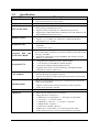
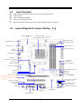
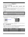
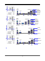
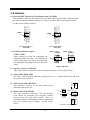
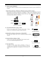
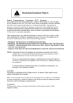
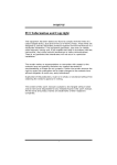
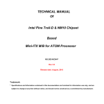
USER'S MANUAL
Of
AMD 690G/690V CHIPSET
&
AMD SB600 Chipset Based
M/B for Socket AM2 64-bit Dual Core
AMD Processor
No. G03-M2A694-F
Rev:2.0
Release date: April. 2008
Trademark:
* Specifications and information contained in this documentation are furnished for information use only, and are
subject to change at any time without notice, and should not be construed as a commitment by manufacturer.
TABLE OF CONTENT
CHAPTER 1
1-1
1-2
1-3
1-4
CHAPTER 2
2-1
2-2
2-3
CONNCTORS, HEADERS & JUMPERS SETTING
CONNECTORS ..................................................................................................................... 9
HEADERS .............................................................................................................................. 12
CHAPTER 4
4-1
4-2
HARDWARE INSTALLATION
INSTALL SOCKET AM2 SUPPORTED AMD PROCESSOR ........................................ 6
INSTALL MEMORY............................................................................................................ 6
EXPANSION CARDS ........................................................................................................... 8
CHAPTER 3
3-1
3-2
INTRODUCTION OF AMD 690G/690V MOTHERBOARD SERIES
FEATURES OF MOTHERBOARD .................................................................................... 1
1-1.1 SPECIAL FEATURES OF MOTHERBOARD.................................................... 2
SPECIFICATION................................................................................................................... 3
ITEM CHECKLIST .............................................................................................................. 4
LAYOUT DIAGRAM & JUMPER SETTING ................................................................... 4
USEFUL HELP
HOW TO UPDATE BIOS..................................................................................................... 14
TROUBLE SHOOTING ....................................................................................................... 14
Environmental Protection Announcement
Do not dispose this electronic device into the trash while discarding. To minimize pollution
and ensure environment protection of mother earth, please recycle.
ii
Chapter 1
Introduction of AMD 690G/690V Motherboard Series
1-1
Features of motherboard
The AMD 690G/690V Series motherboards are based on the latest AMD 690G/690V Chipset
and SB600 chipset which supports the new generation innovative 64-bit AMD Socket AM2
dual core multi-tasking Socket AM2 Athlon64 X2 processors and dual core AMD Phenom™
processors. With an integrated low-latency high-bandwidth DDR2 memory controller and the
highly-scalable Hyper Transport technology-based system bus which is up to 1000 MHZ,
AMD 690G/690V Platform Processor Chipset motherboard series deliver the outstanding system
performance and professional desktop platform solution with the advantages of new
generation 64-bit AMD Socket AM2 Athlon64 X2 processors, AMD Phenom™ processors
and the fully compatibility of the next generation operation system.
The AMD 690G/690V Series motherboards support new generation Socket AM2 processors
with an integrated DDR2 memory controller which provides with 266MHz / 333MHz/
400MHz memory clock frequency for Dual channel DDR2 533 / DDR2 667 / DDR2 800
(Sempron processor of AM2 socket only supports up DDR2 667) DDR2 Module up to 8.0GB.
The whole motherboard series are embedded with SB600 chipset that provides ULTRA ATA
133 connectors and Serial ATA2 with RAID 0, 1 and RAID 10 functions which support up to
two IDE devices and four Serial ATA2 devices to accelerate hard disk drives and guarantee
the data security without failure in advanced computing performance.
The AMD 690V Chipset incorporates ATI Radeon X1200 Graphics with a core frequency of 400
MHz and 2 shader pipeline featured with DirectX 9.0 compliant 2D/3D graphics processor ,
Maximum DAC frequency of 400 MHz Resolution up to 2560x1600 (Under condition), refresh
rate up to 85MHz delivering incredible graphics and blistering performance. Besides, the
AMD 690G Series motherboards integrated ATI Radeon X1250 Graphics support ATI
innovated AVIVO Technology and Multiple Display configurations: CRT+ DVI-D or HDMI on
rear panel and give you the best performance in game experience. AMD™ 690G/690V chipset
provides incredible flexibility and unlimited upgrade potential as it supports all Radeon®
PCI – E graphics cards on a system configured for either single GPU or next generation
multimedia operation. Designed with ATI’s unique architecture to optimize speed and
stability, this solution is perfect for overclocking – without the need of additional cooling
systems.
The 690V /690G series motherboards provide optional 10/100 or 10/100/1000 LAN functions
with Realtek RTL8101E-GR PCI-E 10/100 LAN or RTL8111B-GR PCI-E Gigabit LAN
which supports 10/100Mbps or 10/100/1000 Mbps data transfer rate. And the embedded
optional Azalia 6-channel and 8-channel HD Audio CODEC is fully compatible with Sound
Blaster Pro® standards that offer you with the home cinema quality and satisfying software
compatibility.
The motherboards offer one PCI-Express x16 graphics slot of 4Gbyte/sec data transfer rate at
each relative direction which gets 3.5 times of bandwidth more than AGP 8X and it’s up to a
peak concurrent bandwidth of 8Gbyte/sec at full speed to guarantee the ultimate GPU
computing performance. Two 32-bit PCI slots guarantee the rich connectivity for the I/O of
1
peripherals; the motherboards are designed of tackling the profuse multimedia requirements
nowadays.
Embedded USB controller as well as capability of expanding to 8 of USB2.0 functional ports
delivering 480Mb/s bandwidth and rich connectivity, these motherboards meet the future
USB demands which are also equipped with hardware monitor function on system to monitor
and protect your system and maintain your non-stop business computing.
Some special features---CPU Thermal Throttling/ CPU Vcore 7-shift / CPU Smart Fan this
motherboard are designed for power user to use the over-clocking function in more flexible ways. But
please be caution that the over-clocking maybe cause the fails in system reliabilities. This motherboard
provides the guaranteed performance and meets the demands of the next generation computing. But if
you insist to gain more system performance with variety possibilities of the components you choose,
please be careful and make sure to read the detailed descriptions of these value added product features,
please get them in the coming section.
1-1.1 Special Features of Motherboard
CPU Smart Fan---( The Noise Management System(Only support 4-pin CPU cooler))
It’s never been a good idea to gain the performance of your system by sacrificing its acoustics. CPU Smart
Fan Noise Management System is the answer to control the noise level needed for now-a-day’s high
performance computing system. The system will automatically increase the fan speed when CPU operating
loading is high, after the CPU is in normal operating condition, the system will low down the fan speed for
the silent operating environment. The system can provide the much longer life cycle for both CPU and the
system fans for game use and business requirements.
CPU Vcore 7-Shift--- (Shift to Higher Performance)
The CPU voltage can be adjusted up by 13 steps for the precisely over-clocking of extra demanding
computing performance.
CPU Thermal Throttling Technology---(The CPU Overheat Protection Technology)
To prevent the increasing heat from damage of CPU or accidental shutdown while at high workload, the
CPU Thermal Throttling Technology will force CPU to enter partially idle mode from 87.5% to 12.5%
according to preset CPU operating temperature in BIOS (from 40℃ to 90℃). When the system senses the
CPU operating temperature reaching the preset value, the CPU operating bandwidth will be decreased to
the preset idle percentage to cool down the processor. When at throttling mode the beeper sound can be
optionally selected to indicate it is in working.
2
1-2
Specification
Spec
Description
Design
∗
∗
Chipset
∗
∗
CPU Socket AM2
∗
∗
Memory Socket
Expansion Slot
∗
∗
∗
∗
∗
Integrate IDE and
Serial ATA2 RAID
Integrated VGA
∗
∗
∗
∗
∗
∗
LAN (Option)
∗
∗
Optional Audio
BIOS
Multi I/O
∗
∗
∗
∗
∗
∗
∗
∗
∗
∗
∗
∗
Micro ATX form factor 4 layers PCB
size: 24.4 cm*21.0cm or 24.4*19.3cm
AMD 690G/690V Chipset and AMD SB600 Chipset
Support 64bit AMD AM2 940-Pin package utilizes Flip-Chip Pin Grid
Array package compatible processor
Support for HTT 1GHz dual core AMD Phenom processors
Support HTT 1GHz AMD Athlon 64 X2 processor and Athlon 64, and
HTT 800MHz Sempron Processors
240-pin DDR2 Module socket x 4/2
Support 4 / 2 pcs DDR2 533 / DDR2 667 / DDR2 800 Modules
Expandable to 8.0 / 4.0 GB
PCI-Express x16 slot 1pcs delivers up to 8 GB/s of concurrent
bandwidth.
32-bit PCI slot x 2 pcs
One IDE controllers support PCI Bus Mastering, ATA PIO / DMA and
the ULTRA DMA 33/66/100/133 functions that deliver the data transfer
rate up to 133 MB/s.
Four Serial ATA2 ports provide 300 MB/sec data transfer rate with
RAID 0, 1, 10 functions.
Integrated with ATI Radeon X1200 / X1250 Graphic
a core frequency of 400 MHz and 4 shader pipeline
DirectX 9.0 compliant 2D/3D graphics processor
supported ATI innovated AVIVO Technology and Multiple Display
configurations (only for 690G series)
Integrated Realtek RTL8101E-GR PCI-E 10/100 LAN chip or
RTL8111B-GR PCI-E gigabit LAN chip
Supports Fast Ethernet LAN function provide 10/100 or 10/100/1000
Mb /s data transfer rate
Optional 6-channel Realtek ALC662 or 8-channelALC883 Azalia HD
Audio Codec integrated
Support 8-channel 3D surround & Positioning Audio (optional)
Audio driver and utility included
Award 4MB Flash ROM / Award 4MB SPI Flash ROM
PS/2 keyboard and PS/2 mouse connectors
Floppy disk drive connector x1
1* Parallel port of 25-pin Block / 1 * Serial port of 9-pin Block
1 * VGA port / 1 * TV-OUT header
1 * HDMI port(optional) /1 * DVI port(optional)
1* SPDIF header(optional)
1 * HDTV-OUT header (optional)
USB2.0 port x 4 and headers x 4 (connecting optional cable)
Audio connector (Line-in, Line-out, MIC/optional 8CH Audio)
3
1-3
5
5
5
5
5
Item Checklist
AMD 690G/690V Platform Processor Chipset based motherboard
Cable for IDE
CD for motherboard utilities
Cable for Serial ATA IDE Port
AMD 690G/690V Platform Processor Chipset motherboard User’s Manual
Layout Diagram & Jumper Setting (1)
1-4
Keyboard/USB Power
(JP1)
CPU Socket AM2 CPU FAN
AMD Phenom™ Ready
BIOS BACK Chip
PS2 KB/Mouse Port
I/O Controller Chip
Optional VGA
DDR2 Socket x 4
ATX Power Conn.
Parallel
Connector
Optional DVI
USB Port
ATX 12V Power Connector
RJ45 Over
USB Connector
ATA 133 IDE
Conn.(IDE1)
Floppy Connector
Audio Connector
AMD 690G/690V Chipset
SFAN1
4MBit Flash
ROM BIOS
Clear CMOS (JBAT)
TV-OUT
PCI Express x16
Optional Realtek RTL8101E-GR
/RTL8111B-GR/RTL8111C-GR
LAN chip
Realtek ALC880E
Audio Decode
PCI Slot
Serial-ATAII Connector
(SATA II 1, 2,3,4)
Power LED Connector
Speaker Connector
Audio
Front Panel Connector
USB Port
CDIN
COM1
(USB3, USB4)
USB Power On Jumper (JP2)
Optional SPDIF
4
SFAN2
AMD SB600
Layout Diagram & Jumper Setting (2)
Keyboard/USB Power CPU Socket AM2
(JP1)
AMD Phenom™ Ready
CPU FAN
PS2 KB/Mouse Port
I/O Controller Chip
Optional VGA
DDR2 Socket x 2
ATX Power Conn.
Parallel
Connector
Optional DVI
USB Port
ATX 12V Power Connector
ATA 133 IDE
Conn.(IDE1)
RJ45 Over
USB Connector
SFAN1
Audio Connector
Floppy Connector
AMD 690G/690V Chipset
Audio
CDIN
TV-OUT
Clear CMOS (JBAT)
PCI Express x16
Optional Realtek
RTL8111B-GR/RTL8111C-GR
Gigabit LAN chip
Realtek ALC880E
Audio Decode
PCI Slot
AMD SB600
Chipset
HDTV-OUT
Serial-ATAII Connector
(SATA II 1, 2,3,4)
Front Panel Connector
COM1
USB Port
SFAN2
(USB3, USB4)
USB Power On Jumper (JP2)
5
Speaker Connector
Power LED Connector
Chapter 2
Hardware Installation
2-1 Install Socket AM2 /Socket AM2+ Supported AMD
Processor
This motherboard provides a 940-pin surface mount, Zero Insertion Force (ZIF) socket,
referred to as the mPGA940 socket supports AMD Athlon64 processor in the 940 Pin package
utilizes Flip-Chip Pin Grid Array package technology.
The CPU that comes with the motherboard should have a cooling FAN attached to prevent
overheating. If this is not the case, then purchase a correct cooling FAN before you turn on
your system.
WARNING!
Be sure that there is sufficient air circulation across the processor’s
heatsink and CPU cooling FAN is working correctly, otherwise it may
cause the processor and motherboard overheat and damage, you may install
an auxiliary cooling FAN, if necessary.
To install a CPU, first turn off your system and remove its cover. Locate the ZIF socket and
open it by first pulling the level sideways away from the socket then upward to a 90-degree
angle. Insert the CPU with the correct orientation as shown below. The notched corner
should point toward the end of the level. Because the CPU has a corner pin for two of the
four corners, the CPU will only fit in the orientation as shown.
Socket AM2
Colden Arrow
CPU ZIF mPGAB Socket
When you put the CPU into the ZIF socket, No force require to insert of the CPU, then press
the level to Locate position slightly without any extra force.
2-2
Install Memory
The motherboards provide four / two 240-pin DDRII DUAL INLINE MEMORY MODULES
(DIMM) sites for DDRII memory expansion available from minimum memory size of
128MB to maximum memory size of 8.0GB / 4.0GB DDRII SDRAM.
Valid Memory Configurations of 2-DIMM Design Motherboard
Bank
240-Pin DIMM
PCS
Bank 0, 1 (DIMM1) DDRII400/DDRII533/DDRII667/DDRII800
Bank 2, 3 (DIMM2) DDRII400/DDRII533/DDRII667/DDRII800
Total
System Memory (Max. 4.0GB)
6
X1
X1
2
Total Memory
128MB∼2.0GB
128MB∼2.0GB
128MB∼4.0GB
Valid Memory Configurations of 4-DIMM Design Motherboard
Bank
240-Pin DIMM
PCS
Bank 0, 1 (DIMM1)
Bank 2, 3 (DIMM2)
Bank 4, 5 (DIMM3)
Bank 6,7 (DIMM4)
Total
DDRII400/DDRII533/DDRII667/DDRII800
DDRII400/DDRII533/DDRII667/DDRII800
DDRII400/DDRII533/DDRII667/DDRII800
DDRII400/DDRII533/DDRII667/DDRII800
System Memory (Max. 8.0GB)
Total Memory
X1
X1
X1
X1
4
128MB∼2.0GB
128MB∼2.0GB
128MB∼2.0GB
128MB∼2.0GB
128MB∼8.0GB
Recommend DIMM Module Combination
1.
2.
3.
One DIMM Module ----Plug in DIMM1
Two DIMM Modules---Plug in DIMM1 and DIMM2 or DIMM3 and DIMM4 for Dual
channel function of 4-DIMM Design motherboard and Plug in DIMM1 and DIMM2 for
Dual channel function of 2-DIMM Design motherboard.
Four DIMM Modules---Plug in DIMM1/DIMM2/DIMM3/DIMM4.
For Dual channel Limited!
1.
2.
Dual channel function only supports when 2 DIMM Modules plug in either both DIMM1 &
DIMM2 or DIMM3 &DIMM4, or four DIMM Modules plug in DIMM1~DIMM4 of 4-DIMM
motherboard and 2 DIMM Modules plug in DIMM1 & DIMM2 of 2-DIMM Motherboard.
DIMM1 & DIMM2, or DIMM3 & DIMM4 of 4-DIMM motherboard, and DIMM1 &
DIMM2 of 2-DIMM motherboard must be the same type, the same size, and the same
frequency for dual channel function.
Generally, installing DDR SDRAM modules to your motherboard is very easy, you can refer
to figure 2-4 to see what a 240-Pin DDR2 400 / 533 / 667 / 800 SDRAM module looks like.
Figure 2-4
DIMM1 & DIMM2: Dual Channel 1
DIMM3 & DIMM4: Dual Channel 2
NOTE!
When you install DIMM module fully into the DIMM socket the eject
tab should be locked into the DIMM module very firmly and fit into its
indention on both sides
7
2-3 Expansion Cards
The motherboards offer one PCI-Express x16 graphics slot of 4Gbyte/sec data transfer rate at
each relative direction which gets 3.5 times of bandwidth more than AGP 8X and it’s up to a
peak concurrent bandwidth of 8Gbyte/sec at full speed to guarantee the ultimate GPU
computing performance. Two32-bit PCI slots guarantee the rich connectivity for the I/O of
peripherals; the motherboards are designed of tackling the profuse multimedia requirements
nowadays.
PE1 / PCI-E x16 Slot
32-bit PCI Slot
8
Chapter 3
Connectors, Headers & Jumpers Setting
3-1
Connectors
(1)
Power Connector (24-pinblock) :
ROW1 ROW2
ATXPWR1
PIN
ROW1
ROW2
ROW1 ROW2
ATX Power Supply connector: This is a
1
3.3V
3.3V
2
3.3V
-12V
new defined 24-pins connector that
3
GND
GND
usually comes with ATX case. The ATX
4
5V
Soft Power On
Power Supply allows using soft power on
5
GND
GND
6
5V
GND
momentary switch that connect from the
7
GND
GND
front panel switch to 2-pins Power On
8
Power OK
-5V
9
+5V (for Soft Logic)
+5V
jumper pole on the motherboard. When
10
+12V
+5V
the power switch on the back of the ATX
11
+12V
+5V
power supply turned on, the full power
12
+3V
GND
will not come into the system board until
the front panel switch is momentarily
Pin 1
Pin 1
pressed. Press this switch again will turn
24-Pin
off the power to the system board.
20-Pin
** We recommend that you use an ATX 12V
Specification 2.0-compliant power supply unit (PSU) with a minimum of 350W power rating. This
type has 24-pin and 4-pin power plugs.
** If you intend to use a PSU with 20-pin and 4-pin power plugs, make sure that the 20-pin power plug
can provide at least 15A on +12V and the power supply unit has a minimum power rating of 350W.
The system may become unstable or may not boot up if the power is inadequate.
(2)
(3)
(4)
(5)
ATX 12V Power Connector (8-pin block) : ATX12V1
This is a new defined 8-pins connector that usually comes with ATX Power Supply. The ATX Power
Supply which fully supports AM2 processor must including this
connector for support extra 12V voltage to maintain system power
consumption. Without this connector might cause system unstable
because the power supply can not provide sufficient current for system.
PS/2 Mouse & PS/2 Keyboard Connector: KB1
The connectors are for PS/2 keyboard and PS/2 Mouse
.
USB Port connector: CN3
The connectors are 4-pin connectors that connect USB devices to the system board.
LAN Port connector: UL1
This connector is standard RJ45 connector for Network
10M/100M or 10M/100Mb/1000Mb s data transfer rate
The
USBLAN1
support
optional
(6) Audio Line-In, Lin-Out, MIC, Surrback, Surround, CEN/LEF Connector: SURROUND1 / CN1
This Connector are 6 phone Jack for LINE-OUT, LINE-IN, MIC, Surrback, Surround, CEN/LEF
Line-in : (BLUE)
Audio input to sound chip
Line-out : (GREEN)
Audio output to speaker
MIC : (PINK)
Microphone Connector
Surrback : (ORANGE)
Audio output to speaker-Rear speaker out
CEN/LEF : (BLACKNESS) Audio output to speaker-Center/Subwoofer speaker out
Surround: (GRAY)
Audio output to speaker-Side speaker out
9
PS/2
Mouse
Gigabit LAN
Line-IN
Surrback
Line-OUT
CEN/LFE
VGA
Surround
MIC-IN
PS/2
Keyboard
DVI
PS/2
Mouse
USB1
UL2
Gigabit LAN
Line-IN
Surrback
Line-OUT
CEN/LFE
HDMI
PS/2
Keyboard
VGA
PS/2
Mouse
Surround
MIC-IN
USB1
UL2
10/100 LAN
Line-IN
Line-OUT
VGA
MIC-IN
PS/2
Keyboard
USB1
PS/2
Mouse
UL2
10/100 LAN
VGA
Line-IN
Line-OUT
MIC-IN
PS/2
Keyboard
DVI
10
USB1
UL2
(7) Floppy drive Connector (34-pin block): FDD1
This connector supports the provided floppy drive ribbon cable.
After connecting the single plug end to motherboard,
connect the two plugs at other end to the floppy drives.
FDD
Pin 1
(8) Primary IDE Connector (40-pin block): IDE1
Floppy Drive Connector
This connector connects to the next set of Master and Slave
IDE1
hard disks. Follow the same procedure described for the
primary IDE connector. You may also configure two hard disks to
be both Masters using one ribbon cable on the primary IDE
connector and another ribbon cable on the secondary IDE
connector.
Pin 1
• Two hard disks can be connected to each connector. The first
Primary IDE Connector
HDD is referred to as the “Master” and the second HDD is referred
to as the “Slave”.
• For performance issues, we strongly suggest you don’t install a CD-ROM or DVD-ROM
drive on the same IDE channel as a hard disk. Otherwise, the system performance on this
channel may drop.
SATA4
(9) Serial-ATA Port connector:
SATA1 / SATA2 / SATA3/ SATA4
These connectors support the provided Serial
ATA and Serial ATA2 IDE hard disk cable to
connecting the motherboard and serial ATA
hard disk.
SATA3
SATA2
SATA1
Serial-ATA1 & 2 Compatible Connectors
(10)
D-Sub 15-pin Connector: VGA
VGA is the 15-pin D-Subminiature female connector; it is for the display devices, such
as the CRT monitor, LCD monitor and so on.
(11)
DVI: Digital Visual Interface (Optional)
This interface standard designed to maximize the visual quality of digital display
devices such as flat panel LCD computer displays and digital projectors.
(12)
HDMI: High-Definition Multimedia Interface (Optional)
This point-to-point interface is for audio and video signals designed as a single-cable
solution for home theater and consumer electronics equipment.
11
3-2 Headers
AUD_RET_L
AUD_GND
AUD_VCC
AUD_RET_R
AUDIO
10
2
10
Pin 1
9
AUD_MIC
AUD_MIC_BIAS
AUD_FPOUT_R
HP_ON
AUD_FPOUT_L
MIC2-L
MIC2-R
LINEOUUT2-R
SENSE-FB
LINEOUT2-L
9
Line-Out, MIC Headers
Line-Out, MIC Headers
+DATA
GND
OC
VCC
-DATA
VCC
USB4
-DATA
Pin 1
Pin 1
+DATA
GND
USB3 / USB4
These headers are used for connecting the
additional USB port plug. By attaching an
option USB cable, your can be provided with
two additional USB plugs affixed to the back
panel.
+DATA
GND
OC
USB3
+DATA
GND
(2) USB Port Headers (9-pin) :
VCC
ALC662
-DATA
ALC883
VCC
2
Pin 1
-DATA
AUDIO
AUD_GND
AUD_GND
AUD_JD 9
AUD_GND
(1) Line-Out/MIC Header for Front Panel (9-pin): AUDIO1
These headers connect to Front Panel Line-out, MIC connector with cable. Without install
the cable, this header default setting is 5-6 short, 9-10 short. When you install the cable
you have take off these jumpers.
USB Port Headers
(3) Speaker connector: SPEAK1
This 4-pin connector connects to the case-mounted speaker. See the figure below.
(4) Power LED: PWR LED1
The Power LED is light on while the system power is on. Connect the Power LED from
the system case to this pin.
Pin 1
JW FP
PWRBTN
GND
SPEAK
VCC5
HDDLE
GND
RSTSW
NC
HDLED
RESET
GND
VCC5
Pin 1
SPKR
NC
Pin 1
System Case Connections
12
PWRBTN
PWRLED
(6) Reset switch lead: RESET
This 2-pin connector connects to the case-mounted
reset switch for rebooting your computer without
having to turn off your power switch. This is a
preferred method of rebooting in order to prolong the
lift of the system’s power supply. See the figure
below.
PWRLED
VCC5
PWR LED
(5) IDE Activity LED: HD LED
This connector connects to the hard disk activity
indicator light on the case.
(7) Power switch: PWR BTN
This 2-pin connector connects to the case-mounted power switch to power ON/OFF the
system.
CPUFAN OUT
CPUFAN IN
GND
+12V
(8) FAN Power Headers: SYSFAN1, SYSFAN2 (3-pin), CPUFAN (4-pin)
These connectors support cooling fans of 350mA (4.2 Watts) or less, depending on the fan
manufacturer, the wire and plug may be different. The red wire should be positive,
while the black should be ground. Connect the fan’s plug to the board taking into
consideration the polarity of connector.
CPUFAN
4
1
SYSFAN2
SYSFAN1
3
1
3
1
FAN Power Headers
(9) CD Audio-In Headers (4-pin) : CDIN
CDIN are the connectors for CD-Audio Input signal.
connect it to CD-ROM CD-Audio output connector.
Please
CDIN
4
1
CD Audio-In Headers
(10) Parallel Port Header (25-pin male): PARALLEL1
The On-board Parallel Port can be disabled through the BIOS
SETUP.
Pin 1
PARALLEL
(11) Serial COM Port Header: COM1
COM1 is the 9-pin block pin-header. The On-board serial
port can be disabled through BIOS SETUP.
Pin1
Serial COM Port 9-pin Block
(12) TV-OUT Header
TV-OUT is the 9-pin block pin-header. TV-out is
commonly used to label the connector of equipment offering
an analog video signal that is acceptable for a television AV
input.
13
Pin1
TV-OUT Conn. 9-pin Block
Chapter 4
USEFUL HELP
4-1 HOW TO UPDATE BIOS
Before updating the BIOS, users have to “Disable” the “Flash Part Write Protect” selection in
“Miscellaneous Control” of BIOS SETUP. Otherwise the system the will not allow you to upgrade
BIOS by Award Flash Utility.
STEP 1. Prepare a boot disc. (you may make one by click START click RUN type SYS A:click OK)
STEP 2. Copy utility program to your boot disc. You may copy from DRIVER CD
X:\FLASH\AWDFLASH.EXE or download from our web site.
STEP 3. Download and make a copy of the latest BIOS for AMD690X PPC motherboard series
from the web site to your boot disc.
STEP 4. Insert your boot disc into A:,
start the computer, type “Awdflash A:\ AMD690X.BIN /SN/PY/CC/R”
AMD690X xxx.BIN is the file name of latest BIOS it can be AMD690Xa.BIN or
AMD690Xb.BIN
SN
means
don’t save existing BIOS data
PY
means
renew existing BIOS data
CC
means
clear existing CMOS data
R
means
restart computer
STEP 5. Push ENTER to update and flash the BIOS, then the system will restart automatically.
4-2 Trouble Shooting
Problem
Solution
No power to the system to the all power light
don’t illuminate, fan inside power supply doesn’t
turn on.
System inoperative. Keyboard lights are on ,
power indicator lights are lit, and hard drive is
spinning.
System doesn’t boot from hard disk drive, can be
booted from optical drive.
1. Make sure power cable is security plugged in.
2. Replace cable. 3. Contact technical support.
System only boots from optical drive .Hard disk
can be read and applications can be used but
booting from hard disk is impossible.
Screen message says “Invalid Configuration” or
“CMOS Failure”
Can not boot system after installing second hard
drive.
1. Back up date and applications files. 2.
Reformat the hard drive. Reinstall applications
and date using backup disks.
Review system ‘s equipment .Make sure correct
information on is in setup.
1. Set master /slave jumpers correctly. 2. Run
SETUP program and select correct drive types.
Call the drive manufacture for compatibility with
other drives.
Using ever pressure on both ends of the DIMM ,
press down firmly until the module snaps into
places.
1. Check cable running from disk to disk
controller board. .Make sure both ends are
securely plugged in, check the drive type in the
standard CMOS setup. 2. Backing up the hard
drive is extremely important .All hard disks are
capable of breaking down at any time.
14