1
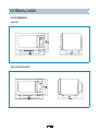
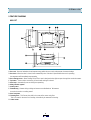
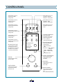
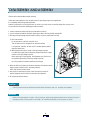
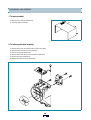
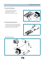
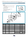
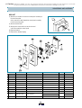
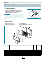
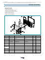
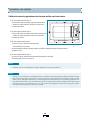
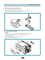
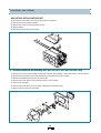
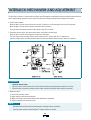
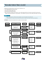
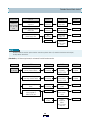
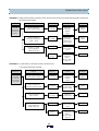
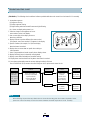
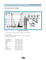
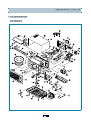
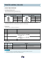
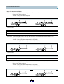
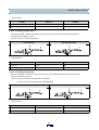
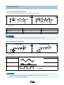
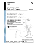
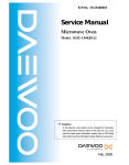
S/M No. : C972T0S003
Service Manual
Microwave Oven
Model: KOC-972T0S
KOC-972T2S
KOC-982T1S
KOC-982T2S
KOC-983T1S
KOC-983T2S
KOC-984T1S
KOC-984T2S
KOC-985T1S
KOC-985T2S
✔ Caution
: In this Manual, some parts can be changed for improving, their
performance without notice in the parts list. So, if you need the
latest parts information,please refer to PPL(Parts Price List) in
Service Information Center (http://svc.dwe.co.kr).
DAEWOO ELECTRONICS CO., LTD.
PRECAUTIONS TO BE OBSERVED BEFORE AND
DURING SERVICING TO AVOID POSSIBLE
EXPOSURE TO EXCESSIVE MICROWAVE ENERGY
(a) Do not operate or allow the oven to be operated w ith the door open.
(b) M ake the following safety checks on all ovens to be serviced before activating the m agnetron or other m icrowave
source, and m ake repairs as necessary: (1) Interlock operation, (2) Proper door closing, (3) Seal and sealing
surfaces (arcing, wear, and other dam age), (4) Dam age to or loosening of hinges and latches, (5) Evidence of
dropping or abuse.
(c) Before turning on power to the m icrow ave oven for any service test or inspection within the m icrowave
generating com partm ents, check the m agnetron, wave guide or transm ission line, and cavity for proper
alignm ent, integrity, and connections.
(d) Any defective or m isadjusted com ponents in the interlock, m onitor, door seal, and m icrowave generation and
transm ission system s shall be repaired, replaced, or adjusted by procedures described in this m anual before the
oven is released to the owner.
(e) A m icrowave leakage check to verify com pliance with the Federal perform ance standard should be perform ed on
each oven prior to release to the owner.
SAFETY AND PRECAUTIONS ........................................................................................................... 2
SPECIFICATIONS ............................................................................................................................... 3
EXTERNAL VIEW................................................................................................................................ 4
1. OUTER DIMENSION..................................................................................................................... 4
2. FEATURE DIAGRAM................................................................................................................... 5
INSTALLATION ................................................................................................................................... 7
EARTHING INSTRUCTIONS............................................................................................................... 7
CONTROL PANEL .............................................................................................................................. 8
DISASSEMBLY AND ASSEMBLY...................................................................................................... 9
INTERLOCK MECHANISM AND ADJUSTMENT............................................................................... 23
TROUBLE SHOOTING GUIDE ........................................................................................................... 24
MEASUREMENT AND TEST .............................................................................................................. 30
1. MEASUREMENT OF THE MICROWAVE POWER OUTPUT ...................................................... 30
2. ELECTRICAL CONTINUITY CHECK OF INTERLOCK SWITCH................................................. 31
3. MICROWAVE RADIATION TEST ................................................................................................. 32
4. COMPONENT TEST PROCEDURE ............................................................................................. 33
WIRING DIAGRAM.............................................................................................................................. 34
SCHEMATIC DIAGRAM...................................................................................................................... 35
EXPLODED VIEWS AND PARTS LIST .............................................................................................. 38
PRINTED WIRING BOARD ................................................................................................................. 44
P.C.B. CIRCUIT DIAGRAM ................................................................................................................. 49
SAFETY AND PRECAUTIONS
1. FOR SAFE OPERATION
Damage that allows the microwave energy (that cooks or heats the food) to escape will result in poor cooking and may
cause serious bodily injury to the operator.
IF ANY OF THE FOLLOWING CONDITIONS EXIST, OPERATOR MUST NOT USE THE APPLIANCE.
(Only a trained service personnel should make repairs.)
(1) A broken door hinge.
(2) A broken door viewing screen.
(3) A broken front panel, oven cavity.
(4) A loosened door lock.
(5) A broken door lock.
The door gasket plate and oven cavity surface should be kept clean.
No grease, soil or spatter should be allowed to build up on these surfaces or inside the oven.
DO NOT ATTEMPT TO OPERATE THIS APPLIANCE WITH THE DOOR OPEN.
The microwave oven has concealed switches to make sure the power is turned off when the door is opened.
Do not attempt to defeat them.
DO NOT ATTEMPT TO SERVICE THIS APPLIANCE UNTIL YOU HAVE READ THIS SERVICE MANUAL.
2. FOR SAFE SERVICE PROCEDURES
1. If the oven is operative prior to servicing, a microwave emission check should be performed prior to servicing the oven.
2. If any certified oven unit is found to servicing, a microwave emission check should be performed prior to servicing the oven.
(1) inform the manufacturer, importer or assembler,
(2) repair the unit at no cost to the owner,
(3) attempt to ascertain the cause of the excessive leakage,
(4) tell the owner of the unit not to use the unit until the oven has been brought into compliance.
3. If the oven operates with the door open, the service person should tell the user not to operate the oven and contact
the manufacturer immediately.
IMPORTANT
The w ire in this m ains lead coloured in accordance with the follow ing code.
G reen-and-yellow
B lue
B row n
: E arth
: N eutral
: Live
A s the colours of the w ires in the m ains lead of this appliance m ay not correspond w ith the coloured m arkings
identifying the term inals in your plug, proceed as follow s.
The w ire which is coloured green-and-yellow m ust be connected to the term inal in the plug w hich is m arked w ith the
letter 'E ' , earth sym bol or coloured green-and-yellow.
The wire which is coloured blue must be connected to the terminal which is marked with the letter 'N' or coloured black.
The wire which is coloured brown must be connected to the term inal w hich is marked with the letter 'L' or coloured red.
NOTE
This oven is designed for counter-top use only.
SPECIFICATIONS
M ODEL
KO C -972T 0S
K O C-972T 2S
P O W E R S U P P LY
230V ~50H z
230V~50H z
M IC RO W AVE
1450W
1450W
G R ILL
1200W
1200W
C O N VE C T IO N
1550W
1550W
PROGRAM COOK
1850W
1850W
C O M B IN AT IO N
2600W (S im ultaneous)
1550W (S equential)
M IC R O W AV E EN E R G Y O U TP U T
950W (IE C 705)
950W (IE C 705)
M IC R O W AV E FR E Q U EN C Y
2450M Hz
2450M H z
O UT S ID E D IM EN S IO NS (W X H X D)
526 x 345 x 413 m m (20.7 x 13.6 x 16.1 in.)
C AV IT Y D IM E N S IO N S (W X H X D )
335 x 255 x 339 m m (13.2 x 10.0 x 13.3 in.)
N ET W E IG H T
AP P R O X . 20 Kg (44.2 lbs.)
T IM E R
60 m inutes
F UN C T IO N S E LE C T IO N S
M IC R O W AV E/G R ILL/C O N VE C T IO N /C O M B I
P O W E R S E LE CT IO N S
10 LE VE LS
C AV IT Y V O LU M E
1.0 C u.F t.
M ODEL
KO C -982T /983T /984T/985T 1S
K O C-982T /983T /984T /985T 2S
P O W E R S U P P LY
230V ~50H z
230V~50H z
M IC RO W AVE
1450W
1450W
G R ILL
1200W
1200W
C O N VE C T IO N
1550W
1550W
PROGRAM COOK
1850W
1850W
C O M B IN AT IO N
2600W (S im ultaneous)
1550W (S equential)
M IC R O W AV E EN E R G Y O U TP U T
1000W (IE C 705)
1000W (IE C705)
M IC R O W AV E FR E Q U EN C Y
2450M Hz
2450M H z
O UT S ID E D IM EN S IO NS (W X H X D)
526 x 345 x 496 m m (20.7 x 13.6 x 19.5 in.)
C AV IT Y D IM E N S IO N S (W X H X D )
335 x 250 x 339 m m (13.2 x 9.8 x 13.3 in.)
N ET W E IG H T
AP P R O X . 21 Kg (46.3 lbs.)
T IM E R
60 m inutes
F UN C T IO N S E LE C T IO N S
M IC R O W AV E/G R ILL/C O N VE C T IO N /C O M B I
P O W E R S E LE CT IO N S
10 LE VE LS
C AV IT Y V O LU M E
1.0 C u.F t.
P O W E R C O N SU M PT IO N
P O W E R C O N SU M PT IO N
SPECIFICATIONS ARE SUBJECT TO CHANGE WITHOUT NOTICE.
EXTERNAL VIEW
1. OUTER DIMENSION
KOC-972T
KOC-982T/983T/984T/985T
EXTERNAL VIEW
2. FEATURE DIAGRAM
KOC-972T
1. Door seal - Door seal maintains the microwave energy within the oven cavity and prevents microwave leakage.
2. Door hook - When the door is closed, it will automatically shut. If the door is opened while the oven is operating,
the magnetron will immediately stop operating.
3. Door viewing screen - Allows viewing of food. The screen is designed so that light can pass through, but not the microwave.
4. Top heater - Turns on when convection, grill and combi cooking is selected.
5. Oven lamp - Automatically turns on during oven operating.
6. Safety interlock system
7. Control panel
8. Turntable tray - Rotates during cooking and ensure even distribution of Microwaves.
It can also be used as a cooking utensil.
9. Oven front plate
10. Rotating base - This fits over the shaft in the center of the ovens cavity floor.
This is to remain in the oven for all cooking. It should only be removed for cleaning.
11. Under heater
EXTERNAL VIEW
KOC-982T/983T/984T/985T
1. Door seal - Door seal maintains the microwave energy within the oven cavity and prevents microwave leakage.
2. Door hook - When the door is closed, it will automatically shut. If the door is opened while the oven is operating,
the magnetron will immediately stop operating.
3. Door viewing screen - Allows viewing of food. The screen is designed so that light can pass through, but not the microwave.
4. Top heater - Turns on when convection, grill and combi cooking is selected.
5. Oven lamp - Automatically turns on during oven operating.
6. Safety interlock system
7. Control panel
8. Turntable tray - Rotates during cooking and ensure even distribution of Microwaves.
It can also be used as a cooking utensil.
9. Oven front plate
10. Rotating base - This fits over the shaft in the center of the ovens cavity floor.
This is to remain in the oven for all cooking. It should only be removed for cleaning.
11. Under heater
12. Metal rack
13. Convection outlet & Fan
6
INSTALLATION
1. Steady, flat location
This microwave oven should be set on a steady, flat surface.
This microwave oven is designed for counter top use only.
2. Leave space behind and side
All air vents should be kept a clearance. If all vents are covered during operation, the oven may overheat and,
eventually, cause failure.
3. Away from radio and TV sets
Poor television reception and radio interference m ay result if the oven is located close to a TV, radio, antenna or feeder and so on.
Position the oven as far from them as possible.
4. Away from heating appliances and water taps
Keep the oven away from hot air, steam or splash when choosing a place to position it,
or the insulation might be adversely affected and breakdowns occur.
5. Power supply
Check your local power source. This microwave oven requires a current of approximately 13amperes, 230 Volts, 50 Hz.
Power supply cord is about 1.2 meters long.
The voltage used must be the same as specified on this oven. Using a higher voltage may result in a fire or other accident
causing oven damage. Using low voltage will cause slow cooking. We are not responsible for damage resulting from use of
this oven with a voltage of ampere fuse other than those specified.
This appliance is supplied with cable of special type, which, if damaged, must be repaired with cable of same type.
Such a cable can be purchased from DAEWOO and must be installed by a Qualified Person.
6. Examine the oven after unpacking for any damage such as:
A misaligned door, broken door or a dent in cavity.
If any of the above are visible, DO NOT INSTALL, and notify dealer immediately.
7. Do not operate the oven if it is colder than room temperature.
(This may occur during delivery in cold weather.) Allow the oven to become room temperature before operating.
EARTHING INSTRUCTIONS
This appliance must be earthed. In the event of an electrical short circuit, earthing reduces the risk of the electric shock by providing an escape wire for the electric current. This appliance is equipped with
a cord having a earthing wire with a earthing plug. The plug must be plugged into an outlet that is properly installed and earthed.
WARNING
Im proper use of the earthing plug can result in a risk of electric shock.
C onsult a qualified electrician or servicem an if the earthing instructions are not com pletely understood, or if doubt
exists as to w hether the appliance is properly earthed, and either:
If it is necessary to use an extension cord, use only a 3-w ire extension cord that has a 3-blade earthing plug,
and a 3-slot receptacle that w ill accept the plug on the appliance.
The m arked rating of the extension cord should be equal to or greater than the electrical rating of the appliance,
or D o not use an extension cord.
CONTROL PANEL
When blinking, the oven is
operating in "COMBI"
cooking mode.
When blinking, the oven is
operating in "WEIGHT
DEFROST" cooking mode.
When blinking, the oven is
operating in "GRILL"
cooking mode.
When blinking, the oven is
operating in "TIME
DEFROST" cooking mode.
When blinking, the oven is
operating in "MICROWAVE"
cooking mode.
When blinking, the oven is
operating in "PROGRAM COOK"
cooking mode.
DEFROST
MW
GRILL
PROGRAM PIE
COOK
COMBI
TEMP
COOK
DEFROST
M/W
WEIGHT - TIME
KG
PIE
When blinking, the oven is
operating in "PIE"
cooking mode.
GRILL
COMBI
TEMP
When blinking, the oven is
operating in "CONVECTION"
cooking mode.
Used to select the variable
microwave power level. If
this button(pad) is pressed for
more than 1.3 sec, number
is scrolled up automatically.
Temperature Button(pad)Used to set desired
temperature. If this button
is pressed for more than
1.3 sec, number is
scrolled up automatically.
Function Buttons(pads)Used to select desired
cooking function.
M/W : MICROWAVE
GRILL
DEFROST : TIME or WEIGHT
DEFROST
TEMP : CONVECTION
COMBI : COMBINATION
PIE
PROGRAM COOK
PROGRAM COOK
Microwave Power Level-
When blinking, the oven is
operating in weght input
mode.
1.ROAST BEEF
2.ROAST PORK
3.ROAST CHICKEN
4.FISH FILLET
5.VEGETABLE
SPEEDY COOK
+
Speedy Cook Button(pad)Used to program quickly
cooking time in 30 sec
increments.
Dial KnobUsed to input the cooking
time and weight.
_
Start ButtonSTOP/CLEAR
START
Used to start the selected
cooking cycle.
(KOC-972T)
Stop/Clear ButtonUsed to pause and clear
all information manually
put into the oven.
(START/CLOCK)
Start/Clock ButtonUsed to start the selected
cooking cycle and to set
time.
(KOC-982T/983T/984T/985T)
DISASSEMBLY AND ASSEMBLY
Cautions to be observed when trouble shooting.
Unlike many other appliances, the microwave oven is high-voltage, high-current equipment.
It is completely safety during normal operation.
However, carelessness in servicing the oven can result in an electric shock or possible danger from a short circuit.
You are asked to observe the following precautions carefully.
1. Always remove the power plug from the outlet before servicing.
2. Use an insulated screwdriver and ware rubber gloves when servicing the high voltage side.
3. Discharge the high voltage capacitor before touching any oven components or wiring.
(1) Check the earthed.
Do not operate on a two-wire extension cord.
The microwave oven is designed to be used with earthed.
It is imperative, therefore, to make sure it is earthed properly before
beginning repair work.
(2) Warning about the electric charge in the high voltage capacitor.
For about 30 seconds after the operation stopped and electric charge
remains in the high voltage capacitor.
When replacing or checking parts, short between oven chassis and
the negative high terminal of the high voltage capacitor,
by using a properly insulated screwdriver to discharge.
4. When the 15A fuse is blown out due to the operation of the monitor switch;
replace primary interlock switch, secondary interlock
switch and interlock monitor switch.
5. After repair or replacement of parts, make sure that the screws are
properly tightened, and all electrical connections are tightened.
6. Do not operate without cabinet.
CAUTION
S ervice personnel should rem ove their w atches w henever w orking close to or replacing the m agnetron.
WARNING
W hen servicing the appliance, need a care of touching or replacing high potential parts because of electrical shock or
exposing m icrow ave. These parts are as follow s - HV Transform er, M agnetron, H V C apacitor, H V D iode.
DISASSEMBLY AND ASSEMBLY
1. To remove cabinet
(1) Remove four screws on cabinet back.
(2) Push the cabinet backward.
2. To remove guide wind assembly
(1) Remove two screws for earthing and for fixing to rear-plate.
(2) Remove the noise filter from the guide wind.
(3) Pull the fan from the motor shaft.
(4) Remove two screws which secure the motor shaded pole.
(5) Remove the motor shaded pole.
(6) Reverse the above steps for reassembly.
DISASSEMBLY AND ASSEMBLY
3. To remove H.V.transformer
(1) Remove four screws which secure
the H.V.transformer to the base plate.
(2) Remove the H.V.transformer.
(3) Reverse the above steps for reassembly.
4. To remove high voltage capacitor
(1) Remove a screw which secure the grounding ring
terminal of the H.V. diode and the capacitor holder.
(2) Remove the H.V. diode from the capacitor holder.
(3) Reverse the above steps for reassembly.
High voltage circuit wiring
DISASSEMBLY AND ASSEMBLY
5. To remove magnetron
(1) Remove three screws which secure the magnetron.
(2) Remove the magnetron.
(3) Reverse the above steps for reassembly.
CAUTION
N ever install the m agnetron w ithout the m etallic gasket plate which is packed w ith each m agnetron to prevent
m icrow ave leakage. W henever repair w ork is carried out on m agnetron, check the m icrow ave leakage. It shall not
exceed 4m W /cm 2 for a fully assem bled oven with door norm ally closed.
✔ Caution: In this Service Manual, some parts can be changed for improving, their performance without notice in the parts list. So, if you need the
latest parts information, please refer to PPL(Parts Price List) in Service information Center(http://svc.dwe.co.kr)
DISASSEMBLY AND ASSEMBLY
6. To remove control panel assembly
KOC-972T, KOC-982T
(1) Remove a screw which secure the control panel assembly to
the oven front plate.
At the same time, draw forward the control panel assembly
from the oven front plate.
(2) Remove nine screws which secure the main and
sub PCB assembly to control panel.
(3) Remove buttons and dial knob.
REF NO.
PART CO DE
PART NAM E
DESCRIP TION
QTY
B 01
3516715120
C O NT R O L-PA N E L
A BS X R -401
1
B 02
3515501210
W IND O W D IS P LAY
P M M A IF-850
1
B 03
3516905100
B U TT O N F UN C T IO N -A
A BS X R -401
1
B 04
3516906200
B U TT O N F UN C T IO N -B
A BS X R -401
1
B 05
3513404600
K N O B V O LU M E
A BS X R -401
1
B 06
3516906300
B U TT O N F UN C T IO N -C
A BS X R -401
2
B 07
P K B PM S P 500
P C B S U B AS
K O C -972T, K O C-982T
1
B 08
7621301011
S C RE W TA PP IN G
T 2S PA N 3x10 P W M F Z N
6
B 09
P K M P M S Q 300
P C B M A IN A S
K O C -972T0S
1
P K M P M S Q 300
P C B M A IN A S
K O C -972T2S
1
P K M P M S Q 350
P C B M A IN A S
K O C -982T1S
1
P K M P M S Q 350
P C B M A IN A S
K O C -982T2S
1
7621301011
S C RE W TA PP IN G
T 2S PA N 3x10 P W M F Z N
3
B 10
REMARK
✔ Caution: In this Service Manual, some parts can be changed for improving, their performance without notice in the parts list. So, if you need the
latest parts information, please refer to PPL(Parts Price List) in Service information Center(http://svc.dwe.co.kr)
DISASSEMBLY AND ASSEMBLY
KOC-983T
(1) Remove a screw which secure the control panel assembly to
the oven front plate.
At the same time, draw forward the control panel assembly
from the oven front plate.
(2) Remove ten screws which secure the main and
sub PCB assembly to control panel.
(3) Remove buttons.
(4) Remove the knob volume.
REF NO.
PART CODE
PART NAME
DESCRIPTION
QTY
B01
3516719220
CONTROL-PANEL
ABS XR-401
1
B02
3511603120
DECORATOR C-PANEL
PET T0.2
1
B03
3513405200
KNOB VOLUME
ABS XR-401
1
B04
3516906300
BUTTON FUNCTION
ABS XR-401
1
B05
PKBPMSYB00
PCB SUB AS
KOC-984T
1
B06
7621301011
SCREW TAPPING
T2S PAN 3X10 PW MFZN
6
B07
PKMPMSYB00
PCB MAIN AS
KOC-983T1S
KOC-983T2S
1
B08
7122401211
SCREW TAPPING
T2S TRS 4X12 MFZN
4
14
REMARK
✔ Caution: In this Service Manual, some parts can be changed for improving, their performance without notice in the parts list. So, if you need the
latest parts information, please refer to PPL(Parts Price List) in Service information Center(http://svc.dwe.co.kr)
DISASSEMBLY AND ASSEMBLY
KOC-984T
(1) Remove a screw which secure the control panel assembly to
the oven front plate.
At the same time, draw forward the control panel assembly
from the oven front plate.
(2) Remove the dial knob.
(3) Remove ten screws which secure the main and
sub PCB assembly to control panel.
(4) Remove buttons.
(5) Remove the decorator panel.
REF NO.
PART CO DE
PART NAM E
DESCRIP TION
QTY
REMARK
B 01
3516719200
C O NT R O L-PA N E L
A BS X R -401
1
B 02
3511602900
D E CO R ATO R C/P *T
S TS 304 T0.6 H /L
1
B 03
3511603000
D E CO R ATO R C/P *U
S TS 304 T0.6 H /L
1
B 04
3511603110
D E CO R ATO R C-PA N E L
P M M A IF-850
1
SM O G
B 05
3511602800
D E CO R ATO R RIN G
A BS X R -401
1
CO AT IN G
B 06
3513404620
K N O B V O LU M E
A BS X R -401
1
CO AT IN G
B 07
3516905120
B U TT O N F UN C T IO N
A BS X R -401
1
CO AT IN G
B 08
3516907200
B U TT O N F UN C T IO N
A BS X R -401
1
CO AT IN G
B 09
3516906320
B U TT O N F UN C T IO N
A BS X R -401
2
CO AT IN G
B 10
P K B PM S Y B00
P C B S U B AS
K O C -984T
1
B 11
7621301011
S C RE W TA PP IN G
T 2S PA N 3x10 P W M F Z N
6
B 12
P K M P M S YB 00
P C B M A IN A S
B 13
7122401211
S C RE W TA PP IN G
K O C -984T1S
K O C -984T2S
T 2S T R S 4x12 M F Z N
1
4
✔ Caution: In this Service Manual, some parts can be changed for improving, their performance without notice in the parts list. So, if you need the
latest parts information, please refer to PPL(Parts Price List) in Service information Center(http://svc.dwe.co.kr)
DISASSEMBLY AND ASSEMBLY
KOC-985T
(1) Remove a screw which secure the control panel assembly to
the oven front plate.
At the same time, draw forward the control panel assembly
from the oven front plate.
(2) Remove the dial knob.
(3) Remove ten screws which secure the main and
sub PCB assembly to control panel.
(4) Remove buttons.
(5) Remove the window display.
REF NO.
PART CO DE
PART NAM E
DESCRIP TION
QTY
REMARK
B 01
3516719210
C O NT R O L-PA N E L
A BS X R -401
1
B 02
3511603100
D E CO R ATO R C-PA N E L
S TS 304 T0.6 H /L
1
B 03
3515501400
W IND O W D IS P LAY
P M M A IF-850
1
SM O G
B 04
3513404620
K N O B V O LU M E
A BS X R -401
1
CO AT IN G
B 05
3516905120
B U TT O N F UN C T IO N
A BS X R -401
1
CO AT IN G
B 06
3516907200
B U TT O N F UN C T IO N
A BS X R -401
1
CO AT IN G
B 07
3516906320
B U TT O N F UN C T IO N
A BS X R -401
2
CO AT IN G
B 08
P K B PM S Y B00
P C B S U B AS
K O C -984T
1
B 09
7621301011
S C RE W TA PP IN G
T 2S PA N 3x10 P W M F Z N
6
B 10
P K M P M S YB 00
P C B M A IN A S
B 11
7122401211
S C RE W TA PP IN G
K O C -984T10S
K O C -984T20S
T 2S T R S 4x12 M F Z N
1
4
✔ Caution: In this Service Manual, some parts can be changed for improving, their performance without notice in the parts list. So, if you need the
latest parts information, please refer to PPL(Parts Price List) in Service information Center(http://svc.dwe.co.kr)
DISASSEMBLY AND ASSEMBLY
7. To remove door assembly
(1) Remove two screws which secure the stopper hinge top.
(2) Remove the door assembly from top plate of cavity.
(3) Reverse the above steps for reassembly.
NOTE
A fter replacing the door assem bly, perform a check of
correct alignm ent with the hinge and cavity front plate.
8. To remove door parts
KOC-972T, KOC-982T
(1) Remove the gasket door.
(2) Remove the door seal assy.
(3) Remove the hook and spring.
REF. NO.
(4) Remove the barrier-screen *o.
(5) Remove two screws.
(6) Remove the handle from the frame door.
PART CODE
P ART NAM E
DESCRIPTION
QTY
A 01
3511708400
DO O R SE A L AS
K O C-971C0S
1
A 02
3513101100
HO O K
POM
1
A 03
3515101300
SP R IN G H O O K
PW 1
1
A 04
3517004030
BA R R IER -S C RE E N *O
T E M P E R ED G LA SS T 3.2
1
A 05
3512203360
FR A M E D O O R
A B S X R -401
1
A 06
3512601430
HA N D LE D O O R
A B S X R -401
1
A 07
3515203600
ST OP P E R H IN G E *T A S
K O C-970T 1S
1
A 08
3512300800
GA S K E T D O O R
PBT
1
A 09
7621301011
SC R E W TA P P ING
T 2S PAN 3x10 M F Z N
2
REMA RK
✔ Caution: In this Service Manual, some parts can be changed for improving, their performance without notice in the parts list. So, if you need the
latest parts information, please refer to PPL(Parts Price List) in Service information Center(http://svc.dwe.co.kr)
DISASSEMBLY AND ASSEMBLY
KOC-983T
(1) Remove the gasket door.
(2) Remove the door seal ass’y.
(3) Remove the hook and spring.
(4) Remove the barrier-screen *o.
REF. NO.
PART CODE
P ART NAM E
DESCRIPTION
QTY
A 01
3511708400
DO O R SE A L AS
K O C-971C0S
1
A 02
3513101100
HO O K
POM
1
A 03
3515101300
SP R IN G H O O K
PW 1
1
A 04
3517004030
BA R R IER -S C RE E N *O
T E M P E R ED G LA SS T 3.2
1
A 05
3512204010
FR A M E D O O R
A B S X R -401
1
A 06
3512300800
GA S K E T D O O R
PBT
1
A 07
3515203600
ST OP P E R H IN G E *T A S
K O C-970T 1S
1
REMA RK
✔ Caution: In this Service Manual, some parts can be changed for improving, their performance without notice in the parts list. So, if you need the
latest parts information, please refer to PPL(Parts Price List) in Service information Center(http://svc.dwe.co.kr)
DISASSEMBLY AND ASSEMBLY
KOC-984T, KOC-985T
(1) Remove the gasket door.
(2) Remove a screw holding the handle.
(3) Remove the handle from the frame door.
(4) Remove the door seal ass’y.
(5) Remove the hook and spring.
(6) Remove the barrier-screen *o.
REF. NO.
PART CODE
PART NAME
DESCRIPTION
QTY
REMARK
A01
3511708400
DOOR SEAL AS
KOC-971C0S
1
A02
3513101100
HOOK
POM
1
A03
3515101300
SPRING HOOK
PW1
1
A04
3517004080
BARRIER-SCREEN *O
TEMPERED GLASS T3.2
1
A05
3512204000
FRAME DOOR
ABS XR-401
1
A06
3511603200
DECORATOR DOOR *T
STS304 T0.6 H/L
1
A07
3511603300
DECORATOR DOOR *U
STS304 T0.6 H/L
1
A08
3515203600
STOPPER HINGE *T AS
KOC-970T
1
3512602400
HANDLE DOOR *T AS
ABS XR-401 WOOD GRAIN
1
KOC-984T
3512602410
HANDLE DOOR *T AS
ABS XR-401 SILVER COAT
1
KOC-985T
A10
3512602300
HANDLE DOOR *U
ABS XR-401
1
A11
7621300811
SCREW TAPPING
T2S PAN 3x8 MFZN
1
A12
7122401211
SCREW TAPPING
T2S TRS 4x12 MFZN
1
A13
3512300800
GASKET DOOR
PBT
1
A09
19
MIRROR
DISASSEMBLY AND ASSEMBLY
9. Method to reduce the gap between the door seal and the oven front surface.
(1) To reduce gap located on part ‘A’
• Loosen two screws on stopper hinge top, and then push
the door to contact the door seal to oven front surface.
• Tighten two screws.
(2) To reduce gap located on part ‘B’
• Loosen two screws on stopper hinge under, and then push
the door to contact the door seal to oven front surface.
• Tighten two screws.
(3) To reduce gap located on part ‘C’
• Loosen a screw on interlock switch assembly
located bottom of oven body.
• Draw the interlock switch assembly inward as possible to engage with hook on the door bottom.
• Tighten a screw.
(4) To reduce gap located on part ‘D’
• Loosen a screw on interlock switch assembly located top of oven body.
• Following steps are same as step (3).
NOTE
S m all gap m ay be acceptable if the m icrow ave leakage does not exceed 1m W /cm 2 .
NOTE
The door on a m icrow ave oven is designed to act as an electronic seal preventing the leakage of m icrowave energy
from the oven cavity during the cook cycle. This function does not require that the door be air-tight, m oisture (condensation) Tight or light-tight. Therefore, the occasional appearance of m oisture, light or the sensing of gentle warm air
m ovem ent around the oven door is not abnorm al and do not of them selves, indicate a leakage of m icrow ave energy
from the oven cavity. If such w ere the case, your oven could not be equipped w ith a bent, the very purpose of which
is to exhaust the vapor-laden air from the oven cavity.
DISASSEMBLY AND ASSEMBLY
10. To remove motor syncro and under heater
(1) Cut the syncro motor cover parts from the base plate.
(2) Remove two screws which secure the motor syncro and supporter to bracket syncro motor.
(3) Remove two screws and under heater assembly in cavity
11. To remove grill heater assembly
KOC-972T
(1) Remove a nut which secure the heater holder inserting the wire of grill heater to side plate.
(2) Remove two nuts and a screw which secure the heater bracket to grill heater.
(3) Remove two heater brackets.
(4) Pull the heater holder inward and then remove the grill heater.
(5) Reverse the above steps for reassembly.
DISASSEMBLY AND ASSEMBLY
KOC-982T,KOC-983T,KOC-984T,KOC-985T
(1) Remove two screws which secure the cover insulator *t to top plate.
(2) Remove the harness between heaters.
(3) Remove two screws for removing heater brackets.
(4) Remove heaters.
(5) Reverse the above steps for reassembly.
12. To remove convection part assembly (KOC-982T,KOC-983T,KOC-984T,KOC-985T only)
(1) Remove cover *b and cover insulator *b protecting convection part assembly. - release two lances of cover insulator *b.
(2) Remove four screws which secure the convection part assembly to the cavity rear plate.
(3) Remove a nut holding the convection fan and the pipe.
(4) Remove two screws which secure the bracket motor to cover insulator.
(5) Remove the cooling fan.
(6) Remove two screws which secure the motor shaded pole to the bracket motor.
(7) Reverse the above steps for reassembly.
INTERLOCK MECHANISM AND ADJUSTMENT
The door lock mechanism is a device which has been specially designed to completely eliminate microwave radiation when the
door is opened during operation, and thus to perfectly prevent the danger resulting from the leakage of microwave.
1. Primary interlock switch
When the door is closed, the hook locks the oven door. If the door is not closed properly, the oven will not operate.
When the door is closed, the hook pushes the button of the microswitch.
Then the button of the primary interlock switch bring it under “ON” condition.
2. Secondary interlock switch, door open monitor switch and interlock monitor switch
When the door is closed, the hook pushes the latch lever downward.
The latch lever presses the button of the interlock monitor switch to bring it under “OFF” condition and
presses the button of the secondary interlock switch and door open monitor switch to bring it under “ON” condition.
ADJUSTMENT
Interlock monitor switch
When the door is closed, the interlock monitor switch should be opened before other switches are closed.
When the door is opened, the interlock monitor switch should be closed after other switches are opened.
3. Adjustment steps
(1) Loosen two mounting screws.
(2) Adjust interlock switch assembly position.
(3) Make sure that latch lever moves smoothly after adjustment is completed.
(4) Tighten completely two mounting screws.
NOTE
Microwave emission test should be performed after adjusting interlock mechanism.
If the microwave emission exceed 4mW/cm2, readjust interlock mechanism.
TROUBLE SHOOTING GUIDE
Following the procedures below to check if the oven is defective or not.
1. Check grounding before checking trouble.
2. Be careful of the high voltage circuit.
3. Discharge the high voltage capacitor.
4. When checking the continuity of the switches, fuse or high voltage transformer, disconnect one lead wire from these parts
and then check continuity with the AC plug removed. To do otherwise may result in a false reading or damage to your meter.
NOTE
W hen electric parts are checked, be sure the pow er cord is not inserted into the w all outlet.
C heck w ire harness, w iring, and connected of the term inals and pow er cord before check parts listed below.
(TROUBLE 1) Oven does not operate at all; any inputs can not be accepted.
CON DITION
CHECK
Fuse b low s.
C heck continuity of
interlock m onitor sw itch
w ith door closed
(C O M
NC )
C heck continuity of both
prim ary and secondary
interlock sw itch w ith
door closed
RESULT
(C O M
NC )
C ontinuity
(C O M
NC )
CAUSE
REM EDY
M alfunction
of interlock
m onitor
sw itch
R eplace
N O TE 1
M alfunction
of interlock
sw itch
R eplace
N O TE 1
S horted
contacts of
prim ary
interlock
sw itch
R eplace
D efective low
voltage
transfo rm er
R eplace
D efective
high voltage
transfo rm er
R eplace
N o C ontinuity
No
C ontinuity
C ontinuity
C heck continuity of
prim ary interlock sw itch
contact with door
partially open until
interlock m onitor sw itch
contact close
(C O M
NC close)
C ontinuity
C heck continuity of
prim ary w inding of low
voltage transform er
0 Ω or infinite
D isconnect high voltage
fuse and operate the unit
Fuse a gain
blows
N O TE 1
A pprox.
150~210
(norm al)
TROUBLE SHOOTING GUIDE
CON DITION
CHECK
RESULT
CAUSE
REM EDY
O utlet has
proper voltage
Fuse does not
blow.
C heck con tinuity of
m agn etron
No
C ontinuity
D efective
m agn etron
R eplace
C heck con tinuity of noise
filter board
No
C ontinuity
D efective
noise filter board
R eplace
C heck con tinuity of
pow er supply cord
No
C ontinuity
O pen pow er
supply cord
A djust
N orm al
D efective
touch control
circuit
A djust
NOTE
A ll these sw itches m ust be replaced at the sam e tim e, please refer to (7.Interlock M echanism and A djust)
for adjustm ent instructions.
(TROUBLE 2) Grill heater (top heater) is not heated; Food will not become hot.
CON DITION
CHECK
RESULT
CAUSE
REM EDY
G rill heater is
not heated.
C heck continuity of
prim ary interlock sw itch
No
C ontinuity
M alfunction
of prim ary
interlock sw itch
A djust or
R eplace
C heck continuity of
secondary interlock sw itch
No
C ontinuity
M alfunction
of secondary
interlock sw itch
A djust or
R eplace
C heck continuity of
heater
No
C ontinuity
D efective
heater
R eplace
C heck D .C. voltage
being supplied to
R ELAY (R Y2) coil
0V
D efective
touch control
circuit
R eplace
A pprox
12 VD C
Faulty
contacts of
R ELAY
(RY 2) or open
relay coil
R eplace
TROUBLE SHOOTING GUIDE
(TROUBLE 3) No microwave oscillation even though fan motor rotates.
CON DITION
CHECK
RESULT
N o m icrowave
oscillation
C heck con tinuity of high
voltage fuse
No
Continuity
CAUSE
REM EDY
R eplace high voltage fuse
C heck con tinuity of high
voltage capacitor
term inals w ith w ires
rem oved
Continuity
Defective
high voltage
transform er
Replace
C heck con tinuity of high
voltage rectifier in
forw ard and backw ard
direction with D C
m egg er
Continuity in
backw ard
direction
Defective
high voltage
rectifier
Replace
C onnect m egger leads to
m agn etron term inal and
m agn etron body
Continuity
Defective
magnetron
Replace
Defective
high voltage
transform er
Replace
C heck resistance of
prim ary and secondary
coil of high voltage
transform er
0 Ω or
C heck con tinuity of
m agn etron w ith w ires
rem oved
No
Continuity
Defective
magnetron
Replace
C heck con tinuity of
filam ent term inal of high
voltage transform er
No
Continuity
Defective
high voltage
transform er
Replace
C heck D .C. voltage
being supplied to
R ELAY (R Y1) coil
0V
Defective
touch control
circuit
Replace
Approx
12 VDC
Faulty
contacts of
RELAY
(RY1) or open
relay coil
Replace
TROUBLE SHOOTING GUIDE
(TROUBLE 4) Display shows all figures selected, but oven does not start cooking, even though desired program and time are
set and start pad is tapped.
CON DITION
CHECK
RESULT
CAUSE
REM EDY
Turn table
m oto r and
oven lam p do
not turn on
C heck con tinuity of
prim ary interlock sw itch
No
C ontinuity
M alfunction
of prim ary
interlock
sw itch
A djus t or
replace
C heck con tinuity of
secondary interlock and
D .O .M . sw itch
No
C ontinuity
M alfunction
of secondary
interlock and
D .O .M . sw itch
A djus t or
replace
C heck D .C. voltage
being supplied to
R ELAY (R Y3) coil
0V
D efective
touch control
circuit
R eplace
A pprox.
12 VD C
F aulty
contacts of
R ELAY
(RY 3) or open
relay coil
R eplace
(TROUBLE 5) 1) Under heater is not heated; Food will not become hot.
2) Convection motor does not rotate.
CON DITION
CHECK
RESULT
CAUSE
REM EDY
1) U nde r hea ter
is n ot heated.
2) C onv ection
fan and m otor
does n ot rotate.
C heck con tinuity of
prim ary interlock sw itch
No
C ontinuity
M alfunction
of prim ary
interlock
sw itch
A djus t or
replace
C heck con tinuity of
secondary interlock sw itch
No
C ontinuity
M alfunction
of secondary
interlock sw itch
A djus t or
replace
C heck con tinuity of
heater (m otor)
No
C ontinuity
D efective
heater(m otor)
R eplace
C heck D .C . voltage
being supplied to
R ELAY (R Y5) coil
0V
D efective
touch control
circuit
R eplace
A pprox.
12 VD C
F aulty
contacts of
R ELAY
(R Y 5) or open
relay coil
R eplace
TROUBLE SHOOTING GUIDE
(TROUBLE 6) The following visual conditions indicate a probable defective touch control circuit or button P.C.B. assembly.
1. Incomplete segments
(1) Segments missing
(2) Partial segments missing
(3) Digit flickering other than normal fluorescent slight flickering
(4) 0 does not display when power is on.
2. A distinct change in the brightness of one or
more numbers exists in the display.
3. One or more digits in the display are not on
when they should be.
4. Display indicates a number different from one touched.
(for example, even if one touched 5, 3 appears in the display.
5. Specific numbers (for example, 2 or 3) do not display
when the button is touched.
6. Display does not count down or up with time cooking or
clock operation.
7. Oven is programable and cooks normally but no display shows.
8. Display obviously jumps in time while counting down.
9. Display counts down noticeably too fast while cooking.
10. Display does not show the time of day when clear button is touched.
11. Oven lamp and turntable motor do not stop although cooking is finished.
Check if the RELAY (RY3) contacts close and if they are close, replace touch control circuit.
CON DITION
CHECK
RESULT
CAUSE
REM EDY
D isplay does
not show
program m ing
at all, even if
keyboard is
touched.
C heck each button for
continuity of the button
keyboard for the
following keyboard
check procedure
N orm al
M alfunction
of touch
control circuit
of control box
sub-a ssem bly
R eplace
control box
sub-a ssem bly
N orm al
M alfunction
of botton
keyboard
R eplace
the button
keyboard
NOTE
B efore follow ing the particular steps listed above in the trouble shooting guide for the button keyboard’s failure,
please check for the continuity of each w ire-harness betw een the button keyboard and P.C .B . assem bly.
TROUBLE SHOOTING GUIDE
BUTTON KEYBOARD CHECK PROCEDURE
1. Type of button names
(key metrix and circuit diagram)
The tact switch keyboard consists of 10 keys which configurations are described above.
2. Key check procedure
To determine if the tact switch keyboard is defective or not, check the continuity of each
button(key) contacts with a multimeter.
(1) PROGRAM COOK
(2) TIME DEFROST
(3) WEIGHT DEFROST
(4) COMBI
(5) GRILL
(6) M/W
(7) PIE
(8) SPEEDY COOK
(9) TEMP
(10) START/CLOCK
(11) STOP/CLEAR
button : between 4 and 15
button : between 8 and 14
button : between 8 and 14
button : between 6 and 15
button : between 8 and 12
button : between 8 and 15
button : between 8 and 10
button : between 6 and 10
button : between 6 and 14
button : between 2 and 12
button : between 2 and 14
MEASUREMENT AND TEST
1. MEASUREMENT OF THE MICROWAVE POWER OUTPUT
Microwave output power can be checked by indirectly measuring the temperature rise of a certain
amount of water exposed to the microwave as directed below.
PROCEDURE
1. Microwave power output measurement is made wit the microwave oven supplied at rated voltage and operated at its
maximum microwave power setting with a load of 1000 ± 5cc of potable water.
2. The water is contained in a cylindrical borosilicate glass vessel having a maximum material thickness of 3 mm and
an outside diameter of approximately 190 mm.
3. The oven and the empty vessel are at ambient temperature prior to the start of the test.
The initial temperature of the water is 10 ± 2 °C (50 ± 3.6 °F).
It is measured immediately before the water is added to the vessel.
After addition of the water to the vessel, the load is immediately placed on the center of the shelf,
which is in the lowest normal position.
4. Microwave power is switched on.
5. Heating time should be exactly A seconds.
Heating time is measured while the microwave generator is
operating at full power.
The filament heat-up time for magnetron is not included.
6. The initial and final temperature of water is selected so that the maximum
difference between the ambient and final water temperature is 5K.
7. The microwave power output P in watts is calculated from the following formula:
P = 4187
T/t
• T is difference between initial and ending temperature.
• t is the heating time.
The power measured should be B (refer to Specifications)W ± 10.0 %.
CAUTION
1. Water load should be measured exactly to 1 liters.
2. Input power voltage should be exactly specified voltage(Refer to SPECIFICATIONS).
3. Ambient temperature should be 20 ± 2 °C (68 ± 3.6°F)
Heating time for power output:
A (second)
70
64
60
56
52
49
47
44
42
40
38
B (W )
600
650
700
750
800
850
900
950
1000
1050
1100
MEASUREMENT AND TEST
2. ELECTRICAL CONTINUITY CHECK OF INTERLOCK SWITCH
NOTE
R em ove the pow er plug from the w all receptacle before testing.
PROCEDURE
1. Primary interlock switch
(1) Disconnect two connectors from primary interlock switch.
(2) Connect the ohm-meter leads between the terminals of the primary interlock switch.
2. Read the value of resistance between the terminals of the switch, when the door is opened, and when the door is closed.
3. Secondary interlock switch
(1) Disconnect two connectors from secondary interlock switch.
(2) Connect the ohm-meter leads between the terminals of the secondary interlock switch.
(3) Read the value of resistance between the terminals of the switch, when the door is opened,
and when the door is closed.
3. Monitor interlock switch
(1) Disconnect the lead wire connecting the primary interlock switch and interlock monitor switch from
primary interlock switch terminal.
(2) Connect the ohm-meter leads between the lead wire connector disconnected as item1 and
the power supply neutral plug pin.
(3) Read the value of resistance between the lead wire connector and the power supply neutral plug pin,
when the oven door is opened, and when the oven door is closed.
JUDGEMENT
• The value of resistance should be applied to the value specified below.
Switch
Door O pen
P rim ary interlock switch
S econdary interlock sw itch
Interlock m onitor circuit
0
• When value obtained is not acceptable, the switch should be replaced or adjusted again.
Door Close
0
0
MEASUREMENT AND TEST
3. MICROWAVE RADIATION TEST
WARNING
M ake sure to check the m icrow ave leakage before and after repair of adjustm ent.
A lw ays start m easuring of an unknow n field to assure safety for operating personnel from m icrow ave energy.
D o not place your hands into any suspected m icrow ave radiation field unless the safe density level is know n.
C are should be taken not to place the eyes in direct line w ith the source of m icrow ave energy.
S lowly approach the unit under test until the radiom eter reads an appreciable m icrow ave leakage from the unit
under the test.
PROCEDURE
1. Prepare Microwave Energy Survey Meter, 600cc glass beaker,
and glass thermometer 100°C (212°F ).
2. Pour 275cc ±15cc of tap water initially at 20 ± 5 °C (68 ± 9°F)
in the 600 cc glass beaker with an inside diameter of approx.
95 mm(3.5 in.).
3. Place it at the center of the tray and set it in a cavity.
4. Close the door and operate the oven.
5. Measure the leakage by using Microwave Energy Survey Meter
with dual ranges, set to 2450MHz.
• Measured radiation leakage must not exceed the value prescribed below.
Leakage for a fully assembled oven with door normally
closed must be less than 4mW/cm2.
• When measuring the leakage, always use the 5 cm (2 in.)
space cone with probe.
Hold the probe perpendicular to the cabinet and door.
Place the space cone of the probe on the door, cabinet, door seem,
door viewing screen, the exhaust air vents and the suction air vents.
• Measuring should be in a counter-clockwise direction at a rate of 1 in./sec.
If the leakage of the cabinet door seem is unknown, move the probe more slowly.
• When measuring near a corner of the door, keep the probe perpendicular to
the areas making sure the probe end at the base of the cone does not get closer than 2 in. from any metal.
If it does not, erroneous reading may result.
MEASUREMENT AND TEST
4. COMPONENT TEST PROCEDURE
• High voltage is present at the high voltage terminal of the high voltage transformer during any cooking cycle.
• It is neither necessary nor advisable to attempt measurement of the high voltage.
• Before touching any oven components or wiring, always unplug the oven from its power source and discharge the capacitor.
1. High voltage transformer
(1) Remove connections from the transformer terminals
and check continuity.
(2) Normal readings should be as follows :
10%
Secondary winding ... Approx. 100
Primary winding ... Approx. 1.5
Filament winding ... Approx. 0.1
2. High voltage capacitor
(1) Check continuity of capacitor with meter on the highest OHM scale.
(2) A normal capacitor will show continuity for a short time,
and then indicate 9M once the capacitor is charged.
(3) A shorted capacitor will show continuous continuity.
(4) An open capacitor will show constant 9M
(5) Resistance between each terminal and chassis should be infinite.
3. High voltage diode
(1) Isolate the diode from the circuit by disconnecting the leads.
(2) With the ohmmeter set on the highest resistance scale measure the resistance across the diode terminals.
Reverse the meter leads and again observe the resistance reading.
Meter with 6V, 9V or higher voltage batteries should be used to check the front-back resistance of the diode,
otherwise an infinite resistance may be read in both directions.
A normal diode's resistance will be infinite in one direction and several hundred k
in the other direction.
4. Magnetron
For complete magnetron diagnosis, refer to "Measurement of the Microwave Output
Power." Continuity checks can only indicate and open filament or a shorted magnetron.
To diagnose for an open filament or a shorted magnetron,
(1) Isolate magnetron from the circuit by disconnecting the leads.
(2) A continuity check across magnetron filament terminals should indicate 0.1 or less.
(3) A continuity check between each filament terminal and magnetron case should read open.
5. Fuse
If the fuse in the primary and monitor switch circuit is blown when the door is opened, check the primary and monitor switch
before replacing the blown fuse.
In case the fuse is blown by an improper switch operation, replace the defective switch and fuse at the same time.
Replace just the fuse if the switches operate normally.
WIRING DIAGRAM
34
SCHEMATIC DIAGRAM
35
SCHEMATIC DIAGRAM
36
SCHEMATIC DIAGRAM
37
EXPLODED VIEWS AND PARTS LIST
1. KOC-972T
EXPLODED VIEW
✔ Caution: In this Service Manual, some parts can be changed for improving, their performance without notice in the parts list. So, if you need the
latest parts information, please refer to PPL(Parts Price List) in Service information Center(http://svc.dwe.co.kr)
EXPLODED VIEWS AND PARTS LIST
PARTS LIST
REF NO.
A 00
PAR T CODE
PART NAM E
DES CRIPTION
Q TY
3511708320
DOOR AS
K O C-972T
1
PK C P SW Q 300
C O N T R O L-PA N E L A S
K O C-972T 0S
1
PK C P SW Q 300
C O N T R O L-PA N E L A S
K O C-972T 2S
1
F1
3516107900
C AV IT Y W ELD A S
K O C-971C
1
F2
3516503300
R EA R -P LATE *O
S B HG -1 TO .6
1
F3
3514800800
S EN S O R T E M PE R AT U RE
PT M -K312-D 4
1
F4
7113400814
S CR E W TAP P IN G
T 1 BIN 4*8 M F N I
1
F5
3511403800
C O V E R W AV E G U ID E
M ICA TO .5
1
F6
7113400814
S CR E W TAP P IN G
T 1 BIN 4*8 M F N I
1
F7
3514400600
P IPE
B R AS S C 3604B D
1
F8
3517401300
C O U P LER
C E RA M IC
1
F9
3966510200
M O TO R S YN C R O
230V 25W G M -16-24F D 24
1
F 10
7121400811
S CR E W TAP P IN G
T 2S PAN 4*8 M F Z N
2
F 11
3510604000
B RA C K ET M O TO R S Y N CR O
S E CC TO .8
1
F 12
7113400814
S CR E W TAP P IN G
T 1 BIN 4*8 M F N I
1
F 13
3512802100
H EATE R *U A S
K O C-971CO S
1
F 14
7113400814
S CR E W TAP P IN G
T 1 BIN 4*8 M F N I
2
F 15
3510310400
B AS E
S B HG -1 T 0.8
1
F 16
3515202810
S TO PP E R HIN G E *U A S
K O C-970T
1
F 17
7S 422X4081
S CR E W S P E C IAL
T T 2 T R S 4*8 S E M F Z N
2
F 18
3512100900
FOOT
P P, D AS F -130
4
F 19
4416W 67820
C APAC ITO R HV
2100VA C , 1.1 U F
1
F 20
441X 304112
H O LD E R H V C APAC ITO R
S E CC TO .8
1
F 21
7S 422X4081
S CR E W S P E C IAL
T T 2 T R S 4*8 S E M F Z N
1
F 22
4416V 24000
D IO D E HV
S A NK E N HV R -1X-32B (D5.3)
1
F 23
3518112100
T RA N S HV
D Y -90S 0-97T 1
1
F 24
7S 427W 40A 1
S CR E W S P E C IAL
T T 2 H E X FG 4*10 S E M FZ N
4
F 25
7S 312X40A 1
S CR E W S P E C IAL
T 1 TR S 4*10 S E M F Z N
6
F 26
3513809100
LO C K
POM
1
F 27
3513601600
LAM P
B L 240V 25W T 25 C7A H 187
1
F 28
5S 762S10G 0
S W M IC RO
S Z M -V 16-FA -63
2
F 29
5S 762310G 0
S W M IC RO
S Z M -V 16-FA -61
2
F 30
3513701300
LEV E R LO C K
POM
1
F 31
7S 341W 40B 1
S CR E W S P E C IAL
T 2S PAN 4*12 P W SE M F ZN
2
F 32
7S 341W 40B 1
S CR E W S P E C IAL
T 2S PAN 4*12 P W SE M F ZN
1
F 33
7S 422X4081
S CR E W S P E C IAL
T T 2 T R S 4*8 S E M F Z N
1
F 34
3512801900
H EATE R *T
230V 1100W R28370001
1
B 00
REMA RK
✔ Caution: In this Service Manual, some parts can be changed for improving, their performance without notice in the parts list. So, if you need the
latest parts information, please refer to PPL(Parts Price List) in Service information Center(http://svc.dwe.co.kr)
EXPLODED VIEWS AND PARTS LIST
REF NO.
PAR T CODE
PART NAM E
DES CRIPTION
Q TY
F 35
3513002900
H O LD E R H E AT E ER
B R AS S C 3604B D
1
F 36
7391800011
N UT H E X
6N -1-8 M FZ N
1
F 37
3510603700
B RA C K ET H E AT ER *U
S T S301 TO .6
1
F 38
3510603600
B RA C K ET H E AT ER *T
S T S430 T 1.O
1
F 39
7391400008
N UT
6N -1-4 S U S
2
F 40
3518002400
M AG N E TR O N
2M 218J(M F)I
1
F 41
7S 427W 40A 1
S CR E W S P E C IAL
T T 2 H E X FG 4*10 S E M FZ N
3
F 42
3511800100
FAN
P P G F 20
1
F 43
3512505200
G UID E W IN D
PP
1
F 44
3963513000
M O TO R S HA D E D P O LE
230V25W O E M -15D W C 2-A 03
1
F 45
7121403011
S CR E W TAP P IN G
T 2S PAN 4*30 M F Z N
2
F 46
7S 341W 40B 1
S CR E W S P E C IAL
T 2S PAN 4*12 P W SE M F ZN
1
3518604600
N O IS E -FILTE R
D W LF -P (KO C -972TO S )
1
3518605500
N O IS E -FILTE R
D W LF -M O 7(K O C-972T 2S )
1
4417B 67600
F US E
15A 250V
1
5F 1C D 1232M
F US E
12A 250V
1
7S 312X40A 1
S CR E W S P E C IAL
T 1 TR S 4*10 S E M F Z N
1
35113A 5Q 5J
CORD POW ER AS
3*1.5(K O C -972T 0S)
1
35113A 5Q M 5
CORD POW ER AS
3*1.0(K O C -972T 2S)
1
F 51
7S 312X40A 1
S CR E W S P E C IAL
T 1 TR S 4*10 S E M F Z N
2
F 52
7S 427W 40A 1
S CR E W S P E C IAL
T T 2 H E X FG 4*10 S E M FZ N
2
F 53
3512505500
G UID E AIR O U TLE T
S A 1D -80 TO .5
1
F 54
7S 312X40A 1
S CR E W S P E C IAL
T 1 TR S 4*10 S E M F Z N
1
F 55
3511401200
C O V E R IN S U LATO R *T
S E CC TO .5
1
F 56
7S 312X40A 1
S CR E W S P E C IAL
T 1 TR S 4*10 S E M F Z N
1
F 57
3510801900
C AB IN E T
P C M TO .5
1
F 58
7S 312X40A 1
S CR E W S P E C IAL
T 1 TR S 4*10 S E M F Z N
4
F 59
3512513000
G UID E TR AY A S
K O C-971CO S
1
F 60
3517205200
T RAY M E TA L
S P P T O .6
1
F 61
3518700220
F US E H V
5K V 0.7A TH V O 60T
1
F 47
F 48
F 49
F 50
REMA RK
EXPLO DED VIEWS A ND PA RTS LIST
2. KOC-982T/983T/984T/985T
EXPLODED VIEW
41
✔ Caution: In this Service Manual, some parts can be changed for improving, their performance without notice in the parts list. So, if you need the
latest parts information, please refer to PPL(Parts Price List) in Service information Center(http://svc.dwe.co.kr)
EXPLODED VIEWS AND PARTS LIST
PARTS LIST
REF NO.
A00
B00
F01
F02
F03
F04
F05
F06
F07
F08
F09
F10
F11
F12
F13
F14
F15
F16
F17
F18
F19
F20
F21
F22
F23
F24
F25
F26
F27
F28
F29
F30
F31
F32
PART CODE
3511708380
3511708390
3511710830
3511708320
PKCPSWYB00
PKCPSWYC00
PKCPSWYE00
PKCPSWQ350
PKCPSWYB00
PKCPSWYC00
PKCPSWYE00
PKCPSWQ350
3516107950
3518904400
7121400611
7112400811
3511403800
7113400814
3514400600
3517401300
3966510200
7121400811
3510604000
7113400814
3512802100
7113400814
3510310400
3515202800
7S422X4081
3512101400
4416W67820
441X304112
7S422X4081
4416V24000
3518112100
7S427W40A1
7S312X40A1
3513809100
3513601600
5S762S10G0
5S762310G0
3513701300
7122401211
7122401211
PART NAME
DOOR AS
DOOR AS
DOOR AS
DOOR AS
CONTROL-PANEL AS
CONTROL-PANEL AS
CONTROL-PANEL AS
CONTROL-PANEL AS
CONTROL-PANEL AS
CONTROL-PANEL AS
CONTROL-PANEL AS
CONTROL-PANEL AS
CAVITY WELD AS
THERMOSTAT
SCREW TAPPING
SCREW TAPPING
COVER WAVE GUIDE
SCREW TAPPING
PIPE
COUPLER
MOTOR SYNCRO
SCREW TAPPING
BRACKET MOTOR SYNCRO
SCREW TAPPING
HEATER *U AS
SCREW TAPPING
BASE
STOPPER HINGE *U AS
SCREW SPECIAL
FOOT
CAPACITOR HV
HOLDER HV CAPACITOR
SCREW SPECIAL
DIODE HV
TRANS HV
SCREW SPECIAL
SCREW SPECIAL
LOCK
LAMP
SW MICRO
SW MICRO
LEVER LOCK
SCREW TAPPING
SCREW TAPPING
42
DESCRIPTION
KOC-984T
KOC-985T
KOC-983T
KOC-982T
KOC-984T(SIMULTANEOUS)
KOC-985T(SIMULTANEOUS)
KOC-983T(SIMULTANEOUS)
KOC-982T(SIMULTANEOUS)
KOC-984T(SEQUENTIAL)
KOC-985T(SEQUENTIAL)
KOC-983T(SEQUENTIAL)
KOC-982T(SEQUENTIAL)
KOC-980T1S
120/60, #187
T2S PAN 4*6 MFZN
T1 TRS 4X8 MFZN
MICA TO.5
T1 BIN 4*8 MFNI
BRASS C3604BD
CERAMIC
230V 25W GM-16-24FD24)
T2S PAN 4*8 MFZN
SECC TO.8
T1 BIN 4*8 MFNI
KOC-971COS
T1 BIN 4*8 MFNI
SBHG TO.8
KOR-121MOA
TT2 TRS 4*8 SE MFZN
PP, DASF-130
2100VAC, 1.1UF
SECC TO.8
TT2 TRS 4*8 SE MFZN
SANKEN HVR-1X-32B(D5.3)
DY-N90S0-97T1
TT2 HEX FG 4*10 SE MFZN
T1 TRS 4*10 SE MFZN
POM
BL 240V 25W T25 C7A H187
SZM-V16-FA-63
SZM-V16-FA-61
POM
T2S TRS 4*12 MFZN
T2S TRS 4*12 MFZN
QTY
1
1
1
1
1
1
1
1
1
1
1
1
1
1
1
1
1
1
1
1
1
2
1
1
1
2
1
1
2
4
1
1
1
1
1
4
5
1
1
2
2
1
2
1
REMARK
EX PLO DED V IEW S AND PARTS LIST
Caution : In this Service Manual, some parts can be changed for improving, their performance without notice in the parts list. So, if you
latest parts information, please refer to PPL(Parts Price List) in Service information Center(http://svc.dwe.co.kr)
REF NO.
F 33
F 34
F 35
F 36
F 37
F 38
F 39
F 40
F 41
F 42
F 43
F 44
F 45
F 46
F 47
F 48
F 49
PART C ODE
PART NAM E
DESC RIPTION
7S 422X4081
S CR E W S P E C IA L
T T 2 T R S 4*8 S E M F Z N
3517502700
P RO T E CT O R H E ATE R
M ICA M T 56 T 1.O
3510603610
B RA C K ET H E AT ER *T
S E CC TO .6
7S 312X40A 1
S CR E W S P E C IA L
T 1 TR S 4*10 S E M F Z N
3512803000
H EATE R M IR A C LO N
115V 550W
3512765100
H AR N E SS H E AT ER
#187 F LA G 65M M
3517302500
FOAM
C R 10T *180*30
3518002400
M AG N E TR O N
2M 218J(M F )I
7S 427W 40A 1
S CR E W S P E C IA L
T T 2 H E X FG 4*10 S E M FZ N
3511800100
FAN
P P G F 20
3512505200
G UID E W IN D
PP
3963513000
M O TO R S HA D E D P O LE
230V 25W OEM-15DWC2-AO3
7112403011
S CR E W TAP P IN G
T 2S PAN 4*30 M F Z N
7122401211
S CR E W TAP P IN G
T 2S T R S 4*12 M FZ N
3518604600
N O IS E -FILTE R
D W LF -P (SIM U LTA N EO U S )
3518605500
N O IS E -FILTE R
D W LF -M O 7(S E Q U E N TIA L)
4417B 67600
F US E
15A 250V (SIM U LTA N EO U S )
5F 1C D1232M
F US E
12A 250V (SE Q U EN T IA L)
7112401011
S CR E W TAP P IN G
T 1 TR S 4*10 M F ZN
35113A 5Q 5J
C O R D PO W E R A S
3*1.5(S IM ULTA NE O U S)
35113A 5Q M 5
C O R D PO W E R A S
3*1.0(S IM ULTA NE O U S)
F 51
7112401011
S CR E W TAP P IN G
T 1 TR S 4*10 M F ZN
F 52
7S 427W 40A 1
S CR E W S P E C IA L
T T 2 H E X FG 4*10 S E M FZ N
F 53
3512505500
G UID E AIR O U TLE T
S A 1D -80 TO .5
F 54
7112401011
S CR E W TAP P IN G
T 1 TR S 4*10 M F ZN
F 55
3511404800
C O V E R IN S U LATO R *T
S E CC TO .5
F 56
7112401011
S CR E W TAP P IN G
T 1 TR S 4*10 M F ZN
F 57
3510801000
C AB IN E T
P C M TO .5
F 58
7112401011
S CR E W TAP P IN G
T 1 TR S 4*10 M F ZN
F 59
3512513000
G UID E TR AY A S
K O C-971CO S
F 60
3517205200
T RAY M E TA L
S P P T O .6
F 61
3514800800
S EN S O R T E M PE R AT U RE
PT M -K312-D4
F 62
7113400814
S CR E W TAP P IN G
T 1 BIN 4*8 M F N I
F 63
3518700220
F US E H V
5K V 0.7A
F 64
3511401300
C O V E R IN S U LATO R *B
S B HG -1 0.6T
F 65
3510601500
B RA C K ET M O TO R
S B HG -1 0.8T
F 66
3963513200
M O TO R S HA D E D P O LE
O E M -10D W C 2-A09
F 67
7051400811
S CR E W M A C HIN E
PA N 4*8 S W M F Z N
F 68
441B 629071
FAN
S B HG -1 0.6T
F 69
3514400400
P IPE
A L1100
F 70
3511401800
C O V E R IN S U LATO R
S A 1D -80 0.7T
F 71
3511800400
FAN C O NV E C TIO N
S A 1D -80 0.5T
F 72
7121400811
S CR E W S P E C IA L
N U T F LA NG E M 4 M F Z N
F 73
7S 627W 50X 1
S CR E W TAP P IN G
T 1 TR S 4*8 T B -W M F Z N
F 74
7S 627W 50X 1
S CR E W TAP P IN G
T 1 TR S 4*8 T B -W M F Z N
F 50
F 75
3511402100
C O V E R *B
P.P
F 76
3517202611
TRAY RACK AS
KOC-961C0S 117MM
43
QTY
1
2
2
2
2
1
1
1
3
1
1
1
2
1
1
1
1
1
1
1
1
2
2
1
1
1
1
1
4
1
1
1
1
1
1
1
1
2
1
1
1
1
1
1
4
1
1
need the
RE MARK
Metal Rack
PRINTED WIRING BOARD
1. CIRCUIT CHECK PROCEDURE
1. Low Voltage Transformer check
• The low voltage transformer is located on the P.C.B.
• Measuring condition (input voltage) : 230 VAC / 50 Hz
KOC-972T/982T
KOC-983T/984T/985T
L.V.T. : DMR -101FS
L.V.T. : DMR -984FS
Term inal
Voltage
Term inal
Voltage
1-2
230VA C /50H z
1-3
230VA C /50Hz
4-5
13.0 VA C
6-7
10.5 VA C
6-7
35.0 VA C
7-8
10.5 VA C
8 - 10
3.0 VA C
9 - 10
2.6 VA C
Secondary side voltage of the low voltage transformer changes in proportion to fluctuation of power source voltage.
The allowable tolerance of the secondary voltage is within ±5% of normal voltage.
2. Voltage check
• Key check point ( 1~5:Micom Pin, 6:Display Pin )
NO
CHECK POINT
REMARK
1
P IN 63, 64
+5 V DC ± 5%
2
P IN 29, 32, 62
0V
3
P IN 28
+5 V DC
4
P IN 45
5
P IN 30, 31
6
P IN 1, 25
2.6 VA C (D isplay filam ent voltage)
• Check method
NO
REMARK
VOLTAGE
KO C-982T
KOC-983T/984T/985T
1
+5 V DC
R eplace Q 3,ZD 2,R 25,C 12
R eplace Q 3,ZD 3,R 26,C 10
2
+12 V DC
R eplace D 2~D 5,E C3,C 11
R eplace D 7,D8,E C 2,E C 3,C14,C 11
3
-24 V DC
R eplace D 6,EC 4,R 28,R 29,Z D 4
R eplace D 9,D10,E C4,E C 5,C 15
NOTE
The m arks of the above corresponding voltages (+5, +12, -24VD C ) are w ritten on the P CB .
E ach m easuring points m ust be m easured w ith G N D points.
PRINTED WIRING BOARD
3. Display Problems
NO
CA USE
MEASUREME NT
RESULT
R EMEDY
1
P oor contact betw een
P.C.B . and display
filam ent
C heck the voltage of display pin 1 &
25
2
T he display has som e
trouble in its segm ent or
grid
R efer to T he display trouble
shooting data below
Replace P.C .B .
assem bly
3
Loss vacuum in the
display
F ind white spot
Replace P.C .B .
assem bly
2.6 VA C
Fix the pin 1 &
25 on the P.C .B .
• The display trouble shooting data
TROUBLE
DIS PLA Y NAM E & PIN NO.
MICO M O UTPUT IN PIN NO.
G rid 1 doesn’t com e on.
G rid 1 (G 1), 4, 7
13
G rid 2 doesn’t com e on.
G rid 2 (G 2), 10
16
G rid 3 doesn’t com e on.
G rid 3 (G 3), 14
18
G rid 4 doesn’t com e on.
G rid 4 (G 4), 17
17
G rid 5 doesn’t com e on.
G rid 5 (G 5), 21
24
S egm ent a doesn’t com e on from G 1 to G 5
S egm ent a, 23
26
S egm ent b doesn’t com e on from G 1 to G 5
S egm ent b, 22
25
S egm ent c doesn’t com e on from G 1 to G 5
S egm ent c, 20
23
S egm ent d doesn’t com e on from G 1 to G 5
S egm ent d, 19
22
S egm ent e doesn’t com e on from G 1 to G 5
S egm ent e, 18
21
S egm ent f doesn’t com e on from G 1 to G 5
S egm ent f, 16
20
S egm ent g doesn’t com e on from G 1 to G 5
S egm ent g, 15
19
S egm ent h doesn’t com e on from G 1 to G 5
Low er bar h, 5
14
S egm ent i doesn’t com e on from G 1 to G 5
U pper bar i, 6,8,9,11
15
PRINTED WIRING BOARD
4. Case of no microwave oscillation
(1) Situation : When touching M/W button, oven lamp turns on, fan motor and turntable motor rotate and cook
indicator in the display comes on.
• CAUSE : Relay 1 (RY1) does not operate.
KOC-972T/982T
KOC-983T/984T/985T
• Check method
STAGE
POIN T A
POINT B
R ELAY O N
+5 V D C
GND
R ELAY O F F
G ND
+12 V D C
(2) Situation : When touching M/W button, oven lamp does not turn on and turntable motor does not rotate but cook
indicator in the display comes on.
• CAUSE : Relay 4 (RY4) does not operate.(KOC-972T/982T)
Relay 3 (RY3) does not operate.(KOC-983T/984T/985T)
KO C-972T/982T
KO C-983T/984T/985T
• Check method
STAGE
POIN T A
POINT B
R ELAY O N
+5 V D C
GND
R ELAY O F F
G ND
+12 V D C
(3) Situation : When touching M/W button, oven lamp turns on and fan motor does not rotate but cook
indicator in the display comes on.
• CAUSE : Relay 5 (RY5) does not operate.(KOC-972T/982T)
Relay 4 (RY4) does not operate.(KOC-983T/984T/985T)
KOC-972T/982T
KOC-983T/984T/985T
PRINTED WIRING BOARD
• Check method
STAGE
POINT A
POINT B
R ELAY O N
+5 V D C
GND
R ELAY O F F
G ND
+12 V D C
5. Case of no heating of upper heater
When touching TEMP COOK & COMBI button, oven lamp turns on, fan motor and turntable motor rotate and
cook indicator in the display comes on.
• CAUSE : Relay 2 (RY2) does not operate.
KOC-972T/982T
KOC-983T/984T/985T
• Check method
STAGE
POINT A
POINT B
R ELAY O N
+5 V D C
GND
R ELAY O F F
G ND
+12 V D C
6. Case of no heating of lower heater
When touching TEMP COOK & PIE button, oven lamp turns on, fan motor and turntable motor rotate and cook
indicator in the display comes on.
• CAUSE : Relay 6 (RY6) does not operate.(KOC-972T/982T)
Relay 5 (RY5) does not operate.(KOC-983T/984T/985T)
KOC-972T/982T
KOC-983T/984T/985T
• Check method
STAGE
POIN T A
POINT B
R ELAY O N
+5 V D C
GND
R ELAY O F F
G ND
+12 V D C
PRINTED WIRING BOARD
7. Case of no stopping of the count down timer
When the door is opened during operation, the count down timer does not stop.
KO C-972T/982T
KO C-983T/984T/985T
• Check method
STAGE
POIN T A
POINT B
D oor opened
O pen
+5 V D C
D oor closed
C losed
GND
NOTE
C heck the state (ON , O FF) of the secondary interlock sw itch by resistance m easurem ent.
8. Case of appearring Err6 on the display
KO C-972T/982T
KO C-983T/984T/985T
• Check method
POINT
WAVEFORM
A
B
C
NOTE
If clock does not keep exact tim e, you m ust check D iode D 1 & Transistor Q 2 (K O C-972T/982T),
D iode D 1 & Transistor Q 1(K O C -984T/985T).
P.C.B. CIRCUIT DIAGRAM
1. KOC-972T/982T
49
✔ Caution: In this Service Manual, some parts can be changed for improving, their performance without notice in the parts list. So, if you need the
latest parts information, please refer to PPL(Parts Price List) in Service information Center(http://svc.dwe.co.kr)
P.C.B. CIRCUIT DIAGRAM
KOC-972T/982T PCB ASS’Y PART LIST
NAME
SYMBOL
TRANS POWER
HOLDER VFD
BUZZER
DIGITRON
RESONATOR CERA
M212
M213
LVT1
HD1
BZ1
DP1
CR1
IC MICOM
IC1
R CARBON FILM
R CARBON FILM
R CARBON FILM
R CARBON FILM
R CARBON FILM
R CARBON FILM
R CARBON FILM
R CARBON FILM
R CARBON FILM
R CARBON FILM
R CARBON FILM
R CARBON FILM
R CARBON FILM
DIODE SWITCHING
DIODE ZENER
DIODE ZENER
DIODE ZENER
DIODE ZENER
DIODE ZENER
C ELECTRO
C ELECTRO
C ELECTRO
C ARRAY
C CERA AXIAL
C CERA AXIAL
C CERA AXIAL
CONNECTOR WAFER
CONNECTOR WAFER
CONNECTOR WAFER
CONNECTOR FILM
TRANSISTOR
TRANSISTOR
TRANSISTOR
R25
R28.29
R27
RO,4~6,14~16,21
R7,9~11
R3,8,17,18
R2,13,19,20,26
R23
R12
R1
R22
R24
R31
D1
D2~8,10,11
ZD1
ZD2
ZD3
ZD4
EC1
EC3
EC4
CA1
C1,2,5~7,11,12
C8~10
C3,4
CN1
CN2
CN4
CN3
Q1
Q2,3
Q4~6,8,9
RELAY
RY1,RY2
RELAY
R ARRAY
CONNECTOR FILM
SW TACT
RY4,RY5,RY6
RA1~RA3
CN101
SW101~108,110,111
SW ROTARY
SW109
PCB
SPECIFCATION
93X197
84X192
DMR-101FS
PP KOR-9930
BM-20K
SVM-5SS13
CST4.00MGW
MB89143AP-171,972T
MB89144AP-249,982T
1/4W, 1K OHM J
1/4W, 2K OHM J
1/4W,6.8 OHM J
1/6W,100K OHM J
1/6W,4.7K OHM J
1/6W,10K OHM J
1/6W,1K OHM J
1/6W,510 OHM J
1/6W,330 OHM J
1/6W,100 OHM J
1/4W,120K OHM F
1/4W,10K OHM F
1/4W, 68 OHMJ 982T
1N4148M
1N4002A
MTZ 3.9B
UZ 5.6B
MTZ 4.7B
MTZ 24B
RS 50V 10UF
RSS 25V 2200UF
RSS 50V 470UF
8P(7)50V 1000PF
H1KF 50V 0.1uFZ
H1KF 50V 1000pF
H1KF 50V 0.47uF
35312-0310
35313-0210
35328-0610
HLEM15S-1
KTA1270Y
KTC3198GR
KRC102M
G5J-1-TP-M-DT-12 972T
G5G-1A-DT DC12V 982T
G5B-1-12V
8P (7) 1/8 100KJ
HLEM15R-1
KPT-1115AM
SDB161VB17F-12-36-36PC(PITCH5)
50
PART CODE
3514314940
3514314950
5EPV041351
3513002000
3515600100
DSVM5SS135PCST400MG
141SC871C0
141SC981C0
RD-4Z102JRD-4Z202JRD-4Z689JRD-AZ104JRD-AZ472JRD-AJ103JRD-AZ102JRN-AZ510JRD-AZ331JRD-AZ101JRN-4Z1203F
RN-4Z1002F
RD-4Z680JDZN4148MDZN4002A-DZUZ3R9BSB
DZUZ5R6BSB
DZUZ4R7BSB
DZUZ24BSBCEXE1H100A
CEXF1V102V
CEXF1H471V
CN7XB-102M
CCKF1H104Z
CCZB1H102K
CCKF1H473Z
30166M5030
30166M7020
4CW3061MX0
4CW215SBD0
TZTA1270YTZTC3198GR
TZRC102M5SC0101112
5SC0101123
5SC0101110
RA-88X104J
4CW21RBD0
5S50101Z93
5S10109002
Q′TY
1
1
1
1
1
1
1
1
1
1
2
1
8
4
4
5
1
1
1
1
1
1
1
9
1
1
1
1
1
1
1
1
7
3
2
1
1
1
1
1
2
5
2
2
2
3
1
10
1
P.C.B. CIRCUIT DIAGRAM
KOC-983T/984T/985T
✔ Caution: In this Service Manual, some parts can be changed for improving, their performance without notice in the parts list. So, if you need the
latest parts information, please refer to PPL(Parts Price List) in Service information Center(http://svc.dwe.co.kr)
P.C.B. CIRCUIT DIAGRAM
KOC-983T/984T/985T PCB ASS’Y PART LIST
N AM E
SYM B OL
BUZZER
CONNECTOR WAFER
CONNECTOR WAFER
CONNECTOR WAFER
CONNECTOR WAFER
CONNECTOR WAFER
DIGITRON
HOLDER VFD
IC MICOM
TRANS POWER
SW RELAY
SW RELAY
RESONATOR CERA
C ELECTRO
C ELECTRO
C ELECTRO
TRANSISTOR
TRANSISTOR
TRANSISTOR
C CERA AXIAL
C CERA AXIAL
C CERA AXIAL
C ARRAY
DIODE SWITCHING
DIODE SWITCHING
R CARBON FILM
R CARBON FILM
R CARBON FILM
R CARBON FILM
R CARBON FILM
R CARBON FILM
R CARBON FILM
R CARBON FILM
R CARBON FILM
R CARBON FILM
R ARRAY
DIODE ZENER
DIODE ZENER
DIODE ZENER
M218
M219
BZ1
CN1
CN2
CN3
CN4
CN101
DP1
DPH
IC1
LVT1
RY1,RY2
RY3.RY4,RY5
CR1
EC1
EC2,EC3
EC4,EC5
Q1,Q3
Q2
Q4---Q9
C1,C8-C15
C6,C7
C2-C5
CA1
D1
D2-D10
R1-R4,R12,R14,R24
R5,R9,R11,R20,R27
R6
R7
R8,R10,R21
R13,R15-R17,R22,R28
R18
R19
R23
R26
RA1,RA2,RA3
ZD1
ZD2
ZD3
SW ROTARY
SW109
WIRE FLAT
WF1
SW101-SW108
PCB
SW TACT
,SW110,SW111
SPEC IFC ATIO N
93X213
91.5X163
BM-20K
35312-0310
35313-0210
515 80-15
35328-0610
515 81-15
SVM-5SS13
PP KOR-9930
MB89143AP-241
DMR-984FS
G5G-1A-DT DC 12V
G5B-1 DC 12V
KBR-4.0MKSTF
RS 50V 10UF
RSS 35V 1000 UF
RSS 50V 220 UF
KTC3198GR
KTA1270Y
KRC106M
H1KF 50V 0.1UF Z
H1KF 50V 0.047UF Z
H1KF 50V 1000PF K
8P(7) 50V 1000 PF
1N4148M
1N4004A
1/6W, 100K OHM J
1/6W, 1K OHM J
1/4W, 120K OHM F
1/4W, 10K OHM F
1/6W, 10K OHM J
1/6W, 4.7K OHM J
1/6W, 510 OHM J
1/6W, 200 OHM J
1/6W, 330 OHM J
1/4W, 1,2K OHM J
8P(7) 1/8 100K J
MTZ J 4.7B
MTZ J 3.9B
MTZ J 5.6B
SDB161PVB17F-1-2
-36-36PC(PITCH 5)
1.25X15X90XC
SKHV10910A
PAR T C OD E
3514314980
3514314990
3515600100
30166M5030
30166M7020
4CW215SBD0
4CW3061MX0
4CW215RBD0
DSVM5SS133513002000
141SC984T0
5EPV041305
5SC0101123
5SC0101110
5PKBR40MKS
CEXE1H100A
CEXF1V102V
CEXF1H221V
TZTC3198GRTZTA1270YTZRC106M-CCZF1H104Z
CCZF1H473Z
CCZF1H102Z
CN7XB-102M
DZN4148M-DZN4004A-RD-AZ104JRD-AZ102JRN-4Z1203F
RN-4Z1002F
RD-AZ103JRD-AZ472JRD-AZ511JRD-AZ201JRD-AZ331JRD-4Z122JRA-88X104J
DZUZ4R7BSB
DZUZ3R9BSB
DZUZ5R6BSB
Q ′TY
1
1
1
1
1
1
1
1
1
1
1
1
2
3
1
1
2
2
2
1
6
9
2
4
1
1
9
7
5
1
1
3
6
1
1
1
1
3
1
1
1
5S10109002
1
WSJ-159007
1
5S50101Z90
10