1
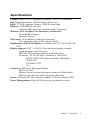
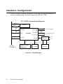
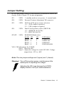
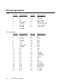
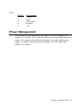
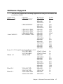
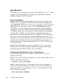
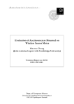
PCA-6653
Video Display Card for
Flat Panel and CRT
Copyright Notice
This document is copyrighted by Advantech Co., Ltd. All rights
are reserved. Advantech Co., Ltd., reserves the right to make
improvements to the products described in this manual at any time
without notice.
No part of this manual may be reproduced, copied, translated, or
transmitted in any form or by any means without the prior written
permission of Advantech Co., Ltd. Information provided in this
manual is intended to be accurate and reliable. However, Advantech Co., Ltd., assumes no responsibility for its use, nor for any
infringements upon the rights of third parties which may result
from its use.
All brand and product names mentioned herein are trademarks or
registered trademarks of their respective holders.
Part No. 2002665300, 1st Edition
Printed in Taiwan, September 1995
ii
Contents
Chapter 1 Introduction ..................................1
Description .............................................................................. 2
Specifications .......................................................................... 3
Display Support ...................................................................... 4
Video BIOS ............................................................................. 4
Simultaneous Display Mode .................................................. 5
Chapter 2 Hardware Setup ...........................7
Hardware Configuration ....................................................... 8
Connectors ............................................................................ 10
Jumper Setting ..................................................................... 11
Pin Assignments ................................................................... 12
Power Management ............................................................. 13
Chapter 3 Software Drivers and Utilities...15
Simultaneous Display Mode ................................................ 16
Sleep Mode ............................................................................ 16
Software Support ................................................................. 17
Driver Installation ................................................................ 18
Windows Setup ............................................................................... 19
AutoCAD R12 ................................................................................. 22
Lotus 1-2-3 and Lotus Symphony ................................................. 24
VESA ............................................................................................... 26
Word ................................................................................................ 27
WordPerfect .................................................................................... 28
iii
iv
CHAPTER
1
Introduction
Chapter 1 Introduction
1
Description
The PCA-6653 is based on the CHIPS VGA flat panel/CRT controller
and is fully IBM VGA compatible. This controller offers a large set of
extended functions and higher resolutions, and it supports simultaneous functioning. Since the PCA-6653 VGA adapter is fully compatible, you do not require any special drivers to operate in standard
modes. The enclosed software drivers allow you to take advantage of
the extended features of the PCA-6653:
High performance in Microsoft Windows
Resolutions up to 1024x768 in graphics modes with 256 colors
640x480 resolution in graphics modes with 32K, 64K, and 16M
colors
132 column text mode
Warning! Be sure to turn off the power and unplug all components before attempting to install or adjust the PCA6653. Make sure the jumpers are set correctly before
connecting the PCA-6653 to your flat panel display.
Incorrect jumper settings could damage your display.
2
PCA-6653 User's Manual
Specifications
Chipset: CHIPS 65545, integrated flat panel / CRT VGA controller
Slot: High performance 16-bit ISA-bus add-on card
BIOS: 27C010, supports 4 banks, 32KB for each bank
Memory: 1MB DRAM on board
256Kx16 DRAM socket for frame buffer (Optional)
Windows GUI (Graphic User Interface) Accelerator:
32-bit BitBLT Engine
Hardware Cursor
Wait State: 32-bit Memory read/write operation
Zero wait state (when CPU write to 66545)
Simultaneous CRT/LCD display: Available with TFT, STN, B/W, EL,
CRT
Display support: CRT - 1024x768 Non-interlaced analog or multisynch monitors with 256 colors
640x480 CRT and Panel display with 64K colors
Flat panel - TFT LCD (Max resolution is 1024x768)
DSTN /STN LCD (Max resolution is 800x600)
B/W LCD
PLASMA LCD
EL
Connector: DB-44 for Flat panel Display
DB-15 for CRT
Built-in 44-pin for general purpose connector (Pin Header)
Built-in 5-pin for keyboard connection (Housing)
Power: On-board DC-DC converter supplies LCD bias voltage (VEE)
Power Management: Chips 65545 power saving stand-by mode
Chapter 1 Introduction
3
Driver Support
The software driver provides:
Microsoft Windows 3.XX
MS DOS
AutoCAD Release 12
Lotus 1-2-3
Lotus Symphony
VESA
Microsoft Word
WordPerfect
132 Column Text Mode (only usable in WordPerfect and Wordstar)
The PCA-6653 provides 16.7M colors with a CRT output frequency
of 65 MHz.
Video BIOS
The standard BIOS chip supports four kinds of flat panel displays:
TFT LCD: Toshiba LTM09C016
DSTN LCD: Sharp LM64183P
MONO LCD: Sharp LM64C142
EL: Planar EL640.480AD4
4
PCA-6653 User's Manual
Simultaneous Display Mode
The PCA-6653 supports simultaneous display to a CRT monitor and a
flat panel display. The flat panel may be TFT, mono, DSTN, or EL.
If you use a DSTN LCD in this mode, the display must be under 16/
256 colors or the CRT and flat panel screens will tremble. You must
add a frame buffer with 512K RAM and update the BIOS setup. Call
us for assistance.
Chapter 1 Introduction
5
6
PCA-6653 User's Manual
CHAPTER
2
Hardware Setup
Chapter 2 Hardware Setup
7
Hardware Configuration
The PCA-6653 is based on chipset 65545 and has high performance, a
simple configuration, and fully supported LCD/EL/CRT.
PCA-6653 System block diagram
Address
BIOS
Data
RGB
H/V Sync
24
Address
16
Data
65540/45
Panel Data
To CRT Display
24
To Flat Panel Display
Panel Control
Power-on
Control
/ENVEE
32
16-bit
ISA BUS
1MB Video
Memory
16
512KB
Frame Buffer
Figure 2-1 Block Diagram
8
PCA-6653 User's Manual
+VEE
Sequencing
+V
-VEE
-V
DC-DC
Converter
Figure 2-2 Component / Jumper Placement
Chapter 2 Hardware Setup
9
Connectors
10
CN1
DB-15 Female for CRT monitor
CN2
DB-44 Female for flat panel display
CN3
pin-header 44-pin for flat panel display (pin to pin
compatible with CN2)
CN4
housing 5-pin for keyboard connection
PCA-6653 User's Manual
Jumper Setting
Be sure the jumper setting is correct before you install the card to the
chassis. Refer to figure 2-2 for pin assignments.
JP1
2 PIN
1: standby mode to save power , 0: normal mode
JP4
2 PIN
External Contrast Adjustment VR connector
JP5
3 PIN
VEE for LCDs power source selection
1-2 : +VEE (output is positive)
2-3 : -VEE (output is negative)
JP6
3 PIN
Panel Colock polarity select (SHFCLK)
1-2 : +SHFCLK (for LCDs)
2-3 : -SHFCLK (for EL)
JP2,JP3
2 PIN
ROM BIOS Bank select
BANK
Bank 0
Bank 1
Bank 2
Bank 3
JP2
1
0
1
0
JP3
1
1
0
0
LCD Model
LTM09C016
LM64C142
LM64183P
EL640.480AD4
VR1: VEE adjustment for LCD/EL
Step 1 - Short the JP4.
Step 2 - Adjust the voltage for each LCD VEE. Voltage
ranges from +12V to +40V
Note: The two jumper settings are 0 (open) and 1 (closed).
Warning! Turn off the system power, and disconnect the
cables prior to adjusting the voltage!
Adjusting the VR1 may damage the LCD/EL
display module. Call if you need assistance.
Chapter 2 Hardware Setup
11
Pin Assignments
CN1:
Pin No.
1
2
3
4
5
6
7
8
Descriptions
R
G
B
(Not used)
Ground
Ground
Ground
Ground
Pin No.
9
10
11
12
13
14
15
Descriptions
(Not used)
Ground
(Not used)
(Not used)
Horizontal sync
Vertical sync
(Not used)
CN2 and CN3:
Pin No.
1
2
3
4
5
6
7
8
9
10
11
12
13
14
15
16
17
18
19
20
21
22
Descriptions
+12V
+12V
Ground
Ground
+5V
+5V
VEESAFE
Ground
P0
P1
P2
P3
P4
P5
P6
P7
P8
P9
P10
P11
P12
P13
Pin No.
23
24
25
26
27
28
29
30
31
32
33
34
35
36
37
38
39
40
41
42
43
44
Descriptions
P14
P15
P16
P17
P18
P19
P20
P21
P22
P23
Ground
Ground
ASHFCLK
FLM
M
LP
Ground
ENABKL
KB_DATA
KB_CLK
C_VR1
C_VR2
12
PCA-6653 User's Manual
CN4:
Pin No.
1
2
3
4
5
Descriptions
Clock
Data
(Not used)
Ground
+5V
Power Management
To save power, you can disable the Chips 65545 by setting the JP1
jumper to 1 (closed). This clears the memory and interrupts input and
output. You can use the included software if you only want to stop
output. To disable the flat panel's backlight, set CN2-pin40 (ENABKL) to 0 (open).
Chapter 2 Hardware Setup
13
14
PCA-6653 User's Manual
CHAPTER
3
Software Drivers and
Utilities
Chapter 3 Software Drivers and Utilities
15
This chapter describes the installation and operation of the software
drivers on the included Display Driver diskette.
Simultaneous Display Mode
The 65545 VGA BIOS supports monochrome LCD, EL, color TFT
and STN LCD flat panel displays. It also supports interlaced and noninterlaced analog monitors (VGA color and VGA monochrome) in
high-resolution modes while maintaining complete IBM VGA
compatibility. Digital monitors (i.e. MDA, CGA, and EGA) are NOT
supported. Multiple frequency (multisync) monitors are supported as
analog monitors.
Both CRT and panel displays can be used simultaneously. The PCA6653 can be set in one of three configurations: on a CRT, on a flat
panel display, or on both simultaneously. The system is initially set to
simultaneous display mode. In the utility diskette, there are three
.COM files which can be used to select the display. Simply type the
filename at the DOS prompt:
CT.COM Enables CRT display only
FP.COM Enables panel display only
SM.COM Enables both displays at the same time.
Sleep Mode
The Display Driver diskette contains two files that support sleep
mode. Simply type the filename at the DOS prompt:
ON.COM switches to normal display mode.
OFF.COM switches to sleep mode.
16
PCA-6653 User's Manual
Software Support
The drivers support the following applications using the filenames and
resolutions listed:
Application
Windows 3.1
Filename
LINEAR4.DRV
LINEAR8.DRV
AutoCAD R12
LINEAR15.DRV
LINEAR16.DRV
LINEAR24.DRV
RCTURBOC.EXP
Resolution
640x480
800x600
1024x768
640x480
800x600
1024x768
640x480
640x480
640x480
640x480
800x600
1024x768
640x480
800x600
1024x768
640x480
640x480
640x480
Lotus 1-2-3 2.0 and Lotus Symphony 1.0,1.1
V132X25.DRV
132x25 (Text)
V132X50.DRV
132x50 (Text)
VESA 1.2
VESA.COM
800x600
1024x768
640x400
640x480
800x600
1024x768
640x480
640x480
Word 5.0
VGA600.VID
800x600
VGA768.VID
1024x768
Word 5.5
VGA55600.VID
800x600
VGA55768.VID
1024x768
Colors
16
16
16
256
256
256
32K
64K
16M
16
16
16
256
256
256
32K
64K
16M
16
16
16
16
256
256
256
256
32K
64K
16
16
16
16
Chapter 3 Software Drivers and Utilities
17
WordPerfect 5.0
WordPerfect 5.1
CHIPS600.WPD
CHIPS768.WPD
VGA600.VRS
VGA768.VRS
800x600
1024x768
800x600
1024x768
16
16
16
16
Driver Installation
Necessary prerequisites
The instructions in this manual assume that you understand elementary concepts of MS-DOS and the IBM Personal Computer. Before you
attempt to install any driver or utility you should: know how to copy
files from a floppy disk to a directory on the hard disk, understand the
MS-DOS directory structure, and know how to format a floppy disk.
If you are uncertain about any of these concepts, please refer to the
DOS or Windows user reference guides for more information before
you proceed with the installation.
Before you begin
Before you begin installing software drivers, you should make a
backup copy of the Display Driver diskette, and store the original in a
safe place. The Display Driver diskette contains drivers for several
versions of certain applications. You must install the correct version
in order for the driver to work properly so make sure you know which
version of the application you have.
18
PCA-6653 User's Manual
Windows Setup
These drivers are designed to work with Microsoft Windows 3.1. You
may install these drivers through Windows or in DOS.
Step 1: Install Windows as you normally would for a VGA display.
Run Windows to make sure that it is working correctly.
Step 2: Place the Display Driver diskette in drive A. In Windows
Program Manager, choose File from the Options Menu. Then from
the pull-down menu, choose Run . . . . At the command line prompt,
type A:\WINSETUP. Press the <ENTER> key or click OK to begin
the installation. At this point the setup program locates the directory
where Windows is installed. For proper operation, the drivers must be
installed in the Windows subdirectory. Press <ENTER> to complete
the installation. Once completed, the Display Driver Control Panel
appears on the screen. This Control Panel allows you to select and
load the installed drivers.
Another method of installing these drivers is through the File Manager. Click on Drive A:. Then double-click on WINSETUP.EXE to
begin installation.
Changing Display Drivers in Windows
To change display drivers in Windows, select the Windows Setup icon
from the Main window. You will be shown the current setup configuration. Select Change System Settings from the Option menu. Click
on the arrow at the end of the Display line. You will be shown a list of
display drivers. Click on the driver you want. Then click on the OK
button. Follow the directions to complete the setup.
Changing Color Schemes
After you change display drivers, you may notice that the color
scheme used by Windows looks strange. This is because different
drivers have different default colors. To change the color scheme,
select the Control Panel from the Main window. Select the Color
icon. You will be shown the current color scheme. Choose a new
color scheme and click the OK button.
Chapter 3 Software Drivers and Utilities
19
DOS Setup
Step 1: Install Windows as you normally would for a VGA display.
Run Windows to make sure that it is working correctly. Then exit
Windows.
Step 2: Place the Display Driver diskette in drive A. Type A: <ENTER> to make this the default drive. Type SETUP <ENTER> to run
the driver SETUP program. Press any key to get to the applications
list. Using the arrow keys, select Windows Version 3.1 and press the
<ENTER> key. Press the <ENTER> key to select All Resolutions,
and then press <END> to begin the installation. At this point you will
be asked for the path to your Windows System directory (default
C:\WINDOWS). When the installation is complete, press any key to
continue. Press <ESC> followed by Y to exit to DOS.
Step 3: Change to the directory where you installed Windows (usually
C:\WINDOWS).
Step 4: Type SETUP <ENTER> to run the Windows Setup program.
It will show the current Windows configuration. Use the up arrow key
to move to the Display line and press <ENTER>. A list of display
drivers will be shown. Use the arrow keys to select one of the drivers
starting with an asterisk (*) and press <ENTER>.
Step 5: Follow the directions on the screen to complete the setup. In
most cases, you may press <ENTER> to accept the suggested option.
When Setup is done, it will return to DOS. Type WIN <ENTER> to
start Windows with the new display driver.
Changing Display Drivers in DOS
To change display drivers from DOS, change to the Windows
directory and run Setup, repeating steps 4 and 5 from the previous
page. Besides the special display drivers marked by an asterisk (*),
you should be able to use the following standard drivers:
20
VGA
640x480, 16 colors
Super VGA
800x600, 16 colors
PCA-6653 User's Manual
Panning Drivers
Special panning drivers are provided to allow high-resolution modes
to be displayed on a flat panel or CRT. These drivers will show a
section of a larger screen and will automatically pan, or scroll, the
screen horizontally and vertically when the mouse reaches the edge of
the display.
Linear Acceleration Drivers
A special high-performance linear acceleration driver is provided for
256-color modes. This driver may require special hardware and may
not be supported on all systems. It is only available for Windows3.1.
Chapter 3 Software Drivers and Utilities
21
AutoCAD R12
These drivers are designed to work with Autodesk AutoCAD R12.
They conform to the Autodesk Device Interface (ADI) for Rendering
drivers and Display drivers. These display list drivers accelerate
redraw, pan, and zoom functions.
Driver installation
Step 1: Place the Display Driver diskette in drive A. Type A: <ENTER> to make this the default drive. Type SETUP <ENTER> to run
the SETUP program. Press any key to get to the applications list.
Using the arrow keys, select AutoCAD Release 12 and press <ENTER>. This will display a list of supported driver resolutions. Using
the arrow keys and the <ENTER> key, select the resolutions that are
appropriate for your monitor. When all of the desired resolutions have
been selected, press <END> to begin the installation. At this point you
will be asked for a drive and directory to copy the driver files. Enter
the drive and directory that contains the installed AutoCAD R12. If
the destination directory does not exist you will be asked for confirmation. When the installation is complete, press any key to continue.
Press <ESC> followed by Y to exit to DOS.
Step 2: Go to the AutoCAD directory where the new drivers were
installed and run the driver installation program by typing ACAD12 r <ENTER>. This program will configure your AutoCAD R12 to use
the new display drivers. Select TurboDLD Classic.
Configuring TurboDLD
Select Configure Video Display. In Display Device Configuration
choose Select Graphics Board/Resolution. Then choose Select
Display Graphics Board. After choosing a graphics board, go to
Select Display Resolution. After selecting the display resolution, save
the new configuration, and return to the main menu.
Basic Configuration Menu
This menu allows you to modify:
Number of AutoCAD Command Lines
22
PCA-6653 User's Manual
Font Size
6x8/8x8/8x14/8x16/12x20/12x24
Dual Screen
Enable/Disable
User Interface Configuration
Double Click Interval Time
BP Button
BP Highlight
Patt Line/Xor Rect/Both
BP Refresh
Enable/Disable
BP Cache
Enable/Disable
Expert Configuration Menu
This menu allows you to modify:
Display List
Enable/Disable
Drawing Cache
Enable/Disable
Use Acad 31 bit space?
Yes/No
Internal Command Echo
Enable/Disable
BP Zoom Mode
Freeze/Float
Regen Mode
Incremental/Fast
If your previously installed driver is not TurboDLD, you will have to
reconfigure the RENDER command the first time you use it.
Chapter 3 Software Drivers and Utilities
23
Lotus 1-2-3 and Lotus Symphony
These drivers are designed to work with Lotus 1-2-3 versions 2.0,
2.01 and 2.2, and with Lotus Symphony versions 1.0 and 1.1.
Driver installation
Step 1: Place the Display Driver diskette into drive A. Make A the
default drive by typing A: <ENTER>. Run the SETUP program by
typing SETUP <ENTER>. Press any key to display a list of supported
applications. Use the arrow keys to select Lotus/Symphony, and press
<ENTER>. A list of supported screen resolutions will be displayed.
Use the arrow keys to select the desired screen resolution and press
<ENTER>. (Make sure your monitor is able to display the resolution
desired) Press <END> to begin the driver installation process. A
default drive and directory path will be displayed. Use the backspace
key to erase this default and type in the 123 directory. At this point
you may be asked to create the target directory if it does not already
exist. After the files have been installed, press any key to return to the
list of supported applications. Press <ESC> followed by Y to exit to
DOS. Copy all the files that were just created in the temporary
directory onto a formatted floppy diskette.
Step 2: Go to your 123 directory, and start the installation program.
Type the following commands:
C: <ENTER>
INSTALL <ENTER>
Step 3: The Lotus installation program will load and present the
installation menu. From this menu, select Advanced Options. From
the Advanced Options menu, select Add New Drivers To Library.
From the Add New Drivers Menu, select Modify Current Driver Set.
From the Modify Driver Set Menu, select Text Display. From the Text
Display menu, select one of drivers.
Step 4: After the selection of the appropriate VGA display driver, you
will need to exit this menu and return to the Main Lotus Installation
Menu. Do this by selecting Return To Menu.
Step 5: At the Main Lotus Installation Menu, select Save Changes.
24
PCA-6653 User's Manual
Step 6: At this point the Installation Menu will prompt you for the
name of your new Lotus configuration file. The Lotus system will
prompt you with the default value — 123.SET, but you may want to
use a filename that indicates the resolution of its driver. For example,
if you installed the 132 column by 25 line driver, you could name this
driver 132X25.SET, or if you installed the 80 by 50 driver, you may
want to call the file 80X50.SET.
Step 7: The installation of your Lotus 1-2-3 driver is now complete.
You will need to exit the Lotus installation program at this point. At
the main Lotus Installation Menu, select Exit.
NOTE: If your driver set is not 123.SET, you have to type the
filename of your driver set in the command line when you start Lotus
1-2-3. For example, if you named your driver set 132X25.SET, type
the following to start Lotus 1-2-3:
123 132X25.SET <ENTER>
Chapter 3 Software Drivers and Utilities
25
VESA
The Video Electronics Standards Association (VESA) has created a
standard for a Super VGA BIOS Extension (VBE). This defines a
standard software interface to allow application programs to set and
control extended video modes, such as 800x600 graphics, on video
adapters from different manufacturers.
The VESA driver adds this Super VGA BIOS Extension to the VGA
BIOS. Any application program which supports the VESA standard
driver interface can be used with this driver. This VESA driver
conforms to the VESA Super VGA Standard #VS891001.
Driver installation
Step 1: Place the Display Driver diskette into drive A. Make A the
default drive by typing A: <ENTER>. Run the SETUP program by
typing SETUP <ENTER>. Press any key to display a list of supported
applications. Use the arrow keys to select VESA Driver Version 1.2
and press <ENTER>. Press the <ENTER> key to select All Resolutions, and press <END> to begin the installation. A default drive and
directory path will be displayed. Use the backspace key to erase this
and type in a directory that is in the directory path (such as C:\BIN or
C:\UTILS). After the files have been installed, press any key to return
to the list of supported applications. Press <ESC> followed by Y to
exit to DOS.
Step 2: To install the VESA driver, type either VESA <ENTER> or
VESA + <ENTER> at the DOS prompt. The optional + command line
parameter enables all of the available modes. Make sure that your
monitor is capable of displaying these high resolution modes before
enabling them.
NOTE: If the video BIOS already supports VBE extended video
modes, DO NOT use this driver. Run the VTEST.EXE program to see
if the video BIOS supports the VBE modes.
26
PCA-6653 User's Manual
Word
These drivers are designed to work with Microsoft Word 5.0 and 5.5.
Driver installation
If you have already installed Word on your computer, go to Step 2 to
install the new video driver.
Step 1: Install Word as normal.
Step 2: After you complete the Word installation, place the Display
Driver diskette into drive A. Make A the default drive by typing A:
<ENTER>. Run the SETUP program by typing SETUP <ENTER>.
Press any key to display a list of supported applications. Use the
arrow keys to select Word and press <ENTER>. Use the arrow keys
to select the desired screen resolution and press <ENTER> (make sure
your monitor is able to display the resolution desired). Press <END>
to begin the driver installation process. A default drive and directory
path will be displayed. Use the backspace key to erase this and type in
your Word directory. After the files have been installed, press any key
to return to the list of supported applications. Press <ESC> followed
by Y to exit to DOS.
Step 3: Copy the driver file for the desired resolution that was just
installed to SCREEN.VID. (The driver file names are listed on pages
12-13.)
Chapter 3 Software Drivers and Utilities
27
WordPerfect
These drivers are designed to work with WordPerfect 5.0 or 5.1. They
support 132-column display in editing mode, and high-resolution
graphics display in PreView mode.
Driver installation
Step 1: Place the Display Driver Diskette into drive A. Make A the
default drive by typing A: <ENTER>. Run the SETUP program by
typing SETUP <ENTER>. Press any key to display a list of supported
applications. Use the arrow keys to select WordPerfect and press
<ENTER>. A list of supported screen resolutions will be displayed.
Use the arrow keys to select the desired screen resolution and press
<ENTER> (make sure your monitor is able to display the resolution
desired). Press <END> to begin the driver installation process. A
default drive and directory path will be displayed. Use the backspace
key to erase this default and type in the WordPerfect directory. At
this point you may be asked to create the target directory if it does not
already exist. After the files have been installed, press any key to
return to the list of supported applications. Press <ESC> followed by
Y to exit to DOS.
Step 2: Start WordPerfect, and press <SHIFT>+<F1> to enter the
setup menu. Select D for Display and G for Graphics Screen Type,
and then choose the desired Chips VGA resolution.
Configuring WordPerfect 5.0 for 132 columns
Follow these instructions to configure WordPerfect 5.0 for 132
column text mode:
Step 1: To use the SETCOL program to set 132 columns and 25 rows,
type the following command:
SETCOL 132, 25 <ENTER>
Step 2: Start WordPerfect. The program will detect the number of
rows and columns automatically. If for some reason WordPerfect is
unable to adapt to 132 columns by 25 rows, start WordPerfect with
the following command:
WP /SS=25,132 <ENTER>
28
PCA-6653 User's Manual
Configuring WordPerfect 5.1 for 132 columns
Start WordPerfect and press <SHIFT>+<F1> to enter the setup menu.
Select D for Display and T for Text Screen Type and then select
Chips 132 Column Text.
Chapter 3 Software Drivers and Utilities
29
30
PCA-6653 User's Manual