1
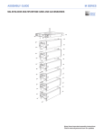
assembly guide m series MG-3D/M Multipurpose Grid and Accessories Keep these important assembly instructions. Check www.meyersound.com for updates. Refer to the MILO 120 Operating Instructions for additional information on that product. © 2007 Meyer Sound. All rights reserved. MG-3D/M Multipurpose Grid and Accessories Assembly Guide The contents of this manual are furnished for informational purposes only, are subject to change without notice, and should not be construed as a commitment by Meyer Sound Laboratories Inc. Meyer Sound assumes no responsibility or liability for any errors or inaccuracies that may appear in this manual. Except as permitted by applicable copyright law, no part of this publication may be reproduced, stored in a retrieval system, or transmitted, in any form or by any means, electronic, mechanical, recording or otherwise, without prior written permission from Meyer Sound. AlignaLink, M3D, and all alphanumeric product designations are trademarks of Meyer Sound. Meyer Sound, MILO, and QuickFly are registered trademarks of Meyer Sound Laboratories Inc. (Reg. U.S. Pat. & Tm. Off.). All third-party trademarks mentioned herein are the property of their respective trademark holders. Printed in the U.S.A. Part Number: 05.132.036.01 B2 MG-3D/M multipurpose grid and Accessories CONTENTS This Assembly Guide provides instructions on how to safely assemble and use the MG-3D/M multipurpose grid and accessories. In addition to descriptions of the MG-3D/M grid's major components, this guide will show you how the components work together, with examples of common uses. 1.General Information.............................................................................................................................................5 Safety Statement....................................................................................................................................................5 MG-3D/M Multipurpose Grid Overview . ...............................................................................................................7 Load Ratings Overview..........................................................................................................................................8 2.Using MILO® with the MG-3D/M Grid.................................................................................................................9 MILO System Load Ratings and Pickup Configurations........................................................................................9 Using One or Both Center Points....................................................................................................................9 Using All Four Corner Points.........................................................................................................................10 MLK-MILO Link Kit...............................................................................................................................................12 MG-3D/M Grid and MILO Rear Flown Configuration...........................................................................................13 MG-3D/M Grid and MILO Front Flown Configuration..........................................................................................14 MILO Ground-Supported Configurations . ..........................................................................................................15 3.Using M3D/M3D-Sub with the MG-3D/M Grid.................................................................................................16 M3D System Load Ratings and Pickup Configurations.......................................................................................16 Using One or Both Center Points..................................................................................................................16 Using All Four Corner Points.........................................................................................................................17 MLK-3D Link Kit...................................................................................................................................................19 MG-3D/M Grid and M3D/M3D-Sub Rear Flown Configuration...........................................................................20 MG-3D/M Grid and M3D/M3D-Sub Front Flown Configuration..........................................................................21 M3D/M3D-Sub Ground-Supported Configurations ............................................................................................22 4: Transitions and Accessories ............................................................................................................................23 MTR-3D/M Transition Rail Kit: M3D/M3D-Sub to MILO.......................................................................................23 MTB-2D/M Transition Bar Kit: MILO to M2D........................................................................................................25 MTK-2D Transition Kit: M3D/M3D-Sub to M2D...................................................................................................26 PBF-MILO Pull-Back Frame.................................................................................................................................27 MVE-MILO Vertical Extension Bars......................................................................................................................28 MCF-MILO Caster Frame Kit................................................................................................................................29 Meyer Sound Laboratories Inc. www.meyersound.com T: +1 510 486.1166 F: +1 510 486.8356 PN: 05.132.036.01 B2 Page of 32 MG-3D/M multipurpose grid and Accessories Meyer Sound Laboratories Inc. www.meyersound.com T: +1 510 486.1166 F: +1 510 486.8356 PN: 05.132.036.01 B2 Page of 32 MG-3D/M multipurpose grid and Accessories 1.General Information Safety Statement Please read this Statement carefully and in its entirety. It contains important information regarding safety issues, including guidelines for general safe use of rigging systems as well as advisories on government regulations and liability laws. SCOPE OF THIS MANUAL Although this manual contains much useful information on rigging in general, it does not claim to be a comprehensive resource on the subject. This manual assumes that the owners and/or users of a QuickFly system are knowledgeable and experienced in the areas of rigging and flying loudspeaker systems. Many issues of crucial concern, such as the determination of appropriateness and condition of venue rigging points, cannot be addressed here. Therefore, the user must assume all responsibility for the appropriate use of QuickFly systems in any particular location or circumstance. The suspension of large, heavy objects in public places is subject to numerous laws and regulations at the national/federal, state/provincial, and local levels. This manual does not address the specifics of any such applicable laws and government regulations. This manual details procedures and practices consistent with those generally acknowledged as allowable and safe in the United States. However, the user must assume responsibility for making sure that use of any QuickFly system and its components in any particular circumstance or venue conforms to all applicable laws and regulations in force at the time. LOAD RATINGS AND SPECIFICATIONS Long-term safe operation is a central concern in the design and manufacture of any rigging/flying system. Meyer Sound has taken great care in material selection and component design. After manufacture, all load-critical system components are individually inspected. All load ratings and other specifications given in this manual are the result of accepted engineering practice and careful testing. However, such specifications and ratings are subject to change. Users SHOULD check the QuickFly section of the Meyer Sound web site at http://www.meyersound.com or contact Technical Support at regular intervals to check for updated or revised information. REGULATORY COMPLIANCE The design and safe working load (SWL) ratings of the QuickFly system are intended to be in compliance with all known regulatory statutes currently applicable in the United States. Unless otherwise specified, all working loads are based on either a 5:1 or 7:1 safety factor. However, as noted above, there are wide variations internationally in the regulations and practices applying to suspension of sound systems in public places. Although regulations in the United States are generally among the most stringent, safety codes may be even stricter in a few localities (such as those highly prone to earthquakes). In addition, applicable safety codes are open to interpretation: Government officials in one location may have a stricter interpretation than another local official, even when operating under the same regulations and in the same legal jurisdiction. Consequently, users of QuickFly rigging systems should be prepared to take additional safety assurance measures beyond those outlined in this manual. In all cases, it is the responsibility of the user to make certain that any Meyer Sound loudspeaker system is suspended in accordance with all applicable national/federal, state/provincial, and local regulations. Meyer Sound Laboratories Inc. www.meyersound.com T: +1 510 486.1166 F: +1 510 486.8356 PN: 05.132.036.01 B2 Page of 32 MG-3D/M multipurpose grid and Accessories Safety Responsibilities “Above the Hook” In most touring applications of rigging systems, the touring sound provider is normally responsible for ensuring the safety of the suspension system only below the attachment point. The safety and suitability of the attachment point is generally seen as the responsibility of the venue owner or operator. However, this distinction (“above the hook” versus “below the hook”) can be open to interpretation. Touring system operators should double-check to make certain that attachment points are approved and suitably load rated, and that the points used are those identified as such by the venue owner or operator. As an extra precaution, careful inspection of the attachment points is advised before flying, particularly in older venues or those hosting frequent events using large sound and lighting systems. In any case, Meyer Sound QuickFly systems are intended only for suspension from approved rigging points, each known to have ample SWL margins for the system components suspended below them. INSPECTION AND MAINTENANCE The Meyer Sound QuickFly systems are an assembly of mechanical devices, and are therefore subject to wear and tear over prolonged use, as well as damage from corrosive agents, extreme impact, or inappropriate use. Because of the safety issues involved, users must adopt and adhere to a schedule of regular inspection and maintenance. In touring applications, key components must be inspected before each use. Such inspection includes examination of all load-bearing components for any sign of undue wear, twisting, buckling, cracking, rusting, or other corrosion. In regard to rust and corrosion, the main components of a QuickFly system are either protected by an exterior coating or made from stainless steel, which is impervious to rust and resistant to most corrosive fluids. Nevertheless, normal use and shipping vibrations can wear through the protective coatings, and extremely corrosive fluids (such as battery acid) can cause severe damage with prolonged exposure even to protected parts. Particular attention should be given to screws, bolts, and other fasteners to make certain the fittings are tight and secure. Metal seams and welds should be examined for any sign of separation or deformation. Meyer Sound strongly recommends that written documentation be maintained on each QuickFly system, noting date of inspection, name of inspector, points of system checked, and any anomalies discovered. Annual Comprehensive Examination and Test Program In addition to routine checks on the road for touring systems, Meyer Sound also recommends a careful, comprehensive system examination and testing “at home” in the warehouse or other appropriate location at regular intervals. Such at home examinations and tests should occur at least once a year, and should include a careful inspection of each component under ideal lighting conditions, and then a final comprehensive check of the entire system after it has been flown. If any anomalies or defects are discovered that could possibly affect the safety or integrity of the system, affected parts or subsystems should be replaced in their entirety before that part of the system is flown again. REPLACEMENT PARTS Any component found to be defective, or any safety-related component you even suspect might be defective, should be replaced with the equivalent, approved part. Parts specific to a QuickFly system should be ordered directly from Meyer Sound. No attempt should be made to substitute what appears to be equivalent or “mostly the same” generic replacements. Some parts used in QuickFly systems are identical to those used in other rigging applications. To the best of our knowledge, most of these suppliers are reputable and their products are reliable. However, Meyer Sound has no way of assuring the quality of products made by these various suppliers. Therefore, Meyer Sound is not responsible for problems caused by components that were not supplied by Meyer Sound. TRAINING QuickFly systems are relatively straightforward and easy to use. However, they should only be used by persons trained in the use of loudspeaker rigging systems who have mastered key points of assembly, rigging and flying. Users should read this manual in its entirety before attempting to deploy any QuickFly system. You may make additional copies of this manual as necessary for in-house use; copies may not be made for any other purpose. Meyer Sound Laboratories Inc. www.meyersound.com T: +1 510 486.1166 F: +1 510 486.8356 PN: 05.132.036.01 B2 Page of 32 MG-3D/M multipurpose grid and Accessories MG-3D/M Multipurpose Grid Overview The MG-3D/M multipurpose grid allows multiple MILO® high-power curvilinear array loudspeakers and/or M3D line array loudspeakers (or M3D-Sub directional subwoofers) to be flown or ground-supported in numerous configurations. List of Contents: Mg-3d/m Multipurpose Grid Kit (Part 40.132.035.01) Required for use with MILO loudspeaker(s) Qty Part Number Description 1 40.132.035.01 MG-3D/M Multipurpose Grid Assembly 4 124.078 Stainless Steel Leveling Foot MG-3D/M Multipurpose Grid Dimensions: MG-3D/M Multipurpose Grid Weight: 275 lbs (124.74 kg) Meyer Sound Laboratories Inc. www.meyersound.com T: +1 510 486.1166 F: +1 510 486.8356 PN: 05.132.036.01 B2 Page of 32 MG-3D/M multipurpose grid and Accessories Load Ratings Overview The MG-3D/M multipurpose grid can accommodate a variety of different pickup configurations using its six pickup points (three on each side of the frame). All of the load ratings in this assembly guide take the following into consideration: The angle of the bridle at the apex is no greater than 90 degrees. The weight of the MG-3D/M grid itself has been included. The maximum number of MILO loudspeakers that may be hung in each configuration is based on the MILO weight of 235 lbs (106.60 kg). The maximum number of M3D/M3D-Sub loudspeakers that may be hung is based on the M3D weight of 415 lbs (188.24 kg) and the M3D-Sub weight of 395 lbs (179.17 kg). The load ratings and maximum weights allowed regard the MG-3D/M grid and flown loudspeakers as a system, including links and pins. Thus, the maximum stress point could change from one element to another in the system. CAUTION: Using a bridle leg shorter than the recommended length for each configuration will reduce the load rating and may damage the MG-3D/M grid. CAUTION: Always use properly rated rigging hardware. The use of 3/4" shackles for the MG-3D/M grid's pick-up points is recommended. When flying an array of loudspeakers as discussed in this guide, the entire weight of the array can shift completely to either the front or back motor or set of motors; the degree of shift depends on the splay between individual cabinets in the array, the number of cabinets, and the angle of the MG-3D/M grid. Accordingly, this guide rates the MG-3D/M rigging system for the "worst case" loadings that can occur at the final trim of an array while maintaining a 5:1 or 7:1 safety factor. Configurations using angled bridles are shown with an angle at the apex of 90 degrees, resulting in the two angles between the bridle and MG-3D/M grid at the prescribed bridle length (45 degrees each). With the use of transition accessories, you can also integrate other M Series loudspeakers with MILO or M3D/M3DSub loudspeakers, to form combined arrays such as: M3D/M3D-Sub and MILO MILO and M2D M3D and M2D M3D, MILO and M2D CAUTION: The weight of any additional items hung with the array, such as downfill loudspeakers and transition accessories and cable, must be considered when calculating maximum load. Meyer Sound Laboratories Inc. www.meyersound.com T: +1 510 486.1166 F: +1 510 486.8356 PN: 05.132.036.01 B2 Page of 32 MG-3D/M multipurpose grid and Accessories 2.Using MILO with the MG-3D/M Grid MILO System Load Ratings and Pickup Configurations Using one or both center pickup points Figure 2.1. 2 to 2 center point configuration Figure 2.2. 2 to 1 center point configuration Figure 2.3. 3 to 2 center/corner point configuration Figure 2.4. 3 to 2 corner/center point configuration Max. Suspended Weight and Quantity of MILO Loudspeakers, Using Center Pickup Points Grid Tilt in Degrees Min. Bridle Leg Length Max. Weight ±0 to 45 3 ft (915 mm) ±46 to 90 3 ft (915 mm) Meyer Sound Laboratories Inc. www.meyersound.com T: +1 510 486.1166 F: +1 510 486.8356 5:1 Safety Factor 7:1 Safety Factor Max. Quantity Max. Weight Max. Quantity 4700 lbs (2131 kg) 18 (see note 1 on page 11) 3350 lbs (1520 kg) 13 (see note 1 on page 11) 3570 lbs (1619 kg) 14 2700 lbs (1225 kg) 10 PN: 05.132.036.01 B2 Page of 32 MG-3D/M multipurpose grid and Accessories MILO System Load Ratings and Pickup Configurations Using all four corner pickup points Figure 2.5. 4 to 2 corner point configuration Figure 2.6. 4 to 4 corner point configuration1 Figure 2.7. 4 to 2 corner cross point configuration Figure 2.8. 4 to 1 corner point configuration2 Max. Suspended Weight and Quantity of MILO Loudspeakers, Using Corner Pickup Points Grid Tilt in Degrees Min. Bridle Leg Length 5:1 Safety Factor ±0 to 45 3 ft (915 mm)2 6000 lbs (2722 kg) 24 5250 lbs (2381 kg) 21 (see note 2 on page 11) ±46 to 90 3 ft (915 mm)2 3570 lbs (1619 kg) 14 2700 lbs (1225 kg) 10 Max. Weight 7:1 Safety Factor Max. Quantity Max. Weight Max. Quantity 1 Please note that the bridle legs are not required in this configuration; the motors can be connected directly to the MG-3D/M grid using shackles. 2 The minimum bridle leg length for the 4 to 1 corner point configuration is 4 ft (1219 mm). Meyer Sound Laboratories Inc. www.meyersound.com T: +1 510 486.1166 F: +1 510 486.8356 PN: 05.132.036.01 B2 Page 10 of 32 MG-3D/M multipurpose grid and Accessories NOTE 1: For center point configurations, up to 24 MILO loudspeakers with a 5:1 safety factor or 17 MILO loudspeakers with a 7:1 safety factor can be flown only under the following conditions: Monitoring of the stress load on the two rigging points is done with load cells between the hoist and the MG-3D/M multipurpose grid, so that either the front or back pickup point used to hang the MG3D/M does not exceed 4700 lbs (2131 kg) at 5:1 or 3350 lbs (1520 kg) at 7:1 on the center pick-up hole. The total load must be calculated so that it is spread between the front and back points at the final array position (grid angle and accumulative splay angle of the system) and does not exceed the above stated weights on either the front or rear point. An MG-3D/M grid plus 24 MILO loudspeakers weighs approximately 6000 lbs (2721.55 kg). As long as that total weight is split between the front and rear points so that neither point supports more than 4700 lbs (2131 kg) at 5:1 or 3350 lbs (1520 kg) at 7:1, the safety factor is maintained. NOTE 2: For corner point configurations, up to 24 MILO loudspeakers at a 7:1 safety factor can be flown only under the following conditions: Monitoring of the stress load on the front and back rigging points is done with load cells between the hoist and the MG-3D/M multipurpose grid, so that either the front or back set of points used to hang the MG-3D/M do not exceed the total weight load of 5250 pounds (2381.36 kg). The total load must be calculated so that it is spread between the front and back points at the final array position (grid angle and cumulative splay angle of the system) and does not exceed the above stated weight on either the front or rear set of points. An MG-3D/M grid plus 24 MILO loudspeakers weighs approximately 6000 pounds (2721.55 kg). As long that total weight is split between the front and rear set of points so that neither set supports more than 5250 pounds (2381.36 kg), the 7:1 safety factor is maintained. NOTE: Use the Meyer Sound array rigging calculator to compute center-of-gravity data and load distribution between front and back points. Visit www.meyersound.com/arraycalculator to download. CAUTION: This calculator has been found to match actual load cell measurements to within 16% of the total weight of the array, and within 3.5 degrees of top grid angle. Meyer Sound Laboratories Inc. www.meyersound.com T: +1 510 486.1166 F: +1 510 486.8356 PN: 05.132.036.01 B2 Page 11 of 32 MG-3D/M multipurpose grid and Accessories MLK-MILO Link Kit The MLK-MILO link kit is required to attach a MILO loudspeaker to the MG-3D/M multipurpose grid. In flown configurations, the first MILO loudspeaker in the array is always connected to the MG-3D/M grid at 0°. In ground-supported configurations, the first MILO loudspeaker in the array can have from –1° to 4° in relation to the MG-3D/M grid. In both flown and ground-supported configurations, MILO loudspeakers in an array may be individually splayed at nine different tilt angles from 0° to 5° (0°, .5°, 1°, 1.5°, 2°, 2.5°, 3°, 4°, 5°), through the selection of the pin positions in accordance with your system design. Labels on the MG-3D/M grid show the correct orientation of the MG-3D/M grid for a flown or ground-supported configuration, and the front and rear positions for both MILO and M3D/M3D-Sub loudspeakers. In addition, please note that: The orientation of the MG-3D/M grid for a ground-supported configuration is a 180° (flipped) rotation from the flown position. For MILO loudspeakers, the front side of the MG-3D/M grid is opposite the side used for flying M3D/M3D-Subs. List of Contents: MLK-MILO Link Kit (Part 40.132.125.01) Required for use with MILO loudspeaker(s) Qty Part Number Description 2 61.132.027.03 MFAL-MILO Front AlignaLink 2 61.132.028.01 MRAL-MILO Rear AlignaLink 6 134.023 3/8" x 1.5" Quick Release Pin (QRP)* *Includes lanyard and necessary hardware to fix the pin to the MG-3D/M NOTE: Do not confuse the 3/8" x 1.5" QRPs included with the MLK-MILO link kit with the standard QRPs used for connecting MILO loudspeakers to each other. The standard MILO end frame QRPs are shorter and will not lock properly. In addition to being longer, the MLK-MILO kit’s QRPs are distinguished by a red release button (standard MILO QRPs are blue or black), and include a lanyard for securing each pin to the MG-3D/M grid (via small screw holes on the inside of the grid). By permanently affixing the QRPs to the MG-3D/M grid using the lanyards, you can ensure that the correct QRPs are always used. NOTE: The MFAL-MILO front and MRAL-MILO rear AlignaLinks are the same ones used between individual MILO cabinets in a MILO array. Always use all three pins in the triangular front AlignaLink, just as you would when connecting MILO cabinets together. Meyer Sound Laboratories Inc. www.meyersound.com T: +1 510 486.1166 F: +1 510 486.8356 PN: 05.132.036.01 B2 Page 12 of 32 MG-3D/M multipurpose grid and Accessories MG-3D/M Grid and MILO Rear Flown configuration The MG-3D/M multipurpose grid allows you to fly MILO loudspeakers in two positions in relation to the MG-3D/M grid. The “rear flown” position is achieved by rigging MILO loudspeakers using the holes for the AlignaLinks that are closer to the rear of the MG-3D/M grid. This position is most useful for achieving superior up tilt in the MG-3D/M grid and, subsequently, the array. Under the same circumstances (number of loudspeakers, angle between loudspeakers, rating and position of motors) the rear configuration will allow more degrees of up tilt than a "front flown" configuration. In flown configurations, the first cabinet in the array is always connected to the MG-3D/M grid at 0°. This is accomplished by using the top center hole in the rear AlignaLink (when used between cabinets, it is the 1° hole) which effectively provides a 0° tilt angle. In addition to the splay angles of individual MILO loudspeakers in an array, the up and down tilt of the MG-3D/M grid and the complete array hung underneath can additionally be adjusted using chain motors, or differing lengths of steel cables or chains. CAUTION: Out of the MRAL-MILO rear AlignaLink’s nine holes, you must use the top center hole between the MG-3D/M grid and the first MILO loudspeaker in a flown configuration to ensure a 0° splay angle between the MG-3D/M and the first MILO. Any other confinguration is not rated, and may produce an unpredictable tilt angle and/or cause damage to the link and MG-3D/M grid. Install the MRAL-MILO rear AlignaLinks and MFAL-MILO front AlignaLinks as shown into the MG-3D/M grid, using the 3/8" x 1.5" quick release pins (QRPs). CAUTION: The leveling feet must always be detached from the MG-3D/M grid before flying a system. Unscrew the entire assembly, including the threaded leg, and remove completely. CAUTION: Make sure that the long 1.5" QRPs are used to secure the AlignaLinks to the MG-3D/M grid and that the QRPs lock into place. CAUTION: Never exceed the load rating of the MG-3D/M grid. When flying an array from the MG-3D/M grid, it must always be supported by at least two pick-up holes, one on each side of the grid frame. See “MILO System Load Ratings and Pickup Configurations” earlier in this chapter for more details. Meyer Sound Laboratories Inc. www.meyersound.com T: +1 510 486.1166 F: +1 510 486.8356 PN: 05.132.036.01 B2 Page 13 of 32 MG-3D/M multipurpose grid and Accessories MG-3D/M Grid and MILO Front Flown configuration The MG-3D/M multipurpose grid allows you to fly MILO loudspeakers in two positions in relation to the grid. The "front flown" position is achieved by rigging MILO loudspeakers using the holes for the AlignaLinks that are closer to the front of the grid. This position is most useful for achieving superior down tilt in the MG-3D/M grid and, subsequently, the array. Under the same circumstances (number of loudspeakers, angle between loudspeakers, rating and position of motors) the front flown position will allow more degrees of down tilt than a "rear flown" configuration. In flown configurations, the first cabinet is connected to the MG-3D/M grid at 0°. This is accomplished by using the top center hole in the MRAL-MILO rear AlignaLink (when used between cabinets, it is the 1° hole), which effectively provides a 0° tilt angle. In addition to the splay angles of individual loudspeakers in an array, the up and down tilt of the MG-3D/M grid and the array hung underneath can additionally be adjusted using chain motors, or differing lengths of steel cables or chains. If a severe down tilt is needed, use the array rigging calculator to determine if the PBF-MILO pull back frame and a separate motor are required. Visit www.meyersound.com/arraycalculator to find out how to download the calculator. NOTE: To install a large array requiring severe vertical splay angles between cabinets, it’s useful to temporarily introduce up tilt to the MG-3D/M grid as you connect individual cabinets to each other. Depending on the application, a “rear flown” position may make more sense in this case. CAUTION: Out of the MRAL-MILO rear AlignaLink’s nine holes, you must use the top center hole between the MG-3D/M grid and the first MILO loudspeaker in a flown configuration to ensure a 0° splay angle between the MG-3D/M and the first MILO. Doing otherwise may force the hardware into an unnatural position, which may produce an unpredictable tilt angle and/or cause damage to the link and MG-3D/M grid. Install the MRAL-MILO rear and MFAL-MILO front AlignaLinks as shown into the MG-3D/M grid, using the 3/8" x 1.5" quick release pins (QRPs). CAUTION: The leveling feet must always be detached from the MG-3D/M grid before flying a system. Unscrew the entire assembly, including the threaded leg, and remove completely. CAUTION: Be sure to use the long 1.5" QRPs to secure the AlignaLinks to the MG-3D/M grid and that the QRPs lock into place. CAUTION: Never exceed the load rating of the MG-3D/M grid. When flying an array from the MG-3D/M, it must always be supported by at least two pick-up holes, one of each side of the grid frame. See “MILO System Load Ratings and Pickup Configurations” earlier in this chapter for more details. Meyer Sound Laboratories Inc. www.meyersound.com T: +1 510 486.1166 F: +1 510 486.8356 PN: 05.132.036.01 B2 Page 14 of 32 MG-3D/M multipurpose grid and Accessories MILO Ground-supported Configurations By simply flipping the MG-3D/M multipurpose grid over from its flown configuration and installing the levelling feet, the MG-3D/M grid can be used to provide ground support for a MILO array. The MG-3D/M grid provides two positions — front and rear. Either position may be used to stack MILO loudspeakers, although the front position is most useful for stacking a predominantly up tilted MILO array. In ground-supported configurations, MFAL-MILO front AlignaLinks and MRAL-MILO rear AlignaLinks connect the MG-3D/M grid to the first MILO with the same vertical orientation used as if the MG-3D/M were simply another MILO cabinet, providing from –1° to 4° up tilt between the MG-3D/M grid and the first loudspeaker when using a MILO loudspeaker as the first element of the array. NOTE: The angles engraved on a MILO rigging frame guide you when setting the splay angles between MILO cabinets. To set the angle between the MG-3D/M grid and the first MILO in your groundsupported array, the actual angle is the engraved angle minus 1°. For example, if you set the angle to the 5° hole, the actual angle between the MG-3D/M grid and the MILO will be 4° of up tilt. Install the MFAL-MILO front and MRAL-MILO rear AlignaLinks as shown into the MG-3D/M grid, using the 3/8" x 1.5" quick release pins (QRPs). CAUTION: For safety reasons, ground-supported arrays of more than six MILO loudspeakers using the MG-3D/M grid should be avoided. Larger stacks can be unstable, especially in windy conditions and on uneven ground. CAUTION: When ground supporting a MILO array on an MG-3D/M grid, always keep the center of gravity within the footprint of the leveling feet. To further secure larger arrays – particularly in outdoor situations – use tie down straps or extra ballast weight on the MG-3D/M grid. Meyer Sound Laboratories Inc. www.meyersound.com T: +1 510 486.1166 F: +1 510 486.8356 PN: 05.132.036.01 B2 Page 15 of 32 MG-3D/M multipurpose grid and Accessories 3.Using M3D/M3D-Sub with the mg-3d/m Grid M3D System Load Ratings and Pickup Configurations Using one or both center pickup points Figure 3.1. 2 to 2 center point configuration Figure 2.2. 2 to 1 center point configuration Figure 3.3. 3 to 2 center/corner point configuration Figure 3.4. 3 to 2 corner/center point configuration Max. Suspended Weight and Quantity of M3D Loudspeakers, Using Center Pickup Points Grid Tilt in Degrees Min. Bridle Leg Length 5:1 Safety Factor Max. Weight ±0 to 45 3 ft (915 mm) 4700 lbs (2131 kg) 7:1 Safety Factor Max. Quantity Max. Weight Max. Quantity 10 (see note 1 on page 18) 7 (see note 1 on page 18) 3350 lbs (1520 kg) +45 Not Allowed Meyer Sound Laboratories Inc. www.meyersound.com T: +1 510 486.1166 F: +1 510 486.8356 PN: 05.132.036.01 B2 Page 16 of 32 MG-3D/M multipurpose grid and Accessories M3D System Load Ratings and Pickup Configurations Using all four corner pickup points Figure 3.5. 4 to 2 corner point configuration Figure 3.6. 4 to 4 corner point configuration1 Figure 3.7. 4 to 2 corner cross point configuration Figure 3.8. 4 to 1 corner point configuration2 Max. Suspended Weight and Quantity of M3D Loudspeakers, Using Corner Pickup Points Grid Tilt in Degrees Min. Bridle Leg Length 5:1 Safety Factor ±0 to 45 3 ft (915 mm) Max. Weight 2 6000 lbs (2722 kg) 7:1 Safety Factor Max. Quantity Max. Weight Max. Quantity 13 (see note 2 on page 18) 11 (see note 2 on page 18) 5250 lbs (2381 kg) +45 Not Allowed 1 Please note that the bridle legs are not required in this configuration; the motors can be connected directly to the MG-3D/M grid using shackles. 2 The minimum bridle leg length for the 4 to 1 corner point configuration is 4 ft (1219 mm). Meyer Sound Laboratories Inc. www.meyersound.com T: +1 510 486.1166 F: +1 510 486.8356 PN: 05.132.036.01 B2 Page 17 of 32 MG-3D/M multipurpose grid and Accessories NOTE 1: For center point configurations, up to 14 M3D loudspeakers with a 5:1 safety factor or 10 M3D loudspeakers with a 7:1 safety factor can be flown only under the following conditions: Monitoring of the stress load on the two rigging points is done with load cells between the hoist and the MG-3D/M multipurpose grid, so that either the front or back pickup point used to hang the MG3D/M does not exceed 4700 lbs (2131 kg) at 5:1 or 3350 lbs (1520 kg) at 7:1 on the center pick-up hole. The total load must be calculated so that it is spread between the front and back points at the final array position (grid angle and accumulative splay angle of the system) and does not exceed the above stated weights on either the front or rear point. The MG-3D/M grid plus 14 M3D loudspeakers weighs approximately 6000 lbs (2721.55 kg). As long as that total weight is split between the front and rear points so that neither point supports more than 4700 lbs (2131 kg) at 5:1 or 3350 lbs (1520 kg) at 7:1, the safety factors are maintained. NOTE 2: For corner point configurations, up to 16 M3D loudspeakers at a safety factor of 5:1 and 7:1 can be flown only under the following conditions: Monitoring of the stress load on the four rigging points is done with load cells between the hoist and the MG-3D/M multipurpose grid, so that either the front or back set of points used to hang the MG-3D/M grid do not exceed the total weight load of 6000 lbs (2721.55 kg) at 5:1 or 5250 pounds (2381.36 kg) at 7:1. The total load must be calculated so that it is spread between the front and back points at the final array position (grid angle and cumulative splay angle of the system) and does not exceed the above stated weights on either the front or rear set of points. The MG-3D/M grid plus 16 M3D loudspeakers weighs approximately 7000 lbs (3175.15 kg). As long that total weight is split between the front and rear set of points so that neither set supports more than 6000 lbs (2721.55 kg) at 5:1 or 5250 pounds (2381.36 kg) at 7:1, the safety factors are maintained. NOTE: Use the Meyer Sound array rigging calculator to compute center-of-gravity data and load distribution between front and back points. Visit www.meyersound.com/arraycalculator to download. CAUTION: This calculator has been found to match actual load cell measurements to within 16% of the total weight of the array, and within 3.5 degrees of top grid angle. Meyer Sound Laboratories Inc. www.meyersound.com T: +1 510 486.1166 F: +1 510 486.8356 PN: 05.132.036.01 B2 Page 18 of 32 MG-3D/M multipurpose grid and Accessories MLK-3D Link Kit The MLK-3D link kit is required to attach an M3D/M3D-Sub to the MG-3D/M multipurpose grid. In flown configurations, the first M3D/M3D-Sub cabinet in the array is always connected to the MG-3D/M grid at 0°. In ground-supported configurations, the first M3D/M3D-Sub cabinet in the array can have from 0° to 5° with respect to the MG-3D/M grid. In both flown and ground-supported configurations, M3D/M3D-Sub cabinets may be individually splayed from 0° to 5° through the selection of pin positions in accordance with your system design. The up and down tilt of the MG-3D/M grid and the complete array hung underneath can additionally be adjusted using chain motors, or differing lengths of steel cables or chain lengths. CAUTION: Always use two quick release pins (QRPs) to secure the front MTL-3D transition links to the MG-3D/M grid. Labels on the left and right sides of the MG-3D/M grid denote the correct orientation of the grid for a flown or groundsupported configuration, as well as the front and rear positions for both MILO and M3D/M3D-Sub loudspeakers. In addition, please note that: The orientation of the MG-3D/M grid for a ground-supported configuration is a 180° (flipped) rotation from the flown position. For M3D/M3D-Subs, the front side of the MG-3D/M grid is opposite the side used for flying MILO loudspeakers. List of Contents: MLK-3D Link Kit (Part 40.132.120.01) Required for use with M3D/M3D-Sub loudspeaker(s) Qty Part Number Description 2 61.132.115.02 MTL-3D Transition Link 6 134.007 1/2" x 2.5" QRP* Meyer Sound Laboratories Inc. www.meyersound.com T: +1 510 486.1166 F: +1 510 486.8356 *Includes lanyard and necessary hardware to fix the pin to the MG-3D/M PN: 05.132.036.01 B2 Page 19 of 32 MG-3D/M multipurpose grid and Accessories MG-3D/M Grid and M3D/M3D-sub Rear Flown configuration The MG-3D/M multipurpose grid allows you to fly M3D/M3D-Sub loudspeakers in two positions with respect to the grid. The “rear flown” position is achieved by rigging M3D/M3D-Sub loudspeakers using the holes for the captive links that are closer to the rear of the MG-3D/M. The rear flown position is highly useful for achieving superior up tilt in the MG-3D/M grid and, subsequently, the array. Under the same circumstances (number of loudspeakers, angle between loudspeakers, rating and position of motors) the rear configuration will allow more degrees of up tilt than the front configuration. In flown configurations, the first M3D/M3D-Sub in the array is always connected to the MG-3D/M grid at 0°. This is accomplished by using the captive rear link of the M3D/M3D-Sub in the rear and the MTL-3D transition link in the front. CAUTION: A grid tilt greater than 45° is not allowed when flying M3D/M3D-Subs using the MG-3D/M grid. Install the MTL-3D transition links and M3D captive rear links as shown into the MG-3D/M grid, using the 1/2" x 2.5" quick release pins (QRPs). CAUTION: The leveling feet must always be detached from the MG3D/M grid before flying a system. Unscrew the entire assembly, including the threaded leg, and remove completely. CAUTION: Always use two 1/2" M3D QRPs to secure the MTL3D transition links and one to secure the captive rear links to the MG-3D/M grid, and be sure to lock them into place. Do not use the MILO 3/8" QRPs. CAUTION: Never exceed the load rating of the MG-3D/M grid. When flying an array from the MG-3D/M grid, it must always be supported by at least two pick-up holes, one of each side of the grid frame. See the section “M3D System Load Ratings and Pickup Configurations” earlier in this guide for more details. Meyer Sound Laboratories Inc. www.meyersound.com T: +1 510 486.1166 F: +1 510 486.8356 PN: 05.132.036.01 B2 Page 20 of 32 MG-3D/M multipurpose grid and Accessories MG-3D/M Grid and M3D/M3D-Sub Front Flown configuration The MG-3D/M multipurpose grid allows you to fly M3D/M3D-Sub loudspeakers in two positions in relation to the MG-3D/M grid. The “front flown” position is achieved by rigging M3D loudspeakers using the holes for the MTL-3D transition links that are closer to the front of the MG-3D/M grid. This position is useful for achieving optimum down tilt of the MG-3D/M grid and, subsequently, the array. Under the same circumstances (number of loudspeakers, angle between loudspeakers, rating and position of motors) the front flown position will allow a larger down tilt than a rear configuration. In flown configurations, the first M3D/M3D-Sub cabinet in the array is always connected to the MG-3D/M grid at 0°. This is accomplished by using the captive rear link of the M3D/M3D-Sub in the rear and the MTL-3D link in the front. NOTE: To install a large array requiring severe vertical splay angles between cabinets, it’s useful to temporarily introduce up tilt to the MG-3D/M grid as you connect individual cabinets to each other. Depending on the application, a “rear flown” position may make more sense in this case. CAUTION: A grid tilt greater than 45° is not allowed when flying M3D/M3D-Subs using the MG-3D/M grid. Install the MTL-3D transition links and M3D captive rear links as shown into the MG-3D/M grid, using the 1/2" x 2.5" quick release pins (QRPs). CAUTION: Always use two 1/2" M3D QRPs to secure the MTL3D transition links and one to secure the captive rear links to the MG-3D/M grid, and be sure to lock them into place. Do not use the MILO 3/8" QRPs. CAUTION: The leveling feet must always be detached from the MG-3D/M grid before flying a system. Unscrew the entire assembly, including the threaded leg, and remove completely. CAUTION: Never exceed the load rating of the MG-3D/M grid. When flying an array from the MG-3D/M grid, it must always be supported by at least two pick-up holes, one of each side of the grid frame. See the section “M3D System Load Ratings and Pickup Configurations” earlier in this guide for more details. Meyer Sound Laboratories Inc. www.meyersound.com T: +1 510 486.1166 F: +1 510 486.8356 PN: 05.132.036.01 B2 Page 21 of 32 MG-3D/M multipurpose grid and Accessories M3D/M3D-Sub Ground-supported Configurations By simply flipping the MG-3D/M multipurpose grid over from its flown configuration, it can be used to provide ground support for an M3D/M3D-Sub array. The MG-3D/M grid provides two positions — front and rear. Either position may be used to stack M3D loudspeakers, although the front position is most useful for stacking a predominantly up tilted M3D array. In a ground-supported configuration, the MTL-3D transition link becomes the rear link between the MG3D/M grid and the first M3D/M3D-Sub cabinet. The captive front CamLink is used between the first M3D/M3D-Sub cabinet and the MG-3D/M grid, providing up to a full 5° of up tilt. CAUTION: For safety reasons, ground-supported arrays of more than six M3D/M3D-Sub loudspeakers using the MG-3D/M grid should be avoided. Larger stacks can become unstable. Install the MTL-3D transition links and M3D/M3D-Sub captive rear links as shown into the MG-3D/M grid, using the 1/2" x 2.5" quick release pins (QRPs). CAUTION: Always use two 1/2" M3D QRPs to secure the MTL3D transition links and one to secure the captive rear links to the MG-3D/M grid, and be sure to lock them into place. Do not use the MILO 3/8" QRPs. CAUTION: When ground supporting an M3D/M3D-Sub array on an MG-3D/M grid, always keep the center of gravity within the footprint of the leveling feet. To further secure larger arrays — particularly in outdoor situations — use a tie down or extra ballast weight on the grid. Meyer Sound Laboratories Inc. www.meyersound.com T: +1 510 486.1166 F: +1 510 486.8356 PN: 05.132.036.01 B2 Page 22 of 32 MG-3D/M multipurpose grid and Accessories 4: Transitions and Accessories When used with other Meyer Sound transition kits, the MG-3D/M multipurpose grid can support a variety of flown and ground-supported configurations using MILO, M3D/M3D-Sub, and other M Series loudspeakers. MTR-3D/M Transition Rail Kit: M3D/M3D-Sub to MILO Meyer Sound’s MTR-3D/M transition rail kit allows you to easily transition from an M3D/M3D-Sub to a MILO loudspeaker or from a MILO to M3D/M3D-Sub. MTR-3D/M transition rails provide the link needed to attach MILO quickly either above or below M3D/M3D-Subs as required. The kit also contains all the links and quick release pins (QRPs) necessary for the transition in either direction. In flown configurations where the M3D/M3D-Sub is above the MILO loudspeaker, the MATB-3D adjustable transition bar allows the transition rails to be tilted at 0°, 6° and 12° with respect to the M3D/M3D-Sub(s) above it. The MRALMILO rear AlignaLink also allows MILO to be tilted from 0° to -5° in relation to the transition rails, giving a combined range from -5° to 12° between the M3D/M3D-Sub and MILO cabinets. List of Contents: MTR-3D/M Transition Kit (Part 40.132.110.01) Qty A 2 Part Number Description MTR-3D/M Transition Rails B 4 134.007 1/2" x 2.5" QRP C 2 134.021 3/8" x 1.125" QRP D 2 61.132.028.01 MRAL-MILO Rear AlignaLink E 2 61.132.115.01 MATB-3D Adjustable Transition Bar NOTE: The approximate total weight of the MTR-3D transition kit is 42.8 lbs (19.41 kg). CAUTION: Always use two 1/2" M3D QRPs to secure the MATB3D transition bar to the MTR-3D/M transition rail. Do not use the MILO 3/8" QRPs. E B C A D CAUTION: When using combined arrays, the total weight of the array should be always be calculated and be within specifications before flying the array. Do not exceed the MG-3D/M grid load ratings listed in Chapters 2 and 3 of this guide. Meyer Sound Laboratories Inc. www.meyersound.com T: +1 510 486.1166 F: +1 510 486.8356 PN: 05.132.036.01 B2 Page 23 of 32 MG-3D/M multipurpose grid and Accessories The MTR-3D/M transition rail kit can be reversed and used in flown or ground-supported configurations where an M3D/M3D-Sub is underneath a MILO loudspeaker. In this configuration the MATB-3D adjustable transition bar allows the transition rails to be tilted at 0°, 6° to 12° with respect to the M3D/M3D-Sub(s) below. The MRAL-MILO rear AlignaLinks also allows MILO to be tilted from 0° to 5° in relation to the transition rails, giving a combined range from 0° to 17° between the M3D/M3D-Sub and MILO cabinets. CAUTION: When ground supporting an M3D/M3DSub array on an MG-3D/M grid, always keep the center of gravity within the footprint of the leveling feet. To further secure larger arrays — particularly in outdoor situations — use tie down straps or extra weight on the grid. CAUTION: Always use two 1/2" M3D QRPs to secure the MATB-3D adjustable transition bar to the MTR-3D/M transition rail. Do not use the MILO 3/8" QRPs. Meyer Sound Laboratories Inc. www.meyersound.com T: +1 510 486.1166 F: +1 510 486.8356 PN: 05.132.036.01 B2 Page 24 of 32 MG-3D/M multipurpose grid and Accessories MTB-2D/M Transition Bar Kit: MILO to M2D The combination of the MTB-2D/M transition bar kit and MG-2D multipurpose grid allows you to easily transition from MILO to M2D loudspeakers. MTB-2D/M transition bars provide the link needed to attach an MG-2D grid below a MILO loudspeaker; a downfill array of M2Ds can then be flown from the MG-2D as required using the full capabilities and flexibility of the MG-2D grid. The MTB-2D/M kit contains the bars and quick release pins (QRPs) necessary for the transition between MILO and the MG-2D grid. For more information on the MG-2D grid, please consult Meyer Sound’s “MG-2D Assembly Guide.” List of Contents: MTB-2D/M Transition Kit (Part 40.132.033.01) Qty A 2 B 4 Part Number Description MTB-2D/M Transition Bar 134.007 1/2" x 2.5" QRP NOTE: The approximate combined weight of the MTB-2D/M and the MG2D grid is 242 lbs (109.77 kg) The M2D loudspeaker weighs 114 lbs (52.62 kg). A B CAUTION: When using combined arrays, the total weight of the array should always be calculated and be within specifications before flying the array. Do not exceed the MG-3D/M grid load ratings listed in Chapters 2 and 3 of this guide. Meyer Sound Laboratories Inc. www.meyersound.com T: +1 510 486.1166 F: +1 510 486.8356 PN: 05.132.036.01 B2 Page 25 of 32 MG-3D/M multipurpose grid and Accessories MTK-2D Transition kit: M3D/M3D-Sub to M2D Using Meyer Sound’s MTK-2D transition kit, the MG-2D multipurpose grid can be attached underneath an M3D/M3DSub cabinet. A downfill array of M2D loudspeakers can then be flown from the MG-2D grid as required using the full capabilities and flexibility of the MG-2D grid. The MTK-2D kit contains the links and pins necessary for the transition between an M3D/M3D-Sub loudspeaker and the MG-2D grid. For more information on the MTK-2D transition kit and the MG-2D grid, please consult Meyer Sound’s “MG-2D Assembly Guide.” List of Contents: MTK-2D Transition Link Kit (Part 40.112.058.01) Qty Part Number Description A 2 61.112.029.01 MG-2D Transition Link B 4 134.007 1/2" x 2.5" Quick Release Pin (QRP) NOTE: The approximate combined weight of the MTK-2D transition kit and the MG-2D grid is 227 lbs (102.97 kg). The M2D loudspeaker weighs 114 lbs (52.62 kg). A B CAUTION: When using combined arrays, the total weight of the array should always be calculated and be within specifications before flying the array. Do not exceed the MG-3D/M grid's load ratings listed in Chapters 2 and 3 of this assembly guide. Meyer Sound Laboratories Inc. www.meyersound.com T: +1 510 486.1166 F: +1 510 486.8356 PN: 05.132.036.01 B2 Page 26 of 32 MG-3D/M multipurpose grid and Accessories PBF-MILO Pull-Back Frame The up and down tilt of the MG-3D/M multipurpose grid and the complete MILO array hung underneath can be adjusted using chain motors, or differing lengths of steel cables or chain lengths. The rigging connections between MILO loudspeakers using the MFAL-MILO front AlignaLinks and MRAL-MILO rear AlignaLinks are rigid, and in most applications array tilt can be achieved by adjusting the angle of the MG-3D/M grid. For applications where you need an extreme tilt and motor adjustments alone are not enough, the PBF-MILO pull-back frame can be attached to the lowest MILO cabinet in the array. The MTB-2D/M kit and an extra motor or lifting device are required for this configuration. List of Contents: PBF-MILO Pull-Back Frame (40.132.034.01) A Qty Part Number Description 1 40.132.034.01 PBF-MILO Pull-Back Frame NOTE: The approximate combined weight of the PBF-MILO pull-back frame and MTB-2D transition kit is 42 lbs (19.41 kg). A CAUTION: When using the PBF-MILO pull-back frame, the total weight of the array should always be calculated and be within specifications before flying the array. Do not exceed the MTG-3D/M grid load ratings listed in Chapters 2 and 3 of this guide. NOTE: If a severe up tilt is needed, the MTB-2D bars can be reversed, allowing you to install the PBFMILO pull-back frame to the front of the array. NOTE: Use the array rigging calculator to compute load and center-of-gravity data. Visit www. meyersound.com/arraycalculator to find out how to download the calculator. Meyer Sound Laboratories Inc. www.meyersound.com T: +1 510 486.1166 F: +1 510 486.8356 PN: 05.132.036.01 B2 Page 27 of 32 MG-3D/M multipurpose grid and Accessories MVE-MILO Vertical Extension Bars In a MILO array, MFAL-MILO front and MRAL-MILO rear AlignaLinks at the cabinet corners couple the units for either flying or stacking, and allow nine positions from 0° to 5° of cabinet splay (0°, .5°, 1°, 1.5°, 2°, 2.5°, 3°, 4°, 5°). For applications where the desired splay angle is greater than the full 5° capability of the MRAL-MILO rear AlignaLinks, the MVE-MILO vertical extension bars can help. TIP: The MVE-MILO vertical extension bars are most useful when you need to minimize high-frequency reflections in a specific area – such as a balcony face in a theatre or glass in an arena – in your MILO array’s vertical coverage. By increasing the angle between the two loudspeakers aimed at the surface you need to miss, you reduce the amount of sound reflected from that surface, and maximize other areas requiring coverage. The two MVE-MILO extension bars replace the triangular MFAL-MILO front AlignaLinks on the upper cabinet where the extended angle is required. Using the MVE-MILO bars, you can extend the splay angle between loudspeakers by an additional 3°, 6° or 9°. This effectively provides up to 12° (3° maximum of the MRAL-MILO rear AlignaLinks plus 9° maximum of the MVE-MILO) splay angle. Note that on the MRAL-MILO, 4° and 5° are not used. NOTE: The same quick release pins (3/8" x 1.125") used for the MFAL-MILO front AlignaLink are used with the MVE-MILO vertical extension bars. MVE-MILO can be stored the same way as the MFALMILO and can be used to secure a cabinet to the MCF-MILO caster frame. NOTE: Using too many MVE-MILO bars in a single array may create excessive splay angles, severely degrading array behavior and directionality. List of Contents: MVE-MILO Vertical Extension Bars (40.132.130.01) A Qty Part Number Description 2 61.132.037.02 MVE-MILO Vertical Extension Bar A CAUTION: When using the MVE-MILO extension bars, the total weight of the array should be always be calculated and be within specifications before flying an array. Do not exceed the MG-3D/M grid load ratings listed in Chapters 2 and 3 of this guide. Meyer Sound Laboratories Inc. www.meyersound.com T: +1 510 486.1166 F: +1 510 486.8356 PN: 05.132.036.01 B2 Page 28 of 32 MG-3D/M multipurpose grid and Accessories MCF-MILO Caster Frame Kit The MCF-MILO caster frame allows you to transport stacks of up to four entire MILO loudspeakers high. Whether you’re deploying and striking a MILO array, the MCF-MILO frame can also support the weight of the array — making the array easy to assemble or dissemble by using blocks of up to four MILO loudspeakers. You may use any of first three the top holes in the MRAL-MILO real AlignaLink to attach the MCF-MILO. Use the 1° position to achieve a 0° angle between the MCF-MILO frame and the MILO loudspeaker above it. The MCF-MILO's rugged steel frame means you can forklift it; a range of protective transport covers is also available. CAUTION: Do not exceed four MILO loudspeakers high on a block to avoid tipping over the stack. CAUTION: Avoid blocks of four with pronounced angles. Always try to keep the center of gravity as close as possible to the center of the caster frame to avoid tipping over the stack. Use the first hole in the top row (0° position) on the MRAL-MILO to move the center of gravity forward on a block with angles. TIP: You can transport the MG-3D/M grid attached to the top MILO on a block. List of Contents: MCF-MILO Caster Frame Kit (40.132.039.01) Qty A 1 B 4 Part Number Description MCF-MILO Caster Frame 134.023 3/8" x 1.5" Quick Release Pin (QRP)* *Includes hardware to fix the lanyard to the MCF-MILO CAUTION: For safety reasons, do not leave the caster frame attached to the last MILO loudspeaker when flying an array of MILO loudspeakers. CAUTION: When lifting a block with a forklift, always keep the forks wide – close to the MCF-MILO caster frame’s wheels. Doing otherwise (for example, moving the forks together in the center) may bend the frame. B A TIP: If you are transporting the MG-3D/M attached to the top MILO on a block and additional height is needed to avoid colliding with other MILO stacks, use the optional MILO wheel frame extension kit (part number 40.132.150.01) to raise the level of the stack by 1 inch. Meyer Sound Laboratories Inc. www.meyersound.com T: +1 510 486.1166 F: +1 510 486.8356 PN: 05.132.036.01 B2 Page 29 of 32 MG-3D/M multipurpose grid and Accessories Meyer Sound Laboratories Inc. www.meyersound.com T: +1 510 486.1166 F: +1 510 486.8356 PN: 05.132.036.01 B2 Page 30 of 32 Meyer Sound Laboratories Inc. 2832 San Pablo Avenue Berkeley, CA 94702 www.meyersound.com T: +1 510 486.1166 F: +1 510 486.8356 © 2007 Meyer Sound Laboratories Inc. PN: 05.132.036.01 B2