1
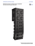
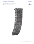
ASSEMBLY GUIDE M SERIES : QUICKFLY M1D RIGGING GRIDS AND ACCESSORIES This Assembly Guide provides instructions on how to safely assemble and use the MG-1D multipurpose grid, the MTG-1D top grid and the MUB-1D multipurpose U-bracket. Following are descriptions of major components and how they work together, and examples of common uses. 1. 2. 3. 4. GENERAL INFORMATION 3 Safety Statement Scope of this Manual Load Ratings and Specifications Regulatory Compliance Safety Responsibilities “Above the Hook” Inspection and Maintenance Replacement Parts Training Component Overview M1D Grid Cam Overview 3 3 3 3 4 4 4 4 5 6 MG-1D MULTIPURPOSE GRID 7 List of Contents Grid Dimensions MG-1D Grid in Forward Flown Configuration MG-1D Grid in Reversed Flown Configuration MG-1D Grid in Forward Ground Stacked Configuration MG-1D Grid in Reversed Ground Stacked Configuration Using the MG-1D Grid to Transition from M2D to M1D Arrays Using the MG-1D Grid to Transition from M2D to 3 UPA-2P Loudspeakers (40° Splay) Using the MG-1D Grid to Transition from M2D to a Single UPA-1P Loudspeaker Using the MG-1D Grid to Transition from M2D to 2 MSL-4 Loudspeakers (30° Splay) Using the MG-1D Grid to Fly M2D and M2D-Sub Loudspeakers 7 7 8 9 10 11 12 13 14 15 16 MTG-1D TOP GRID 17 List of Contents Grid Dimensions MTG-1D Top Grid in Forward Flown Configuration MTG-1D Top Grid in Reversed Flown Configuration 17 18 19 MUB-1D MULTIPURPOSE U-BRACKET 20 U-Bracket Dimensions Angle Settings Load Ratings MUB-1D Multipurpose U-Bracket in Floor- or Ceiling-Mounted Configuration MUB-1D Multipurpose U-Bracket in Flown Configuration 20 20 21 22 22 M1D Rigging Grids and Accessories 1. GENERAL INFORMATION SAFETY STATEMENT Please read this Statement carefully and in its entirety. It contains important information regarding safety issues, including guidelines for general safe use of rigging systems as well as advisories on government regulations and liability laws. SCOPE OF THIS MANUAL Although this manual contains much useful information on rigging in general, it does not claim to be a comprehensive resource on the subject. This manual assumes that the owners and/or users of a QuickFly system are knowledgeable and experienced in the areas of rigging and flying loudspeaker systems. MANY ISSUES OF CRUCIAL CONCERN, SUCH AS THE DETERMINATION OF APPROPRIATENESS AND CONDITION OF VENUE RIGGING POINTS, CANNOT BE ADDRESSED HERE. THEREFORE, THE USER MUST ASSUME ALL RESPONSIBILITY FOR THE APPROPRIATE USE OF QUICKFLY SYSTEMS IN ANY PARTICULAR LOCATION OR CIRCUMSTANCE. The suspension of large, heavy objects in public places is subject to numerous laws and regulations at the national/ federal, state/provincial, and local levels. This manual does not address the specifics of any such applicable laws and government regulations. This manual details procedures and practices consistent with those generally acknowledged as allowable and safe in the United States. However, the user must assume responsibility for making sure that use of any QuickFly system and its components in any particular circumstance or venue conforms to all applicable laws and regulations in force at the time. LOAD RATINGS AND SPECIFICATIONS Long-term safe operation is a central concern in the design and manufacture of any rigging/flying system. Meyer Sound has taken great care in material selection and component design. In all critical cases, load points are redundant, with a safety margin that allows one or more load points to fail while maintaining system integrity. After manufacture, all load-critical system components are individually inspected. All load ratings and other specifications given in this manual are the result of accepted engineering practice and careful testing. However, such specifications and ratings are subject to change. USERS SHOULD CHECK THE QUICKFLY SECTION OF THE MEYER SOUND WEBSITE AT http://www.meyersound.com OR CONTACT TECHNICAL SUPPORT AT REGULAR INTERVALS TO CHECK FOR UPDATED OR REVISED INFORMATION. REGULATORY COMPLIANCE The design and safe working load (SWL) ratings of the QuickFly system are intended to be in compliance with all known regulatory statutes currently applicable in the United States. Unless otherwise specified, all working loads are based on either a 5:1 or 7:1 safety factor. However, as noted above, there are wide variations internationally in the regulations and practices applying to suspension of sound systems in public places. Although regulations in the United States are generally among the most stringent, safety codes may be even stricter in a few localities (such as those highly prone to earthquakes). In addition, applicable safety codes are open to interpretation: Government officials in one location may have a stricter interpretation than another local official, even when operating under the same regulations and in the same legal jurisdiction. CONSEQUENTLY, USERS OF QUICKFLY RIGGING SYSTEMS SHOULD BE PREPARED TO TAKE ADDITIONAL SAFETY ASSURANCE MEASURES BEYOND THOSE OUTLINED IN THIS MANUAL. IN ALL CASES, IT IS THE RESPONSIBILITY OF THE USER TO MAKE CERTAIN THAT ANY MEYER SOUND LOUDSPEAKER SYSTEM IS SUSPENDED IN ACCORDANCE WITH ALL APPLICABLE NATIONAL/FEDERAL, STATE/PROVINCIAL, AND LOCAL REGULATIONS. Meyer Sound Laboratories Inc. www.meyersound.com T: +1 510 486.1166 F: +1 510 486.8356 PN: 05.115.001.01 B Page 3 of 24 M1D Rigging Grids and Accessories SAFETY RESPONSIBILITIES “ABOVE THE HOOK” In most touring applications of rigging systems, the touring sound provider is normally responsible for ensuring the safety of the suspension system only below the attachment point. The safety and suitability of the attachment point is generally seen as the responsibility of the venue owner or operator. However, this distinction (“above the hook” versus “below the hook”) can be open to interpretation. Touring system operators should double-check to make certain that attachment points are approved and suitably load rated, and that the points used are those identified as such by the venue owner or operator. AS AN EXTRA PRECAUTION, CAREFUL INSPECTION OF THE ATTACHMENT POINTS IS ADVISED BEFORE FLYING, PARTICULARLY IN OLDER VENUES OR THOSE HOSTING FREQUENT EVENTS USING LARGE SOUND AND LIGHTING SYSTEMS. In any case, Meyer Sound QuickFly systems are intended only for suspension from approved rigging points, each known to have ample SWL margins for the system components suspended below them. INSPECTION AND MAINTENANCE The Meyer Sound QuickFly systems are an assembly of mechanical devices, and are therefore subject to wear and tear over prolonged use, as well as damage from corrosive agents, extreme impact, or inappropriate use. BECAUSE OF THE SAFETY ISSUES INVOLVED, USERS MUST ADOPT AND ADHERE TO A SCHEDULE OF REGULAR INSPECTION AND MAINTENANCE. IN TOURING APPLICATIONS, KEY COMPONENTS MUST BE INSPECTED BEFORE EACH USE. Such inspection includes examination of all load-bearing components for any sign of undue wear, twisting, buckling, cracking, rusting, or other corrosion. In regard to rust and corrosion, the main components of a QuickFly system are either protected by an exterior coating or made from stainless steel, which is impervious to rust and resistant to most corrosive fluids. Nevertheless, normal use and shipping vibrations can wear through the protective coatings, and extremely corrosive fluids (such as battery acid) can cause severe damage with prolonged exposure even to protected parts. Particular attention should be given to screws, bolts, and other fasteners to make certain the fittings are tight and secure. Metal seams and welds should be examined for any sign of separation or deformation. Meyer Sound strongly recommends that written documentation be maintained on each QuickFly system, noting date of inspection, name of inspector, points of system checked, and any anomalies discovered. Annual Comprehensive Examination and Test Program In addition to routine checks on the road for touring systems, Meyer Sound also recommends a careful, comprehensive system examination and testing “at home” in the warehouse or other appropriate location at regular intervals. Such at home examinations and tests should occur at least once a year, and should include a careful inspection of each component under ideal lighting conditions, and then a final comprehensive check of the entire system after it has been flown. If any anomalies or defects are discovered that could possibly affect the safety or integrity of the system, affected parts or subsystems should be replaced in their entirety before that part of the system is flown again. REPLACEMENT PARTS Any component found to be defective, or any safety-related component you even suspect might be defective, should be replaced with the equivalent, approved part. Parts specific to a QuickFly system should be ordered directly from Meyer Sound. No attempt should be made to substitute what appears to be equivalent or “mostly the same” generic replacements. Some parts used in QuickFly systems are identical to those used in other rigging applications. To the best of our knowledge, most of these suppliers are reputable and their products are reliable. However, Meyer Sound has no way of assuring the quality of products made by these various suppliers. Therefore, Meyer Sound is not responsible for problems caused by components that were not supplied by Meyer Sound. TRAINING QuickFly systems are relatively straightforward and easy to use. However, they should only be used by persons trained in the use of loudspeaker rigging systems who have mastered key points of assembly, rigging and flying. Users should read this manual in its entirety before attempting to deploy any QuickFly system. You may make additional copies of this manual as necessary for in-house use; copies may not be made for any other purpose. Meyer Sound Laboratories Inc. www.meyersound.com T: +1 510 486.1166 F: +1 510 486.8356 PN: 05.115.001.01 B Page 4 of 24 M1D Rigging Grids and Accessories COMPONENT OVERVIEW MG-1D Multipurpose Grid The MG-1D multipurpose grid allows M1D ultra-compact curvilinear array loudspeakers and M1D-Sub ultra-compact subwoofers to be flown or ground stacked. An adjustable rear extension frame provides flexibility and keeps the point load equal. Up to 16 M1Ds (or the equivalent weight of M1D/ M1D-Subs) may be suspended from single or multiple rigging points of appropriate rating, with a safety factor of 7:1. The MG-1D also supports flying 7 M2Ds (or the equivalent weight of M2D/M2D-Sub loudspeakers) at a safety factor of 7:1, and provides a transition from the bottom of an M2D and/or M2D-Sub array to: an M1D/M1D-Sub array 1 UPA-1P compact wide coverage loudspeaker 3 UPA-2P compact narrow coverage loudspeakers 2 MSL-4 horn-loaded long-throw loudspeakers, or 2 DS-4P horn-loaded mid-bass loudspeakers MTG-1D Top Grid The MTG-1D top grid provides multiple hanging configurations for M1D and/or M1D-Sub arrays. MTG1D allows single- or multi-point support and bridles. An adjustable rear extension frame provides flexibility and keeps the point load equal. Up to 16 M1Ds (or the equivalent weight of M1D and M1D-Subs) may be suspended from single or multiple rigging points of appropriate rating, with a safety factor of 7:1. MUB-1D Mounting U-Bracket The MUB-1D mounting U-bracket supports multiple M1D loudspeakers depending on the mounting configuration. The MUB-1D is a simple yet versatile rigging option that can provide numerous tilt angles, and is ideal for front fill, under balcony, single unit or any small array applications. NOTE: For large M1D arrays with or without M1D-Subs it is recommended that you use the MTG-1D top grid or MG-1D multipurpose grid. Meyer Sound Laboratories Inc. www.meyersound.com T: +1 510 486.1166 F: +1 510 486.8356 PN: 05.115.001.01 B Page 5 of 24 M1D Rigging Grids and Accessories M1D GRID CAM OVERVIEW The M1D grid cams are used to connect an M1D/M1D-Sub to the MG-1D multipurpose grid or MTG-1D top grid. The holes in the M1D grid cams align with holes in the MRF-1D rigging frame and the MG-1D grid. Two quick release pins (QRPs) are provided per side that insert through the holes. A variety of tilt angles can be achieved through the selection of pin positions. In a flown array, positive angles are used for up tilt and negative angles are used for down tilt with respect to the adjacent element above. For ground stack array configurations, the angle is with respect to the adjacent element below. The angle of the loudspeaker in relation to the grid is calculated by adding together the numbers etched next to each hole. When an M1D is the first unit in the array, the M1D grid cam provides from -14° to +14° of tilt in 2-degree increments. If an M1D-Sub is used as the first unit, 0° to +14° of tilt is possible, again in 2-degree increments. Although flown configurations may not require the flexibility of the M1D grid cam, it should always be used as the first link between the grid and the array. In flown configurations, the up and down tilt can additionally be adjusted using chain motors, or differing lengths of steel or span set. In a ground supported situation, however, the M1D grid cam is the only way to tilt the array up or down in relation to the MG-1D grid. Grid Side Example 1 (Flown) Top grid cam pin position +2 Bottom grid cam pin position -4 Total angle -2° (down tilt) QRP locations Top grid cam pin position To M1D loudspeaker 0 Bottom grid cam pin position +8 Total angle +8° (up tilt) QRP locations Meyer Sound Laboratories Inc. www.meyersound.com To M1D loudspeaker To Grid Grid Side Example 2 To Grid T: +1 510 486.1166 F: +1 510 486.8356 To Grid To Grid PN: 05.115.001.01 B Page 6 of 24 M1D Rigging Grids and Accessories 2. MG-1D MULTIPURPOSE GRID The MG-1D multipurpose grid allows multiple M1D ultra-compact curvilinear array loudspeakers, M1D-Sub ultracompact subwoofers, M2D compact curvilinear array and M2D-Sub compact subwoofers to be flown, and provides ground support for M1D and M1D-Sub loudspeakers. The MG-1D grid can also serve as a transition grid. Refer to the overview on page 5 for possible configurations. There are pick-up points in the center of the grid, and three pick-up points on the extension frame. List of Contents: MG-1D Multipurpose Grid Kit (Part 40.115.100.01) List of Contents: MG-1D Multipurpose Grid Kit (Part #40.115.100.01) Qty Part Number Description 1 40.115.100.01 MG-1D Multipurpose Grid Assembly 2 61.115.112.01 M1D Grid Cam 10 134.020 5/16” x 1.25” Quick Release Pin (QRP) 6 124.074 Leveling Foot MG-1D Multipurpose Grid Dimensions ����� ��������� ����� ��������� ���� �������� ����� ��������� ���� ��������� ����� ��������� ����� ��������� ����� ��������� ���� �������� ���� �������� ���� ���� ��������� ��������� ����� ��������� ����� ��������� NOTE: To expand or retract the MG-1D grid extension frame, remove all four QRPs. Once the extension frame is extended to its outer position, reinstall the QRPs, securing the extension frame safely to the MG-1D grid. If you are working in conditions where weight is a factor, you have the option to reduce your overall load by 20 pounds (9.01 kg) by removing the extension frame completely. ����� ���������� ����� ��������� MG-1D Multipurpose Grid Weight: 93 lbs (42.18 kg) Meyer Sound Laboratories Inc. www.meyersound.com T: +1 510 486.1166 F: +1 510 486.8356 PN: 05.115.001.01 B Page 7 of 24 M1D Rigging Grids and Accessories MG-1D GRID IN FORWARD FLOWN CONFIGURATION “Forward Flown” dilineates that the MG-1D multipurpose grid is oriented with its integral sliding extension frame to the rear. This is the most common configuration for flying an M1D and/or M1D-Sub array. It provides from -14° to +14° of tilt in 2-degree increments between the grid and the first loudspeaker when using an M1D as the first element of the array. If more tilt is required, the grid may also be tilted up or down by using single or multiple rigging points. If further down tilt is needed, this can be achieved using the grid’s extension frame in the extended position. Install the M1D grid cam as shown into the MG-1D grid, with the grid side of the M1D grid cam facing the MG-1D grid. Secure all M1D grid cams with the quick release pins (QRPs), then install the M1D at the predetermined angle (see page 5 for more information on setting tilt angles). The M1D grid cam is only used in transition from the MG-1D multipurpose grid to the first M1D/M1D-Sub. After this is complete, use the M1D links with the QRPs to complete the rest of the array as shown. Maximum Load: 7:1 safety factor: Up to 16 M1Ds or the equivalent weight of M1Ds and/or M1DSubs or other products specified for use with this grid. (496 lbs, 225 kg) 5:1 safety factor: Up to 22 M1Ds or the equivalent weight of M1Ds and/or M1DSubs or other products specified for use with this grid. (682 lbs, 309.2 kg) CAUTION: When flying an array from the MG-1D multipurpose grid, it must always be supported by at least one pick-up hole from the main frame’s center bracket. The extension frame may be used as a secondary pick-up location for tilting the array or spreading the load between two points. WARNING: The leveling feet must always be detached from the MG-1D multipurpose grid before flying a system. Unscrew the entire assembly, including the threaded leg, and remove completely. NOTE: If the first element of the array is an M1D-Sub, the M1D grid cam needs to be reversed (grid side facing the Sub). In this case, up tilt from 0° to +14° increments is possible. Use M1D links to complete the rest of the array. Meyer Sound Laboratories Inc. www.meyersound.com T: +1 510 486.1166 F: +1 510 486.8356 PN: 05.115.001.01 B Page 8 of 24 M1D Rigging Grids and Accessories MG-1D GRID IN REVERSED FLOWN CONFIGURATION “Reversed Flown” dilineates that the MG-1D multipurpose grid is oriented with its integral sliding extension frame to the front. This configuration is used for applications that require the grid to be tilted more severely upward, causing the array’s center of gravity to move forward of the farthest forward pick-up hole on the grid’s center bracket. It provides from -14° to +14° of tilt in 2-degree increments between the grid and the first loudspeaker when using an M1D as the first element of the array. Reversing the MG-1D grid positions its extension frame in front of the array, providing a forward pick-up point. Further up tilt can be achieved using the extension frame in the extended position. Install the M1D grid cam as shown into the MG-1D grid. Please note that the grid side of the M1D grid cam faces the MG-1D grid. Secure all M1D grid cams with the quick release pins (QRPs). Then install the M1D at the predetermined angle. The M1D grid cam is only used in transition from the MG-1D multipurpose grid to the first M1D. After this is complete, use the M1D links with the QRPs to complete the rest of the array as shown. Maximum Load: 7:1 safety factor: Up to 16 M1Ds or the equivalent weight of M1Ds and/or M1D-Subs or other products specified for use with this grid. (496 lbs, 225 kg) 5:1 safety factor: Up to 22 M1Ds or the equivalent weight of M1Ds and/or M1D-Subs or other products specified for use with this grid. (682 lbs, 309.2 kg) CAUTION: When flying an array from the MG-1D grid, it must always be supported by at least one pick-up hole from the main frame’s center bracket. The extension frame may be used as a secondary pick-up location for tilting the array or spreading the load between two points. NOTE: If the first element of the array is an M1DSub, the M1D grid cam needs to be reversed (grid side facing the M1D-Sub). In this case, up tilt from 0° to +14° in 2-degree increments is possible. Use M1D links to complete the rest of the array. WARNING: The leveling feet must always be detached from the MG-1D multipurpose grid before flying a system. Unscrew the entire assembly, including the threaded leg, and remove completely. Meyer Sound Laboratories Inc. www.meyersound.com T: +1 510 486.1166 F: +1 510 486.8356 PN: 05.115.001.01 B Page 9 of 24 M1D Rigging Grids and Accessories MG-1D GRID IN FORWARD GROUND STACKED CONFIGURATION This configuration is used for ground stacking a predominantly up tilted M1D and/or M1D-Sub array. It provides from -14° to +14° of tilt in 2-degree increments between the MG-1D multipurpose grid and the first loudspeaker when using an M1D as the first element of the array. The grid’s extension frame (located to the rear of the array) can be deployed to provide a larger footprint towards the rear for improved stability. Install the M1D grid cam as shown into the MG-1D grid. Please note that the grid side of the M1D grid cam faces the MG-1D grid. Secure all cams with the quick release pins (QRPs), then install the M1D at the pre-determined angle. The M1D grid cam is only used in transition from the MG-1D grid to the first M1D/M1D-Sub. After this is complete, use the M1D links with the QRPs to complete the rest of your array as shown. CAUTION: When ground stacking an M1D/M1D-Sub array on an MG-1D multipurpose grid, always keep the center of gravity within the footprint of the leveling feet. For extra stability, the footprint can be enlarged by use of the extension frame. To further secure larger arrays, particularly in outdoor situations, use a tie down or extra weight on the grid, or a safety system on the array. NOTE: If the first element of the array is an M1D-Sub, the M1D grid cam needs be reversed (grid side facing the M1D-Sub). In this case, down tilt from 0° to -14° in 2-degree increments is possible. Use M1D links to complete the rest of the array. Meyer Sound Laboratories Inc. www.meyersound.com T: +1 510 486.1166 F: +1 510 486.8356 PN: 05.115.001.01 B Page 10 of 24 M1D Rigging Grids and Accessories MG-1D GRID IN REVERSED GROUND STACKED CONFIGURATION This configuration is used for ground stacking a predominantly down or forward tilted M1D and/or M1D-Sub array. It provides from -14° to +14° of tilt in 2-degree increments between the grid and the first loudspeaker when using an M1D as the first element of the array. For tall arrays with severe down or forward tilt, the grid’s extension frame can be deployed to provide a larger footprint towards the front for improved stability. Install the M1D grid cam as shown into the MG-1D multipurpose grid. Please note that the grid side of the M1D grid cam faces the MG-1D. Secure all M1D grid cams with the quick release pins (QRPs). Then install the M1D at the pre-determined angle. The M1D grid cam is only used in transition from the MG-1D grid to the first M1D. After this is complete, use the M1D links with the QRPs to complete the rest of the array as shown. NOTE: If the first element of the array is an M1DSub, the M1D grid cam needs to be reversed (grid side facing the M1D-Sub). In this case, down tilt from 0° to -14° in 2-degree increments is possible. Use M1D links to complete the rest of the array. CAUTION: When ground stacking an M1D/M1D-Sub array on an MG-1D grid, always keep the center of gravity within the footprint of the leveling feet. For extra stability, the footprint can be enlarged by use of the extension frame. To further secure larger arrays, particularly in outdoor situations, use a tie down or weight on the grid or a safety system on the array. Meyer Sound Laboratories Inc. www.meyersound.com T: +1 510 486.1166 F: +1 510 486.8356 PN: 05.115.001.01 B Page 11 of 24 M1D Rigging Grids and Accessories USING THE MG-1D GRID TO TRANSITION FROM M2D TO M1D ARRAYS This configuration is used for applications that require the MG-1D grid to be used to transition from an M2D and M2D-Sub array to a M1D and/or M1D-Sub array. It provides from 0° to -7° of tilt in 1-degree increments between the M2D and the grid, and -14° to +14° of tilt in 2-degree increments between the MG-1D multipurpose grid and the first loudspeaker when using an M1D as the first element of the array. This figure below shows how the MG-1D grid can be configured to provide a transition from an M2D to an M1D system. Note the orientation of the grid. Install the M2D’s CamLink and front link into the cam and link positions on the MG-1D grid as shown. Securely fasten using M2D 5/16" quick release pins, then attach the M1Ds and angle as desired. CAUTION: When flying an MG-1D grid and M1D array beneath an M2D array, include the weight of the grid and the weight of the M1D array in your total weight calculations. Do not exceed the weight rating of the primary supporting grid. NOTE: If the first element of the array is an M1D-Sub, the M1D grid cam needs to be reversed (grid side facing the M1D-Sub). In this case, up tilt from 0° to +14° in 2-degree increments is possible. Use M1D links to complete the rest of the array. WARNING: The leveling feet must always be detached from the MG-1D grid before flying a system. Unscrew the entire assembly, including the threaded leg, and remove completely. Meyer Sound Laboratories Inc. www.meyersound.com T: +1 510 486.1166 F: +1 510 486.8356 PN: 05.115.001.01 B Page 12 of 24 M1D Rigging Grids and Accessories USING THE MG-1D GRID TO TRANSITION FROM M2D TO 3 UPA-2P LOUDSPEAKERS (40° SPLAY) This configuration provides 0° to 7° of down tilt in 1-degree increments for a downfill of UPA-2P compact narrow coverage loudspeakers when transitioning from an M2D array. A total of 110 degrees of horizontal coverage is provided by the UPA-2P array. The UPA-2Ps can also be flown independently with the MG-1D grid from a single pickup point on the frame’s center bracket. To assemble this configuration, lift the D-Rings on the UPA-2Ps and guide them into each hole marked with a triangle on the MG-1D grid. Fasten by fully inserting the quick release pins (QRPs) into the appropriate holes in the grid while securing the D-Rings. The MG-1D grid can then be attached to the M2D system using the M2D CamLinks, M2D front links and M2D 5/16” QRPs. Maximum Load: Triangle-marked UPA-2P pick-up points. 7:1 safety factor: 2 rows of (3) UPA-2Ps 462 lbs (209.5 kg) CAUTION: When flying an MG-1D grid and UPA-2P array beneath an M2D array, include the weight of the grid and the weight of the UPA-2P array in your total weight calculations. Do not exceed the weight rating of the primary supporting grid. CAUTION: When using an MG-1D multipurpose grid as a top grid to fly a UPA2P array, it must always be supported by at least one pick-up hole from the main frame’s center bracket. The extension frame may be used as a secondary pick-up location for tilting the array or spreading the load between two points. WARNING: The leveling feet must always be detached from the MG-1D grid before flying a system. Unscrew the entire assembly, including the threaded leg, and remove completely. Meyer Sound Laboratories Inc. www.meyersound.com T: +1 510 486.1166 F: +1 510 486.8356 PN: 05.115.001.01 B Page 13 of 24 M1D Rigging Grids and Accessories USING THE MG-1D GRID TO TRANSITION FROM M2D TO A SINGLE UPA-1P LOUDSPEAKER When transitioning from an M2D array, this configuration provides 0° to 7° of down tilt in 1° increments for a downfill comprised of a single UPA-1P compact wide coverage loudspeaker. The UPA-1P provides a total of 100° of horizontal coverage. The UPA-1P can also be flown independently with the MG-1D grid from a single pick-up point on the frame’s center bracket. To assemble this configuration, lift the D-Rings on the UPA-1P and guide them into each hole marked with a triangle on the MG-1D grid. Fasten by fully inserting the quick release pins (QRPs) into the appropriate holes in the grid while securing the D-Rings. The MG-1D grid can then be attached to the M2D system using the M2D CamLinks, M2D front links and M2D 5/16” QRPs. Maximum Load: Triangle-marked UPA pick-up points. 7:1 safety factor: 2 rows of (1) UPA-1Ps 154 lbs (70 kg) CAUTION: When flying an MG-1D grid and a UPA-1P beneath an M2D array, include the weight of the grid and the weight of the UPA-1P in your total weight calculations. Do not exceed the weight rating of the primary supporting grid. CAUTION: When using the MG-1D grid as a top grid to fly a UPA-1P, it must always be supported by at least one pick-up hole from the main frame’s center bracket. The extension frame may be used as a secondary pick-up location for tilting the array or spreading the load between two points. WARNING: The leveling feet must always be detached from the MG-1D grid before flying a system. Unscrew the entire assembly, including the threaded leg, and remove completely. Meyer Sound Laboratories Inc. www.meyersound.com T: +1 510 486.1166 F: +1 510 486.8356 PN: 05.115.001.01 B Page 14 of 24 M1D Rigging Grids and Accessories USING THE MG-1D GRID TO TRANSITION FROM M2D TO 2 MSL-4 LOUDSPEAKERS (3O° SPLAY) This configuration allows a pair of MSL-4 horn-loaded long throw loudspeakers to be flown at a 30-degree splay when transitioning from an M2D and M2D-Sub array. The MG-1D grid provides from 0° to -7° of tilt in 1-degree increments between the M2D array and the grid. A total of 65 degrees of horizontal coverage is provided by the MSL-4s. The MSL-4s can also be flown independently with the MG-1D grid from a single pick-up point on the frame’s center bracket. Other Meyer Sound loudspeakers with the same footprint as the MSL-4 (DF-4 and DS-4P) can be used in this configuration. Configure the MG-1D grid to allow the attachment of MSL-4s by pulling out the extension frame to the second pin position. Lift the D-Rings on the MSL-4s and guide them into each hole marked with a square on the MG-1D grid. Fasten by fully inserting the quick release pins (QRPs) (C) into the appropriate holes in the grid while securing the D-Rings. The MG1D grid can then be attached to the M2D system by using the M2D CamLinks, M2D front links and M2D 5/16" QRPs. Maximum Load: Square-marked MSL-4 pick-up points. 5:1 safety factor: 2 rows of (2) MSL-4s 720 lbs (326.5 kg) CAUTION: When flying an MG-1D multipurpose grid and MSL-4s beneath an M2D array, include the weight of the grid and the weight of the MSL-4s in your total weight calculations. Do not exceed the weight rating of the primary support grid. CAUTION: When using the MG-1D grid as a top grid to fly MSL-4s, it must always be supported by at least one pick-up hole from the main frame’s center bracket. The extension frame may be used as a secondary pick-up location for tilting the array or spreading the load between two points. WARNING: The leveling feet must always be detached from the MG-1D grid before flying a system. Unscrew the entire assembly, including the threaded leg, and remove completely. Meyer Sound Laboratories Inc. www.meyersound.com T: +1 510 486.1166 F: +1 510 486.8356 PN: 05.115.001.01 B Page 15 of 24 M1D Rigging Grids and Accessories USING THE MG-1D GRID TO FLY M2D AND M2D-SUB LOUDSPEAKERS For smaller M2D arrays, the MG-1D multipurpose grid can be used as the primary rigging frame. If greater flexibility with up or down tilt of the entire array is required, the MG-2D multipurpose grid should be used. Install the M2D CamLink (A) as shown between the MG-1D multipurpose grid (C) and the first cabinet. Install the M2D FrontLinks (B) as shown, and secure all with three QRPs. Note that MG-1D grid is flipped 180 degrees from its normal position (leveling feet extenders are pointing downward). NOTE: For large M2D arrays with or without M2D-Subs, use the MG-2D multipurpose grid. Maximum Load: CAUTION: Never use the MG-1D multipurpose grid for ground-stacking M2D or M2D-Subs. 7:1 safety factor: Up to 7 M2Ds or the equivalent weight of M2Ds and/ or M2D-Subs or other products specified for use with this grid. 5:1 safety factor: Up to 10 M2Ds or the equivalent weight of M2Ds and/or M2D-Subs or other products specified for use with this grid. CAUTION: When flying an array from the MG-1D multipurpose grid, it must always be supported only by the pick-up holes from the main frame’s center bracket. C A B CAUTION: Do not use the MG-1D extension frame with M2D and/or M2D-Sub cabinets. The MG-1D extension frame is rated only for use with M1D and M1D-Sub loudspeakers. CAUTION: The leveling feet must always be detached from the MG-1D multipurpose grid before flying a system. Unscrew the entire assembly, including the threaded leg, and remove completely. Meyer Sound Laboratories Inc. www.meyersound.com T: +1 510 486.1166 F: +1 510 486.8356 PN: 05.115.001.01 B Page 16 of 24 M1D Rigging Grids and Accessories 3. MTG-1D TOP GRID The MTG-1D top grid is a very simple, straightforward solution for rigging M1Ds. The MTG-1D grid allows multiple M1D ultra-compact curvilinear array loudspeakers and/or M1D-Sub ultra-compact subwoofers to be flown in several configurations. There are pick-up points in the center of the grid, and three pick-up points on the grid’s extension frame. List of Contents: MG-1D Multipurpose Grid Kit (Part 40.115.100.01) List of Contents: MTG-1D Top Grid Kit (Part #40.115.110.01) Qty Part Number Description 1 40.115.110.01 MTG-1D Top Grid Assembly 2 61.115.112.01 M1D Grid Cam 10 134.020 5/16” x 1.25” Quick Release Pin (QRP) MTG-1D Top Grid Dimensions ����� ��������� ����� ��������� ���� �������� ���� �������� ����� ��������� ���� �������� ���� �������� ����� ��������� NOTE: To expand the MTG-1D grid extension frame, remove all four QRPs. Once the frame is in its extended position, reinstall the QRPs, securing the extension frame safely to the MTG-1D grid. If you are working in conditions where weight is a factor, you have the option to reduce your overall load by 13 pounds ����� (5.9 kg) by removing the extension frame ��������� completely. ���� �������� ����� ��������� ���� �������� ����� ��������� ����� ��������� MTG-1D Top Grid Weight: 51 lbs (23.13 kg) Meyer Sound Laboratories Inc. www.meyersound.com T: +1 510 486.1166 F: +1 510 486.8356 PN: 05.115.001.01 B Page 17 of 24 M1D Rigging Grids and Accessories MTG-1D TOP GRID IN FORWARD FLOWN CONFIGURATION “Forward Flown” dilineates that the MTG-1D grid is oriented with its sliding extension frame to the rear. This is the most common configuration for flying an M1D/M1D-Sub array. It provides from -14° to +14° of tilt in 2-degree increments between the grid and the first loudspeaker when using an M1D as the first element of the array. If more tilt is required, the grid may also be tilted up or down by using single or multiple rigging points. If further down tilt is needed, this can be achieved using the grid’s extension frame in the extended position. Install the M1D grid cam as shown into the MTG-1D grid, with the grid side of the M1D grid cam facing the MTG-1D grid. Secure all M1D grid cams with the quick release pins (QRPs), then install the M1D at the predetermined angle. The M1D grid cam is only used in transition from the MTG-1D grid to the first M1D/M1D-Sub. After this is complete, use the M1D links with the QRPs to complete the rest of the array as shown. Maximum Load: 7:1 safety factor: Up to 16 M1Ds or the equivalent weight of M1Ds and/or M1D-Subs. (496 lbs, 225 kg) 5:1 safety factor: Up to 22 M1Ds or the equivalent weight of M1Ds and/or M1D-Subs. (682 lbs, 309.2 kg) CAUTION: When flying an array from the MTG-1D grid, it must always be supported by at least one pick-up hole from the main frame’s center bracket. The extension frame may be used as a secondary pick-up location for tilting the array or spreading the load between two points. NOTE: If the first element of the array is an M1D-Sub, the M1D grid cam needs to be reversed (grid side facing the M1D-Sub). In this case, up tilt from 0° to +14° in 2-degree increments is possible. Use M1D links to complete the rest of the array. Meyer Sound Laboratories Inc. www.meyersound.com T: +1 510 486.1166 F: +1 510 486.8356 PN: 05.115.001.01 B Page 18 of 24 M1D Rigging Grids and Accessories MTG-1D TOP GRID IN REVERSED FLOWN CONFIGURATION “Reversed Flown” dilineates that the MTG-1D top grid is oriented with its sliding extension frame to the front. This configuration is used for applications that require the grid to be tilted more severely upward, causing the array’s center of gravity to move forward of the farthest forward pick-up hole on the grid’s center bracket. It provides from -14° to +14° of tilt in 2-degree increments between the grid and the first loudspeaker when using an M1D as the first element of the array. Reversing the MTG-1D grid positions the grid extension frame in front of the array, providing a forward pick-up point. Further up tilt can be achieved using the grid’s extension frame in the extended position. Install the M1D grid cam as shown into the MTG-1D top grid. Please note that the grid side of the M1D grid cam faces the MTG-1D grid. Secure all M1D grid cams with the quick release pins (QRPs). Then install the M1D at the predetermined angle. The M1D grid cam is only used in transition from the MTG-1D grid to the first M1D/M1D-Sub. After this is complete, use the M1D links with the QRPs to complete the rest of the array as shown. Maximum Load: 7:1 safety factor: Up to 16 M1Ds or the equivalent weight of M1Ds and/or M1D-Subs. (496 lbs, 225 kg) 5:1 safety factor: Up to 22 M1Ds or the equivalent weight of M1Ds and/or M1D-Subs. (682 lbs, 309.2 kg) CAUTION: When flying an array from the MTG-1D grid, it must always be supported by at least one pick-up hole from the main frame’s center bracket. The extension frame may be used as a secondary pick-up location for tilting the array or spreading the load between two points. NOTE: If the first element of the array is an M1D-Sub, the M1D grid cam needs to be reversed (grid side facing the M1D-Sub). In this case, up tilt from 0° to +14° in 2-degree increments is possible. Use M1D links to complete the rest of the array. Meyer Sound Laboratories Inc. www.meyersound.com T: +1 510 486.1166 F: +1 510 486.8356 PN: 05.115.001.01 B Page 19 of 24 M1D Rigging Grids and Accessories 4. MUB-1D MULTIPURPOSE U-BRACKET The MUB-1D multipurpose U-bracket is mainly designed to support and aim a single M1D ultra-compact curvilinear array loudspeaker in a floor or ceiling mounted configuration. However, it is robust and versatile enough for flying small arrays of M1D loudspeakers. Multiple mounting holes provide maximum flexibility. The MUB-1D U-bracket does not have the strength or functionality of a rigging grid and therefore it is NOT recommended for the following applications: - If the array’s length and the angles between the cabinets force its center of gravity to fall outside the footprint of the MUB-1D. - If the array includes M1D-Subs. - If the array requires up or down tilt using chain motors. - If the array exceeds the load rating of the MUB-1D. For these and other flown applications that require a rigging grid, the MTG-1D or the MG-1D should be used. For ground stacked arrays that require a support grid, or when a transition from an M2D and M2D-Sub array to a M1D array is needed, the MG-1D grid should be used. MUB-1D Multipurpose U-Bracket Dimensions: ������������ � ��������� �������������� ������������� � ��������� ������������� ������������� �������������� �������������� ������������� ������������ ������������ ������������ �������������� ������������� MUB-1D Multipurpose U-Bracket Weight: 7 lbs (3.18 kg) ANGLE SETTING A number of holes are provided on each end of the MUB-1D multipurpose U-bracket to facilitate angle setting. The holes align with those in the MRF-1D rigging frame on the M1D. Two quick release pins — provided with the M1D loudspeakers — per side are used to mount the M1D to the MUB-1D U-bracket. MUB-1D Multipurpose U-Bracket QRP Positions A variety of tilt angles are available through the selection of pin positions. The diagram below shows the angles that can be achieved with relation to the MUB-1D’s mounting plane. In ceiling-mounted or flown arrays, positive angles are used for up tilt and negative angles are used for down tilt. For floor mounted configurations, positive angles are used for down tilt. The MUB-1D U-bracket provides from +10° to -12° of tilt in 2-degree increments. Meyer Sound Laboratories Inc. www.meyersound.com T: +1 510 486.1166 F: +1 510 486.8356 PN: 05.115.001.01 B Page 20 of 24 M1D Rigging Grids and Accessories LOAD RATINGS Multiple holes are provided in the top surface of the MUB-1D U-bracket that accommodate a variety of hardware that can be used to suspend the device or secure it to a surface. Please note that each of the MUB-1D U-bracket’s mounting holes or sets of holes have individual load ratings. These are shown below. WARNING: When flying an array from the MUB-1D U-bracket, it must always be supported by pick-up holes whose ratings meet or exceed the weight of the array. Maximum Load Ratings: Outer 1/2” Holes Two Outer 1/2” Holes: 7:1 safety factor: Up to 10 M1Ds (320 lbs, 145 kg) 5:1 safety factor: Up to 14 M1Ds (448 lbs, 203 kg) NOTE: Load evenly distributed on the two points. Center 1/2” Hole One Center 1/2” Hole: 7:1 safety factor: Not rated 5:1 safety factor: 1 M1D (31 lbs, 14 kg) Four 1/4” Holes: 7:1 safety factor: Up to 3 M1Ds (96 lbs, 44 kg) 1/4” Holes 5:1 safety factor: Up to 4 M1Ds (130 lbs, 59 kg) NOTE: Load evenly distributed on all four points. WARNING: Always use mounting and rigging hardware that has been rated to meet or exceed the weight of the loudspeakers being hung. Meyer Sound Laboratories Inc. www.meyersound.com T: +1 510 486.1166 F: +1 510 486.8356 PN: 05.115.001.01 B Page 21 of 24 M1D Rigging Grids and Accessories MUB-1D MULTIPURPOSE U-BRACKET IN FLOOR- OR CEILING-MOUNTED CONFIGURATION In this configuration the MUB-1D U-bracket is used to mount and aim a single M1D on a floor, ceiling or other flat surface. It provides from +10° to -12° of tilt in 2-degree increments between the MUB-1D U-bracket’s mounting plane and the M1D loudspeaker. For safety reasons, it is not recommended to use more than one M1D in a ceiling-mount configuration. First install the MUB-1D multipurpose U-bracket on the floor, ceiling or other flat surface. Make sure to use mounting hardware that has been rated to meet or exceed the weight being hung and is appropriate for the construction of the mounting surface. Install the M1D loudspeaker into the MUB-1D U-bracket and secure the M1D with the quick release pins (QRPs) at the predetermined angle (see page 20 for more information on setting tilt angles). WARNING: Always use mounting hardware that is appropriate for the construction of the surface where the MUB-1D U-bracket will be installed. WARNING: Always use mounting and rigging hardware that has been rated to meet or exceed the weight being hung. MUB-1D MULTIPURPOSE U-BRACKET IN FLOWN CONFIGURATION In flown configurations, the MUB-1D U-bracket provides from +12° to -10° of tilt in 2-degree increments between the MUB-1D and the first M1D loudspeaker. Install the MUB-1D as shown onto the first M1D of the array and secure the M1D with the quick release pins at the predetermined angle (see page 20 for more information on setting tilt angles). The MUB-1D U-bracket is only attached directly to the first M1D loudspeaker in the array. Use the M1D links with the QRPs to complete the rest of the array as shown. WARNING: When flying an array from the MUB-1D U-bracket, it must always be supported by the pick-up holes whose load ratings meet or exceed the weight of the array. See page 21 for more information on Maximum Load Ratings. WARNING: Always use mounting and rigging hardware that has been rated to meet or exceed the weight being hung. Meyer Sound Laboratories Inc. www.meyersound.com T: +1 510 486.1166 F: +1 510 486.8356 PN: 05.115.001.01 B Page 22 of 24 Meyer Sound Laboratories Inc. 2832 San Pablo Avenue Berkeley, CA 94702 www.meyersound.com T: +1 510 486.1166 F: +1 510 486.8356 © 2004 Meyer Sound Laboratories Inc. PN: 05.115.001.01 B