1
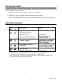
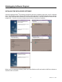
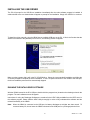
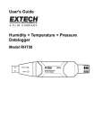
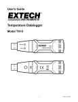
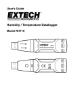
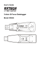
User's Guide 3-Axis G-Force Datalogger Model VB300 Introduction Congratulations on your purchase of the VB300 G-Force Datalogger. The Model VB300 can measure and record shock and vibration (acceleration) readings over its ± 18g measurement range. This device will record 3-axis g-force and related peaks to provide a history of shock and vibration conditions. The real time clock provides time stamps for all data. The user can easily configure the logging rate, high/low alarm and start-mode, and download the stored data by plugging the VB300 into a PC's USB port and running the supplied PC software. Measurement data can be plotted, printed and exported for use with other applications such as word processors and spreadsheets. The data logger is supplied with a long-life 1000 hour lithium battery. The VB300 memory uses a 4MB Flash device that can hold 85,764 peak acceleration samples and 210 freefall samples. This meter is shipped fully tested and calibrated and, with proper use, will provide years of reliable service. Features Records 3-axis g force shock and vibration Built-in accelerometer Measures static and dynamic acceleration Real time operation (time stamped data) Normal and Motion detection mode Real time FFT frequency analysis Manual and Automatic datalogger start modes Selectable data sampling rate Status Indication via Red and Green LEDs USB Interface for Set-up and Data Download User-Programmable motion thresholds Long battery life - 1000 hours 2 VB300 V1.1 11/10 Description Meter Description 1. USB connector 2. RECORD LED 3. ALARM LED 4. Datalogger Start / Stop Button 5. Axis reference diagram Note: Battery compartment access screws (2) located on rear of unit. Refer to the battery installation section for further details. Pedestal Mount Description 1. Mounting screw holes 2. Swivel latch 3. Swivel latch lock 4. Mounting magnets FRONT VIEW 3 REAR VIEW VB300 V1.1 11/10 Mounting the VB300 The VB300 fits securely in the supplied mounting pedestal. Unscrew the pedestal latch and snap the VB300 into the pedestal. Secure the latch and follow one of the mounting methods below. There are three mounting methods for affixing the pedestal to the area under test: 1. Magnetically: Powerful magnets are built into the rear of the pedestal 2. Adhesive: Use glue (not supplied) to affix the pedestal to the area under test 3. Screws: Three mounting holes are provided on the pedestal for screw mounting (screws not supplied) LED Status Indication LED Record Description Action Alarm LEDs not flashing -No logging in process -No battery found - Install battery -Battery completely discharged - Replace the battery and download the data Press and hold the datalogger Start/Stop button on the VB300 until the red LED flashes four times to stop logging If the unit is datalogging it will stop automatically. The Data will NOT be lost. Replace battery Green single flash every 10 sec. * -Logging, no alarm** Red single flash every 30 sec. * -Low Battery Red and Green alternating flashing every 60 seconds; -Datalogger memory is full * ** † -Download data To save power, the VB300’s LED flashing cycle can be changed to via the supplied software. To save power, alarm LEDs for temperature can be disabled via the supplied software. When the battery is low, all operations will be disabled automatically. NOTE: Logging automatically stops when the battery weakens (logged data will be retained). 4 VB300 V1.1 11/10 Datalogging Software Program INSTALLING THE DATALOGGER SOFTWARE Install the supplied WindowsTM PC Datalogger Software by placing the supplied program disk in the PC’s CD-ROM drive. If the installation program does not automatically open and provide on-screen prompts (as shown in diagram below), open and browse the CD-ROM drive, then find and double-click on the SETUP.EXE file included on the program disk. Follow the on-screen prompts as shown below to complete the installation. Before running the datalogger software, please connect the VB300 to the PC and install the USB Driver software as described in the next section. 5 VB300 V1.1 11/10 INSTALLING THE USB DRIVER The PC will prompt for the USB Driver installation immediately after the main software program is installed. A window similar to the one shown below will appear to prompt for the installation. Simply click INSTALL to continue. To install the driver manually, plug the VB300 into an available USB port on the PC. If this is the first time that the VB300 is connected to the particular port on the PC, the following screen will appear: Make sure the program disk is still in the PC CD-ROM drive. Select the ‘recommended’ installation and follow the on-screen prompts to complete the driver installation. If this is a repeat connection of the VB300 to the USB port, the driver installation process will be automatically skipped. RUNNING THE DATALOGGER SOFTWARE With the VB300 inserted in the PC’s USB port, double-click the program icon (located on the desktop) to launch the program. The main software screen will appear. Instructions for using the Datalogger Software are contained in the HELP Utility available from the HELP menu in the software program. Please read the HELP Utility thoroughly in order to fully understand the software and the related functionality of the VB300. Note: When the VB300 is connected to the USB port, its battery discharges at a higher rate than normal. To conserve battery life, do not leave the VB300 connected to the USB port for a prolonged period of time. 6 VB300 V1.1 11/10 Basic Datalogger Operation This section covers only the starting and stopping of the Datalogger’s recording functions. All other information is provided in the HELP utility within the software program. 1. Configure the Datalogger’s sample rate, motion detection threshold, record mode, LED flash cycle and more using the supplied software program. Refer to the instructions included in the software program’s HELP utility to configure the datalogger and to otherwise use the software. 2. If AUTO start is selected in the software, the datalogger will begin logging data the moment the software window is closed. If MANUAL is selected, press and hold the datalogger start/stop button until the green LED flashes; the datalogger LED flashes periodically (flash interval time selectable in software) indicating that the datalogger is recording. 3. To stop datalogging, press and hold the start/stop button while the unit is datalogging. The red LED will quickly flash indicating that datalogging has stopped. Refer to the LED status table earlier in this manual for interpreting the LED flash information. 4. Refer to the software HELP utility for transferring the data from the logger to the PC. 1g OFFSET The axis (or combination of axis) parallel to the earth surface will indicate the 1g force related to gravitational force. 5g 4g 3g 2g 1g 0g -1g X Y Z 7 VB300 V1.1 11/10 Specifications Acceleration Range: ± 18g Resolution: 0.00625g Accuracy ± 0.5g Frequency Range 0 to 60Hz Datalog Memory 4MB Flash stores 85,764 peak acceleration records Logging rate Selectable sampling interval: From 50ms up to 24 hours Data format Time stamped peak acceleration and freefall; Average and Peak Vector sums Computer PC interface USB Hardware requirements 8MB RAM; 2MB Hard Drive space for software program; USB jack System requirements WindowsTM XP, VISTA, WindowsTM 7 (32 and 64 bit) Operating temperature 32 to 104oF (0 to 40oC) Storage temperature 0 to 140oF (-10 to 60oC) Battery type 3.6V Lithium (1/2 AA) Power consumption 1mA (typical, while recording); < 15µA while idling Battery life 1000 hours approx. Dimensions/Weight 3.7 x 1.1 x 0.8” (95 x 28 x 21mm) / 6oz (172g) 8 VB300 V1.1 11/10 Battery Replacement The VB300 does not lose its stored readings when the battery expires or when the battery is replaced. The data logging process will however be stopped and cannot be re-started until the battery has been replaced and the logged data has been downloaded to PC. The battery life is rated for approx. 1000 hours. If in doubt, replace the battery before logging critical data. Use only 3.6V lithium batteries. Before replacing the battery, remove the datalogger from the PC. Note: When the VB300 is connected to the USB port, its battery discharges at a higher rate than normal. To conserve battery life, do not leave the VB300 connected to the USB port for a prolonged period of time. 1. Remove the two Phillips screws identified with the two smaller arrows in the diagram below. 2. Slide the battery compartment cover in the direction of the larger arrow. 3. Replace the battery with one of the same type (3.6V lithium, ½ AA). 4. Close the battery compartment and tighten with the two screws. WARNING: Handle lithium batteries carefully, observe warnings on battery casing. Dispose of in accordance with local regulations. Warranty EXTECH INSTRUMENTS CORPORATION (A FLIR COMPANY) warrants this instrument to be free of defects in parts and workmanship for one year from date of shipment (a six month limited warranty applies to sensors and cables). If it should become necessary to return the instrument for service during or beyond the warranty period, contact the Customer Service Department at (781) 890-7440 ext. 210 for authorization or visit our website www.extech.com for contact information. A Return Authorization (RA) number must be issued before any product is returned to Extech. The sender is responsible for shipping charges, freight, insurance and proper packaging to prevent damage in transit. This warranty does not apply to defects resulting from action of the user such as misuse, improper wiring, operation outside of specification, improper maintenance or repair, or unauthorized modification. Extech specifically disclaims any implied warranties or merchantability or fitness for a specific purpose and will not be liable for any direct, indirect, incidental or consequential damages. Extech's total liability is limited to repair or replacement of the product. The warranty set forth above is inclusive and no other warranty, whether written or oral, is expressed or implied. Support line (781) 890-7440 Technical support: Extension 200; E-mail: [email protected] Repair & Returns: Extension 210; E-mail: [email protected] Product specifications subject to change without notice For the latest version of this User Guide, Software updates, and other up-to-the-minute product information, visit our website: www.extech.com Extech Instruments Corporation, 285 Bear Hill Road, Waltham, MA 02451 ISO9001 Certified Copyright © 2010 Extech Instruments Corporation (a FLIR company) All rights reserved including the right of reproduction in whole or in part in any form. 9 VB300 V1.1 11/10