1
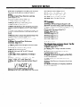
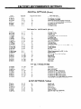
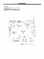
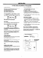
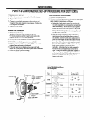
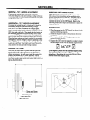
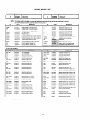
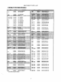
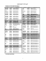
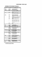
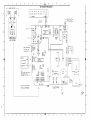
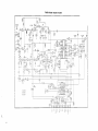
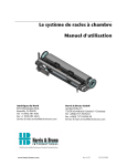
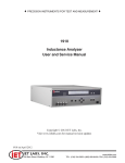
SERVICE
1 NTSC
]
27CX31 B 511
27CX31 B 521
MANUAL
1 GXCHASSIS
1
WC:
CAUTION:
CLU-418U2
CLU-411 ou
Before servicing this chassis, it is important that the service technician read
the “Safety Precautions”
and “Product Safety Notices” in this Service Manual.
This television receiver will display television
Closed Captioning (pi
) or ( I))
in accordance
with paragraph 15.119 of the FCC rules)
TABLE OF CONTENTS
1
Interconnect
Service Menu ................
2
Main Module Schematics
Factory Settings
4
Main Module S.M.D. Layout
5
Main Module Component
7
PIP Module Schematic
8
Jack Pack Schematic
............
28
10
Keyboard Schematic
............
29
13-l 8
Remote Schematic
Introduction
Servicing
.................
..............
..................
IF and Audio Alignment
Purity & Convergence
Remote Control
Component
..........
Procedure
..............
Parts List
...........
......
Diagram
Tuner Schematic
SPECIFICATIONS
AND PARTS ARE SUBJECT
............
19
..........
20
........
Layout
......
...........
27
31
..............
TO CHANGE FOR IMPROVEMENT
HHEA - MANUFACTURING
26
30
.............
SOLID STATE COLOR TELEVISION
JULY 1997
25
DIVISION
PRODUCT SAFETY SERVICING GUIDELINES FOR AUDIO-VIDEO
CAUTION:
Do not attempt to modify this product in any way. Never
perform
customized
installations
without
manufacturer’s
approval.
Unauthorized
modifications
will not only void the warranty, but may Iead to
your being liable for any resulting property damage or user injury.
Service work should be performed only after you are thoroughly familiar with
all of the following
safety checks and servicing
guidelines. To do otherwise
increases the risk of potential hazards and injury to the user.
While servicing,
use an isolation transformer
for protection
from AC line
shock.
After the original
following:
service
SAFETY
CHECKS
problem has been corrected,
make a check
of the
FIRE AND SHOCK
HAZARD
1. Be sure that all components
are positioned
to avoid a possibility of
adjacent component
shorts. This is especially important on modules
transported
to and from the repair shop.
2. Never release a repair unless all protective
devices such as insulators,
harriers, covers, shields, strain reliefs, power supply cords, and other
hardware have been reinstalled per the original design. Be sure that the
safety purpose of the polarized line plug has not been defeated.
3. Soldering must be inspected to discover possible cold solder joints,
solder splashes, or sharp solder points. Be certain to remove all loose
foreign particles.
4. Check for physical evidence of damage or deterioration
to parts and
components,
for frayed leads or damaged insulation (including the AC
cord), and replace if necessary. Follow the original layout, lead length,
and dress.
5. No lead or component
should touch a receiving
1 watt or more. Lead tension around protruding
avoided.
tube or a resistor rated at
metal surfaces must be
6. All critical components
such as fuses, flameproof
resistors, capacitors,
etc. must be replaced with exact factory types. Do not use replacement
components
other than those specified or make unauthorized
circuit
modifications.
I.
After reassembly
of the set, always perform an AC leakage test on all
exposed metallic parts of the cabinet (the channel selector knobs,
antenna terminals, handle and screws) to be sure the set is safe to operate
without danger of electrical shock. DO NOT USE A LINE ISOLATION
TRANSFORMER
DURING
THIS TEST. Use an AC voltmeter having
5000 ohms per volt or more sensitivity
in the following manner: Connect
a 1500 ohm, 10 watt resistor, paralleled by a .15 mfd 15OV AC type
capacitor between a known good earth ground (water pipe, conduit, etc.)
and the exposed metallic parts, one at a time. Measure the AC voltage
across the combination
of 1500 ohm resistor and .15 mfd capacitor.
Reverse the AC plug (if non-polarized)
and repeat AC voltage
measurements
for each exposed metallic part. Voltage measured must
not exceed 0.75 volts RMS. This corresponds
to 0.5 milliamp AC. Any
value exceeding this limit constitutes
a potential shock hazard and must
he corrected immediately.
A.C. Voltmeter
f,
I
PRODUCTS
X-RADIATION
1. Be sum procedures
and instructions
to all service personnel cover the
subject of x-radiation.
The only potential source of x-rays in current TV
receivers is the picture tube. However,
this tube does not emit x-rays
when the HV is at the factory-specified
level. The proper value is also
given in the applicable schematic. Operation
at higher voltages may cause
a failure of the picture tube or high voltage supply and, under certain
circumstances,
may produce radiation in excess of desirable levels.
2. Only factory-specified
CRT anode connectors
must be used. The
degaussing shield also serves as an x-ray shield in color sets. Always
m-install them.
3. It is essential that the service personnel have available an accurate and
reliable high voltage meter. The calibration
of the meter should he
checked periodically
against a reference standard, such as the one
available at your distributor.
4. When the high-voltage
circuitry is operating properly,
there is no
possibility
of an x-radiation
problem. Every time a color chassis is
serviced, the brightness should be run up and down while monitoring
the
high voltage with a meter, to be certain that the high voltage does not
exceed the specified value and that it is regulating correctly.
We suggest
that you and your service organization
review test procedures
so that
voltage regulation is always checked as a standard servicing
procedure,
and that the high voltage reading be recorded on each customer’s
invoice.
5. When troubleshooting
and making test measurements
in a product with a
problem of excessively
high voltage, avoid being unnecessarily
close to
the picture tube and the high voltage power supply. Do not operate the
product longer than necessary to locate the cause of excessive voltage.
described in the
6. Refer to HV, B+, and shutdown adjustment procedures
appropriate schematics
and diagrams (where used).
IMPLOSION
1. All direct view picture tubes are equipped with an integral implosion
protection system; take care to avoid damage during installation.
2. Use only the recommended
factory replacement
tubes.
TIPS ON
1. Never
fitting
flow.
2. Avoid
where
factor,
PROPER
INSTALLATION
install any receiver in a closed-in recess, cubbyhole,
or closely
shelf space over, or close to, a heat duct, or in the path of heated air
conditions
of high humidity such as: outdoor patio installations
dew is a factor, near steam radiators where steam leakage is a
etc.
3. Avoid placement where draperies may obstruct rear venting. The
customer should also avoid the use of decorative
scarves or other
coverings that might obstruct ventilation.
4. Wall- and shelf-mounted
installations
using a commercial
mounting kit
must follow the factory-approved
mounting instructions.
A product
mounted to a shelf or platform must retain its original feet (or the
equivalent thickness in spacers) to provide adequate air flow across the
bottom. Bolts or screws used for fasteners must not touch any parts or
wiring. Perform leakage tests on customized
installations.
5. Caution customers against mounting a product on a sloping
tilted position, unless the receiver is properly secured.
LO
OJ
6. A product on a roll-about
cart should be stable in its mounting to the cart.
Caution the customer on the hazards of trying to roll a cart with small
casters across thresholds
or deep pile carpets.
I.
GRAPHIC
SYMBOLS
Q
A
THE LIGHTNING
FLASH WITH ARROWHEAD
SYMBOL WlTHIN
AN EQUILATERAL
TRIANGLE
IS INTENDED
TO ALERT THE SERVICE
PERSONNEL
TO THE PRESENCE OF
NONINSULATED
“DANGEROUS
VOLTAGE”
THAT
MAY BE OF SUFFICIENT
MAGNITUDE
TO
CONSTTTUTE
A RISK OF ELECTRIC
SHOCK.
THE EXCLAMATION
POINT WITHIN AN
EQUILATERAL
TRIANGLE
IS INTENDED
TO
ALERT THE SERVICE PERSONNEL TO
IMPORTANT
SAFETY INFORMATION
IN THE
SERVICE LITERATURE.
shelf or in a
Caution customers against using a cart or stand that has not been listed by
Underwriters
Laboratories,
Inc. for use with its specific model of
television receiver or generically
approved for use with TVs of the same
or larger screen size.
8. Caution customers against using extension cords. Explain that a forest of
extensions,
sprouting from a single outlet, can lead to disastrous
consequences
to home and family.
GX CHASSIS
INTRODUCTION
The new GX series chassis has been developed for 27” screen size stereo models. Additional plug-in boards wil1 be adderrl to
the chassis to accommodate the different features: Stereo, Mono, PIP, etc.
The new GX series chassis features four 12C compatible ICs for all signal, sync and sweep processing. ICX2200 handles all (
the audio/video, sync, and sweep drive processing. IC6000 is the microprocessor and IC6001 is the memory. The keybo; xd
and IR detector are tied directly to IC6000. IC2100 handles the vertical sweep.
ICX3431 is in the power supply. This is a switching type supply powered by the bridge rectifier circuit. At turn on, volta .ges
for the vertical and video output circuit are derived from the sweep circuit.
SERVICE MENU
A quick way to determine $-Factory Mode is “On” is if
a pair of dashes appears at the top of the Customer
Setup Menu.
03 H Pos 44
I
I
I
1
Other unusual things to look for when Factory Mode is
“On” are, for example, the AC power-on feature is
always enabled regardless of the setting of “AC On” in
the Service Menu. The set automatically turns on when
AC is applied.
In addition, when Factory Mode is “On,” you can access
the Service Menu by simultaneously pressing the Right
Adj. and Channel Up buttons on the front of the set.
Otherwise, you’ll have to use the remote to reenter the
Service Menu to turn off Factory Mode.
Figure 1
Setup
Menu
Access the Service Menu by using either the remote
control or the keyboard on the front of the set.
With Remote: Press and hold MENU until the User
Menu display disappears, then press 9, 8,7,4, and
ENTER, This will bring up the 03 HPos item of the
Service Menu (see Figure 1).
With Keyboard: Press and hold MENU until the User
Menu display disappears. Immediately press the Adj.
Right and Channel Up keys simultaneously. To exit the
Service Menu, press ENTER.
II
Auto Program
Add/Del/Fav
Channel ID
Clock Set
Timer Setup
Child Lock
Captions
Caption/Text
Language
Auto Demo
Figure 2
Entry into and exit from the Service Menu will
automatically unblock all child lock control.
See Figure 1. The black bar at the top indicates the part
number and version of the software in the set. The date on
the left side of the black bar at the bottom indicates the
date the module went through the factory. At the right is
the date indicating when the module was tested.
The Service Menu will always come up on the third item
H Pos. Use Select to toggle through all of the adjustments.
You can also turn off Factory Mode by adjusting the
setting of the clock or by running Auto Program in the
customer Setup Menu.
01 Pre Px: Stores customer menu adjustments in the
nonvolatile memory of the EAROM. Settings for
Contrast, Brightness, Color, Tint, and Color Temperature
are stored this way. 0 is custom and 1 is preset stored.
02 VPos: Moves on-screen display vertically. Range 0
to 31.
03 HPos: Moves on-screen display horizontally. Range 0
to 75.
04 LEVEL: Two settings: 0 and 1. 0 is private (Hitachi)
label 1 is other.
05 Band: Eight positions: 0 is broadcast fixed, 1 is
CATV aft search, 2 is HRC aft search, 3 is ICC aft
search, 4 is Broadcast aft search, 5 is CATV fixed, 6 is
HRC fixed, 7 is ICC fixed.
00 F MODE: (Factory Mode) Use Select to select item
#OO,the first item in the Service Menu, in Factory Mode.
This item is used by the factory when the modules are
being tested. In the field, this item should always be left
“Off.” Zero is “Off!”
When Factory Mode is off, you’ll only be able to view
only the first seven items in the Service Menu. When
Factory Mode is set to 1, you can view the 37 other menu
items. They will appear on the screen one at a time at the
top left of the screen. The black bars at the top and bottom
of the screen, as shown in Figure 1, will not appear.
2
SERVICE MENU
06 AC On: Two positions: 0 is off and 1 is AC on. In the
On position, the set will turn on when AC power is
applied.
07 C Phas: (Caption Phase) Determines captioning
phase. Range 0 to 254.
08 C Srch: (Caption Search) Range 0 to 1.
09 C Line: (Caption Line) Range 0 to 32.
10 RF Bpf: (RF bandpass Filter) Range 0 to 1.
113.58: 3.58 Mhz trap. Range 0 to 1.
12 RF Brt: (RF Brightness) Sets adjustment range of the
customer control for brightness in the RF mode. Range 0
to 63,
13 Ax Brt: (Aux Brightness) Sets adjustment range of the
customer control for brightness in the AUX mode. Range
0to63.
14 MaxCon: (Max Contrast) Sets adjustment range of the
customer control for contrast. Range 0 to 63.
15 V Phase: (Vertical Phase) Shifts picture vertically.
Range 0 to 7.
16 HPhase: (Horizontal Phase) Shifts picture
horizontally. Range 0 to 3 1.
17 AudLvl: (Audio Level) Sets gain for the MTS Stereo.
Range 0 to 63.
18 AudAdj: (Sound Balance) Range 0 to 63.
19 RF AGC: Range from 0 to 63.
20 H AFC: Horizontal AFC 0= AFC 2 Normal,
l= AFC 2x3.
21 Wh Comp: (White Compression) Two settings: 0
and 1.
22 60 HzSw: (60 Hz Switched) O=Normal, l=H/V
Locked, 2=Ideal, 3=V Locked, Range 0 to 3.
23 PifVco: (PIF Voltage Controlled Oscillator) Range 0
to 127.
Items 24 -28 are for B&W tracking and change
depending on the Color Temp setting in the Video Menu.
24 R Cut (Red Cutoff) Range 0 to 254.
25 G Cut: (Green Cutoff) Range 0 to 254.
26 B Cut: (Blue Cutoff) Range 0 to 254.
27 G DVR: (Green gain) Range 0 to 254.
28 B DVR: (Blue gain) Range 0 to 254.
PIP Parameters
29 PIP Ras: (PIP Raster Register) Range 0 to 255.
30 PIP SW: (Pip switch delay) Centers PIP Border and
PIP picture in the Horizontal Direction. Range is 0 to 15.
31 PIP Lud: (PIP Luminance Delay) Matches Lum and
Chroma of the inset picture. Range 0 to 7.
32 PIPl: Range 0 to 127.
33 PIPX2: Range 0 to 127.
34 PIPYl: Range 0 to 127.
35 PIPY2: Range 0 to 127.
36 PIPTnt: Range 0 to 63.
Audio Parameters
The following items are factory aligned. See Bar
Code label for correct settings.
37 Spectr: Range 0 to 15.
38 WideBa: (Stereo Voltage Controlled Oscillator)
Range 0 to 63.
39 SapVco: (Second Audio Program Voltage
Controlled) Range 0 to 63.
40 SapLpf: (Second Audio Program Low Pass Filter)
Set to 0 (not adjustable).
41 StLpf: (Stereo Low Pass Filter) Set to 0 (not
adjustable).
42 Spectr: (High Frequency Separation) Set to 0 (not
adjustable).
43 WideBa: (Wide Band Low Frequency Separation)
Set to 0 (not adjustable).
FACTORY
RECOMMENDED
GENERAL SETTINGS
ITEM
00 F Mode
01 Pre Px
02 v Pos
03 H Pos
04 Level
05 Band
06 AC On
RANGE
;::
o- 31
0 - 75
;:;
o- 1
07 C.Phas
08 C.Srch
09 C.Line
10RfBpf
11 3.58T
12 RF Brt
13 AxBrt
14 MaxCon
15 VPhase
16 HPhase
17 AudLvl
18 Aud Adj
19 RF Age
20 H Aft
21 Wh Comp
22 60HzSw
23 PifVco
24 R Cut
25 G Cut
26 B Cut
27 G Dvr
28 B Dvr
0 - 254
: --32
O-l
O-l
0 - 63
0 - 63
O-63
o-7
o- 31
0 - 63
0 - 63
0 - 63
;::
o-3
0- 127
0 - 254
0 - 254
0 - 254
0 - 254
0 - 254
O-254
o- 15
o-7
0- 127
0- 127
0- 127
0- 127
0 - 63
SETTINGS
80
0
17
0
35
z:
0
19
ii;
35
;
46
13
4
;0
81
69
11
;
61
5
42
31
AUDIO SETTINGS
37
38
39
40
41
42
43
InLev
StVco
SapVco
SapLpf
StLpf
Spectr
WideBa
o0oo000-
15
63
15
15
63
63
63
DESCRIPTION
Factory mode 0 is Off
0 is Custom, 1 is preset
Moves the On-Screen Displays Vertically
Moves the On-Screen Displays Horizontally
1 is other, 0 is P Lb1 (Hitachi)
Broadcast fixed
1 is On, 0 is Off
:
0
PIP SETTINGS
29 PipRas
30 Pip SW
31 PipLuD
32 PipXl
33 PipX2
34 PipY 1
35 PipY2
36 PipTnt
(Green)
TYPICAL SETTING
0
1
10
38
TECHNICAL
SETTINGS
(Black)
Caption Phase
0 is Off, 1 is On
Caption Line
RF Bandpass Filter 1 is On, 0 is Off
3.58 Mhz Trap
RF Sub brightness
AUX Sub brightness
Maximum Contrast
Vertical Phase
Horizontal Phase
Sound Attenuation (Gain for LCS, MTS audio)
Sound Balance
RF AGC
H Aft 0 is Off, 1 is On
White Compression 0 is Off, 1 is On
60 Hz Switch
PIF Voltage Controlled Oscillator
Red Cutoff
Green Cutoff
Blue Cutoff
Green Gain
Blue Gain
(White)
PIP Raster
PIP Switch Delay
PIP Luma Delay
X position for PIP Left position
X position for PIP Right position
Y position for PIP Upper position
Y position for PIP Lower position
PIP tint adjust. This value allows the customer
control to be centered for “neutral” tint.
(Yellow)
Input Level
Stereo VCO
SAP VCO
SAP LP Filter
Stereo LP Filter
Spectral High Freq. Separation
Wide band Low Freq. Separation
SERVICING
POWER SUPPLY
Stand by Voltages
+150 DC at RX3404
+ 130 DC at CX3420
+ 15 DC at emitter of Q3404
+5V DC at pin 3 of IC3442
Power On
Keyboard input at IC6000 pin 19 and 20
IR input at IC6000 pin 2
Power On output at IC6000 pin 52
Q3402 power supply switching transistor
Switched Voltages
+9 volts DC at pin 3 of IC3441
+15 volts DC at collector of Q3404
Sweep Derived Voltages
+23 volts DC at the junction of CX3268 and RX3242
+35 volts DC at CX327
+-245 volts DC at junction of CX3296 and RX3217
CRT Filament at pins 1 and 2 connector 2F5
VIDEO PROCESSOR ICX2200
Key operating Signals
Composite Video out to pin 41
Composite Audio out at pin 2
Horizontal Drive at pin 32
Vertical Drive at pin 24
Video output Blue at 2C5 pin 3
Video output Green at 2C5 pin 2
Video output Red at 2C5 pin 1
B+ 9 volts -pins 9,23,33,46 and 48
Serial Data, Serial Clock pins 30, 3 1
r
VERTICAL CIRCUIT
Vertical drive pulse pin 3
+23 volts pins 2,10, and 11
Vertical out pin 1
Poor Linearity check C2114, C2115
HORIZONTAL CIRCUIT
Horizontal drive to base of Q3202 predriver
Driver transformer output base of Q3208
Shutdown voltage cathode D225 1
Scan derived voltages +23, +35 and +245 volts
MICROPROCESSOR
IC6000
IR in on pin 2
Power Ctl pin 52
+5 volts pins 22, 39
Clock Xtal pins 36, 37
Reset pin 35
H Sync pin 28, V Sync pin 29
R, G, B out pins 24,25,26
SERVICE ADJUSTMENTS (Mechanical)
1. Vertical Size-R2133 Adjust R2133 for about l/2”
overscan at top and bottom of picture.
2. Horizontal Width (Some Models) Adjust R3249 for
l/2” overscan on both sides of the picture.
G2 ADJUST
Use the following procedure when re-setting G-2:
1. Set brightness and contrast in the Video Menu to
mid-range.
2. Set color level to minimum, and tint to midrange.
3. Connect output of an NTSC generator to antenna input
on receiver.
4. Select a color bar signal and turn color off. Adjust G2
control so that bar patterns range from completely black
to a “not overdriven” (not saturated) white. There
should be a distinct difference between black and white
bars. Different shades of gray should be distinguishable if the G2 is set correctly.
5. Return the color level control to its normal setting.
Leave generator connected if RGB cutoff is to be
adjusted.
ADJUSTMENT OF RGB CUTOFF
G2 control must be adjusted before RGB drive.
1. If main module or CRT has been replaced, select
default settings for drive and cutoff for RGB as listed in
Service Menu.
2. Set color level to minimum and tint to mid range.
3. Connect output of an NTSC generator to antenna input
of receiver. Set generator to a white raster signals,
chroma off.
4. Enter Service Menu to gain access to cutoff
adjustments. (Factory Mode item 00 must be set to 1 to
gain access to these adjustments).
5. Set items 24 R Cut, 25 G Cut, and 26 B Cut to 0. Set B
and G DRV to the recommended settings (page 4 items
27 and 28).
6. Carefully observe which color is predominant on CRT.
Do not adjust cutoff predominant color from 0 setting.
Adjust other two cutoff controls for best white screen
display.
7. Set generator to a color bar pattern and turn chroma off.
Check that set displays a good gray scale from black to
white. If black level is too high, readjust G2 slightly.
8. Return the color level control to normal.
SERVICING
IMPORTANT
When replacing a main module, it should be checked for
correct feature level of 0.
Change the feature by entering the Service Menu and
selecting item 04 level. Use the adjust button to change
the level.
HIGH VOLTAGE IS
NOT ADJUSTABLE
CRT Socket
KEYBOARD
CONNECTOR
II
45101
EAROM IC6001
/
r
2K6
I
MICRO
FX3402
IC6000
LINE
FX3401
4A
25ov
5A
2!5ov
LIZ05
AUDIO
DETECTOR
ml
Main Module
[oi
27V
VIDEO IC2200
YOKE
VERTICAL
TUNER
t
HORIZONTAL
WIDTH
6
t
VERTICAL
t
SIZE
FOCUS
I
G2
SERVICING
IF AND AUDIO ALIGNMENT
PROCEDURE
JACK PACK REMOVED
1. Attach a high impedance AC meter with a 47k load to
pin 3 and ground lead to pin 4 of 4A9.
2. Ground pin 7 of 4A9.
3. Ground pin 2 of 4B9 through a 10k resistor.
4. Interrupt main AC power to reset microprocessor.
5. Apply an RF signal with good video and audio at 400
Hz and 100% modulation.
6. Go to Service Menu item 17 AudLvl and adjust setting
for 490 to 500 MVAC.
VIDEO DETECTOR
If there is no viewable picture, enter Service Menu and
check default settings for the following items:
Item 05 Band should be set to 0.
Item 19 RFAgc should be set to 44.
Item 23 PIFVco should be set to 48.
With a high impedance DC meter, measure VDC at pin
44 on ICX2200 or on R 12 19 with good standard signals
such as off-air. Adjust item 23 PIFVco for VDC = 2SV+
JACK PACK ATTACHED
1. Attach a high impedance AC meter to W1611 and
ground lead to W 1603 on top of jackpack. Ground
jumper W53 on main chassis to reduce high frequency
noise.
2. Interrupt main AC power to reset microprocessor.
3. Apply an RF signal with good video and audio at 400Hz
and 100% modulation.
4. Go to Service Menu item 17 AudLvl and adjust setting
for 490 to 500 MVAC.
This is also the AFC Crossoverpoint.
AGC DELAY
With a strong noise-free antenna signal, adjust Service
Menu item 19 RFAgc setting lower until signal looks
noisier, increase setting for a noise free picture.
MTS STEREO ALIGNMENT COEFFICIENTS
Enter coefficients (bar code data) attached to the jack
pack at this item. Enter these settings in their appropriate
locations in the Service menu items 37 - 43 (starting with
the left-most two digits for item 37).
If you &just above setting 40, the tuner input will
overload under certain conditions, causing other beats
in the picture.
A more accurate method is to apply a channel 6 signal at
750~ V 75 ohms to the antenna. Then adjust Service
Menu item 19 RF Age until tuner Age drops 1 VDC
from typical, Voltage can be measured at (+) terminal of
capacitor C6028.
-iWlCAl
JACK PACK SAR CODE LABEL
LOCATED
ON THE JACK PACK ASSEMBLY
PCS
37383940414243
AUDIO DETECTOR
If no audio is present, enter the Service menu and check
default setting for the following items:
Item 17 AudLvl should be set to 44.
Item 18 AudAdj should be set to 63. This item is not to
be field adjusted.
With a high impedance DC meter, measure VDC on
ICX2200 Pin 54 or (+) terminal of C 12 11 with a good
standard signal such as off-air. Adjust L1205 for 4.0
VDC.
i
-ServiceMenultam
lllllnlllllllllilllmllnIllll
091111111
29 03 09 26 30 30
ISYBC
-Serial Number
II J w
The above Audio Bar Code
is located on the back
side of PCB Assembly,
along the edge
-label
PCB Assembly
0
0
RDM
STEREO LEVEL ADJUST
This adjustment c& be made with jack pack removed or
attached to the chassis.
Service menu item 17 AudLvl should not be changed
unless ICX2200 has been replaced on the main chassis.
If an MTS jack pack is changed, the new coefficients
(bar code data) must be entered in the Service menu for
proper stereo alignment.
0
LEFT
/’
VARIABLE
AUDIO
OUTPUT
YEP
0
/
7
SERVICING
PURITY & CONVERGENCE
SET-UP PROCEDURE
PRELIMINARY SET-UP
1. Allow the receiver to warm up for 15 to 20 minutes.
2. Degauss the receiver.
3. Connect a crosshatch generator to the receiver and
“rough in” the static (center) convergence. Follow the
Convergence Procedure.
4. Adjust for best focus.
FOR COTY CRTs
CONVERGENCE ADJUSTMENT
1. Release locking assembly,
2. Connect crosshatch generator to the receiver and adjust
static (center) convergence as follows:
a. Adjust the 4 pole static control by moving the
two tabs separately to converge the red and blue
lines horizontally. Move the two tabs together
around the neck of the CRT (in a 45’ arc) from
the top dead center position to converge the red
and blue lines vertically.
b. After the 4 pole control has been adjusted to
superimpose the red and blue lines on top of
one another, use the 6 pole static adjustment to
place the converged red and blue lines over the
green line. Move the two tabs together around
the neck of the CRT (in a 30’ arc) from the top
dead center position to move the lines
vertically. Adjusting the two tabs separately
will move the converged beam to the left or
right. Using a crosshatch generator capable of
producing individual fields, adjust generator to
produce a red field. Use the purity tabs to
center a red stripe.
PURITY ADJUSTMENT
1. Purity tab positioning:
Set the 2 pole purity tabs together in the 3 or
9 o’clock positions and the 4 and 6 pole purity tabs
together in the 12 or 6 o’clock positions.
2. Move yoke to the maximum forward funnel position.
3. Switch the crosshatch generator to a red field.
4. Pull the yoke toward the rear of the CRT neck until the
centered pure red raster is displayed,
5. If the red raster is not displayed as a pure red field,
adjust the 2 pole purity tabs until a pure field is obtained.
6, Check for proper yoke tilt setting.
CRT Ring Location Purity
Adjust Tabs Beam Movement
for Convergence
Ring
Pairs
Rotation direction
of both tabs
Movement of Red
and Blue beams
PURITY &CONVERGENCE
Opposite
6 Pole
8
43
(9
SERVICING
VERTICAL-TILT
- WEDGE ADJUSTMENT
Converge the vertical lines at 6 and 12 o’clock by
vertically tilting the yoke and inserting a wedge at the top
of the yoke until it is firmly seated between the CRT glass
and the horizontal coils.
IMPROVING CRT CORNER PURITY
CRTs that display corner purity problems even after
following service procedures can be modified with a
picture correction kit (P/N 949-50). The purity can be
improved by placing a picture correction magnet
(included in the kit) on the CRT funnel. Refer to the
following modification steps and illustration to place the
magnet properly.
HORIZONTAL - TILT WEDGE ADJUSTMENT
Converge the vertical line at 3 o’clock and 9 o’clock by
horizontally tilting the yoke and inserting a wedge.
First, at 4 or 8 o’clock, whichever has a larger space,
insert a second wedge until it is firmly seated between the
CRT glass and yoke coils. Then insert the third wedge in
the remaining horizontal tilt position until firmly seated
between the CRT glass and yoke coils. Convergence at 3
and 9 o’clock should be maintained during this operation.
When the three wedges are firmly installed for acceptable
convergence, lock the wedges in place by applying a strip
of tape (2.5” long) across the tabs of each wedge, firmly
against the CRT glass. The CRT glass surface should be
clean and free of dust and other foreign material,
MODIFICATION
1. Place the magnet on the CRT funnel (as shown) in the
quadrant exhibiting impurity.
2. Rotate the magnet in place to the position shown for
best purity.
3. Place a piece of l/2” x 2” Fiberglass tape over the
magnet to hold it in place.
4. Degauss the CRT once the magnet is in place to insure
that the magnet is not over the internal magnet shield.
UNUSUAL TILT CASE
There may be some cases of picture tube and yoke that
require vertical tilt in the opposite (or up) direction to
obtain convergence. In such cases, insert the vertical tilt
wedge at the bottom (or 6 o’clock) position. Follow
through the horizontal tilt adjustment by using the 2 and
10 o’clock position and secure each wedge with a piece of
tape as described above.
If the magnet is placed over the internal magnet shield,
any apparent purity correction will disappear after
degaussing. Reposition the correction magnet off the
internal shield and degauss again.
To 3”
TT
LClamp
LI6
-4
and Screw
Pole Magnets
2 Pole Magnets
Pole Magnets
9
REMOTE CONTROL
‘\
/’
A
B
C
FAV
-i\
I),
/
/ .... .PAUSE
if --\ 1
i,-..:
HITACHI
CLu-4lIuu
HITACHI
CLU-418U2
10
REMOTE CONTROL
PROGRAMMING
YOUR REMOTE
If you’re using Hitachi products, the remote is already
programmed for the most common codes:
TV = 121 and VCR = 215. For other brands, or if your
remote fails to control your Hitachi products, you’ll have
to program the remote.
1. Make sure the batteries are installed.
2. Press and hold PRG key for about 5 seconds, then
release the PRG key.
3. Press the mode key to be programmed: TV, CABLE,
VCR
OR AUX.
4. Enter 3-digit product code from chart on next page.
5. Press and release ENTER to save the code.
6. Point remote at product and press POWER to test
product operation. If it does not turn on, reprogram
remote using a different code.
7. Repeat
* above steps to program remote for another
proauct.
AUTO FIND OPTION
(ALTERNATE PROGRAMMING
METHOD)
If you’ve tried all codes for your product and none
operates it, you can use Auto Find to search for the code
you need. Follow the steps below for each product you
want to program. Please be patient while using this
method; the remote may have to search all of the codes
shown in the chart on the next page.
To Auto Find a Code
1. Turn On the product you want to operate.
2. Press and hold PRG key for about 5 seconds, then
release the PRG key.
3. Press the mode key to be programmed: TV, CABLE,
VCR
OR AUX.
4. Enter “O-O-O,”then press ENTER within two
seconds.
5. Point the remote at the product.
4. Press and release POWER repeatedly, about once a
second, until your product turns Off.
7. Press ENTER immediately to save the code.
8. PressPOWER to turn On your product.
9. Test your product. If the remote fails to operate the
functions you use most often, use Auto Find again to
search for a better code. (Auto Find resumes its
search after the last code that was entered and saved
in step 7).If the product you want to control has not
turned off, your remote will not work with that
product.
T/,
sv
cancel Auto Find, press PRG at any time.
Refer to product operating guide for detailed
programming information.
REMOTE CONTROL
OPERATING
CODES BY BRAND NAME
Samsung
Sanyo
103,119.134,141
1 tO8.109.118
Ward
I219,231,249
Multi Tech
t 239
NEC
t 202.218
Orion
Bell & Howell
I 12t
Broksonic
I 131, 136
I
I
Candle
I 139
I
Centurion
Citizen
Sharp
119
Signature 2OtKl
1121,139
250
Panasonic
103,104.105,
113.114.119,
121,130.133
t 214.251,259
Pentax
I215
Philco
I 207.214
I
Philips
t 207,214,227
1 I Texscan
Pioneer
I 210,215
I
Stargate
t 339.356.371
Tocom
317,318.346
Unika
348.362
Contec
141
Coronado
103
Sony
115,143,151,170
United Satellite
344
Crown
103
Soundesign
139
Universal
358,362
Curtis Mathes
116.119, 121
Sylvania
340
149,159
112,113,117,119,
127,128,139
Vid Tech
Daewoo
Video Way
349
Daewoo TV/VCR
148
Sym~TvNcR
154
Viewstar
354,355,372
Daytron
119
Tatung
106
Zenith
301,353,374
Elektra
121
Teknika
Zenith Satellite
Emerson
103, 104, 123,
124, 131,136,
145
103, 112, 121.
124, 139
312,328, 330,
351.378
Telerent
103,121
Sanyo
206,212,247
Toshiba
110,111,134,~71
Scott
204,205,233,243
Emerson TVNCR
158
XRlLHlO
121
Sears
Fisher
loY.118
Yorx
119
206,209,211,
212.215
Funai TV/VCR
154
Zenith
General
Electric
106. 107, 114,
116, 117.161
Zenith TV/VCR
I 153,154.172
Admiral
1208,261
240,242,249,260
,i,,“/::“““”
Kenwood
I450
Onkyo
1458
208,261
Sharp
101.149.175
t
Shintom
I 239
I
Goldstar
Goldstar TV/VCR
Hitachi
J.C. Penney
I 153
102. 103, 121,
129, 163
I
I
104. 110, 114.
117.119
Adventura
Aiwa
JVC
t 125, 132, 164
1
KMC
I 103
I
KTV
1103,104, I38
1
231
Pioneer
I231
121
Lodgenet
I21
Lo&k
121
LX1
133,137
Craig
Magnavox
103, 112, 113,
117. 119, 127,
128, 139, 165
Curtis Mathes
I 214,259
Daewoo
I X4,246,248,254
I
MagnavoxTV/VCR
173
Daytron
1236,246
Majestic
121
DBX
1202,218
I
I
Emerson
Marantz
104, 120, 155
146
Memorex
I 121
MGA/
Mitsubishi
104. 119, 120,
130,140, 155
Montgomery
Ward
103, 104, 105,
113. 114, 119.
121,130, 133
NEC
I 104. 119
Panasonic
I 106, 107, 160, 166 1
I
I
] 229,237
QWX
112.113
1 106, 107
I
Scott
483
Sherwood
487.488
Harman/Kardon
413
Sony
489.490.49 1,492
415
Soundesign
461.4Y8.501,502
412,416,417.441
Teat
494,495
1Magnavox
]421,422,433,434
1
Technics
497
1Mitsubishi
1423,424
I
Yamaha
496
Zenith
460,461,498.501.
502
Nakamichi
Allegro A/B Switch
361
NEC
Gemini
305,331,338
onkyo
430
431,432
Panasonic
Funai
231
General
Electric
214,216,220
General
Instrument
304,305,306,
307,308,309,
310,318
Pioneer
Harnlin
302,303,345,
365,366
Radio Shack
Jerrold
304,307.308,309,
421,433,434
431,435
432
RCA
I saw0
431, 436,439,440,
441
437
I 438,439
I
I46J,498,.501,502
1
214,215,218.227
Sharp
202,224,225,258
Kenwood
t 202
Logik
1239
Lx1
Magnavox
Sony
t209.231
I
I
Oak
1311.332.342
1
t207,214,231
I
Panasonic
1 313,320
I
207,218
1209
I Soundesign
Paragon
I
12
482
Sharp
367
Marta
1481
411
460
General Electric
MatalIt
I480
Sanyo
412,438
211,212,2I3.247
JVC
Philips
Realistic
410
358,362
I
487,488
Goldstar
Fisher
J.C. Penney
1477.478479
409,424
Allegro
Panasonic IV/VCR I 174
Philco
Akai
212
1
I
I 202
t 202,231
Bell & Howell
Kurazai
Megatron
Tatung
Teat
Radio Shack
I
MODEL
PARTS
LIST
A
27CX31 B511
(ZHT2772DT)
D
27CX22B511
(MT2771 DT)
B
27CX318521
(MZHT2772DT
E
27CX22B521
(MZHT2771 DT)
C
27CX22B501
(CZHT2771 DT)
f
27CX318501
(CZHT2772DT)
NOTE:
This combined
parts list will enable you to more easily determine
Each has been assigned
RC
a reference
PART #
the part number for parts used on each model chassis or assembly.
coda (RC), which is in the first column.
DESCRIPTION
ABCDEF
0 14-12038
ABCDEF
014-12165
CABINET REAR TV, MOLDED PLASTIC
C
206-03326
INSTR BOOK OPERATION GUIDE
CDE
014-12186-21
CABINET FRONT TV, MOLDED PLASTIC
A
206-03326
INSTR BOOK OPERATION GUIDE
ABF
014-12186-23
CABINET FRONT TV, MOLDED PLASTIC
E
206-03325
INSTR BOOK OPERATION GUIDE
ABCDEF
020-04330-30
COIL DEGAUSSER
B
206-03327
lNSTR BOOK OPERATION GUIDE
ABCDEF
049-01368-03
SPEAKER OVAL (2)
F
206-03333
INSTR BOOK OPERATION GUIDE
ABCDEF
050-01699-03
CONNECTOR&CABLE
ASSY, 2.5 MM, 5 CONTACT
D
206-03324
INSTR BOOK OPERATION GUIDE
ABCDEF
050-01989-0 1
CONNECTORkABLE
ASSY, 25MM,
ABCDEF
A-18035-02
LINE CORD ASSY WITH JST CONNECTOR
ABCDEF
050-01989-02
CONNECTOR&CABLE
ASSY, 2.5MM, 2 CONTACT
ABCDEF
ABCDEF
095-03797-05
TRANSFORMER DEFLECTION YOKE
ABF
F-52621
KEYBOARD ASSY IO POSITION
~~~~~~~,.‘:.‘-~~~~~~MoDULE pIp
ABCDEF
A68AGDOlXl
VACUUM TUBE CRT, COLOR, 27 INCH DIAG
CDABCDEF
ABD
124-00220
SPACE COMMAND TRANSMllTER
ABCDEF
CEF
124-00220-01
SPACE COMMAND TRANSMIITER
ABCDEF
152-00335
WEDGE YOKE SPACER/POSITIONER
g-1814
2 CONTACT
PIP MODULE
REF
I
CABINET TRAY 25V, MOLDED PLASTIC
PART #
L2001, L2004
020-04129-20
L2cO3
C2CO7
DESCRIPTION
REF
COIL
10 MICROHENRY
C2042m,
C2043m
02044277.73
COIL
3.3 MICROHENRY
C2052m,
C2053m
022-08048-24
CAPACITOR0.10 MFD5% 5OV
C2054m
C2041
022-0.9049
CAPACITOR
0.0010
2A2,282
c202.2
022-08227-09
CAPACITOR
0.068 MFD
1
CAPACITOR
0.1 MFD
5% 50V
CAPACITOR
0.1 MFD
5% 5OV
5
CAPACITOR
0.22 MFD 5% 5OV
C2017,
C2018
022-08227-i
C2040
C2W8,
022-08227-11
c2019
022-08227-i
MFD
10% 50~
5% 50V
PART #
022-os%9-20
DESCRIPTION
CAPACITOR
10,003 PFD 20% 25V
022-08369-20
CAPACITOR
10,000 PFD 20% 25V
022-08369-20
CAPACITOR
10,ooO PFD 20% 25V
05800636-06
CONNECTOR
063-10235-72
RESISTOR
FILM
R2010
063-10235-80
RESISTOR
FILM 2.2~
R2005
063-10235-98
RESISTOR
FILM
12K OHM
R2037
063-10236
RESISTOR
FILM
15K OHM 5% 1/4W
R2035,
R2038
MULTIPRONG
1K OHM
5% 1/4W
OHM 5% 114~
5% 1/4W
C2032
022-08227-15
CAPACITOR
0.22 MFD
R2036
063-10236-08
RESISTOR
FILM 33K 5% 114W
C.2006. C2033
022-08241-12
CAPACITOR
12 PFD 5% 50J
R2013
063-10236-16
RESISTOR
FILM 68~ OHM
c2060
02208241-34
CAPACITOR
1 CO PFD 5% 5OV
R2014
063-10236-20
RESISTOR
FILM iOOK OHM
063-l 1059
RESISTOR
THICK
FILM CHIP
0 OHM
5% 50V
5% i/4w
5% 114W
C2026,
C2047
02208309-l
1
CAPACITOR
47 MFD 20% 16V
JWlm
C2026,
C2047
022-08309-I
1
CAPACITOR
47 MFD 20% 16V
R2203m.
R2004m
063-l 1059-25
RESISTOR
THICK
FILM CHIP
100 OHM
5% IHOW
c2002,
czoi
022.08312~7
CAPACITOR
4.7 MFD 20% 50V
R2011 m. R2012m.
063-i 1059-25
RESISTOR
THICK
FILM CHIP
100 OHM
5% wow
C2015,
C2024
022-06312-06
CAPACITOR
IO MFD 20% 50V
R2015m.
063-l 1059-25
RESISTOR
THICKFILM
CHIP
tOO OHM
5% 1HOW
022-06312-08
CAPACITOR
10 MFD 20% 50V
R2017m
063-l 1059-25
RESISTOR
THICKFILM
CHIP
100 OHM
5% l/lOW
022~08352-12
CAPACITOR
10 PFD +0.5 B. -0.5 PFD 5
RZOOBm
063-l 1059-37
RESISTOR
THICK
FILM
CHIP
330 OHM
CAPACiTOR
IO PFD +OS C -C).5 PFD 5
R2202m,
063-l 1059-49
RESiSTOR
THICK
FILM
CHIP
1K OHM
1
C2046
C2003m.
C2045m.
C205Om
022-08352-i
2
R20i 6m
R2021m
5% l/l OW
5% l/low
5% l/low
CZOlOm,
C2014m
022-08352-28
CAPACITOR
47 PFD 5% 50V
R2028m
063-l 1059-54
RESISTOR
THICK
FILM
CHIP
1.6K OHM
C2048m.
C2049m
022-06353-20
CAPACITOR
22 PFD 10% 5OV
R2019m
063-l 1059-59
RESISTOR
THICK
FILM
CHIP
2.7K OHM
5% l/low
C.2001 m, CZ028m
022-08353-36
CAPACITOR
R2020m
063-l 1059-75
RESISTOR
THICK
FILM CHIP
okhi
5% l/low
C2021 m
022-08366-13
CAPACITOR
2,700 PFD 10% 50V
R2001 m
063-l 1059-90
RESISTOR
THICK
FILM CHIP
51 K OHM
5% 1 I1 OW
022-06367-08
CAPACITOR
1 $00 PFD 20% 5OV
R22009m
063-l 1059-92
RESISTOR
THICK
FILM CHIP
62K OHM
5% l/low
022-06367-12
CAPACITOR
2.200 PFD 20% 5OV
R2006m
063-11060-13
RESISTOR
THICK
FILM CHIP
470K OHM
103-00461
DIODE
ULTRA
ULTRA
CZW9m,
C2031 m
C2035m
C2205m,
C2012m,
022-08369-20
CAPAClTOR
10,OOU PFD 20% 25.V
02000,
C2013m,
C2016m
022-08369-20
CAPACITOR
iO.ooO PFD 20% 25V
D2032
10300461
DIODE
C2023m.
C2025m
022-08369-20
CAPACITOR
10,ooO PFD 20% 25V
cl2OcQ
121-01310
TRANSISTOR
C2029m,
C2030m
022-08369-20
CAPACITOR
IO,WO
PFD 20% 25V
IC2000
221 -CO987
INTEGRATED
C2036m,
C2037m
022-08369-20
CAPACITOR
10,COO PFD 20% 25V
X2002,
224-COO6104
CRYSTAL
224-00201
RESONATOR
x2001
** Critical
Safety
Components
Shaded
13
D2001
X2003
12K
FAST
SWITCHING
FAST
SWITCHING
NPN, SILICON
CKT PIP CONTROLLER
QUARTZ,
14.31818
CERAMIC,
MHZ
503N KHZ
5% l/low
5% l/low
COMPONENT PARTS LIST
9-1824
MTS
NOTE:
AUDIO
JACKPACK
This combined
MODULE
parts list will enable you to more easily determine
Each has been assigned
a reference
the part number for parts used on each model chassis
I
MOLDED
019-00957-07
CLIP TRANSISTOR
Cl419
022-07669-14
CAPACITOR
3.3 MFD
Cl414
022-07669-15
CAPACITOR
10 MFD
022.08049-13
CAPACITOR
022-08049-24
CAPACITOR
0.10 MFD
10% 50V
ROOOl
022-08049-24
CAPACITOR
0.10 MFD
10% 50V
R1401,
coe.42.
CO853
CO863
PANEL,
JACK
PART #
DESCRIPTION
JO802, Jo804
078-03402
CONNECTOR
PHONO,
RED
JO801, Jo803
078-03402-01
CONNECTOR
PHONO,
WHITE
10% 5OV
JO806
078-3402-62
CONNECTOR
PHONO.
YELLOW
10% 50V
SW0801
085-01778-03
SWITCH
MOUNTING
PACK
REF
012-10681-10
Cl420
PLASTIC
or assembly,
code (RC), which is in the first column.
R0859.
ROB69
R1402
SLIDE,
REGULAR
063-10235-24
RESISTOR
FILM
063-10235-45
RESISTOR
FILM 75 OHM
Q63-f0235-46
RESISTOR
FILM
10 OHM
5% 1/4W
5% Il4W
100 OHM
5% v4w
Cl416
Cl417
022-08188-05
CAPACITOR
lo
MFD 20% 25V
ROQ.43
063-10236-60
RESISTOR
FILM 336 OHM
C1426.
Cl427
022-08188-05
CAPACITOR
10 MFD 20% 25.V
RX0842
063-10235-72
RESISTOR
FILM
Cl422
022-08227-07
CAPACITOR
0.647 MFD
RO854,
RI423
063-10235-80
RESISTOR
FILM 2.2K
OHM
5% 1/4W
Cl424
022-08257-17
CAPACITOR
2700 PFD 10% 5QV
RI428
063-10235-60
RESISTOR
FILM 2.2K OHM
5% 1/4W
Cl421
022-08257-21
CAPACITOR
5600 PFD 10% 50V
RO844, RO858,
RO868
063-10235-88
RESISTOR
FILM 4.7K OHM
CAPACITOR
100 MFD
20% 16V
RX0653.
063-10559-12
RESISTOR
FILM 3.3 OHM
CAPACITOR
100 MFD
20% 16V
RX0646
063-10565-08
RESISTOR
FILM 2.2 OHM
CAPACITOR
IOM) MFD
20% 16V
ROBSaM,
R0862M
683-l
1059-57
RESISTOR
THICK
FILM
CHIP
2.2K
OHM
022-08310-16
CAPACITOR
loo0
20% 25V
R1407M.
Ri406M
063-i
1059.61
RESISTOR
THICK
FILM CHIP
3.3K
OHMS%
022-08312-04
CAPACITOR
1 MFD 20% 50V
R1405M
663-11059-63
RESISTOR
THICK
FILM CHIP
3.9K
OHM
063-i
1059-71
RESISTOR
THICK
FILM CHIP
8.2K
083-l
1059-73
RESISTOR
THICK
FILM CHIP
IOK
OHM
5% I/IOW
CO843
CO852
022-68309-12
co662,
Cl430
022-08309-12
CXO854.
CXc664
022-08309-l
cxO841
Cl415
Cl418
C1408,
CI410,
C1428,
Cl432
CO851,
CO861,
C1425,
Cl413
6
5% 50V
MFD
R1424,
R0864,
R1427,
RX6863
IK OHM
5% 1/4W
5% 1/4W
5% 1/4w
5% 1/4W
5% 1/2W
5% l/iOW
022-0831 Z-07
CAPAClTOR
4.7 MFD 20% 56V
R142lM
022-08312-07
CAPAClTOR
4.7 MFD 26% 56V
RO85IM,
RI422M
063-l 1059-73
RESISTOR
THICK
FILM CHIP
IOK
OHM
5% l/IOW
R1477M
063-l
RESISTOR
THICK
FILM CHIP
33K OHM
5% l/IOW
5% l/low
OHM
5% IHOW
022-08312-08
CAPACITOR
10 MFD
C1452M
022-08352-36
CAPACITOR
100 PFD 5% 50V
Co855M,
C0856M
022-08366-08
CAPACITOR
1 ,QOQ PFD IO%
50V
R6809M
063-11059-89
RESISTOR
THICK
FILM CHIP
47K OHM
Cl402M,
C1404M
022-08368-18
CAPACITOR
6.800 PFD 10% 50V
R1405M
063-l
RESISTOR
THICK
FILM CHIP
IOOK OHM
022-08368-20
CAPACITOR
10.000
PFD 10% 25V
RI424M.
083-11060-2t
RESISTOR
THICK
FILM CHIP
1 MEG OHM
022-08370-22
CAPACITOR
15,000
PFD 10% 16V
R1464M
083-l 1244-76
RESISTOR
THICK
FILM CHIP
61.9K
C1406M
022-08370-24
CAPACIT0R22.600
PFD 10% 16V
00800
121*01310
TRANSISTOR
NPN,
9L4. 9R4
058-60542-02
PLUG
CO804
221-06596-01
INTEGRATED
CKT AUDIO
9&i
058-66636-06
CONNECTOR
MULTIPRONG
ICI406
221-01127
INTEGRATED
CKT MTS
9A4
058-66636-09
CONNECTOR
MULTIPRONG
C1401M.
C1403M
20% 50V
R0881M
C1450M,
C1431M
1HOW
5% IllOW
2.5 MM. 2 POSITION
R1426M
105985
1059.97
OHM
5% l/lOW
5% i/low
1% 1HOW
SILICON
POWER
STEREO
AMPLIFIER
DECODEWVOLL
COMPONENT PARTS LIST
9-1908
I
MAIN,
27V WITH
COMB
FILTER
REF
II
Li2oa
MODULE
DESCRfPTlON
012-l 0696
MOLDED
PLASTIC
020-03907-12
COIL
10 MICROHENRY
02003907-24
COIL
100 MICROHENRY
020-03907-25
COIL
120 MICROHENRY
L6001, L6002,
L6003
020-94129-o6
COIL
1 MICROHENRY
L6003. L6004,
L6005
020-o4129-08
COIL
1 MICROHENRY
L6006. L6007,
LWO8
02004129-06
COIL
1 MICROHENRY
L2401
OZO-O4129-20
COIL
10 MICROHENRY
C2203,
L1206
020134277u9
COIL
0.62 MICROHENRY
c2205
L.2202
02004277-20
COIL
6.8 MICROHENRY
C1229,
L2203
0201)4277-Z?
COIL
10 MICROHENRY
Cl.235
Li 203
020-04277-23
COIL
12 MICROHENRY
C1207,
L5100
020-04277-29
COIL39
MICROHENRY
020-04277-B
COIL
020-04278
COIL
020-04462-l
I
6
022-08312
CAPACITOR
0.1 MFD 20% 5OV
022-o6312
CAPACITOR
0.1 MFD 20% 5OV
022-08312U3
CAPACITOR
0.47 MFD 20% 50V
022-oa31203
CAPACtTOR
0.47 MFD 20% 5OV
Cl208
022-08312-04
CAPACITOR
1 MFD 20% 5OV
c2215,
c2217
022-06312x!4
CAPACITOR
1 MFD 20% 5OV
10 MICROHENRY
C2218,
c2219
022-09312-O4
CAPACITOR
1 MFD 20% sov
RCF, TUNABLE
C2226.
C2227
022-06312-O4
CAPACITOR
1 MFD 20% 5OV
COIL 33 MICROHENRY
02o-o45o6
COIL RCF, FIXED
( ., ( (
:“i::“.
.:.., ‘. ‘:‘,.:‘,:,:::~::,i:.r’:,:~‘:‘:‘:’,:’,~~,::::::~,:,‘:,~~,~~,~~
:ii:r::,i:,I’i::~:“i:::“)iii :
.,. .,
ili~~~~~,:c~iiltIZt,,:,:.::.~::1”MZ~~~~~DS:ii:i::.:‘;t:i:~~~~~~~~‘~~~~~~~~~~~~~~.~~~~.~,~~~
.. . ... .. .... .../.! . . . . . .. . .. .. .. . . . .. ... ;..,. ..,.. / .. .. . ..,.,./.. .. ,. .. .,,.,.,.,..,,/, .,.~,.,.,.,..,..,..,..,. .’ ,.,/ ..,.,.....,.
1
FIEF
PART #
DESCRIPTION
., /,.,.,.,..,
........ . .,: : Q..
.,.,.,.,
.,,
~‘:::::::‘~~;.j~~~~~~~~:r:i’li;j:j:~:,.~.~~-;:;i:,
(
., .1
.././ . . .... . .././........ ..... ....
,..‘.....
..,.
:..>.::::i,.......,
.,., ..:.:
..,..,..... ,.:,.:..:s:
.,//
BRACKET
CZlO6.
C2232
.;. j:,:,::
..:. . ........ .,
022.0752341
CAPACITOR
0.01 MFD +60 % A -20 %
022-07774-24
CAPACITOR
0.1 MFD
022-07796-17
CAPACITOR
i :..:..:.
C22O4
Cl232
C6020,
CM)64
022-o631 Z-04
CAPACITOR
1 MFD 20% XIV
c2211,
Lx026
022-o&312-05
CAPACITOR
2.2 MFD
C1211,C3246
022-08312-07
CAPACITOR
4.7 MFD 20% 5OV
cm12
022-08312-07
CAPACITOR
4 7 MFO
c5105
022-O831864
CAPACITOR
1 MFD
C2202M
022-08352-14
CAPACITOR
12 PFD 5% 5OV
10% 1DDV
2200 PFD 10% 5OOV
022-08352-20
CAPACITOR
22 PFD 5% W.’
C6O19M
022-08352-22
CAPACITOR
27 PFD 5% 5OV
C1206M
02206352-24
CAPACITOR
33 PFD 6% 5OV
C2234M
022-08352-38
CAPACITOR
120 PFD 5% 50V
C1213M
022-08352-3s
CAPACITOR
120 PFD 5% 5OV
C2240M
022-08352-38
CAPACITOR
120 PFD 5% 50V
C2225M,
I
1
C1222.
C2114
C2115,
C3426
C2236M
CAPACITOR
0.1 MFD
20% 250VAC
C2250M
02208352-49
CAPACITOR
330 PFD 5% 5oV
.Ol MFD
5% 1250V
C2221 M
022-08353-20
CAPACITOR
22 PFD 10% WV
022-08049-20
CAPACtTOR
0.047
C1212M.
C3214M
022-06353-28
CAPACITOR
47 PFD 10% 5OV
022-06049-24
CAPACITOR
0.10 MFD
10% 50V
CBOOBM,
C6009M
022-08353-28
CAPACITOR
47 PFD 10% 5OV
CAPACITOR
0.10 MFD
10% 50V
CWOM.
C6011M
02208353-26
CAPACITOR
47 PFD 10% 50V
CM)SOM,
CM)51 M
022-08353-28
CAPACITOR
47 PFD 10% 50V
CWOOM,
C6021 M
022-08353-36
CAPACITOR
100 PFD 10% 50V
C6022M,
C6023M
022-08353-36
CAPACKOR
100 PFD 10% 5OV
02209353.36
CAPACITOR
100 PFD 10% 50V
C5102M
022Xx3364-52
CAPACITOR
470 PFD 5% 50V
CAPACtTOR
C2208
MFD 10% WV
47 MFD
20% 6.3V
C5103M
022-08364-52
CAPACITOR
470 PFD 5% 5OV
C2257M
02208366-04
CAPACITOR
470 PFD 10% 5OV
C6OO2M, C6005M
022-OB366-05
CAPACITOR
560 PFD 10% 5OV
C1221M,
C1224M
02268366-08
CAPACITOR
1 $00 PFD 10% 5oV
022-08241-36
CAPACITOR
120 PFD 5% 5OV
C1231M,
C2237M
022-08366-08
CAPACFTOR
1 .ooO PFD 10% 5OV
022-oa257-oa
CAPACITOR
470 PFD 10% 5W
C1202M,
C6031 M
022-08366-16
CAPACITOR
4.700 PFD 10% 50V
022-08308-15
CAPACITOR
470 MFD 20% 1OV
C1227M
C1228M
022-08367-08
CAPACITOR
I ,000 PFD 20% 5ov
C1234M,
C5107M
022-O8367-08
CAPACITOR
1 ,COO PFD 20% 50V
C6052M,
C6053M
02248367-08
CAPACITOR
1 ,ooO PFD 20% 50V
C6054M,
C6055M
02208367-08
CAPACtTOR
1 ,ooO PFD 20% 5OV
C6056M,
C6057M
022-08367-08
CAPACtTOR
1 $03 PFD 20% 50V
022-08309-15
** Critical
120 PFD 5% 50V
160 PFD 5% 5OV
CAPACITOR
C2401
13233.
CAPACITOR
CAPACITOR
022-omo6-12
C5101M,
I
022-Ol3352-36
022-08352-42
022-07667-10
C6024M
I
20% 35OV
C6OlBM
C2241M
C6OQl
20% 5OV
Safety Components
CAPACITOR
470 MFD 20% 16V
Shaded
15
COMPONENT PARTS LIST
9-1908
MAIN,
REF
27V WITH
COMB
FILTER
PART #
MODULE
DESCRIPTION
REF
PART #
DESCRIPTION
CW58M,
C6059M
022-08367-08
CAPACITOR
1 ,CGY PFD 20% 5OV
R6036
063-10236-20
RESISTOR
FILM 1BBK 5% 114W
C6060M,
C6007M
022-08367-08
CAPACITOR
t ,$QO PfD
20% 50V
R2146
063-10236-24
RESlSTOR
FILM 1SOK OHM 5% 1/4W
C6036M,
C6081M
022-08367-06
CAPACITOR
1,00a PFD 20% 50~
R2132
063-10236-26
RESISTOR
FILM 1BOK OHM 5% 1/4W
022-08367-08
CAPACITOR
1.000 PFD 2B% 5OV
C6062M
R5116,
R5117
063-iO243-72
RESISTOR
FILM 1K OHM 5% 1/2w
R5119
FILM IK OHM 5% 1!2w
C1215M,
Cl216M
022-06369-20
CAPACITOR
10,000 PFD 20% 25V
R.5118,
063~t0243-72
RESISTOR
C1218M.
C1219M
022-08369-20
CAPACITOR
10.000 PFD 20% 25V
R5120
063-30243-72
RESISTOR
FILM 1K OHM 5% 1/2W
C1223M.
C1225M
022-08369-20
CAPACITOR
10,OW PFD 2wb 25V
R5122
063-10244-28
RESISTOR
FILM 220K OHM 5% 1/2W
C1226M.
C2207M
022+08369-20
CAPACITOR
10,000 PFD 2B% 25V
R5123
063-10246-46
RESISTOR
FILM 1.2M OHM
C2209M,
C1220M
022-08369-20
CAPACITOR
10,000 PFD 20% 25V
C1235M.
C2402M
022-08369-20
CAPACITOR
10.000 PFU 20% 25V
C2403M,
C6003M
022-08369-20
CAPACITOR
1 D,OW PFD 20% 25V
C6016M.
C6026M
022-08369-20
CAPACITOR
iO.OCU PFD 20%25V
C6029M.
C6033M
022-08369-20
CAPACITOR
10,OW PFO 20% 25V
C1236M.
C6006M
022-08371-24
CAPACITOR
22,000 PFO 20% 16V
C6025M
022-08371-24
CAPACITOR
22.OW
2F5/5FZ
050-01664-05
CONN. & CABLE ASSY, P.SMM. 3 CONTACT, 2 UP
2C5l5C2
050-01667-05
CONN. &CABLE
2K64GS
058-00526-05
PLUG 0.098P 5 CONTACT
JCKtOPM, JOOOO3M
3TB
058-00546-02
PLUG
JOOO4M. JOOO6M
3Y3
058-00546-04
PLUG MULTIPRONG
&007M,
3RBALT
058-00570-02
PLUG MULTIPRONG
R2246h4,
L22w
063-l 0235-24
RESISTOR
FiLM
10% 1/2W
R2111,
R2113
083-10565-81
RESISTOR
FlLM
3&B OHM 5% 1/2W
R2133,
R3249
063-l
1967-56
CONTROL
ROTARY,
063-l
1059
RESISTOR
THICK FILM CHIP
0 OHM 5% l/iOW
063-11059
RESISTOR
THICK FlLM CHIP
0 OHM 5% 1HOW
FOOOBM
063-I 1059
RESISTOR
THICK FILM CHIP
0 OHM
R6072M
063-l 1059
RESISTOR
THICK FILM CHIP
0 OHM 5% l/lOW
R1226M
063.11059-cl9
22 OHM 5% l/lOW
R1230M
063-11059-13
PFO 20% i6V
ASSY. ZSMM. 6 CONTACT. 2 UP
10 OHM 5% 1/4W
R2252M,
R2266M
TRIMMER
5% i/i ow
RESISTOR
THICK FILM CHIP
33 OHM 5% l/low
RESISTOR
THICK FILM CHIP
47 OHM 6% l/lOW
R1223.
R2212
063-l 0235.48
RESISTOR
FILM 100 OHM 5% 114W
R2263M,
R5102M
RESISTOR
THICK FlLM CHIP
47 OHM 5% l/low
R2219,
R2220
063-l 0235.48
RESISTOR
FILM 100 OHM 5% 114W
R5f13M,
R5114M
RESISTOR
THICK FlLM CHIP
47 OHM 5% l/lOW
063-l 0235.48
RESISTOR
FILM 100 OHM 5% 1/4W
963-l 0235-56
RESISTOR
FILM 220 OHM 5% 114W
R3243
063-l 0235-56
RESISTOR
FILM 220 OHM 5% l/4W
R2231
063-l 0235-64
RESISTOR
FILM 4700HM
5% 1/4W
063-l 0235-66
RESISTOR
FILM 5600HM
5% 1/4W
063+10235-67
RESISTOR
FILM 6200HM
5% 1/4W
R5104M,
R5t05M
063-l 0235-78
RESISTOR
FILM 1.5K OHM 5% 114W
R5108M
063-10235-60
RESISTOR
FILM 2.2K OHM 5% 1/4W
R2214M,
R2215M
R5132
063-10235-80
RESISTOR
FILM 2.2K OHM 5% 114W
R2214M,
R2215M
R3201
063-t0235-82
RESISTOR
FILM 2.7K OHM 5% 1/4W
R2109
963-10235-84
RESISTOR
FILM 3.3LK OHM 5% 114W
R2245M
R3248
063-10235-86
RESISTOR
FILM 3.BK OHM 5% i/4W
R2229M,
R2244M
Ri227M.
R2209M.
R2260M,
R2278
RI209
R2282
Rl228
R2122,
R2248
R2279,
RZ610
063-10235-96
RESISTOR
FILM IOKOHM
5% 1/4W
R2222M
R3247.
R6029
5% 114W
063-l
1059-29
063-l 105933
RESISTOR
THICK FILM CHIP 150 OHM 5% l/low
RESISTOR
THICK
RESISTOR
THlCK FILM CHIP 220 OHM 5% 1llOW
FlLM CHIP 150 OHM 5% 1llOW
063-l 1059-33
RESISTOR
THICK
FILM CHIP 220 OHM 5% l/low
063-l
1059-33
RESISTOR
THICK
FILM CHIP 220 OHM 5% IIIOW
063-l
1059-37
RESISTOR
THICK
FILM CHlP 330 OHM 5% l/low
063-l
1059-39
390 OHM 5% l/low
RZm7M
063-l
1059-41
R221 I M
063.11059-41
R2261 M
063-l
1059-41
RESISTOR
THICK
FILM CHIP 470 OHM 5% l/low
063-l
1059-41
RESISTOR
THICK
FILM CHlP 470 OHM 5% IHOW
RESISTOR
THICK
FILM CHIP 470 OHM 5% l/lOW
RESISTOR
THICK
FILM CHIP 470 OHM 5% 1IlOW
063-10235-96
RESISTOR
FILM IOKOHM
R5108M.
R5109M
063-l
1059-44
RESISTOR
THICK
FILM CHIP 620 OHM 5% view
I36039
063-10235-96
RESISTOR
FILM 10K OHM 5% ll4W
R1232M.
R2216M
063-l
1059-46
RESISTOR
THICK
FILM CHIP 750 OHM 5% l/lOW
R2277
063-10236-02
RESlSTOR
FILM ISK OHM 5% 114W
R2284M.
R2285M
063-l
1059-46
RESISTOR
THICK
FILM CHIP 750 OHM 5% l/low
R6023
063-10236-04
RESISTOR
FILM 22K OHM 5% I/4W
063-t
1059-48
RESISTOR
THICK
FILM CHIP 750 OHM 5% lllow
R5121
063-10236-05
RESISTOR
FILM 24K OHM 5% 1/4W
RtPllM.
R7213M
063-l
1059-49
tK OHM 5% l1OW
R6051
063-10236-17
RESISTOR
FlLM 75K OHM 5% 1/4W
R2217M.
R2228M
063-l
1059-49
lKOHM5%
l
* Critical
Safety
Components
Shaded
16
l/low
COMPONENT PARTS LIST
g-1908
MAIN,
27V WITH
REF
COMB
FILTER
PART #
MODULE
DESCRIPTION
R2259M.
R2265M.
063-11059-49
RESISTOR
THlCK
FILM CHIP 1K OHM 5% l/loW
RGWOM,
R6WZM
063-tl059-49
RESISTOR
THICK
FILM CHIP 1K OHM 5% l/low
RM)OBM,
R6007M
063-l
1059-49
RESISTOR
THICK
FILM CHIP iK OHM 5% IHOW
R6031 M. R6037M
063-I
1059-49
RESISTOR
THICK
FILM CHIP 1K OHM 5% 111OW
RiZliM,
Rl213M
063-I
1059-49
RESISTOR
THICK
FILM CHIP IK OHM 5% i/low
R2217M.
R2226M
063-l
1059-49
RESISTOR
THICK
FILM CHIP IK OHM 5% i/low
R2259M,
FILM CHIP IK OHM 5% i/lOW
R2265M
063-l
1059-49
RESISTOR
THICK
FBOOOM, R6002M
063-l
1059-49
RESISTOR
THICK FILM CHIP 1K OHM 5% l/low
R6003M.
R6007M
063-l
1059-49
RESISTOR
THICK FILM CHIP 1K OHM 5% l/low
R6031 h4 R6037M
063-l
1059-49
RESISTOR
THICK FILM CHIP
R2108M,
R2230M
063-I
1059-57
RESISTOR
THICK FILM CHIP 2.2KOHM
R2270M,
R2272M
063-l
1059.59
R2274M
IK OHM 5% l/low
RESlSTOR
THICK FILM CHIP 2.7K OHM 5% l/iOW
063-11059-59
RESISTOR
THICK
FILM CHIP 2.7K OHM 5% l/low
R2200M,
R2240M
063-11059-61
RESlS+OR
THiCK
FILM CHIP 3.3K OH,., 5% l,,OW
R2257M.
R227lM
063-I
1059.63
RESISTOR
THICK
FILM CHIP 3.9K OHM 5% l/low
R2273M,
R2275M
063-l
1059.63
RESISTOR
THICK
FILM CHIP 3.9K OHM 5% l/low
063-l
1059-63
R5124M
063-l
1235-03
RESISTORFILM
0.18 OHM 10%3W
HORIZONTALURIVER
5% l/low
T3205
095.04477
TRANSFORMER
RESISTOR
THICK
FILM CHIP 3.9K OHM 5% l/low
202252
103-00279-18
DIODE
ZENER
R1212M.
R2239M
063-11059-65
RESISTOR
THICK
FILM CHIP 4.7K OHM 5% l/low
tD6001
t03-00279.36
DIODE
ZENER
R2242M.
R6015M
063-11059-65
RESISTOR
THICK
FILM CHIP 4.7K OHM 5% VIOW
R6016M
063-l
1059-65
RESISTOR
THICK
FILM CHIP 4.7K OHM 5% l/low
Rl212M.
R2239M
063-l
105945
RESISTOR
THICK
FILM CHIP 4.7K OHM 5% 1IlOW
R2242M,
R6015M
063-l
1059-65
RESISTOR
THICK
FILM CHIP 4.7K OHM 5% l/lOW
RM)lGM.
R6017M
063-i 1059-65
RESISTOR
THICK
FILM CHIP 4.7K OHM 5% l/low
R6018M,
R6046M
R2205M
R2206M,
R2208M
R22lOM
063-i 1059-65
RESISTOR
THICK
FILM CHIP 4.7K OHM 5% l/lOW
063-i
1059-69
RESISTOR
THICK
FILM CHIP 6.EKOHM
5% l/low
063-l
1059-70
RESISTOR
THICK
FILM CHIP 7SKOHM
5% l/lOW
063-I
1059-70
RESISTOR
THfCK
FILM CHIP 7.5K OHM 5% l/low
FILM CHIP
Rl22lM,
Rl222M
063-I
1059-73
RESISTOR
THICK
R1233M,
R2234M
063-l
1059-73
RESISTOR
THICK FILM CHIP
R2237M.
R229OM
063-11059-73
RESISTOR
THICK
FILM CHIP 1OKOHM
5% l/lOW
R3414M.
R3442M
063-l
RESISTOR
THICK
FILM CHIP IOKOHM
5% IHOW
R6006M.
R6006M
063-11059-73
RESISTOR
THICK
FILM CHIP 1OKOHM
5% lllOW
R6030M.
R6040M
063-I
1059-73
RESISTOR
THICK
FILM CHIP 1OKOHM
5% l/lOW
063-l
1059-73
RESISTOR
THICK
F1Lb.i CHIP IOK OHM 5% 1HOW
R6041M
1059-73
IOK OHM 5% i!iow
IOK OHM 5% l/lOW
R2143M,
R2145M
063-I
1059-77
RESISTORTHICK
FILM CHIP 15KOHM
R2235M.
R224lM
063-l
1059-77
RESISTOR
FILM CHIP 15K OHM 5% l/low
063-l
1059-77
RESISTOR
THICK
FILM CHIP 15KOHM
5% l/low
063-l
1059-61
RESISTOR
THICK
FILM CHIP 22KOHM
5% l/low
063-I
1059-61
R6038M
R213lM,
R2218M
R3223M
R1234f.A
R2142M
R2243M
THICK
5% l/low
RESISTORTHICK
FILM CHIP 2ZK OHM 5% l/lOW
063-i 1059-67
RESISTOR
THICK
FILM CHlP39K
063-l 1059-87
RESISTOR
THICK
FILM CHdP39KOHM
RESISTOR
THICK
FILM CHIP 47K OHM 5% l/iOW
OHM 5% l/low
5% l/low
R2144M,
R2147M
063-l 1059-89
R6014M,
R6019M
063-I 1059-69
RESISTOR
THICK
FILM CHIP 47K OHM 5% l/low
063-l 1059-95
RESISTOR
THICK
FILM CHIP 82K OHM 5% l/low
Rl220M
Rl235M.
R2221 M
063-I 1059-97
RESISTORTHICK
FILM CHIP IWK
R6020M,
R6042M
063-I 1059-97
RESISTOR
THICK
FILM CHIP 10OK OHM 5% l/rOW
R6045M,
R2258M
063-I 1059-97
RESISTOR
THICK
FILM CHIP
063-I 1060-05
RESISTOR
THICK
FILM CHIP 220K OHM 590 l/low
R3212M
R2224M,
R6047M
OHM 5% i/iOW
1OOK OHM 5% l/low
063-I 1060-I 3
RESISTOR
THICK
FILM CHIP 470K OHM 5% WOW
I(33442
R6048M
063-l 1060-13
RESISTOR
THICK
FILM CHIP 470K OHM 5% l/low
R214lM
063-l 1060-l 8
RESISTOR
THICK
FILM CHIP 750K OHM 5% l/lOW
IC6001
221-00745-04
INTEGRATED
CKT 4K BIT SERIAL EEPROM
. ..,.. .::y .:: .:i. . .. i.;.::,, :
:,:::::: :.:....... .. .. .. . ......i..............~~~:~.:.:..
.), ..
.~.l.l::.::...........
..,.:y.::.,:: p>>:*> /-.+:,/:i//
,:y.,:,,:
:. :.:p:.‘:::_
:,,: ,:.:,..,,.,,.:..,.:,,,,,,,,,,,,,,,,,,,,,,
.,,,,,,,,
.... .. .../.....:, 1. ,.. :&
... .
:k~~~~.;:::::::::::i:i-::
ej ;,i:+= :’ ,’ ;,:j,:j;<
: ! ;:. : : ~~~~~~~j:,j:,;:,;i,:,~~~l~~~osM~!~~~~~~~~~~
,. .:L.:.::.::..:.y
,..,. I .,.I /
..::i . ..... .......>.I’>.. .“I::?): .. .. . . . . ...l........ I:i:,:,/.
,,, ., ., ., .,,, ,,, .,
221-00166
INTEGRATED
CKT 5 VOLT, 500MA
IC6000
221-01136-02
INTEGRATED
R3252
063-i 1067-64
RESISTOR
FILM 470 OHM 55 i12W
DL2400
223-00045
DELAY
CKT MICROCONTROLLER
LINE
R3225,
R3226
063-i 1087-66
RESISTOR
FILM 560 OHM 5% 1/2W
U1202
224-00023
CERAMIC
FILTER
R3418.
R3421
063-l 1087-72
RESISTOR
FILM 1 .OK OHM 5% i/2W
CR2200
224-00027
CRYSTAL
QUARTZ
u1200
224-W139-01
FILTER
CRY6OOO
224-00157
CRYSTALQUARTZ,
** Critical
Safety
Components
Shaded
17
4.5 MHZTPAP
4.5 MHZ CERAMIC
BANDPASS
12.083916 MHZ
9-1908
MAIN,
REF
COMB
FILTER
PART #
u1201
Q3201
‘i’.~~:~:i’~:i:i’,i::i:‘::
27V WITH
MODULE
DESCRIPTION
224-00160
FILTER
224-00178
RESONATOR
F-4731 8
FERRITE
SURFACE
ACOUSTIC
CERAMIC.
BEAD AND WIRE
AN0
WAVE
503 KHZ
ASSEMBLY
F-49646
TRANSISTOR
LIST BELOW)
HEATSINK
F-49700
WIRE&TERM
F-51055
IC AND HEATSINK
BELOW)
F-51 056
IC AND HEATSINKASSEMBLY
BELOW)
DIODE AND HEATSINK
LISTED BELOW)
ASSEMBLY
(SEE PART6
F-51115
DIODE AND HEATSINK
LISTED BELOW)
ASSEMBLY
(SEE PARTS
F-51116
F-51213
IC AND HEATSINK
BELOW)
121-01237
TRANSISTOR
019-00824-02
CLIP TRANSISTOR
019-01197-02
CLIP HEATSINK
ASSY SINGLE
ASSEMBLY
CONDUCTOR,
ASSEMBLY
ASSEMBLY
(SEE PART
SIMPLE
(SEE PART LIST
(SEE PART6
LIST
(SEE PARTS LISTED
PNP. SILICON
MOUNTING
MOUNTING
1 .1.1.1
.1
..,: : : ,.,
.:. . ..i :i .. ‘..~.~:i:P:‘:i~i.i.:t .: ‘;(,:’ :‘,17..1:.,:i.:‘,,......,..:.::.::.::.,:~
.,:.:.,.:,:,:,,
:::~:~:~~.~.‘~#~&~~
: j .:::rlii::i::i:i’id:~~~~~~~l~~~~~~~s~~.~~~~~~~’~~liil~j81I::lijlil:~:i,:i:i:i:
,.:,.:::“::‘:‘:‘:‘i’..,: ;.,; ,: ::‘,:‘::.;‘,
.,,., ,, ,,.,
., ‘.( ‘::‘::i:‘::‘::‘..‘: :,‘:“‘:.:.’
019-01197-02
CLIP HEATSINK
MOUNTING
.:..:. I
,..
.:..:..:, .. . . ..,.../....,..,..,....,. .,..,..,.,..,..,..,.......... . . . .. .. .,. .::l.l:.:‘:,::.:.:.:.::I’:::::
i.,.::.:::::: ,i, :.:::.::.::.::.::.:: .,..,..,.........,j,,,,/...,..,..,..,..,.........
.
.,.
:il~:WQ%.ti’i’i::i:l‘i:.i
;!:!:::::i::22$0002-fl
.~:i:i::i.:::jji:,i:Ifnm:%KTi:g~iG~M~~l~:~~T~
$xQufig~:c
:!
./j ;: j_: . . .. :.‘ri:,.:.:;~.i : .,. 1.::....~.:.:...:;:;:~.::
::
I
:
.I
I..
.
.
.
.
.:
.A.....
iii,,i
,,:‘I
i,:~i;j.l’i
..:
,;:,..:r.:
.
. . . Y,....,..:I.?.: .,..,..,:,: ,..,...,...:.. .... ,. .... 1.. ,. .
pi&~..:.:.:.: : :::.:+ .,.. :I / .,.
::j:j:_::: : : .“:‘)‘:,.y::: ,.:,.
,,i,i,,~ ,:,:., ., ., .,,:.,..,,,:~:_.,. .,~,~:,i,:~~ibss:,,:iI;
.;:,I: ~:.~.:1::1,.-:s’~~~;~~~;~:~~~~~~~~~;~,,i;t~,’;1i~:ilii’i!jj:~..l.:~
;. :
,...,...., ., .../....:.,...:.:.:.,...
,...:.,:.,:.,: ,: ,: ,.:,: ,.>,:/..... :.,...,..,...,. .,. ,..,.., .../:.,.:,,.:,.:,,,::../.:/... .,. .,.:>>.... .. .>,.. ........ .. :.,>,:,,:, >.
.., ,..,...,.......,.,.,..,.,.,.
.,..
019-00824-02
CLIP TRANSISTOR
019-01197-02
CLIP HEATS
MOUNTING
INK MOUNTING
IC2100
221.00992
INTEGRATED
CKT VERTICAL DEFLECTION
:,.:,,..,..,..,
,.: .,,. ., : .: :c:::i::,‘::I: !::.:i :j : i::-:‘$ Fyi’. /::::::i$;;: xl:::‘. :::,ni: > :.: :,,.,.,: .,,,‘,.:,,:::::,:::::~(:,
., .,.,.,., .,.. !’:;i : :>:,:!!: :! / ::::;:::;:::i‘y:;::’ ::‘::‘: ‘:’
..,. .../.L.L.:.::.:...:..
/........., ..,.i..,...i .,..,.~,.,.
/..,:,.
.., :,. ,...,
,‘~‘-“.~i;ii:i~ii~~:~,~::,:‘::::iir.:’:’i::~~~~~,~~~~~:~:~~:~~~~~~~~~~~~$~~~~~~,~::
.,.
_. :‘:‘::‘;4’1:E(;‘1!:‘1:::
., ,. ., ., .,..,.
I(33441
l
* Critical
Safety
012-09632
METAL
STAMPING
103-00339-04
DIODE
~cwf VOLTAGE
012-09632
METAL
STAMPING
221-00213-09
INTEGRATED
Components
BRACKET
GENERAL
BRACKET
CKT 9 VOLT, 1 AMP
Shaded
18