1
GZKDJRRJDGHZ2[JZFJR
R-410A
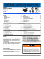
AFFINITY SERIES
BHZ024-060
ISO 9001
Certified Quality
2-5 Ton
Management System
TABLE OF CONTENTS
General . . . . . . . . . . . . . . . . . . . . . . . . . . . . . . . . . . . . . . . . . .
Installation . . . . . . . . . . . . . . . . . . . . . . . . . . . . . . . . . . . . . . . .
Limitations . . . . . . . . . . . . . . . . . . . . . . . . . . . . . . . . . . . . . .
Location. . . . . . . . . . . . . . . . . . . . . . . . . . . . . . . . . . . . . . . .
Rigging And Handling . . . . . . . . . . . . . . . . . . . . . . . . . . . . .
Ductwork . . . . . . . . . . . . . . . . . . . . . . . . . . . . . . . . . . . . . . .
Roof Curb . . . . . . . . . . . . . . . . . . . . . . . . . . . . . . . . . . . . . .
Filters . . . . . . . . . . . . . . . . . . . . . . . . . . . . . . . . . . . . . . . . .
Condensate Drain . . . . . . . . . . . . . . . . . . . . . . . . . . . . . . . .
Service Access . . . . . . . . . . . . . . . . . . . . . . . . . . . . . . . . . .
Thermostat . . . . . . . . . . . . . . . . . . . . . . . . . . . . . . . . . . . . .
Power And Control Wiring. . . . . . . . . . . . . . . . . . . . . . . . . .
1
3
3
4
4
7
7
7
7
8
8
8
Compressors. . . . . . . . . . . . . . . . . . . . . . . . . . . . . . . . . . .
Phasing . . . . . . . . . . . . . . . . . . . . . . . . . . . . . . . . . . . . . . .
Airflow Performance . . . . . . . . . . . . . . . . . . . . . . . . . . . . . . .
Operation . . . . . . . . . . . . . . . . . . . . . . . . . . . . . . . . . . . . . . .
Anti-short Cycle Timer. . . . . . . . . . . . . . . . . . . . . . . . . . . .
Cooling Sequence Of Operations . . . . . . . . . . . . . . . . . . .
Heating Sequence Of Operations . . . . . . . . . . . . . . . . . . .
Maintenance . . . . . . . . . . . . . . . . . . . . . . . . . . . . . . . . . . . . .
Normal Maintenance . . . . . . . . . . . . . . . . . . . . . . . . . . . . .
Troubleshooting . . . . . . . . . . . . . . . . . . . . . . . . . . . . . . . . . .
Typical Wiring Diagrams . . . . . . . . . . . . . . . . . . . . . . . . . .
11
11
12
14
14
14
15
17
17
17
18
LIST OF TABLES
1
2
3
4
5
6
7
Unit Limitations . . . . . . . . . . . . . . . . . . . . . . . . . . . . . . . . . 3
Unit Accessory Weights . . . . . . . . . . . . . . . . . . . . . . . . . . 5
Unit Dimensions Front . . . . . . . . . . . . . . . . . . . . . . . . . . . . 5
Unit Clearances . . . . . . . . . . . . . . . . . . . . . . . . . . . . . . . . . 5
Electrical Data . . . . . . . . . . . . . . . . . . . . . . . . . . . . . . . . . . 9
Physical Data . . . . . . . . . . . . . . . . . . . . . . . . . . . . . . . . . 10
Side Duct Application . . . . . . . . . . . . . . . . . . . . . . . . . . . 12
1
2
3
4
5
Component Location . . . . . . . . . . . . . . . . . . . . . . . . . . . .
Unit 4 Point Load Weight . . . . . . . . . . . . . . . . . . . . . . . . .
Unit Dimensions . . . . . . . . . . . . . . . . . . . . . . . . . . . . . . . .
Dimensions Front and Bottom . . . . . . . . . . . . . . . . . . . . .
Dimensions Back and Bottom . . . . . . . . . . . . . . . . . . . . .
8
9
10
11
12
13
14
Bottom Duct Application . . . . . . . . . . . . . . . . . . . . . . . . .
Additional Static Resistance . . . . . . . . . . . . . . . . . . . . . .
Electric Heat Minimum Supply Air . . . . . . . . . . . . . . . . .
Indoor Blower Specifications . . . . . . . . . . . . . . . . . . . . . .
Electric Heat Multipliers . . . . . . . . . . . . . . . . . . . . . . . . .
Thermostat Signals (Single Phase Units) . . . . . . . . . . . .
Thermostat Signals (Three Phase Units) . . . . . . . . . . . .
12
13
14
14
14
16
16
LIST OF FIGURES
3
4
5
6
6
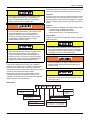
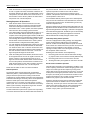
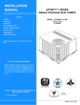
General
YORK® Affinity Model BHZ units are factory assembled heat
pumps designed for outdoor installation on a roof top or a slab.
Field-installed electric heater accessories are available to
provide supplemental electric heat combined with electric
cooling and heating.
The units are completely assembled on rigid, removable base
rails. All piping, refrigerant charge, and electrical wiring is
factory installed and tested. The units require only electric
power and duct connections at the point of installation.
The electric heaters have nickel-chrome resistance wire
elements and utilize single point power connection.
Safety Considerations
This is a safety alert symbol . When you see this symbol on
labels or in manuals, be alert to the potential for personal injury.
Understand and pay particular attention the signal words
DANGER, WARNING or CAUTION.
6
7
8
9
Roof Curb . . . . . . . . . . . . . . . . . . . . . . . . . . . . . . . . . . . . . 7
Typical Field Control Wiring Diagram . . . . . . . . . . . . . . . 8
Typical Field Power Wiring Diagram . . . . . . . . . . . . . . . . 9
R-410A Quick Reference Guide . . . . . . . . . . . . . . . . . . 21
DANGER indicates an imminently hazardous situation, which,
if not avoided, will result in death or serious injury.
WARNING indicates a potentially hazardous situation, which,
if not avoided, could result in death or serious injury.
CAUTION indicates a potentially hazardous situation, which, if
not avoided may result in minor or moderate injury. It is also
used to alert against unsafe practices and hazards involving
only property damage.
Improper installation may create a condition where the
operation of the product could cause personal injury or
property damage. Improper installation, adjustment,
alteration, service or maintenance can cause injury or
property damage. Refer to this manual for assistance or
for additional information, consult a qualified contractor,
installer or service agency.
268721-YIM-B-0807
268721-YIM-B-0807
Wear safety glasses and work gloves. Use quenching cloth and
have a fire extinguisher available during brazing operations.
Inspection
This product must be installed in strict compliance with
the installation instructions and any applicable local,
state and national codes including, but not limited to
building, electrical, and mechanical codes.
As soon as a unit is received, it should be inspected for possible
damage during transit. If damage is evident, the extent of the
damage should be noted on the carrier’s freight bill. A separate
request for inspection by the carrier’s agent should be made in
writing.
Reference
Additional information is available in the following reference forms:
• Technical Guide - BHZ024-060, 278726
• General Installation - BHZ024-060, 268721
• Electric Heat Accessory - 035-16605-003-E-0705
Before performing service or maintenance operations on
unit, turn off main power switch to unit. Electrical shock
could cause personal injury. Improper installation,
adjustment, alteration, service or maintenance can
cause injury or property damage. Refer to this manual.
For assistance or additional information consult a
qualified installer or service agency.
Renewal Parts
Contact your local York® parts distribution center for authorized
replacement parts.
This product must be installed in strict compliance with
the enclosed installation instructions and any applicable
local, state, and national codes including, but not limited
to, building, electrical, and mechanical codes.
This system uses R-410A Refrigerant which operates at
higher pressures than R-22. No other refrigerant may be
used in this system. Gage sets, hoses, refrigerant
containers and recovery systems must be designed to
handle R-410A. If you are unsure, consult the equipment
manufacturer. Failure to use R-410A compatible servicing
equipment may result in property damage or injury.
Due to system pressure, moving parts, and electrical
components, installation and servicing of air conditioning
equipment can be hazardous. Only qualified, trained service
personnel should install, repair, or service this equipment.
Untrained personnel can perform basic maintenance functions
of cleaning coils and filters and replacing filters.
Observe all precautions in the literature, labels, and tags
accompanying the equipment whenever working on air
conditioning equipment. Be sure to follow all other applicable
safety precautions and codes including.
Improper installation may create a condition where the
operation of the product could cause personal injury or
property damage.
This system uses R-410A Refrigerant which operates at
higher pressures than R-22. No other refrigerant may be
used in this system.
Nomenclature
B 2
HZ
024 A
06
Product Category
Voltage Code
B = Single Package Heat Pumps
(Air Cooled)
06 = 208/230-1-60
25 = 208/230-3-60
46 = 460-3-60
Product Generation
1 = New or Current Design
2 = Second Generation
Product Identifier
HZ = R-410A 13 SEER
2
Factory Installed Electric Heat
A = No Electric Heat Installed
Nominal Cooling Capacity (MBH)
024 = 24,000 BTUH
030 = 30,000 BTUH
036 = 36,000 BTUH
042 = 42,000 BTUH
048 = 48,000 BTUH
060 = 60,000 BTUH
Unitary Products Group
268721-YIM-B-0807
Installation
Refer to Table 6 for unit physical data and to Table 5 for electrical
data.
Limitations
These units must be installed in accordance with the following
national and local safety codes.
1.
National Electrical Code ANSI/NFPS No. 70 or Canadian
Electrical Code Part 1, C22.1 (latest editions).
2.
Local plumbing and waste water codes and other
applicable local codes.
If components are to be added to a unit to meet local codes,
they are to be installed at the dealer's and/or the customer's
expense.
Size of unit for proposed installation should be based on heat
loss/heat gain calculations made in accordance with industry
recognized procedures identified by the Air Conditioning
Contractors of America.
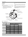
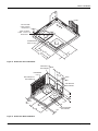
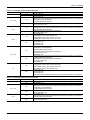
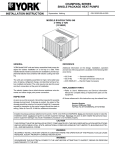
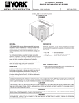
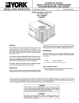
Direct Drive Condenser
Fan Motor
Highly Efficient Enhanced Copper
Tube/Aluminum Fin Indoor Coil
Highly Efficient Enhanced Copper
Tube/Aluminum Fin Outdoor Coil
Back And Bottom
Return Air and Supply
Air Duct Opening
Decorative Protective
Coil Guard
High Voltage
Terminal Block
Low Voltage
Terminal Block
5-Speed Direct Drive Blower Motor
With Slide-Out Blower Assembly
Long-Lasting
Powder Paint Finish
High-Efficiency Compressor
Rigidly Mounted
Heavy Gauge
Removable Base Rails
Figure 1: Component Location
Table 1:
Unit Limitations
Size
(Tons)
Unit Voltage
Unit Limitations
Applied Voltage
Min
Max
024
(2.0)
208/230-1-60
187
252
125
208/230-1-60
208/230-3-60
460-3-60
208/230-1-60
208/230-3-60
460-3-60
208/230-1-60
208/230-3-60
460-3-60
208/230-1-60
208/230-3-60
460-3-60
208/230-1-60
208/230-3-60
460-3-60
187
187
432
187
187
432
187
187
432
187
187
432
187
187
432
252
252
504
252
252
504
252
252
504
252
252
504
252
252
504
125
125
125
125
125
125
125
125
125
125
125
125
125
125
125
030
(2.5)
036
(3.0)
042
(3.5)
048
(4.0)
060
(5.0)
Unitary Products Group
Outdoor DB Temp
Max (°F)
3
268721-YIM-B-0807
Location
Rigging And Handling
Use the following guidelines to select a suitable location for
these units.
Exercise care when moving the unit. Do not remove any
packaging until the unit is near the place of installation. Rig the
unit by attaching chain or cable slings to the lifting holes
provided in the base rails. Spreader bars, whose length
exceeds the largest dimension across the unit, MUST be used
across the top of the unit.
1.
Unit is designed for outdoor installation only.
2.
Condenser must have an unlimited supply of air. Where a
choice of location is possible, position unit on either north
or east side of building.
3.
For ground level installation, a level pad or slab should be
used. The thickness and size of the pad or slab used
should meet local codes and unit weight. Do not tie the
slab to the building foundation.
4.
For roof top installation, be sure the structure can support
the weight of the unit plus any field installed components.
Unit must be installed on a level roof curb or appropriate
angle iron frame providing adequate support under the
compressor/condenser section.
5.
Maintain level tolerance of unit to 1/8" maximum.
If a unit is to be installed on a roof curb other than a
York® roof curb, gasketing must be applied to all
surfaces that come in contact with the unit underside.
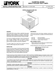
Before lifting, make sure the unit weight is distributed
equally on the rigging cables so it will lift evenly.
Units may be moved or lifted with a forklift. Slotted openings in
the base rails are provided for this purpose.
Do not permit overhanging structures or shrubs to
obstruct condenser air discharge outlet, combustion air
inlet or vent outlets.
Clearances
All panels must be secured in place when the unit is
lifted.
All units require certain clearances for proper operation and
service. Refer to Table 4 for the clearances required for
construction, servicing and proper unit operation.
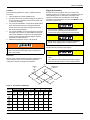
The condenser coils should be protected from rigging
cable damage with plywood or other suitable material.
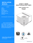
'
)5217
2)
81,7
&(17(52)
*5$9,7<
$
&
%
;
<
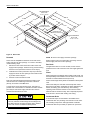
Figure 2: Unit 4 Point Load Weight
Weight (lbs.)
Center of Gravity
Size
(Tons) Shipping Operating
X
Y
024
360
355
22.25
25
(2.0)
030
355
350
22.25
25
(2.5)
036
395
390
22.25
25
(3.0)
042
445
440
22.25
25
(3.5)
048
490
485
22.25
25
(4.0)
060
500
495
22.25
25
(5.0)
4
4 Point Load Location (lbs.)
A
B
C
D
96
84
81
93
96
84
81
93
106
92
89
102
120
104
101
115
132
115
111
127
135
117
113
130
Unitary Products Group
268721-YIM-B-0807
Table 2:
Unit Accessory Weights
Unit Accessory
Model
Add Economizer
Add Electric Heat1
All
All
Weight (lbs.)
Shipping
Operating
45
40
13
12
1. Weight given is for the maximum heater size available (25 kW).
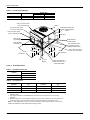
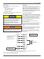
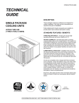
+,*+92/7$*(&211
',$.12&.287
)5217
&2035(66256(59,&(
$&&(66&203$570(17 3$1(/
+,*+92/7$*(&211
',$.12&.287
/2:92/7$*(&211
',$.12&.287
³$´
29(5$//
6,'(6833/<
$,523(1,1*
5()5,*(5$17
&211(&7,216
6,'(5(7851
$,523(1,1*
(/(&75,&$/),/7(5
6(59,&($&&(66
&203$570(173$1(/
29(5$//
+,*+92/7$*(&211
',$.12&.287
29(5$//
81,7&21'(16$7(
&211(&7,21137,
75$35(48,5('
Figure 3: Unit Dimensions
Table 3:
Unit Dimensions Front
Unit Size
Dimensions
“A”
024, 030, 036
33-1/2
042, 048, 060
41-1/2
Table 4:
Unit Clearances
Distance
(in.)
Direction
Distance
(in.)
Direction
Top1
36
Right
24
Front
12
Left
24
Rear
0
Bottom2 3
0
1. Units must be installed outdoors. Over hanging structure or shrubs should not obscure condenser air
discharge outlet.
2. Units may be installed on combustable floors made from wood or class A, B or C roof covering
materials.
3. Minimum Clearance of 1inch all sides of supply air duct for the first 3 foot of duct for 20 & 25 kW., zero
inches there after. For all other heaters, zero inch clearance all sides for entire length of duct.
Note: For units applied with a roof curb, the minimum clearance may be reduced from 1 inch to 1/2 inch
between combustible roof curb material and this supply air duct.
Unitary Products Group
5
268721-YIM-B-0807
)5217
/2:92/7$*(
&211',$
.12&.287
+,*+92/7$*(
&211[
.12&.287
&21'(16$7('
5$,1137,
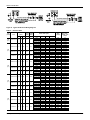
Figure 4: Dimensions Front and Bottom
6,'(6833/<
$,523(1,1*
&21'(16(5
&2,/
%$&.
%277206833/<
$,523(1,1*
6,'(5(7851
$,523(1,1*
%277205(7851
$,523(1,1*
Figure 5: Dimensions Back and Bottom
6
Unitary Products Group
268721-YIM-B-0807
5(&200(1'('
'8&76,=(
[
23(1,1*)25
5(7851$,5'8&7
23(1,1*)25
6833/<$,5'8&7
5(&200(1'('
'8&76,=(
[
Figure 6: Roof Curb1
Ductwork
NOTE: Be sure to note supply and return openings.
These units are adaptable to downflow use as well as rear
supply and return air duct openings. To convert to downflow,
use the following steps:
Refer to Figures 4 and 5 for information concerning rear and
bottom supply and return air duct openings.
1.
Remove the duct covers found in the bottom return and
supply air duct openings. There are four (4) screws securing
each duct cover (save these screws to use in Step 2).
2.
Install the duct covers (removed in step one) to the rear
supply and return air duct openings. Secure with the four
(4) screws used in step one.
3.
Seal duct covers with silicone caulk.
Duct work should be designed and sized according to the
methods of the Air Conditioning Contractors of America
(ACCA), as set forth in their Manual D.
A closed return duct system shall be used. This shall not
preclude use of economizers or ventilation air intake. Flexible
joints may be used in the supply and return duct work to
minimize the transmission of noise.
Roof Curb
On applications when a roof curb is used, the unit must be
positioned on the curb so the front of the unit is tight against the
curb.
Filters
Single phase units are shipped without a filter or filter racks. It is
the responsibility of the installer to secure a filter in the return air
ductwork or install a Filter/Frame Kit (1FF0114).
A filter rack and high velocity filters are standard on three phase
units.
Filters must always be used and must be kept clean. When
filters become dirt laden, insufficient air will be delivered by the
blower, decreasing your units efficiency and increasing
operating costs and wear-and-tear on the unit and controls.
Filters should be checked monthly; this is especially important
since this unit is used for both heating and cooling.
Condensate Drain
When fastening duct work to the side duct flanges on
the unit, insert the screws through the duct flanges only.
DO NOT insert the screws through the casing. Outdoor
duct work must be insulated and waterproofed.
A condensate trap is recommended to be installed in the
condensate drain. The plumbing must conform to local codes.
Use a sealing compound on male pipe threads. Install the
condensate drain line (3/4” NPTF) to spill into an open drain.
1. 8” Roof Curb also available.
Unitary Products Group
7
268721-YIM-B-0807
Service Access
Thermostat
Access to all serviceable components is provided at the
following locations:
The room thermostat should be located on an inside wall
approximately 56" above the floor where it will not be subject to
drafts, sun exposure or heat from electrical fixtures or
appliances. Follow manufacturer's instructions enclosed with
the thermostat for general installation procedure. Four color
coded insulated wires (minimum #18 AWG) should be used to
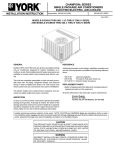
connect thermostat to unit. See Figure 7.
• Blower compartment access panel
• Electrical/Filter access panel
• Compressor access panel
• Refrigerant connections
Refer to Figures 1 and 3 for location of these access locations
and minimum clearances in Table 4.
Power And Control Wiring
Field wiring to the unit must conform to provisions of the current
N.E.C. ANSI/NFPA No. 70 or C.E.C. and/or local ordinances.
The unit must be electrically grounded in accordance with local
codes or, in their absence, with the N.E.C./C.E.C. Voltage
tolerances which must be maintained at the compressor
terminals during starting and running conditions are indicated
on the unit Rating Plate and Table 5.
This system uses R-410A Refrigerant which operates at
higher pressures than R-22. No other refrigerant may be
used in this system. Gage sets, hoses, refrigerant
containers and recovery systems must be designed to
handle R-410A. If you are unsure, consult the
equipment manufacturer. Failure to use R-410A
compatible servicing equipment may result in property
damage or injury.
The wiring entering the cabinet must be provided with
mechanical strain relief.
A fused disconnect switch should be field provided for the unit.
If any of the wire supplied with the unit must be replaced,
replacement wire must be of the type shown on the wiring
diagram.
Electrical line must be sized properly to carry the load. Each
unit must be wired with a separate branch circuit fed directly
from the meter panel and properly fused.
Wear safety glasses and gloves when handling
refrigerants. Failure to follow this warning can cause
serious personal injury.
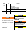
Refer to Figures 7 and 8 for typical field wiring and to the
appropriate unit wiring diagram for control circuit and power
wiring information.
Refer to Figure 9 for the R-410A quick reference guide.
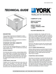
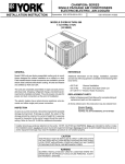
7+(50267$7
81,7&21752/%2$5'
7(50,1$/675,3
0LQLPXPZLUHVL]HRI$:*
ZLUHVKRXOGEHXVHGIRUDOOILHOG
LQVWDOOHGYROWZLUH
5
2QO\UHTXLUHGRQXQLWVZLWK
VXSSOHPHQWDOHOHFWULFKHDW
*
*
<
<
:
5
:
127(+($7$17,&,3$725
6+28/'%(6(7$7
$036)25$//02'(/6
92/7
75$16)250(5
:
352*5$00$%/(
7+(50267$721/<
2
2
&
&
&$87,21 /DEHO DOO ZLUHV SULRU WR GLVFRQQHFWLRQ ZKHQ VHUYLFLQJ FRQWUROV :LULQJ HUURUV FDQFDXVH LPSURSHU DQG
GDQJHURXV RSHUDWLRQ 9HULI\ SURSHU RSHUDWLRQ DIWHU VHUYLFLQJ
Figure 7: Typical Field Control Wiring Diagram
8
Unitary Products Group
268721-YIM-B-0807
Figure 8: Typical Field Power Wiring Diagram
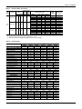
Table 5:
Electrical Data
Size
(Tons)
Volt
024
(2.0)
030
(2.5)
208/230-1-60 12.8
60
20
1.2
4.1
208/230-1-60 14.7
73
23
1.2
4.1
208/230-3-60 10.4
60
16
0.8
4.1
4.5
31
7
0.8
2.1
208/230-1-60 15.4
83
24
1.2
6.0
208/230-3-60 11.5
77
18
1.2
6.0
35
8
0.8
3.0
208/230-1-60 18.6 105
29
1.2
6.0
460-3-60
036
(3.0)
OD Fan Supply
Motors Blower
(each) Motor
RLA LRA MCC FLA
FLA
Compressors
(each)
460-3-60
5.1
Electric Heat Option
Model
None
2NH04500506
2NH04500706
2NH04501006
None
2NH04500506
2NH04500706
2NH04501006
2NH04501506
None
2NH04501025
2NH04501525
None
2NH04501046
2NH04501546
None
2NH04500506
2NH04500706
2NH04501006
2NH04501506
None
2NH04501025
2NH04501525
None
2NH04501046
2NH04501546
None
2NP04501006
2NP04501506
2ND04501506
042
(3.5)
208/230-3-60 13.4
88
21
1.2
6.0
39
10
0.8
3.0
208/230-1-60 21.1 113
33
1.2
6.0
208/230-3-60 16.0 120
25
1.2
6.0
13
0.8
3.0
460-3-60
048
(4.0)
460-3-60
6.4
8.3
60
Unitary Products Group
None
2NP04501025
2NP04501525
None
2NP04501046
2NP04501546
None
2NP04501006
2NP04501506
2NP04502006
2NP04502506
None
2NP04501025
2NP04501525
2NP04502025
2NP04502525
None
2NP04501046
2NP04501546
2NP04502046
2NP04502546
MCA1
(Amps)
kW
Stages
Amps
21.3
3.8 / 5
1
18.1 / 20.8 43.9 / 47.3
5.6 / 7.5
2
27.1 / 31.3 55.2 / 60.4
7.5 / 10
2
36.1 / 41.7 66.4 / 73.4
23.7
3.8 / 5
1
18.1 / 20.8 46.2 / 49.7
5.6 / 7.5
2
27.1 / 31.3 57.5 / 62.7
7.5 / 10
2
36.1 / 41.7 68.8 / 75.8
11.3 / 15
2
54.2 / 62.5 91.4 / 101.8
18.3
7.5 / 10
1
20.8 / 24.1 44.4 / 48.4
11.3 / 15
1
31.3 / 36.1 57.4 / 63.4
8.5
10
1
12
23.5
15
1
18
31
26.5
3.8 / 5
1
18.1 / 20.8
49 / 52.5
5.6 / 7.5
2
27.1 / 31.3 60.3 / 65.5
7.5 / 10
2
36.1 / 41.7 71.6 / 78.5
11.3 / 15
2
54.2 / 62.5 94.2 / 104.6
21.6
7.5 / 10
1
20.8 / 24.1 47.6 / 51.6
11.3 / 15
1
31.3 / 36.1 60.7 / 66.7
10.1
10
1
12
25.2
15
1
18
32.7
30.5
7.5 / 10
2
36.1 / 41.7 75.6 / 82.5
11.3 / 15
2
54.2 / 62.5 98.2 / 108.6
3.8 / 5
1
18.1 / 20.8
53 / 56.5
7.5 / 10
1
36.1 / 41.7 75.6 / 82.5
24
7.5 / 10
1
20.8 / 24.1
50 / 54
11.3 / 15
1
31.3 / 36.1
63 / 69.1
11.8
10
1
12
26.8
15
1
18
34.3
33.6
7.5 / 10
2
36.1 / 41.7 78.7 / 85.7
11.3 / 15
2
54.2 / 62.5 101.3 / 111.7
15 / 20
2
72.2 / 83.3 123.9 / 137.7
18.8 / 25
2
90.3 / 104.2 146.4 / 163.8
27.2
7.5 / 10
1
20.8 / 24.1 53.3 / 57.3
11.3 / 15
1
31.3 / 36.1 66.3 / 72.3
15 / 20
2
41.7 / 48.1 79.3 / 87.3
18.8 / 25
2
52.1 / 60.1 92.4 / 102.4
14.1
10
1
12
29.2
15
1
18
36.7
20
2
24.1
44.2
25
2
30.1
51.8
Max Fuse2/
Breaker3 Size
(Amps)
30
50 / 50
60 / 70
70 / 80
30
50 / 50
60 / 70
70 / 80
100 / 110
25
45 / 50
60 / 70
15
25
35
35
50 / 60
70 / 70
80 / 80
100 / 110
30
50 / 60
70 / 70
15
30
35
40
80 / 90
100 / 110
60 / 60
80 / 90
30
60 / 60
70 / 70
15
30
35
45
90 / 90
110 / 125
125 / 150
150 / 175
35
60 / 60
70 / 80
80 / 90
100 / 110
20
30
40
45
60
9
268721-YIM-B-0807
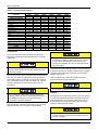
Table 5:
Electrical Data (Continued)
Size
(Tons)
Volt
060
(5.0)
OD Fan Supply
Motors Blower
(each) Motor
RLA LRA MCC FLA
FLA
Compressors
(each)
208/230-1-60 26.2 150
41
2.3
7.6
208/230-3-60 17.9 120
28
2.3
7.6
15
1.3
3.8
460-3-60
9.6
70
MCA1
(Amps)
Electric Heat Option
Model
None
2NP04501006
2NP04501506
2NH04502006
2NP04502506
None
2NH04501025
2NH04501525
2NH04502025
2NH04502525
None
2NP04501046
2NH04501546
2NH04502046
2NP04502546
kW
Stages
Amps
42.7
7.5 / 10
2
36.1 / 41.7 87.8 / 94.7
11.3 / 15
2
54.2 / 62.5 110.4 / 120.8
15 / 20
2
72.2 / 83.3 132.9 / 146.8
18.8 / 25
2
90.3 / 104.2 155.5 / 172.9
32.3
7.5 / 10
1
20.8 / 24.1 58.3 / 62.3
11.3 / 15
1
31.3 / 36.1 71.4 / 77.4
15 / 20
2
41.7 / 48.1 84.4 / 92.4
18.8 / 25
2
52.1 / 60.1 97.4 / 107.5
17.1
10
1
12
32.1
15
1
18
39.7
20
2
24.1
47.2
25
2
30.1
54.7
Max Fuse2/
Breaker3 Size
(Amps)
60
100 / 110
125 / 125
150 / 150
175 / 175
40
70 / 70
80 / 80
90 / 100
100 / 110
25
35
40
50
60
1. Minimum Circuit Ampacity.
2. Maximum Over Current Protection per standard UL 1995.
3. Fuse or HACR circuit breaker size installed at factory or field installed.
Table 6:
Physical Data
Component
BHZ024
2.0
Nominal Tonnage
ARI COOLING PERFORMANCE
Gross Capacity @ ARI A point (Btu)
22.9
ARI net capacity (Btu)
22.8
EER
11.4
SEER
13
Nominal CFM
800
System power (KW)
2.0
Refrigerant type
R410a
Refrigerant charge (lb-oz)
6-0
ARI HEATING PERFORMANCE
47°F Capacity Rating (Mbh)
22.2
System Power (Kw/COP)
3.4
17°F Capacity Rating (Mbh)
11.5
System Power (Kw/COP)
2.0
HSPF (BTU/Watts-hr.)
7.7
DIMENSIONS (inches)
Length
49 1/8
Width
47 1/4
Height
33 1/2
OPERATING WT. (lbs.)
350
COMPRESSORS
Type
Scroll 1-spd
Quantity
1
CONDENSER COIL DATA
Face area (Sq. Ft.)
11.7
Rows
1
Fins per inch
20
Tube diameter (in.)
3/8
Circuitry Type
Interlaced
Refrigerant control
Orifice
EVAPORATOR COIL DATA
Face area (Sq. Ft.)
4.38
Rows
2
Fins per inch
15
Tube diameter
3/8
Circuitry Type
Interlaced
Refrigerant control
Orifice
10
BHZ030
2.5
Models
BHZ036
BHZ042
3.0
3.5
BHZ048
4.0
BHZ060
5.0
29.7
29.2
11.25
13
950
2.6
R410a
7-4
36.0
33.6
11.0
13
1100
3.1
R410a
9-6
41.3
40.5
11.25
13
1400
3.6
R410a
12-0
47.2
45.5
10.65
13
1450
4.1
R410a
10-10
57.5
56.0
11.0
13
1550
5.10
R410a
11-8
27.8
3.3
14.6
2.0
7.7
32.8
3.0
19.2
2.3
7.7
40.0
3.0
23.2
2.3
7.7
45.5
3.0
27.4
2.2
7.7
56.0
2.90
33.0
2.0
7.7
49 1/8
47 1/4
33 1/2
350
49 1/8
47 1/4
33 1/2
385
49 1/8
47 1/4
41 1/2
435
49 1/8
47 1/4
41 1/2
480
49 1/8
47 1/4
41 1/2
490
Scroll 1-spd
1
Scroll 1-spd
1
Scroll 1-spd
1
Scroll 1-spd
1
Scroll 1-spd
1
11.7
1
20
3/8
Interlaced
Orifice
11.7
2
20
3/8
Interlaced
Orifice
16.4
2
20
3/8
Interlaced
Orifice
16.4
2
20
3/8
Interlaced
Orifice
16.4
2
20
3/8
Interlaced
TXV
4.38
3
13
3/8
Interlaced
Orifice
4.38
3
15
3/8
Interlaced
Orifice
5.63
3
15
3/8
Interlaced
Orifice
5.63
3
16
3/8
Interlaced
Orifice
5.63
3
16
3/8
Interlaced
TXV
Unitary Products Group
268721-YIM-B-0807
Table 6:
Physical Data (Continued)
Component
BHZ024
2.0
BHZ030
2.5
Models
BHZ036
BHZ042
3.0
3.5
BHZ048
BHZ060
Nominal Tonnage
4.0
5.0
CONDENSER FAN DATA
Fan diameter (Inch)
22
22
22
22
22
22
Type
Prop
Prop
Prop
Prop
Prop
Prop
Drive type
Direct
Direct
Direct
Direct
Direct
Direct
No. speeds
1
1
1
1
1
1
Number of motors
1
1
1
1
1
1
Motor HP each
1/4
1/4
1/4
1/4
1/4
1/2
RPM
850
850
850
850
850
1100
Nominal total CFM
1800
1800
2400
2400
3000
3000
DIRECT DRIVE EVAP FAN DATA
Quantity
1
1
1
1
1
1
Fan Size (Inch)
10 x 8
10 x 8
11 x 10
11 x 10
11 x 10
11 x 10
Type
Centrifugal
Centrifugal
Centrifugal
Centrifugal
Centrifugal
Centrifugal
No. speeds
5
5
5
5
5
5
Motor HP each
1/2
1/2
3/4
3/4
3/4
1
RPM
Variable
Variable
Variable
Variable
Variable
Variable
Frame size
48
48
48
48
48
48
FILTERS
Quantity - Size
2 - 22 x 14 x 1 2 - 22 x 14 x 1 2 - 22 x 14 x 1 2 - 22 x 14 x 1 2 - 22 x 14 x 1 2 - 22 x 14 x 1
Compressors
The scroll compressor used in this product is specifically
designed to operate with R-410A Refrigerant and cannot be
interchanged.
This system uses R-410A Refrigerant which operates at
higher pressures than R-22. No other refrigerant may be
used in this system.
The compressor also uses a polyolester (POE oil), Mobil 3MA
POE. This oil is extremely hydroscopic, meaning it absorbs
water readily. POE oil can absorb 15 times as much water as
other oils designed for HCFC and CFC refrigerants. Take all
necessary precautions to avoid exposure of the oil to the
atmosphere.
Exposure, even if immediately cleaned up, may cause
embrittlement (leading to cracking) to occur in one year
or more. When performing any service that may risk
exposure of compressor oil to the roof, take precautions
to protect roofing.
Procedures which risk oil leakage include, but are not limited to,
compressor replacement, repairing refrigerant leaks, replacing
refrigerant components such as filter drier, pressure switch,
metering device or coil.
Units are shipped with compressor mountings which are
factory-adjusted and ready for operation.
Do not loosen compressor mounting bolts.
Phasing
Do not leave the system open to the atmosphere. Unit
damage could occur due to moisture being absorbed by
the POE oil in the system. This type of oil is highly
susceptible to moisture absorption
POE (polyolester) compressor lubricants are known to cause
long term damage to some synthetic roofing materials.
Three-phase, scroll compressors operate in only one direction.
If the scroll is drawing low amperage, has similar suction and
discharge pressures, or is producing a high noise level, the
scroll is misphased. Change the incoming line connection
phasing to obtain the proper rotation.
Scroll compressors require proper rotation to operate
properly. Failure to check and correct rotation may result
in property damage.
Unitary Products Group
11
268721-YIM-B-0807
Airflow Performance
Table 7:
Side Duct Application
Model No.
BHZ
Low (1)
Low/Medium (2)
Medium (3)
Medium/High (4)
High (5)
Low (1)
Low/Medium (2)
Medium (3)
Medium/High (4)
High (5)
Low (1)
Low/Medium (2)
Medium (3)
Medium/High (4)
High (5)
Low (1)
Low/Medium (2)
Medium (3)
Medium/High (4)
High (5)
Low (1)
Low/Medium (2)
Medium (3)
Medium/High (4)
High (5)
Low (1)
Low/Medium (2)
Medium (3)
Medium/High (4)
High (5)
024
(2.0)
030
(2.5)
036
(3.0)
042
(3.5)
048
(4.0)
060
(5.0)
Table 8:
030
(2.5)
036
(3.0)
042
(3.5)
048
(4.0)
060
(5.0)
12
CFM
1.0
W
RPM
600
628
704
773
673
754
807
861
769
764
779
702
759
808
858
717
817
858
895
929
859
874
924
1030
1104
611
694
812
916
759
934
1041
1144
1235
906
1125
1276
1416
1151
1325
1461
1584
1687
1250
1513
1624
1726
1819
1504
1540
1663
1922
2089
979
1019
1052
1003
1033
1061
1086
987
981
993
1022
959
988
1019
1051
995
1021
1046
1069
1072
1134
1148
681
788
785
912
1007
971
1083
1182
1072
1223
1344
1428
1276
1386
1476
1547
1528
1576
230
266
273
316
352
397
460
521
396
468
542
615
501
571
639
706
659
689
1097
1120
1106
1132
1147
1048
1051
1070
1025
1046
1070
1097
1058
1077
1096
1112
1146
1154
CFM
0.2
W
RPM
External Static Pressure (Inches Water Gauge)
0.4
0.6
0.8
CFM W RPM CFM W RPM CFM W RPM
CFM
1.0
W
RPM
721
769
882
971
828
991
1091
1189
1025
1214
1370
1241
1406
1536
1656
1342
1596
1705
1806
1898
1580
1614
1733
2003
2214
82
93
131
171
110
168
214
269
158
237
305
221
299
376
466
249
397
476
561
652
394
419
508
737
968
600
628
704
773
673
754
807
861
769
764
779
702
759
808
858
717
817
858
895
929
859
874
924
1030
1104
611
694
812
916
759
934
1041
1144
1235
906
1125
1276
1416
1151
1325
1461
1584
1687
1250
1513
1624
1726
1819
1504
1540
1663
1922
2089
681
788
785
912
1007
971
1083
1182
1072
1223
1344
1428
1276
1386
1476
1547
1528
1576
230
266
273
316
352
397
460
521
396
468
542
615
501
571
639
706
659
689
1097
1120
1106
1132
1147
1048
1051
1070
1025
1046
1070
1097
1058
1077
1096
1112
1146
1154
CFM
0.2
W
721
769
882
971
828
991
1091
1189
1025
1214
1370
1241
1406
1536
1656
1342
1596
1705
1806
1898
1580
1614
1733
2003
2214
82
93
131
171
110
168
214
269
158
237
305
221
299
376
466
249
397
476
561
652
394
419
508
737
968
97
112
147
188
125
187
234
288
347
175
260
330
413
245
324
403
492
590
273
422
501
587
679
420
446
536
746
918
705
730
797
857
771
839
883
927
970
856
839
846
872
778
826
869
912
955
789
875
911
945
977
917
931
976
1069
1121
610
736
851
957
868
983
1091
1186
1034
1179
1314
1441
1058
1242
1384
1509
1611
1432
1545
1646
1736
1588
1829
1949
126
162
205
249
205
253
305
360
283
354
436
530
268
349
427
515
610
447
526
610
698
559
746
859
832
889
939
982
922
958
994
1028
913
913
932
970
853
893
928
966
1004
934
966
995
1023
1026
1104
1136
651
775
887
783
910
1027
1125
942
1078
1206
1326
1158
1305
1430
1527
1354
1466
1564
1646
1501
1712
1785
177
219
261
221
269
318
368
307
377
454
538
373
449
533
620
474
549
628
709
572
728
787
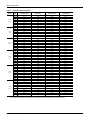
Bottom Duct Application
Model No.
BHZ
024
(2.0)
RPM
External Static Pressure (Inches Water Gauge)
0.4
0.6
0.8
CFM W RPM CFM W RPM CFM W RPM
Blower Speed Setting
Blower Speed Setting
Low (1)
Low/Medium (2)
Medium (3)
Medium/High (4)
High (5)
Low (1)
Low/Medium (2)
Medium (3)
Medium/High (4)
High (5)
Low (1)
Low/Medium (2)
Medium (3)
Medium/High (4)
High (5)
Low (1)
Low/Medium (2)
Medium (3)
Medium/High (4)
High (5)
Low (1)
Low/Medium (2)
Medium (3)
Medium/High (4)
High (5)
Low (1)
Low/Medium (2)
Medium (3)
Medium/High (4)
High (5)
97
112
147
188
125
187
234
288
347
175
260
330
413
245
324
403
492
590
273
422
501
587
679
420
446
536
746
918
705
730
797
857
771
839
883
927
970
856
839
846
872
778
826
869
912
955
789
875
911
945
977
917
931
976
1069
1121
610
736
851
957
868
983
1091
1186
1034
1179
1314
1441
1058
1242
1384
1509
1611
1432
1545
1646
1736
1588
1829
1949
126
162
205
249
205
253
305
360
283
354
436
530
268
349
427
515
610
447
526
610
698
559
746
859
832
889
939
982
922
958
994
1028
913
913
932
970
853
893
928
966
1004
934
966
995
1023
1026
1104
1136
651
775
887
783
910
1027
1125
942
1078
1206
1326
1158
1305
1430
1527
1354
1466
1564
1646
1501
1712
1785
177
219
261
221
269
318
368
307
377
454
538
373
449
533
620
474
549
628
709
572
728
787
979
1019
1052
1003
1033
1061
1086
987
981
993
1022
959
988
1019
1051
995
1021
1046
1069
1072
1134
1148
Unitary Products Group
268721-YIM-B-0807
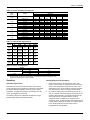
Table 9:
Size
(Tons)
024
(2.0)
030
(2.5)
036
(3.0)
042
(3.5)
048
(4.0)
060
(5.0)
Additional Static Resistance
CFM
Wet Indoor Coil
Economizer1
Filter/Frame Kit
Electric Heat
500
600
700
800
900
1000
1100
1200
700
800
900
1000
1100
1200
1300
700
800
900
1000
1100
1200
1300
1400
1100
1200
1300
1400
1500
1600
1700
1800
1900
2000
1100
1200
1300
1400
1500
1600
1700
1800
1900
2000
1100
1200
1300
1400
1500
1600
1700
1800
1900
2000
0.01
0.01
0.01
0.01
0.01
0.02
0.03
0.04
0.01
0.01
0.01
0.02
0.03
0.04
0.07
0.01
0.01
0.01
0.02
0.03
0.04
0.04
0.04
0.03
0.04
0.04
0.04
0.04
0.04
0.05
0.05
0.06
0.07
0.03
0.04
0.04
0.04
0.04
0.04
0.05
0.05
0.06
0.07
0.03
0.04
0.04
0.04
0.04
0.04
0.05
0.05
0.06
0.07
0.00
0.00
0.00
0.01
0.01
0.01
0.01
0.02
0.00
0.01
0.01
0.01
0.01
0.02
0.03
0.00
0.01
0.01
0.01
0.01
0.02
0.03
0.04
0.01
0.02
0.03
0.04
0.05
0.06
0.07
0.07
0.08
0.08
0.01
0.02
0.03
0.04
0.05
0.06
0.07
0.07
0.08
0.08
0.01
0.02
0.03
0.04
0.05
0.06
0.07
0.07
0.08
0.08
0.01
0.02
0.02
0.02
0.02
0.02
0.03
0.03
0.02
0.02
0.02
0.02
0.03
0.03
0.17
0.02
0.02
0.02
0.02
0.03
0.03
0.03
0.03
0.03
0.03
0.03
0.03
0.04
0.05
0.05
0.06
0.06
0.07
0.03
0.03
0.03
0.03
0.04
0.05
0.05
0.06
0.06
0.07
0.03
0.03
0.03
0.03
0.04
0.05
0.05
0.06
0.06
0.07
0.02
0.03
0.03
0.03
0.04
0.04
0.05
0.06
0.03
0.03
0.04
0.04
0.05
0.06
0.03
0.03
0.04
0.04
0.05
0.06
0.07
0.08
0.05
0.06
0.07
0.08
0.09
0.10
0.11
0.11
0.11
0.12
0.05
0.06
0.07
0.08
0.09
0.10
0.11
0.11
0.11
0.12
0.05
0.06
0.07
0.08
0.09
0.10
0.11
0.11
0.11
0.12
1. The pressure drop through the economizer is greater for 100% outdoor air than for 100% return air. If the resistance
of the return air duct is less than 0.25 IWG, the unit will deliver less CFM during full economizer operation.
Unitary Products Group
13
268721-YIM-B-0807
Table 10: Electric Heat Minimum Supply Air
Minimum Supply Air (CFM)
Heater kW
10.0
15.0
Size
(Tons)
Voltage
5.0
7.5
024
(2.0)
208/230-1-60
630
630
800
-
-
-
208/230-1-60
208/230-3-60
460-3-60
208/230-1-60
208/230-3-60
460-3-60
208/230-1-60
208/230-3-60
460-3-60
208/230-1-60
208/230-3-60
460-3-60
208/230-1-60
208/230-3-60
460-3-60
630
630
630
1070
1070
1070
1225
1225
1225
-
630
630
630
1070
1070
1070
1225
1225
1225
-
800
800
800
1070
1070
1070
1225
1225
1225
1200
1200
1200
1615
1615
1615
800
800
800
1070
1070
1070
1225
1225
1225
1430
1430
1430
1615
1615
1615
1430
1430
1430
1955
1955
1955
1430
1430
1430
1955
1955
1955
030
(2.5)
036
(3.0)
042
(3.5)
048
(4.0)
060
(5.0)
20.0
25.0
Table 11: Indoor Blower Specifications
Size
(Tons)
024
(2.0)
030
(2.5)
036
(3.0)
042
(3.5)
048
(4.0)
060
(5.0)
HP
RPM
Motor
Eff.
SF
Frame
1/2
Variable
0.8
1.0
48
1/2
Variable
0.8
1.0
48
3/4
Variable
0.8
1.0
48
3/4
Variable
0.8
1.0
48
3/4
Variable
0.8
1.0
48
1
Variable
0.8
1.0
48
Table 12: Electric Heat Multipliers
Voltage
Nominal
240
480
Applied
208
230
460
kW Capacity Multipliers1
0.75
0.92
0.92
1. Electric heaters are rated at nominal voltage. Use this table to determine the electric heat
capacity for heaters applied at lower voltages.
Operation
Cooling Sequence Of Operations
Anti-short Cycle Timer
1.
This unit has an anti-short cycle timer built in to the defrost
control. This timer will not permit the compressor to start within
five minutes after the completion of the last cycle or power
interruption. To bypass the anti-short cycle feature, short the
“TEST” pins together for 2 seconds.
The following sequences of operation are based on using a
standard single-stage heat pump thermostat.
14
2.
When the fan switch on the thermostat is in the “ON”
position, the 24 volts at “G” will bring on the indoor blower
motor at the cooling airflow. When the fan switch on the
thermostat is in the “AUTO” position, the blower operates
only when there is a call for cooling by the thermostat.
On a call for cooling, the thermostat sends 24 volts to “Y”
and “O” on the fan control and defrost control boards. The
reversing valve solenoid is energized, and after the antishort cycle period is complete contactor coil M1 is
energized. Power is supplied to the compressor and
outdoor fan motor, and the reversing valve switched to the
cooling position. When the fan switch on the thermostat is
in the “AUTO” position the indoor blower motor is
energized at the cooling airflow.
Unitary Products Group
268721-YIM-B-0807
3.
When the demand for cooling has been satisfied, the
24 volt “Y” signal is removed, and the M1 contactor is deenergized. When the fan switch on the thermostat is in the
“ON” position, the indoor blower motor continues to run. If
the fan switch is in the “AUTO” position. the indoor motor
ramps down over a 30-second period.
Heating Sequence Of Operations
1.
2.
3.
4.
When the fan switch on the thermostat is in the “ON”
position, the 24 volts at “G” brings on the indoor blower
motor at the heating flow. When the fan switch on the
thermostat is in the “AUTO” position, the blower operates
when there is a call for heating by the thermostat.
On a call for heating, the thermostat sends 24 volts to “Y” on
the fan control board. After the anti-short cycle period is
complete, the 24 volt signal energizes contactor coil M1 and
power is supplied to the compressor and outdoor fan motor.
The reversing valve remains in the heating position. When
the fan switch on the thermostat is in the “AUTO” position,
the indoor blower is energized at the heating airflow.
For units equipped with supplementary electric heat, when
the heat pump cannot meet the demand, the thermostat
“W” sends 24 volts to “W2” on the fan control board. This
signal also is sent through the defrost control terminals “W”
and “W6” and back to the fan control “W1”. The 24 volt
signal energizes all stages of electric heat.
When the heating demand is satisfied, the electric heat is
de-energized when the 24 volt “W” signal is removed, and
the M1 contactor is de-energized when the 24 volt “Y”
signal is removed. When the fan switch on the thermostat
is in the “ON” position, the indoor blower continues to run.
When the fan switch is in the “AUTO” position, the indoor
blower motor ramps down over a 15-second period.
Please refer to Tables 13 and 14 for more information.
Defrost Operation
The demand defrost control implements a temperature
differential (”delta-T”) demand defrost algorithm. The heat
pump is allowed to operate in the heating mode until the
combination of outdoor ambient and outdoor coil temperatures
indicate that defrosting is necessary. When coil temperature is
below the initiate point for the ambient temperature
continuously for 4-1/2 minutes, the heat pump is put into a
defrost cycle. This 4-1/2 minute timer eliminates unnecessary
defrost cycles caused by refrigeration surges such as those
that occur at the start of a heating cycle.
A timed inhibit feature prevents the system from responding
to a call for defrost less than 20 minutes after the initiation of
Unitary Products Group
the previous defrost. After the 20 minute inhibit time has
expired, temperature conditions must call for defrost
continuously for 4-1/2 minutes before a defrost cycle is
initiated. A temperature inhibit feature prohibits defrost if the
coil temperature is above 40°F.
A forced-defrost feature puts the system into a defrost period
every 6 hours and 4 minutes to recirculate lubricants, unless the
coil temperature is above 40°F. All defrost timing occurs only
while the compressor is on.
During the defrost mode, the defrost control will provide a 24 volt
signal from terminal “W1/66” to the fan control terminal “W1”. This
signal will energize electric heat stage 1, if the unit is so equipped.
For trouble shooting purposes, the defrost cycle can be manually
initiated by shorting the “TEST” pins together for 5 seconds.
Defrost will terminate normally during the “TEST” mode.
Heat Pump Safety Switch Operation
The unit is equipped with a safety package. The refrigeration
system will be protected against high or low refrigerant
pressure. If either of these safety switches opens, the unit will
be shut off for the 5 minute anti-short cycle time. Once this has
expired, a six hour elapsed run timer begins. If a second
opening of a safety switch occurs during this six hour period,
the compressor will be locked out.
Resetting the lockout function is accomplished by:
1. Removing power from the control's thermostat 1st stage
(Y) input for a time not to exceed 5 seconds (ON-OFF-ON).
2.
Removing power from “R” for more than 2 seconds.
3.
Shorting the “TEST” pins together for more than 2 seconds.
Electric Heat Limit Switch Operation
The limit switch responds to over temperature conditions in the
air duct. Opening of the device results in dropping power to the
relays. The control logic will also respond by turning off the
relays. After four limit cycle trips the unit goes into a 1 hour soft
lockout period. If during this period the control “sees” another
limit cycle, the unit will go into a hard lockout condition. Once in
a hard lockout state, the fan is locked on and the heaters are
disabled. Only a power cycle will clear this state.
During the soft lockout period, the fan responds to thermostat
input but the heaters are enabled. This is to sense a failed
heater relay. The limit cycle count is reset at the start of a heat
request. If the limit remains open for period of 80 seconds or
more, the control is immediately put into a hard lockout
condition. Only a power cycle will clear this state.
15
268721-YIM-B-0807
Table 13: Thermostat Signals (Single Phase Units)
Signal
G
State
ON
OFF
ON
G&Y&O
OFF
ON
G&Y
OFF
ON
G&W
OFF
ON
G&Y&W
OFF
ON
W
OFF
Board Function
FAN INSTANT ON
FAN INSTANT OFF
FAN INSTANT ON
COMPRESSOR AND OUTDOOR FAN INSTANT ON (AFTER ANTI-SHORT CYCLE DELAY)
REVERSING VALVE ENERGIZED
SYSTEM OPERATES IN COOLING
COMPRESSOR AND OUTDOOR FAN INSTANT OFF
FAN 60 SEC. DELAY OFF
FAN INSTANT ON
COMPRESSOR AND OUTDOOR FAN INSTANT ON (AFTER ANTI-SHORT CYCLE DELAY)
SYSTEM OPERATES IN HEATING
COMPRESSOR AND OUTDOOR FAN INSTANT OFF
FAN 60 SEC. DELAY OFF
FAN INSTANT ON
HEATER BANK 1 ELEC. HEAT INSTANT ON
HEATER BANK 2 ELEC. HEAT 10 SEC. DELAY ON
HEATER BANK 3 ELEC. HEAT 20 SEC. DELAY ON
HEATER BANK 3 ELEC. HEAT INSTANT OFF
FAN INSTANT ON
FAN INSTANT OFF
FAN INSTANT ON
COMPRESSOR AND OUTDOOR FAN INSTANT ON (AFTER ANTI-SHORT CYCLE DELAY)
Table 14: Thermostat Signals (Three Phase Units)
Signal
G
State
ON
OFF
ON
G&Y&O
OFF
ON
G&Y
OFF
16
Board Function
FAN INSTANT ON
FAN INSTANT OFF
FAN INSTANT ON
COMPRESSOR AND OUTDOOR FAN INSTANT ON (AFTER ANTI-SHORT CYCLE DELAY)
REVERSING VALVE ENERGIZED
SYSTEM OPERATES IN COOLING
COMPRESSOR AND OUTDOOR FAN INSTANT OFF
FAN 60 SEC. DELAY OFF
FAN INSTANT ON
COMPRESSOR AND OUTDOOR FAN INSTANT ON (AFTER ANTI-SHORT CYCLE DELAY)
SYSTEM OPERATES IN HEATING
COMPRESSOR AND OUTDOOR FAN INSTANT OFF
FAN 60 SEC. DELAY OFF
Unitary Products Group
268721-YIM-B-0807
Table 14: Thermostat Signals (Three Phase Units) (Continued)
Signal
State
ON
G&W
OFF
ON
G&Y&W
OFF
ON
W
OFF
Board Function
FAN INSTANT ON
HEATER BANK 1, 2 & 3 ELEC. HEAT INSTANT ON
HEATER BANK 4, 5 & 6 ELEC. HEAT 10 SEC. DELAY ON
HEATER BANK 4, 5 & 6 ELEC. HEAT INSTANT OFF
HEATER BANK 1, 2 & 3 ELEC. HEAT SEC. DELAY OFF
FAN 10 SEC. DELAY OFF
FAN INSTANT ON
COMPRESSOR AND OUTDOOR FAN INSTANT ON
SYSTEM OPERATES IN HEATING
HEATER BANK 1, 2 & 3 ELEC. HEAT INSTANT ON
HEATER BANK 4, 5 & 6 ELEC. HEAT 10 SEC. DELAY ON
COMPRESSOR AND OUTDOOR FAN INSTANT OFF
HEATER BANK 4, 5 & 6 ELEC. HEAT INSTANT OFF
HEATER BANK 1, 2 & 3 ELEC. HEAT SEC. DELAY OFF
FAN 60 SEC. DELAY OFF
FAN INSTANT ON
HEATER BANK 1, 2 & 3 ELEC. HEAT INSTANT ON
HEATER BANK 4, 5 & 6 ELEC. HEAT 10 SEC. DELAY ON
HEATER BANK 4, 5 & 6 ELEC. HEAT INSTANT OFF
HEATER BANK 1, 2 & 3 ELEC. HEAT SEC. DELAY OFF
FAN 10 SEC. DELAY OFF
Maintenance
Normal Maintenance
Exercise care when cleaning the coil so that the coil fins
are not damaged.
Prior to any of the following maintenance procedures,
shut off all power to the unit, to avoid personal injury.
Do not permit the hot condenser air discharge to be
obstructed by overhanging structures or shrubs.
Troubleshooting
Periodic maintenance consists of changing or cleaning filters
and general cleaning of the outdoor coil.
FILTERS - Inspect once a month. Replace Disposable or clean
Permanent Type as necessary. DO NOT replace Permanent
Type with Disposable.
MOTORS - Indoor and outdoor fan motors are permanently
lubricated and require no maintenance.
OUTDOOR COIL - Dirt should not be allowed to accumulate on
the outdoor coil surface or other parts in the air circuit. Cleaning
should be as often as necessary to keep the coil clean. Use a
brush, vacuum cleaner attachment, or other suitable means. If
water is used to clean the coil, be sure that the power to the unit
is shut off prior to cleaning.
Troubleshooting of components necessarily requires
opening the electrical control box with the power
connected to the unit. Use extreme care when working
with live circuit! Check the unit nameplate for the correct
range before making any connections with line
terminals.
The wire number or color and terminal designations
referred to may vary. Check the wiring label inside the
control box access panel for the correct wiring.
Unitary Products Group
17
268721-YIM-B-0807
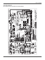
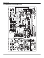
Typical Wiring Diagrams
Typical BHZ024-060 Heat Pump 208/230-1-60 volt Wiring Diagram
18
Unitary Products Group
268721-YIM-B-0807
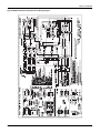
Typical BHZ030-060 Heat Pump 230-3-60 volt Wiring Diagram
Unitary Products Group
19
268721-YIM-B-0807
Typical BHZ030-060 Heat Pump 460-3-60 volt Wiring Diagram
20
Unitary Products Group
268721-YIM-B-0807
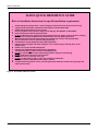
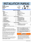
R-410A QUICK REFERENCE GUIDE
Refer to Installation Instructions for specific installation requirements.
R-410A Refrigerant operates at 50 - 70 percent higher pressures than R-22. Be sure that servicing
equipment and replacement components are designed to operate with R-410A.
R-410A Refrigerant cylinders are rose colored.
Recovery cylinder service pressure rating must be 400 psig, DOT 4BA400, or DOT BW400.
Recovery equipment must be rated for R-410A.
Do Not use R-410A service equipment on R-22 systems. All hoses, gages, recovery cylinders, charging
cylinders and recovery equipment must be dedicated for use on R-410A systems only.
Manifold sets must be at least 700 psig high side, and 180 psig low side, with 550 psig retard.
All hoses must have a service pressure rating of 800 psig.
Leak detectors must be designed to detect HFC refrigerants.
Systems must be charged with liquid refrigerant. Use a commercial type metering device in the
manifold hose.
R-410A can only be used with POE type oils.
POE type oils rapidly absorb moisture from the atmosphere.
Vacuum pumps will not remove moisture from POE type oils.
Do not use liquid line driers with a rated working pressure rating less than 600 psig.
Do not install suction line driers in the liquid line.
A liquid line drier is required on every unit.
Do not use a R-22 TXV. If a TXV is to be used, it must be a R-410A TXV.
Never open system to atmosphere when under a vacuum.
If system must be opened for service, evacuate system then break the vacuum with dry nitrogen and
replace all filter driers.
Figure 9: R-410A Quick Reference Guide
Unitary Products Group
21
268721-YIM-B-0807
22
Unitary Products Group
268721-YIM-B-0807
Unitary Products Group
23
Subject to change without notice. Printed in U.S.A.
Copyright © 2007 by Unitary Products Group. All rights reserved.
Unitary
Products
Group
268721-YIM-B-0807
Supersedes: 268721-YIM-A-1106
5005
York
Drive
Norman
OK
73069