1
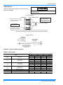
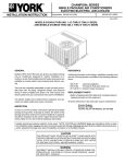
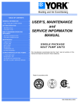
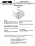
INSTALLATION
MANUAL
CONTENTS
GENERAL . . . . . . . . . . . . . . . . . . . . . . . . . . . . . . . . . . . .3
INSPECTION . . . . . . . . . . . . . . . . . . . . . . . . . . . . . . . . . .3
REFERENCE . . . . . . . . . . . . . . . . . . . . . . . . . . . . . . . . . .3
AFFINITY™ SERIES
SINGLE PACKAGE HEAT PUMPS
MODEL: B1HA036 thru 060
3 thru 5 Ton
(10 SEER)
REPLACEMENT PARTS . . . . . . . . . . . . . . . . . . . . . . . . .3
PRODUCT NOMENCLATURE . . . . . . . . . . . . . . . . . . . .3
INSTALLATION . . . . . . . . . . . . . . . . . . . . . . . . . . . . . . . .4
SEQUENCE OF OPERATION . . . . . . . . . . . . . . . . . . . .13
MAINTENANCE . . . . . . . . . . . . . . . . . . . . . . . . . . . . . . .15
See the following page for a complete Table of Contents.
NOTES, CAUTIONS AND WARNINGS
Installer should pay particular attention to the words:
NOTE, CAUTION, and WARNING. Notes are
intended to clarify or make the installation easier.
Cautions are given to prevent equipment damage.
Warnings are given to alert installer that personal
injury and/or equipment damage may result if installation procedure is not handled properly.
CAUTION: READ ALL SAFETY GUIDES BEFORE
YOU BEGIN TO INSTALL YOUR UNIT.
ISO 9001
Certified Quality
SAVE THIS MANUAL
Management System
341849-YIM-A-0108
341849-YIM-A-0108
TABLE OF CONTENTS
GENERAL . . . . . . . . . . . . . . . . . . . . . . . . . . . . . . . . . . . . . . 3
Fig. #
INSPECTION . . . . . . . . . . . . . . . . . . . . . . . . . . . . . . . . . . . . 3
6
TYPICAL WIRING DIAGRAM BHA MODELS
(460-3-60 AND 575-3-60 POWER SUPPLY) . . . . . . . 17
REPLACEMENT PARTS . . . . . . . . . . . . . . . . . . . . . . . . . . . 3
7
TYPICAL WIRING DIAGRAM LEGEND . . . . . . . . . . . 18
PRODUCT NOMENCLATURE . . . . . . . . . . . . . . . . . . . . . . 3
8
TYPICAL WIRING DIAGRAM NOTES . . . . . . . . . . . . 18
REFERENCE . . . . . . . . . . . . . . . . . . . . . . . . . . . . . . . . . . . . 3
INSTALLATION . . . . . . . . . . . . . . . . . . . . . . . . . . . . . . . . . . 4
Pg. #
LIST OF TABLES
LIMITATIONS . . . . . . . . . . . . . . . . . . . . . . . . . . . . . . . 4
LOCATION . . . . . . . . . . . . . . . . . . . . . . . . . . . . . . . . . 4
Tbl. #
RIGGING AND HANDLING . . . . . . . . . . . . . . . . . . . . 4
1
UNIT APPLICATION DATA . . . . . . . . . . . . . . . . . . . . . 4
2
UNIT DIMENSIONS . . . . . . . . . . . . . . . . . . . . . . . . . . . 4
3
PHYSICAL DATA . . . . . . . . . . . . . . . . . . . . . . . . . . . . . 6
4
ELECTRICAL DATA (HEAT PUMP /
ELECTRIC HEAT) . . . . . . . . . . . . . . . . . . . . . . . . . . . . 7
THERMOSTAT . . . . . . . . . . . . . . . . . . . . . . . . . . . . . . 5
5
ELECTRICAL DATA (BASIC UNIT) . . . . . . . . . . . . . . . 7
POWER AND CONTROL WIRING . . . . . . . . . . . . . . . 5
6
SIDE & BOTTOM SUPPLY AIR BLOWER
PERFORMANCE 230/460/575 VOLTS . . . . . . . . . . . . 8
7
SIDE & BOTTOM SUPPLY AIR BLOWER
PERFORMANCE 208 VOLTS . . . . . . . . . . . . . . . . . . . 8
ANTI-SHORT CYCLE TIMER . . . . . . . . . . . . . . . . . . 13
8
ADDITIONAL STATIC PRESSURE RESISTANCE . . . 8
COOLING OPERATION . . . . . . . . . . . . . . . . . . . . . . 13
9
COOLING SUPERHEAT AT COMPRESSOR SUCTION,
AIRFLOW = 1,200 CFM (B1HA036) . . . . . . . . . . . . . . 10
CLEARANCES . . . . . . . . . . . . . . . . . . . . . . . . . . . . . . 4
DUCTWORK . . . . . . . . . . . . . . . . . . . . . . . . . . . . . . . . 5
FILTERS . . . . . . . . . . . . . . . . . . . . . . . . . . . . . . . . . . . 5
CONDENSATE DRAIN . . . . . . . . . . . . . . . . . . . . . . . . 5
SERVICE ACCESS . . . . . . . . . . . . . . . . . . . . . . . . . . 5
COMPRESSORS . . . . . . . . . . . . . . . . . . . . . . . . . . . . 6
CHECKING SUPPLY AIR CFM . . . . . . . . . . . . . . . . . 9
SEQUENCE OF OPERATION . . . . . . . . . . . . . . . . . . . . . . 13
HEATING OPERATION . . . . . . . . . . . . . . . . . . . . . . 13
DEFROST OPERATION . . . . . . . . . . . . . . . . . . . . . 13
HEAT PUMP SAFETY SWITCH OPERATION . . . . 14
ELECTRIC HEAT LIMIT SWITCH OPERATION . . . 14
MAINTENANCE . . . . . . . . . . . . . . . . . . . . . . . . . . . . . . . . . 15
NORMAL MAINTENANCE . . . . . . . . . . . . . . . . . . . . 15
LIST OF FIGURES
Fig. #
Pg. #
1
CENTER OF GRAVITY . . . . . . . . . . . . . . . . . . . . . . . . 4
2
TYPICAL FIELD WIRING DIAGRAM . . . . . . . . . . . . . . 6
3
COIL DELTA P VS. SUPPLY AIR CFM . . . . . . . . . . . . 9
4
DIMENSIONS AND CLEARANCES . . . . . . . . . . . . . . 12
5
TYPICAL WIRING DIAGRAM (230-3-60 POWER
SUPPLY) . . . . . . . . . . . . . . . . . . . . . . . . . . . . . . . . . . 16
2
Pg. #
10 HEATING SUPERHEAT AT COMPRESSOR SUCTION,
AIRFLOW = 1,200 CFM (B1HA036) . . . . . . . . . . . . . . 10
11 COOLING SUPERHEAT AT COMPRESSOR SUCTION,
AIRFLOW = 1,400 CFM (B1HA042) . . . . . . . . . . . . . . 10
12 HEATING SUPERHEAT AT COMPRESSOR SUCTION,
AIRFLOW = 1,400 CFM (B1HA042) . . . . . . . . . . . . . . 10
13 COOLING SUPERHEAT AT COMPRESSOR SUCTION,
AIRFLOW = 1,600 CFM (B1HA048) . . . . . . . . . . . . . . 11
14 HEATING SUPERHEAT AT COMPRESSOR SUCTION,
AIRFLOW = 1,600 CFM (B1HA048) . . . . . . . . . . . . . . 11
15 COOLING SUPERHEAT AT COMPRESSOR SUCTION,
AIRFLOW = 2,000 CFM (B1HA060) . . . . . . . . . . . . . . 11
16 HEATING SUPERHEAT AT COMPRESSOR SUCTION,
AIRFLOW = 2,000 CFM (B1HA060) . . . . . . . . . . . . . . 11
17 THERMOSTAT SIGNALS (THREE PHASE
UNITS) . . . . . . . . . . . . . . . . . . . . . . . . . . . . . . . . . . . . 14
Johnson Controls Unitary Products
341849-YIM-A-0108
GENERAL
REPLACEMENT PARTS
YORK Model B1HA units are factory assembled heat
pumps designed for outdoor installation on a rooftop or
a slab. Field-installed electric heater accessories are
available to provide supplemental electric heat combined with electric cooling and heating.
Contact your local York® parts distribution center for
authorized replacement parts.
The units are completely assembled on rigid, removable base rails. All piping, refrigerant charge, and electrical wiring is factory installed and tested. The units
require only electric power and duct connections at the
point of installation.
This product must be installed in strict compliance with the enclosed installation instructions
and any applicable local, state, and national
codes including, but not limited to, building,
electrical, and mechanical codes.
The electric heaters have nickel-chrome resistance wire
elements and utilize single point power connection.
INSPECTION
Improper installation may create a condition
where the operation of the product could cause
personal injury or property damage.
As soon as a unit is received, it should be inspected for
possible damage during transit. If damage is evident,
the extent of the damage should be noted on the carrier's freight bill. A separate request for inspection by
the carrier's agent should be made in writing.
REFERENCE
De-energize the electrical power to the unit
before attempting to inspect, repair or perform
maintenance to the unit.
Additional information on the design, installation, operation and service of this equipment is available in the
following reference forms:
•
341849 - General Installation
•
035-16605-003 - Electric Heater Accessory
PRODUCT NOMENCLATURE
PRODUCT NOMENCLATURE
B
1
H A
0
3
6
A
PRODUCT CATEGORY
B = Single Package Heat Pumps
(Air Cooled)
2
5
VOLTAGE CODE
25 = 208/230-3-60
46 = 460-3-60
58 = 575-3-60
PRODUCT GENERATION
1 = NEW or Current Design
NOMINAL COOLING
CAPACITY (MBH)
PRODUCT IDENTIFIER
036 = 36,000 BTUH
042 = 42,000 BTUH
048 = 48,000 BTUH
060 = 60,000 BTUH
HA = Heat Pump (10 SEER)
Johnson Controls Unitary Products
FACTORY
INSTALLED ELECTRIC HEAT
A = No Electric Heat Installed
3
341849-YIM-A-0108
INSTALLATION
LIMITATIONS
These units must be installed in accordance with the
following national and local safety codes.
1. National Electrical Code ANSI/NFPS No. 70 or Canadian Electrical Code Part 1, C22.1 (latest editions).
2. Local plumbing and waste water codes and other
applicable local codes.
Refer to Table 1 for unit application data and to Table 4
for electric heat application data.
If components are to be added to a unit to meet local
codes, they are to be installed at the dealer's and/or
the customer's expense.
Size of unit for proposed installation should be based
on heat loss/heat gain calculations made in accordance with industry recognized procedures identified
by the Air Conditioning Contractors of America.
TABLE 1: Unit Application Data
Voltage Variation,
Min./Max.1
installed components. Unit must be installed on a
level roof curb or appropriate angle iron frame providing adequate support under the compressor/
condenser section.
5. Maintain level tolerance of unit to 1/8" maximum.
RIGGING AND HANDLING
Care must be exercised when moving the unit. Do not
remove any packaging until the unit is near the place of
installation. Rig unit with slings placed under the unit.
Spreader bars of sufficient length should be used
across the top of the unit.
BEFORE LIFTING A UNIT, MAKE SURE THAT ITS
WEIGHT IS DISTRIBUTED EQUALLY ON THE
CABLES SO THAT IT WILL LIFT EVENLY.
Units may also be moved or lifted with a fork-lift. Slotted openings in the skid are provided for this purpose.
Forks must pass completely through the base.
Refer to Table 2 for unit weights and to Figure 1 for
approximate center of gravity.
TABLE 2: Unit Dimensions
208/230 V 2
187/253
460 V
414/504
575 V
518/630
Size
57/72
036
042
048
060
Wet Bulb Temperature (°F) of Air on
Evaporator Coil, Min./Max.
Dry Bulb Temperature (°F) of Air on
Condenser Coil, Min.3/Max.
45/120
1. Rated in accordance with ARI Standard 110, utilization
range “A”.
2. “T1" transformer primary tap must be moved from the 230
volt connection to the 208 volt connection for low voltage
applications of 208 volt and below.
3. A low ambient accessory is available for operation down to
0°F.
Shipping
Weight
(lbs.)
367
394
445
490
Operating
Weight
(lbs.)
362
389
440
485
Dimensions
“A”
“B”
“C”
“D”
100
107
121
133
96
103
117
129
84
90
102
112
87
93
105
116
“D”
CENTER OF GRAVITY
FRONT
OF
UNIT
“A”
“C”
“B”
49 1/8
25
22
49 1/4
LOCATION
Use the following guidelines to select a suitable location for these units.
1. Unit is designed for outdoor installation only.
2. Condenser must have an unlimited supply of air.
Where a choice of location is possible, position unit
on either north or east side of building.
FIGURE 1 - Center of Gravity
CLEARANCES
All units require certain clearances for proper operation
and service. Refer to Figure 4 for the clearances
required for construction, servicing and proper unit
operation.
3. For ground level installation, a level pad or slab
should be used. The thickness and size of the pad
or slab used should meet local codes and unit
weight. Do not tie the slab to the building foundation.
4. For roof top installation, be sure the structure will
support the weight of the unit plus any field
4
Do not permit overhanging structures or shrubs
to obstruct the condenser air discharge outlets.
Johnson Controls Unitary Products
341849-YIM-A-0108
DUCTWORK
CONDENSATE DRAIN
These units are adaptable to downflow use as well as
rear supply and return air duct openings. To convert to
downflow, use the following steps:
A condensate trap is required to be installed in the condensate drain. The plumbing must conform to local
codes. Use a sealing compound on male pipe threads.
Install the condensate drain line (3/4“ NPTF) to spill
into an open drain.
1. Remove the duct covers found in the bottom return
and supply air duct openings. There are four (4)
screws securing each duct cover (save these screws
to use later).
2. Install the duct covers, removed in step one, to the
rear supply and return air duct openings. Secure
with the four (4) screws used in step one.
3. Seal duct covers with silicone caulk.
Downflow units must have an “L”-shaped supply duct
without any outlets or registers located below the outlet
of the unit.
Duct work should be designed and sized according to
the methods of the Air Conditioning Contractors of
America (ACCA), as set forth in their Manual D.
A closed return duct system shall be used. This shall
not preclude use of economizers or ventilation air
intake. Flexible joints may be used in the supply and
return duct work to minimize the transmission of noise.
SERVICE ACCESS
Access to all serviceable components is provided by
the following removable panels:
•
•
•
Blower service access
Electrical/Filter access
Compressor service access
Refer to Figure 4 for location of these access panels
and minimum clearances.
THERMOSTAT
The room thermostat should be located on an inside
wall approximately 56" above the floor where it will not
be subject to drafts, sun exposure or heat from electrical fixtures or appliances. Follow manufacturer's
instructions enclosed with the thermostat for general
installation procedure. Six color coded insulated wires
(minimum #18 AWG) should be used to connect thermostat to unit. See Figure 2.
POWER AND CONTROL WIRING
NOTE: Be sure to note supply and return openings.
Field wiring to the unit must conform to provisions of
the current N.E.C. ANSI/NFPA No. 70 or C.E.C. and/or
local ordinances. The unit must be electrically
grounded in accordance with local codes or, in their
absence, with the N.E.C./C.E.C. Voltage tolerances
which must be maintained at the compressor terminals
during starting and running conditions are indicated on
the unit Rating Plate and Table 4.
Refer to Figure 4 for information concerning rear and
bottom supply and return air duct openings.
The wiring entering the cabinet must be provided with
mechanical strain relief.
FILTERS
A filter rack and high velocity filters are standard on
three phase units.
A fused disconnect switch should be field provided for
the unit. If any of the wire supplied with the unit must be
replaced, replacement wire must be of the type shown
on the wiring diagram.
Filters must always be used and must be kept clean.
When filters become dirt laden, insufficient air will be
delivered by the blower, decreasing your units efficiency and increasing operating costs and wear-andtear on the unit and controls.
Electrical line must be sized properly to carry the load.
Each unit must be wired with a separate branch circuit
fed directly from the meter panel and properly fused.
When fastening ductwork to side duct flanges
on unit, insert screws through duct flanges
only. DO NOT insert screws through casing.
Outdoor ductwork must be insulated and
waterproofed.
Filters should be checked monthly especially since this
unit is used for both heating and cooling.
Johnson Controls Unitary Products
Refer to Figure 2 for typical field wiring and to the
appropriate unit wiring diagram for control circuit and
power wiring information.
5
341849-YIM-A-0108
COMPRESSORS
Units are shipped with compressor mountings factoryadjusted for shipping.
Loosen compressor bolts half turn before
operating unit.
CONTROL WIRING
UNIT TERMINAL STRIP
THERMOSTAT
** = Minimum wire size of 18 AWG
wire should be used for all field
installed 24 volt wire.
**
24 VOLT TRANSFORMER
*
PROGRAMMABLE
THERMOSTAT ONLY
NOTE:
HEAT ANTICIPATOR
SHOULD BE SET AT 0.25
AMPS FOR ALL MODELS.
* = Only required on units with
supplemental electric heat.
CAUTION: Label all wires prior to disconnection when servicing controls. Wiring errors can
cause improper and dangerous operation. Verify proper operation after servicing.
POWER WIRING
REFER TO ELECTRICAL DATA
TABLES TO SIZE THE
DISCONNECT SWITCH,
WIRING & OVERCURRENT
PROTECTION.
FIGURE 2 - Typical Field Wiring DIagram
TABLE 3: Physical Data
Models
Indoor
Blower
Indoor
Coil
6
BHA
036
042
048
060
Centrifugal Blower (Dia. X Wd. In.)
Fan Motor Hp
10 x 8
11 x 10
11 x 10
11 x 10
3/4
3/4
3/4
1
Rows Deep
Fins Per Inch
Face Area (Sq. Ft.)
3
3
3
3
Outdoor
Fan
Propeller Dia. (In.)
Fan Motor Hp
Nom. CFM Total
Outdoor
Coil
Rows Deep
Fins Per Inch
Face Area (Sq. Ft.)
Charge
Refrigerant 22 (Lbs./oz.)
Filter
Face Area (Sq. Ft./qty./size)
Compressor
Hermetic Type, (Qty. = 1)
15
15
16
16
4.38
4.38
5.62
5.62
22
22
22
22
1/4
1/4
1/4
1/4
2,400
2,400
2,800
2,800
1
1
1
1
20
20
16
20
11.7
11.7
16.4
16.4
5/5
6/0
9/0
10/0
4.28/2/14" x 22"
Scroll
Recip.
Scroll
Scroll
Johnson Controls Unitary Products
341849-YIM-A-0108
TABLE 4: Electrical Data (Heat Pump / Electric Heat)
OD Fan
Compressors
Motors
(each)
(each)
RLA LRA
FLA
Supply
Blower
Motor
FLA
Size
Volt
036
208/230-3-60
10.9
78.0
1.1
3.5
042
208/230-3-60
12.8
88.0
1.1
3.5
048
208/230-3-60
14.1
105.0
1.5
4.0
060
208/230-3-60
16.0
125.0
1.5
7.0
036
460-3-60
5.8
40.0
0.6
1.8
042
460-3-60
5.8
42.0
0.6
1.8
048
460-3-60
7.1
55.0
0.8
2.0
060
460-3-60
8.0
67.0
0.8
3.5
036
575-3-60
4.5
32.0
0.4
1.5
042
575-3-60
5.8
44.0
0.4
1.5
048
575-3-60
5.6
44.0
0.6
1.6
060
575-3-60
6.4
50.0
0.6
2.8
1.
2.
3.
4.
5.
Electric Heat Option
Model
2NH04501025
2NH04501525
2NH04501025
2NH04501525
2NP04501025
2NP04501525
2NP04502025
2NH04502525
2NH04501025
2NH04501525
2NH04502025
2NH04502525
2NH04501046
2NH04501546
2NH04501046
2NH04501546
2NP04501046
2NH04501546
2NH04502046
2NH04502546
2NH04501046
2NH04501546
2NP04502046
2NP04502546
2NH04501058
2NH04501558
2NH04501058
2NH04501558
2NH04501058
2NH04501558
2NH04502058
2NH04502558
2NH04501058
2NH04501558
2NP04502058
2NP04502558
Stages
1
1
1
1
1
1
2
2
1
1
2
2
1
1
1
1
1
1
2
2
1
1
2
2
1
1
1
1
1
1
2
2
1
1
2
2
MCA
(Amps)
kW
7.5/10.03
11.3/15.03
7.5/10.03
11.3/15.03
7.5/10.03
11.3/15.03
15.0/20.03
18.8/25.03
7.5/10.03
11.3/15.03
15.0/20.03
18.8/25.03
10.04
15.04
10.04
15.04
10.04
15.04
20.04
25.04
10.04
15.04
20.04
25.04
10.05
15.05
10.05
15.05
10.05
15.05
20.05
25.05
10.05
15.05
20.05
25.05
Amps
20.8/24.1
31.3/36.1
20.8/24.1
31.3/36.1
20.8/24.1
31.3/36.1
41.7/48.1
52.1/60.1
20.8/24.1
31.3/36.1
41.7/48.1
52.1/60.1
12.8
18.0
12.0
18.0
12.0
18.0
24.1
30.1
12.0
18.0
24.1
30.1
9.6
14.4
9.6
14.4
9.6
14.4
19.2
24.1
9.6
14.4
19.2
24.1
44.3/48.3
57.3/63.3
46.9/50.7
59.7/65.7
49.2/53.2
62.2/68.2
75.3/83.3
88.3/98.3
54.6/58.6
67.6/73.6
80.7/88.7
93.7/103.7
24.6
32.2
24.7
32.2
26.7
34.2
41.7
49.3
29.4
36.9
44.4
51.9
19.6
25.6
21.1
27.2
21.3
27.3
33.3
39.3
23.4
29.5
35.5
41.5
Max Fuse/
Max HACR2
Breaker Size1
Breaker Size
(Amps)
45/50
60/70
50/60
60/70
50/60
70/70
80/90
90/100
60/60
70/80
90/90
100/110
25
35
25
35
30
35
45
50
30
40
45
60
20
30
25
30
25
30
35
40
25
30
40
45
45/50
60/70
50/60
60/70
50/60
70/70
80/90
90/100
60/60
70/80
90/90
100/110
25
35
25
35
30
35
45
50
30
40
45
60
20
30
25
30
25
30
35
40
25
30
40
45
Dual element, time delay type.
Standard circuit breakers may be used in Canada and on applications over 60 amps where the heaters are separately fused.
KW listed is for 240 volts, use table at top of next page for 208 or 230 volts.
KW listed is for 480 volts, use table at top of next page for 460 volts.
KW listed is for 600 volts, use table at top of next page for 575 volts.
TABLE 5: Electrical Data (Basic Unit)
Size
Volt
036
042
048
060
036
042
048
060
036
042
048
060
208/230-3-60
208/230-3-60
208/230-3-60
208/230-3-60
460-3-60
460-3-60
460-3-60
460-3-60
575-3-60
575-3-60
575-3-60
575-3-60
Voltage
Limitations1
Min.
187
187
187
187
414
414
414
414
518
518
518
518
Max.
253
253
253
253
504
504
504
504
630
630
630
630
Compressors
(each)
RLA
10.9
12.8
14.1
16.0
5.8
5.8
7.1
8.0
4.5
5.8
5.6
6.4
LRA
78.0
88.0
105.0
125.0
40.0
42.0
55.0
67.0
32.0
44.0
44.0
50.0
OD Fan
Motors
(each)
FLA
1.1
1.1
1.5
1.5
0.6
0.6
0.8
0.8
0.4
0.4
0.6
0.6
Supply
Blower
Motor
FLA
3.5
3.5
4.0
7.0
1.8
1.8
2.0
3.5
1.5
1.5
1.6
2.8
MCA
(Amps)
Max Fuse
Size2
(Amps)
Max HACR
Breaker Size
Unit Power
Factor
Transformer
Size (VA)
18.2
20.6
23.1
28.5
9.6
9.7
11.7
14.3
7.6
9.1
9.3
11.4
25
25
30
40
15
15
15
20
15
15
15
15
25
25
30
40
15
15
15
20
15
15
15
15
.96
.96
.96
.96
.96
.96
.96
.96
.96
.96
.96
.96
75
75
75
75
75
75
75
75
75
75
75
75
1. Rated in accordance with ARI Standard 110, utilization range “A”.
2. Dual element, time delay type.
Johnson Controls Unitary Products
7
341849-YIM-A-0108
Voltage
kW. Capacity
Multiplier
208
.75
230
.92
480
460
.92
600
575
.92
Nominal Voltage
Electric Heat
Correction
Factors
240
TABLE 6: Side & Bottom Supply Air Blower Performance 230/460/575 Volts
External Static Pressure (Inch Water Gauge)
Size
036
Blower
Speed
048
0.3
0.4
0.5
W
CFM
W
CFM
W
CFM
W
High
-
-
-
-
-
-
-
-
Medium
-
-
-
-
-
-
-
-
-
Medium
-
-
-
-
-
-
Low
-
-
High
-
-
CFM
0.7
W
CFM
0.8
W
-
-
CFM
0.9
W
CFM
1.0
W
1414 617 1317 688 1219 660 1116 533 1013 507
1.1
CFM
W
CFM
910
480
-
W
-
985
397
-
-
-
-
-
-
-
-
-
-
-
-
-
-
1697 740 1580 706 1463 672 1339 640 1216 608 1092 576
-
-
1673 830 1566 594 1439 558 1322 522 1182 476
-
-
-
-
-
-
1680 607 1608 584 1630 660 1425 528 1320 496 1214 464 1050 420
-
-
-
-
-
-
1947 882 1867 857 1786 832 1706 807 1637 782 1569 757 1500 732
-
-
1876 792 1829 772 1783 753 1736 733 1668 706 1599 680 1531 653 1434 622 1337 591 1240 560
-
-
1544 620 1508 610 1472 600 1436 590 1375 573 1313 557 1252 540
-
-
High
-
-
Medium
-
-
Low
0.6
W
1462 526 1400 506 1337 486 1275 467 1167 440 1100 414 1012 387
-
Low
CFM
1472 647 1394 626 1297 495 1199 465 1102 435
High
Medium
036
0.2
CFM
Low
042
0.1
-
-
-
-
-
-
-
-
-
-
-
-
-
-
2499 1290 2391 1233 2283 1177 2175 1120 2067 1080 1958 1040 1850 1000
-
-
2454 1163 2387 1117 2320 1070 2229 1023 2137 977 2046 930 1950 887 1854 843 1758 800
-
-
2242 1090 2201 1053 2161 1017 2120 980 2041 927 1962 873 1883 820 1797 787 1711 753 1625 720
-
-
TABLE 7: Side & Bottom Supply Air Blower Performance 208 Volts
External Static Pressure (Inch Water Gauge)
Size
Blower
Speed
High
036
Medium
Low
042
W
CFM
W
-
-
-
-
CFM
0.5
W
CFM
0.6
W
CFM
0.7
W
CFM
0.8
W
CFM
0.9
W
1440 608 1381 571 1273 656 1185 530 1097 604 1004 480
1.0
1.1
CFM
W
CFM
W
CFM
912
456
-
-
-
W
-
392
-
-
-
-
-
-
-
-
1316 473 1260 455 1204 438 1148 420 1069 396
911
348
-
-
-
-
-
-
-
-
-
-
-
-
-
-
Low
W
952
Medium
High
CFM
0.4
1465 631 1395 512 1325 492 1255 473 1167 446 1079 419
-
Medium
0.3
CFM
-
Low
036
0.2
High
High
048
0.1
-
-
990
372
1728 725 1633 697 1527 666 1422 636 1317 606 1205 676 1094 547
1674 614 1590 590 1506 567 1400 636 1296 602 1190 470 1063 428
1679 867 1612 646 1449 526 1377 504 1282 476 1188 447 1093 418
-
-
-
-
-
-
-
-
-
-
-
-
-
-
-
-
1982 870 1939 850 1897 830 1813 800 1728 770 1644 740 1559 707 1474 673 1389 640
-
-
1694 690 1662 673 1629 657 1597 640 1542 623 1486 607 1431 590 1336 563 1240 537
-
-
-
-
1385 520 1349 510 1312 500 1276 490 1235 480
-
-
-
-
-
-
-
-
-
-
-
-
-
-
-
-
2450 1213 2366 1165 2282 1117 2198 1068 2114 1020 1989 993 1864 967 1739 940
-
-
Medium
2339 1170 2275 1118 2211 1067 2147 1015 2083 963 2019 912 1955 860 1854 824 1753 788 1652 752
-
-
Low
1929 940 1877 903 1824 867 1772 830 1720 793 1667 757 1615 720 1586 706 1557 691 1528 677
-
-
TABLE 8: Additional Static Pressure Resistance1,2
Resistance, IWG
Description
CFM
500
600
700
800
900
1000
1100
1200
1300
1400
1500
1600
1700
1800
1900
2000
Wet Indoor Coil
0.01 0.01 0.01 0.02 0.02
0.03
0.03
0.04
0.04
0.04
0.04
0.04
0.05
0.05
0.06
0.07
Economizer
0.00 0.00 0.00 0.01 0.01
0.01
0.01
0.02
0.03
0.04
0.05
0.06
0.07
0.07
0.08
0.08
Filter/Frame Kit
0.01 0.02 0.02 0.02 0.02
0.02
0.03
0.03
0.03
0.03
0.04
0.05
0.05
0.06
0.06
0.07
Electric Heat
0.02 0.03 0.03 0.03 0.04
0.04
0.05
0.06
0.07
0.08
0.09
0.10
0.01
0.11
0.11
0.12
1. Deduct these resistance values from the available external static pressures shown in the respective Blower Performance Table.
2. The pressure thru the economizer is greater for 100% outdoor air than for 100% return air. If the resistance of the return air duct system is less than
0.25 IWG, the unit will deliver less CFM during full economizer operation.
8
Johnson Controls Unitary Products
341849-YIM-A-0108
CHECKING SUPPLY AIR CFM
To check the supply air CFM after the initial balancing
has been completed:
4. Knowing the pressure drop across a dry coil, the
actual CFM through the unit can be determined
from the curve in Coil Delta P vs. Supply Air CFM
Figure 3.
1. Remove the two ¼ inch dot plugs in the duct panel.
2. Insert at least 8 inches of ¼ inch tubing into each of
these holes for sufficient penetration into the airflow on both sides of the indoor coil.
3. Using an inclined manometer, determine the pressure drop across the dry evaporator coil. Since the
moisture on an evaporator coil may vary greatly,
measuring the pressure drop across a wet coil
under field conditions would be inaccurate. To
ensure a dry coil, the compressors should be deactivated while the test is being run.
Failure to properly adjust the total system air
quantity can result in extensive system damage.
After readings have been obtained, remove the tubes
and reinstall the two ¼ inch plugs removed in Step 1.
NOTE: De-energize the compressors before taking any
test measurements to ensure a dry indoor coil.
B1HA Coil Delta
B1HA036
B1HA048-60
Delta Static (IWG)
B1HA042
Linear B1HA036
Linear B1HA042
Linear B1HA048-60
Airflow (CFM)
FIGURE 3 - Coil Delta P vs. Supply Air CFM
Johnson Controls Unitary Products
9
341849-YIM-A-0108
TABLE 9: Cooling Superheat at Compressor Suction, Airflow = 1,200 CFM (B1HA036)
Outdoor
Temperature
°F
55
57
59
61
63
65
67
69
71
73
75
65
12.8
16.1
19.3
22.5
25.8
29.0
32.2
35.0
37.7
40.4
43.1
70
11.4
14.3
17.2
20.1
22.9
25.8
28.7
31.6
34.4
37.3
40.1
75
9.9
12.5
15.0
17.6
20.1
22.7
25.2
28.2
31.1
34.1
37.1
80
8.5
10.7
12.9
15.1
17.3
19.5
21.7
24.8
27.9
31.0
34.0
85
7.0
8.9
10.8
12.6
14.5
16.3
18.2
21.4
24.6
27.8
31.0
90
5.6
7.1
8.6
10.1
11.7
13.2
14.7
18.0
21.3
24.7
28.0
95
-
5.3
6.5
7.7
8.8
10.0
11.2
14.6
18.1
21.5
25.0
100
-
-
5.1
6.0
6.9
7.8
8.7
11.7
14.7
17.7
20.7
105
-
-
-
-
-
5.6
6.2
8.7
11.3
13.9
16.4
Indoor WB Temperature, °F
110
-
-
-
-
-
-
-
5.8
7.9
10.0
12.2
115
-
-
-
-
-
-
-
-
-
6.2
7.9
TABLE 10: Heating Superheat at Compressor Suction, Airflow = 1,200 CFM (B1HA036)
Indoor DB
Temperature
°F
-10
0
10
20
30
40
50
60
55
9.7
10.1
10.7
11.8
13.7
17.0
22.6
32.2
70
-
-
-
-
4.6
7.8
13.4
23.0
80
-
-
-
-
-
-
7.3
16.9
Heating Superheat at Compressor Suction, °F
TABLE 11: Cooling Superheat at Compressor Suction, Airflow = 1,400 CFM (B1HA042)
Outdoor
Temperature
°F
55
57
59
61
63
65
67
69
71
73
75
65
34.0
34.2
34.4
34.6
34.8
35.0
35.2
36.2
37.3
38.4
39.4
70
31.1
31.5
31.9
32.2
32.6
33.0
33.4
34.8
36.3
37.7
39.2
75
28.3
28.8
29.4
29.9
30.5
31.0
31.6
33.4
35.3
37.1
39.0
80
25.4
26.1
26.9
27.6
28.3
29.1
29.8
32.0
34.3
36.5
38.7
85
22.6
23.5
24.4
25.3
26.2
27.1
28.0
30.6
33.2
35.9
38.5
90
19.7
20.8
21.9
23.0
24.0
25.1
26.2
29.2
32.2
35.2
38.3
95
16.9
18.1
19.4
20.6
21.9
23.2
24.4
27.8
31.2
34.6
38.0
100
14.5
15.6
16.6
17.7
18.7
19.7
20.8
24.4
27.9
31.5
35.1
105
12.2
13.1
13.9
14.7
15.5
16.3
17.1
20.9
24.6
28.4
32.1
110
9.9
10.5
11.1
11.7
12.3
12.9
13.5
17.4
21.3
25.3
29.2
115
7.6
8.0
8.4
8.8
9.1
9.5
9.9
14.0
18.1
22.1
26.2
Indoor WB Temperature, °F
TABLE 12: Heating Superheat at Compressor Suction, Airflow = 1,400 CFM (B1HA042)
10
Indoor DB
Temperature
°F
-10
0
10
20
30
40
50
60
55
5.1
5.5
6.2
7.4
9.6
13.5
20.3
32.4
70
-
-
-
-
5.0
8.9
15.7
27.8
80
-
-
-
-
-
5.4
12.2
24.3
Outdoor Temperature, °F
Johnson Controls Unitary Products
341849-YIM-A-0108
TABLE 13: Cooling Superheat at Compressor Suction, Airflow = 1,600 CFM (B1HA048)
Outdoor
Temperature
°F
55
57
59
61
63
65
67
69
71
73
75
65
11.4
12.4
13.5
14.6
15.7
16.8
17.9
19.3
20.7
22.1
23.5
70
10.3
11.2
12.2
13.1
14.0
14.9
15.9
17.4
18.9
20.4
21.9
75
9.3
10.0
10.8
11.6
12.3
13.1
13.9
15.4
17.0
18.6
20.2
80
8.2
8.8
9.4
10.0
10.6
11.2
11.8
13.5
15.2
16.9
18.5
85
7.2
7.7
8.1
8.5
9.0
9.4
9.8
11.6
13.4
15.1
16.9
90
6.5
7.0
7.4
7.9
8.3
8.8
9.2
10.6
12.0
13.4
14.8
95
5.9
6.3
6.8
7.2
7.7
8.1
8.6
9.6
10.6
11.6
12.6
100
-
5.5
6.1
6.6
7.2
7.8
8.4
9.3
10.3
11.3
12.3
105
-
-
5.4
6.1
6.8
7.5
8.2
9.1
10.1
11.0
11.9
110
-
-
-
5.5
6.3
7.2
8.0
8.9
9.8
10.7
11.6
115
-
-
-
-
5.9
6.9
7.8
8.7
9.5
10.4
11.2
Indoor WB Temperature, °F
TABLE 14: Heating Superheat at Compressor Suction, Airflow = 1,600 CFM (B1HA048)
Indoor DB
Temperature
°F
-10
0
Heating Superheat at Compressor Suction, °F
10
20
30
40
50
60
55
8.3
8.4
8.6
9.0
10.1
12.4
17.4
28.6
70
-
-
-
-
-
4.2
9.2
20.4
80
-
-
-
-
-
-
5.7
16.9
TABLE 15: Cooling Superheat at Compressor Suction, Airflow = 2,000 CFM (B1HA060)
Outdoor
Temperature
°F
55
57
59
61
63
65
67
69
71
73
75
65
26.7
27.6
28.5
29.4
30.3
31.2
32.1
33.0
33.9
34.8
35.7
70
21.9
23.0
24.1
25.2
26.3
27.4
28.5
30.0
31.4
32.8
34.3
75
17.0
18.3
19.7
21.0
22.3
23.7
25.0
27.0
28.9
30.9
32.9
80
12.2
13.7
15.3
16.8
18.4
19.9
21.5
24.0
26.5
29.0
31.4
85
7.3
9.1
10.8
12.6
14.4
16.2
17.9
20.9
24.0
27.0
30.0
90
7.2
8.3
9.4
10.6
11.7
12.8
13.9
17.3
20.6
23.9
27.2
95
7.0
7.5
8.0
8.5
9.0
9.5
9.9
13.6
17.2
20.8
24.4
100
7.2
7.6
8.0
8.3
8.7
9.1
9.5
12.4
15.3
18.2
21.1
105
7.4
7.7
7.9
8.2
8.5
8.7
9.0
11.2
13.4
15.6
17.8
110
7.6
7.8
7.9
8.1
8.2
8.4
8.5
10.0
11.5
13.0
14.4
115
7.8
7.8
7.9
7.9
8.0
8.0
8.1
8.8
9.6
10.3
11.1
Indoor WB Temperature, °F
TABLE 16: Heating Superheat at Compressor Suction, Airflow = 2,000 CFM (B1HA060)
Indoor DB
Temperature
°F
-10
0
10
20
30
40
50
60
55
5.5
5.7
6.2
6.8
8.0
9.9
13.1
18.6
70
-
-
-
-
-
4.8
8.0
13.4
80
-
-
-
-
-
-
5.6
11.0
Outdoor Temperature, °F
Johnson Controls Unitary Products
11
341849-YIM-A-0108
HIGH VOLTAGE CONN.
" DIA. KNOCKOUT
FRONT
COMPRESSOR
SERVICE ACCESS
COMPARTMENT PANEL
HIGH VOLTAGE CONN.
" DIA. KNOCKOUT
LOW VOLTAGE CONN.
" DIA. KNOCKOUT
“A”
UNIT SIZE
(OVERALL)
2
SIDE SUPPLY
AIR OPENING
DIMENSION
“A”
036 - 042
33
048 - 060
41
REFRIGERANT
CONNECTIONS
SIDE RETURN
AIR OPENING
ELECTRICAL/FILTER
SERVICE ACCESS
COMPARTMENT PANEL
HIGH VOLTAGE CONN.
" DIA. KNOCKOUT
49
(OVERALL)
2
(OVERALL)
LOW VOLTAGE
CONN.
" DIA. KNOCK-
1
UNIT CONDENSATE
CONNECTION " NPTI
(TRAP REQUIRED)
4
FRONT
HIGH VOLTAGE
" x " DIA.
CONN.
KNOCKOUT
All dimensions are in inches. They are
subject to change without notice. Certified
dimensions will be provided upon request.
SIDE SUPPLY
AIR OPENING
6
BACK
OUTDOOR
COIL
CONDENSATE
DRAIN " NPTI
SIDE RETURN
AIR OPENING
BOTTOM SUPPLY
AIR OPENING
2
1
CLEARANCES
(Minimum)
Front
12"
Back
0"
Left Side (Filter Access) 24"
Right Side
24"
Below Unit 1
0"
36"
Above Unit 2
(For Condenser Air Discharge)
15
15
4
1
15
BOTTOM RETURN
AIR OPENING
1
1. Units may be installed on combustible floors made from wood or
class A, B or C roof covering material.
2. Units must be installed outdoors. Overhanging structures or
shrubs should not obstruct outdoor air discharge outlet.
FIGURE 4 - Dimensions and Clearances
12
Johnson Controls Unitary Products
341849-YIM-A-0108
SEQUENCE OF OPERATION
ANTI-SHORT CYCLE TIMER
This unit has an anti-short cycle timer built in to the
defrost control. This timer will not permit the compressor to start within five minutes after the completion of
the last cycle or power interruption. To bypass the antishort cycle feature, short the “TEST” pins together for 2
seconds.
The following sequences of operation are based on
using a standard single-stage heat pump thermostat.
COOLING OPERATION
WITH POWER TO UNIT AND THERMOSTAT IN
COOLING MODE.
1. If the fan switch on the thermostat is in the “ON” position, the 24 volts at “G” will energize the “K1" relay on
the fan control board, close the ”K1" relay contacts,
and energize the indoor blower motor. If the fan
switch on the thermostat is in the “AUTO” position,
the blower will operate only when there is a call for
cooling by the thermostat.
2. On a call for cooling, the thermostat will send 24
volts to “Y” and “O” on the fan control board. After
the anti-short cycle period is complete,The 24 volt
signal will energize contactor “M1", and the reversing valve solenoid. Power will be supplied to the
compressor and outdoor fan motor, and the reversing valve will switch to the cooling position. If the
fan switch on the thermostat is on the ”AUTO" position, the fan control will energize the indoor blower.
3. When the demand for cooling has been satisfied,
the 24 volt “Y” signal is removed and the “M1" contactor will be de-energized. If the fan switch on the
thermostat is in the ”ON" position, the indoor blower
will continue to run. If the fan switch is in the “AUTO”
position, the “K1" relay will open and de-energize
the indoor blower motor after a 60 second delay,
HEATING OPERATION
WITH POWER TO UNIT AND THERMOSTAT IN
HEATING MODE.
1. If the fan switch on the thermostat is in the “ON” position, the 24 volts at “G” will energize the “K1" relay on
the fan control board, close the ”K1" relay contacts,
and energize the indoor blower motor. If the fan
switch on the thermostat is in the “AUTO” position,
the blower will operate only when there is a call for
heating by the thermostat.
Johnson Controls Unitary Products
2. On a call for heating, the thermostat will send 24 volts
to “Y” on the fan control board. After the anti-short
cycle period is complete, the 24 volts signal will energize contactor coil “M1" and power will be supplied to
the compressor and outdoor fan motor. The reversing
valve will remain in the heating position. If the fan
switch on the thermostat is in the ”AUTO" position,
the fan control will energize the indoor blower.
3. For units equipped with supplementary electric
heat, if the heat pump cannot meet the demand,
the thermostat “W” will send 24 volts to “W2" on the
fan control board. This signal will also be sent
through the defrost control terminals ”W" and “W1/
66" and back to the fan control ”W1". This 24 volt
signal will energize all stages of electric heat.
4. When the heating demand is satisfied, the electric
heat will be de-energized when the 24 volt “W”
signal is removed, and the “M1" contactor will be
de-energized when the 24 volt ”Y" signal is
removed. If the fan switch on the thermostat is in
the “ON” position, the indoor blower will continue to
run. If the fan switch is in the “AUTO” position, the
“K1" relay will open and de-energize the indoor
blower motor after the appropriate time delay.
Please refer to Table 17 for more information.
DEFROST OPERATION
The minimum time between defrosts can be field
selected at 30, 60 or 90 minutes. The default time is 90
minutes if the jumper is not installed.
Defrost will initiate when the defrost sensor, located on
the outdoor coil, senses a temperature below 31°F and
when the time since the last defrost is greater than the
selected time on the defrost control. The defrost cycle
terminates when either the defrost sensor reaches
55°F or the unit has been in defrost mode for 10 minutes. If the room thermostat opens during defrost, the
unit will resume operation in defrost when the thermostat re-closes.
During the defrost mode, the defrost control will provide
a 24 volt signal from terminal “W1/66" to the fan control
terminal ”W1". This signal will energize electric heat
stage 1, if the unit is so equipped.
For trouble shooting purposes, the defrost cycle can be
manually initiated by shorting the “TEST” pins together
for 5 seconds. Defrost will terminate normally during
the “TEST” mode.
13
341849-YIM-A-0108
HEAT PUMP SAFETY SWITCH OPERATION
ELECTRIC HEAT LIMIT SWITCH OPERATION
If the unit is equipped with the field installed upgrade
safety package, the refrigeration system will be protected against high or low refrigerant pressure and low
indoor coil temperature. If any of these three safety
switches opens, the unit will be shut off for the 5 minute
anti-short cycle time. Once this has expired, a six hour
elapsed run timer begins. If a second opening of a
safety switch occurs during this six hour period, the
compressor will be locked out.
The limit switch responds to over temperature conditions in the air duct. Opening of the device results in
dropping power to the relays. The control logic will also
respond by turning off the relays. After four limit cycle
trips the unit goes into a 1 hour soft lockout period. If
during this period the control “sees” another limit cycle,
the unit will go into a hard lockout condition. Once in a
hard lockout state, the fan is locked on and the heaters
are disabled. Only a power cycle will clear the state.
Resetting the lockout function is accomplished by;
During the soft lockout period, the fan responds to
thermostat input but the heaters are enabled. This is
to sense a failed heater relay. The limit cycle count is
reset at the start of a heat request. If the limit
remains open for period of 80 seconds or more, the
control is immediately put into a hard lockout condition. Only a power cycle will clear this state.
1. Removing power from the control's thermostat 1st
stage (Y) input for a time not to exceed 5 seconds
(ON-OFF-ON).
2. Removing power from “R” for more than 2 seconds.
3. Shorting the “TEST” pins together for more than 2
seconds.
TABLE 17: Thermostat Signals (Three Phase Units)
SIGNAL
“G”
STATE
ON
OFF
ON
“G” & “Y” & “O”
OFF
ON
“G” & “Y”
OFF
ON
“G” & “W”
OFF
ON
“G” & “Y” & “W”
OFF
ON
“W”
OFF
14
BOARD FUNCTION
FAN INSTANT ON
FAN INSTANT OFF
FAN INSTANT ON
COMPRESSOR AND OUTDOOR FAN INSTANT ON (AFTER ANTI-SHORT CYCLE DELAY)
REVERSING VALVE ENERGIZED
SYSTEM OPERATES IN COOLING
COMPRESSOR AND OUTDOOR FAN INSTANT OFF
FAN 60 SEC. DELAY OFF
FAN INSTANT ON
COMPRESSOR AND OUTDOOR FAN INSTANT ON (AFTER ANTI-SHORT CYCLE DELAY)
SYSTEM OPERATES IN HEATING
COMPRESSOR AND OUTDOOR FAN INSTANT OFF
FAN 60 SEC. DELAY OFF
FAN INSTANT ON
HEATER BANK 1, 2 & 3 ELEC. HEAT INSTANT ON
HEATER BANK 4, 5 & 6 ELEC. HEAT 10 SEC. DELAY ON
HEATER BANK 4, 5 & 6 ELEC. HEAT INSTANT OFF
HEATER BANK 1, 2 & 3 ELEC. HEAT 1/2 SEC. DELAY OFF
FAN 10 SEC. DELAY OFF
FAN INSTANT ON
COMPRESSOR AND OUTDOOR FAN INSTANT ON
SYSTEM OPERATES IN HEATING
HEATER BANK 1, 2 & 3 ELEC. HEAT INSTANT ON
HEATER BANK 4, 5 & 6 ELEC. HEAT 10 SEC. DELAY ON
COMPRESSOR AND OUTDOOR FAN INSTANT OFF
HEATER BANK 4, 5 & 6 ELEC. HEAT INSTANT OFF
HEATER BANK 1, 2 & 3 ELEC. HEAT 1/2 SEC. DELAY OFF
FAN 60 SEC. DELAY OFF
FAN INSTANT ON
HEATER BANK 1, 2 & 3 ELEC. HEAT INSTANT ON
HEATER BANK 4, 5 & 6 ELEC. HEAT 10 SEC. DELAY ON
HEATER BANK 4, 5 & 6 ELEC. HEAT INSTANT OFF
HEATER BANK 1, 2 & 3 ELEC. HEAT 1/2 SEC. DELAY OFF
FAN 10 SEC. DELAY OFF
Johnson Controls Unitary Products
341849-YIM-A-0108
MAINTENANCE
NORMAL MAINTENANCE
Prior to any of the following maintenance procedures, shut off all power to the unit, to avoid
personal injury.
Periodic maintenance consists of changing or cleaning
filters and general cleaning of the outdoor coil.
FILTERS - Inspect once a month. Replace Disposable
or clean Permanent Type as necessary. DO NOT
replace Permanent Type with Disposable.
OUTDOOR COIL - Dirt should not be allowed to accumulate on the outdoor coil surface or other parts in the
air circuit. Cleaning should be as often as necessary to
keep the coil clean. Use a brush, vacuum cleaner
attachment, or other suitable means. If water is used to
clean the coil, be sure that the power to the unit is shut
off prior to cleaning.
Exercise care when cleaning the coil so that
the coil fins are not damaged.
Do not permit the hot condenser air discharge
to be obstructed by overhanging structures or
shrubs.
MOTORS - Indoor and outdoor fan motors are permanently lubricated and require no maintenance.
Johnson Controls Unitary Products
15
341849-YIM-A-0108
DETAIL A
M1
222/Y
BLU
DS
FOR DEFROST
CONTROL
031-09104-000A
SEE DETAIL A
M
COMPR
RELAY
R
DFST
STAT
BLU C
DEFROST
CONTROL
031-01268-000B
FIGURE 5 - Typical Wiring Diagram (230-3-60 Power Supply)
16
Johnson Controls Unitary Products
341849-YIM-A-0108
FIGURE 6 - Typical Wiring Diagram BHA Models (460-3-60 and 575-3-60 Power Supply)
Johnson Controls Unitary Products
17
341849-YIM-A-0108
CB
CCH
COMPR
DS
F1 F2 F3
F4 F5 F6
F7 F8 F9
F24
FS
HP
HTR 1
HTR 2
HTR 3
HTR 4
HTR 5
HTR 6
K1
K2
K3
K7
LP
LS
M1
M2
M3
PTCR
RC1/RC2
RC1
RC2
RC3
RVS
S2/P2
S3/P3
S4/P4
S3/P3
T1
TB2
CIRCUIT BREAKER 24V, 3 AMP
CRANKCASE HEATER (OPTIONAL)
COMPRESSOR
DEFROST SENSOR, CLOSES @ 31°F, OPENS @ 55°F.
FUSES, LINE VOLTAGE - 60 AMP (10, 15, 20 & 25 KW ELEC HEAT)
FUSES, LINE VOLTAGE - 30 AMP (10, 15, 20 & 25 KW ELEC HEAT)
FUSES, LINE VOLTAGE - 30 AMP (20, 25 KW ELEC HEAT)
FUSE 24V SECONDARY, 5 AMP
FREEZESTAT SWITCH (OPTIONAL ACCESSORY) OPEN @ 26° F
HIGH PRESSURE SWITCH (OPTIONAL ACCESSORY) OPENS @ 280 PSIG
ELECTRIC HEATER (OPT. ACCSSRY: ALL KW ELEC HEAT)
ELECTRIC HEATER (OPT. ACCSSRY: 7.5, 10, 15, 20 & 25 KW ELEC HEAT)
ELECTRIC HEATER (OPT. ACCSSRY: 20 & 25 KW ELEC HEAT)
ELECTRIC HEATER (OPT. ACCSSRY: 15, 20 & 25 KW ELEC HEAT)
ELECTRIC HEATER (OPT. ACCSSRY: 20 & 25 KW ELEC HEAT)
ELECTRIC HEATER (OPT. ACCSSRY: 20 & 25 KW ELEC HEAT)
RELAY INDOOR FAN MOTOR
RELAY ELECTRIC HEATER
RELAY ELECTRIC HEATER, 24 VDC COIL
RELAY LIMIT TRIP, 25 VDC COIL
LOW PRESSURE SWITCH (OPTIONAL ACCESSORY) OPEN @ 7 PSIG
LIMIT SWITCH, ELECTRIC HEAT (PART OF ELEC HEAT ACCESSORY)
CONTACTOR, COMPRESSOR & OUTDOOR FAN
CONTACTOR, ELECTRIC HEAT, 230V COIL
CONTACTOR, ELECTRIC HEAT, 230V COIL
START ASSIST (OPTIONAL DEVICE)
COMPRESSOR START & OUTDOOR FAN RUN CAPACITOR
COMPRESSOR START CAPACITOR (ALTERNATE)
OUTDOOR FAN RUN CAPACITOR (ALTERNATE)
INDOOR FAN RUN CAPACITOR
REVERSING VALVE SOLENOID
SOCKET/PLUG CONNECTION ON FAN CONTROL BOARD, LOW VOLTAGE
SOCKET/PLUG CONNECTION ON FAN CONTROL BOARD, LINE VOLTAGE
SOCKET/PLUG CONNECTION ON ID FAN MOTOR, 24V
SOCKET/PLUG CONNECTION ON ID FAN MOTOR, 230V
TRANSFORMER, 24V, 40 VA
TERMINAL BLOCK ECM MOTOR "SPEED" CONNECTIONS
IDENTIFIED TERMINAL ON RUN CAPACITOR
ROOM THERMOSTAT 24V CONNECTIONS
TB1 ON FAN/ELEC HEAT CONTROL BOARD
FACTORY WIRING AND DEVICES
OPTIONAL WIRING AND DEVICES
FIELD WIRING
FIGURE 7 - Typical Wiring Diagram Legend (See Pages 16 and 17)
1.
ALL FIELD WIRING TO BE ACCOMPLISHED FOLLOWING CITY,
LOCAL AND/OR NATIONAL CODES IN EFFECT AT TIME OF
INSTALLATION OF THIS UNIT.
2. CAUTION: LABEL ALL WIRES PRIOR TO DISCONNECTION WHEN
SERVICING CONTROLS. WIRING ERRORS CAN CAUSE IMPROPER
AND DANGEROUS OPERATION. IF ANY OF THE WIRE AS
SUPPLIED WITH THIS UNIT MUST BE REMOVED, IT MUST BE
REPLACED WITH TYPE 105° C, 600V WIRE OR EQUIVALENT
CLEARLY RENUMBERED FOR IDENTIFICATION. VERIFY PROPER
OPERATION AFTER SERVICING.
3. MOTORS ARE INHERENTLY PROTECTED.
4. UNIT FACTORY WIRED FOR 230 VOLT OPERATION. FOR 208
VOLT OPERATION MOVE '108/PR' WIRE FROM 240V TO 208V
ON TRANSFORMER T1.
5. SEE UNIT NAMEPLATE FOR MAXIMUM FUSE SIZE AND MINIMUM
CIRCUIT AMPACITY.
6. SELECT INDOOR BLOWER SPEED TO OBTAIN APPROX 400
CFM/TON IN COOLING.
7. IF OPTIONAL SAFETY SWITCH KIT IS INSTALLED,
WIRE 219/BK IS REMOVED.
8. WIRE 204/BR IS REMOVED WHEN ELECTRIC HEAT
IS INSTALLED.
9. ELECTRIC HEAT ACCESSORY WITH DUAL POINT SUPPLY POWER.
SEE DETAIL A
10. SHUNT CONTACT ALSO USED WITH CRANKCASE HEATER. (OPTIONAL)
FIGURE 8 - Typical Wiring Diagram Notes (See Pages 16 and 17)
18
Johnson Controls Unitary Products
341849-YIM-A-0108
Johnson Controls Unitary Products
19
Subject to change without notice. Printed in U.S.A.
Copyright © 2007 by Johnson Controls, Inc. All rights reserved.
Johnson Controls Unitary Products
5005 York Drive
Norman, OK 73069
341849-YIM-A-0108
Supersedes: 66269-YIM-A-0104/035-16004-002-A-0104