1
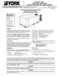
279815-PTG-D-0408
TECHNICAL
GUIDE
DESCRIPTION
SINGLE PACKAGE
COOLING UNITS
ACP024 THRU 060
2 THRU 5 TON (13 SEER)
These packaged cooling air conditioners are designed for
outdoor installation. Only utility and duct connections are
required at the point of installation.
Field-installed electric heater accessories are available to
provide electric heat combined with electric cooling.
STANDARD FEATURES / BENEFITS
OPERATING EFFICIENCY - All ACP units provide high
operating efficiencies and have a SEER up to 13.
ON SITE FLEXIBILITY - All model sizes share a common,
compact design cabinet with a single footprint. The installer has
the flexibility of setting one curb and placing the proper tonnage
unit on that curb after the internal load has been determined.
Field convertible duct connections from side shot to down shot
allows the installer to have greater flexibility and needs to carry
less inventory.
LOWER INSTALLATION COST - Installation time and costs
are reduced by easy power and control wiring connections. The
small base dimension means less space is required on the
ground or roof, plus, the installer can fit this unit between the
wheel wells of a full size pick-up truck. All models are well under
500 pounds.
All units are completely wired, charged with R-22 and tested
prior to shipment. Unique test stations using a new state of the
art computerized process system are used to insure product
quality. Refrigerant charge, and component part numbers are
verified via computers at installation. Vital run test statistics
such as system pressure, motor currents, air velocity and
temperature and unit vibration are monitored and recorded by
the system to insure unit performance.
Equal size, side supply and return duct connections allows easy
hook-up of ducts to match low crawl spaces without transition
pieces.
ISO 9001
Certified Quality
Management System
FOR DISTRIBUTION USE ONLY - NOT TO BE USED AT POINT OF RETAIL SALE
279815-PTG-D-0408
TABLE OF CONTENTS
LIST OF TABLES
DESCRIPTION . . . . . . . . . . . . . . . . . . . . . . . . . . . . . . . . . . .1
STANDARD FEATURES / BENEFITS . . . . . . . . . . . . . . . . .1
FIELD-INSTALLED ACCESSORIES . . . . . . . . . . . . . . . . . .3
Tbl. #
Pg. #
TYPICAL APPLICATIONS . . . . . . . . . . . . . . . . . . . . . . . . .24
1 PHYSICAL DATA . . . . . . . . . . . . . . . . . . . . . . . . . . . . . . 5
MECHANICAL SPECIFICATIONS . . . . . . . . . . . . . . . . . . .29
2 RATINGS - ARI . . . . . . . . . . . . . . . . . . . . . . . . . . . . . . . . 5
3 COOLING CAPACITIES - 2 TON (ACP024) . . . . . . . . . 6
LIST OF FIGURES
4 COOLING CAPACITIES - 2-1/2 TON (ACP030) . . . . . . 8
Fig. #
Pg. #
5 COOLING CAPACITIES - 3 TON (ACP036) . . . . . . . . 10
6 COOLING CAPACITIES - 3-1/2 TON (ACP042) . . . . . 12
1 UNIT CUTAWAY . . . . . . . . . . . . . . . . . . . . . . . . . . . . . . . 4
7 COOLING CAPACITIES - 4 TON (ACP048) . . . . . . . . 14
2 TYPICAL FIELD WIRING DIAGRAM . . . . . . . . . . . . . 19
8 COOLING CAPACITIES - 5 TON (ACP060) . . . . . . . . 16
3 UNIT DIMENSIONS . . . . . . . . . . . . . . . . . . . . . . . . . . 22
4 CENTER OF GRAVITY. . . . . . . . . . . . . . . . . . . . . . . . 23
9 SIDE AND BOTTOM SUPPLY AIR BLOWER
PERFORMANCE . . . . . . . . . . . . . . . . . . . . . . . . . . . . . 17
5 TYPICAL SLAB ON GROUND INSTALLATION. . . . . 24
10 ADDITIONAL STATIC RESISTANCE . . . . . . . . . . . . . 18
6 TYPICAL ROOF CURB INSTALLATION . . . . . . . . . . 24
11 ACP024-060 ELECTRICAL DATA / ELECTRIC
HEAT. . . . . . . . . . . . . . . . . . . . . . . . . . . . . . . . . . . . . . . 20
7 ROOF CURB DIMENSIONS (8” ROOF CURB
ALSO AVAILABLE) . . . . . . . . . . . . . . . . . . . . . . . . . . . . 25
12 UNIT WEIGHTS . . . . . . . . . . . . . . . . . . . . . . . . . . . . . . 23
8 ROOF CURB APPLICATION . . . . . . . . . . . . . . . . . . . 25
13 CLEARANCES . . . . . . . . . . . . . . . . . . . . . . . . . . . . . . . 23
9 TYPICAL WIRING DIAGRAM (208/230-1-60 POWER
SUPPLY) ACP MODELS . . . . . . . . . . . . . . . . . . . . . . . 26
10 TYPICAL WIRING DIAGRAM (208/230-3-60 POWER
SUPPLY) ACP MODELS . . . . . . . . . . . . . . . . . . . . . . . 27
11 TYPICAL WIRING DIAGRAM (460-3-60 POWER
SUPPLY) ACP MODELS . . . . . . . . . . . . . . . . . . . . . . . 28
PRODUCT NOMENCLATURE
A C P
0 2 4
C
1 3
2
2
IDENTIFIER
GENERATION
ACP = AIR CONDITIONER
PACKAGED
SEER
1 = 1ST
2 = 2ND
13 = 13 SEER
VOLTAGE CODE
COOLING CAPACITY
024 = 24,000 BTUH
036 = 36,000 BTUH
048 = 48,000 BTUH
2
030 = 30,000 BTUH
042 = 42,000 BTUH
060 = 60,000 BTUH
HEAT CODE
C = COOLING ONLY
2 = 208/230-1-60
3 = 208/230-3-60
4 = 460-3-60
Johnson Controls Unitary Products
279815-PTG-D-0408
DESCRIPTION (CONTINUED)
UTILITY CONNECTIONS MADE EASY - Electrical utility
knockouts are provided through the bottom as well as the side
of the unit. Utility connections can be made quickly and with a
minimum amount of field labor. A field supplied and field
installed electrical disconnect switch must be installed.
CONVERTIBLE AIRFLOW DESIGN - The bottom duct
openings are covered when they leave the factory ready to be
used for a side supply / side return application. If a bottom supply
/ bottom return application is desired, you simply remove the two
panels from the bottom of the unit and place them in the side
supply / side return duct openings. No panel cutting is required
and no accessory panel is necessary. Convertible airflow design
allows maximum field flexibility and minimum inventory.
CONDENSATE PAN - A non-corrosive, long-lasting, water-tight
pan is positioned below the evaporator coil to collect and drain
all condensate. Less collection of stagnate condensate will
build-up. The condensate pan conforms to ASHRAE 62-89
standards (Ventilation for Acceptable Indoor Air Quality).
CONDENSATE DRAIN - The heavy duty, inch NPTI copper
connection is more tolerable during installation and is more
durable over time. The connection is rigidly mounted to assure
proper fit and leak tight seal.
DURABLE FINISH - With a heavy duty cabinet made of powderpainted, galvanized steel the neutral color blends into
surrounding areas. The powered paint, provides a better paint to
steel bond, which resists corrosion and rust creep. The special
primer formulas and glossy earth tone finish insure less fading
when exposed to sunlight and offers a more attractive on site
appearance. This paint finish exceeds ASTM-B117 standards for
1000 hours salt spray rating, the highest in the industry.
FULL PERIMETER BASE RAILS - The easily removable base
rails provide a solid foundation for the entire unit and protects
the unit during shipment. The rails provide fork lift access from
all sides, and rigging holes are also provided so that an
overhead crane can be used to place the units on a roof. On
applications when the unit is placed on a pad, the base will
keep the unit off the pad to deter corrosion. On applications
where height is limited, the inch high base rails may be
removed on location.
MORE ATTRACTIVE APPEARANCE - A single piece “Water
Shed” top cover containing a top discharge condenser fan
arrangement requires less square footage on installation and
provides a wider variety of installations. The one piece design
adds greater water integrity. Rounded corners with water drip
edges add to the attractive appearance. The cabinet panels
have a non-fibrous insulation that does not add insulation fibers
into conditioned area.
TOP DISCHARGE - The top discharge condenser fan does not
disrupt neighboring areas and does not dry-out vegetation
surrounding the unit. The warm air from the top mounted fan is
blown up away from the structure and any landscaping. This
allows compact location on multi-unit applications.
Johnson Controls Unitary Products
CONDENSER COIL GRILLE - A multi-piece totally enclosed,
rigidly mounted condenser coil grille provides protection from
objects and personal after installation and provides protection
during transit and installation.
LOW OPERATING SOUND LEVEL - The upward air flow carries
the normal operating noise up and away from the living area. The
rigid top panel effectively isolates any motor sound. Isolator
mounted compressor and the rippled fins of the condenser coil
muffle the normal fan motor and compressor operating sounds.
The unique formed base pan also aids in sound alterations with it's
“Super-Structure” design. This design strategically places
embossments in the pan for optimum strength and rigidity.
FAN SYSTEM - All models operate over a wide range of design
conditions with a 5 speed direct drive indoor blower motor.
These units easily match all types of applications and provide
greater on site flexibility to match comfort requirements.
SIMPLE CONTROL CIRCUIT - A low voltage printed circuit
board contains a low voltage terminal strip. The electrical
control box is not located in the compressor compartment. All
wiring internal to the unit is color/number coded.
PROTECTED COMPRESSOR - The compressor is internally
protected against high pressure and temperature. This is
accomplished by the simultaneous operation of high pressure
relief valve and a temperature sensor which protect the
compressor if undesirable operating conditions occur.
EXCLUSIVE COIL DESIGN - Grooved copper tubes and
enhanced aluminum fin construction improves heat transfer for
maximum efficiency and durability.
LOW MAINTENANCE - Long life, permanently lubricated
condenser and evaporator fan motor bearings need no annual
maintenance adding greater reliability to the unit. Blower
assembly can be easily removed for cleaning by the unique
“Slip- Track” slide-out blower assembly.
SECURED SERVICE ACCESS PORTS - Protected, externally
mounted, re-usable service access ports are provided on both
the high and low lines for ease of evacuating and charging the
system. No final field mounting required.
EASY SERVICE ACCESS - A large, single panel covers the
electrical controls and makes servicing easy. The blower
compartment has an additional large panel with a built-in
handle tab. Removing this panel will allow the blower assembly
to slide-out for easy removal for maintenance and ease of
trouble shooting.
REPLACEMENT PARTS - The installer has no need to carry
an inventory of unique parts or needs special training to replace
any of the components parts for these units. All are easily
obtained from Source 1 or other part houses.
FIELD-INSTALLED ACCESSORIES
ECONOMIZER DOWN DISCHARGE / SUPPLY KIT Modulating integrated economizer provides simultaneous
operation between the mechanical cooling and economizer
3
279815-PTG-D-0408
operation. Independent blade design insures proper control and
less than 1% leak rate. Includes hood and mesh bird screen
filter integrated into the hood, dry bulb sensor and relief
damper. Separate field accessories of single enthalpy and dual
enthalpy are also available.
MOTORIZED FRESH AIR DAMPER - Designed for duct
mounted side supply/return and unit mounted down supply/
return applications. Damper capable of providing 0% thru 50%
of outdoor air (field supplied). Closes on power loss, includes
hood and screen assembly.
SINGLE ENTHALPY SENSOR - Sensor replaces dry bulb
sensor standard in economizer kit. Provides improved
economizer operation by sensing the dry bulb temperature from
outdoors plus the enthalpy content of the outdoor air.
RECTANGLE TO ROUND ADAPTERS - Kit includes one
supply and one return air rectangle to round duct adapter.
Adapters are preformed and designed to fit over current duct
openings on the base unit. Transition is from 15" square to 14"
round.
DUAL ENTHALPY SENSOR - Additional sensor to single
enthalpy sensor. Sensor senses both the return air temperature
dry bulb and humidity in conjunction with the single enthalpy to
determine the most economical mix. Single Enthalpy sensor
also required.
UPGRADE SAFETY PACKAGE - Contains screw in type High
pressure, Low Pressure/Loss of Charge switch, freeze protection
switch and lockout relay. Switches are placed onto existing
scharder ports located in the unit by furnished adapters. When
abnormal conditions are sensed through the pressure switches,
the unit will lock out preventing any further operation until reset or
problem is corrected. Package agency approved.
HAIL GUARD KIT - Kit contains protected grilles made of
expanded aluminum grilles with full perimeter inch frame.
Sloped hoods are also included to assure maximum protection.
ANTI SHORT CYCLE TIMER - Automatically prevents the
compressor from restarting for 5 minutes after cycled off. Not
required if Thermostat 2ET07700224 and 2ET04700224 are used.
FILTER / FRAME KIT (Single Phase only) - Kit contains the
necessary hardware to field install return air filters into the base
unit. Pre-cut filter racks and appropriate cleanable standard
size filters are shipped in one kit. (1" filter is supplied) This kit is
available for single phase horizontal or vertical duct application
only. Standard in all 3 Phase models.
ROOF CURBS - NRCA approved curbs provide proper fit to
base unit for rooftop installations. Curbs are designed to be
assembled through hinge pins in each corner. Kit also provides
seal strip to assure a water tight seal. 8 and 14 inch high roof
curbs are available.
MANUAL OUTDOOR DAMPER - Provides 0% thru 50%
outdoor air capability (field adjustable). Designed for duct
mounted side supply/return applications. Includes hood and
screen assembly.
WALL THERMOSTAT - The units are designed to operate with
24-volt electronic and electro-mechanical thermostats. All units
can operate with single stage heat / single stage cool
thermostats - with or without the economizer.
LOW AMBIENT KIT - Kit provides necessary hardware to
convert unit to operate in cooling cycle down to 0° F. Standard
unit operation 45° F.
TRANSFORMER KIT - Kit provides necessary hardware to
provide single phase models from factory furnished 40 VA
transformer capability to 75 VA transformer capability.
ELECTRIC HEATERS - Each heater package provides easy
installation of electric heat strips. Slide in design with plug in
harness and agency approved. Heaters are available from 5.0
KW sizes and are designed for single point connection.
DIRECT DRIVE
CONDENSER
FAN MOTOR
BACK AND BOTTOM
RETURN AIR
AND SUPPLY AIR
DUCT OPENING
HIGHLY EFFICIENT ENHANCED
COPPER TUBE/ALUMINUM FIN
EVAPORATOR COIL
HIGHLY EFFICIENT
ENHANCED COPPER
TUBE/ALUMINUM FIN
CONDENSER COIL
DECORATIVE
PROTECTIVE
COIL GUARD
HIGH VOLTAGE
TERMINAL BLOCK
LOW VOLTAGE
TERMINAL BLOCK
LONG LASTING
POWDER PAINT
FINISH EARTH
TONE COLOR HIGH EFFICIENCY
COMPRESSOR
RIGIDLY
MOUNTED
5-SPEED DIRECT DRIVE
BLOWER MOTOR WITH
SLIDE-OUT BLOWER ASSEMBLY
HEAVY GAUGE
REMOVABLE
BASE RAILS
FIGURE 1 - UNIT CUTAWAY
4
Johnson Controls Unitary Products
279815-PTG-D-0408
TABLE 1: PHYSICAL DATA
MODELS
EVAPORATOR CENTRIFUGAL BLOWER (Dia. x Wd. in.)
BLOWER
FAN MOTOR HP
ROWS DEEP
EVAPORATOR FINS PER INCH
FACE AREA (Sq. Ft.)
COIL
PROPELLER DIA. (in.)
CONDENSER FAN MOTOR HP
NOM. CFM TOTAL
FAN
ROWS DEEP
CONDENSER FINS PER INCH
FACE AREA (Sq. Ft.)
COIL
CHARGE
REFRIGERANT 22 (lbs./oz.)
FILTER
FACE AREA (Sq. Ft.) / Qty. / Size
COMPRESSOR HERMETIC, QTY. = 1 (Type)
024
10 x 8
½
2
15
4.38
22
¼
1,800
1
20
12.9
4/10
030
10 x 8
½
2
15
4.38
22
¼
1,800
1
20
12.9
5/9
Recip.
Rotary
ACP
036
042
10 x 8
11 x 10
3
½
4
3
3
13
16
4.38
4.38
22
22
¼
¼
1,800
2,400
1
1
20
20
12.9
12.9
5/0
4/12
2.14 / 1 / 14" x 22”
Scroll
Scroll
048
11 x 10
3
16
5.63
22
¼
3,000
1
20
16.4
6/0
060
11 x 10
1
3
16
5.63
22
½
3,000
2
20
16.4
10/8
Scroll
Scroll
3
4
TABLE 2: RATINGS - ARI
Model ACP
024
030
036
042
048
060
Cooling1
Capacity
80/67-95 °F
MBH
SEER
24.0
13.00
29.2
13.00
35.0
13.00
42.0
13.00
46.0
13.00
58.0
13.00
Sound Rating2
(decibels)
80
82
75
77
82
82
Electric Heat
Nom. Capacity
KW
(single phase)
5.0, 7.5, 10.0
5.0, 7.5, 10.0, 15.0
5.0, 7.5, 10.0, 15.0
5.0, 7.5, 10.0, 15.0
10.0, 15.0, 20.0, 25.0
10.0, 15.0, 20.0, 25.0
Electric Heat
Nom. Capacity
KW
(three phase)
N/A
N/A
10.0, 15.0
10.0, 15.0
10.0, 15.0, 20.0, 25.0
10.0, 15.0, 20.0, 25.0
1. Certified in accordance with the Unitary Small Equipment certification program, which is based on ARI Standard 210/240.
2. Rated in accordance with ARI Standard 270.
SEER = Seasonal Energy Efficiency Ratio - the total cooling output in BTU's during a normal annual usage period for cooling divided by the
total electric power input in watt-hours during the same period.
Johnson Controls Unitary Products
5
279815-PTG-D-0408
TABLE 3: COOLING CAPACITIES - 2 TON (ACP024)
Air on
Evaporator Coil
CFM
600
700
800
900
1000
600
700
800
900
1000
6
WB
(°F)
Total
Capacity1
(MBh)
Total
Input
(kW)2
90
77
72
67
62
57
77
72
67
62
57
77
72
67
62
57
72
67
62
57
72
67
62
57
27.1
26.8
26.4
25.5
24.5
27.2
26.9
26.6
25.6
24.7
27.3
27.0
26.7
25.7
24.8
27.1
26.8
25.8
24.9
27.2
26.9
25.9
25.0
1.7
1.7
1.7
1.7
1.7
1.7
1.7
1.7
1.7
1.7
1.7
1.7
1.7
1.7
1.7
1.8
1.8
1.8
1.8
1.8
1.8
1.8
1.8
12.1
16.7
21.3
24.5
24.5
12.0
17.6
22.8
24.7
24.7
11.9
18.4
24.8
24.8
24.8
19.0
24.9
24.9
24.9
19.6
25.0
25.0
25.0
77
72
67
62
57
77
72
67
62
57
77
72
67
62
57
72
67
62
57
72
67
62
57
26.3
24.9
23.4
22.2
20.9
26.6
25.1
23.7
22.4
21.2
26.9
25.4
23.9
22.7
21.4
25.7
24.2
22.9
21.6
25.9
24.4
23.1
21.8
2.1
2.1
2.0
2.0
2.0
2.2
2.1
2.1
2.0
2.0
2.2
2.1
2.1
2.1
2.0
2.1
2.1
2.1
2.1
2.2
2.1
2.1
2.1
12.2
16.3
20.4
20.9
20.9
14.5
17.7
21.2
21.2
21.2
16.8
19.1
21.4
21.4
21.4
20.4
21.6
21.6
21.6
21.7
21.8
21.8
21.8
Temperature of Air on Condenser Coil
Sensible Capacity (MBh)
Total
Total
Return Dry Bulb (°F)
Capacity1
Input
(MBh)
(kW)2
85
80
75
70
65
75°F
10.0
7.8
26.7
1.9
14.6
12.4
10.3
25.8
1.9
19.2
17.0
14.9
12.7
24.9
1.9
22.9
20.8
18.6
16.5
14.3
23.8
1.9
24.5
24.5
20.8
18.7
16.5
22.7
1.9
10.4
8.1
26.9
1.9
15.2
12.9
10.6
26.0
1.9
20.0
17.7
15.4
13.0
25.1
1.9
23.4
21.6
19.5
17.0
14.6
24.0
1.9
24.7
24.7
21.8
19.2
16.9
22.9
1.9
10.9
8.4
27.1
2.0
15.9
13.4
10.9
26.2
1.9
20.9
18.4
15.9
13.4
25.3
1.9
24.8
22.4
20.3
17.4
14.9
24.2
1.9
24.8
24.8
22.7
19.8
17.3
23.1
1.9
16.4
13.9
11.3
26.4
2.0
21.9
19.0
16.5
13.9
25.5
1.9
24.9
23.5
21.2
18.4
15.8
24.4
1.9
24.9
24.8
22.5
19.8
17.2
23.2
1.9
17.0
14.4
11.7
26.6
2.0
23.8
19.7
17.1
14.4
25.7
2.0
25.0
24.6
22.0
19.4
16.7
24.5
1.9
25.0
25.0
22.3
19.7
17.1
23.4
1.9
95°F
9.7
7.1
24.6
2.3
13.8
11.2
8.7
22.6
2.3
17.9
15.3
12.8
10.2
20.6
2.2
20.0
17.4
14.9
12.4
9.8
19.8
2.2
20.9
18.8
16.3
13.7
11.2
19.0
2.1
10.5
7.6
25.0
2.4
14.8
12.0
9.1
23.0
2.3
19.2
16.4
13.5
10.7
21.0
2.2
21.2
18.6
15.6
12.9
10.1
20.1
2.2
21.2
20.1
17.1
14.4
11.5
19.3
2.2
11.3
8.1
25.4
2.4
15.9
12.8
9.6
23.3
2.3
20.6
17.4
14.3
11.1
21.3
2.2
21.4
19.8
16.3
13.5
10.3
20.4
2.2
21.4
21.4
17.9
15.1
11.9
19.6
2.2
17.0
13.6
10.1
23.7
2.3
21.6
18.5
15.1
11.7
21.6
2.2
21.6
20.8
17.2
14.0
10.6
20.7
2.2
21.6
21.6
18.0
14.8
11.4
19.9
2.2
18.0
14.4
10.7
24.1
2.3
21.8
19.6
15.9
12.3
21.9
2.3
21.8
21.8
18.1
14.5
10.8
21.0
2.3
21.8
21.8
18.2
14.5
10.9
20.2
2.2
90
12.2
16.5
20.9
22.7
22.7
13.3
17.6
22.0
22.9
22.9
14.4
18.7
23.1
23.1
23.1
19.7
23.2
23.2
23.2
20.7
23.4
23.4
23.4
11.8
15.7
18.7
19.0
19.0
14.5
17.0
19.3
19.3
19.3
17.2
18.4
19.6
19.6
19.6
19.9
19.9
19.9
19.9
20.2
20.2
20.2
20.2
Sensible Capacity (MBh)
Return Dry Bulb (°F)
85
80
75
70
85°F
9.8
7.5
14.2
11.8
9.5
18.5
16.2
13.8
11.5
21.5
19.1
16.8
14.4
22.7
20.9
18.5
16.2
10.5
7.9
15.0
12.4
9.9
19.6
17.0
14.4
11.9
22.3
20.1
17.5
14.9
22.9
22.0
19.4
16.8
11.1
8.3
15.9
13.1
10.2
20.7
17.9
15.1
12.2
23.1
21.1
18.3
15.5
23.1
23.1
20.3
17.4
16.7
13.7
10.7
21.8
18.8
15.8
12.8
23.2
22.2
19.2
16.2
23.2
23.2
20.3
17.3
17.5
14.4
11.2
22.8
19.7
16.5
13.3
23.4
23.2
20.1
16.9
23.4
23.4
20.3
17.1
105°F
9.2
6.5
13.0
10.4
7.8
16.9
14.3
11.6
9.0
18.5
15.8
13.2
10.6
19.0
16.9
14.3
11.7
10.4
7.0
14.2
11.2
8.2
18.0
15.4
12.4
9.4
19.0
17.1
14.0
11.1
19.3
18.2
15.2
12.3
11.6
7.6
15.4
12.0
8.7
19.1
16.5
13.1
9.8
19.6
18.3
14.7
11.6
19.6
19.6
16.0
12.8
16.5
12.9
9.2
19.9
17.6
14.0
10.3
19.9
19.2
15.4
11.9
19.9
19.9
16.1
12.5
17.7
13.7
9.7
20.2
18.8
14.8
10.8
20.2
20.2
16.1
12.2
20.2
20.2
16.2
12.2
65
12.1
13.8
12.4
14.2
12.6
14.6
13.2
14.3
13.8
14.0
7.9
9.1
8.1
9.3
8.2
9.5
8.2
8.8
8.2
8.2
Johnson Controls Unitary Products
279815-PTG-D-0408
TABLE 3: COOLING CAPACITIES - 2 TON (ACP024) (CONTINUED)
Air on
Evaporator Coil
CFM
600
700
800
900
1000
WB
(°F)
Total
Capacity1
(MBh)
Total
Input
(kW)2
90
77
72
67
62
57
77
72
67
62
57
77
72
67
62
57
72
67
62
57
72
67
62
57
22.9
20.4
17.8
17.4
17.0
23.4
20.8
18.2
17.8
17.3
23.9
21.3
18.6
18.2
17.7
21.7
19.0
18.6
18.1
22.2
19.4
19.0
18.5
2.5
2.4
2.3
2.3
2.3
2.6
2.5
2.3
2.3
2.3
2.6
2.5
2.4
2.4
2.3
2.5
2.4
2.4
2.4
2.5
2.4
2.4
2.4
11.4
15.0
17.0
17.0
17.0
14.5
16.4
17.3
17.3
17.3
17.7
17.7
17.7
17.7
17.7
18.1
18.1
18.1
18.1
18.5
18.5
18.5
18.5
Temperature of Air on Condenser Coil
Sensible Capacity (MBh)
Total
Total
Return Dry Bulb (°F)
Capacity1
Input
(MBh)
(kW)2
85
80
75
70
65
115°F
8.7
6.0
21.2
2.7
12.3
9.6
6.9
18.1
2.6
16.0
13.2
10.5
7.8
15.1
2.5
16.9
14.2
11.5
8.8
6.1
15.0
2.4
17.0
15.1
12.4
9.6
6.9
15.0
2.4
10.3
6.5
21.8
2.8
13.6
10.4
7.3
18.7
2.6
16.8
14.4
11.3
8.1
15.5
2.5
17.3
15.5
12.3
9.2
6.1
15.5
2.5
17.3
16.4
13.3
10.1
7.0
15.4
2.5
11.9
7.0
22.5
2.8
14.8
11.3
7.7
19.2
2.7
17.7
15.5
12.0
8.5
16.0
2.5
17.7
16.7
13.2
9.6
6.1
15.9
2.5
17.7
17.7
14.2
10.6
7.1
15.9
2.5
16.1
12.2
8.2
19.8
2.7
18.1
16.8
12.8
8.9
16.5
2.5
18.1
17.6
13.6
9.7
5.8
16.4
2.5
18.1
18.1
14.1
10.2
6.3
16.3
2.5
17.4
13.1
8.7
20.3
2.7
18.5
18.0
13.7
9.3
16.9
2.6
18.5
18.5
14.1
9.8
5.5
16.9
2.6
18.5
18.5
14.1
9.8
5.5
16.8
2.5
90
11.0
14.4
15.0
15.0
15.0
13.4
15.3
15.3
15.3
15.4
15.8
15.8
15.8
15.8
15.9
16.3
16.3
16.3
16.3
16.8
16.8
16.8
16.8
Sensible Capacity (MBh)
Return Dry Bulb (°F)
85
80
75
70
125°F
8.2
5.4
11.6
8.8
6.0
15.0
12.2
9.4
6.6
15.0
12.6
9.8
7.0
15.0
13.2
10.4
7.6
10.2
5.9
12.9
9.7
6.4
15.3
13.4
10.1
6.9
15.3
13.9
10.7
7.3
15.4
14.5
11.4
8.0
12.3
6.5
14.3
10.5
6.8
15.8
14.6
10.9
7.1
15.8
15.1
11.6
7.7
15.9
15.9
12.3
8.4
15.7
11.5
7.3
16.3
15.9
11.7
7.5
16.3
16.0
11.8
7.6
16.3
16.3
12.2
7.9
17.1
12.4
7.7
16.8
16.8
12.1
7.9
16.8
16.8
12.1
7.5
16.8
16.8
12.1
7.5
65
4.2
4.8
4.1
4.7
3.9
4.6
3.4
3.7
2.8
2.8
1. These capacities are Net Capacities.
2. These ratings include the compressor, condenser fan and supply air blower motors.
Johnson Controls Unitary Products
7
279815-PTG-D-0408
TABLE 4: COOLING CAPACITIES - 2-1/2 TON (ACP030)
Air on
Evaporator Coil
CFM
750
875
1000
1125
1250
750
875
1000
1125
1250
8
WB
(°F)
Total
Capacity1
(MBh)
Total
Input
(kW)2
90
77
72
67
62
57
77
72
67
62
57
77
72
67
62
57
72
67
62
57
72
67
62
57
33.1
32.5
31.9
31.1
31.0
33.3
32.7
32.1
31.3
31.2
33.5
32.9
32.3
31.5
31.4
33.2
32.5
31.8
31.6
33.4
32.8
32.0
31.8
2.0
2.1
2.2
2.0
2.0
2.0
2.1
2.2
2.0
2.0
2.0
2.1
2.2
2.1
2.0
2.1
2.2
2.1
2.0
2.1
2.2
2.1
2.0
14.8
19.9
25.0
31.0
31.0
15.2
21.0
26.7
31.2
31.2
15.7
22.1
28.5
31.4
31.4
23.1
30.3
31.6
31.6
24.0
31.8
31.8
31.8
77
72
67
62
57
77
72
67
62
57
77
72
67
62
57
72
67
62
57
72
67
62
57
31.8
30.3
28.8
27.0
27.3
32.0
30.5
29.0
27.2
27.5
32.3
30.8
29.2
27.4
27.7
31.0
29.5
27.6
27.9
31.2
29.7
27.9
28.1
2.5
2.5
2.4
2.4
2.3
2.5
2.5
2.5
2.4
2.4
2.5
2.5
2.5
2.4
2.4
2.5
2.5
2.4
2.4
2.6
2.6
2.5
2.4
14.8
19.8
24.8
27.0
27.3
16.5
21.3
26.1
27.2
27.5
18.2
22.8
27.4
27.4
27.7
24.2
27.6
27.6
27.9
25.5
27.9
27.9
28.1
Temperature of Air on Condenser Coil
Sensible Capacity (MBh)
Total
Total
Return Dry Bulb (°F)
Capacity1
Input
(MBh)
(kW)2
85
80
75
70
65
75°F
12.2
9.6
32.4
2.3
17.3
14.7
12.1
31.4
2.3
22.4
19.8
17.2
14.7
30.3
2.3
28.5
25.9
23.3
20.8
18.2
29.0
2.2
30.4
27.9
25.3
22.7
20.2
29.1
2.2
12.8
10.0
32.7
2.3
18.2
15.3
12.5
31.6
2.3
23.5
20.6
17.8
15.0
30.6
2.3
30.0
27.0
24.4
21.3
18.5
29.3
2.2
30.9
29.1
26.6
23.4
20.6
29.3
2.2
13.5
10.4
32.9
2.3
19.0
15.9
12.9
31.8
2.3
24.5
21.5
18.4
15.3
30.8
2.3
31.4
28.1
25.5
21.9
18.8
29.5
2.2
31.4
30.2
27.8
24.1
21.0
29.6
2.2
19.8
16.6
13.3
32.1
2.3
25.5
22.3
19.1
15.8
31.0
2.4
31.6
29.8
26.8
23.3
20.1
29.7
2.2
31.6
31.0
28.1
24.5
21.3
29.8
2.2
20.6
17.2
13.8
32.3
2.3
26.5
23.1
19.7
16.3
31.2
2.4
31.8
31.6
28.2
24.7
21.3
29.9
2.3
31.8
31.8
28.4
25.0
21.6
30.0
2.2
95°F
11.8
8.8
30.8
2.7
16.8
13.7
10.7
28.8
2.6
21.7
18.7
15.7
12.7
26.8
2.6
26.9
23.9
20.8
17.8
14.8
25.3
2.5
27.2
24.2
21.1
18.1
15.1
25.6
2.5
12.6
9.2
30.7
2.7
17.9
14.5
11.1
28.7
2.7
23.1
19.7
16.3
12.9
26.7
2.6
27.2
25.2
21.5
18.3
14.9
25.2
2.6
27.4
25.5
21.7
18.7
15.3
25.5
2.6
13.5
9.7
30.5
2.8
19.0
15.2
11.5
28.5
2.7
24.5
20.7
17.0
13.2
26.6
2.7
27.4
26.4
22.1
18.9
15.1
25.1
2.6
27.7
26.8
22.3
19.2
15.4
25.4
2.6
20.1
16.0
11.9
28.4
2.7
25.9
21.8
17.7
13.6
26.5
2.7
27.6
27.2
22.8
19.0
14.9
25.0
2.6
27.9
27.5
23.0
19.3
15.2
25.3
2.6
21.2
16.8
12.4
28.3
2.8
27.2
22.9
18.5
14.1
26.4
2.7
27.9
27.9
23.5
19.1
14.7
24.9
2.7
28.1
28.1
23.8
19.4
15.0
25.2
2.7
90
14.8
19.8
24.9
29.0
29.1
15.9
21.1
26.4
29.3
29.3
16.9
22.4
28.0
29.5
29.6
23.6
28.9
29.7
29.8
24.8
29.9
29.9
30.0
14.3
19.1
23.8
25.3
25.6
17.0
20.7
24.5
25.2
25.5
19.6
22.4
25.1
25.1
25.4
23.6
25.0
25.0
25.3
24.9
24.9
24.9
25.2
Sensible Capacity (MBh)
Return Dry Bulb (°F)
85
80
75
70
85°F
12.0
9.2
17.0
14.2
11.4
22.1
19.3
16.5
13.7
27.7
24.9
22.1
19.3
28.8
26.0
23.2
20.4
12.7
9.6
18.0
14.9
11.8
23.3
20.2
17.1
14.0
28.6
26.1
23.0
19.8
29.2
27.3
24.1
21.0
13.5
10.1
19.0
15.6
12.2
24.5
21.1
17.7
14.2
29.5
27.3
23.8
20.4
29.6
28.5
25.1
21.6
19.9
16.3
12.6
25.7
22.1
18.4
14.7
29.7
28.5
24.8
21.2
29.8
29.2
25.6
21.9
20.9
17.0
13.1
26.9
23.0
19.1
15.2
29.9
29.7
25.8
21.9
30.0
30.0
26.1
22.2
105°F
11.2
8.1
15.9
12.8
9.7
20.7
17.6
14.5
11.4
24.9
21.8
18.7
15.6
24.9
21.8
18.7
15.6
12.2
8.6
17.2
13.7
10.1
22.2
18.7
15.2
11.7
25.0
23.2
19.5
16.1
25.2
23.2
19.5
16.2
13.2
9.1
18.4
14.5
10.5
23.7
19.8
15.9
11.9
25.1
24.5
20.3
16.6
25.4
24.6
20.3
16.7
20.0
15.3
10.9
24.3
20.9
16.6
12.3
25.0
24.7
20.3
16.1
25.3
24.9
20.4
16.2
21.5
16.1
11.4
24.9
22.0
17.3
12.6
24.9
24.9
20.2
15.5
25.2
25.2
20.5
15.8
65
16.5
17.6
16.7
17.9
17.0
18.2
17.5
18.3
18.0
18.3
12.5
12.5
12.6
12.6
12.7
12.7
11.7
11.9
10.8
11.1
Johnson Controls Unitary Products
279815-PTG-D-0408
TABLE 4: COOLING CAPACITIES - 2-1/2 TON (ACP030) (CONTINUED)
Air on
Evaporator Coil
CFM
750
875
1000
1125
1250
WB
(°F)
Total
Capacity1
(MBh)
Total
Input
(kW)2
90
77
72
67
62
57
77
72
67
62
57
77
72
67
62
57
72
67
62
57
72
67
62
57
29.8
27.3
24.8
23.6
24.0
29.3
26.8
24.4
23.2
23.5
28.7
26.3
23.9
22.8
23.1
25.8
23.5
22.3
22.7
25.3
23.0
21.9
22.2
2.9
2.8
2.8
2.7
2.7
2.9
2.9
2.8
2.7
2.8
3.0
2.9
2.9
2.8
2.8
3.0
2.9
2.8
2.8
3.0
2.9
2.9
2.9
13.7
18.3
22.9
23.6
24.0
17.4
20.1
23.2
23.2
23.5
21.1
21.9
22.8
22.8
23.1
22.3
22.3
22.3
22.7
21.9
21.9
21.9
22.2
Temperature of Air on Condenser Coil
Sensible Capacity (MBh)
Total
Total
Return Dry Bulb (°F)
Capacity1
Input
(MBh)
(kW)2
85
80
75
70
65
115°F
10.6
7.4
28.8
3.1
15.1
11.9
8.8
25.8
3.0
19.7
16.5
13.3
10.1
22.8
2.9
22.9
19.7
16.6
13.4
10.2
22.0
2.9
22.7
19.5
16.4
13.2
10.0
22.3
2.9
11.7
7.9
27.9
3.1
16.5
12.8
9.2
25.0
3.1
21.2
17.7
14.1
10.4
22.1
3.0
22.8
21.2
17.5
13.9
10.2
21.2
2.9
22.9
21.0
17.3
13.7
10.0
21.5
3.0
12.8
8.5
27.0
3.2
17.8
13.7
9.6
24.1
3.1
22.8
18.9
14.8
10.7
21.3
3.0
22.8
22.6
18.5
14.4
10.2
20.4
3.0
23.1
22.4
18.3
14.1
10.0
20.8
3.0
19.9
14.5
9.9
23.2
3.2
22.3
20.0
15.5
10.9
20.5
3.1
22.3
22.3
17.7
13.1
8.6
19.7
3.0
22.7
22.7
17.7
13.2
8.6
20.0
3.0
21.9
15.3
10.3
22.4
3.2
21.9
21.2
16.1
11.1
19.7
3.1
21.9
21.9
16.9
11.9
6.9
18.9
3.1
22.2
22.2
17.2
12.2
7.2
19.3
3.1
90
13.2
17.6
21.9
22.0
22.3
16.8
19.5
21.2
21.2
21.5
20.4
20.4
20.4
20.4
20.8
19.6
19.6
19.7
20.0
18.9
18.9
18.9
19.3
Sensible Capacity (MBh)
Return Dry Bulb (°F)
85
80
75
70
125°F
10.0
6.7
14.3
11.1
7.8
18.6
15.4
12.1
8.9
20.9
17.7
14.4
11.2
20.5
17.2
14.0
10.7
11.2
7.3
15.8
12.0
8.2
20.3
16.7
12.9
9.1
20.7
19.2
15.5
11.6
20.6
18.7
15.1
11.2
12.5
7.9
17.2
12.9
8.6
20.4
18.0
13.7
9.4
20.4
20.4
16.7
12.1
20.8
20.8
16.2
11.6
19.6
13.8
8.9
19.6
19.1
14.3
9.5
19.7
19.7
15.1
10.2
20.0
20.0
15.1
10.1
18.9
14.6
9.3
18.9
18.9
15.0
9.7
18.9
18.9
13.6
8.3
19.3
19.3
13.9
8.6
65
7.9
7.5
7.9
7.4
7.8
7.3
5.4
5.3
3.0
3.3
1. These capacities are Net Capacities.
2. These ratings include the compressor, condenser fan and supply air blower motors.
Johnson Controls Unitary Products
9
279815-PTG-D-0408
TABLE 5: COOLING CAPACITIES - 3 TON (ACP036)
Air on
Evaporator Coil
CFM
1000
1125
1250
1375
1500
1000
1125
1250
1375
1500
10
WB
(°F)
Total
Capacity1
(MBh)
Total
Input
(kW)2
90
77
72
67
62
57
77
72
67
62
57
77
72
67
62
57
72
67
62
57
72
67
62
57
45.2
43.3
41.4
38.0
35.6
45.8
43.9
42.0
38.5
36.0
46.4
44.5
42.5
39.1
36.5
44.9
42.9
39.4
36.9
45.2
43.3
39.7
37.2
2.8
2.7
2.5
2.4
2.5
2.9
2.8
2.6
2.5
2.7
3.1
2.9
2.7
2.6
2.8
3.0
2.8
2.7
2.8
3.0
2.8
2.7
2.9
21.4
27.6
33.7
38.0
35.6
23.7
30.3
36.9
38.5
36.0
26.0
33.1
40.2
39.1
36.5
35.3
41.7
39.4
36.9
37.4
43.3
39.7
37.2
77
72
67
62
57
77
72
67
62
57
77
72
67
62
57
72
67
62
57
72
67
62
57
42.6
38.9
35.1
31.8
31.2
43.7
39.9
36.0
32.7
31.9
44.8
40.8
36.9
33.5
32.7
41.3
37.3
33.8
33.1
41.7
37.6
34.1
33.4
3.1
3.1
3.1
3.0
2.9
3.2
3.2
3.2
3.0
3.0
3.2
3.2
3.2
3.0
3.0
3.3
3.3
3.1
3.0
3.3
3.3
3.1
3.1
20.5
26.3
32.0
31.8
31.2
22.6
28.6
34.5
32.7
31.9
24.8
30.9
36.9
33.5
32.7
33.1
37.3
33.8
33.1
35.4
37.6
34.1
33.4
Temperature of Air on Condenser Coil
Sensible Capacity (MBh)
Total
Total
Return Dry Bulb (°F)
Capacity1
Input
(MBh)
(kW)2
85
80
75
70
65
75°F
17.8
14.2
43.9
3.0
24.0
20.4
16.7
41.1
2.9
30.1
26.5
22.9
19.3
38.3
2.8
36.7
31.8
28.2
24.6
21.0
34.9
2.7
35.6
35.2
31.6
28.0
24.4
33.4
2.7
19.4
14.9
44.8
3.1
25.8
21.3
16.8
41.9
3.0
32.2
27.7
23.2
18.7
39.0
2.9
37.9
32.9
28.6
23.9
19.4
35.6
2.8
36.0
35.9
31.6
26.9
22.4
34.0
2.8
21.0
15.6
45.6
3.1
27.7
22.3
16.9
42.7
3.1
34.4
29.0
23.6
18.1
39.7
3.0
39.1
34.0
29.0
23.2
17.8
36.3
2.8
36.5
36.5
31.7
25.7
20.3
34.6
2.9
29.4
23.6
17.7
43.1
3.1
36.5
30.7
24.8
19.0
40.1
3.0
39.4
36.9
31.2
25.2
19.3
36.6
2.9
36.9
36.9
31.3
25.2
19.3
35.0
2.9
31.2
24.9
18.6
43.5
3.1
38.6
32.4
26.1
19.8
40.5
3.1
39.7
39.7
33.4
27.2
20.9
36.9
2.9
37.2
37.2
30.9
24.6
18.3
35.3
3.0
95°F
16.7
12.8
39.3
3.4
22.4
18.6
14.8
35.7
3.3
28.2
24.4
20.6
16.8
32.2
3.3
31.8
29.4
25.6
21.7
17.9
29.3
3.1
31.2
30.9
27.1
23.3
19.5
28.8
3.1
18.0
13.6
40.2
3.4
24.1
19.7
15.2
36.6
3.4
30.2
25.8
21.3
16.9
33.0
3.4
32.7
31.4
26.8
22.5
18.1
29.9
3.2
31.9
31.8
27.1
22.9
18.5
29.5
3.2
19.3
14.3
41.1
3.5
25.8
20.7
15.6
37.4
3.5
32.2
27.1
22.0
17.0
33.7
3.4
33.5
33.5
28.0
23.3
18.2
30.6
3.3
32.7
32.7
27.1
22.6
17.5
30.2
3.3
27.4
21.8
16.1
37.8
3.5
34.2
28.5
22.8
17.1
34.0
3.5
33.8
33.8
27.9
22.4
16.7
30.9
3.3
33.1
33.1
27.1
21.7
16.0
30.5
3.3
29.1
22.8
16.5
38.1
3.6
36.2
29.9
23.6
17.3
34.4
3.5
34.1
34.1
27.8
21.6
15.3
31.2
3.4
33.4
33.4
27.1
20.8
14.5
30.8
3.3
90
21.0
26.9
32.9
34.9
33.4
23.2
29.4
35.7
35.6
34.0
25.4
32.0
38.5
36.3
34.6
34.2
39.5
36.6
35.0
36.4
40.5
36.9
35.3
19.2
24.7
30.3
29.3
28.8
23.0
27.5
32.0
29.9
29.5
26.9
30.3
33.7
30.6
30.2
32.1
34.0
30.9
30.5
33.9
34.4
31.2
30.8
Sensible Capacity (MBh)
Return Dry Bulb (°F)
85
80
75
70
85°F
17.2
13.5
23.2
19.5
15.8
29.1
25.4
21.7
18.0
34.3
30.6
26.9
23.2
33.4
33.1
29.4
25.6
18.7
14.2
25.0
20.5
16.0
31.2
26.7
22.3
17.8
35.3
32.2
27.7
23.2
34.0
33.9
29.4
24.9
20.2
14.9
26.7
21.5
16.2
33.3
28.0
22.8
17.6
36.3
33.7
28.5
23.2
34.6
34.6
29.4
24.1
28.4
22.7
16.9
35.4
29.6
23.8
18.1
36.6
35.3
29.6
23.8
35.0
35.0
29.2
23.4
30.1
23.8
17.6
37.4
31.1
24.8
18.5
36.9
36.9
30.6
24.4
35.3
35.3
29.0
22.7
105°F
15.5
11.9
21.1
17.4
13.8
26.7
23.0
19.3
15.7
29.3
28.2
24.5
20.8
28.8
28.7
25.0
21.4
17.1
12.6
23.1
18.6
14.1
29.0
24.5
20.1
15.6
29.9
29.4
24.8
20.4
29.5
29.4
24.8
20.5
18.7
13.4
25.0
19.7
14.5
31.3
26.1
20.8
15.5
30.6
30.6
25.1
20.0
30.2
30.2
24.6
19.6
26.4
20.6
14.8
32.5
27.2
21.4
15.6
30.9
30.9
25.1
19.4
30.5
30.5
24.6
18.9
27.7
21.4
15.2
33.6
28.3
22.0
15.8
31.2
31.2
25.0
18.7
30.8
30.8
24.5
18.3
65
19.5
21.9
18.7
20.4
18.0
18.9
18.0
17.7
18.1
16.4
17.2
17.7
16.0
16.0
14.8
14.3
13.6
13.2
12.5
12.0
Johnson Controls Unitary Products
279815-PTG-D-0408
TABLE 5: COOLING CAPACITIES - 3 TON (ACP036) (CONTINUED)
Air on
Evaporator Coil
CFM
1000
1125
1250
1375
1500
WB
(°F)
Total
Capacity1
(MBh)
Total
Input
(kW)2
90
77
72
67
62
57
77
72
67
62
57
77
72
67
62
57
72
67
62
57
72
67
62
57
36.0
32.6
29.3
26.7
26.5
36.7
33.3
29.9
27.2
27.1
37.4
34.0
30.5
27.8
27.6
34.3
30.8
28.0
27.9
34.6
31.1
28.3
28.2
3.6
3.5
3.4
3.3
3.3
3.7
3.6
3.5
3.4
3.4
3.8
3.7
3.6
3.5
3.5
3.8
3.7
3.6
3.6
3.8
3.7
3.6
3.6
17.9
23.2
28.6
26.7
26.5
23.4
26.5
29.5
27.2
27.1
29.0
29.8
30.5
27.8
27.6
31.1
30.8
28.0
27.9
32.5
31.1
28.3
28.2
Temperature of Air on Condenser Coil
Sensible Capacity (MBh)
Total
Total
Return Dry Bulb (°F)
Capacity1
Input
(MBh)
(kW)2
85
80
75
70
65
115°F
14.4
10.9
32.6
3.9
19.7
16.2
12.8
29.5
3.8
25.1
21.6
18.1
14.6
26.4
3.6
26.7
26.9
23.4
20.0
16.5
24.1
3.5
26.5
26.4
23.0
19.5
16.0
24.2
3.6
16.2
11.7
33.2
4.0
22.0
17.5
13.0
30.0
3.9
27.8
23.3
18.8
14.3
26.8
3.7
27.2
27.4
22.9
18.4
13.9
24.5
3.6
27.1
27.0
22.5
18.1
13.6
24.6
3.7
18.1
12.6
33.7
4.1
24.3
18.8
13.3
30.5
4.0
30.5
25.0
19.5
14.0
27.3
3.8
27.8
27.8
22.3
16.8
11.3
24.9
3.8
27.6
27.6
22.1
16.6
11.1
25.1
3.8
25.3
19.4
13.6
30.8
4.0
30.8
25.8
20.0
14.1
27.6
3.9
28.0
28.0
22.2
16.3
10.5
25.2
3.8
27.9
27.9
22.0
16.2
10.3
25.3
3.8
26.3
20.1
13.8
31.1
4.1
31.1
26.7
20.5
14.2
27.8
3.9
28.3
28.3
22.1
15.9
9.6
25.4
3.8
28.2
28.2
21.9
15.7
9.5
25.5
3.9
90
16.6
21.7
26.4
24.1
24.2
23.8
25.5
26.8
24.5
24.6
31.1
29.2
27.3
24.9
25.1
30.1
27.6
25.2
25.3
31.1
27.8
25.4
25.5
Sensible Capacity (MBh)
Return Dry Bulb (°F)
85
80
75
70
125°F
13.2
9.9
18.4
15.1
11.7
23.5
20.2
16.9
13.6
24.1
24.1
22.4
19.1
24.2
24.2
20.9
17.6
15.3
10.8
20.9
16.4
11.9
26.6
22.1
17.5
13.0
24.5
24.5
20.9
16.3
24.6
24.6
20.3
15.6
17.4
11.7
23.5
17.8
12.1
27.3
23.9
18.2
12.5
24.9
24.9
19.4
13.5
25.1
25.1
19.6
13.7
24.2
18.3
12.3
27.6
24.5
18.5
12.6
25.2
25.2
19.3
13.3
25.3
25.3
19.5
13.4
24.9
18.7
12.5
27.8
25.1
18.9
12.7
25.4
25.4
19.2
13.0
25.5
25.5
19.4
13.2
65
15.7
14.2
11.8
11.1
7.8
8.0
7.3
7.5
6.8
7.0
1. These capacities are Net Capacities.
2. These ratings include the compressor, condenser fan and supply air blower motors.
Johnson Controls Unitary Products
11
279815-PTG-D-0408
TABLE 6: COOLING CAPACITIES - 3-1/2 TON (ACP042)
Air on
Evaporator Coil
CFM
1050
1175
1300
1400
1500
1050
1175
1300
1400
1500
12
WB
(°F)
Total
Capacity1
(MBh)
Total
Input
(kW)2
90
77
72
67
62
57
77
72
67
62
57
77
72
67
62
57
72
67
62
57
72
67
62
57
51.5
48.4
45.3
42.5
41.6
51.7
48.6
45.5
42.6
41.8
51.9
48.8
45.6
42.8
41.9
49.1
45.9
43.0
42.2
49.4
46.2
43.3
42.5
3.0
3.0
2.9
2.9
2.8
3.0
3.0
2.9
2.9
2.8
3.1
3.0
3.0
2.9
2.8
3.1
3.0
3.0
2.9
3.1
3.1
3.1
3.0
23.9
30.8
37.6
41.6
41.6
24.1
31.9
39.2
41.8
41.8
24.4
33.1
41.9
41.9
41.9
34.3
42.7
42.2
42.2
35.5
42.5
42.5
42.5
77
72
67
62
57
77
72
67
62
57
77
72
67
62
57
72
67
62
57
72
67
62
57
47.9
44.2
40.6
36.7
37.2
48.0
44.4
40.8
36.9
37.4
48.2
44.6
40.9
37.0
37.5
44.9
41.3
37.3
37.8
45.3
41.6
37.6
38.1
3.8
3.7
3.6
3.5
3.5
3.8
3.7
3.6
3.6
3.5
3.8
3.8
3.7
3.6
3.5
3.8
3.7
3.7
3.6
3.9
3.8
3.7
3.7
22.6
29.1
35.7
36.7
37.2
24.6
30.5
36.9
36.9
37.4
26.6
31.8
37.0
37.0
37.5
33.3
37.3
37.3
37.8
34.8
37.6
37.6
38.1
Temperature of Air on Condenser Coil
Sensible Capacity (MBh)
Total
Total
Return Dry Bulb (°F)
Capacity1
Input
(MBh)
(kW)2
85
80
75
70
65
75°F
19.9
16.0
49.7
3.4
26.8
22.8
18.8
46.3
3.3
33.6
29.7
25.7
21.7
43.0
3.3
41.6
37.1
33.2
29.2
25.2
39.6
3.2
41.6
39.4
35.4
31.5
27.5
39.4
3.1
20.6
16.2
49.9
3.4
27.6
23.2
18.8
46.5
3.4
34.5
30.2
25.8
21.4
43.1
3.3
41.8
37.7
33.6
29.0
24.6
39.8
3.2
41.8
40.1
36.0
31.3
26.9
39.6
3.2
21.3
16.5
50.0
3.4
28.3
23.6
18.8
46.7
3.4
35.4
30.7
25.9
21.1
43.3
3.3
41.9
38.4
34.1
28.8
24.0
39.9
3.3
41.9
40.7
36.6
31.2
26.4
39.7
3.2
29.3
24.4
19.4
47.0
3.5
36.6
31.7
26.7
21.7
43.6
3.4
42.2
40.2
35.5
30.3
25.3
40.2
3.3
42.2
41.6
37.0
31.7
26.7
40.0
3.3
30.3
25.1
20.0
47.3
3.5
37.8
32.7
27.5
22.4
43.9
3.5
42.5
42.0
36.9
31.7
26.6
40.5
3.4
42.5
42.5
37.3
32.1
27.0
40.3
3.3
95°F
18.4
14.3
45.4
4.2
25.0
20.9
16.8
41.7
4.1
31.6
27.5
23.4
19.3
37.9
4.0
36.7
34.1
30.0
25.9
21.8
34.4
3.9
37.2
35.1
31.0
26.9
22.8
35.0
3.9
19.2
14.7
45.5
4.2
25.9
21.4
16.8
41.8
4.1
32.6
28.1
23.6
19.0
38.1
4.1
36.9
34.9
30.1
25.8
21.3
34.5
4.0
37.4
35.8
31.0
26.8
22.2
35.1
3.9
20.0
15.0
45.7
4.3
26.8
21.8
16.9
41.9
4.2
33.7
28.7
23.7
18.7
38.2
4.1
37.0
35.6
30.2
25.7
20.7
34.6
4.0
37.5
36.6
31.0
26.7
21.7
35.2
4.0
28.1
22.8
17.6
42.2
4.2
35.2
30.0
24.7
19.5
38.4
4.2
37.3
36.6
31.1
26.1
20.9
34.8
4.1
37.8
37.4
31.8
26.9
21.6
35.5
4.0
29.3
23.8
18.2
42.5
4.3
36.7
31.2
25.7
20.2
38.7
4.2
37.6
37.6
32.1
26.6
21.1
35.1
4.1
38.1
38.1
32.6
27.1
21.6
35.7
4.1
90
23.2
29.9
36.7
39.4
39.4
24.4
31.2
38.0
39.6
39.6
25.5
32.5
39.4
39.7
39.7
33.8
40.0
40.0
40.0
35.1
40.3
40.3
40.3
21.5
28.3
34.4
34.4
35.0
24.4
29.6
34.5
34.5
35.1
27.3
30.9
34.6
34.6
35.2
32.3
34.8
34.8
35.5
33.6
35.1
35.1
35.7
Sensible Capacity (MBh)
Return Dry Bulb (°F)
85
80
75
70
85°F
19.2
15.2
25.9
21.9
17.8
32.6
28.6
24.5
20.5
39.4
35.6
31.6
27.6
39.4
37.2
33.2
29.2
19.9
15.4
26.7
22.3
17.8
33.6
29.1
24.7
20.2
39.6
36.3
31.9
27.4
39.6
38.0
33.5
29.0
20.6
15.7
27.6
22.7
17.8
34.6
29.7
24.8
19.9
39.7
37.0
32.1
27.2
39.7
38.7
33.8
28.9
28.7
23.6
18.5
35.9
30.8
25.7
20.6
40.0
38.4
33.3
28.2
40.0
39.5
34.4
29.3
29.8
24.4
19.1
37.3
32.0
26.6
21.3
40.3
39.8
34.5
29.1
40.3
40.3
35.0
29.6
105°F
17.3
13.1
24.1
19.9
15.7
30.8
26.6
22.4
18.2
34.4
32.6
28.4
24.2
35.0
33.4
29.2
25.0
18.0
13.4
24.9
20.3
15.7
31.8
27.2
22.5
17.9
34.5
33.2
28.5
23.9
35.1
34.1
29.3
24.8
18.8
13.7
25.8
20.7
15.6
32.8
27.7
22.7
17.6
34.6
33.9
28.6
23.7
35.2
34.8
29.4
24.6
26.9
21.6
16.2
34.0
28.9
23.5
18.2
34.8
34.5
29.0
23.8
35.5
35.3
29.7
24.5
28.1
22.4
16.8
35.1
30.0
24.4
18.8
35.1
35.1
29.4
23.8
35.7
35.7
30.1
24.4
65
23.5
25.1
22.9
24.6
22.4
24.0
23.1
24.2
23.8
24.3
20.0
20.8
19.3
20.2
18.6
19.5
18.4
19.2
18.2
18.8
Johnson Controls Unitary Products
279815-PTG-D-0408
TABLE 6: COOLING CAPACITIES - 3-1/2 TON (ACP042) (CONTINUED)
Air on
Evaporator Coil
CFM
1050
1175
1300
1400
1500
WB
(°F)
Total
Capacity1
(MBh)
Total
Input
(kW)2
90
77
72
67
62
57
77
72
67
62
57
77
72
67
62
57
72
67
62
57
72
67
62
57
42.9
39.1
35.3
32.1
32.8
43.0
39.2
35.3
32.1
32.9
43.1
39.3
35.4
32.2
33.0
39.5
35.6
32.4
33.1
39.6
35.8
32.5
33.3
4.6
4.5
4.5
4.4
4.3
4.7
4.6
4.5
4.4
4.4
4.7
4.6
4.5
4.4
4.4
4.7
4.6
4.5
4.5
4.7
4.6
4.5
4.5
20.5
27.4
32.1
32.1
32.8
24.2
28.7
32.1
32.1
32.9
28.0
30.0
32.0
32.2
33.0
31.2
32.4
32.4
33.1
32.5
32.5
32.5
33.3
Temperature of Air on Condenser Coil
Sensible Capacity (MBh)
Total
Total
Return Dry Bulb (°F)
Capacity1
Input
(MBh)
(kW)2
85
80
75
70
65
115°F
16.2
11.9
40.5
5.1
23.1
18.8
14.6
36.5
5.0
30.1
25.8
21.5
17.2
32.6
4.9
32.1
31.0
26.7
22.4
18.1
29.7
4.8
32.8
31.8
27.5
23.2
18.9
30.6
4.8
16.9
12.1
40.5
5.1
24.0
19.2
14.5
36.6
5.0
31.0
26.3
21.5
16.8
32.6
4.9
32.1
31.6
26.8
22.1
17.4
29.8
4.8
32.9
32.4
27.6
22.9
18.1
30.6
4.8
17.6
12.4
40.6
5.1
24.8
19.6
14.4
36.6
5.0
32.0
26.8
21.6
16.4
32.7
4.9
32.2
32.2
27.0
21.8
16.6
29.8
4.8
33.0
33.0
27.8
22.6
17.4
30.7
4.8
25.8
20.3
14.9
36.7
5.1
32.4
27.8
22.3
16.9
32.8
5.0
32.4
32.4
26.9
21.4
15.9
29.9
4.9
33.1
33.1
27.7
22.2
16.7
30.8
4.9
26.9
21.1
15.3
36.8
5.2
32.5
28.9
23.1
17.3
32.8
5.1
32.5
32.5
26.8
21.0
15.3
30.0
4.9
33.3
33.3
27.5
21.8
16.0
30.8
5.0
90
19.5
26.6
29.7
29.7
30.6
24.1
27.8
29.7
29.8
30.6
28.7
29.1
29.4
29.8
30.7
29.9
29.9
29.9
30.8
29.9
29.9
30.0
30.8
Sensible Capacity (MBh)
Return Dry Bulb (°F)
85
80
75
70
125°F
15.1
10.7
22.2
17.8
13.4
29.3
24.9
20.5
16.1
29.7
29.4
25.0
20.7
30.6
30.1
25.7
21.3
15.7
10.9
23.0
18.1
13.3
29.7
25.4
20.5
15.7
29.8
29.8
25.2
20.3
30.6
30.6
26.0
20.9
16.4
11.1
23.8
18.4
13.1
29.4
25.8
20.5
15.2
29.8
29.8
25.4
19.9
30.7
30.7
26.2
20.6
24.7
19.1
13.5
29.9
26.7
21.1
15.6
29.9
29.9
24.8
19.0
30.8
30.8
25.6
19.8
25.6
19.8
13.9
29.9
27.7
21.8
15.9
30.0
30.0
24.1
18.2
30.8
30.8
25.0
19.1
65
16.3
17.0
15.4
16.1
14.5
15.2
13.5
14.2
12.4
13.2
1. These capacities are Net Capacities.
2. These ratings include the compressor, condenser fan and supply air blower motors.
Johnson Controls Unitary Products
13
279815-PTG-D-0408
TABLE 7: COOLING CAPACITIES - 4 TON (ACP048)
Air on
Evaporator Coil
CFM
1200
1400
1600
1800
2000
1200
1400
1600
1800
2000
14
WB
(°F)
Total
Capacity1
(MBh)
Total
Input
(kW)2
90
77
72
67
62
57
77
72
67
62
57
77
72
67
62
57
72
67
62
57
72
67
62
57
59.1
54.6
50.1
46.0
44.7
60.5
55.9
51.2
47.1
45.7
61.9
57.2
52.4
48.1
46.8
57.8
53.0
48.7
47.3
58.4
53.6
49.2
47.8
3.2
3.1
3.1
3.1
3.5
3.2
3.2
3.2
3.2
3.6
3.3
3.3
3.3
3.3
3.7
3.4
3.3
3.3
3.8
3.4
3.4
3.4
3.9
26.7
34.2
41.7
46.0
44.7
30.1
38.6
47.0
47.1
45.7
33.6
43.0
52.4
48.1
46.8
45.4
53.0
48.7
47.3
47.8
53.6
49.2
47.8
77
72
67
62
57
77
72
67
62
57
77
72
67
62
57
72
67
62
57
72
67
62
57
53.8
48.9
44.1
39.5
37.6
55.1
50.2
45.2
40.5
38.5
56.5
51.4
46.3
41.5
39.5
52.0
46.9
42.0
40.0
52.6
47.4
42.5
40.4
4.0
4.0
3.9
3.8
3.3
4.1
4.1
4.0
4.0
3.4
4.3
4.2
4.1
4.1
3.5
4.3
4.2
4.2
3.6
4.3
4.3
4.2
3.6
26.4
33.1
39.7
39.5
37.6
30.7
36.8
43.0
40.5
38.5
34.9
40.6
46.3
41.5
39.5
43.5
46.9
42.0
40.0
46.4
47.4
42.5
40.4
Temperature of Air on Condenser Coil
Sensible Capacity (MBh)
Total
Total
Return Dry Bulb (°F)
Capacity1
Input
(MBh)
(kW)2
85
80
75
70
65
75°F
22.4
18.1
56.5
3.6
29.9
25.6
21.2
51.8
3.5
37.4
33.0
28.7
24.4
47.1
3.5
44.8
38.6
34.3
30.0
25.7
42.7
3.5
44.7
44.7
40.4
36.0
31.7
41.1
3.4
25.0
19.3
57.8
3.7
33.0
27.3
21.7
53.0
3.6
41.0
35.4
29.7
24.1
48.2
3.6
46.5
41.8
36.5
30.6
25.0
43.8
3.6
45.7
45.7
40.5
34.5
28.9
42.1
3.5
27.5
20.6
59.2
3.8
36.1
29.1
22.2
54.3
3.8
44.6
37.7
30.7
23.8
49.4
3.7
48.1
45.0
38.6
31.2
24.2
44.8
3.7
46.8
46.8
40.6
32.9
26.0
43.1
3.6
37.7
30.1
22.4
54.9
3.8
46.5
38.9
31.2
23.6
49.9
3.8
48.7
47.1
39.7
31.8
24.2
45.3
3.7
47.3
47.3
40.0
32.0
24.4
43.6
3.7
39.4
31.0
22.7
55.5
3.9
48.5
40.1
31.8
23.4
50.5
3.8
49.2
49.2
40.8
32.5
24.1
45.8
3.8
47.8
47.8
39.5
31.1
22.7
44.1
3.7
95°F
21.9
17.3
50.5
4.5
28.5
23.9
19.3
45.6
4.5
35.1
30.5
25.9
21.4
40.7
4.4
39.5
36.7
32.2
27.6
23.0
36.3
4.3
37.6
37.6
33.0
28.4
23.9
35.3
4.0
24.2
18.6
51.7
4.6
31.3
25.7
20.2
46.7
4.6
38.4
32.9
27.3
21.8
41.7
4.5
40.5
39.1
33.3
28.0
22.5
37.2
4.5
38.5
38.5
32.7
27.5
21.9
36.2
4.1
26.4
19.9
53.0
4.8
34.1
27.6
21.1
47.8
4.7
41.8
35.3
28.8
22.2
42.7
4.6
41.5
41.5
34.5
28.5
22.0
38.1
4.6
39.5
39.5
32.3
26.5
20.0
37.1
4.2
36.0
28.6
21.1
48.4
4.8
44.0
36.5
29.1
21.6
43.2
4.7
42.0
42.0
34.3
27.1
19.6
38.5
4.6
40.0
40.0
32.2
25.1
17.6
37.5
4.3
38.0
29.6
21.2
49.0
4.8
46.2
37.8
29.4
21.0
43.7
4.7
42.5
42.5
34.1
25.7
17.3
39.0
4.7
40.4
40.4
32.0
23.7
15.3
38.0
4.3
90
26.6
33.6
40.7
42.7
41.1
30.4
37.7
45.0
43.8
42.1
34.2
41.8
49.4
44.8
43.1
44.4
49.9
45.3
43.6
47.1
50.5
45.8
44.1
24.9
31.3
37.7
36.3
35.3
30.8
35.5
40.2
37.2
36.2
36.6
39.7
42.7
38.1
37.1
42.2
43.2
38.5
37.5
44.8
43.7
39.0
38.0
Sensible Capacity (MBh)
Return Dry Bulb (°F)
85
80
75
70
85°F
22.1
17.7
29.2
24.7
20.3
36.2
31.8
27.3
22.9
42.1
37.7
33.2
28.8
41.1
41.1
36.7
32.2
24.6
19.0
32.1
26.5
21.0
39.7
34.1
28.5
23.0
43.5
40.5
34.9
29.3
42.1
42.1
36.6
31.0
27.0
20.3
35.1
28.4
21.7
43.2
36.5
29.7
23.0
44.8
43.2
36.5
29.8
43.1
43.1
36.4
29.7
36.9
29.3
21.8
45.3
37.7
30.2
22.6
45.3
44.5
37.0
29.4
43.6
43.6
36.1
28.5
38.7
30.3
21.9
47.3
38.9
30.6
22.2
45.8
45.8
37.5
29.1
44.1
44.1
35.8
27.4
105°F
20.5
16.1
26.9
22.5
18.1
33.3
28.9
24.5
20.1
36.3
34.9
30.5
26.1
35.3
35.3
30.9
26.5
23.0
17.4
29.9
24.3
18.7
36.8
31.3
25.7
20.1
37.2
36.5
30.8
25.3
36.2
36.2
30.5
25.1
25.5
18.7
32.9
26.1
19.4
40.4
33.6
26.8
20.1
38.1
38.1
31.1
24.6
37.1
37.1
30.0
23.6
34.7
27.1
19.6
41.7
34.8
27.3
19.7
38.5
38.5
30.9
23.4
37.5
37.5
29.8
22.4
36.4
28.1
19.7
43.1
36.1
27.8
19.4
39.0
39.0
30.7
22.3
38.0
38.0
29.6
21.3
65
24.3
27.8
23.7
25.4
23.1
23.0
21.9
21.0
20.7
19.0
21.7
22.2
19.8
19.5
17.8
16.8
15.9
14.9
14.0
12.9
Johnson Controls Unitary Products
279815-PTG-D-0408
TABLE 7: COOLING CAPACITIES - 4 TON (ACP048) (CONTINUED)
Air on
Evaporator Coil
CFM
1200
1400
1600
1800
2000
WB
(°F)
Total
Capacity1
(MBh)
Total
Input
(kW)2
90
77
72
67
62
57
77
72
67
62
57
77
72
67
62
57
72
67
62
57
72
67
62
57
47.1
42.2
37.2
33.1
33.0
48.3
43.2
38.1
33.9
33.9
49.5
44.3
39.1
34.7
34.7
44.8
39.5
35.1
35.1
45.4
40.0
35.6
35.5
5.0
5.0
4.9
4.8
4.7
5.1
5.1
5.0
4.9
4.8
5.2
5.2
5.1
5.1
4.9
5.2
5.2
5.1
5.0
5.3
5.2
5.2
5.0
23.3
29.5
35.7
33.1
33.0
30.9
34.1
37.4
33.9
33.9
38.4
38.7
39.1
34.7
34.7
41.0
39.5
35.1
35.1
43.2
40.0
35.6
35.5
Temperature of Air on Condenser Coil
Sensible Capacity (MBh)
Total
Total
Return Dry Bulb (°F)
Capacity1
Input
(MBh)
(kW)2
85
80
75
70
65
115°F
19.1
14.9
43.8
5.5
25.3
21.1
16.9
38.8
5.5
31.5
27.3
23.1
18.9
33.7
5.4
33.1
33.1
28.9
24.7
20.5
29.9
5.3
33.0
33.0
28.8
24.7
20.5
30.7
5.4
21.8
16.2
44.9
5.6
28.5
22.9
17.3
39.8
5.6
35.2
29.6
24.0
18.4
34.6
5.5
33.9
33.9
28.3
22.7
17.1
30.6
5.4
33.9
33.9
28.2
22.6
17.0
31.5
5.5
24.5
17.4
46.0
5.7
31.7
24.7
17.7
40.7
5.7
39.0
31.9
24.9
17.9
35.4
5.6
34.7
34.7
27.7
20.7
13.6
31.4
5.5
34.7
34.7
27.7
20.6
13.6
32.3
5.6
33.3
25.6
18.0
41.2
5.7
39.5
33.2
25.5
17.9
35.9
5.7
35.1
35.1
27.5
19.8
12.2
31.7
5.6
35.1
35.1
27.4
19.8
12.1
32.7
5.6
34.9
26.6
18.3
41.7
5.8
40.0
34.4
26.1
17.8
36.3
5.7
35.6
35.6
27.3
19.0
10.7
32.1
5.6
35.5
35.5
27.2
18.9
10.6
33.0
5.7
90
21.7
27.7
33.7
29.9
30.7
31.0
32.7
34.5
30.6
31.5
40.2
37.8
35.4
31.4
32.3
39.7
35.9
31.7
32.7
41.6
36.3
32.1
33.0
Sensible Capacity (MBh)
Return Dry Bulb (°F)
85
80
75
70
125°F
17.7
13.7
23.7
19.7
15.7
29.7
25.7
21.7
17.7
29.9
29.9
27.2
23.2
30.7
30.7
26.7
22.8
20.6
15.0
27.1
21.5
15.8
33.6
28.0
22.3
16.7
30.6
30.6
25.8
20.0
31.5
31.5
26.0
20.2
23.5
16.2
30.5
23.2
15.9
35.4
30.3
23.0
15.7
31.4
31.4
24.3
16.8
32.3
32.3
25.3
17.7
32.0
24.2
16.4
35.9
31.5
23.7
16.0
31.7
31.7
24.1
16.2
32.7
32.7
25.1
17.1
33.4
25.1
16.9
36.3
32.7
24.5
16.2
32.1
32.1
23.9
15.6
33.0
33.0
24.8
16.6
65
19.3
18.8
14.4
14.6
9.5
10.4
8.4
9.4
7.4
8.3
1. These capacities are Net Capacities.
2. These ratings include the compressor, condenser fan and supply air blower motors.
Johnson Controls Unitary Products
15
279815-PTG-D-0408
TABLE 8: COOLING CAPACITIES - 5 TON (ACP060)
Air on
Evaporator Coil
CFM
1500
1675
1850
1900
1950
1500
1675
1850
1900
1950
16
WB
(°F)
Total
Capacity1
(MBh)
Total
Input
(kW)2
90
77
72
67
62
57
77
72
67
62
57
77
72
67
62
57
72
67
62
57
72
67
62
57
67.7
64.0
60.2
56.3
54.0
69.7
65.8
61.9
57.9
55.5
71.6
67.6
63.6
59.5
57.1
68.1
64.1
60.0
57.5
68.7
64.6
60.4
58.0
4.1
4.1
4.1
4.1
4.1
4.2
4.2
4.1
4.2
4.2
4.2
4.2
4.2
4.2
4.2
4.3
4.2
4.3
4.3
4.3
4.3
4.3
4.3
30.6
40.4
50.2
56.3
54.0
32.6
43.0
53.3
57.9
55.5
34.6
45.5
56.4
59.5
57.1
45.7
56.7
60.0
57.5
45.9
56.9
60.4
58.0
77
72
67
62
57
77
72
67
62
57
77
72
67
62
57
72
67
62
57
72
67
62
57
65.5
60.5
55.5
51.1
49.5
66.9
61.8
56.8
52.2
50.6
68.4
63.2
58.0
53.4
51.7
63.3
58.1
53.4
51.8
63.4
58.2
53.5
51.9
5.0
5.0
5.0
4.9
5.0
5.1
5.1
5.1
5.0
5.0
5.2
5.2
5.2
5.1
5.1
5.2
5.2
5.1
5.1
5.2
5.2
5.1
5.2
29.0
38.7
48.3
51.1
49.5
31.2
41.4
51.7
52.2
50.6
33.3
44.2
55.1
53.4
51.7
44.6
55.6
53.4
51.8
45.1
56.1
53.5
51.9
Temperature of Air on Condenser Coil
Sensible Capacity (MBh)
Total
Total
Return Dry Bulb (°F)
Capacity1
Input
(MBh)
(kW)2
85
80
75
70
65
75°F
25.2
19.8
66.6
4.6
35.0
29.6
24.2
62.2
4.6
44.8
39.4
34.0
28.6
57.8
4.5
54.2
48.8
43.4
38.0
32.6
53.7
4.5
54.0
52.1
46.7
41.3
35.8
51.8
4.5
26.8
20.9
68.3
4.6
37.1
31.3
25.5
63.8
4.6
47.5
41.7
35.9
30.0
59.3
4.6
56.8
51.6
46.2
39.9
34.1
55.1
4.6
55.5
55.1
49.7
43.4
37.6
53.1
4.6
28.3
22.1
70.0
4.7
39.3
33.0
26.8
65.4
4.7
50.2
43.9
37.7
31.4
60.8
4.7
59.5
54.4
48.9
41.9
35.6
56.4
4.6
57.1
58.0
52.8
45.5
39.3
54.4
4.7
39.4
33.1
26.8
65.7
4.7
50.4
44.1
37.8
31.5
61.1
4.7
60.0
54.5
48.6
41.9
35.6
56.7
4.7
57.5
58.0
52.2
45.4
39.1
54.7
4.7
39.5
33.2
26.8
66.0
4.8
50.5
44.2
37.8
31.5
61.4
4.8
60.4
54.7
48.3
42.0
35.7
57.0
4.7
58.0
58.0
51.6
45.3
38.9
54.9
4.7
95°F
23.4
17.8
62.8
5.6
33.1
27.5
21.9
57.4
5.6
42.7
37.1
31.5
25.9
51.9
5.5
51.1
45.5
39.9
34.3
28.7
47.7
5.4
49.5
46.8
41.2
35.6
30.0
46.7
5.5
25.1
19.1
64.1
5.7
35.4
29.3
23.3
58.6
5.7
45.7
39.6
33.6
27.5
53.0
5.6
52.2
48.5
42.1
36.4
30.4
48.7
5.5
50.6
50.0
43.4
37.9
31.8
47.7
5.6
26.8
20.3
65.5
5.8
37.7
31.2
24.7
59.8
5.7
48.6
42.1
35.6
29.1
54.1
5.7
53.4
51.6
44.3
38.6
32.1
49.7
5.6
51.7
53.1
45.6
40.1
33.6
48.6
5.6
38.0
31.3
24.6
59.8
5.8
48.9
42.2
35.5
28.9
54.2
5.7
53.4
51.8
44.7
38.4
31.7
49.8
5.6
51.8
52.5
45.3
39.1
32.4
48.7
5.7
38.2
31.4
24.5
59.8
5.8
49.2
42.4
35.5
28.6
54.2
5.8
53.5
51.9
45.1
38.2
31.3
49.8
5.7
51.9
51.9
45.0
38.1
31.2
48.7
5.7
90
29.8
39.6
49.3
53.7
51.8
31.9
42.2
52.5
55.1
53.1
33.9
44.8
55.8
56.4
54.4
45.2
56.1
56.7
54.7
45.5
56.5
57.0
54.9
28.3
37.6
46.9
47.7
46.7
31.1
40.5
49.8
48.7
47.7
33.9
43.3
52.7
49.7
48.6
43.8
52.9
49.8
48.7
44.3
53.2
49.8
48.7
Sensible Capacity (MBh)
Return Dry Bulb (°F)
85
80
75
70
85°F
24.3
18.8
34.0
28.5
23.0
43.8
38.3
32.8
27.3
52.6
47.1
41.6
36.1
51.8
49.4
43.9
38.4
25.9
20.0
36.3
30.3
24.4
46.6
40.6
34.7
28.8
54.5
50.1
44.1
38.2
53.1
52.5
46.6
40.6
27.5
21.2
38.5
32.1
25.7
49.4
43.0
36.6
30.3
56.4
53.0
46.6
40.2
54.4
55.6
49.2
42.8
38.7
32.2
25.7
49.6
43.1
36.7
30.2
56.7
53.1
46.7
40.2
54.7
55.2
48.8
42.3
38.9
32.3
25.7
49.9
43.3
36.7
30.1
57.0
53.3
46.7
40.1
54.9
54.9
48.3
41.7
105°F
22.7
17.1
32.0
26.4
20.8
41.3
35.7
30.1
24.5
47.7
43.8
38.2
32.5
46.7
44.0
38.4
32.7
24.4
18.3
34.3
28.2
22.1
44.3
38.1
32.0
25.9
48.7
46.8
40.4
34.5
47.7
47.0
40.6
34.7
26.1
19.4
36.7
30.0
23.3
47.2
40.6
33.9
27.3
49.7
49.7
42.7
36.4
48.6
50.0
42.8
36.7
37.0
30.2
23.4
47.6
40.8
34.0
27.2
49.8
49.4
42.4
35.7
48.7
49.3
42.3
35.7
37.3
30.4
23.4
48.0
41.1
34.1
27.1
49.8
49.0
42.0
35.1
48.7
48.7
41.7
34.7
65
30.6
32.9
32.2
34.7
33.9
36.5
33.7
35.8
33.5
35.1
26.9
27.1
28.3
28.6
29.8
30.0
28.9
28.9
28.1
27.8
Johnson Controls Unitary Products
279815-PTG-D-0408
TABLE 8: COOLING CAPACITIES - 5 TON (ACP060) (CONTINUED)
Air on
Evaporator Coil
CFM
1500
1675
1850
1900
1950
WB
(°F)
Total
Capacity1
(MBh)
Total
Input
(kW)2
90
77
72
67
62
57
77
72
67
62
57
77
72
67
62
57
72
67
62
57
72
67
62
57
60.2
54.3
48.4
44.4
43.8
61.4
55.3
49.3
45.2
44.7
62.5
56.4
50.3
46.1
45.6
56.4
50.2
46.1
45.5
56.3
50.2
46.1
45.5
6.2
6.2
6.1
6.0
6.0
6.3
6.2
6.2
6.1
6.1
6.4
6.3
6.2
6.1
6.2
6.3
6.3
6.2
6.2
6.4
6.3
6.2
6.3
27.6
36.6
45.6
44.4
43.8
31.1
39.5
47.9
45.2
44.7
34.6
42.4
50.3
46.1
45.6
42.9
50.2
46.1
45.5
43.5
50.2
46.1
45.5
Temperature of Air on Condenser Coil
Sensible Capacity (MBh)
Total
Total
Return Dry Bulb (°F)
Capacity1
Input
(MBh)
(kW)2
85
80
75
70
65
115°F
22.0
16.3
57.5
6.8
31.0
25.3
19.7
51.1
6.7
39.9
34.3
28.7
23.0
44.8
6.6
44.4
42.1
36.4
30.8
25.2
41.0
6.5
43.8
41.1
35.5
29.9
24.2
41.0
6.6
23.7
17.5
58.6
6.9
33.3
27.1
20.8
52.1
6.8
42.9
36.7
30.4
24.2
45.6
6.7
45.2
45.0
38.7
32.5
26.3
41.8
6.6
44.7
44.0
37.7
31.5
25.3
41.7
6.6
25.4
18.6
59.6
7.0
35.6
28.8
22.0
53.0
6.9
45.8
39.0
32.2
25.4
46.4
6.8
46.1
47.9
41.1
34.2
27.4
42.5
6.7
45.6
46.8
40.0
33.2
26.4
42.5
6.7
36.0
29.1
22.1
52.9
6.9
46.3
39.4
32.5
25.5
46.3
6.8
46.1
47.0
40.0
33.1
26.2
42.4
6.7
45.5
46.1
39.2
32.3
25.3
42.4
6.8
36.4
29.3
22.3
52.8
7.0
46.8
39.7
32.7
25.6
46.2
6.9
46.1
46.1
39.0
31.9
24.9
42.3
6.7
45.5
45.5
38.4
31.4
24.3
42.3
6.8
90
26.9
35.6
44.2
41.0
41.0
31.1
38.6
45.6
41.8
41.7
35.3
41.6
46.4
42.5
42.5
42.1
46.3
42.4
42.4
42.6
46.2
42.3
42.3
Sensible Capacity (MBh)
Return Dry Bulb (°F)
85
80
75
70
125°F
21.2
15.6
29.9
24.2
18.6
38.6
32.9
27.2
21.6
41.0
40.4
34.7
29.0
41.0
38.3
32.6
27.0
23.0
16.7
32.2
25.9
19.6
41.5
35.2
28.9
22.6
41.8
41.8
37.1
30.6
41.7
41.0
34.9
28.3
24.7
17.8
34.6
27.6
20.7
44.5
37.5
30.5
23.6
42.5
42.5
39.4
32.1
42.5
42.5
37.2
29.7
35.0
28.0
20.9
45.0
38.0
30.9
23.9
42.4
42.4
37.7
30.4
42.4
42.4
36.2
28.9
35.5
28.3
21.2
45.6
38.4
31.3
24.1
42.3
42.3
36.0
28.8
42.3
42.3
35.2
28.0
65
23.4
21.3
24.2
22.0
25.1
22.7
23.4
21.8
21.7
20.8
1. These capacities are Net Capacities.
2. These ratings include the compressor, condenser fan and supply air blower motors.
TABLE 9: SIDE AND BOTTOM SUPPLY AIR BLOWER PERFORMANCE
Model No.
ACP
024
(2.0)
030
(2.5)
036
(3.0)
042
(3.5)
048
(4.0)
060
(5.0)
Blower Speed Setting
Low (1)
Low/Medium (2)
Medium (3)
Medium/High (4)
High (5)
Low (1)
Low/Medium (2)
Medium (3)
Medium/High (4)
High (5)
Low (1)
Low/Medium (2)
Medium (3)
Medium/High (4)
High (5)
Low (1)
Low/Medium (2)
Medium (3)
Medium/High (4)
High (5)
Low (1)
Low/Medium (2)
Medium (3)
Medium/High (4)
High (5)
Low (1)
Low/Medium (2)
Medium (3)
Medium/High (4)
High (5)
Johnson Controls Unitary Products
CFM
0.2
W
726
768
883
990
844
1003
1068
1180
982
1004
1277
1351
1411
1154
1288
1512
1672
1316
1521
1705
1806
1898
1580
1854
2003
2120
2214
87
97
131
170
119
175
204
264
164
174
332
401
473
217
267
388
518
235
348
476
561
652
394
605
737
856
968
RPM
External Static Pressure (Inches Water Gauge)
0.4
0.6
0.8
CFM W RPM CFM W RPM CFM W RPM
CFM
1.0
W
RPM
632
651
704
755
686
762
795
855
749
761
912
960
1002
763
769
812
878
707
788
858
895
929
859
972
1030
1073
1104
629
679
812
934
767
949
1020
1140
924
949
1235
1310
1368
1068
1196
1416
1578
1729
1222
1436
1624
1726
1819
1504
1783
1922
2021
2089
696
813
790
904
997
1007
1064
1083
1083
1209
1322
1386
1476
1547
1528
1567
1576
227
261
254
292
336
352
381
400
460
538
615
571
639
706
659
685
689
1078
1090
1087
1102
1123
1147
1150
1142
1051
1078
1133
1077
1096
1112
1146
1154
1154
99
110
147
187
133
192
221
279
183
193
347
410
473
228
279
401
530
693
260
373
501
587
679
420
446
584
746
918
739
754
797
839
782
844
871
920
835
845
970
1009
1044
802
804
842
905
1110
780
849
911
945
977
917
931
999
1069
1121
736
868
985
884
961
1086
1212
1186
1261
1316
1102
1314
1476
1630
1353
1545
1646
1736
1703
1829
1908
1949
162
202
245
208
236
291
367
360
415
469
315
436
559
710
399
526
610
698
646
746
815
859
889
920
952
925
945
983
1032
1028
1058
1084
911
932
984
1071
913
966
995
1023
1065
1104
1127
1136
651
791
913
808
888
1015
1138
1125
1198
1247
1206
1359
1507
1272
1466
1564
1646
1605
1712
1769
1785
177
216
257
222
248
299
366
368
414
457
454
564
693
426
549
628
709
648
728
772
787
979
1000
1022
1003
1018
1045
1080
1086
1107
1122
993
1034
1110
978
1021
1046
1069
1104
1134
1148
1148
17
279815-PTG-D-0408
TABLE 10: ADDITIONAL STATIC RESISTANCE
Size
(Tons)
024
(2.0)
030
(2.5)
036
(3.0)
042
(3.5)
048
(4.0)
060
(5.0)
CFM
Wet Indoor Coil
Economizer1
Filter/Frame Kit
Electric Heat
500
600
700
800
900
1000
1100
1200
700
800
900
1000
1100
1200
1300
700
800
900
1000
1100
1200
1300
1400
1100
1200
1300
1400
1500
1600
1700
1800
1900
2000
1100
1200
1300
1400
1500
1600
1700
1800
1900
2000
1100
1200
1300
1400
1500
1600
1700
1800
1900
2000
0.01
0.01
0.01
0.01
0.01
0.02
0.03
0.04
0.01
0.01
0.01
0.02
0.03
0.04
0.07
0.01
0.01
0.01
0.02
0.03
0.04
0.04
0.04
0.03
0.04
0.04
0.04
0.04
0.04
0.05
0.05
0.06
0.07
0.03
0.04
0.04
0.04
0.04
0.04
0.05
0.05
0.06
0.07
0.03
0.04
0.04
0.04
0.04
0.04
0.05
0.05
0.06
0.07
0.00
0.00
0.00
0.01
0.01
0.01
0.01
0.02
0.00
0.01
0.01
0.01
0.01
0.02
0.03
0.00
0.01
0.01
0.01
0.01
0.02
0.03
0.04
0.01
0.02
0.03
0.04
0.05
0.06
0.07
0.07
0.08
0.08
0.01
0.02
0.03
0.04
0.05
0.06
0.07
0.07
0.08
0.08
0.01
0.02
0.03
0.04
0.05
0.06
0.07
0.07
0.08
0.08
0.01
0.02
0.02
0.02
0.02
0.02
0.03
0.03
0.02
0.02
0.02
0.02
0.03
0.03
0.17
0.02
0.02
0.02
0.02
0.03
0.03
0.03
0.03
0.03
0.03
0.03
0.03
0.04
0.05
0.05
0.06
0.06
0.07
0.03
0.03
0.03
0.03
0.04
0.05
0.05
0.06
0.06
0.07
0.03
0.03
0.03
0.03
0.04
0.05
0.05
0.06
0.06
0.07
0.02
0.03
0.03
0.03
0.04
0.04
0.05
0.06
0.03
0.03
0.04
0.04
0.05
0.06
0.03
0.03
0.04
0.04
0.05
0.06
0.07
0.08
0.05
0.06
0.07
0.08
0.09
0.10
0.11
0.11
0.11
0.12
0.05
0.06
0.07
0.08
0.09
0.10
0.11
0.11
0.11
0.12
0.05
0.06
0.07
0.08
0.09
0.10
0.11
0.11
0.11
0.12
1. The pressure drop through the economizer is greater for 100% outdoor air than for 100% return air. If the resistance
of the return air duct is less than 0.25 IWG, the unit will deliver less CFM during full economizer operation.
18
Johnson Controls Unitary Products
279815-PTG-D-0408
CONTROL WIRING
UNIT TERMINAL STRIP
THERMOSTAT
** = Minimum wire size of 18 AWG
wire should be used for all field
installed 24 volt wire.
**
NOTE:
HEAT ANTICIPATOR SHOULD BE SET
AT 0.25 AMPS FOR ALL MODELS.
24 VOLT TRANSFORMER
PROGRAMMABLE
THERMOSTAT ONLY
*
*
* = Only required on units with
supplemental electric heat.
CAUTION: Label all wires prior to disconnection when servicing controls. Wiring errors can
cause improper and dangerous operation. Verify proper operation after servicing.
POWER WIRING
REFER TO ELECTRICAL DATA
TABLES TO SIZE THE DISCONNECT SWITCH, WIRING &
OVERCURRENT PROTECTION
REFER TO ELECTRICAL DATA
TABLES TO SIZE THE DISCONNECT SWITCH, WIRING &
OVERCURRENT PROTECTION
FIGURE 2 - TYPICAL FIELD WIRING DIAGRAM
Johnson Controls Unitary Products
19
279815-PTG-D-0408
TABLE 11: ACP024-060 ELECTRICAL DATA / ELECTRIC HEAT
Size
(Tons)
Supply
Blower
Motor
FLA
024
(2.0)
208/230-1-60
10.0
55
16
1.2
4.1
030
(2.5)
208/230-1-60
10.9
68
17.1
1.2
4.1
208/230-1-60
12.8
78
20
1.2
4.1
208/230-3-60
9.0
72
14
1.2
4.1
460-3-60
5.8
45
9
0.8
2.1
208/230-1-60
21.1
115
33
1.2
6.0
208/230-3-60
13.4
89
21
1.2
6.0
460-3-60
6.4
45
10
0.8
3.0
208/230-1-60
21.1
115
33
1.2
6.0
208/230-3-60
14.1
95
22
1.2
6.0
460-3-60
7.0
45
11
0.8
3.0
036
(3.0)
042
(3.5)
048
(4.0)
20
Volt
OD
Fan
Motors
(each)
RLA LRA MCC FLA
Compressors
(each)
Electric Heat Option
Model
None
2NH04500506
2NH04500706
2NH04501006
None
2NH04500506
2NH04500706
2NH04501006
2NH04501506
None
2NH04500506
2NH04500706
2NH04501006
2NH04501506
None
2NH04501025
2NH04501525
None
2NH04501046
2NH04501546
None
2NH04500506
2NH04500706
2NH04501006
2NH04501506
None
2NH04501025
2NH04501525
None
2NH04501046
2NH04501546
None
2NH04501006
2NH04501506
2NH04502006
2NH04502506
None
2NH04501025
2NH04501525
2NH04502025
2NH04502525
None
2NH04501046
2NH04501546
2NH04502046
2NH04502546
kW
3.8 / 5
5.6 / 7.5
7.5 / 10
3.8 / 5
5.6 / 7.5
7.5 / 10
11.3 / 15
3.8 / 5
5.6 / 7.5
7.5 / 10
11.3 / 15
7.5 / 10
11.3 / 15
10
15
3.8 / 5
5.6 / 7.5
7.5 / 10
11.3 / 15
7.5 / 10
11.3 / 15
10
15
7.5 / 10
11.3 / 15
15 / 20
18.8 / 25
7.5 / 10
11.3 / 15
15 / 20
18.8 / 25
10
15
20
25
Stages
1
2
2
1
2
2
2
1
2
2
2
1
1
1
1
1
2
2
2
1
1
1
1
2
2
2
2
1
1
2
2
1
1
2
2
MCA1
(Amps)
Amps
17.8
18.3 / 20.8
28 / 31.2
26.9 / 31.3
38.8 / 44.2
36.1 / 41.7
50.2 / 57.2
18.9
18.3 / 20.8
27.7 / 31.2
26.9 / 31.3
39 / 44.2
36.1 / 41.7
50.3 / 57.2
54.3 / 62.5
72.8 / 83.3
21.3
18.3 / 20.8
28 / 31.2
26.9 / 31.3
38.8 / 44.2
36.1 / 41.7
50.2 / 57.2
54.3 / 62.5
73 / 83.3
16.6
20.8 / 24.1
31.1 / 35.2
31.4 / 36.1
44.3 / 50.2
10.1
12
17.6
18
25.1
33.6
18.3 / 20.8
33.6 / 33.6
26.9 / 31.3
41.2 / 46.6
36.1 / 41.7
52.6 / 59.6
54.3 / 62.5
75.4 / 85.6
24
20.8 / 24.1
33.5 / 37.6
31.4 / 36.1
46.7 / 52.6
11.8
12
18.8
18
26.3
33.6
36.1 / 41.7
52.6 / 59.6
54.3 / 62.5
75.4 / 85.6
72.1 / 83.3 97.6 / 111.7
90.4 / 104.2 120.5 / 137.7
24.8
20.8 / 24.1
33.5 / 37.6
31.4 / 36.1
46.7 / 52.6
41.6 / 48.1
59.5 / 67.6
52.2 / 60.1
72.7 / 82.7
12.5
12
18.8
18
26.3
24.1
33.8
30.1
41.3
Max Fuse2/
Breaker3
Size
(Amps)
25
30 / 35
40 / 45
60 / 60
25
30 / 35
40 / 45
60 / 60
80 / 90
30
30 / 35
40 / 45
60 / 60
80 / 90
20
35 / 40
45 / 60
15
20
30
45
45 / 45
50 / 50
60 / 60
80 / 90
30
35 / 40
50 / 60
15
20
30
45
60 / 60
80 / 90
100 / 125
125 / 150
30
35 / 40
50 / 60
60 / 70
80 / 90
15
20
30
35
45
Johnson Controls Unitary Products
279815-PTG-D-0408
TABLE 11: ACP024-060 ELECTRICAL DATA / ELECTRIC HEAT (CONTINUED)
Size
(Tons)
060
(5.0)
Volt
OD
Fan
Motors
(each)
RLA LRA MCC FLA
Compressors
(each)
Supply
Blower
Motor
FLA
208/230-1-60
25.0
150
39
2.3
7.6
208/230-3-60
17.3
123
27
2.3
7.6
460-3-60
8.4
70
13
1.3
3.8
Electric Heat Option
Model
None
2NH04501006
2NH04501506
2NH04502006
2NH04502506
None
2NH04501025
2NH04501525
2NH04502025
2NH04502525
None
2NH04501046
2NH04501546
2NH04502046
2NH04502546
kW
7.5 / 10
11.3 / 15
15 / 20
18.8 / 25
7.5 / 10
11.3 / 15
15 / 20
18.8 / 25
10
15
20
25
Stages
2
2
2
2
1
1
2
2
1
1
2
2
MCA1
(Amps)
Amps
41.2
36.1 / 41.7
54.6 / 61.6
54.2 / 62.5
77.2 / 87.6
72.2 / 83.3 99.8 / 113.7
90.3 / 104.2 122.3 / 139.7
31.5
20.8 / 24.1
35.6 / 39.6
31.3 / 36.1
48.6 / 54.6
41.7 / 48.1
61.6 / 69.6
52.1 / 60.1
74.7 / 84.7
15.6
12
19.8
18
27.3
24.1
34.8
30.1
42.3
Max Fuse2/
Breaker3
Size
(Amps)
50
60 / 70
80 / 90
100 / 125
125 / 150
40
45 / 45
50 / 60
70 / 70
80 / 90
20
20
30
35
45
1. Minimum Circuit Ampacity.
2. Maximum Over Current Protection per standard UL 1995.
3. Fuse or HACR circuit breaker size installed at factory or field installed.
Johnson Controls Unitary Products
21
279815-PTG-D-0408
HIGH VOLTAGE CONN.
" DIA. KNOCKOUT
FRONT
COMPRESSOR
SERVICE ACCESS
COMPARTMENT PANEL
HIGH VOLTAGE CONN.
" DIA. KNOCKOUT
LOW VOLTAGE CONN.
“ DIA. KNOCKOUT
“A”
2
UNIT SIZE
(OVERALL)
SIDE SUPPLY
AIR OPENING
DIMENSION
“A”
024 - 042
33
048 - 060
41
REFRIGERANT
CONNECTIONS
SIDE RETURN
AIR OPENING
ELECTRICAL/FILTER
SERVICE ACCESS
COMPARTMENT PANEL
HIGH VOLTAGE CONN.
" DIA. KNOCKOUT
2
(OVERALL)
(OVERALL)
1
LOW VOLTAGE CONN.
“ DIA. KNOCKOUT
UNIT CONDENSATE
CONNECTION “ NPTI
(TRAP REQUIRED)
4
FRONT
HIGH VOLTAGE
“ x " DIA.
CONN.
KNOCKOUT
SIDE SUPPLY
AIR OPENING
BACK
CONDENSER
COIL
6
SIDE RETURN
AIR OPENING
CONDENSATE
DRAIN “ NPTI
BOTTOM SUPPLY
AIR OPENING
2
CLEARANCES
(Minimum)
Front
12"
Back
0"
Left Side (Filter Access) 24"
Right Side
24"
Below Unit 1
0"
36" (For Condenser
Above Unit 2
Air Discharge)
1
Units may be installed on combustible floors made from wood or class A,
B or C roof covering material.
2
Units must be installed outdoors. Overhanging structures or shrubs
should not obstruct outdoor air discharge outlet.
1
15
15
1
15
4
BOTTOM RETURN
AIR OPENING
1
FIGURE 3 - UNIT DIMENSIONS
22
Johnson Controls Unitary Products
279815-PTG-D-0408
TABLE 12: UNIT WEIGHTS
Unit Size
Shipping
Weight
Operating
Weight
024
030
036
042
048
060
338
340
360
348
384
500
333
335
360
343
379
495
Corner Weights
B
C
80
78
83
83
84
81
83
80
90
87
117
113
A
91
86
96
94
103
135
D
88
87
93
91
99
130
Economizer
(lbs.)
Roof Curb
(lbs.)
40
8" - 70
14" - 75
CENTER OF GRAVITY
D
FRONT
OF
UNIT
C
A
B
26
FIGURE 4 - CENTER OF GRAVITY
TABLE 13: CLEARANCES
Unit Clearances
(Minimum)
Front
Back
Left Side (Filter Access)
Right Side
Below Unit1
Above Unit2
between combustible roof curb material and the supply
duct.
Minimum clearance of 1" all sides
for the first 3' of duct for 20 & 25
kW. Zero inches thereafter, for all
other heaters, zero inch clearance
all sides for entire length of duct.
12"
0"
24"
24"
0"
36" (For Condenser Air
Discharge)
1. Units may be installed on combustible floors made from wood
or class A, B or C roof covering material.
2. Units must be installed outdoors. Overhanging structures or
shrubs should not obstruct outdoor air discharge outlet.
NOTE: For units applied with a roof curb, the minimum
clearance may be reduced from 1 inch to 1/2 inch
Johnson Controls Unitary Products
3'
FLEXIBLE DUCT
COLLAR
23
279815-PTG-D-0408
TYPICAL APPLICATIONS
SUPPLY AIR
DUCT
RETURN AIR
DUCT
FIELD SUPPLIED
DISCONNECT SWITCH
LOCATED TO REAR OF UNIT
TO POWER SUPPLY
CONTROL WIRING
TO INDOOR
THERMOSTAT
FIGURE 5 - TYPICAL SLAB ON GROUND INSTALLATION
FIELD SUPPLIED
DISCONNECT SWITCH
MOUNTED ON UNIT
TO POWER SUPPLY
CONTROL WIRING
TO INDOOR THERMOSTAT
SUPPLY AIR
DUCT
ROOF CURB
INSTALLATION
REAR DUCT
ROOF CURB
INSTALLATION
BOTTOM DUCT
RETURN AIR
DUCT
SLAB ON GROUND
INSTALLATION
FIGURE 6 - TYPICAL ROOF CURB INSTALLATION
24
Johnson Controls Unitary Products
279815-PTG-D-0408
1
4
OPENING FOR
RETURN AIR DUCT
22
OPENING FOR
SUPPLY AIR DUCT
1
14
FRONT
WOOD NAILER
INSULATED
PANELS
RECOMMENDED DUCT SIZE
SUPPLY AIR DUCT
"x
"
RETURN AIR DUCT
"x
"
FIGURE 7 - ROOF CURB DIMENSIONS (8” Roof curb also available)
" x 1" WIDE GASKETING FOR CURB FRAME
AND ALL DUCT SUPPORT SURFACES
1"
UNIT BASE RAIL
COUNTERFLASHING
UNIT BASE
WOOD NAILER
8" MIN. ABOVE FINISHED ROOF
CANT STRIP
14"
INSULATION AND ROOFING MATERIAL
CURB FRAME
INSULATION
ROOF DECK AND ROOFING MATERIAL
FIGURE 8 - ROOF CURB APPLICATION
Johnson Controls Unitary Products
25
279815-PTG-D-0408
FIGURE 9 - TYPICAL WIRING DIAGRAM (208/230-1-60 POWER SUPPLY) ACP MODELS
26
Johnson Controls Unitary Products
279815-PTG-D-0408
FIGURE 10 -TYPICAL WIRING DIAGRAM (208/230-3-60 POWER SUPPLY) ACP MODELS
Johnson Controls Unitary Products
27
279815-PTG-D-0408
FIGURE 11 -TYPICAL WIRING DIAGRAM (460-3-60 POWER SUPPLY) ACP MODELS
28
Johnson Controls Unitary Products
279815-PTG-D-0408
MECHANICAL SPECIFICATIONS
GENERAL DESCRIPTION
Units shall be factory-assembled, single packaged, Electric
Cooling units, designed for outdoor mounted installation. ACP
units shall have minimum SEER ratings of 13. They shall have
built in, equal size, field convertible duct connections for down
discharge supply/return or horizontal discharge supply/return.
The units shall be factory wired, piped, charged with R-22
refrigerant and factory tested prior to shipment. All unit wiring
shall be both numbered and color coded.
All units shall be manufactured in a facility certified to ISO 9001
standards, and the cooling performance shall be rated in
accordance with DOE and ARI test procedures. Units shall be
certified to UL 1995/CAN/CSA C22.2 No. 236 standard.
INDOOR (EVAPORATOR) FAN ASSEMBLY
1.
The ACP fan motor shall be direct drive, 5 speed design.
2.
Fan wheel shall be double-inlet type with forward-curved
blades, dynamically balanced to operate smoothly
throughout the entire range of operation. Airflow design
shall be constant air volume.
3.
Bearings shall be sealed and permanently lubricated for
longer life and no maintenance.
4.
Fan assembly shall be “Slip Track” (slide-out) design for
easy removal and cleaning.
OUTDOOR (CONDENSER) FAN ASSEMBLY
1.
The outdoor fan shall be of the direct-driven propeller type,
discharge air vertically, have aluminum blades riveted to
corrosion resistant steel spider bracket and shall be
statically balanced for smooth operation.
2.
The outdoor fan motor shall be totally enclosed with
permanently lubricated bearings and internally protected
against overload conditions.
UNIT CABINET
1.
2.
Unit cabinet shall be constructed of galvanized steel, with
exterior surfaces coated with a non-chalking, powered
paint finish, certified at 1000 hours salt spray test per
ASTM-B117 standards.
The unit top shall be a single piece “Water Shed” design,
with drip edges and no-seam corners to provide optimum
water integrity.
REFRIGERANT COMPONENTS
1.
Compressors:
3.
Unit shall have a rigidly mounted condenser coil guard to
provide protection from objects and personnel after
installation.
a. Shall be fully hermetic reciprocating type, direct drive,
internally protected with internal high-pressure relief and
over temperature protection. The hermetic motor shall be
suction gas cooled and have a voltage range of + or 10% of the unit nameplate voltage.
4.
Indoor blower section shall be insulated with up to 3/4”
thick, aluminum, foil faced insulation, fastened to prevent
insulation from entering the air stream.
b Shall have internal isolation and sound muffling to
minimize vibration and noise, and be externally isolated
on a dedicated, independent mounting.
5.
Cabinet panels shall be “large” size, easily removable for
servicing and maintenance, with built-in lift handles.
6.
Unit shall be built on a formed, “Super-Structure” design
base pan, with embossments at critical points to add
strength, rigidity and aid in minimizing sound.
7.
Full perimeter base rails shall be provided to assure
reliable transit of equipment, overhead rigging, fork truck
access and proper sealing on roof curb applications. Base
rails shall be removable, when required, to lower unit
height.
8.
9.
2.
a. Evaporator and condenser coils shall have aluminum
plate fins mechanically bonded to seamless internallyenhanced copper tubes with all joints brazed.
b Evaporator and Condenser coils shall be of the direct
expansion, draw-thru design.
3.
b. Filter/strainer to eliminate any foreign matter.
c. Accessible service gage connections on both suction
and discharge lines to charge, evacuate, and measure
refrigerant pressure during any necessary servicing or
troubleshooting, without losing charge and without
disrupting condenser or evaporator air flow.
Units vertical discharge and return duct configuration shall
be designed to fit between standard 24” O.C. beams
without modification to building structure, duct work and
base unit.
Johnson Controls Unitary Products
Refrigerant Circuit and Refrigerant Safety Components
shall include:
a. Independent fixed-orifice or balanced port bi-flow TXV
expansion devices.
Filters shall be furnished and be accessible through a
removable access door, sealed air tight. (Single phase
models - accessory kit available. Three phase models standard from factory.)
10. Condensate pan shall be internally sloped and conform to
ASHARE 62-89 self-draining standards, with ¾” NPTI
copper, ridged mount connection.
Coils:
d The refrigeration system shall provide at least 10° F of
liquid sub-cooling at design conditions.
4.
Unit Controls:
29
279815-PTG-D-0408
a. Unit shall contain a large, low voltage Terminal Board for
easy connection of field low voltage wiring.
3.
The heating section assembly shall slide out of the unit for
easy maintenance and service.
b. Controls shall be mounted in a large control box with tiltout, hinged access door, allowing easy access for trouble
shooting and maintenance without affecting the normal
system operation pressures.
4.
Units with electric heating sections shall be wired for a
single point power supply, with branch circuit fusing (where
required).
c. Unit shall have large, easily removable panels, covering
electrical controls and compressor, allowing easy access
for any necessary maintenance or servicing.
ELECTRIC HEATING SECTION
1.
2.
30
An electric heating section, with nickel chromium elements,
shall be provided in a range of 5 thru 25 KW, offering two
stages of capacity - 7 KW and above on single phase
heaters, and 20 KW and above on three phase heaters.
The heating section shall have a primary limit control(s)
and automatic reset, to prevent the heating element
system from operating at an excessive temperature.
UNIT OPERATING CHARACTERISTICS
1.
Unit shall be capable of starting and running at 125° F
outdoor temperature, exceeding maximum load criteria of
ARI Standard 210/240.
2.
The compressor, with standard controls, shall be capable
of operation down to 45° F outdoor temperature. Accessory
low ambient kit shall be available for operation to 0° F.
ELECTRICAL REQUIREMENTS
All unit power wiring shall enter unit cabinet at a single factory
provided location and be capable of side or bottom entry, to
minimize roof penetrations and avoid unit field modifications.
Separate side and bottom openings shall be provided for the
control wiring.
Johnson Controls Unitary Products
279815-PTG-D-0408
Johnson Controls Unitary Products
31
Subject to change without notice. Printed in U.S.A.
Copyright © 2008 by Johnson Controls, Inc. All rights reserved.
Johnson Controls Unitary Products
5005 York Drive
Norman, OK 73069
279815-PTG-D-0408
Supersedes: 279815-PTG-C-1007