1
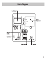
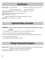
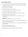
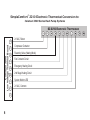
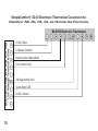
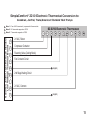
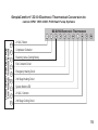
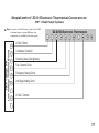
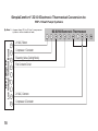
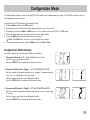
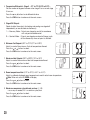
SC 2210
3-Stage Heat Pump
Manual Changeover
Battery or Hardwired
Non-Programmable Electronic Thermostat
•Configurable
•Three Stage Heat Pump Systems
•Backlit Display
•Field Calibration Feature
•Filter Check
•Relay Outputs (minimum voltage drop in thermostat)
•Ideally Suited for:
– Residential (New Construction/Replacement) – Light Commercial
Installation, Operation & Application Guide
For more information on our complete range of American-made
products – plus wiring diagrams, troubleshooting tips and more,
visit us at www.icmcontrols.com
Table of Contents
Parts Diagram........................................................................................................................................................
Specifications.........................................................................................................................................................
Important Safety Information................................................................................................................................
Package Contents/Tools Required..........................................................................................................................
To Remove Existing Thermostat...........................................................................................................................
To Install Thermostat.............................................................................................................................................
Wiring Diagram Conversions..................................................................................................................................
Carrier Split Stream Condensers and Heat Pump Systems................................................................................
Coleman 3000 Series Heat Pump Systems........................................................................................................
ComfortMaker CYC Series Heat Pump Systems................................................................................................
Heil-Quaker 867.814 Series and PH50 Series Heat Pump Systems...................................................................
Payne Reliant and Endura Model Heat Pump Systems......................................................................................
Rheem/Ruud: -PGB, -PFA, -PCB, -PLA, and -PKA Series Heat Pump Systems..................................................
Goodman, Janitrol, Trane/American Standard Heat Pumps...............................................................................
York -E1CS, -E1FB, -E1FH Heat Pump Systems................................................................................................
Lennox CB19 Heat Pump Systems....................................................................................................................
Lennox HP19 and HP20 Heat Pump Systems....................................................................................................
Lennox HP21 With CB21 PCB Heat Pump Systems...........................................................................................
Lennox HP22 With CB19 PCB Heat Pump Systems...........................................................................................
FHP 1 Heat Pump Systems................................................................................................................................
FHP 2 Heat Pump Systems................................................................................................................................
Configuration Mode................................................................................................................................................
Terminal Designator Descriptions..........................................................................................................................
SC2210 Output Chart............................................................................................................................................
Starting the Thermostat........................................................................................................................................
LED Indicators.......................................................................................................................................................
Testing the Thermostat.........................................................................................................................................
Mode of Operation.................................................................................................................................................
Troubleshooting.....................................................................................................................................................
1
2
2
2
3
3
5
5
6
7
8
9
10
11
12
13
14
15
16
17
18
19
21
21
21
22
22
24
25
Parts Diagram
Specifications
Electrical rating: •24 VAC (18-30 VAC)
• DC Power: 3.0 VDC (2 “AA” batteries included)
•1 amp maximum per terminal
• 4 amp maximum total load
Temperature control range: 45°F to 90°F (7°C to 32°C) Accuracy: ± 1°F (± 0.5°C)
System configurations: 3-stage heat, 2-stage cool heat pump
Timing:Anti-short Cycle: 5 minutes
Backlight Operation: Battery for 5 seconds, hardwired for 10 seconds
Terminations: C, L, R, B, O, W2, G, E, Y1, Y2, W3
Important Safety Information
WARNING!: Always turn off power at the main power supply before installing, cleaning, or removing
thermostat.
•This thermostat is for 24 VAC applications only; do not use on voltages over 30 VAC
•All wiring must conform to local and national electrical and building codes
•Do not use air conditioning when the outdoor temperature is below 50 degrees; this can damage your
A/C system and cause personal injuries
•Use this thermostat only as described in this manual
Package Contents/Tools Required
Package includes: SimpleComfort® 2210 thermostat on base, thermostat cover, wiring labels, screws and
wall anchors, Installation, Operation and Application Guide
Tools required for installation: Drill with 3/16” bit, hammer, screwdriver
To Remove Existing Thermostat
ELECTRICAL SHOCK HAZARD – Turn off power at the main service panel by removing the fuse
or switching the appropriate circuit breaker to the OFF position before removing the existing
thermostat.
1. Turn off power to the heating and cooling system by removing the fuse or switching the appropriate
circuit breaker off.
2. Remove cover of old thermostat. This should expose the wires.
3. Label the existing wires with the enclosed wire labels before removing wires.
4. After labeling wires, remove wires from wire terminals.
5. Remove existing thermostat base from wall.
6. Refer to the following section for instructions on how to install this thermostat.
To Install Thermostat
ELECTRICAL SHOCK HAZARD – Turn off power at the main service panel by removing the fuse
or switching the appropriate circuit breaker to the OFF position before removing the existing
thermostat.
IMPORTANT: Thermostat installation must conform to local and national building and electrical
codes and ordinances.
Note: Mount the thermostat about five feet above the floor. Do not mount the thermostat on an
outside wall, in direct sunlight, behind a door, or in an area affected by a vent or duct.
1. Turn off power to the heating and cooling system by removing the fuse or switching the appropriate
circuit breaker off.
To Install Thermostat (continued)
2.
To remove cover, insert and twist a coin or screwdriver in the slots on the sides of the thermostat.
3.
Put thermostat base against the wall where you plan to mount it (Be sure wires will feed through the
wire opening in the base of the thermostat).
4.
Mark the placement of the mounting holes.
5.
Set thermostat base and cover away from working area.
6.
Using a 3/16” drill bit, drill holes in the places you have marked for mounting.
7.
Use a hammer to tap supplied anchors in mounting holes.
8.
Align thermostat base with mounting holes and feed the control wires through wire opening.
9.
Use supplied screws to mount thermostat base to wall.
10. Insert stripped, labeled wires in matching wire terminals. See “Wiring Diagrams” section of this
manual (Pages 5-18).
CAUTION!: Be sure exposed portion of wires does not touch other wires.
11. Tighten screws on terminal block. Gently tug wire to be sure of proper connection. Double check that
each wire is connected to the proper terminal.
12. Seal hole for wires behind thermostat with non-flammable insulation or putty, or use an ICM insulated
wall plate (ACC-WP01).
13. Replace cover on thermostat by snapping it in place.
14. Turn on power to the system at the main service panel.
15. Test thermostat operation as described in “Testing the Thermostat” (Pages 22-24).
Wiring Diagram Conversions
SimpleComfort® 2210 Electronic Thermostat Conversion to:
Carrier Split Stream Condensers and Heat Pump Systems
SC 2210 Electronic Thermostat
Carrier Split Stream
Low Voltage Terminal Board
R
Y
O
G
E
W2
L
C
W3
24 VAC, Return
Compressor Contactor
Reversing Valve (Cooling Mode)
Fan Contactor Circuit
Emergency Heating Circuit
2nd Stage Heating Circuit
System Monitor LED
24 VAC, Common
3rd Stage Heating Circuit
SimpleComfort® 2210 Electronic Thermostat Conversion to:
Coleman 3000 Series Heat Pump Systems
SC 2210 Electronic Thermostat
Coleman 3000
Low Voltage Terminal Board
R
Y
B
G
E
W2
L
X
O
24 VAC, Return
Compressor Contactor
Reversing Valve (Heating Mode)
Fan Contactor Circuit
Emergency Heating Circuit
2nd Stage Heating Circuit
System Monitor LED
24 VAC, Common
SimpleComfort® 2210 Electronic Thermostat Conversion to:
ComfortMaker CYC Series Heat Pump Systems
Note 1: E and W2 terminals jumpered at thermostat.
Note 2: W2 terminal on Comfortmaker capped at PCB.
Note 3: X terminal on Comfortmaker capped at PCB.
Comfortmaker CYC
Low Voltage Terminal Board
R
Y
O
G
W1
W2
X
C
SC 2210 Electronic Thermostat
24 VAC, Return
Compressor Contactor
Reversing Valve (Cooling Mode)
Fan Contactor Circuit
2nd Stage Heating Circuit
Outdoor Thermostat (Capped)
Defrost Sensor (Capped)
(capped)
(capped)
24 VAC, Common
SimpleComfort® 2210 Electronic Thermostat Conversion to:
Heil-Quaker 867.814 Series and PH50 Series Heat Pump Systems
Note 1: E and W2 terminals jumpered at thermostat.
Heil-Quaker 867.814 and PH50
Low Voltage Terminal Board
R
Y
O
G
W1
W2
C
24 VAC, Return
Compressor Contactor
Reversing Valve (Cooling Mode)
Fan Contactor Circuit
2nd Stage Heating Circuit (Sequencer 1)
3rd Stage Heating Circuit (Sequencer 2)
24 VAC, Common
SC 2210 Electronic Thermostat
SimpleComfort® 2210 Electronic Thermostat Conversion to:
Payne Reliant and Endura Model Heat Pump Systems
SC 2210 Electronic Thermostat
Payne Reliant and Endura
Low Voltage Terminal Board
R
Y
O
G
E
W2
L
C
W3
24 VAC, Return
Compressor Contactor
Reversing Valve (Cooling Mode)
Fan Contactor Circuit
Emergency Heating Circuit
2nd Stage Heating Circuit
System Monitor LED
24 VAC, Common
3rd Stage Heating Circuit
SimpleComfort® 2210 Electronic Thermostat Conversion to:
Rheem/Ruud: -PGB, -PFA, -PCB, -PLA, and -PKA Series Heat Pump Systems
Rheem/Ruud PGB, PFA, PCB, PLA, PKA
Low Voltage Terminal Board
SC 2210 Electronic Thermostat
10
R
Y
B
G
W2
L
X
O
24 VAC, Return
Compressor Contactor
Reversing Valve (Heating Mode)
Fan Contactor Circuit
2nd Stage Heating Circuit
System Monitor LED
24 VAC, Common
SimpleComfort® 2210 Electronic Thermostat Conversion to:
Goodman, Janitrol, Trane/American Standard Heat Pumps
Goodman, Janitrol, Trane/American Standard
Low Voltage Terminal Board
Note 1: E and W2 terminals jumpered at thermostat.
Note 2: X2 terminal capped at PCB.
Note 3: T terminal capped at PCB.
R
Y
O
G
24 VAC, Return
Compressor Contactor
Reversing Valve (Cooling Mode)
Fan Contactor Circuit
(capped)
X2
W-U
B
T
SC 2210 Electronic Thermostat
2nd Stage Heating Circuit
24 VAC, Common
(capped)
11
SimpleComfort® 2210 Electronic Thermostat Conversion to:
York -E1CS, -E1FB, -E1FH Heat Pump Systems
Note 1: E and W2 terminals jumpered at thermostat.
York -E1CS, -E1FB, -E1FH
Low Voltage Terminal Board
R
12
Y
O
G
W
X
B
24 VAC, Return
Compressor Contactor
Reversing Valve (Cooling Mode)
Fan Contactor Circuit
2nd Stage Heating Circuit
System Monitor LED
24 VAC, Common
SC 2210 Electronic Thermostat
SimpleComfort® 2210 Electronic Thermostat Conversion to:
Lennox CB19 Heat Pump Systems
SC 2210 Electronic Thermostat
Lennox CB19
Low Voltage Terminal Board
R
Y
O
G
E
W1
L
C
T
24 VAC, Return
Compressor Contactor
Reversing Valve (Cooling Mode)
Fan Contactor Circuit
Emergency Heating Circuit
2nd Stage Heating Circuit
System Monitor LED
24 VAC, Common
(capped)
13
SimpleComfort® 2210 Electronic Thermostat Conversion to:
Lennox HP19 and HP20 Heat Pump Systems
SC 2210 Electronic Thermostat
Lennox HP19 and HP20
Low Voltage Terminal Board
V-VR
14
M
R
F
E
Y
X
24 VAC, Return
Compressor Contactor
Reversing Valve (Cooling Mode)
Fan Contactor Circuit
Emergency Heating Circuit
2nd Stage Heating Circuit
24 VAC, Common
SimpleComfort® 2210 Electronic Thermostat Conversion to:
Lennox HP21 With CB21 PCB Heat Pump Systems
SC 2210 Electronic Thermostat
Lennox HP21 with CB21 PCB
Low Voltage Terminal Board
R-VR
Y1
O
F
E
W1
L
X
Y2
24 VAC, Return
Compressor Contactor
Reversing Valve (Cooling Mode)
Fan Contactor Circuit
Emergency Heating Circuit
2nd Stage Heating Circuit
System Monitor LED
24 VAC, Common
2nd Stage Cooling Circuit
15
SimpleComfort® 2210 Electronic Thermostat Conversion to:
Lennox HP22 With CB19 PCB Heat Pump Systems
SC 2210 Electronic Thermostat
Lennox HP22 with CB19 PCB
Low Voltage Terminal Board
R-VR
M
R
F
E
Y
L
X
Y2
16
24 VAC, Return
Compressor Contactor
Reversing Valve (Cooling Mode)
Fan Contactor Circuit
Emergency Heating Circuit
2nd Stage Heating Circuit
System Monitor LED
24 VAC, Common
2nd Stage Cooling Circuit
SimpleComfort® 2210 Electronic Thermostat Conversion to:
FHP 1 Heat Pump Systems
Note: For units with ECM motors and the 641-065 interface board, connect W2 from the thermostat to the W1 at the heat pump.
FHP 1 Stage HP
Low Voltage Terminal Board
R
Y
O
G
E
W
C
SC 2210 Electronic Thermostat
24 VAC, Return
Compressor Contactor
Reversing Valve (Cooling Mode)
Fan Contactor Circuit
Emergency Heating Circuit
2nd Stage Heating Circuit
24 VAC, Common
17
SimpleComfort® 2210 Electronic Thermostat Conversion to:
FHP 2 Heat Pump Systems
Note 1: Jumper from W2 to Y2 for 2 compressor
systems without electric heat.
FHP 2 Stage HP
Low Voltage Terminal Board
R
Y
O
G
C
Y2
18
24 VAC, Return
Compressor 1 Contactor
Reversing Valve (Cooling Mode)
Fan Contactor Circuit
24 VAC, Common
Compressor 2 Contactor
SC 2210 Electronic Thermostat
Configuration Mode
The configuration mode is used to set the SC2210 to match your heating/cooling system. The SC2210 functions with up
to 3-stage heat pump systems.
To configure the SC2210, perform the following steps:
1. Slide the Mode switch to the OFF position.
2. Remove the cover of the thermostat by gently pulling on one of the corners.
3. Simultaneously hold the SW5 and SW6 buttons in for 5 seconds while the SC2210 is in OFF mode.
4. Press the
or
button to change settings within each screen.
5. Press the SW6 button to advance to the next screen.
Note: The SW5 button will return you to the previous screen.
6. To exit configuration mode, slide the Mode switch to Heat or Cool.
Configuration Mode Settings The setup screens for Configuration Mode are as follows:
1. Temperature Scale (F or C) – Choose Fahrenheit or Celsius.
Press the
or
button to select.
Press the SW6 button to advance to the next screen.
2. Temperature Differential – Stage 1 – (1°F to 3°F) (0.5°C to 1.5°C) – Set the number of degrees between your “setpoint” temperature and
your “turn on” temperature for first stage.
Press the
or
button to set differential value.
Press the SW6 button to advance to the next screen.
3. Temperature Differential – Stage 2 – (1°F to 6°F) (0.5°C to 3.0°C) – Set the number of degrees between when stage 1 turns on and stage
2 turns on.
Press the
or
button to set differential value.
Press the SW6 button to advance to the next screen.
SET
ROOM
REMOTE
DIFF
FILTER
SET
ROOM
REMOTE
DIFF
FILTER
SET
ROOM
DIFF
FILTER
SET
ROOM
REMOTE
DIFF
FILTER
REMOTE
SET
ROOM
REMOTE
DIFF
FILTER
19
4. Temperature Differential – Stage 3 – (1°F to 6°F) (0.5°C to 3.0°C) – Set the number of degrees between when stage 2 turns on and stage
3 turns on.
Press the
or
button to set differential value.
Press the SW6 button to advance to the next screen.
5. Staged Off Outputs Select whether the outputs for heating and cooling are staged off
independently or are satisfied simultaneously.
1 = Economy Mode – Outputs are staged on and off in accordance
with set point and differential. 0 = Comfort Mode – Outputs are staged on and and all stages cycle
off simultaneously when set point is satisfied.
SET
ROOM
SET
ROOM
SET
ROOM
REMOTE
DIFF
FILTER
REMOTE
DIFF
FILTER
6.
Minimum Cool Setpoint (45°F to 75°F) (7°C to 24.0°C)
Adjust to control the minimum Cool set temperature allowed.
Press the
or
button to select.
Press the SW6 button to advance to the next screen.
SET
ROOM
7.
Maximum Heat Setpoint (55°F to 90°F) (13°C to 32°C)
Adjust to control the maximum Heat set temperature allowed.
Press the
or
button to select.
Press the SW6 button to advance to the next screen.
SET
ROOM
8.
Room temperature offset (+9°F to -9°F) (+4.5°C to -4.5°C)
Adjust to calibrate displayed room temperature to match actual room temperature.
Note: When not set to 0, ROOM will display
Press the
or
button to select.
Press the SW6 button to advance to the next screen.
9.
Maximum compressor cycles allowed per hour (-, 2-6)
- = as many as needed, 2-6 = maximum cycles/hour
Press the
or
button to select.
Press the SW6 button to advance to the next screen.
20
REMOTE
DIFF
FILTER
REMOTE
DIFF
FILTER
DIFF
FILTER
SET
ROOM
REMOTE
DIFF
FILTER
REMOTE
SET
ROOM
REMOTE
DIFF
FILTER
SET
ROOM
REMOTE
DIFF
FILTER
SET
ROOM
DIFF
FILTER
REMOTE
10. Filter Check time (300-800, – – –)
Set Fan Run Time (in hours) when Check Filter is displayed or set to – – – to disable.
Press the
or
button to select.
Note: After exiting configuration mode, to reset filter counter to zero and clear filter
warning, press the
and
button simultaneously for 5 seconds.
Press the SW6 button to review settings.
Slide the Mode switch to Heat or Cool to exit configuration.
SET
ROOM
REMOTE
DIFF
FILTER
(800 Hours)
Terminal Designator Descriptions
R – 24 VAC hot
C – 24 VAC common
O – cool active reversing valve
B – heat active reversing valve
Y1 – 1st stage cool, 1st stage heat
W2 – 2nd stage heat
Y2 – 2nd stage cool for 2 compressor systems
G – Fan
W3 – 3rd stage heat
L – Check indicator
E – 1st stage emergency
SC2210 Output Chart
Heat Pump
Emergency Heat HP
1ST Cool
2ND Cool
1ST Heat
2ND Heat
3RD Heat
Y1, G, O
Y1, Y2, G, O
Y1, G, B
Y1, W2, G, B
Y1, W2, W3, G, B
N/A
N/A
E, G
E, W2, G
E, W2, W3, G
Starting the Thermostat
CAUTION!: Do not use air conditioning when the outdoor temperature is below 50 degrees. This
can damage your air conditioning system and cause personal injuries.
1. Move the Fan Auto/On switch to the Auto position.
2. Move the Cool/Off/Heat/Emer switch to Cool or Heat, depending on the season.
SET
ROOM
DIFF
FILTER
REMOTE
21
LED Indicators
There are three LED indicators located on the front of the thermostat. They are designed to inform you
about the following:
LED
Color
AUX
Green
Function
CHECK
Red
•When this turns on, a malfunction has occurred somewhere in the heat
pump system
•Please contact a qualified service technician as soon as possible to check
your system
EMER
Red
•This light turns on whenever the emergency heat is manually selected
(Mode switch is in the EMER position)
•While in the emergency Heat mode, the heat pump compressor is off, and
the emergency heat (same as the auxiliary heat) maintains the setpoint
temperature
•This turns on when the auxiliary (second stage) heating is in operation
•It turns on 1-6°F below first stage and is user adjustable (see
Configuration, Step 3, Page 19)
Testing the Thermostat
Once the thermostat is installed, it should be thoroughly tested. CAUTION!: Do not energize the air conditioning system when the outdoor temperature is below 50
degrees. It can result in equipment damage or personal injury.
22
Cool Test
1. Slide Mode switch to Cool mode. 2. Adjust set temperature so it is 5 degrees below room temperature.
3. Air conditioning should come on within a few seconds.
4. Adjust the set temperature 2 degrees above the room temperature and the
A/C should turn off. There may be a fan delay on your system.
Note: There is a five minute time delay to protect the compressor after
it turns off. To temporarily bypass the five minute delay, slide the
Mode switch to OFF for 2 seconds and then back to Cool.
Cool Off Heat Emer
Heat Test
1. Slide Mode switch to Heat mode.
2. Adjust the set temperature so it is 5 degrees above the room temperature.
3. Heat should come on within a few seconds. Cool Off Heat Emer
4. Adjust the set temperature so it is 2 degrees below the room temperature and the heat should turn off. There may be a fan delay on
your system.
Note: There is a five minute time delay to protect the compressor after it turns off. To temporarily
bypass the five minute delay, slide the Mode switch to OFF for 2 seconds and then back to
Heat.
Emergency Heat Test
1. Slide Mode switch to Emer position (Emer LED lights).
2. Adjust the set temperature so it is 5 degrees above the room temperature. There may be a five minute delay.
3. Second stage heat should come on (Aux LED lights). 4. Adjust the set temperature so it is 2 degrees below the room temperature. Heat should turn off. There may be a fan delay on your system.
(Testing the thermostat continued on Page 24)
Cool Off Heat Emer
23
(Testing the thermostat continued from Page 23)
Fan Test
1. Slide Fan switch to On position.
2. Indoor fan turns on.
3. Slide Fan switch to Auto position. 4. Indoor fan turns off.
Auto
On
Auto
On
Mode of Operation
The SC2210 is a multi-stage, heat pump thermostat.
The SC2210 can use 24 VAC or batteries as a power supply. The SC2210 can be hardwired and have no
batteries installed in the battery compartment. It can also run on battery power only. When batteries are
installed and the thermostat is hardwired, the batteries will run the thermostat during a power outage.
When operating on battery power, the backlight will be on for 5 second intervals. When hardwired, the
backlight will be on for 10 second intervals.
The thermostat activates the heat pump when the room temperature is below the heat set temperature
(by the differential temperature). Auxiliary heat will be activated if the room temperature continues to
drop. Third stage heat is activated (on some systems) if the temperature drops further. The heat outputs
are staged off (configurable, setting 5, Page 20) as the room temperature increases. The thermostat will
not let the compressor come on for five minutes after it turns off. This protects your compressor.
When the room temperature is greater than the cool set temperature (by the differential temperature),
the cooling device is activated. Second-stage cooling will be activated if the room temperature continues
to rise. The cool outputs are staged off (configurable, setting 5, Page 20) as the room temperature
decreases. The thermostat will not let the compressor come on for five minutes after it turns off. This
protects your compressor.
The SC2210 has the following operating modes: OFF, Heat, Emergency Heat and Cool. In OFF mode, the
thermostat will not turn on heating or cooling devices. In the Heat mode, the thermostat controls the
heat pump system. In the Emergency Heat mode, the heat pump is bypassed and auxiliary becomes the
primary heat source. In the Cool mode, the thermostat controls the cooling system. The indoor fan can be
turned on in all operating modes using the Fan switch.
The SC2210 has an air filter check option also. When the fan run time exceeds the time set in the configuration (step 10, page 21), the filter reminder will be displayed. To reset the filter counter to zero and
clear the filter reminder from the display, press the
and
buttons in simultaneously for 5 seconds.
24
Troubleshooting
Symptom
No display
System fan does not come on
properly
Thermostat turns on and off too
frequently
Fan runs continuously
Room temperature is not correct
ROOM displays
filter displays
Auxiliary heat not on soon
enough
Problem not listed above
Remedy
For Hardwired Installation
Check for 24 VAC at thermostat; display is blank when 24 VAC is not present
For Battery Installation
Display is blank when batteries are drained or installed incorrectly
Verify wiring is correct
Adjust temperature differential (see “Temperature Differential,” Stage 1, Step 2,
Page 19)
Check fan On/Auto switch, ON position runs indoor fan continuously
Verify wall hole is plugged with putty or insulation; calibrate thermostat (see
“Configuration,” Step 8, Page 20)
Room temperature offset is not zero (see “Configuration,” Step 8, Page 20)
Fan run time has exceeded filter check time set in configuration (see
“Configuration,” Step 10, Page 21)
To reset counter to zero and clear filter warning, press the
and
button
simultaneously for 5 seconds
Adjust differential for 2nd and 3rd stage heating if required (see Configuration,
Steps 3 and 4, Pages 19-20)
Press the Reset button once; display will be refreshed and anti-short cycle timing
will be reset to zero
25
ONE-YEAR LIMITED WARRANTY
The Seller warrants its products against defects in material or workmanship for a period of one
(1) year from the date of manufacture. The liability of the Seller is limited, at its option, to repair,
replace or issue a non-case credit for the purchase prices of the goods which are provided to
be defective. The warranty and remedies set forth herein do not apply to any goods or parts
thereof which have been subjected to misuse including any use or application in violation of the
Seller’s instructions, neglect, tampering, improper storage, incorrect installation or servicing
not performed by the Seller. In order to permit the Seller to properly administer the warranty,
the Buyer shall: 1) Notify the Seller promptly of any claim, submitting date code information or
any other pertinent data as requested by the Seller. 2) Permit the Seller to inspect and test the
product claimed to be defective. Items claimed to be defective and are determined by Seller
to be non-defective are subject to a $30.00 per hour inspection fee. This warranty constitutes
the Seller’s sole liability hereunder and is in lieu of any other warranty expressed, implied or
statutory. Unless otherwise stated in writing, Seller makes no warranty that the goods depicted
or described herein are fit for any particular purpose.
Patent No. 424,953
7313 William Barry Blvd., North Syracuse, NY 13212
(Toll Free) 800-365-5525 (Phone) 315-233-5266 (Fax) 315-233-5276
www.icmcontrols.com
LIA200-2