1
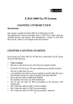
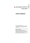
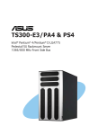
E-PoS 1000 Tec P4 System CHAPTER 1 INTRODUCTION Introduction This manual is for E-PoS 1000 Tec P4 System, a Mini Desk Top PC. The motherboard is all-in-one designed with 4 x AGP VGA,Audio sound and 10/100M Network chip build-in. This motherboard is designed with ATX structure. CHAPTER 2 GETTING STARTED On Receiving your E-PoS 1000 Tec P4 System, please check the following items: 1. What’s included Slim size or mini desk top case with ATX power supply installed. The Socket 478 P4 all-in-one ATX type motherboard pre-installed inside the slim size or Mini Desk Top case. 2 slots PCI Riser card pre-installed for E-POS 1000 TEC P4 One 40 pins flat cable for HDD and CD-ROM Pre-installed on the all-in-one ATX motherboard. One 34 pins flat cable for FDD pre-installed on the all-in-one ATX motherboard. One 10 pins flat cable for COM 1 port pre-installed. One 10 pins flat cable for COM 2 port pre-installed. One 10 pins flat cable for COM 3 port pre-installed. ( optional ) One 10 pins flat cable for COM 4 port pre-installed. ( optional ) 1 CPU and cooling fan with heat sink pre-install on the top of CPU. If you have ordered the system with CPU together. 2. 3. 4. 184 pins DDR DIMM memory module from 128MB up to 2GB, if you have ordered the system with main memory together. One set screw pack which including the following: a. M3 X0.5 screws 12 pcs for FDD/CD-ROM and card installation. b. M3 X1 screws 4 pcs for HDD installation. User’s manual 1 pcs. Power cord. CD-ROM disk software driver Checking the AC input voltage before turn on the power switch. The AC input voltage can be switch from 110 Volts to 230 Volts or from 230 Volts to 110 Volts. The AC input voltage convert switch is located on the back side of the power supply. Please double check whether the AC input voltage is matching at your country or not. If it is the wrong voltage, please make the correct setting of this switch. Installing the CPU, if you order the system without CPU installed. The CPU type is socket 478 and it can be either Intel Celeron speed up to 2.2Ghz or higher and Intel Pentium 4 speed up to 3.06 Ghz or higher available in the market. Please make sure the correct CPU pin 1 direction before insert the CPU into the CPU socket. Please also install the CPU cooling fan on the top of the CPU. Please check the CPU bus speed jumper setting at JP8 , the manufacturer default setting for JP8 is " Auto " which means CPU will auto detect the bus speed internally by itself. Installing the memory DDR DIMM module, if you order the system without memory DDR DIMM module installed. You can install the 184 pins DDR DIMM memory module into location DIMM1 and DIMM2 on your motherboard. Since 184 pins DDR DIMM module is 64 bits wide, therefore 1 piece of DDR DIMM module may match a 64 bits system , the available memory module from the market will be from 128 MB up to 1GB , so , the maximum memory size will be up to 2 GB for total 2 DDR DIMMs installed. 5. Installing the hard disk, if necessary. Please refer to the step 8 of the Mini Desk Top PC system installation at page No. 8 of this manual for detailed hard disk installation. 6. Installing the floppy disk, if necessary. 2 Please refer to the step 9 of the Mini Desk Top PC system installation at page No. 9 of this manual for detailed floppy disk installation. 7. Installing the CD-ROM drive, if necessary. Please refer to the step 10 of the Mini Desk Top PC system installation at page No. 9 of this manual for detailed CD-ROM drive installation. Please refer to page No. 12 of this manual for the slim CD-ROM installation for E-POS 1000 TEC P4/GE slim size PC. 8. Please refer to chapter 6 of this manual for the detailed BIOS CMOS SETUP. 9. Please Refer to chapter 7 for software driver installation for Intel chip set driver , 4 x AGP VGA driver , 10/100 Mbit Lan driver and audio driver and USB 2.0 driver. 10. Installing the I/O card, if necessary. The E-POS 1000 TEC P4 Slim Size PC has 2 PCI slots free , MFII-845GE slim size PC has 1 PCI + 1 AGP slots free, Please refer to step 19 of the Mini Desk Top PC system installation at page No. 10 of this manual for detailed I/O card installation. CHAPTER 3 SPECIFICATION 3.2 E-POS 1000 TEC P4/GE Slim Size PC specification Case size : 32 cm ( W ) x 33 cm ( L ) x 8 cm ( H ) Power supply : ATX 235 watts switching power supply 110/230 V switchable. Driver bay: 1 x 3.5” HDD + 1 x 3.5” FDD or HDD + 1 x slim CD-ROM Riser card : 2 x PCI ( standard ) or 1 x PCI + 1 x ISA mixed ( optional ) Or 1 x AGP + 1 x PCI (Only available for MFII-845GE version ) Front panel: Sound , 2 ports USB 2.0 , power LED , HDD LED , Lan LED , power switch , Reset switch. Back panel : Lan , VGA , 2 ports USB 2.0 , Printer , COM ,1,2,3,4 ( COM 3 3 & 4 optional ) PS/2 Keyboard , PS/2 mouse. Following are the free slot condition with all the drives installed: a. One 3.5" HDD + one 3.5" FDD or HDD + one slim CD-ROM installed + 4 COMs installed, then you still have one PCI slot free. b. One 3.5" HDD + one 3.5" FDD or HDD + one slim CD-ROM installed + 2 COMs installed , then you still have two PCI slots free. 3.3 Motherboard Engineering Specifications Product Name Form Factor CPU Type CPU Voltage System Speed CPU Operating Frequency Green /APM CPU Socket Chipset BIOS Cache VGA LVDS & TV-out (option) LAN Audio Memory type LPC I/O MF-845GV/GE Customer Design Socket 478 (Intel Pentium 4 ) 1.1V~1.85V (VRM 9.0) 1.30 ~3.06 GHz 400 MHz ( 100MHz x 4 ) /533MHz(133Hz x4) APM1.2 Socket 478 Intel 845GV/GE Chipset GMCH: 82845GV/GE 760 PIN FC-BGA ICH4: 82801DB 421 PIN BGA FWH Award BIOS Support ACPI Function 128K/256K/512K Level 2 (CPU integrated) 82845GV/GE built-in, AGP 4X,support CRT Chrontel CH7017 Realtek 8100B LAN controller(10/100Mb) ICH4 Built-in Sound controller + AC97 Codec STAC9750 (Line-out, Line-in, MIC.) 2 x DDR 2.5V PC 266/333 DDR SDRAM( without ECC Function) DIMM Module, Max. capacity - 2GB Winbond 83627HF: IrDAx1 Parallel x1, COM1(RS232),COM2(RS232/RS422/RS485), FDC 2.88MB/1.44MB,Hardware monitor(3 thermal inputs,6 voltage monitor inputs , VID0-4 , 1 chassis open detection ,3 Fan Header) Jumper selectable for +5V or + 12V at pin 9 of DB9 for COM 1 & 2 4 Secondary I/O (option) RTC/CMOS Battery PS2 Keyboard/Mouse Controller EPP/ECP Local bus IDE Board Size Power Connector Expansion slots USB (Universal Serial Bus) IrDA (Infrared Ray) Watchdog Timer System Voltages Other Features Winbond 83627HF: COM3,4 (RS232) 2 x10 pin header ( 2 sets ) Jumper selectable for +5V or + 12V at pin 9 of DB9 for COM 3 & 4 ICH4 Built-in Lithium Battery Winbond 83627HF Built-in Yes ICH4 built-in ,IDE1,IDE2 (Ultra DMA 33/66/100) Customer size ATX P4 type EISA slot for PCI & AGP 4 ports ,USB Vevision 2.0, 2 ports in the back and 2 ports in the front for MFII ; 4 ports in the back ( 2 ports optional in the bracket for MFIII ) pin header ,This allows infrared wireless communication. Yes ( 256 segments : 0,1,2,...255 sec/min) +5V,+12V,-12V,5VSB,+3.3V Modem Wakeup, LAN Wakeup , CHAPTER 4 INSTALLATION 4.2 E-POS 1000 TEC P4/GE Slim Size PC System installation The E-POS 1000 TEC P4/GE Slim Size PC system installation procedure will be similar to the MFIII-845GV/GE Mini Desk Top PC. Except the following devices need to do the special care. 1. Slim CD-ROM installation The slim CD-ROM needs to install a small PC board which converts the IDE interface of the slim CD-ROM to the standard IDE interface of the motherboard. Following is the block diagram of this converter board. 5 J2 CON2 J1 JP1 z J2 : This connector is to connect the audio signal to the sound card. z J1 : This connector is to connect the power supply for the slim CDROM. z CON2 : This connector is to connect the IDE interface to the motherboard. z JP1 : This jumper is for master/slave select of the slim CD-ROM. For different brand of the slim CD-ROM, The master /slave selection method is different, so you have to check with the supplier how to set the slim CD-ROM to the slave device. Because if you installed the hard disk with the slim CD-ROM together with the same IDE cable that you have to set the slim CD-ROM to the slave condition. Choose your slim CD-ROM vender and set the slim CD-ROM to the slave condition. Connects all the cables to J1, J2 and CON2 connectors. Step1. Installing the slim CD-ROM mounting bracket by screw in the 2 screws, on the HDD/FDD/CD-ROM holding bracket. Step2. Screw in the 2 M2 screws between the slim CD-ROM mounting bracket and the converter board. 6 CHAPTER 5 Motherboard diagram and jumper setting 5.1 MF-845GV/GE Motherboard Diagram & jumper location 7 5.2 MFIII-845GV/GE ALL-IN-ONE M/B jumper setting 1. JP1 = I R Connector 2. JP3 = CMOS Jumper select 1-2 = Normal ( Default ) 2-3 = Clear CMOS 3. JP6 = USB 3&4 Power source select 1-2 +5V 2-3 +5V standby 4. JP8 = CPU bus speed select 1-2 CPU auto select 2-3 100 Mhz Empty 133 Mhz 5. JP9 = USB 1&2 Power source select 1-2 +5V 2-3 +5V standby 6. JP10 = KB 1-2 +5V 2-3 +5V standby 7. JP11 = CRT or TV-out select 1-2: ON TV-out 1-2: OFF AGP CRT-out 8. JP13 = On board LAN Enable/Disable select 1-2: ON Enabled 1-2: OFF Disabled 9. JP16 =On board sound Enable/Disable select 1-2 Enabled 2-3 Disabled 10. JP17 = LVDS TFT LCD panel Power source select 8 1-2 2-3 +3.3V +5V 11. 12. 13. 14. 15. 16. J1 = Chassis Fan connector J2 = Chassis Fan or power fan connector J4 = WOL connector J5 = COM 2 Connector J6 = CPU Fan connector J7 = Power pin select for COM1 at pin 9 of DB9 1-2 Normal 3-4 +5V 5-6 +12V 17. J8 = Power pin select for COM2 at pin 9 of DB9 1-2 Normal 3-4 +5V 5-6 +12V 18. 19. 20. J9 = COM 1 Connector J10 = COM 4 Connector J11 = Power pin select for COM3 at pin 9 of DB9 1-2 Normal 3-4 +5V 5-6 +12V 21. 22. J12 = COM 3 Connector J13 = Power pin select for COM4 at pin 9 of DB9 1-2 Normal 3-4 +5V 5-6 +12V 23. 24. 25. 26. 27. 28. 29. 30. J14 = USB 3 & 4 Connector J15 = CD-IN connector J16 = Line in out , Mic-in connector J19 = Y.R.B out put connector J20 = TV – out connector J21A = LVDS TFT LCD panel connector J21B = LVDS TFT LCD panel connector J22 = Enable LCD panel back light 9 31. 32. 33. 34. 35. 36. 37. 38. 39. 40. 41. 42. 43. 44. Power1=ATX Power connector CN6 = ATX power connector for +12V IDE1 = Primary IDE Connector IDE2 = Secondary IDE Connector FDD = Floppy Disk Connector BAT1 = CMOS Battery socket VGA = VGA monitor connector LPT1 = Printer connector USB1 = 2 x USB 2.0 connector PWR_SW = Power switch connector for front bezel PWRLED = Power LED connector for front bezel RST_SW = Reset switch connector for front bezel LANLED = Lan LED connector for front bezel IDELED = HDD LED connector for front bezel Chapter 6 AWARD BIOS SETUP 6.1 BIOS Introduction The Award BIOS (Basic Input/Output System) installed in your computer system’s ROM supports Intel Pentium 4 processors. The BIOS provides critical low-level support for a standard device such as disk drives, serial ports and parallel ports. It also adds virus and password protection as well as special support for detailed finetuning of the chipset controlling the entire system. 6.2 BIOS Setup The Award BIOS provides a Setup utility program for specifying the system configurations and settings. The BIOS ROM of the system stores the Setup utility. When you turn on the computer, the Award BIOS is immediately activated. Pressing the <Del> key immediately allows you to enter the Setup utility. If you are a little bit late pressing the <Del> key, POST (Power On Self Test) will continue with its test routines, thus preventing you from invoking the Setup. If you still wish to enter Setup, restart the system by pressing the ”Reset” button or simultaneously pressing the <Ctrl>, <Alt> and <Delete> keys. You can also restart by turning the system Off and back On again. The following message will appear on the screen: Press <DEL> to Enter Setup In general, you press the arrow keys to highlight items, <Enter> to select, the 10 <PgUp> and <PgDn> keys to change entries, <F1> for help and <Esc> to quit. When you enter the Setup utility, the Main Menu screen will appear on the screen. The Main Menu allows you to select from various setup functions and exit choices. Phoenix - AwardBIOS CMOS Setup Utility Standard CMOS Features Advanced BIOS Features Advanced Chipset Features Integrated Peripherals Power Management Setup PnP/PCI Configurations PC Health Status Frequency/Voltage Control Load Fail-Safe Defaults Load Optimized Defaults Set Supervisor Password Set User Password Save & Exit Setup Exit Without Saving ESC : Quit F10 : Save & Exit Setup : Select Item Time, Date, Hard Disk Type… The section below the setup items of the Main Menu displays the control keys for this menu. At the bottom of the Main Menu just below the control keys section, there is another section which displays information on the currently highlighted item in the list. Note: If the system cannot boot after making and saving system changes with Setup, the Award BIOS supports an override to the CMOS settings that resets your system to its default. 11 Warning: It is strongly recommended that you avoid making any changes to the chipset defaults. These defaults have been carefully chosen by both Award and your system manufacturer to provide the absolute maximum performance and reliability. Changing the defaults could cause the system to become unstable and crash in some cases. 6.3 Standard CMOS Setup “Standard CMOS Setup” choice allows you to record some basic hardware configurations in your computer system and set the system clock and error handling. If the board is already installed in a working system, you will not need to select this option. You will need to run the Standard CMOS option, however, if you change your system hardware configurations, the onboard battery fails, or the configuration stored in the CMOS memory was lost or damaged. Phoenix - AwardBIOS CMOS Setup Utility Standard CMOS Features Date (mm:dd:yy) Thu, Mar 6 2003 Time (hh:mm:ss) 00 : 00 : 00 Menu Level IDE Primary Master Press Enter 13020 MB Press [Enter] to enter IDE Primary Slave IDE Secondary Master Press Enter None Press Enter None next page for detail hard drive settings IDE Secondary Slave Press Enter None Drive A Drive B 1.44M, 3.5 in. None Video EGA/VGA Halt On All, But Keyboard Base Memory Extended Memory Total Memory 640K 515072K 516096K 12 Item Help At the bottom of the menu are the control keys for use on this menu. If you need any help in each item field, you can press the <F1> key. It will display the relevant information to help you. The memory display at the lower right-hand side of the menu is read-only. It will adjust automatically according to the memory changed. The following describes each item of this menu. Date The date format is: Day : Month : Date : Year : Sun to Sat 1 to 12 1 to 31 1994 to 2079 To set the date, highlight the “Date” field and use the PageUp/ PageDown or +/keys to set the current time. Time The time format is: Hour : Minute : Second : 00 to 23 00 to 59 00 to 59 To set the time, highlight the “Time” field and use the <PgUp>/ <PgDn> or +/keys to set the current time. IDE Primary HDDs / IDE Secondary HDDs The onboard PCI IDE connectors provide Primary and Secondary channels for connecting up to four IDE hard disks or other IDE devices. Each channel can support up to two hard disks; the first is the “Master” and the second is the “Slave” . Press <Enter> to configure the hard disk. The selections include Auto, Manual, and None. Select ‘Manual’ to define the drive information manually. You will be asked to enter the following items. CYLS : HEAD : PRECOMP : LANDZ : SECTOR : Number of cylinders Number of read/write heads Write precompensation Landing zone Number of sectors The Access Mode selections are as follows: 13 Auto Normal (HD < 528MB) Large (for MS-DOS only) LBA (HD > 528MB and supports Logical Block Addressing) Drive A / Drive B These fields identify the types of floppy disk drive A or drive B that has been installed in the computer. The available specifications are: 360KB 1.2MB 720KB 1.44MB 2.88MB 5.25 in. 5.25 in. 3.5 in. 3.5 in. 3.5 in. Halt On This field determines whether or not the system will halt if an error is detected during power up. No errors All errors All, But Keyboard All, But Diskette All, But Disk/Key The system boot will not be halted for any error that may be detected. Whenever the BIOS detects a non-fatal error, the system will stop and you will be prompted. The system boot will not be halted for a keyboard error; it will stop for all other errors The system boot will not be halted for a disk error; it will stop for all other errors. The system boot will not be halted for a keyboard or disk error; it will stop for all others. Select Display Device The options for this field are Auto, CRT, LCD, CRT+LCD, TV, and CRT+TV. 6.4 Advanced BIOS Features This section allows you to configure and improve your system and allows you to set up some system features according to your preference. Phoenix - AwardBIOS CMOS Setup Utility Advanced BIOS Features 14 Virus Warning CPU L1 & L2 Cache Quick Power On Self Test First Boot Device Second Boot Device Third Boot Device Boot Other Device Swap Floppy Drive Boot Up Floppy Seek Boot Up Numlock Status Gate A20 Option Typematic Rate Setting Typematic Rate (chars/Sec) Typematic Delay (Msec) Security Option APIC Mode MPS Version Control For OS OS Select For DRAM>64MB Report No FDD For WIN 95 Small Logo (EPA) Show Disabled Enabled Enabled Floppy HDD-0 LS120 Enabled Disabled Enabled On Fast Disabled 6 250 Setup Enabled 1.4 Non-OS2 No Enabled ITEM HELP Allows you choose the VIRUS warning feature for IDE Hard Disk boot sector protection. If this function is enabled and someone attempt to write data into this area, BIOS will show a warning message on screen and alarm beep Virus Warning During and after system boot up, any attempt to write to the boot sector or partition table of the hard disk drive halts the system and an error message appears. You should then run an anti-virus program to locate the virus. Keep in mind that this feature protects only the boot sector, not the entire hard drive . The default is Disabled. Enabled :Activates automatically when the system boots up causing a warning message to appear when anything attempts to access the boot sector. Disabled :No warning message appears when anything attempts to access the boot sector. Note : Many disk diagnostic programs that access the boot sector table can trigger the virus warning message. If you plan to run such a program , we recommend that you first disable the virus warning. CPU L1 & L2 Cache This controls the status of the processor s internal Level One and Level Two cache. The default is Enabled. Enabled : This activates the processor s internal cache thereby increasing performance. Disabled : This deactivates the processor s internal cache thereby lowering performance. 15 Quick Power On Self Test This category speeds up the Power On Self Test (POST). The default is Enabled. Enabled :This setting will shorten or skip of the items checked during POST. Disabled :Normal POST. First The BIOS attempts to load the operating system from the devices in the se-quence selected in these items. Options:Floppy,LS120,HDD-0,SCSI,CDROM,HDD-1,HDD-2,HDD-3, ZIP100,USB-FDD,USB-ZIP,USB-CDROM,USB-HDD,LAN,Disabled. Boot Other Device When enabled, the system searches all other possible locations for an operating system if it fails to find one in the devices specified under the first, second , and third boot devices. The default is Enabled. Options: Enabled , Disabled. Swap Floppy Drive This will swap your physical drive letters A&B if you are using two floppy disks. The default is Disabled. Enabled : Floppy A&B will be swapped under the O/S. Disabled: Floppy A&B will be not swapped. Boot Up Floppy Seek If this item is enabled, it checks the size of the floppy disk drives at start-up time. You don t need to enable this item unless you have a legacy diskette drive with 360K capacity. The default is Disabled. Options : Enabled , Disabled. Boot Up NumLock Status This controls the state of the NumLock key when the system boots. The default is On. On : The keypad acts as a 10-key pad. Off : The keypad acts like cursor keys. Gate A20 Option This refers to the way the system addresses memory above 1 MB (extended memory ). The default is Normal. Normal : The A20 signal is controlled by the keyboard controller or chipset hardware. 16 Fast : The A20 signal is controlled by Port 92 or chipset specific method. Typematic Rate Setting This determines the keystrokes repeat rate.The default is Disabled. Enabled : Allows typematic rate and typematic delay programming. Disabled : The typematic rate and typematic delay will be controlled by the keyboard controller in your system. Typematic Rate (Chars/Sec) This is the number of characters that will be repeated by keyboard press. The default is 6. Options : 6~30 characters per second. Typematic Delay (Msec) This setting controls the time between the first and the second character displayed by typematic auto-repeat. The default is 250. Options : 250/500/750/1000 msec. Security Option This category allows you to limit access to the System and Setup, or just to Setup. The default is Setup. System : The system will not boot and the access to Setup will be denied if the correct password is not entered at the prompt. Setup :The system will boot; but the access to Setup will be denied if the incorrect password is not entered at the prompt. APIC Mode This item allows you to enable APIC (Advanced Programmabed Interrupt Controller) functionality. APIC is an Intel chip that provides symmetric multiprocessing (SMP) for its Pentium systems. The default is Disabled. Options : Enabled , Disabled. MPS Version Control For OS Specifies the Multiprocessor Specification (MPS). Version 1.4 supports multiple PCI bus configurations by incorporating extended bus definition. Enable this for Windows NT or Linux. For older operating systems, select Version 1.1 The default is 1.4. Options : 1.1,1.4. 17 OS Select for DRAM > 64MB Some operating systems require special handing. Use this option only if your system has greater than 64 MB of memory. The default is Non-OS2. OS2 : Select this if you are running the OS/2 operating system with greater than 64 MB of RAM. Non-OS2 : Select this for all other operating systems and configurations. Report No FDD For WIN 95 If you are running a system with no floppy drive and using Windows 95 ,select Yes for this item to ensure compatibility with the Windows 95 logo certification. Otherwise, select NO. Yes : The system has no floppy drive and you are using Windows 95. No :The system has an operating system other than Windows 95. Small Logo (EPA) Show This field enables the showing of the EPA logo located at the upper right of the screen during boot up. 6.5 Advanced Chipset Features This Setup menu controls the configuration of the chipset. Phoenix - AwardBIOS CMOS Setup Utility Advanced Chipset Features DRAM Timing Selectable CAS Latency Time Active to Precharge Delay DRAM RAS# to CAS# Delay DRAM RAS# Precharge Turbo Mode Memory Frequency For System BIOS Cacheable Video BIOS Cacheable Memory Hole At 15M-16M Delayed Transaction Delay Prior to Thermal Delay Aperture Size (MB) ** On-Chip VGA Setting On-Chip VGA On-Chip Frame Buffer Size Boot Display TV Standard Video Connector By SPD 2 6 3 3 Disabled Auto Enabled Enabled Disabled Enabled 16 Min 64 ITEM HELP Menu Level ** Enabled 8MB CRT Off Automatic DRAM Timing Selectable 18 For setting DRAM Timing, By SPD is following Intel PC DDR SDRAM Serial Presence Detect Specification. Options : Manual, By SPD. CAS Latency Time Enables you to select the CAS latency time. The value is set at the factory depending on the DRAM installed. Do not change the values in this field unless you change specifications of the installed DRAM and DRAM clock from DRAM Timing Selectable. The default is by DRAM SPD. Options : 1.5,2, and 2.5. Active to Precharge Delay This item specifies the number of clock cycles needed after a bank active command before a precharge can occur (sets the minimum RAS pulse width.). The default is by DRAM SPD. Options : 5,6,7. DRAM RAS# to CAS# Delay This item sets the timing parameters for the system memory such as the CAS (Column Address Strobe) and RAS (Row Address Strobe). The default is by DRAM SPD. Options :2,3. DRAM RAS# Precharge This item refers to the number of cycles required to return data to its original location to close the bank or the number of cycles required to page memory before the next bank activate command can be issued. The default is by DRAM SPD. Options :2,3. Turbo Mode Enable you to set the system to enter “ Turbo “ mode. The default is “ Disabled “ . Memory Frequency For Enable you to set the memory frequency for the installed memory. Select “ Auto “ ( default ) to enable the system to set the memory frequency automatically according to the installed DRAM. 19 System BIOS Cacheable This item allows the system to be cached in memory for faster execution. The default is Enabled. Options : Disabled , Enabled. Video BIOS Cacheable This item allows the video to be cached in memory for faster execution. The default is Disabled. Options : Disabled , Enabled. Memory Hole At 15M-16M You can reserve this area of system memory for ISA adapter ROM. When this area is reserved, it cannot be cached. The user information of peripherals that need to use this area of system memory usually discusses their memory requirements. Options : Enabled, Disabled. Delayed Transaction The mainboard s chipset has an embedded 32-bit post write buffer to support delay transactions cycles. Select Enabled to support compliance with PCI specification version 2.1. The default is Enabled. Options : Enabled, Disabled. Delay Prior to Thermal Set this item to enable the CPU Thermal function to engage after the specified time. The default is 16 minutes. Options : 4,8,16,32 minutes. AGP Aperture Size (MB) This option determines the effective size of the AGP Graphic Aperture , where memory-mapped graphic data structures are located. The default setting is “ 64 “ . Options :4,8,16,32,64,128,256 MB On-Chip VGA This item allows you to control the on-chip VGA. Options : Enabled, Disabled. 20 On-Chip Frame Buffer Size This item allows you to control the on-chip frame buffer size. Options : 1MB,8MB. Boot Display This item allows you to selcet the boot display device. Options : CRT,TV,EFP. TV Standard This item allow you to select the display for TV –out if you have ordered the motherboard with TV-out feature on it. Video Connector This item allow you to detect the video connector which connected on the motherboard , the default setting is “ Auto “ which will detect the video connector automatically. 6.6 Integrated Peripherals Phoenix - AwardBIOS CMOS Setup Utility Integrated Peripherals On-Chip Primary PCI IDE IDE Primary Master PIO IDE Primary Slave PIO IDE Primary Master UDMA IDE Primary Slave UDMA On-Chip Secondary PCI IDE IDE Secondary Master PIO IDE Secondary Slave PIO IDE Secondary Master UDMA IDE Secondary Slave UDMA USB Controller USB 2.0 Controller USB Keyboard Support USB Mouse Support AC97 Audio AC97 Modem Init Display First IDE HDD Block Mode POWER ON Function KB Power ON Password Hot Key Power ON Onboard FDC Controller Onboard Serial Port 1 Onboard Serial Port 2 UART Mode Select RxD , TxD Active IR Transmission Delay Enabled Auto Auto Auto Auto Enabled Auto Auto Auto Auto Enabled Enabled Enabled Enabled Auto Disabled Onboard Enabled BUTTON ONLY Enter Ctrl-F1 Enabled 3F8/IRQ4 2F8/IRQ3 Normal Hi,Lo Enabled 21 ITEM HELP Menu Level UR2 Duplex Mode Use IR Pins Onboard Parallel Port Parallel Port Mode EPP Mode Select ECP Mode Use DMA PWRON After PWR-Fail Game Port Address Midi Port Address Midi Port IRQ Onboard Serial Port 3 Serial Port 3 Use IRQ Onboard Serial Port 4 Serial Port 4 Use IRQ Half IR-Rx2Tx2 378/IRQ7 SPP EPP1.7 3 Off 201 330 10 3E8 IRQ10 2E8 IRQ11 On-Chip Primary/Secondary PCI IDE The integrated peripheral controller contains an IDE interface with support for two IDE channels. Select Enabled (default) to activate each channel separately. IDE Primary/Secondary Master/Slave PIO The four IDE PIO (Programmed Input/Output) fields let you set a PIO mode (0-4) for each of the four IDE devices that the onboard IDE interface supports. Modes 0 through 4 provide successively increased performance. In Auto mode, the system automatically determines the best mode for each device. The default is Auto. Options : Auto, Mode 0~4. IDE Primary/Secondary Master/Slave UDMA This allows you to select the mode of operation for the Ultra DMA-33/66/100 implementation is possible only if your IDE hard drive supports it and the operating environment includes a DMA driver (Windows 95 OSR2 or a third-party IDE bus master driver).If your hard drive and your system software both support Ultra DMA-33/66/100,select Auto to enable UDMA mode by BIOS or you can select mode by manual. Options : Auto , Disabled. USB Controller Enables the all USB controller. Options : Disabled , Enabled. USB 2.0 Controller Enables the EHCI (USB2.0) controller. Options : Disabled , Enabled. 22 USB keyboard Support Your system contains a Universal Serial Bus (USB) controller and you have a USB keyboard. The default is Auto detect. Options : Disabled , Enabled. USB Mouse Support Your system contains a Universal Serial Bus (USB) controller and you have a USB Mouse. The default is Disabled. Options : Disabled , Enabled. AC97 Audio This item allows you to decide to auto or disable the chipset family to support AC97 Audio. The function setting AC97 Audio Codec states. The system default is Auto. Options : Auto , Disabled. AC97 Modem This item allows you to decide to Modem or disable the chipset family to support AC97 Modem. The function setting AC97 Modem Codec states. The system default is Modem. Options : Auto , Disabled. Init Display First If two video cards are used (1 AGP and 1 PCI) this specifies which one will be the primary display adapter.The default is PCI Slot. Options : PCI Slot , AGP. IDE HDD Block Mode IDE Block Mode allows the controller to access blocks of sectors rather than a single sector at a time. The default is Enabled. Enabled: Enabled IDE HDD Block Mode. Provides higher HDD transfer rates. Disabled: Disabled IDE HDD Block Mode. POWER ON Function Enables computer power on by keyboard, mouse ,or hotkey activity. The default is Hot KEY. Password: Requires you to enter a password when using the keyboard to power on. Set the password in the next field 23 KB Power ON Password Press Hot key power ON Enables you to set a hot key combination to be used for powering on the system. The default is Ctrl-F1. Options: Ctrl-F1~Ctrl F12. Onboard FDD Controller Select Enabled if your system has a floppy disk controller(FDC) installed on the System board and you wish to use it. If you install an and-in FDC or the system has no floppy drive, select Disabled in this field. Options: Disabled , Enabled. Onboard Serial Port 1/2 Select an address and corresponding interrupt for the first and second serial ports. Options: 3F8/IRQ4,2E8/IRQ3,3E8/IRQ4,2F8/IRQ3,Disabled,Auto. UART Mode Select This filed allows the users to configure what IR mode the 2nd serial port should use.The default is Normal. Options:Normal,IrDA and ASKIR. RxD , TxD Active This field configures the receive and transmit signals generated from the IR port. The default is Hi Lo (when UART Mode Select is not set to Normal). Options:Hi Hi,Hi Lo, Lo Hi, and Lo Lo. IR Transmission Delay This item allows you to enabled/disabled IR transmission delay. Options:Enabled , Disabled. 24 UR2 Duplex Mode This item allows you to select IR half/full duplex function. Options: Half , Full. Use IR Pins This item allows you to select IR transmission routes, one is RxD2, TxD2(COM Port) and the other is IR-Rx2Tx2. Options:IR-Rx2Tx2,RxD2,TxD2. Onboard Parallel Port This field allows the user to configure the LPT port. Options: 378/IRQ7,278/IRQ5,3BC/IRQ7,Disabled. Parallel Port Mode This field allows the user to select the parallel port mode. Options:SPP,EPP,ECP,ECP+EPP. EPP Mode Select This item allows you to determine the IR transfer mode of onboard I/O chip. Options:EPP 1.9 , EPP 1.7. ECP Mode USE DMA This field allows the user to select DMA 1 or DMA 3 for the ECP mode. Options: DMA 1 , DMA 3. PWRON After PWR-Fail This item enables your computer to automatically restart or return to its last operating status after power returns from power failure. Off: The system stays off after a power failure. Former-Sts: The system returns to the state it was in just prior to the power failure. Game port Address Select an address for the Game port. Options: 201 (default) , 209 ,Disabled. Midi port Address Select an address for the Midi port. 25 Options: 209,300,330(default),Disabled. Midi Port IRQ Select an interrupt for the Midi port. Options: 5,10(default). Onboard Serial Port 3/4 Select an address and corresponding interrupt for the first and second serial ports. Options: 3F8,2E8,3E8,2F8,Disabled Serial Port 3/4 Use IRQ Select an interrupt for the Serial Port. Options: IRQ3,IRQ4,IRQ5,IRQ7,IRQ10,IRQ11. 6.7 Power Management Setup The Power Management Setup allows you to save energy of your system effectively. Phoenix - AwardBIOS CMOS Setup Utility Power Management Setup ACPI Function Enabled ACPI Suspend Type S1(POS) Auto User Define Run VGABIOS if S3 Resume Power Management Video Off Method Video Off In Suspend Suspend Type Modem Use IRQ Suspend Mode HDD Power Down Soft-Off by PWR-BTTN CPU THRM-Throttling Wake Up by PCI card Power On by Ring USB KB Wake-UP From S3 Resume by Alarm Date (of Month) Alarm Time (hh : mm : ss) Alarm ITEM HELP DPMS Yes Stop Grant 3 Disabled Disabled Instant-Off 50.0% Enabled Enabled Disabled Disabled 0 0:0:0 ** Reload Global Times Events ** Primary IDE 0 Primary IDE 1 Secondary IDE 0 Secondary IDE 1 FDD,COM,LPT Port PCI PIRQ[A-D]# Disabled Disabled Disabled Disabled Disabled Disabled 26 Menu Level ACPI Function Use this option to enable or disable the ACPI function ACPI Suspend Type This item allows you to select S1(POS) or S3(STR) function. When set to Options: S1(POS) , S3(STR) , S1&S3. Run VGABIOS if S3 Resume This determines whether or not to enable the system to run the VGA BIOS when resuming from S3(STR) or S1&S3. Options: Auto,Yes,No. Power Management Use this to select your Power Management selection. The default is User define. Max. saving:Maximum power savings. Inactivity period is 1 minute in each mode. Min. saving: Minimum power savings. Inactivity period is 1 hour in each mode. User define: Allows user to define PM Timers parameters to control power saving mode. Video Off Method This option allows you to select how the video will be disabled by the power management. The default is V/H Sync+Blank. V/H SYNC + Blank: System turns off vertical and horizontal synchronization port and writes blanks to the video buffer. DPMS Support: Select this option if your monitor supports the Display Power Management Signaling (DPMS) standard of the Video Electronics Standards Association (VESA). Use the soft-ware supplied for your video subsystem to select video power management values. Blank Screen: System only writes blanks to the video buffer. Video Off In Suspend Lets you enable the video to power off in suspend mode. No: Video power off not controlled by power management. YES:Video powers off after time shown in suspend mode setting. 27 Suspend Type Determines CPU status during power saving mode. Stop Grant: CPU goes into idle mode during power saving mode. PwrOn suspend: CPU and system remain powered on in suspend mode. MODEM Use IRQ Name the interrupt request (IRQ) line assigned to the modem (if any) on your system. Activity of the selected IRQ always awakens the system. Default is IRQ3. Options: N/A,3,4,5,7,9,10,11. Suspend Mode Enabled and after the set time of system inactivity , all devices except the CPU will be shut off. Options: Disabled,1,2,4,8,12,20,30,40 Min and 1 Hour. HDD Power Down When enabled and after the set time of system inactivity,the hard disk drive will be powered down while all other devices remain active. Options: Disabled, 1~15 Min. Soft-off by PWR-BTTN Use this to select your soft-off function. The default is Instant Off. Instant Off: Turns off the system instantly. Delay 4 Second:Turns off the system after a 4 second delay. If momentary press of button, the system will go into Suspend Mode. Press the power button again to make system back to work. CPU THRM-Throttling This item sets the percentage of time that the CPU is idled if CPU throttling is initiated by excess heat. The default setting is 50%. Options:12.5%,25.0%,37.5%,50.0%,62.5%,75.0%,87.5%. Wake-Up by PCI card An input signal from PME on the PCI card awakens the system from a soft off state. Options: Enabled , Disabled. Power On by Ring When enabled , any modem or LAN activity awakens the system from power savings mode. 28 Options: Enabled , Disabled. USB KB Wake-Up From S3 When enabled , any USB activity awakens the system from power savings mode. Options: Enabled , Disabled. Resume by Alarm When enabled , you can set the date and time in the following two fields. Any event occurring at the specified date or time awakens the system from power savings mode. ** Reload Global Timer Events** Primary/Secondary IDE 0/1 Any activity occurring on these channels awakens the system from power savings mode. FDD , COM ,LPT Port When enabled , any event occurring on these ports awakens the system from power savings mode. PCI PIRQ[A-D]# When enabled , any event occurring on these PCI slots awakens the system from power savings mode. 6.8 PNP/PCI Configurations This option configures the PCI bus system. All PCI bus systems on the system use INT#, thus all installed PCI cards must be set to this value. Phoenix - AwardBIOS CMOS Setup Utility PnP/PCI Configurations Reset Configuration Data Disabled ITEM HELP Resources Controlled By IRQ Resources Auto [ESCD] Press Enter PCI/VGA Palette Snoop Disabled 29 Reset Configuration Data This setting allows you to clear ESCD data. The default is Disabled. Disabled: Normal Setting. Enabled: If you have plugged in some Legacy cards to the system and they were recorded into ESCD (Extended System Configuration Data), you can set this field to Enabled in order to clear ESCD. Resources Controlled by Determines what controls system PNP/PCI resources. The default is Auto (ESCD). Manual: PNP Card s resources are controlled manually. The IRQ Resources field becomes available and you can set which IRQ-X and DMA-X are assigned to PCI/ISA PNP or Legacy ISA Cards. Auto: If your ISA card and PCI cards are all PNP cards , BIOS assigns the interrupt resource automatically. PCI/VGA Palette Snoop This item is designed to overcome problems that can be caused by some nonstandard VGA cards. This board includes a built-in VGA system that does not require palette snooping so you must leave this item disabled. Options: Enabled , Disabled. 6.9 PC Health Status This section shows the parameters in determining the PC Health Status. These parameters include temperatures, fan speeds and voltages. Phoenix - AwardBIOS CMOS Setup Utility PC Health Status CPU Warning Temperature Current System Temp. Current CPU1Temperature Current CPUFAN1 Speed Current CPUFAN2 Speed Current CPUFAN3 Speed Vagp (V) Vcore(V) Vdimm(V) + 5 V + 12 V - 12 V - 5 V Disabled ITEM HELP 39C/102 F 24 C/75 F 2721 RP M 0 RPM 0 RPM 1.53V 1.47V 2.54V 5.10V 11.85V -11.45V -4.89V 30 VBAT(V) 5VSB (V) Shutdown Temperature 3.18V 4.92V Disabled CPU Warning Temperature Sets the temperature at which the computer will respond to an overheating CPU. The default is Disabled. Options: Disabled,50ÛC/122ÛF~70ÛC/158ÛF. Current System Temp. Displays the current system temperature. Current CPU1 Temperature Displays the current CPU1 temperature. Current CPUFAN1/2/3 Speed Displays the current speed of the CPU, chassis , and power fan speed in RPMs. Vagp (V) The voltage level of power supplied to AGP card. Vcore (V) The voltage level of the CPU(Vcore). Vdimm (V) The voltage level of the DRAM. ± ± Shutdown Temperature 31 6.10 Frequency/Voltage Control This section shows the user how to configure the processor frequency. Phoenix - AwardBIOS CMOS Setup Utility Frequency/Voltage Control Auto Detect PCI Clk Enabled Spread Spectrum Disabled ITEM HELP Auto Detect PCI Clk When enabled the mainboard automatically disables the clock source for a PCI slot which does not have a module in it, reducing EMI (ElectroMagnetic Interference). The default is Enabled. Spread Spectrum If you enabled spread spectrum, it can significantly reduce the EMI (ElectroMagnetic Interference) generated by the system. 6.11 Load Fail-Safe Defaults When you press <Enter> on this item you get a confirmation dialog box: Load Fail-Safe Defaults (Y/N)? N Pressing 6.12 Load Optimized Defaults When you press <Enter> on this item you get a confirmation dialog box: Load Optimized Defaults (Y/N)? N Pressing 6.13 Set Supervisor/User Password These items are used to install a password. A Supervisor password takes precedence over a User password , and the Supervisor limits the activities of a User. You can set either a supervisor or user password , or both of them: Supervisor password: authorized to enter and change the options of the setup menus. 32 User password: authorized to enter, but not authorized to change the options of the setup menus. When you select Set User/Supervisor Password, the following message appears prompting you to type a password: ENTER PASSWORD: Type the password , up to eight characters in length , and press <Enter>. The password typed now clears any previously entered password from CMOS memory. You will be prompted to confirm the password. Type the password and press <Enter>. You may also press <ESC> to abort the selection and not enter a password. To disabled a password , press <Enter> when you are prompted to enter the password. A message will confirm the password is disabled: PASSWORD DISABLED. Once the password is disabled , the system will boot and you can enter Setup freely. When a password has been enabled, you will be prompted to enter it every time you try to enter Setup. This prevents an unauthorized person from changing any part of your system configuration. Additionally, when a password is enabled , you can also require the BIOS to request a password every time your system is rebooted. This prevents unauthorized use of your computer. You determine when the password is required within the BIOS Features Setup menu 6.14 Save & Exit Setup This option allows you to determine whether or not to accept the modifications. If you type “ Y” , you will quit the setup utility and save all changes into the CMOS memory. If you type “ N” , you will return to Setup utility. 6.15 Exit Without Saving Pressing <Enter> on this item asks for confirmation: Save to CMOS and EXIT (Y/N) ? Y Pressing 33 Exit without saving Pressing <Enter> on this item asks for confirmation: Quit without saving (Y/N)? Y This allows you to exit Setup without storing in CMOS any change. The previous selections remain in effect. This exits the Setup utility and restarts your computer. 6.16 POST Messages During the Power On Self-Test (POST), if the BIOS detects an error requiring you to do something to fix, it will either sound a beep code or display a message. If a message is displayed, it will be accompanied by: PRESS F1 TO CONTINUE, CTRL-ALT-ESC OR DEL TO ENTER SETUP POST Beep Currently there are two kinds of beep codes in BIOS. This code indicates that a video error has occurred and the BIOS cannot initialize the video screen to display any additional information. This beep code consists of a single long beep followed by two short beeps. The other code indicates that your DRAM error has occurred. This beep code consists of a single long beep repeatedly. Error Messages One or more of the following messages may be displayed if the BIOS detects an error during the POST. This list includes messages for both the ISA and the EISA BIOS. CMOS BATTERY HAS FAILED CMOS battery is no longer functional. It should be replaced. CMOS CHECKSUM ERROR Checksum of CMOS is incorrect. This can indicate that CMOS has become corrupt. This error may have been caused by a weak battery. Check the battery and replace if necessary. 34 DISK BOOT FAILURE, INSERT SYSTEM DISK AND PRESS ENTER No boot device was found. This could mean that either a boot drive was not detected or the drive does not contain proper system boot files. Insert a system disk into Drive A: and press <Enter>. If you assumed the system would boot from the hard drive, make sure the controller is inserted correctly and all cables are properly attached. Also be sure the disk is formatted as a boot device. Then reboot the system. DISKETTE DRIVES OR TYPES MISMATCH ERROR - RUN SETUP Type of diskette drive installed in the system is different from the CMOS definition. Run Setup to reconfigure the drive type correctly. DISPLAY SWITCH IS SET INCORRECTLY Display switch on the motherboard can be set to either monochrome or color. This indicates the switch is set to a different setting than indicated in Setup. Determine which setting is correct, and then either turn off the system and change the jumper, or enter Setup and change the VIDEO selection. DISPLAY TYPE HAS CHANGED SINCE LAST BOOT Since last powering off the system, the display adapter has been changed. You must configure the system for the new display type. EISA Configuration Checksum Error PLEASE RUN EISA CONFIGURATION UTILITY The EISA non-volatile RAM checksum is incorrect or cannot correctly read the EISA slot. This can indicate either the EISA non-volatile memory has become corrupt or the slot has been configured incorrectly. Also be sure the card is installed firmly in the slot. EISA Configuration Is Not Complete PLEASE RUN EISA CONFIGURATION UTILITY The slot configuration information stored in the EISA non-volatile memory is incomplete. 35 Note: When either of these errors appear, the system will boot in ISA mode, which allows you to run the EISA Configuration Utility. ERROR ENCOUNTERED INITIALIZING HARD DRIVE Hard drive cannot be initialized. Be sure the adapter is installed correctly and all cables are correctly and firmly attached. Also be sure the correct hard drive type is selected in Setup. ERROR INITIALIZING HARD DISK CONTROLLER Cannot initialize controller. Make sure the cord is correctly and firmly installed in the bus. Be sure the correct hard drive type is selected in Setup. Also check to see if any jumper needs to be set correctly on the hard drive. FLOPPY DISK CNTRLR ERROR OR NO CNTRLR PRESENT Cannot find or initialize the floppy drive controller. make sure the controller is installed correctly and firmly. If there are no floppy drives installed, be sure the Diskette Drive selection in Setup is set to NONE. Invalid EISA Configuration PLEASE RUN EISA CONFIGURATION UTILITY The non-volatile memory containing EISA configuration information was programmed incorrectly or has become corrupt. Re-run EISA configuration utility to correctly program the memory. NOTE: When this error appears, the system will boot in ISA mode, which allows you to run the EISA Configuration Utility. KEYBOARD ERROR OR NO KEYBOARD PRESENT Cannot initialize the keyboard. Make sure the keyboard is attached correctly and no keys are being pressed during the boot. 36 If you are purposely configuring the system without a keyboard, set the error halt condition in Setup to HALT ON ALL, BUT KEYBOARD. This will cause the BIOS to ignore the missing keyboard and continue the boot. Memory Address Error at ... Indicates a memory address error at a specific location. You can use this location along with the memory map for your system to find and replace the bad memory chips. Memory parity Error at ... Indicates a memory parity error at a specific location. You can use this location along with the memory map for your system to find and replace the bad memory chips. MEMORY SIZE HAS CHANGED SINCE LAST BOOT Memory has been added or removed since the last boot. In EISA mode use Configuration Utility to reconfigure the memory configuration. In ISA mode enter Setup and enter the new memory size in the memory fields. Memory Verify Error at ... Indicates an error verifying a value already written to memory. Use the location along with your system’s memory map to locate the bad chip. OFFENDING ADDRESS NOT FOUND This message is used in conjunction with the I/O CHANNEL CHECK and RAM PARITY ERROR messages when the segment that has caused the problem cannot be isolated. OFFENDING SEGMENT: This message is used in conjunction with the I/O CHANNEL CHECK and RAM PARITY ERROR messages when the segment that has caused the problem has been isolated. PRESS A KEY TO REBOOT This will be displayed at the bottom screen when an error occurs that requires you to reboot. Press any key and the system will reboot. 37 PRESS F1 TO DISABLE NMI, F2 TO REBOOT When BIOS detects a Non-maskable Interrupt condition during boot, this will allow you to disable the NMI and continue to boot, or you can reboot the system with the NMI enabled. RAM PARITY ERROR - CHECKING FOR SEGMENT ... Indicates a parity error in Random Access Memory. Should Be Empty But EISA Board Found PLEASE RUN EISA CONFIGURATION UTILITY A valid board ID was found in a slot that was configured as having no board ID. NOTE; When this error appears, the system will boot in ISA mode, which allows you to run the EISA Configuration Utility. Should Have EISA Board But Not Found PLEASE RUN EISA CONFIGURATION UTILITY The board installed is not responding to the ID request, or no board ID has been found in the indicated slot. NOTE: When this error appears, the system will boot in ISA mode, which allows you to run the EISA Configuration Utility. Slot Not Empty Indicates that a slot designated as empty by the EISA Configuration Utility actually contains a board. NOTE: When this error appears, the system will boot in ISA mode, which allows you to run the EISA Configuration Utility. 38 SYSTEM HALTED, (CTRL-ALT-DEL) TO REBOOT ... Indicates the present boot attempt has been aborted and the system must be rebooted. Press and hold down the CTRL and ALT keys and press DEL. Wrong Board In Slot PLEASE RUN EISA CONFIGURATION UTILITY The board ID does not match the ID stored in the EISA non-volatile memory. NOTE: When this error appears, the system will boot in ISA mode, which allows you to run the EISA Configuration Utility. FLOPPY DISK(S) fail (80) o Unable to reset floppy subsystem. FLOPPY DISK(S) fail (40) o Floppy Type mismatch. Hard Disk(s) fail (80) o HDD reset failed Hard Disk(s) fail (40) o HDD controller diagnostics failed. Hard Disk(s) fail (20) o HDD initialization error. Hard Disk(s) fail (10) o Unable to recalibrate fixed disk. Hard Disk(s) fail (08) o Sector Verify failed. Keyboard is locked out - Unlock the key. BIOS detect the keyboard is locked. P17 of keyboard controller is pulled low. Keyboard error or no keyboard present. Cannot initialize the keyboard. Make sure the keyboard is attached correctly and no keys are being pressed during the boot. Manufacturing POST loop. System will repeat POST procedure infinitely while the P15 of keyboard controller is pull low. This is also used for M/B burn in test. BIOS ROM checksum error - System halted. The checksum of ROM address F0000H-FFFFFH is bad. 39 Memory test fail. BIOS reports the memory test fail if the onboard memory is tested error. 6.17 POST Codes POST (hex) Description CFh Test CMOS R/W functionality. C0h Early chipset initialization: Disable shadow RAM -Disable L2 cache (socket 7 or below) -Program basic chipset registers C1h Detect memory -Auto-detection of DRAM size, type and ECC. -Auto-detection of L2 cache (socket 7 or below) C3h Expand compressed BIOS code to DRAM C5h Call chipset hook to copy BIOS back to E000 & F000 shadow RAM. 0h1 Expand the Xgroup codes locating in physical address 1000:0 02h Reserved 03h Initial Superio_Early_Init switch. 04h Reserved 05h 1. Blank out screen 2. Clear CMOS error flag 06h Reserved 07h 1. Clear 8042 interface 2. Initialize 8042 self-test 08h 1. Test special keyboard controller for Winbond 977 series Super I/O chips. 2. Enable keyboard interface. 09h Reserved 0Ah 1. Disable PS/2 mouse interface (optional). 2. Auto detect ports for keyboard & mouse followed by a port & interface swap (optional). 3. Reset keyboard for Winbond 977 series Super I/O chips. 0Bh Reserved 0Ch Reserved 40 POST (hex) 0Dh 0Eh 0Fh 10h 11h 12h 13h 14h 15h 16h 17h 18h 19h 1Ah 1Bh 1Ch 1Dh 1Eh 1Fh 20h 21h 22h Description Reserved Test F000h segment shadow to see whether it is R/W-able or not. If test fails, keep beeping the speaker. Reserved Auto detect flash type to load appropriate flash R/W codes into the run time area in F000 for ESCD & DMI support. Reserved Use walking 1’s algorithm to check out interface in CMOS circuitry. Also set real-time clock power status, and then check for override. Reserved Program chipset default values into chipset. Chipset default values are MODBINable by OEM customers. Reserved Initial Early_Init_Onboard_Generator switch. Reserved Detect CPU information including brand, SMI type (Cyrix or Intel) and CPU level (586 or 686). Reserved Reserved Initial interrupts vector table. If no special specified, all H/W interrupts are directed to SPURIOUS_INT_HDLR & S/W interrupts to SPURIOUS_soft _HDLR. Reserved Initial EARLY_PM_INIT switch. Reserved Load keyboard matrix (notebook platform) Reserved HPM initialization (notebook platform) Reserved 41 POST (hex) 23h 24h 25h 26h 27h 28h 29h 2Ah 2Bh 2Ch 2Dh 2Eh 2Fh 30h 31h Description 1. Check validity of RTC value: e.g. a value of 5Ah is an invalid value for RTC minute. 2. Load CMOS settings into BIOS stack. If CMOS checksum fails, use default value instead. 3. Prepare BIOS resource map for PCI & PnP use. If ESCD is valid, take into consideration of the ESCD’s legacy information. 4. Onboard clock generator initialization. Disable respective clock resource to empty PCI & DIMM slots. 5. Early PCI initialization: -Enumerate PCI bus number -Assign memory & I/O resource -Search for a valid VGA device & VGA BIOS, and put it into C000:0. Reserved Reserved Reserved Initialize INT 09 buffer Reserved 1. Program CPU internal MTRR (P6 & PII) for 0-640K memory address. 2. Initialize the APIC for Pentium class CPU. 3. Program early chipset according to CMOS setup. Example: onboard IDE controller. 4. Measure CPU speed. 5. Invoke video BIOS. Reserved Reserved Reserved 1. Initialize multi-language 2. Put information on screen display, including Award title, CPU type, CPU speed …. Reserved Reserved Reserved Reserved 42 POST (hex) 32h 33h 34h 35h 36h 37h 38h 39h 3Ah 3Bh 3Ch 3Dh 3Eh 3Fh 40h 41h 42h 43h 44h 45h 46h 47h 48h 49h 4Ah 4Bh 4Ch 4Dh Description Reserved Reset keyboard except Winbond 977 series Super I/O chips. Reserved Reserved Reserved Reserved Reserved Reserved Reserved Reserved Test 8254 Reserved Test 8259 interrupt mask bits for channel 1. Reserved Test 8259 interrupt mask bits for channel 2. Reserved Reserved Test 8259 functionality. Reserved Reserved Reserved Initialize EISA slot Reserved 1.Calculate total memory by testing the last double word of each 64K page 2.Program writes allocation for AMD K5 CPU. Reserved Reserved Reserved Reserved 43 POST (hex) 4Eh 4Fh 50h 51h 52h 53h 54h 55h 56h 57h 58h 59h 5Ah 5Bh 5Ch 5Dh 5Eh 5Fh 60h 61h 62h 63h 64h Description 1. Program MTRR of M1 CPU 2. Initialize L2 cache for P6 class CPU & program CPU with proper cacheable range. 3. Initialize the APIC for P6 class CPU. 4. On MP platform, adjust the cacheable range to smaller one in case the cacheable ranges between each CPU are not identical. Reserved Initialize USB Reserved Test all memory (clear all extended memory to 0) Reserved Reserved Display number of processors (multi-processor platform) Reserved 1. Display PnP logo 2. Early ISA PnP initialization -Assign CSN to every ISA PnP device. Reserved Initialize the combined Trend Anti-Virus code. Reserved (Optional Feature) Show message for entering AWDFLASH.EXE from FDD (optional) Reserved 1. Initialize Init_Onboard_Super_IO switch. 2. Initialize Init_Onbaord_AUDIO switch. Reserved Reserved Okay to enter Setup utility; i.e. not until this POST stage can users enter the CMOS setup utility. Reserved Reserved Reserved Reserved 44 POST (hex) 65h 66h 67h 68h 69h 6Ah 6Bh 6Ch 6Dh 6Eh 6Fh 70h 71h 72h 73h 74h 75h 76h 77h 78h 79h 7Ah 7Bh 7Ch 7Dh 7Eh Description Initialize PS/2 Mouse Reserved Prepare memory size information for function call: INT 15h ax=E820h Reserved Turn on L2 cache Reserved Program chipset registers according to items described in Setup & Auto-configuration table. Reserved 1. Assign resources to all ISA PnP devices. 2. Auto assign ports to onboard COM ports if the corresponding item in Setup is set to “ AUTO” . Reserved 1. Initialize floppy controller 2. Set up floppy related fields in 40:hardware. Reserved Reserved Reserved (Optional Feature) Enter AWDFLASH.EXE if : -AWDFLASH is found in floppy drive. -ALT+F2 is pressed Reserved Detect & install all IDE devices: HDD, LS120, ZIP, CDROM….. Reserved Detect serial ports & parallel ports. Reserved Reserved Detect & install co-processor Reserved Reserved Reserved Reserved 45 POST (hex) 7Fh 80h 81h 82h 83h 84h 85h 86h 87h 88h 89h 90h 91h 92h 93h 94h Description 1. Switch back to text mode if full screen logo is supported. -If errors occur, report errors & wait for keys -If no errors occur or F1 key is pressed to continue: Clear EPA or customization logo. Reserved Reserved 1. Call chipset power management hook. 2. Recover the text fond used by EPA logo (not for full screen logo) 3. If password is set, ask for password. Save all data in stack back to CMOS Initialize ISA PnP boot devices 1. USB final Initialization 2. NET PC: Build SYSID structure 3. Switch screen back to text mode 4. Set up ACPI table at top of memory. 5. Invoke ISA adapter ROMs 6. Assign IRQs to PCI devices 7. Initialize APM 8. Clear noise of IRQs. Reserved Reserved Reserved Reserved Reserved Reserved Reserved Read HDD boot sector information for Trend Anti-Virus code 1. Enable L2 cache 2. Program boot up speed 3. Chipset final initialization. 4. Power management final initialization 5. Clear screen & display summary table 6. Program K6 write allocation 7. Program P6 class write combining 46 POST (hex) 95h 96h FFh Description 1. Program daylight saving 2. Update keyboard LED & typematic rate 1. Build MP table 2. Build & update ESCD 3. Set CMOS century to 20h or 19h 4. Load CMOS time into DOS timer tick 5. Build MSIRQ routing table. Boot attempt (INT 19h) 47 Chapter 7 Driver Installation 7.1 Chipset Drivers Installation Follow the steps below to proceed with the Chipset drivers installation. 1. In your Windows operating system, click My ComputerÆ Compact DiscÆ MF-845GÆ ChipsetÆinfinst_autolÆ Setup 48 2. When the Welcome screen appears, click Next. 3. Click Next to agree with the license agreement statement and to continue. 49 4. Click Next to install the drivers listed. 5. Click Finish to restart the computer and for changes to take effect. 50 7.2 VGA Drivers Installation NOTE: Before installing the VGA drivers on Windows NT 4.0, you need to install Service Pack 3 or above. 1. In your Windows operating system, click My ComputerÆ Compact DiscÆ MF-845GÆ VGAÆ OSÆSetup 2. The welcome screen of the Twister Driver Setup will appear. Click Next to continue. 51 3. When the Start Copying Files screen appears, click Next to start copying the program files. 52 4. After file copying is done, the VGA driver installation is now completed. Click Finish to restart the computer and for changes to take effect. 53 7.3 LAN Drivers Installation Follow the steps below to proceed with the LAN drivers installation. 1. In your Windows operating system, click Start Æ Settings Æ Control Panel Æ System Properties. 54 2. Under System Properties, click on the Device Manager tab. Double click on Realtek 8139 PCI Fast Ethernet. Click the Driver tab as shown. Now click the Update Driver button. 3. When the Update Device Drivers Wizard appears, click Next to continue. 55 4. Click Next to “ Search for a better driver than the one your device is using now. (Recommended” . 5. Click “ Specify a location” and click Next to continue. 56 7.4 Audio Drivers Installation Follow the steps below to proceed with the SOUND drivers installation. 1. In your Windows operating system, click Start Æ Settings Æ Control Panel Æ System Properties. 57 2. Under System Properties, click on the Device Manager tab. Double click on Audio Device. Click the Driver tab as shown. Now click the Update Driver button. 3. When the Update Device Drivers Wizard appears, click Next to continue. 58 4. Click Next to “ Search for a better driver than the one your device is using now. (Recommended” . 5. Click “ Specify a location” and click Next to continue. 59 7.5 USB2.0 Drivers Installation Follow the steps below to proceed with USB2.0 drivers installation. 1. In your Windows operating system, click Start Æ Settings Æ Control Panel Æ System Properties. 60 2. Under System Properties, click on the Device Manager tab. Double click on Universal Serial Bus. Click the Driver tab as shown. Now click the Update Driver button. 3. When the Update Device Drivers Wizard appears, click Next to continue. 61 4. Click Next to “ Search for a better driver than the one your device is using now. (Recommended” . 5. Click “ Specify a location” and click Next to continue. 62