1
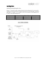
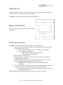
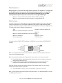
RGBW
RECESSED
LIGHTING
MANUAL
Coloronix, Inc.
5461 West Jefferson Boulevard
Los Angeles, California 90016
(323) 677-4242
http://www.rgbw.com
Page 1 - Coloronix RGBW Recessed Lighting Manual V2.0
Coloronix, Inc.
© 2011 Coloronix, Inc. All rights reserved.
According to copyright laws, this manual may not be copied—partially, or wholly—
without the written consent of Coloronix, Inc.
Despite full effort to avoid any clerical or printing inaccuracies, Coloronix, inc. accepts
no responsibility for any such inaccuracies to be found in this manual.
Coloronix, Inc.
5461 West Jefferson Boulevard
Los Angeles, California 90016
Tech Support: (909) RGBW-555
http://www.rgbw.com
Coloronix and the Coloronix logo are brands of Coloronix, Inc.
Any non-Coloronix brands or products found in this manual are not endorsed, branded,
or recommended for use by Coloronix, Inc.; rather, they are only references for
informational purposes. Coloronix has no responsibility for these products in regards
to either performance or use.
Page 2 - Coloronix RGBW Recessed Lighting Manual V2.0
Contents
Summary 4
Introduction 4
Scope 4
Who is this manual intended for? 4
Additional Supplies 4
Safety 5
Hazard Icon Key 5
Specifications 5
Planning for Installation 6
Unpacking 6
Preparation 6
Points to Consider About Data 6
Quick Step-by-Step Instructions 6
Setting Color Mode 7
Color Ray Stand Alone Mode 9
Installing Fixture 10-12
Installing Housing Rough-In Area 10
Installing Trim 11
Option of Wall Wash 11
Electrical Connection 11
Data Connection 12
Troubleshooting Guide 13-14
Further Troubleshooting 14
Replacing Failed Fixture 14
Warranty Information 15
Page 3 - Coloronix RGBW Recessed Lighting Manual V2.0
Summary
Introduction
RGBW Color Changing Downlights are active, top-of-the-line color changing fixtures.
They draw on solid-state elements in order to produce highlights and washes in
architectural spaces.
More specifically, “RGBW” is an acronym for “Red, Green, Blue, and White”. RGBW
LED color mixing luminaires have the potential to produce 4.3 billion colors, and 16.7
million white light tones.
When installed and operated according to this manual, these downlights will operate
safely and dependably for their rated lifespan.
These luminaries require a USITT DMX 512 control signal on four consecutive
channels total. The unit includes a DATA OUT output for connection to additional units
or other DMX512 devices. A Color Ray Signal from the internal stand-alone controller
or external controller can be used as well.
The downlights are UL 1598 damp location rated for use in indoor or outdoor
environments.
Scope
The purpose of this manual is to properly install and use color changing downlights at
peak performance.
This manual must be complimented by additional references, consultation from
qualified professional(s), and observance of state and local codes and regulations. This
rule applies to any interior structure, exterior structure, or environment.
Therefore, it is important to: “please read and comply with all instructions and
warnings in this manual when installing or using this product.”
Who Is This Manual Intended for?
This manual is intended for electrical contractors, electrical engineers, and licensed
electricians.
Additional Supplies
DMX control cable: Belden© 9841 or CAT5 RJ45 Cable
DMX512 compatible controller or Coloronix Color Ray Device (optional)
Page 4 - Coloronix RGBW Recessed Lighting Manual V2.0
Safety
Hazard Icon Key:
The “
DANGER” icon means avoiding pending danger will result in serious injury, or death.
The “
WARNING” icon means avoiding this warning may result may in serious injury, or death.
The “
CAUTION” icon means not exercising caution here may result in minor to moderate injury, or property damage.
The precautions are:
DANGER: Not turning off the main power before wiring, installing, connecting, or disconnecting this product may result in
serious injury, or death.
WARNING: Not following NEC codes, local codes, or consulting a certified professional may result in property damage,
serious injury, or death.
WARNING: Not following instructions, or safety labels may result in property damage, or serious injury.
WARNING: Modifying, servicing, or ignoring these safety indications may void the warranty.
WARNING: Inspect product before use. DO NOT use if damaged.
WARNING: Install safety cables per local and structural engineer’s code.
CAUTION: Hot swapping, not turning off fixtures before connection or disconnection, will void the warranty, and damage
property.
CAUTION: Do not go beyond the specified voltage, input current, maximum number of fixtures, or run length.
CAUTION: Do not use sharp tools near the reflector or lens.
CAUTION: Do not look directly into beam, with or without optical instruments.
Specifications
Power Input: Direct 120VAC 50Hz/60Hz or 24VDC Option Available 0.15A Max.
Power Consumption: 0.1-9W (40W for 4x9 and 6” round).
Environment: IC rated for direct contact with loose insulation in Damp and Wet Locations under a
covered ceiling.
L70 Life: 35,000 Hours.
Temperature Rating: 0°F - 120°F Ambient.
LED Die Colors: Red (620-635nm)
Green (520-535nm)
Blue (450-465nm)
Neutral White (4000k)
Safety: ETL Listed Complies to UL1598 and ANSI/UL 8750.
Page 5 - Coloronix RGBW Recessed Lighting Manual V2.0
Planning for Installation
Unpacking
The data enabler and trim are shipped assembled with no additional assembly needed.
Housing and trim are shipped in two different boxes.
Any optional accessories are included in the package. Use the packing list located on the
outside of the box to ensure all accessories are included.
Survey the unit to make sure the data enabler/trim are all intact—not cracked or
damaged. Any damages to the package or its contents are of the buyer’s responsibility;
please follow protocol for filing damage claims. Please recycle or appropriately discard of
any packing materials.
Preparation
Before Installation, Coloronix suggests:
•
•
•
•
Consulting the provided submittal drawings to recognize layouts of luminaries,
power supplies, and wiring layouts.
Drawing out a layout plan consisting of locations of luminaries and wiring.
Record DMX addresses on a mapping grid for easy reference and addressing
(where applicable).
An electrical inspector reviews all wiring plans.
Points to Consider About Data
•
•
Use a Belden© 9481 or similar cable for DMX data connectivity or Plenum rated
CAT5 8-wire cable.
AC Power and DATA cables may NOT run in the same conduit due to possible
induced errors.
Quick Step-by-Step Instructions
To successfully install RGBW Recessed Lighting, the steps are:
1.
2.
3.
4.
5.
6.
7.
Setting Color Mode or Setting Stand Alone Color Ray mode
Mounting and Alignment of data enabler
Installing Power Connections
Installing Data Connections
Installing Ceiling
Installing Trim
Ready to Go!
Page 6 - Coloronix RGBW Recessed Lighting Manual V2.0
Setting Color Mode (Optional)
Dip Switch Inside Housing
For installations requiring DMX control, set
the personalized DMX address using the
address table (Below) for address dip
switch position settings. The Dip Switch
Board can be found inside the housing
accessible below the ceiling. See figure.
Note: Up to 128 unique 4-channel
addresses can be set per DMX universe.
Dip Switch Setting
1
1,3
1,4
1,3,4
1,5
1,3,5
1,4,5
1,3,4,5
1,6
1,3,6
1,4,6
1,3,4,6
1,5,6
1,3,5,6
1,4,5,6
1,3,4,5,6
1,7
1,3,7
1,4,7
1,3,4,7
1,5,7
1,3,5,7
1,4,5,7
1,3,4,5,7
1,6,7
1,3,6,7
1,4,6,7
1,3,4,6,7
1,5,6,7
1,3,5,6,7
1,4,5,6,7
1,3,4,5,6,7
1,8
1,3,8
DMX
Channels
1-4
5-8
9-12
13-16
17-20
21-24
25-28
29-32
33-36
37-40
41-44
45-48
49-52
53-56
57-60
61-64
65-68
69-72
73-76
77-80
81-84
85-88
89-92
93-96
97-100
101-104
105-108
109-112
113-116
117-120
121-124
125-128
129-132
133-136
Dip Switch Setting
1,4,8
1,3,4,8
1,5,8
1,3,5,8
1,4,5,8
1,3,4,5,8
1,6,8
1,3,6,8
1,4,6,8
1,3,4,6,8
1,5,6,8
1,3,5,6,8
1,4,5,6,8
1,3,4,5,6,8
1,7,8
1,3,7,8
1,4,7,8
1,3,4,7,8
1,5,7,8
1,3,5,7,8
1,4,5,7,8
1,3,4,5,7,8
1,6,7,8
1,3,6,7,8
1,4,6,7,8
1,3,4,6,7,8
1,5,6,7,8
1,3,5,6,7,8
1,4,5,6,7,8
1,3,4,5,6,7,8
1,9
1,3,9
1,4,9
1,3,4,9
Page 7 - Coloronix RGBW Recessed Lighting Manual V2.0
DMX
Channels
137-140
141-144
145-148
149-152
153-156
157-160
161-164
165-168
169-172
173-176
177-180
181-184
185-188
189-192
193-196
197-200
201-204
205-208
209-212
213-216
217-220
221-224
225-228
229-232
233-236
237-240
241-244
245-248
249-252
253-256
257-260
261-264
265-268
269-272
Dip Switch Setting
1,5,9
1,3,5,9
1,4,5,9
1,3,4,5,9
1,6,9
1,3,6,9
1,4,6,9
1,3,4,6,9
1,5,6,9
1,3,5,6,9
1,4,5,6,9
1,3,4,5,6,9
1,7,9
1,3,7,9
1,4,7,9
1,3,4,7,9
1,5,7,9
1,3,5,7,9
1,4,5,7,9
1,3,4,5,7,9
1,6,7,9
1,3,6,7,9
1,4,6,7,9
1,3,4,6,7,9
1,5,6,7,9
1,3,5,6,7,9
1,4,5,6,7,9
1,3,4,5,6,7,9
1,8,9
DMX
Channels
273-276
277-280
281-284
285-288
289-292
293-296
297-300
301-304
305-308
309-312
313-316
317-320
321-324
325-328
329-332
333-336
337-340
341-344
345-348
349-352
353-356
357-360
361-364
365-368
369-372
373-376
377-380
381-384
385-388
Dip Switch Setting
DMX
Channels
1,3,8,9
1,4,8,9
1,3,4,8,9
1,5,8,9
1,3,5,8,9
1,4,5,8,9
1,3,4,5,8,9
1,6,8,9
1,3,6,8,9
1,4,6,8,9
1,3,4,6,8,9
1,5,6,8,9
1,3,5,6,8,9
1,4,5,6,8,9
1,3,4,5,6,8,9
1,7,8,9
1,3,7,8,9
1,4,7,8,9
1,3,4,7,8,9
1,5,7,8,9
1,3,5,7,8,9
1,4,5,7,8,9
1,3,4,5,7,8,9
1,6,7,8,9
1,3,6,7,8,9
1,4,6,7,8,9
1,3,4,6,7,8,9
1,5,6,7,8,9
1,3,5,6,7,8,9
1,4,5,6,7,8,9
389-392
393-396
397-400
401-404
405-408
409-412
413-416
417-420
421-424
425-428
429-432
433-436
437-440
441-444
445-448
449-452
453-456
457-460
461-464
465-468
469-472
473-476
477-480
481-484
485-488
489-492
493-496
497-500
501-504
505-508
Page 8 - Coloronix RGBW Recessed Lighting Manual V2.0
ColorRay Stand Alone Mode
For application not using DMX control, user can preprogram shows.
The fixture’s on board computer have been pre-configured with ColorRay programs. No additional
software or hardware is needed to access. Set the dip switch address for stand alone use (see table
below)
Dip Address
0
742
743
744
745
746
747
748
749
750
751
752
Setting
All Down
2,3,6,7,8,10
1,2,3,6,7,8,10
4,6,7,8,10
1,4,6,7,8,10
2,4,6,7,8,10
1,2,4,6,7,8,10
3,4,6,7,8,10
1,3,4,6,7,8,10
2,3,4,6,7,8,10
1,2,3,4,6,7,8,10
5,6,7,8,10
753
1,5,6,7,8,10
754
2,5,6,7,8,10
755
1,2,5,6,7,8,10
756
3,5,6,7,8,10
757
1,3,5,6,7,8,10
758
2,3,5,6,7,8,10
759
1,2,3,5,6,7,8,10
760
4,5,6,7,8,10
761
1,4,5,6,8,10
762
2,4,5,6,7,8,10
763
1,2,4,5,6,7,8,10
764
3,4,5,6,7,8,10
765
1,3,4,5,6,7,8,10
766
2,3,4,5,6,7,8,10
767
1,2,3,4,5,6,7,8,10
Function
Demo Mode: Red, Green, Blue, White
Static Color: Warm White
Static Color: Cool White
Static Color: Red
Static Color: Green
Static Color: Light Blue
Static Color: Dark Blue
Static Color: Orange
Static Color: Purple
Static Color: Pink
Static Color: Yellow
Full Rainbow:
Full Color Fade, Repeat
Full Rainbow:
Full Color Fade, Repeat
Full Rainbow:
Full Color Fade, Repeat
Full Rainbow:
Full Color Fade, Repeat
Christmas Colors:
Red, Green, Repeat
Christmas Colors:
Red, Green, Repeat
Christmas Colors:
Red, Green, Repeat
Christmas Colors:
Red, Green, Repeat
Cool Blue:
Dark Blue, Sky Blue, Repeat
Cool Blue:
Dark Blue, Sky Blue, Repeat
Cool Blue:
Dark Blue, Sky Blue, Repeat
Cool Blue:
Dark Blue, Sky Blue, Repeat
Exotic Colors:
Orange, Turquoise, Neon Green, Fuchsia, Repeat
Exotic Colors:
Orange, Turquoise, Neon Green, Fuchsia, Repeat
Exotic Colors:
Orange, Turquoise, Neon Green, Fuchsia, Repeat
Exotic Colors:
Orange, Turquoise, Neon Green, Fuchsia, Repeat
Speed
n/a
n/a
n/a
n/a
n/a
n/a
n/a
n/a
n/a
n/a
n/a
0.5 seconds
5 seconds
5 minutes
30 minutes
0.5 seconds
5 seconds
5 minutes
30 minutes
0.5 seconds
5 seconds
5 minutes
30 minutes
0.5 seconds
5 seconds
5 minutes
30 minutes
ColorRay Remote Control
For remote control of the ColorRay setting, use SCC5-In-Wall Receiver and remote control. All
programs and static colors can be set via remote control.
Note: Set dip switch 1-8 off and dip switch 9, 10 on for Color Ray stand alone mode
Page 9 - Coloronix RGBW Recessed Lighting Manual V2.0
Installing Fixture
Installing Housing Rough-In Area
Using a ½” electrical conduit, install the fixture into the ceiling cavity. You may use the
following as mounting rails (not included) to insert the rails through hanger brackets at
both sides: ¾” channel, 1-1/2” channel, 1/8”x1/2” bar stock, or T-bar fasteners. For
6” fixture, use supplied hanger bars.
Size of Cutout
(Inches)
3”
(diameter)
3-7/8”
Product Type
4”x9”
(square)
9-3/16” x 5”
Page 10 - Coloronix RGBW Recessed Lighting Manual V2.0
6”
(diameter)
6-1/2”
Installing Trim
Installing assembly: insert torsion springs into spring receivers (found in housing). For
3” round, insert trim held in place by spring blades.
WARNING: Power must be off before connecting LED trim.
Option of Wall Wash
For 4”x9” wall wash trim, install frame according
to diagram.
Electrical Connection
WARNING: Do not expose bare wires outside wire nut connectors.
1. Per local or “National Electric Code”, provide electrical service to junction
box located on the housing.
a. The insulation of supply wire must be rated for at least 90°C.
b. Junction boxes are rated for:
i. Max. 8 No. 12 AWG Circuit Conductors
ii. Also suitable for at least 90°C
2. Remove cover of junction box.
3. Remove proper round pryout, and then connect junction box with (not
included) proper connector.
4. Using properly sized wire nuts, connect lead wires of junction box (line,
neutral, and ground) to supply lead wires in the fixture.
a. WARNING: Do not leave bare conductors outside wire nut
connectors.
5. Connect green (from electrical service) to the supply side to the green wire
in the junction box. Connect black-to-black, and white-to-white.
a. Any excess wiring and connectors should be put in the junction box.
Then, replace the cover.
NOTE: Supply lead wires should not be connected to a dimmer of any sort.
Page 11 - Coloronix RGBW Recessed Lighting Manual V2.0
Data Connection
Note: Fixtures on a serial data link must be daisy chained in one single line. To comply with
the EIA-485 standard, no more than 32 fixtures should be connected on one data link.
Connecting more than 32 fixtures on one serial data link without the use of a DMX
optically-isolated splitter may result in deterioration of the digital DMX signal.
Maximum recommended serial data link distance: 500 m (1640 ft)
Maximum recommended number of fixtures on a serial data link: 32
DMX Data Cable
If installer prefers 3-wire data cables, we suggest a Belden© 9481 or equivalent cable which
meets the specifications for EIA RS-485 applications (Use PCL002 DMX hardwiring DMX
coupler). Standard microphone cables cannot transmit DMX data reliably over long distances.
The cable must have the following characteristics:
Type:
Maximum capacitance between conductors:
shielded, 2-conductor twisted pair
30 pF/ft
Maximum capacitance between conductor and shield:
55 pF/ft
Maximum resistance:
20 ohms/1000ft
Normal impendance:
100~140 ohms
If installer prefers a RJ45/CAT5 installation, a RJ45 jack can be used (use PCL004 RJ45
coupler).
Note: To comply with all local codes and jurisdiction, qualified communications technicians
must do communications wiring.
Note: Communication cables and AC power lines must not be run in the same conduit.
A. Route Data Cables in series between housing and any communications accessories
using DATA IN and DATA OUT.
B. In order that they may be easily accessed from the room once construction is
complete, secure data cables in the immediate proximity of the housings.
Coloronix strongly recommends clearly marking communication cables in such a way to
indicate the correct order of connection.
C. Use RJ45 DMX terminator, insert in “DATA OUT” of last fixture in series.
Note: To avoid signal transmission problems and interference, it is always advisable to connect
to a DMX signal terminator.
Page 12 - Coloronix RGBW Recessed Lighting Manual V2.0
Troubleshooting Guide
If does not light, check if:
Electrical power is not connected.
Electrical power is less than specific voltage.
Electrical power is greater than specified voltage.
If does not respond to DMX control signal, check if:
DMX control device and RGBW are addressed differently.
DMX cable is damaged.
DMX control device is disconnected or not operating.
DMX device needs to be restarted.
LED fixture was not restarted after address change.
Restart fixture.
If the fixture is not responding to DMX, check if:
DMX addressing is incorrect:
Check Control Panel and unit addressing.
The wrong polarity settings may be on the controller:
Check polarity switch settings on the controller.
DMX cables may be loose:
Check cable connectors.
If DMX control operation flickers or is intermittent, check if:
RGBW Color Changing Downlights or final DMX device in daisy chain is not
terminated.
DMX cable is damaged.
DMX control device is operating at less than 25Hz.
If there is a loss of signal, check if:
Non-DMX cables are being used:
Use only DMX compatible cables (see page 10).
Signals are bouncing:
DMX terminator is not installed as suggested.
If output is less than normal, check if:
Environment temperature may be in excess of 50°C/122°F.
Lens may be damaged or dirty.
DMX control or RGBW channels may be set at low level.
Page 13 - Coloronix RGBW Recessed Lighting Manual V2.0
Further Troubleshooting
Should problems occur while using the product, unplug it at once and contact:
Coloronix, Inc.
Tech Support: (909) RGBW-555
[email protected]
Replacing a Failed Fixture
“Hot Swapping” a fixture is not allowed. If a fixture needs to be replaced, the steps are
to:
1. Disconnect the DMX input at the junction box of the fixture needing
replacement.
2. Disconnect DMX output.
3. Replace fixture.
4. Reconnect AC negative.
5. Reconnect AC positive.
6. Reconnect DATA output.
7. Reconnect DATA input.
8. Reconnect power.
9. Make sure the replaced fixture and the entire system is in working order.
Page 14 - Coloronix RGBW Recessed Lighting Manual V2.0
Warranty Information
3 YEAR PRODUCT LIMITED WARRANTY
Coloronix, Inc. provides a warranty to LED housings and LED trims in case of physical
or assembly-related malfunctions. This warranty is valid up to three years from the
product’s purchase date. Furthermore, Coloronix, Inc. offers to repair products with
no charge for labor, or at its own discretion, may offer to replace parts at no charge.
However, any labor to remove or install fixtures is not covered. This warranty is only
valid for the original purchaser of the product. Proof of date of purchase by receipt or
by other means (deemed acceptable by Coloronix, Inc.) is necessary for any warranty
service. The warranty only covers product failures due to failure in parts or labor
resulting from normal use. The warranty does not cover product failure due to
mistake, improper use, mistreatment, neglect, modification, improper installation,
inappropriate application of product, or any other defect not resulting from the
manufacturer’s construction or labor. This warranty does not cover damages
resulting from products interacted with non-Coloronix, Inc. brand products. Corrosion
or discoloration in components or products are not covered. Except as written above,
no other warranties are applicable.
Coloronix, Inc. is not liable for any damages—accidental, unusual, or resulting—in
breach of this warranty. Any warranties, stated here or implied, are only valid for the
duration of this warranty.
The length, limitation, or cancellation of a warranty, whether incidental or resulting
from use, may not apply to individuals in certain states.
This warranty is the only warranty, written or verbal, accepted by Coloronix, Inc. The
rights of the consumer herein may be different from state to state.
For warranty service, please write to:
Coloronix, Inc.
5461 W. Jefferson Blvd.
Los Angeles, CA 90016.
Please include the product name, a description of the product, and address and
telephone contacts.
Coloronix, Inc. will offer a solution to the problem, or provide instructions for return.
Any returns must include the return material authorization code (provided by Coloronix,
Inc.), as well as return freight prepaid. Returns without a return authorization code will
not be accepted.
Coloronix, Inc. accepts no liability for any damages incurred in shipping. All products
are inspected as packed. Damages, apparent or not, must be claimed with the delivery
carrier.
Page 15 - Coloronix RGBW Recessed Lighting Manual V2.0