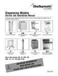
1
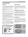
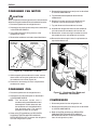
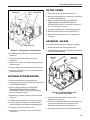
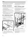
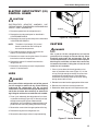
SERVICE
MANUAL
Versa Drawer
Refrigeration Units
MODELS:
F17VD84
F18VD50
F18VD82
F2984VDL
F2984VDR
Please read this manual
completely before attempting
to service this equipment.
1
Drawer
2
Drawer
1
Drawer
2
Drawer
1
Drawer
Drawer
3
2
Drawer
Drawer
4
18650VDL
18650VDR
18682VDL
18682VDR
RETAIN THIS MANUAL FOR FUTURE REFERENCE.
Delfield 980 S. Isabella Rd., Mt. Pleasant, MI 48858
(989) 773-7981 or (800) 733-8829 • Fax (989) 773-3210
www.delfield.com
February 2007
Delfield
IMPORTANT WARNINGS AND SAFETY INFORMATION
WARNING
ANY REFRIGERATION SERVICE PROCEDURES DESCRIBED IN THIS MANUAL MUST BE PERFORMED
BY A CERTIFIED EPA TECHNICIAN.
Read this manual thoroughly before installing, operating, or performing maintenance on the equipment.
FAILURE TO FOLLOW INSTRUCTIONS IN THIS MANUAL CAN CAUSE PROPERTY DAMAGE, INJURY OR DEATH.
•
Do not store or use gasoline or other flammable vapors or liquids in the vicinity of this or any other appliance.
•
Unless all covers and access panels are in place and properly secured, do not operate this equipment.
•
Damp or wet hands may stick to cold surfaces.
•
Allow heated equipment to cool down before attempting to clean or service.
•
Read and understand instruction manuals and labels. Learn all applications and restrictions for the
service performed.
•
Do not remove ground prong from service equipment cords.
•
Use extension cords rated for the intended service and as short in length as possible.
•
Use refrigerant hoses SAE J196-1992 approved with a shutoff device within 12 inches of the ends.
•
Make sure recovery tanks are DOT approved for use with the type of refrigerant being serviced.
•
Service units only in well ventilated areas using mechanical ventilation systems.
•
Follow all accessory advisories and instructions.
•
Do not operate any unit with defective or damaged parts.
WARNING
Serious injury or death can occur from inhaling high concentrations of refrigerant vapors. These vapors also
reduce oxygen levels in confined areas. Contact with liquid can cause frostbite. All containers, equipment and
hoses are under high pressure. Do not puncture or damage these components.
CAUTION
Observe the following:
• Keep the equipment area free and clear of combustible material.
• Maintain adequate clearance for air openings.
• Operate equipment only on the type of electricity indicated on the data plate.
• Unplug the unit before making any repairs.
• Handle all refrigerant hoses, recovery tanks, lines and other vessels as containers under pressure at all times.
• Retain this manual for future reference.
2
Versa Drawer Refrigeration Units
TABLE OF CONTENTS
IMPORTANT WARNINGS AND SAFETY INFORMATION ....................................................................... 2
INTRODUCTION ..................................................................................................................................... 5
GENERAL ........................................................................................................................................ 5
MODEL NUMBER ............................................................................................................................ 5
SERIAL NUMBER ............................................................................................................................ 5
HEATING SYSTEM .......................................................................................................................... 5
REFRIGERATION SYSTEM ............................................................................................................. 5
TEMPERATURE MONITORING ....................................................................................................... 5
CONTROLLER ................................................................................................................................. 5
SPECIFICATIONS ............................................................................................................................ 6
Refrigeration System .................................................................................................................. 6
Electrical Connections ............................................................................................................... 6
Drawers ...................................................................................................................................... 6
Legs ........................................................................................................................................... 6
Casters ...................................................................................................................................... 6
INSTALLATION ................................................................................................................................. 6
OPERATION ..................................................................................................................................... 6
OPERATOR MAINTENANCE ........................................................................................................... 6
COMPONENT REMOVAL AND REPLACEMENT ................................................................................... 7
COVERS AND PANELS ................................................................................................................... 7
Front Louvered Panel .................................................................................................................. 7
Louvered Access End Panel ...................................................................................................... 7
Rear Panel ................................................................................................................................. 7
DRAWER ASSEMBLY ...................................................................................................................... 7
Drawer Removal ......................................................................................................................... 7
Drawer Gasket ........................................................................................................................... 7
Drawer Front Assembly .............................................................................................................. 7
Return Air Baffle ......................................................................................................................... 8
Drawer Switch ............................................................................................................................ 8
EVAPORATOR COIL ASSEMBLY COVER ....................................................................................... 8
EVAPORATOR COIL ASSEMBLY .................................................................................................... 9
EXPANSION VALVE ......................................................................................................................... 9
CONDENSER FAN BLADE .............................................................................................................. 9
CONDENSER FAN MOTOR ........................................................................................................... 10
CONDENSER COIL ........................................................................................................................ 10
COMPRESSOR .............................................................................................................................. 10
ACCUMULATOR/RECEIVER .......................................................................................................... 11
FILTER DRYER .............................................................................................................................. 11
SOLENOID VALVES ...................................................................................................................... 11
PRESSURE TRANSDUCER ........................................................................................................... 12
BOX TEMPERATURE SENSOR ..................................................................................................... 12
3
Delfield
DISPLAY CONTROL BOARD ......................................................................................................... 12
ELECTRIC INPUT/OUTPUT (I/O) CONTROL BOARD .................................................................... 13
LEGS
.......................................................................................................................................... 13
CASTERS ...................................................................................................................................... 17
CONTROL CONSOLE ........................................................................................................................... 14
CHANGING DRAWER MODES ...................................................................................................... 14
MANUAL DEFROST ....................................................................................................................... 14
PROGRAM MENU .......................................................................................................................... 14
SET POINTS .................................................................................................................................. 15
CONFIGURATION .......................................................................................................................... 15
DIAGNOSTICS ............................................................................................................................... 15
TIME AND DATE ............................................................................................................................ 15
SOFTWARE VERSIONS ................................................................................................................ 15
TROUBLESHOOTING ........................................................................................................................... 16
GENERAL ...................................................................................................................................... 16
DIAGNOSTICS ............................................................................................................................... 16
TROUBLESHOOTING CHART ....................................................................................................... 16
CIRCUIT AND CONTROL DIAGRAMS ................................................................................................. 18
STANDARD LABOR GUIDELINES TO REPAIR OR REPLACE PARTS
ON DELFIELD EQUIPMENT ................................................................................................................ 23
MANUFACTURER'S LIMITED LIFETIME WARRANTY ......................................................................... 24
STANDARD ONE YEAR WARRANTY .................................................................................................... 25
ADDITIONAL FOUR YEAR PROTECTION PLAN (for Motor-Compressor only) ..................................... 26
4
Versa Drawer Refrigeration Units
INTRODUCTION
GENERAL
THAW SYSTEM
Versa Drawer series refrigeration units have two or four
drawers, each of which can operate in one of four modes
at any time. The two-drawer and four-drawer models
feature countertop-height stainless steel work surfaces.
A two-drawer Lo Profile unit is also available.
Hot gas is used for the thaw cabinet operation and the
defrost mode. A hot gas solenoid controls the heat. In the
defrost mode the hot gas will be used to warm the
evaporator coil when a drawer is used as a thaw cabinet.
The hot gas solenoid will open to maintain drawer
temperature.
Refrigeration mode: The drawer operates as a
refrigerator, maintaining the refrigeration set point
between 32°F and 41°F.
Freezer mode: The drawer operates as a self-defrosting
freezer, maintaining the freezer set point between -5°F
and 5°F.
Thaw Cabinet mode: The drawer operates as a thaw
cabinet, maintaining the thaw cabinet set point between
32°F and 50°F using hot gas and refrigeration as required
for a fixed time period. Once the period has elapsed, the
drawer mode is changed to refrigeration mode.
Convenience Chiller mode: The drawer operates as a
convenience chiller, maintaining the convenience chiller
set point between -5°F and 25°F for four hours. Once the
period has elapsed, the drawer mode is changed to
refrigeration mode.
All units have stainless steel exteriors and interiors. Drawer
gaskets are magnetic and mount to the drawer, snapping in
place. The gaskets are removable without tools.
This manual covers standard units. If you have a custom
unit, consult the service department at 800-733-8829.
REFRIGERATION SYSTEM
The refrigeration system is used in all modes. The
refrigeration solenoid controls refrigerant. Two compressors
run in parallel operation in a four-drawer system while one
compressor operates the two-drawer system.
TEMPERATURE MONITORING
Temperature sensors are located in each drawer. The
drawer temperature is displayed on the control panel.
CONTROLLER
The controller provides information indicating the drawer
mode. In addition, the actual temperature of the drawer is
displayed. The push button tabs, located next to the
display screen, represent each drawer. These tabs are
used to select the drawer for control. The control display
located on the right side of the control panel is used to
toggle between control screens and to select drawer
modes and temperatures.
SERIAL AND MODEL NUMBERS
The serial and model numbers are located inside
Drawer 1 on the left side.
Serial and Model Number
location
5
Delfield
SPECIFICATIONS
MODEL
NUMBER
VOLTS
HP
COMP
POS
AMPS
HEIGHT
(inches)
WIDTH
(inches)
DEPTH
(inches)
NO. OF
DRAWERS
SHIP
WGT
(lbs)
NEMA
PLUG
F18VD50
115
1/3
Left
6.0
36
50
31.5
2
520
5-15P
F18VD82
115
(2) 1/3
Left
12.0
36
82
31.5
4
720
5-15P
F17VD84
115
1/3
Left
6.0
36
84
31.5
2
750
5-15P
F2984VDL
115
1/3
Left
6.0
26
84
31.5
2
850
5-15P
F2984VDR
115
1/3
Right
6.0
26
84
31.5
2
850
5-15P
18650VDL
115
1/3
Left
6.0
34
50
31.5
2
520
5-15P
18650VDR
115
1/3
Right
6.0
34
50
31.5
2
520
5-15P
18682VDL
115
(2) 1/3
Left
12.0
34
82
31.5
4
720
5-15P
18682VDR
115
(2) 1/3
Right
12.0
34
82
31.5
4
720
5-15P
Refrigeration System
HFC-404A Refrigerant
INSTALLATION
Electrical Connections
See the Installation and Operation Manual for installation
information.
115 Volt, 60 Hertz, single phase, 3-wire, grounded, 8' cord
with plug
OPERATION
Drawers
32", 11-12 gauge stainless steel, 12" X 20" pan capacity
Legs
6" adjustable
Casters
5" casters, with and without brakes
6
See the Installation and Operation Manual for operational
information.
OPERATOR MAINTENANCE
See the Installation and Operation Manual for operator
maintenance information.
Versa Drawer Refrigeration Units
COMPONENT REMOVAL AND REPLACEMENT
Lo Profile and 2-Drawer refrigeration units use one
compressor, one accumulator, one receiver and four
solenoids. In addition, one evaporator is used for each
drawer along with support components. The 4-Drawer
refrigeration unit uses two complete 2-Drawer units.
Component removal and replacement is similar for
both types.
2. Lift louvered access end panel out and up to remove.
Perform the following procedures to remove and replace
parts. To eliminate mistakes when ordering parts, always
provide the following information:
2. Remove the rear panel from the unit.
• Model Number
DRAWER ASSEMBLY
3. Reverse the above steps to install the louvered
access end panel.
Rear Panel
1. While supporting the rear panel, remove 11 screws.
3. Reverse the above steps to install the rear panel.
• Serial Number
Drawer Removal
COVERS AND PANELS
Front Louvered Panel
NOTE:
1. Empty the drawer.
2. Pull and lift the drawer to remove it from the unit
(Figure 2).
Front louvered panel removal is similar
for all models.
1. Lift up on louver from bottom and pull away from
unit (Figure 1).
2. Reverse the above step to install the front
louvered panel.
Drawer
Figure 2. Drawer Removal
Drawer Gasket
The drawer gasket is installed on the inner side of the
drawer front and fitted into a slot (Figure 3).
Front louvered panel
Figure 1. Front Louvered Panel
1. Remove the drawer gasket by carefully pulling the
drawer gasket out of the groove.
2. Reverse the above step to install the drawer gasket.
Drawer Front Assembly
Louvered Access End Panel
1. Remove the drawer from the refrigeration unit (Figure 3).
NOTE:
2. Place the drawer on a solid surface with the drawer
front assembly down.
Louvered access end panel removal
is similar for all models.
1. While supporting the louvered access end panel,
remove mounting screws.
3. Remove six screws securing the drawer front
assembly to the drawer.
4. Reverse the above steps to install the drawer front
assembly.
7
Delfield
Drawer
switch
Figure 5. Drawer Switch
Screw
Drawer
gasket
Drawer
front
Figure 3. Drawer Front Assembly
Return Air Baffle
1. Remove screws from return air baffle (Figure 4).
4. Tag and disconnect the wiring harness from the
drawer switch.
5. Reverse the above steps to install a replacement
drawer switch.
EVAPORATOR COIL
ASSEMBLY COVER
NOTE:
Evaporator coil assembly cover
removal is similar for all models.
2. Remove blue wires from drawer switch while
supporting air baffle.
1. The evaporator coil assembly cover is mounted
behind the drawer (Figure 6).
3. Reverse the above steps to install the return air baffle.
2. Reach inside the box and remove four screws from
the front of the evaporator coil assembly cover.
Return air
baffle
6 Screws
Figure 4. Return Air Baffle
Drawer Switch
1. Disconnect power from the refrigeration unit.
Evaporator coil assembly
Evaporator coil assembly cover
Figure 6. Evaporator Coil Assembly Cover
2. Remove the drawer as described previously.
3. Reach inside the box and carefully remove the
drawer switch out of the mounting slot (Figure 5).
3. Tag and disconnect the fan electrical connectors.
4. Remove the evaporator coil assembly cover from
the box.
5. Reverse the above steps to install the evaporator
coil assembly cover.
8
Versa Drawer Refrigeration Units
EVAPORATOR COIL ASSEMBLY
1. Disconnect power from the refrigeration unit.
2. Remove the drawer as described above.
3. Remove the rear panel as described in COVERS
AND PANELS.
4. Remove the evaporator coil assembly cover as
described previously.
5. Follow the EPA guidelines for RECOVERY,
PURGING/TESTING AND RECHARGING
REFRIGERATION UNIT to recover the refrigerant
from the refrigeration system.
Screw
Evaporator coil
assembly
Thermocouple
Expansion
valve (TXV)
Figure 8. Expansion Valve and Thermocouple
4. Reach inside the drawer box and unsolder the
refrigeration lines. Remove the expansion valve and
thermocouple from the evaporator housing (Figure 8).
5. Reverse the above steps to install a replacement
expansion valve.
CONDENSER FAN BLADE
Screw
Evaporator coil assembly
Figure 7. Evaporator Coil Assembly Removal
1. Disconnect power from the refrigeration unit.
2. Remove the louvered access end panel as
described in COVERS AND PANELS.
6. From the rear of the refrigeration unit, unsolder the
refrigeration lines from the evaporator coil assembly.
7. Carefully remove the expansion valve thermocouple
from evaporator line.
8. Remove the evaporator coil assembly from the unit
(Figure 7).
9. Reverse the above steps to install a replacement
or repaired evaporator coil assembly. Recharge the
system as described in the EPA guidelines for
RECOVERY, PURGING/TESTING AND
RECHARGING REFRIGERATION UNIT.
Nut
Condenser
fan blade
EXPANSION VALVE
Figure 9. Condenser Fan Blade
1. Disconnect power from the refrigeration unit.
2. Remove the evaporator coil assembly cover as
described in COVERS AND PANELS.
3. Remove the expansion valve thermocouple from the
evaporator line.
3. While holding the condenser fan blade (Figure 9),
remove the lock nut from the center of the
condenser fan blade.
4. Reverse the above steps to install the condenser
fan blade.
9
Delfield
CONDENSER FAN MOTOR
5. Tag and remove the temperature sensor from the
condenser coil.
CAUTION
Make sure power to the refrigeration unit is disconnected
before servicing the condenser fan and condenser fan motor.
1. Disconnect power from the refrigeration unit.
2. Remove the louvered access end panel as described
in COVERS AND PANELS.
3. Tag and disconnect the wiring harness at the
condenser fan motor.
4. Remove the condenser fan blade as described above.
Condenser
fan motor
4. Remove the louvered access end panel as described
in COVERS AND PANELS.
6. Remove six screws securing the condenser coil
inside the machine compartment (Figure 11).
7. Tag and disconnect the condenser fan motor.
8. Unsolder the refrigeration lines from the condenser
coil and remove the condenser coil from the unit.
9. Remove four screws securing the condenser coil to
the condenser cover and condenser fan bracket.
10. Reverse the above steps to install a replacement or
repaired condenser coil.
Condenser
fan bracket
Screw
Condenser
fan bracket
Figure 10. Condenser Fan Motor
Screw
Condenser
cover
Condenser
coil
5. While supporting the condenser fan motor, remove
three screws securing the condenser fan motor to
the condenser fan bracket (Figure 10).
6. Reverse the above steps to install a replacement
condenser fan motor.
CONDENSER COIL
1. Disconnect power from the refrigeration unit.
Figure 11. Condenser Fan Blade and
Condenser Fan Bracket
2. Remove the front louvered panel as described in
COVERS AND PANELS.
NOTE:
The two-drawer system uses a
condenser coil mounted behind the front
louvered panel. The four-drawer unit uses
two condenser coils stacked behind the
front louvered panel. The removal
procedure is similar for all models.
3. Refer to the EPA guidelines for RECOVERY,
PURGING/TESTING AND RECHARGING
REFRIGERATION UNIT to recover the refrigerant
from the refrigeration system.
10
COMPRESSOR
1. Disconnect power from the refrigeration unit.
2. Remove the louvered access end panel as described
in COVERS AND PANELS.
3. Refer to the EPA guidelines for RECOVERY,
PURGING/TESTING AND RECHARGING
REFRIGERATION UNIT to recover the refrigerant
from the refrigeration system.
Versa Drawer Refrigeration Units
FILTER DRYER
Accumulator
Filter
dryer
Compressor
1. Disconnect power from the refrigeration unit.
2. Remove the louvered access end panel as described
in COVERS AND PANELS.
Receiver
3. Refer to the EPA guidelines for RECOVERY,
PURGING/TESTING AND RECHARGING
REFRIGERATION UNIT to recover the refrigerant
from the refrigeration system.
4. Unsolder the refrigerant line at the filter dryer (Figure 12).
5. Remove the filter dryer from the refrigeration unit.
6. Reverse the above steps to install a replacement
filter dryer.
SOLENOID VALVES
Rubber mounts
All solenoid valves are identical. Remove as follows:
1. Disconnect power from the refrigeration unit.
Figure 12. Refrigeration Compartment
2. Remove the louvered access end panel as described
in COVERS AND PANELS.
4. Unsolder the refrigeration lines at the compressor
(Figure 12).
5. Tag and disconnect the wiring harness at the
compressor.
Solenoid
valves
Pressure
transducer
6. Remove four screws securing the compressor to the
refrigeration unit.
7. Remove compressor and four isolation rubber mounts.
8. Reverse the above steps to install a replacement or
repaired compressor.
ACCUMULATOR/RECEIVER
1. Disconnect power from the refrigeration unit.
2. Remove the louvered access end panel as described
in COVERS AND PANELS.
3. Refer to the EPA guidelines for RECOVERY,
PURGING/TESTING AND RECHARGING
REFRIGERATION UNIT to recover the refrigerant
from the refrigeration system.
4. Remove the insulation jacket from the accumulator
(Figure 12).
5. Unsolder the refrigeration lines at the accumulator.
6. Reach underneath refrigeration unit and remove one
screw securing the accumulator to the refrigeration unit.
7. Remove the accumulator from the unit.
Figure 13. Solenoid Valves and
Pressure Transducer
3. Tag and disconnect the wiring harness at the
solenoid valve (Figure 13).
4. To check or remove the solenoid coil, remove the nut
securing the solenoid coil on the solenoid valve.
Remove the solenoid coil and wiring harness.
5. Unsolder the refrigeration lines at the solenoid valve.
8. Reverse the above steps to install a replacement
accumulator.
11
Delfield
6. Remove the solenoid valve from the refrigeration unit.
7. Reverse the above steps to install a replacement
solenoid coil or replacement solenoid valve.
PRESSURE TRANSDUCER
1. Disconnect power from the refrigeration unit.
2. Remove the louvered access end panel as described
in COVERS AND PANELS.
3. Tag and disconnect the wiring harness from the
pressure transducer (Figure 13).
4. While holding pressure transducer mount, use pliers
to remove the pressure transducer from the Schrader
access valve.
5. Reverse the above steps to install a replacement
pressure transducer. Apply leak lock to the pressure
transducer threads before installation.
6. Remove the temperature sensor mounting screw and
remove the box temperature sensor from the rear.
7. Reverse the above steps to install a replacement
box temperature sensor.
DISPLAY CONTROL BOARD
1. Disconnect power from the refrigeration unit.
2. Remove the louvered access end panel as described
in COVERS AND PANELS.
3. Remove the front louvered panel as described in
COVERS AND PANELS.
4. Inside the machine compartment, tag and
disconnect the wiring harness from the display
control board (Figure 15).
Display
control board
BOX TEMPERATURE SENSOR
Nut
1. Disconnect power from the refrigeration unit.
Lock
washer
2. Remove the drawer as described previously.
3. Remove the rear panel as described in COVERS
AND PANELS.
4. Reach inside the box and remove the temperature
sensor mounting screw (Figure 14).
Rear panel
Box temperature
sensor
Screw
Electric I/O
control board
Figure 15. Control Boards
Temperature sensor
mounting screw
Figure 14. Box Temperature Sensor
5. Tag and disconnect the wiring harness from the box
temperature sensor.
12
5. Remove four nuts and four lock washers from the
display control board.
6. Carefully remove the display control board from the
machine compartment.
7. Reverse the above steps to install a replacement
display control board.
Versa Drawer Refrigeration Units
ELECTRIC INPUT/OUTPUT (I/O)
CONTROL BOARD
CAUTION
ELECTROSTATIC SENSITIVE ASSEMBLY; USE
PRECAUTIONARY PROCEDURES WHEN HANDLING
CIRCUIT CARD ASSEMBLIES.
Screws
1. Disconnect power from the refrigeration unit.
2. Remove the front louvered panel as described in
COVERS AND PANELS.
3. Remove the louvered access end panel as described
in COVERS AND PANELS.
NOTE:
The electric input/output (I/O) control
board is mounted on the inside top of
the machine compartment.
4. Tag and disconnect the wiring harness from the
electric I/O control board (Figure 16).
5. Remove four screws securing the electric I/O control
board to the machine compartment.
6. Remove the electric I/O control board from the
refrigeration unit.
7. Reverse the above steps to install a replacement
electric I/O control board.
LEGS
DANGER
Use a jack to lift the refrigeration unit off the ground
just far enough to remove the leg. Place blocking
underneath the refrigeration unit. Do not work
underneath a raised unit without proper blocking. Do
not lift the unit more than necessary to remove the
leg. Lifting the unit too far can make the unit unstable.
Figure 16. Leg Removal
CASTERS
DANGER
Use a jack to lift the refrigeration unit off the
ground just far enough to remove the leg. Place
blocking underneath the refrigeration unit. Do
not work underneath a raised unit without proper
blocking. Do not lift the unit more than necessary
to remove the caster. Lifting the unit too far can
make the unit unstable.
1. Place a jack underneath the refrigeration unit as
close as possible to the caster (Figure 17). Lift the
unit up just high enough to remove the caster from
underneath the refrigeration unit. Place blocking
underneath the unit to prevent the unit from falling
during removal of the caster.
2. Remove four screws from the upper portion of the caster.
3. Remove the caster from the refrigeration unit.
4. Reverse the above steps to install a replacement caster.
1. Place a jack underneath the refrigeration unit as close
as possible to the leg (Figure 16). Lift the unit just high
enough to remove the leg from underneath the
refrigeration unit. Place blocking underneath the unit to
prevent the unit from falling during removal of the leg.
2. Remove four screws from the upper portion of the leg.
3. Remove the leg from the refrigeration unit.
Screws
4. Reverse the above steps to install a replacement leg.
Figure 17. Caster Removal
13
Delfield
CONTROL CONSOLE
The control console contains the data display and control
buttons (Figures 18 and 19) needed to operate the drawers.
The menus can be accessed by pressing and holding the
i (Enter) button for approximately 5 seconds. The various
screens used to monitor unit operation and to change
settings will time out after 30 seconds. The exception is
the diagnostics screen which does not time out.
UP
1
Drawer
Drawer
3
2
Drawer
Drawer
4
LEFT
(BACK)
Figure 20. Drawer Mode Display
(2-Drawer Display shown)
ENTER
CAUTION
Only qualified technicians should access the following
programming menus.
DOWN
RIGHT
MANUAL DEFROST
NOTE:
Figure 18. 4-Drawer Console Display
UP
ENTER
Both buttons must be pressed within
one second to manually set defrost.
To manually set a drawer to defrost, press the desired drawer
tab (Figure 20) and then very quickly press i (Enter). To turn
off manual defrost, press the desired drawer tab and very
quickly press i (Enter).
PROGRAM MENU
NOTE:
LEFT
(BACK)
DOWN
RIGHT
At any time while using the control, go
back to the previous screen by
pressing the LEFT arrow.
The Program Menus can be accessed by pressing and
holding i (Enter) for five seconds.
Figure 19. 2-Drawer Console Display
CHANGING DRAWER MODES
NOTE:
At anytime while using the control,
go back to the previous screen by
pressing the LEFT arrow.
1. Press the desired drawer tab on the display.
Figure 21. Program Menu
(2-Drawer Display Shown)
2. Press the UP or DOWN arrows to the desired mode
(Refrigerate, Freeze, Chill, or Thaw) (Figure 20).
1. Select the desired function by pressing the UP or
DOWN arrows (Figure 21).
NOTE:
2. Press i (Enter) to select the function.
The desired mode will display with
parenthesis when selected.
3. Press the drawer tab again to lock the desired
mode setting.
14
Versa Drawer Refrigeration Units
SET POINTS
DIAGNOSTICS
Once in the Program Menu press the UP or DOWN arrows
to Set Points and press i (Enter) (Figure 22).
Once in the Program Menu press the UP or DOWN arrows
to Diagnostics and press i (Enter) for diagnostics display
(Figure 24).
2. Press i (Enter) to lock in the desired temperature setting.
CONFIGURATION
Once in the Program Menu press the UP or DOWN arrows
to Configuration and press i (Enter) (Figure 23).
3
Drawer
4
Figure 24. Diagnostics Menu
(4-Drawer Display Shown)
Figure 22. Set Points Menu
(2-Drawer Display Shown)
1. Select a function from the Set Points menu by
pressing the UP or DOWN arrows to the desired
function and press i (Enter). This selection will allow
the temperature setting to be adjusted.
Drawer
TIME AND DATE
Once in the Program Menu press the UP or DOWN arrows
to Time & Date and press i (Enter) allowing the time and
date to display.
1. Adjust the time and date by pressing the RIGHT
arrow to the desired digit location and the UP or
DOWN arrow to the proper digit.
2. Press i (Enter) to lock in the setting.
3. Repeat for each digit location on the screen.
4. When completed press i (Enter) then the LEFT arrow
to exit the Time and Date screen.
SOFTWARE VERSIONS
Figure 23. Configuration Menu
(2-Drawer Display Shown)
Once in the Program Menu press the UP or DOWN arrows
to SW Versions (Figure 25) and press i (Enter) allowing the
software versions to display.
1. Select a function from the Configuration Menu by
pressing the UP or DOWN arrows to the desired
function and pressing i (Enter) allowing the function
to be adjusted or viewed.
• Mode: System temperature set points differential
• Defrost: Defrost times and set points
• Compressor: Compressor run times
• Condenser: Condenser temperatures and run times
• System: Drawer open timeout, data log interval, run
frame heaters, metric, language, reload defaults
Figure 25. Software Versions Display
(2-Drawer Display Shown)
NOTE:
The software versions in Figure 25
are shown as examples only and are
not the actual software versions.
2. Press i (Enter) to lock in an adjusted setting or
press the LEFT arrow to go back.
15
Delfield
TROUBLESHOOTING
GENERAL
DIAGNOSTICS
The troubleshooting chart below provides common
symptoms, causes and remedies. The chart cannot
cover every problem that may occur. However, the
most common problems, as shown in the table, can be
used to troubleshoot many symptoms. The chart used
in conjunction with the diagnostics screen provides
good troubleshooting information.
The diagnostics screen as described above provides an
ongoing display of drawer data. The diagnostics screen
does not time out but remains available for observation by
a service technician. This screen can be accessed as
described above.
TROUBLESHOOTING CHART
SYMPTOM
CAUSE/REMEDY
Unit does not run.
Make sure the unit is plugged into a proper power source.
Check for a blown fuse or tripped breaker.
Test the outlet for the correct voltage (120V).
Inspect the electrical cord for damage.
Unit has power but does not run.
Check for power at the junction box inside the compressor compartment.
Check for power coming out of the control board (12VDC) at the terminal for
the control board.
If no power is coming out of the control board, replace the control board.
Compressor does not run
but the fan works.
Check voltage from the control board.
Make certain there is ample air flow for the evaporator and condenser coils.
Clean the condenser coils.
Test the compressor relays for overload.
Test the compressor for open or shorted windings.
Check control settings and make sure the control is calling for the fans to run.
Evaporator fans do not run.
Check for voltage (12VDC) at the fan motors.
Check for obstructions to the fan blade.
Check to see if the door switch is open or is shorted out.
Check control settings and make sure the control is calling for the fans to run.
Condenser fans do not run.
Check for voltage (12VDC) at the fan motors.
Check for obstructions to the fan blade.
Check control settings and make sure the control is calling for the fans to run.
Check the temperature sensor in the condenser coil to see if it is open or shorted.
Unit is not reaching desired
temperature.
Check to see that the unit is in the correct mode of operation.
Check to see that the unit is set at the desired set point.
Check to see if the box temperature sensor is open or shorted.
Listen to determine if the compressor is cycling or if the unit is continuously running.
Check evaporator air flow.
Check for ice buildup on the evaporator coils.
Check the drawers and gaskets to ensure they seal properly.
Unit is getting too cold.
Check to see that the unit is in the correct mode of operation.
Check to determine that the unit is set at the desired set point.
Check to determine if the box temperature sensor is open or shorted.
Listen to determine if the compressor is cycling or if the unit is
continuously running.
16
Versa Drawer Refrigeration Units
SYMPTOM
CAUSE/REMEDY
Unit is noisy.
Check for loose or broken fan blades.
Check for ice buildup on the evaporator coil.
Inspect the compressor mounts.
Check for loose or missing screws on the compressor compartment louvers.
Unit runs continuously.
Clean the condenser coils.
Check the drawer gaskets.
Check to determine if the box temperature sensor is open or shorted.
Check refrigerant charge.
Check the compressor.
Check the evaporator fans.
Unit short cycles.
Check the drawer gaskets.
Check to determine if the box temperature sensor is open or shorted.
Check refrigerant charge.
Check the compressor.
Check condenser fans.
Check TXV.
Unit evaporator coils are
freezing up.
Clean the condenser coils.
Check the drawer gaskets.
Check to determine if the box temperature sensor is open or shorted.
Check refrigerant charge.
Check the evaporator fans and air flow.
Check to assure that the hot gas loop is more than 1 inch away from
either end of the evaporator drain pan.
Check the TXV.
Water on floor outside the unit.
Check the evaporator drain pan and drain lines.
Check the condensate drain pan.
Make sure the condensate wicks are not missing.
Water inside the unit.
Check the evaporator drain pan and drain lines.
Verify proper condensate removal.
Verify proper condensate pan installation.
Unit is showing “Drawer Open”
on the display.
Close drawer.
Check drawer switch.
Check control.
Unit is showing “Out of
Temperature Range” on
the display.
Check to determine that the unit is in the correct mode of operation.
Check to determine that the unit is set at the desired set point.
Check to determine if the box temperature sensor is open or shorted.
Check to determine if any drawers are open.
The unit has power but
the display is not lit.
Check voltage at the display plug on the control.
If there is voltage at the display plug on the control board, replace the
display board.
If there is not voltage at the display plug on the control board, replace the
control board.
Unit alarm is sounding
after losing power.
Press the i (Enter) button on the display once to make the alarm quit. This
will then show on the display the time that the unit last had power and
the time that the unit had power restored. Press the i (Enter) button
again to show the main display screen.
Unit alarm is sounding –
compressor is failing.
Check the unit pressures.
Check the suction line pressure transducer.
17
Delfield
CIRCUIT AND CONTROL DIAGRAMS
COND. OUTLET
TEMP. SENSOR
REFG. SOL.
S
(2) 12V DC
AXIAL FANS
TXV
DEFROST
TEMP.
SENSOR
ACCESS
PORT
HOT GAS SOL.
S
COND. COIL
RECEIVER
FILTER/
DRYER
COND.
TEMP.
SENSOR
REFG. SOL.
S
HOT GAS SOL.
S
ACCESS
PORT
PRESSURE
TRANSDUCER
EVAP. COIL
(2) 12V DC
AXIAL FANS
TXV
REFG. BOX 1
DEFROST
TEMP.
SENSOR
EVAP. COIL
BOX
TEMP.
SENSOR
REFG. BOX 2
1/3
HP
COMPRESSOR
ACCUMULATOR
THIS REPRESENTS A 2-DRAWER SYSTEM.
4-DRAWER UNIT IS COMPRISED OF TWO (2)
2-DRAWER SYSTEMS OPERATED BY ONE CONTROL.
Refrigeration Schematic
18
BOX
TEMP.
SENSOR
Versa Drawer Refrigeration Units
BOARD CONNECTOR MAP
1 – +12V FOR D1 AND D2 FANS
2 – D1 FANS RETURN
3 – D2 FANS RETURN
4 – +12V FOR D3 AND D4 FANS
5 – D3 FANS RETURN
6 – D4 FANS RETURN
POWER TO
DISPLAY BOARD
1 – +8V
2 – GROUND
I/O TO DISP.
1 TO 1
2 TO 2
85–265 VAC
50/60 HZ
CONTROL POWER
1
J18
1 – COMMON FOR D1 AND
D2 DRW SWITCHES
2 – D1 SWITCH
3 – D2 SWITCH
4 – COMMON FOR D3 AND
D4 DOOR SWITCHES
5 – D3 SWITCH
6 – D4 SWITCH
1
4
I/O BOARD
J19
J23
1
J22
J31
1
J29
TEMPERATURE SENSORS
COMMUNICATION CABLE
TO DISPLAY BOARD
I/O TO DISP.
1 TO 1
2 TO 2
3 TO 3
PREFER SHIELDED
TWISTED PAIR.
1 AND 2 TWISTED,
3 SHIELD.
1
1
J11
J1 J2 J3 J4
BOX COIL BOX COIL
D1
D2
SUCTION
PRESSURE
TRANSDUCER
1 – +5V
2 – SIGNAL
3 – COMMON
J30
J9 J10 J36 J35
BOX COIL BOX COIL
COND 1
COND 2
J34 J11
1
SP2
1
SP1
J30
1 – D3 FRAME HEATER
2 – NC
3 – D4 FRAME HEATER
J25–AC HOT
FOR ALL AC LOADS
J5 J6 J7 J8
BOX COIL BOX COIL
D3
D4
J29
1 – D1 FRAME HEATER
2 – NC
3 – D2 FRAME HEATER
J26 J24 J25
J32 J33
COMP 2
COMP 1
AC HOT
2
1
COND FAN
J28
1
D3 & D4 VALVES
J27
1
D1 & D2 VALVES
J27
1 – D1
2 – D1
3 – D2
4 – D2
REFG. SOLENOID
HOT GAS SOLENOID
REFG. SOLENOID
HOT GAS SOLENOID
J28
1 – D3
2 – D3
3 – D4
4 – D4
REFG. SOLENOID
HOT GAS SOLENOID
REFG. SOLENOID
HOT GAS SOLENOID
Versa Drawer Electric Input/Output (I/O) Control Board Connector Map
19
20
L1
G
N
CONTROL
POWER
DISP. TO I/O
1 TO 1
2 TO 2
3 TO 3
PREFER SHIELDED TWISTED
PAIR. 1 AND 2 TWISTED,
3 SHIELD.
COMMUNICATION CABLE
TO I/O BOARD
1
COIL
COIL
BOX
IN
J10
BOX
J7
BOX
J3
1
COND 1
OUT
J9
J6
J5
D3
J2
BOX
D1
J1
J11
J19
J18
J2
IN
J35
J1
COND 2
OUT
J36
COIL
J8
COIL
J4
D4
D2
1
J23
1
SP2
J34
1
SP1
J11
1
26
COMP 2
J26
24
AC HOT
J24
25
COMP 1
J25
J33
32
33
2
1
CONDFAN
J32
SEE BOARD CONNECTOR
FOR PIN CONNECTION DETAILS
I/O BOARD
POWER TO I/O BOARD
1 – +8V
2 – GROUND
DISP. TO I/O
1 TO 1
2 TO 2
DISPLAY BOARD
2 5
1
14 18 13 17
D3 & D4VALVES
J28
J22
1 4
1
4
3 6
1
J30
12 16 11 15
D1 & D2VALVES
1112
J29
J31
J27
1
9 10
7 8
1
1
37
36
35
34
2
1
34
7
MTR
MTR
EVAP.TEMP.
PROBE
BOX TEMP.
PROBE
DRAWER R
FAME
HEATER
DRAWER LIMIT
8 SWITCH
12 VDC
EVAP. FANS
BOX 1
3
1
35
7
9
MTR
MTR
EVAP.TEMP.
PROBE
BOX TEMP.
PROBE
DRAWER R
FAME
HEATER
DRAWER LIMIT
SWITCH
12 VDC
EVAP. FANS
BOX 2
4
5
36
11
10
MTR
MTR
EVAP.TEMP.
PROBE
BOX TEMP.
PROBE
DRAWER R
FAME
HEATER
DRAWER LIMIT
SWITCH
12 VDC
EVAP. FANS
BOX 3
6
4
37
10
12
MTR
MTR
EVAP.TEMP.
PROBE
BOX TEMP.
PROBE
DRAWER R
FAME
HEATER
DRAWER LIMIT
SWITCH
12 VDC
EVAP. FANS
BOX 4
Delfield
Versa Drawer 4-Drawer Wiring Diagram (1 of 2)
Versa Drawer Refrigeration Units
POWER TO
DISPLAY BOARD
1 – +8V
2 – GROUND
I/O TO DISP.
1 TO 1
2 TO 2
BOARD CONNECTOR MAP
1
1 – COMMON FOR D1 AND D2 DRW SWITCHES
2 – D1 SWITCH
3 – D2 SWITCH
4 – COMMON FOR D3 AND D4 DOOR SWITCHES
5 – D3 SWITCH
6 – D4 SWITCH
1
4
J18
I/O BOARD
J19
J23
J31
1
J22
J29
1 – D1 FRAME HEATER
2 – NC
3 – D2 FRAME HEATER
1
J29
TEMPERATURE SENSORS
J11
J1
J2
J3
COIL
BOX
J4
COIL
BOX
J5
J7
J6
BOX
COIL
BOX
J9
J10
COIL
J36
COIL
J34
J35
J11
1
COIL
J26
1
SP2
J24
COMP 2
J25
J32
COMP 1
J28
J33
J27
1
2
1
CONDFAN
AC HOT
J28
1 – D3 REFG. SOLENOID
2 – D3 HOT GAS SOLENOID
3 – D4 REFG. SOLENOID
4 – D4 HOT GAS SOLENOID
1
D3 & D4VALVES
D1 & D2VALVES
13
17
SP1
REFG. SOLENOID
HOT GAS SOLENOID
REFG. SOLENOID
HOT GAS SOLENOID
NSK
PRESSURE
TRANSDUCER
FORCOMP. 2
BLACK (COM)
WHITE (VOUT)
MTR
MTR
26
RED (VDC IN)
BLACK (COM)
WHITE (VOUT)
COMPRESSOR 2
COND. FAN 2
32
COND. IN 1
TEMP. PROBE
COND. OUT 1
TEMP. PROBE
MTR
NSK
PRESSURE
TRANSDUCER
FOR COMP 1
RED (VDC IN)
25
COND. FAN 1
MTR
33
18
COMPRESSOR 1
REFG
.
SOLENOID
HOT GAS
SOLENOID
HOT GAS
SOLENOID
BOX
COND 2
REFG
.
SOLENOID
DRAWER 3
DRAWER 4
14
16
REFG
.
SOLENOID
REFG
.
SOLENOID
HOT GAS
SOLENOID
11
15
COND 1
DRAWER 1
J27
1 – D1
2 – D1
3 – D2
4 – D2
D4
BOX
HOT GAS
SOLENOID
J25–AC HOT
FOR ALL AC LOADS
J8
D3
DRAWER 2
J30
D2
D1
12
J30
1 – D3 FRAME HEATER
2 – NC
3 – D4 FRAME HEATER
1
SUCTION
PRESSURE
TRANSDUCER
1 – +5V
2 – SIGNAL
3 – COMMON
1
COND. OUT 2
TEMP. PROBE
COMMUNICATION CABLE
TO DISPLAY BOARD
I/O TO DISP.
1 TO 1
2 TO 2
3 TO 3
PREFER SHIELDED
TWISTED PAIR.
1 AND 2 TWISTED,
3 SHIELD.
COND. IN 2
TEMP. PROBE
85–265 VAC
50/60 HZ
CONTROL POWER
1 – +12V FOR D1 AND D2 FANS
2 – D1 FANS RETURN
3 – D2 FANS RETURN
4 – +12V FOR D3 AND D4 FANS
5 – D3 FANS RETURN
6 – D4 FANS RETURN
Versa Drawer 4-Drawer Wiring Diagram (2 of 2)
21
22
L1
G
N
CONTROL
POWER
TO I/O BOARD
DISP. TO I/O
1 TO 1
2 TO 2
3 TO 3
PREFER SHIELDED TWISTED
PAIR. 1 AND 2 TWISTED,
3 SHIELD.
COMMUNICATION CABLE
SEE BOARD CONNECTOR
FOR PIN CONNECTION DETAILS
I/O BOARD
POWER TO I/O BOARD
1 – +8V
2 – GROUND
DISP. TO I/O
1 TO 1
2 TO 2
DISPLAY BOARD
BOX 1
BOX 2
Delfield
Versa Drawer 2-Drawer Wiring Diagram (1 of 2)
COMMUNICATION CABLE
TO DISPLAY BOARD
I/O TO DISP.
1 TO 1
2 TO 2
3 TO 3
PREFER SHIELDED
TWISTED PAIR.
1 AND 2 TWISTED,
3 SHIELD.
85–265 VAC
50/60 HZ
CONTROL POWER
SUCTION
PRESSURE
TRANSDUCER
1 – +5V
2 – SIGNAL
3 – COMMON
TEMPERATURE SENSORS
J25–AC HOT
FOR ALL AC LOADS
I/O BOARD
BOARD CONNECTOR MAP
POWER TO
DISPLAY BOARD
1 – +8V
2 – GROUND
I/O TO DISP.
1 TO 1
2 TO 2
1 – +12V FOR D1 AND D2 FANS
2 – D1 FANS RETURN
3 – D2 FANS RETURN
4 – +12V FOR D3 AND D4 FANS
5 – D3 FANS RETURN
6 – D4 FANS RETURN
DRAWER 1
J27
1 – D1
2 – D1
3 – D2
4 – D2
J28
1 – D3
2 – D3
3 – D4
4 – D4
REFG. SOLENOID
HOT GAS SOLENOID
REFG. SOLENOID
HOT GAS SOLENOID
REFG. SOLENOID
HOT GAS SOLENOID
REFG. SOLENOID
HOT GAS SOLENOID
J30
1 – D3 FRAME HEATER
2 – NC
3 – D4 FRAME HEATER
J29
1 – D1 FRAME HEATER
2 – NC
3 – D2 FRAME HEATER
1 – COMMON FOR D1 AND D2 DRW SWITCHES
2 – D1 SWITCH
3 – D2 SWITCH
4 – COMMON FOR D3 AND D4 DOOR SWITCHES
5 – D3 SWITCH
6 – D4 SWITCH
DRAWER 2
Versa Drawer Refrigeration Units
Versa Drawer 2-Drawer Wiring Diagram (2 of 2)
23
Delfield
STANDARD LABOR GUIDELINES TO REPAIR OR REPLACE
PARTS ON DELFIELD EQUIPMENT UNDER WARRANTY
Advice and recommendations given by Delfield Service
Technicians do not constitute or guarantee any special
coverage.
A maximum of 1 hour is allowed to diagnose a defective
component.
A maximum of 1 hour is allowed for retrieval of parts not
in stock.
A maximum travel distance of 100 miles round trip and
2 hours will be reimbursed.
Overtime, installation/start-up, normal control
adjustments, general maintenance, glass breakage,
freight damage, and/or correcting an end-user installation
error will not be reimbursed under warranty unless preapproved with a Service Work Authorization from Delfield.
You must submit the number with the service claim.
LABOR OF 1 HOUR IS ALLOWED TO REPLACE:
• Solenoid Coil
• Evaporator/Condenser Fan Motor and Blade
• Hi-limit/Thermal Protector Switch
• Door Hinges, Locks and Gaskets
• Compressor Start Components and Overload
Protector
LABOR OF 2 HOURS TO REPLACE:
• Drawer Tracks/Cartridges
• Solenoid Valve
• Pressure Control
• Locate/Repair
• Microprocessor Control
LABOR OF 3 HOURS TO REPLACE:
• Expansion Valve
• Condenser or Evaporator Coil
LABOR OF 4 HOURS TO REPLACE:
Compressor
Refrigerants
This includes recovery of refrigerant and leak check.
R404A A maximum of $12.00/lb. or 75¢/oz.will be
reimbursed.
$55.00 maximum reimbursement for refrigerant recovery
(includes recovery machine, pump, torch, oil, flux, minor
fittings, solder, brazing rod, nitrogen, or similar fees.)
24
Versa Drawer Refrigeration Units
MANUFACTURER'S LIMITED LIFETIME WARRANTY
Delfield warrants to the original purchaser-user, subject to
the limitations and exclusions set forth below, that the
ABS interior of the Delfield models identified above will be
free of manufactured defects for as long as the equipment
is owned by the original purchaser-user and is in operation.
to Delfield within 15 days after the date of service to be
eligible for warranty coverage. All claims must include the
model, serial number, an original date of installation and
customer identification. Use of parts other than original
Delfield replacement parts will not be covered.
Exclusions
What is covered
For purposes of this Warranty, interior liner is defined as
the portion of the interior liner which is made of ABS
material. This Warranty applies only to products sold and
installed after March 1, 2000 in the United States, Canada,
Puerto Rico, and Mexico. For purposes of this Warranty,
lifetime is defined as the expected usable life for the
equipment of 12 years.
This warranty does not cover labor, service, charges for
travel time, mileage, or premium charges. This warranty
also does not include defects resulting from:
Operation of the product beyond the specification set forth
in the Service and Installation Manual.
Failure to clean and maintain the product as described in
the Service and Installation Manual.
Installation of the product in a manner other than as set
forth in the Service and Installation.
Delfield’s Obligation
Limited strictly to shipping OEM replacement parts or
repair kits for any ABS covered interior. A Delfield
authorized service dealer and Delfield’s Service Department
must confirm the liner defect has occurred under normal
conditions and is not due to misuse as defined below. All
decisions regarding the ABS interior shall be made by
Delfield’s Service Department and shall be binding upon
the parties. No labor or service charges or allowances are
covered by this warranty. Warranty service must be
performed by a Delfield approved authorized service
agent.
User Responsibility
The product must be installed, cleaned and maintained as
described in the Installation & Operation manual which is
furnished with the product. Only approved replacement
parts may be used. Failure to adhere to the requirements
of this paragraph may void warranty coverage.
Procedures
All claims for replacement parts or repair kits must be
made through a Delfield Parts Depot or an authorized
Delfield dealer. The defective part invoice must be returned
Use or installation of replacement parts not approved by
Delfield: or The introduction of hot items directly onto the
ABS liner.
This warranty is in lieu of all other warranties or
guarantees of any kind, express or implied, except
Delfield’s One Year Parts and 90-Day Warranty 4400
Series. ANY IMPLIED WARRANTIES OR
MERCHANTABILITY OR FITNESS FOR A PARTICULAR
PURPOSE ARE HEREBY DISCLAIMED AND
EXCLUDED. IN NO EVENT SHALL DELFIELD BE
LIABLE FOR INCIDENTAL OR CONSEQUENTIAL
DAMAGES OF ANY KIND OR NATURE, OR FOR ANY
DEFECT RESULTING IN WHOLE OR IN PART FROM
MISUSE, ALTERATION, IMPROPER INSTALLATION
OR INADEQUATE MAINTENANCE OF THE PRODUCT
OR ANY PART THEREOF.
No part or assembly which has been subject to accident,
alteration or misuse, or which has not been installed or
serviced in accordance with the Installation & Operation
Manual furnished with the product, or which is from
equipment on which the serial number has been altered or
removed, shall be covered by this warranty.
25
Delfield
STANDARD ONE YEAR WARRANTY (One year parts and labor)
The Delfield Company (“Delfield”) warrants to the Original Purchaser
of the Delfield product (herein called the “Unit”) that such Unit, and all
parts thereof, will be free from defects in material and workmanship
under normal use and service for a period of one (1) year from the date
of shipment of the Unit to the Original Purchaser or, if the Original
Purchaser returns the warranty card completely filled out
including the date of installation within thirty (30) days of receipt
of the Unit, one (1) year from the date of installation. During this
one year warranty period, Delfield will repair or replace any defective
part or portion there of returned to Delfield by the Original Purchaser
which Delfield determines was defective due to faulty material or
workmanship. The Original purchaser will pay all labor, crating, freight
and related costs incurred in the removal of the Unit of defective
component and shipment to Delfield, except that during a period of
either ninety (90) days from the date of shipment of the Unit to the
Original Purchaser or, if the Original Purchaser returns the warranty
card completely filled out including the date of installation within thirty
(30) days of receipt of the Unit, ninety (90) days from the date of
installation Delfield will pay all related labor costs. Delfield will pay the
return costs if the Unit or part thereof was defective.
The term “Original Purchaser” as used herein means that person, firm,
association, or corporation for whom the Unit was originally installed.
This warranty does not apply to any Unit or part thereof that has been
subjected to misuse, neglect, alteration, or accident, such as accidental
damage to the exterior finish, operated contrary to the recommendations
specified by Delfield; or repaired or altered by anyone other than
Delfield in any way so as to, in Delfield’s sole judgement, affect its quality
or efficiency. This warranty does not apply to any Unit that has been
moved from the location where it was originally installed. This warranty
also does not cover the refrigerator drier or the light bulbs used in the
Unit. The warranty is subject to the user’s normal maintenance
and care responsibility as set forth in the Service and Installation
Manual, such as cleaning the condenser coil, and is in lieu of all
other obligations of Delfield. Delfield neither assumes, nor
authorizes any other person to assume for Delfield, any other
liability in connection with Delfield’s products.
Removal or defacement of the original Serial Number or Model Number
from any Unit shall be deemed to release Delfield from all obligations
hereunder or any other obligations, express or implied.
Parts furnished by suppliers to Delfield are guaranteed by Delfield only
to the extent of the original manufacturer’s express warranty to
Delfield. Failure of the Original Purchaser to receive such manufacturer’s
express warranty to Delfield. Failure of the Original Purchaser to
receive such manufacturers warranty shall in no way create any
warranty, expressed or implied, or any other obligation or liability on
Delfield’s part in respect thereof.
IF THE CUSTOMER IS USING A PART THAT RESULTS IN A
VOIDED WARRANTY AND A DELFIELD AUTHORIZED
REPRESENTATIVE TRAVELS TO THE INSTALLATION ADDRESS
TO PERFORM WARRANTY SERVICE, THE SERVICE
REPRESENTATIVE WILL ADVISE CUSTOMER THE WARRANTY
IS VOID. SUCH SERVICE CALLS WILL BE BILLED TO CUSTOMER
AT THE AUTHORIZED SERVICE CENTER’S THEN APPLICABLE
TIME AND MATERIALS RATES. CONSIDER: CUSTOMER MAY
INITIATE A SERVICE AGREEMENT WITHOUT PARTS COVERAGE.
If shipment of a replacement part is requested prior to the arrival in the
Delfield factory of the part claimed to be defective, the Original
Purchaser must accept delivery of the replacement part of a C.O.D.
basis, with credit being issued after the part has been received and
26
inspected at Delfield’s plant and determined by Delfield to be within this
warranty.
Under no condition does this warranty give the Original Purchaser the
right to replace the defective Unit with a complete Unit of the same
manufacturer or of another make. Unless authorized by Delfield in
writing, this warranty does not permit the replacement of any part,
including the motor-compressor, to be made with the part of another
make or manufacturer.
No claims can be made under this warranty for spoilage of any
products for any reason, including system failure.
The installation contractor shall be responsible for building access,
entrance and field conditions to insure sufficient clearance to allow any
hood(s), vent(s), or Unit(s) if necessary, to be brought into the building.
Delfield will not be responsible for structural changes or damages
incurred during installation of the Unit or any exhaust system.
Delfield shall not be liable in any manner for any default or delay in
performance hereunder caused by or resulting from any contingency
beyond Delfield’s control, including, but not limited to, war, governmental
restrictions or restraints, strike, lockouts, injunctions, fire, flood, acts
of nature, short or reduced supply of raw materials, or discontinuance
of the parts by the original part manufacturer.
Except as provided in any Additional Four Year Protection Plan,
if applicable, and the Service Labor Contract, if applicable, the
foregoing is exclusive and in lieu of all other warranties, whether
written or oral, express or implied. This warranty supersedes
and excludes any prior oral or written representations or
warranties. Delfield expressly disclaims any implied warranties
of merchantability, fitness for a particular purpose of compliance
with any law, treaty, rule or regulation relating to the discharge
of substances into the environment. The sole and exclusive
remedies of any person relating to the Unit, and the full liability
of Delfield for any breach of this warranty, will be as provided
in this warranty.
Other than this Delfield Standard One Year Limited Warranty, any
applicable Delfield Additional Four Year Protection Plan or applicable
Delfield Service Labor Contract, the Original Purchaser agrees and
acknowledges that no other warranties are offered or provided in
connection with or for the unit or any other part thereof.
In no event will Delfield be liable for special, incidental or consequential
damages, or for damages in the nature of penalties.
IF DURING THE WARRANTY PERIOD, CUSTOMER USES A
PART FOR THIS DELFIELD EQUIPMENT OTHER THAN AN
UNMODIFIED NEW OR RECYCLED PART PURCHASED DIRECTLY
FROM DELFIELD OR ANY OF ITS AUTHORIZED SERVICE
CENTERS AND/OR THE PART BEING USED IS MODIFIED FROM
ITS ORIGINAL CONFIGURATION, THIS WARRANTY WILL BE
VOID. FURTHER, DELFIELD AND ITS AFFILIATES WILL NOT BE
LIABLE FOR ANY CLAIMS DAMAGES OR EXPENSES INCURRED
BY THE CUSTOMER WHICH ARISE DIRECTLY OR INDIRECTLY,
IN WHOLE OR IN PART, DUE TO THE INSTALLATION OF ANY
MODIFIED PART AND/OR PART RECEIVED FROM AN
UNAUTHORIZED SERVICE CENTER. If the warranty becomes
void, Customer may purchase from Delfield, if available, a
Service Agreement or service at the then current time and
materials rate.
For more information on Delfield warranty’s log on and check out the
service section of our web site at www.delfield.com.
Versa Drawer Refrigeration Units
ADDITIONAL FOUR YEAR PROTECTION PLAN
Installation
Delfield
Model#
(for Motor-Compressor only)
General Conditions
Serial #
Installation
Date
In addition to the Standard One Year Warranty on the
Motor-Compressor contained in the above listed Delfield
product (the “Unit”), The Delfield Company (“Delfield”) also
agrees to repair, or exchange with similar or interchangeable
parts in design and capacity at Delfield’s option, the
defective Motor-Compressor contained in the Unit (the
“Motor-Compressor”), or any part thereof, for the Original
Purchaser only, at any time during the four (4) years
following the initial one (1) year period commencing on the
date of installation for the Original Purchaser. Failure of
the Original Purchaser to register the registration card
containing the Original Purchaser’s name, address,
date of installation, model number and serial number
of the Unit containing the Motor-Compressor within 30
days from the date of installation shall void this
warranty. This additional warranty is only available if the
Motor-Compressor is inoperative due to defects in material
or factory workmanship, as determined by Delfield in its
sole judgment and discretion. The Original Purchaser shall
be responsible for returning the defective Motor-Compressor
to Delfield prepaid, F.O.B. at the address shown on the
back cover of this manual.
The term “Original Purchaser” as used herein means that
person, firm, association or corporation for whom the Unit
was originally installed.
The term “Motor-Compressor” as used herein does not
include unit base, air- or water-cooled condenser, receiver,
electrical accessories such as relay, capacitors, refrigerant
controls, or condenser fan/motor assembly. This warranty
does not cover labor charges incidental to the replacement
of parts. This warranty further does not include any
equipment to which said condensing unit is connected,
such as cooling coils, temperature controls or refrigerant
metering devices. This warranty shall be void if the MotorCompressor, in Delfield’s sole judgment, has been
subjected to misuse, neglect, alteration or accident,
operated contrary to the recommendations specified by
the Unit manufacturer, repaired or altered by anyone other
than Delfield in any way so as, in Delfield’s sole judgment,
to affect its quality or efficiency or if the serial number has
been altered, defaced or removed. This Warranty does not
apply to a Motor-Compressor in any Unit that has been
moved from the location where it was originally installed.
The addition of methyl chloride to the condensing unit or
refrigeration system shall void this warranty.
Delfield shall not be liable in any manner for any default or
delay in performance hereunder caused by or resulting
from any contingency beyond Delfield’s control, including,
but not limited to, war, governmental restrictions or
restraints, strike, lockouts, injunctions, fire, flood, acts of
nature, short or reduced supply of raw materials, or
discontinuance of any part or the Motor-Compressor by
the unit manufacturer.
Replacement of a defective Motor-Compressor is limited
to one (1) Motor-Compressor by us during the four (4) year
period. Delfield shall replace the Motor-Compressor at no
charge.
This warranty does not give the Original Purchaser of the
Motor-Compressor the right to purchase a complete
replacement Motor-Compressor of the same make or of
another make. It further does not permit the replacement
to be made with a Motor-Compressor of another kind
unless authorized by Delfield. In the event Delfield
authorizes the Original Purchaser to purchase a replacement
Motor-Compressor locally, only the wholesale cost of the
Motor-Compressor is refundable.
Expressly excluded from this warranty are damages
resulting from spoilage of goods.
Except as provided in any applicable Standard One
Year Limited Warranty or applicable Service Labor
Contract, the foregoing is exclusive and in lieu of all
other warranties, whether written or oral, express or
implied. This Warranty supersedes and excludes any
prior oral or written representations or warranties.
Delfield expressly disclaims any implied warranties of
merchantability, fitness for a particular purpose or
compliance with any law, treaty, rule or regulation
relating to the Motor-Compressor, and the full liability
of Delfield for any breach of this warranty, will be as
provided in this warranty.
Other than any applicable Delfield Standard One year
Limited Warranty, this Delfield Additional Four Year
Protection Plan and any applicable Delfield Service Labor
Contract, the Original Purchaser agrees and acknowledges
that no other warranties are offered or provided in connection
with or for the Motor-Compressor or any part thereof.
In no event will Delfield be liable for special, incidental or
consequential damages, or for damages in the nature of
penalties.
27
Mt. Pleasant, MI
Covington, TN
Thank you for choosing Delfield!
Help is a phone call away. Help our team of professional, courteous
customer service reps by having your model number and serial number
available at the time of your call to (800) 733-8829.
Model: ______________________
S/N: _____________________
Installation Date: ______________
For a list of Delfield’s authorized parts depots,
visit our website at www.delfield.com.
980 S. Isabella Rd., Mt. Pleasant, MI 48858, U.S.A. • (989) 773-7981 or (800) 733-8829 • Fax (989) 773-3210 • www.delfield.com
Delfield reserves the right to make changes in design or specifications without prior notice. ©2007 The Delfield Company. All rights reserved. Printed in the U.S.A.
DMVERSASERVICE 2/07