1
Descriptive Technical Documentation
DTD no. 511-6055
080-34
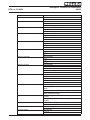
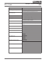
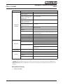
Service function
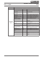
Component
activation
Component / Sensor tested
Component activation
Function tested/Machine response
Water path control unit M 24
position 1 and Y14
Water intake via door glass for 10 s
Water path control unit M 24
position 2, solenoid valve Y14,
heating R1 + R2, analog
pressure sensor
Water intake via compartment I, until level I is reached.
Heating to 35°C then begins.
Water path control unit M 24
position 3, solenoid valve Y14,
analog pressure sensor
Water intake via compartment II, until level II is reached
Water path control unit M 24
position 4, solenoid valve Y14,
analog pressure sensor
Water intake via compartment III (fabric conditioner), until level
III is reached
Drain pump M8 / Drain valve
Y26
Drain pump M8 activated / Drain valve Y26 opened. Drainage
without level control.
Wash agitation, drum drive
motor M5
Drum rotation with reversing action
Spin drive, drum drive motor M5
Drain pump M8 activated / Drain valve Y26 opened, drum drive
motor M5 activated. Drainage and spinning depending on spin
speed selector setting.
Hot water valve Y12
Water intake via compartment II, until level III is reached
Drum lighting H3/6
Drum lighting on
Alternative water supply valve
Y6
Water intake via compartment II, until level III is reached
Dispensing relay 1M9
Dispenser relay activation
Dispensing relay 2M9
Dispenser relay activation
Dispensing relay 3M9
Dispenser relay activation
Dispensing relay 4M9
Dispenser relay activation
Programme end signal
Mains voltage applied to pin 7 of payment system socket (X1/1)
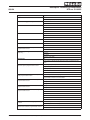
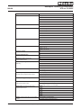
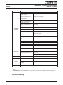
Sensor
State
Door contact (A2)
Door closed => Switch closed
Door open => Switch open
Sensor test
Payment system contact,
payment system socket (X1/1)
Connection wire bridge fitted between 1W14 pin 2/4 and
2W/14 pin 3/5
Connection wire bridge not fitted between 1W14 pin 2/4 and
2W/14 pin 3/5
Operating hours
counter display
Controls
Calibration
Power-programme module (ELP) Operating hours display
Buttons
Display indication for activated buttons
Display / LED test
All display points flash at the same time
Display background light
(backlight)
The backlight flashes on and off
Selection module (EW) test
See display for test results
Calibration not required as the machine does not have a load sensor
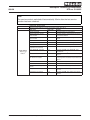
Table 3: Service mode summary
1)
If several faults are registered, their codes are shown one after the other in ascending order when the Start button is
pressed.
2)
Fault code deletion: Press the Start button for longer than 5 s during the fault code display (all stored fault codes are
deleted).
Quit (without saving)
A Open the door.
This information should not be duplicated or passed on without Miele approval. All rights reserved.
15.06.2005, DE_en