1
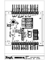
A INSTALLATION, OPERATION AND MAINTENANCE MANUAL FOR SH / S-TRAC GAS FIRED HUMIDIFER AND CONTROLLER INDOOR AND OUTDOOR MODELS UNIT MODEL NO. _________________ UNIT SERIAL NO. _________________ SERVICED BY: ___________________ TEL. NO: ________________________ CANADIAN HEAD OFFICE AND FACTORY USA HEAD OFFICE AND FACTORY 1401 HASTINGS CRES. SE CALGARY, ALBERTA T2G 4C8 Ph: (403) 287-4774 Fx: 888-364-2727 32050 W. 83 STREET DESOTO, KANSAS 66018 Ph: (913) 583-3181 Fx: (913) 583-1406 rd CANADIAN EASTERN FACTORY 1175 TWINNEY DRIVE NEWMARKET, ONTARIO L3Y 5V7 Ph: (905) 898-1114 Fx: (905) 898-7244 SALES OFFICES ACROSS CANADA AND USA Retain instructions with unit and maintain in a legible condition. Please give model number and serial number when contacting factory for information and/or parts. www.engineeredair.com Feb 06 A SH / S-TRAC MANUAL TABLE OF CONTENTS S-TRAC TERMINAL DRAWING .................................................................................................................. 2 YOU HAVE RESPONSIBILITIES TOO........................................................................................................ 5 INTRODUCTION ......................................................................................................................................... 5 SAFETY PRECAUTIONS............................................................................................................................ 5 WARRANTY................................................................................................................................................ 6 PARTS ........................................................................................................................................................ 6 RECEIVING................................................................................................................................................. 7 TEMPORARY STORAGE ........................................................................................................................... 7 INSTALLATION ........................................................................................................................................... 7 CODES ....................................................................................................................................................... 8 LIFTING ...................................................................................................................................................... 9 MOUNTING................................................................................................................................................. 9 SHIPPING MATERIALS ............................................................................................................................ 10 ASSEMBLY ............................................................................................................................................... 10 PIPING, ELECTRICAL OR CONTROL SERVICE CONNECTIONS .......................................................... 11 ELECTRICAL INSTALLATION .................................................................................................................. 11 Recommended 24V Field Wiring Size:................................................................................................ 12 NATURAL GAS INSTALLATION: .............................................................................................................. 13 GAS LINE TESTING (EXTERNAL TO THE UNIT) .................................................................................... 13 VENTING PRODUCTS OF COMBUSTION............................................................................................... 13 HUMIDIFIER INSTALLATION ................................................................................................................... 14 Supply Water...................................................................................................................................... 14 Outdoor installations........................................................................................................................... 14 Freeze Protection ............................................................................................................................... 15 Drain Connection................................................................................................................................ 15 Steam Line ......................................................................................................................................... 15 Condensate Line ................................................................................................................................ 15 SORB DISTRIBUTION GRID INSTALLATION .......................................................................................... 16 Absorption Distance............................................................................................................................ 16 Grid Orientation .................................................................................................................................. 16 Duct Installations ................................................................................................................................ 16 Duct Mounted controls........................................................................................................................ 16 OPERATION ............................................................................................................................................. 17 GENERAL OVERVIEW ............................................................................................................................. 17 Sequence of Operation....................................................................................................................... 18 Burner Control .................................................................................................................................... 18 SPECIFIC CONTROL FUNCTION EXPLANATIONS ................................................................................ 18 Probe safety checks ........................................................................................................................... 18 Probe sensitivity adjustment ............................................................................................................... 19 Fill valve operation.............................................................................................................................. 19 Tank fill cycle...................................................................................................................................... 19 Tank dump cycle ................................................................................................................................ 19 Tank warm-up..................................................................................................................................... 19 Dump mixing valve ............................................................................................................................. 20 Tank High Limit................................................................................................................................... 20 Overflow Protection ............................................................................................................................ 20 HUMIDITY CONTROL FUNCTIONS ......................................................................................................... 20 Humidity setpoint ................................................................................................................................ 20 Ambient reset ..................................................................................................................................... 21 Duct Mounted High Humidity limit ....................................................................................................... 21 3 of 29 Feb 06 A SH / S-TRAC MANUAL BURNER CONTROLS............................................................................................................................... 21 Flame Failure...................................................................................................................................... 21 DJM2 burner control (SH series 120, 240, 400, and 650) ................................................................... 21 Direct modulating gas output (SH series 35, 60, and 90) .................................................................... 21 STATUS AND ALARM FUNCTIONS ......................................................................................................... 22 TROUBLE SHOOTING.............................................................................................................................. 22 Service pot ......................................................................................................................................... 22 Flue Switch......................................................................................................................................... 22 Probe failure ....................................................................................................................................... 22 Water valve failure.............................................................................................................................. 23 MAINTENANCE ........................................................................................................................................ 23 SCALE REMOVAL .................................................................................................................................... 23 SAFETY SHUTOFF VALVE LEAK TEST: ................................................................................................. 23 GAS MANIFOLD ....................................................................................................................................... 24 OPERATIONAL CHECK FOR ALL GAS FIRED SH HUMIDIFIERS .......................................................... 24 Top Loading ....................................................................................................................................... 25 ELECTRODE DETAIL ............................................................................................................................... 26 UNIT SHUT-DOWN INSTRUCTIONS ....................................................................................................... 26 Service Shut Down ............................................................................................................................. 26 Emergency Shut Down ....................................................................................................................... 26 Start-Up After Extended Shut-Down Period ........................................................................................ 26 GAS MANIFOLD ....................................................................................................................................... 27 BURNERS................................................................................................................................................. 27 START-UP RECORD ................................................................................................................................ 28 © Airtex Manufacturing Partnership. All rights reserved. 4 of 29 Feb 06 A SH / S-TRAC MANUAL YOU HAVE RESPONSIBILITIES TOO This installation, operation and maintenance manual can not cover every possibility, situation or eventuality. Regular service, cleaning and maintaining the equipment is necessary. If you are not capable of performing these tasks, hire a qualified service specialist. Failure to perform these duties can cause property damage and/or harm to the building occupants and will void the manufacturers’ warranty. Warning: m Improper installation, adjustment, alteration, service or maintenance can cause property damage, injury or death. Read the installation, operating and maintenance instructions thoroughly before installing or servicing this equipment. INTRODUCTION Engineered Air units are high quality products designed and manufactured to provide many years of trouble-free operation. We recommend that this manual be read thoroughly to ensure proper installation, efficient operation and proper maintenance of this equipment. The submittal record is considered to be part of the Installation, Operation and Maintenance Manual. SAFETY PRECAUTIONS Read, understand and follow the complete manual before beginning the installation, including all safety precautions and warnings. Warning! mhg If the information in this manual is not followed exactly, a fire or explosion may result causing property damage, personal injury or loss of life. - Do not store or use gasoline or other flammable vapors and liquids in the vicinity of this or any other appliance. - WHAT TO DO IF YOU SMELL GAS Do not try to light any appliance. Do not touch any electrical switch; do not use any phone in your building. Immediately call your gas supplier from a neighbor’s phone. Follow the gas supplier’s instructions. If you cannot reach your gas supplier, call the fire department. - Installation and service must be performed by a qualified installer, service agency or the gas supplier. mhg FOR YOUR SAFETY The use and storage of gasoline or other flammable vapours and liquids in open containers in the vicinity of this appliance is hazardous. mhg FOR YOUR SAFETY If you smell gas: 1. Open windows. 2. Do not touch electrical switches. 3. Extinguish any open flame. 4. Immediately call your gas supplier 5 of 29 Feb 06 A Warning: m c SH / S-TRAC MANUAL This unit is connected to high voltages. Electrical shock or death could occur if instructions are not followed. This equipment contains moving parts that can start unexpectedly. Injury or death could occur if instructions are not followed. All work should be performed by a qualified technician. Always disconnect and lock out power before servicing. DO NOT bypass any interlock or safety switches under any circumstances. WARRANTY ENGINEERED AIR will furnish without charge, F.O.B. factory, freight collect, replacement parts for, or repairs to parts covered herein which prove defective in material or workmanship under normal and proper use within one year from the date of delivery, provided the customer gives ENGINEERED AIR written notice of such defects and provided that inspection by ENGINEERED AIR establishes the validity of the claim and all pertinent invoices have been paid in full. The correction of such defects or replacement will be made only when the complete product or part(s) claimed defective are returned to ENGINEERED AIR, transportation charges prepaid, if such return is requested by ENGINEERED AIR. Repairs or replacements as provided by the foregoing paragraph shall constitute fulfillment of all ENGINEERED AIR’s obligations with respect to this warranty. The refrigerant charge is not included in any part of this warranty. ENGINEERED AIR shall not be liable for any damage to person, property, loss of revenue, or expense incurred, irrespective of cause. This warranty does not apply to any products or parts thereof that have been subject to accident, misuse or unauthorized alterations, or where ENGINEERED AIR’s installation and service requirements have not been met. The foregoing warranty is in lieu of all other warranties, expressed or implied. ENGINEERED AIR Warranty is void if: 1. 2. 3. 4. 5. The unit is not installed in accordance with this manual. The start-up and operation of the unit is not performed in accordance with this manual. The unit is operated in an atmosphere containing corrosive substances. The unit is allowed to operate during building construction. The unit is allowed to operate in atmospheres where chlorine or chlorine compounds are present or which contain any contaminant (silicone, aluminum oxide etc.) that adheres to the spark ignition flame sensing probe. PARTS 1. Motors: Motor manufacturers have service centers that will repair or replace motors as required. 2. Parts Other Than Motors: Contact the nearest Engineered Air sales office or factory. Be sure to include Model Number, Serial Number, date of installation and nature of failure along with the description of the parts required. Some parts may not be stocked items that must be made or ordered. 6 of 29 Feb 06 A SH / S-TRAC MANUAL RECEIVING Refer to the back of the packing slip for receiving unit instructions. On receipt of the unit, check for damage. Inspect protective covers for punctures or other signs that there may be internal damage. Remove protective covers and check for internal damage. Replace covers if the unit is not being assembled or installed at this time. Open access doors and check for internal damage. Close access doors when the inspection is complete All units are pre-tested at the factory immediately prior to shipping and are ensured to be in good operating condition at that time. If damage is found follow the instructions on the packing slip. On receipt of the unit, check electrical characteristics (see rating plate) to make sure the unit voltage is compatible with that available for the unit. All parts for field installation are listed on the shipping order form. TEMPORARY STORAGE If a unit is to be stored prior to installation the following precautions are required: • • • • • Store in a well drained area that will not accumulate surface water. Store in an area where the unit will not get damaged. The entire perimeter and any full height cross members of the unit must be supported by a level surface and the supporting surface must be adequate for supporting the entire weight of the unit. All protective coverings that were provided for shipping must be in place. Protect indoor units from rain and snow. INSTALLATION Warning: mg Caution: m This unit is not explosion proof and cannot be installed in areas requiring any explosion proof rating. All wiring, piping and fuel line installation must be completed by qualified persons in accordance with all federal, state, provincial and/or local codes. Note: Installation shall be in accordance with this manual and all other associated component and control Installation, Operation and Maintenance Manuals. 7 of 29 Feb 06 A SH / S-TRAC MANUAL CODES In Canada: 1. The installation of this unit shall be in accordance with the latest edition of the Canadian Electrical Code, Part 1 – C.S.A. Standard C22.1, Provincial and Local Codes, and in accordance with the local authorities having jurisdiction. 2. This unit shall be electrically grounded in accordance with the latest edition of the Canadian Electrical Code, Part 1 – C.S.A. Standard C22.1, Provincial and Local Codes, and in accordance with the local authorities having jurisdiction. 3. The installation of this unit shall be in accordance with the latest edition of the Canadian Natural Gas and Propane Installation Code, C.S.A. Standard B149.1, Provincial and Local Codes, and in accordance with the local authorities having jurisdiction. 4. The installation of this unit shall be in accordance with the latest edition of the National Plumbing Code of Canada, Provincial and Local Codes, and in accordance with the local authorities having jurisdiction. 5. The installation of this unit shall be in accordance with all other National, Provincial and Local Codes, and in accordance with the local authorities having jurisdiction. In USA: 1. The installation of this unit shall be in accordance with the latest edition of the National Electrical Code (ANSI/NFPA 70), State and Local Codes and in accordance with the local authorities having jurisdiction. 2. This unit shall be electrically grounded in accordance with the latest edition of the National Electrical Code (ANSI/NFPA 70), State and Local Codes and in accordance with the local authorities having jurisdiction. 3. If the unit has not been provided with an electric disconnect switch, one of adequate ampacity shall be installed in accordance with Article 430 of the National Electrical Code (ANSI/NFPA 70). 4. The installation of this unit shall be in accordance with the latest edition of the National Fuel Gas Code ANSI/Z223.1/NFPA 54, State and Local Codes and in accordance with the local authorities having jurisdiction. 5. The installation of this unit shall be in accordance with the latest edition of the National Standard Plumbing Code (NSPC), State and Local Codes and in accordance with the local authorities having jurisdiction. 6. The installation of this unit shall be in accordance with all other National, State and Local Codes, and in accordance with the local authorities having jurisdiction. 8 of 29 Feb 06 A SH / S-TRAC MANUAL MINIMUM CLEARANCE FOR SERVICE AND TO COMBUSTIBLES IN INCHES (mm) COMBUSTIBLE CLEARANCE SERVICE CLEARANCE TOP FRONT BACK SIDE BOTTOM* FLUE OPPOSITE BURNER SIDE 24" (610) 6" (152) 6" (152) 6" (152) 0 9" (229) NA MODEL SH SERVICE/ BURNER SIDE CONTROL PANEL 24" (610) 42" (1067) * 6” (152) clearance from bottom of the tank compartment. For Safety and Service, the minimum clearances must be observed. Minimum clearances also provide adequate combustion air supply. LIFTING When shipped for field installation, the SH is shipped on a skid. The SH humidifier will be packed inside a shipping crate suitable for moving with a fork truck. Place the humidifier at its desired location, and then remove the crating and shipping material. Stand alone or packaged outdoor installations will have the SH humidifier mounted inside a weather tight enclosure, designed for curb mounting. The enclosure is constructed on a structural steel base frame. The unit base frame is equipped with lifting lugs specifically located to facilitate proper lifting of the unit. Spreader bars must be used to keep rigging away from the unit cabinetry. All lifting lugs must be used. If using a lift truck, ONLY lift using the perimeter structural frame. DO NOT allow forks to lift on cabinet or unit floor. Note: There may be bottom mounted components, such as drain piping , that can be easily damaged. Warning: m Injury or death can result from improper rigging and lifting. Rigging and lifting of equipment must be performed by qualified personnel with proper equipment using appropriate and approved safety precautions. MOUNTING Units must be mounted level. Failure to do so can cause water to be trapped in drain pans or operational problems that can void warranty. Failure to do so can result in injury or death, damage the equipment and/or building and can be a cause of poor indoor air quality. Equipment must be installed so that sufficient working clearance and component access is provided. Base mounting – Unless the unit is specifically designed for point mounting, the base of the unit must be supported continuously by a mounting support system that is directly below the unit structural base frame and runs the entire length and width of the unit. Roof curb mounting – The curbs are constructed of heavy gauge load bearing, galvanized steel, and must be fully insulated after installation. Wood nailer strips are provided for easy attachment of roof flashing. Gasket material is supplied with the unit and must be field mounted on the curb to seal the joint between the curb and the unit frame. The curb must be supported along its entire perimeter and any full height cross members as shown on the shop drawings. Point loading of curbs is not permissible. 9 of 29 Feb 06 A SH / S-TRAC MANUAL The gasket material provided for the curb is closed cell foam. Closed cell foam is dense and does not compress easily. If the unit is split and shipped in sections there will also be gasket material for sealing between sections. The gasket material for splits is open cell foam. It is less dense than the closed cell foam and compresses easily. ONLY USE THE CLOSED CELL FOAM GASKET PROVIDED FOR SEALING THE CURB. Curbs may be broken down for shipping. Field assembly is required by the installing contractor. Bolt all sections together at split joints using hardware provided. The installing contractor must caulk and seal all joint and corner flashings. All flashings and braces that are provided must be installed. DO NOT screw/penetrate joint, corner or adaptor flashings. Refer to assembly instructions sent with roof curb. Outdoor installation (inside a packaged air handler or Engineered Air enclosure) – Outdoor installation enclosures will typically have a pipe chase installed in the enclosure floor for the natural gas, drain and water connections. Use all connections provided. Refer to the installation and mounting instructions included with the main equipment. SHIPPING MATERIALS Remove shipping materials. Shipping materials may include, but are not limited to: • Protective covers over openings, inlets, condenser coils etc. • Protective covers over split sections if provided. • Tie-down bolts, straps and blocks on fan and compressor vibration isolators. • Tie-down bolts, straps and blocks on tilt equipped heat pipes and enthalpy/desiccant wheels if supplied. • Indirect fired heat exchangers may be supported with wood for shipping. Remove. ASSEMBLY Warning: m Assembly of split units requires bolting together the base frame of adjacent sections. This may require personnel to work under the unit during assembly. Injury or death can result from improper support or improper loading of the curb. Additional temporary support shall be provided by the installer for the safety of personnel. If the unit is split and shipped in sections, the sections must be field assembled. All sections are pre-drilled for assembly. The hardware and gaskets are packed in one of the sections. Apply the gasket, align the sections. The base frame must be bolted together first. Access below the unit for bolting of the base frame must be provided. Once the base frame has been tightly fastened, loosely assemble all the bolts and nuts, and then tighten. Caulk all split lines. Install split joint caps. The inlet hood is designed for field installation. On outdoor units connect the hood to the support flange and attach with appropriate fasteners. Connect all wiring on units that had been split for shipment. The gasket material provided for the split is open cell foam. Open cell foam is light and compresses easily. If the unit is mounted on a curb provided by Engineered Air there will also be gasket material for sealing the curb. The gasket material for curbs is closed cell foam. It is more dense than open cell foam and does not compress as easily. ONLY USE THE OPEN CELL FOAM GASKET PROVIDED FOR SEALING THE SPLIT(S). 10 of 29 Feb 06 A SH / S-TRAC MANUAL PIPING, ELECTRICAL OR CONTROL SERVICE CONNECTIONS DO NOT install anything that will interfere with equipment access or the rating plate. Engineered Air equipment is constructed with cabinet and floors designed to prevent water from entering the building through the installed unit. When ordered, factory installed pipe chases and/or electrical chases are built into the unit floor. Factory chases are provided with covers that need to be replaced and sealed after piping and electrical connections are made. THE FLOOR OF THE UNIT HAS BEEN MADE WATER-RESISTANT. DO NOT CUT OR DRILL HOLES IN THE FLOOR OR USE PENETRATING FASTENERS. All penetrations through the unit walls must be caulked and sealed to prevent air and/or water from entering the unit. ELECTRICAL INSTALLATION DO NOT install anything that will interfere with equipment access or the rating plate. The unit must be electrically grounded and all wiring must be installed in accordance with the National Electrical Code, ANSI/NFPA 70, and/or the Canadian Electric Code CSA 22-1 and to the approval of the authorities having jurisdiction. THE FLOOR OF THE UNIT HAS BEEN MADE WATER-RESISTANT. DO NOT CUT OR DRILL HOLES IN THE FLOOR OR USE PENETRATING FASTENERS. Field wiring diagrams, internal wiring diagrams and operating functions are included in the control cabinet. The power requirements are indicated on the rating plate. Where field wiring of control circuits is required, take care to size the field wiring for a maximum 10% voltage drop. The control circuit ampacity is noted on the field wiring diagram. See the field wiring diagram for requirements for shielded or twisted pair wire for solid state devices. Warning: m No unspecified external load shall be added to the control transformer circuit(s) or to the main power circuit(s). 11 of 29 Feb 06 A SH / S-TRAC MANUAL Recommended 24V Field Wiring Size: Copper conductors only Circuit Load (Amps) (1) Maximum Total Length of Run < 50 Ft < 100 Ft < 150 Ft < 200 Ft < 250 Ft < 300 Ft < 350 Ft < 400 Ft < 450 Ft < 500 Ft (~ 15 m) (~ 30 m) (~ 45 m) (~ 60 m) (~ 75 m) (~ 90 m) (~ 105 m) (~ 120 m) (~ 135 m) (~ 150 m) 1 16 AWG 16 AWG 16 AWG 16 AWG 16 AWG 16 AWG 14 AWG 14 AWG 14 AWG 12 AWG 2 16 AWG 16 AWG 16 AWG 14 AWG 12 AWG 12 AWG 12 AWG 10 AWG 10 AWG 10 AWG 3 16 AWG 16 AWG 14 AWG 12 AWG 12 AWG 10 AWG 10 AWG 10 AWG 4 16 AWG 14 AWG 12 AWG 10 AWG 10 AWG 10 AWG 5 16 AWG 12 AWG 12 AWG 10 AWG 6 16 AWG 12 AWG 10 AWG 10 AWG 7 14 AWG 12 AWG 10 AWG 8 14 AWG 10 AWG 10 AWG 9 14 AWG 10 AWG 10 12 AWG 10 AWG 11 12 AWG 10 AWG 12 12 AWG 10 AWG 13 12 AWG 14 12 AWG 15 12 AWG Notes: 1) The field wiring load depends on the actual load on a particular control circuit the field wiring is connected to. Refer to the internal wiring diagram of the unit. 2) The table above is based on a maximum 10% voltage drop on a 24V control circuit. Wire size was calculated using the following formula: CM = (25 x I x L ) / V Where CM is circular mils of conductor for a constant load of I amps, wire length L in feet from the unit to the field device and back, and voltage drop V. When connecting to a three phase power supply, check for the correct rotation of all motors and fans. If the rotation is incorrect, reverse the rotation at the incoming power only. All electrical conduit outlets in the control panel must be sealed to prevent moist building air from migrating to the control panel. All penetrations through the unit walls must be caulked and sealed to prevent air and/or water from entering the unit. 12 of 29 Feb 06 A SH / S-TRAC MANUAL NATURAL GAS INSTALLATION: 1. Installation must be made in accordance with the requirements of the authorities having jurisdiction. 2. Check the unit rating plate and confirm fuel type, supply pressure, input rating and temperature rise. 3. Gas supply pressure higher than the unit rating plate requires an additional field supplied gas regulator. 4. Install an approved appliance shutoff valve on the gas supply in accordance with the requirements of the authorities having jurisdiction. 5. Gas lines shall not interfere with unit access. The gas line connection at the heater shall have an approved drip leg with screwed cap. 6. A minimum 1/8 inch NPT plugged tapping, accessible for test gauge connection, must be installed immediately upstream of the gas supply connection to the unit. 7. On indoor units any control device (regulator, diaphragm valve, high and low pressure switch, etc.) that requires a bleed or vent line, must be vented in accordance with applicable codes. GAS LINE TESTING (EXTERNAL TO THE UNIT) The appliance and its individual shutoff valve must be disconnected from the gas supply piping system during any testing of that system at test pressures in excess of 0.5 psi (3.5 kPa). The appliance must be isolated from the gas supply system by closing its individual shutoff valve during any testing of that system at test pressure equal to or less than 0.5 psi (3.5 kPa). VENTING PRODUCTS OF COMBUSTION Installation shall be in accordance with the requirements of authorities having jurisdiction and ANSI Z2231/NFPA 54 or CSA B149.1. Heaters must be provided with sufficient combustion air and shall not be located in an area where a negative pressure will be created that will starve the burner of combustion air. Flue outlet pressure must not exceed maximum over fire pressure shown on the nameplate. CHIMNEY TYPE "B" OR EQUIVALENT COMBUSTABLE AS REQUIRED BY INSTALLATION CODE / AUTHORITY VENT CONNECTOR Do not connect the vent to any portion of mechanical draft systems that are under positive pressure. Do not install dampers or other restrictive devices in the flue vent pipe. DRAFT HOOD INDOOR UNIT Vent terminations shall be in accordance with the requirements of the authorities having jurisdiction. BURNER The vent shall be installed in such a manner that access to the appliance or unit rating plate is not obstructed. 13 of 29 Feb 06 A SH / S-TRAC MANUAL Indoor 1. A vertical chimney must be certified “A” or “L” or equivalent type on units without draft hoods. Type “B” vent is acceptable on units with Engineered Air draft hoods. The vent size shall be selected from appropriate approved Vent Table. 2. A vent connector shall be of approved material and installation. It shall have a minimum clearance of 9" (229 mm) to combustible material. All horizontal portions of the venting system shall be supported to prevent sagging. All horizontal runs shall have a minimum rise of 2% in the direction of discharge. Horizontal vents shall be properly supported. 3. Units without draft hoods shall have individual chimneys. 4. This appliance shall not be connected to any portion of a mechanical draft system operating under positive pressure. 5. See separate Supplemental Installation Instructions for units that have side wall venting. Outdoor Where appropriate, Engineered Air outdoor vent terminations may be provided. Attach the vent termination securely to the unit casing using #8 X 5/8” (minimum) sheet metal screws with washers at all holes provided. When the chimney and flue cap are provided by others, install in accordance with the instructions for the chimney and flue cap and to the requirements of the authorities having jurisdiction. The chimney shall have a temperature rating equivalent to “A” vent and be suitable for outdoor installation. Support the chimney independent of the unit. HUMIDIFIER INSTALLATION Supply Water The supply water pressure range must be between 25 psi (172kPa) and 80 psi (551kPa). If using nonmetallic water piping, it must be rated to withstand 212°F (100°C). Do not use heated supply water. The supply water also mixes with the drain water to temper the leaving drain temperature. SH humidifiers may be ordered with 2 inlet water connections; one for boiling and one for drain mixing. Refer to the mechanical drawing to determine each connection. Engineered Air recommends installing a water hammer arrester. Always install a supply water manual shut off valve at the humidifier. Outdoor installations A piping and wiring chase is provided on outdoor applications. The installing contractor shall provide freeze protection for the supply water line on outdoor installations. A 3-way fill solenoid is recommended to be installed indoors to allow the supply water line to drain in the event of a power failure. 14 of 29 Feb 06 A SH / S-TRAC MANUAL Freeze Protection Outdoor equipment will normally be supplied with an electric heater installed in the humidifier section. A temperature control will energize the heater at 40°F (4°C). A low limit will disable the humidifier to initiate a drain cycle at 35°F (2°C) to help protect the humidifier from freezing damage. A dry contact, available to control a solenoid valve to drain the water supply line, will open as well. Drain Connection Drain water temperatures will normally be tempered by mixing supply water with the hot drain water to a leaving temperature between 120°F (49°C) and 140°F (60°C). In the event of a power failure, near boiling water could enter the drain line. If using nonmetallic drain piping, it must be rated to withstand 212°F (100°C). The drain line must not be trapped or valved and must gravity drain to an open indoor drain, with a 1” (25) air gap. Steam Line Do not use plastic material for the steam line. The steam line is hot and should be properly insulated to reduce heat loss and provide protection against personal injury. The steam line should not exceed 50ft (15.3m) equivalent. The steam line must be sloped at 2% grade back towards the humidifier and must not be trapped. For installations with a steam line greater than 50ft (15.3m) equivalent consult Engineered Air. Condensate Line Do not use plastic material for the condensate line. Where possible the SORB distribution grid condensate line should sloped at 2% grade back towards the humidifier. Refer to the grid installation drawing included in the submittal for trapping requirements. This stub is welded closed at the factory, but may be opened for connection as required. If the condensate line cannot be returned to the humidifier it must be piped to a drain. Multiple SORB distribution grids require multiple condensate lines. 15 of 29 Feb 06 A SH / S-TRAC MANUAL SORB DISTRIBUTION GRID INSTALLATION The distribution grid is built for specific duct dimensions and air flow. Do not install the grid into any other duct or system than it was designed for. The duct mounting location should be in a straight length of duct and shall not be near any transitions or elbows which could affect airflow across the grid. Do not install the grid near the outlet of a blower or locations with high velocities. Maximum operating duct static pressure is 2.5 “w.c. (620 Pa). Higher duct static pressures are possible, but must be indicated prior to ordering the humidifier and steam grid. Absorption Distance When steam first leaves the SORB distribution grid it is a hot invisible gas. As it travels into the air stream, the steam cools and condenses into fog. The fog then evaporates into the large volume of supply air. A very slight increase in duct air temperature will occur. The standard duct installation absorption distance is 36” (914), beginning 8” (203) upstream of the grid. Grid Orientation Refer to the SORB distribution grid drawing included with the submittal records. Duct Installations If the duct is insulated on the inside it must be encased within a solid duct liner, and incorporate a drain pan with a properly sized drain trap. The liner and drain pan must extend at least the length of the absorption distance. Refer to the SORB distribution grid installation drawing included in the submittal package. Duct mounted grids are equipped with stainless steel adjustable mounting brackets. Duct Mounted controls The humidity high limit must be mounted near the top of the duct, 3 – 10ft (1 – 3m) downstream from the distribution grid. This control is typically set between 80 and 85%RH. An air proving device is required on all applications, and is normally located at the supply fan feeding the duct and distribution grid. 16 of 29 Feb 06 A SH / S-TRAC MANUAL OPERATION Warning: m c Warning: m This unit is connected to high voltages. Electrical shock or death could occur if instructions are not followed. This equipment contains moving parts that can start unexpectedly. Injury or death could occur if instructions are not followed. All work should be performed by a qualified technician. Always disconnect and lock out power before servicing. DO NOT bypass any interlock or safety switches under any circumstances. Proper commissioning and start-up of the associated air handling system is the responsibility of the installing contractor. It is recommended that an air balance be completed by a certified air balancing contractor to insure the air volume being delivered matches the air handling system rating plate. The humidifier has been selected to perform with the design airflow and static pressure. Failure to perform a proper air balance can cause injury or death, damage to the equipment, property damage, system operational problems, or be a cause of poor air quality. Moisture carry over can result from improper air flow. GENERAL OVERVIEW The S-TRAC controller is designed to perform the majority of functions required to generate and control ‘dry’ steam humidification. Control options may include room or return duct humidity sensing, ambient temperature reset, and internal or external RH setpoint. A remote humidity setpoint signal (0-10Vdc = 0-100%RH) from a supervisory building management system (BMS) is also available. Direct control of the humidifier from a 0-10Vdc control signal is another option. Other intrinsic features include water level control, continuous drain temperature monitoring, automatic tank reload timing, variable water quality settings, adjustable window ‘R’ value ambient reset, and diagnostic/operation lights. The Engineered Air SH series of humidifiers reduce mineral build up by draining the entire volume of water in the tank once a day (typical). This is referred to as a ‘dump’ or ‘drain’ cycle. How often the cycle must be initiated, and how long the cycle takes to complete, is determined either by the S-TRAC internal run time monitor, an occupied time clock or from an interlock to the supply air equipment. An external air proving device and high humidity limit sensor must be used for all applications. Humidity control sensors must be located in areas or ducts that have negligible changes in temperature. As relative humidity is based on the sensible temperature of the air the humidity control sensor must be installed in the return air duct or in the supplied space. Do not install humidity control sensors in the supply air duct. Humidifiers mounted in locations susceptible to low temperatures must have special attention paid to keeping the humidifier and water lines safe from freezing. An additional heat source should be installed in the humidifier location as well as heat tracing and insulation on the supply water piping. A low temperature condition will cause the S-TRAC to initiate a complete drain. A remote mounted 3-way self-draining fill valve is recommended to gravity drain water in the supply line in the event of a power failure. 17 of 29 Feb 06 A SH / S-TRAC MANUAL Sequence of Operation When terminal H is powered and the time clock (or external enable) contact closes and powers terminal HS, the S-TRAC will close the drain valve and enable the fill solenoid to commence filling the tank with water. When the water level has reached the low level sensor/switch the gas fired burner is enabled if a call for humidity is present. The fill valve will stay energized until the water level reaches the high level sensor/switch. The burner will bring the water to boiling then modulate the firing rate to control the steam output to maintain the required relative humidity. The steam is then piped to the Engineered Air SORB distribution grid mounted in the air-stream. The amount of steam produced will decrease as the burner firing rate lowers from a reduced call for humidity. Water level will be automatically maintained between the low and high level probes. If the call for humidity is satisfied and the burner is operating at low fire, it will shut down and wait. Steam output may be reduced as the tank during re-fill. When the time clock (or external enable) contact opens, or the internal run time monitor expires, the S-TRAC will initiate the dump cycle. The burner is disabled and the drain valve opens. A sensor located in the drain line constantly monitors drain temperature. If the drain temperature exceeds 120°F (49°C) the mixing solenoid is enabled to add cool water to the drain. If the drain temperature reaches 140°F (60°C) the drain valve will be disabled and begin to close to restrict the amount of hot water leaving the humidifier, increasing the percentage of cool mixing water going to the drain. Burner Control The S-TRAC will directly control burner operation on the small sizes of SH humidifiers (SH-35,60,90). These use hot surface ignition, constant combustion air, with 3:1 turndown. The burner and ignition control are directly signalled from the S-TRAC. Refer to the burner set-up section of this manual. The S-TRAC controller on large sizes of SH humidifiers (SH-120,240,400,650) interface to an Engineered Air DJM high turndown burner controller. These style of 15:1 turndown burners have spark to pilot ignition and modulating combustion air. Refer to the DJM manual included with the SH humidifier for burner information and set-up procedures. SPECIFIC CONTROL FUNCTION EXPLANATIONS Probe safety checks The S-TRAC constantly monitors the activity of the 2 level sensors/switches. If any discrepancies in the sequence of level sensing occur, the S-TRAC will lockout on probe problem. For example, if the high level sensor/switch makes before the low level sensor/switch. 18 of 29 Feb 06 A SH / S-TRAC MANUAL Probe sensitivity adjustment For level sensor conductivity purposes, the S-TRAC has 4 face-mounted water quality jumper clips that are factory set based on the required water quality tests. Water Hardness (ppm) Internal dump timer (hours at full fire) Jumper #1 Jumper #2 Jumper #3 Jumper #4 30 20 15 10 Closed Closed Open Open Closed Open Closed Open Open Closed Closed Closed Open Closed Closed Closed Very soft (<30) Soft (30-60) Moderate (60-120) Hard (>120) Fill valve operation The tank water surface is quite turbulent when it is boiling. Before the fill water valve is energized, the fill probe must not be sensing water for a few seconds. Once the fill water valve is opened, it will remain open until the fill probe has been covered for a period of time. This time value is set by dip switch #2. SH size Dip switch #2 Coverage time (seconds) 240 and smaller Open 8 400 and larger Closed 16 Tank fill cycle The time it takes to fill the SH humidifier is also monitored. If the valve stays open for too long, without covering the fill probe, the S-TRAC will assume there is a fault with the supply water line, and close the fill valve and lock out. Tank dump cycle Interrupting power to the HS terminal will always initiate a full dump cycle. If the HS contact is not cycled (continuous operation) an internal run timer will also initiate a dump cycle. There is no steam production during a dump cycle. The dump cycle is a timed event, and if the water level does not fall below the low water probe by the end of that time, the S-TRAC will lock out. The time of the dump cycle is also set by dip switch #2. If the humidifier is operating below full fire the internal dump timer value is recalculated and will automatically reset the timer up to a maximum of twice the hour value indicated in the above table. The drain valve on outdoor installations is spring return, normally open valve to prevent freezing on power failure. Disconnecting the power to the humidifier will open the drain valve. When unpowered the S-TRAC cannot control the drain temperature mixing valve. Indoor mounted humidifier drain valves are not spring return. Tank warm-up After each dump or refill cycle the burner is brought to maximum fire to quickly heat the fresh water to boiling temperature, regardless of the humidity requirements. The burner is then allowed to modulate to provide the correct amount of steam required. 19 of 29 Feb 06 A SH / S-TRAC MANUAL Dump mixing valve During each dump cycle a mixing valve is energised to add cool water to the drain, as the hot tank water is drained, to reduce the leaving water temperature. As supply water pressure and temperature varies from location to location, the amount of water the mixing valve can supply to the drain will also vary. If the mixing water volume is too low, or the mixing water temperature is too high, the resulting drain water temperature will be too high. To overcome this several things may have to be done. 1. Increase the supply water pressure. 2. Increase the size of the mixing water valve. 3. Reduce the tank drain valve flow rate. Note: If the drain valve flow rate is reduced too much, the velocity of the water may not be enough to flush the system of residual minerals. Tank High Limit This limit will protect the heat exchanger from firing in the event of a ‘dry’ tank. Set at 400°F (200°C), this sensor will disable the heating until manually reset. It is located on the heat exchanger primary drum at approximately the 10:00 or 2:00 o’clock position. Overflow Protection When the S-TRAC and humidifier are operating normally (not in a dump cycle) the drain temperature will always be cool. If the drain temperature becomes hot this is an indication that the tank has overflowed either with water or steam (leaking drain or fill valve, plugged or kinked steam line, water level too high). All of these conditions will cause the S-TRAC to lock out on tank overflow. HUMIDITY CONTROL FUNCTIONS Humidity setpoint The S-TRAC has two different methods to set the desired room humidity set point (requested set point). The setpoint source can either the face mounted setpoint dial or from an external 0-10Vdc source (10V=100%RH). The actual setpoint may not match the requested setpoint. As an option the S-TRAC will override the requested setpoint when external conditions such as low outside ambient temperatures or duct humidity levels approaching 80% (modulating high humidity limit). The requested humidity setpoint and the actual setpoint can be measured using the two test points marked REQUESTED RH SP and OPERATING RH SP using a DC voltmeter from the test points to ground (1V=10%RH). If a BMS 0-10Vdc input is used to directly modulate the S-TRAC burner output, note that the actual S-TRAC response range is 2 - 8Vdc. The burner will be at high fire above 8Vdc. No external resets are activated when the S-TRAC is under direct control. Control Dip switch #3 Dip switch #4 Stand Alone off off Remote on off Direct off on 20 of 29 Feb 06 A SH / S-TRAC MANUAL Ambient reset This option is activated by installing an Engineered Air TE6000 ambient air sensor to terminals AMB and U. As the ambient temperature falls, the building outside walls and glass will cool down. Once the inside surface temperature falls below the dew point temperature, condensate will begin to form. To prevent moisture build-up the S-TRAC will automatically reduce the humidity setpoint. If the ambient sensor is to be field installed care must be take to ensure the sensing location is not affected by external loads, such as sunlight. Setting the S-TRAC to an appropriate value with the window ‘R’ value pot can modify the amount of ambient reset further. The pot on the face of the S-TRAC is labelled low, medium and high. If window fogging continues to occur turn the potentiometer slightly towards the lower setting. Duct Mounted High Humidity limit Modulating or snap acting high humidity sensors are wired into RH-D and Z (+ to RH-D and - to Z). If the supply air volume is too low or too cold it may be possible for condensate to form inside the supply duct. To prevent this a modulating duct RH limit will reduce the S-TRAC RH setpoint automatically as the duct humidity level approaches 80% (fixed) or disable the humidifier entirely using a make/break high humidity limit set at 85% (also installed across RH-D and Z). Warning: m Duct humidity high limits (either modulating or snap acting) and air flow proving are required on all systems. BURNER CONTROLS Flame Failure After closing the ENH (enable burner) output contacts, the S-TRAC must see proof of flame from a main valve feedback wire into terminal VFB24 (24Vac) within a pre-set amount of time, or it will cause a flame failure alarm. If the S-TRAC sees a signal indicating the main gas valve is energized when it does not have the ENH contacts closed, it will also cause a flame failure alarm condition. The S-TRAC will enable the dump cycle on flame failure. DJM2 burner control (SH series 120, 240, 400, and 650) The S-TRAC cannot directly control high turndown burner modulation. It can, however, provide a 2-10Vdc output signal to an Engineered Air DJM2 (high turndown modulating burner controller). In this application the DJM2 and its flame relay will control all the burner functions. The DJM2 must be set for full proportional control and cycle off only when the input voltage from the S-TRAC is below 2Vdc. Consult the DJM2 manual. Direct modulating gas output (SH series 35, 60, and 90) The S-TRAC can control most basic burner functions when modulating combustion air is not required. It provides low fire light off and can directly control a modulating gas flow ratio valve. 21 of 29 Feb 06 A SH / S-TRAC MANUAL STATUS AND ALARM FUNCTIONS The S-TRAC has 2 LED lights which are used for both status and failure annunciation. The type of flash and the colour of the LED convey the information. Flash Style Constant on Slow flash (2 sec on) Fast flash (½ sec on) Green LED Normal cycle Dump cycle Start Flame Very fast (1/8 sec on) Irregular (2 sec on, ½ sec on) Blip Power up test Start up problem Terminal EN not powered or no call for humidity Red LED Tank filling Drain problem detected Flame failure, Tank high limit, or Gas valve problem Probe problem Tank overflow Tank not filling in time Note: Whenever the S-TRAC detects a problem it will close the contact between AL1 and AL2. TROUBLE SHOOTING Service pot Turning on Dip switch #1 enables service mode. This allows for a qualified service technician to manually adjust the firing rate using the service pot. This is primarily used for combustion set-up. Warning: m Never leave the SH humidifier in service mode as all external humidity sensing is bypassed. Flue Switch Indoor SH Humidifiers may be equipped with a draft hood. If flue gases are being back drafted, a temperature sensing switch mounted at the base of the draft hood that will open and disable the heating. Under normal conditions the flue switch will be kept cool by being washed over by room temperatures that enter at the base of the flue. The flue switch temperature setpoint is 180°F (80°C). Probe failure Probes can develop internal shorts or external insulator bridging. When this occurs the probes will always show as having conductivity. To verify their operation the S-TRAC checks the conductivity of the probes before starting. Both probes must show open resistance to ground. During the fill cycle the low and fill probes must also prove continuity in the correct sequence. Failure to do so will result in lockout. The low fill probe tip must be located ½” (13 mm) higher than the top of the heat exchanger primary drum. The High fill probe tip must be located 1 ¼” (32 mm) above the low fill probe tip. Contact Engineered Air for replacement probes. 22 of 29 Feb 06 A SH / S-TRAC MANUAL Water valve failure The S-TRAC has internal timers to monitor the valve activity. When a valve or fill rate do not behave in a logical manner a lock out will occur. For example, if the S-TRAC started to refill the tank water level, but after several minutes the water level still has not proved conductivity on the fill probe (no water, failed valve) the S-TRAC will lockout. This is a pre-set timed event based on the size of the humidifier. MAINTENANCE SCALE REMOVAL Over time calcium and other minerals will build up on the water probes, tank and heat exchanger. As the calcium builds up the probe resistance will increase. The water level has to rise to a higher level before conductivity is proven. Given enough time and lack of maintenance the water level will keep rising until it overflows. At this point the S-TRAC will lock out. To restore operation, the probes must be cleaned or replaced. The type of steel used in the tank and heat exchanger has a relatively high coefficient of expansion. As the tank heats and cools, the built up scale will crack and eventually fall off. To clean, open the tank lids, and remove any fallen scale from the bottom of the tank and then use a moisture rated vacuum to remove the remaining smaller pieces. Ensure the drain connection and any connected piping is free of obstruction. Record the date and the relative amount of scale for reference. The scale build up should be examined weekly after start-up to determine an effective maintenance schedule. SAFETY SHUTOFF VALVE LEAK TEST: Safety shutoff valves require a qualified technician to perform a leak (bubble) test to determine tightness of closure on a least an annual basis. A very small amount of leakage is normal. Valve leakage rates exceeding those noted in the table below require repair or valve replacement. 1. 2. 3. 4. 5. 6. 7. 8. 9. De-energize the control system. Close the upstream manual gas valve. Connect a ¼” (6mm) tube to the outlet pressure tap on the safety shutoff valve. Immerse the opposite end of the ¼” (6mm) tube (cut to a 45° angle) vertically ½” (13mm) into a clear container of water. Count the number of bubbles appearing during a 10 second period. If the bubble rate is greater than that noted in the table repair or replace the valve. If bubble rate is less than noted in the table, remove the ¼” (6mm) tube, reconnect the outlet pressure tap plug. Energize the control system and open upstream manual gas valve. After testing check all piping connections and plugs for external leakage. The table below indicates the maximum number of bubbles in relation to the size and type of valve. 4 A B C D E LEAK TEST TAP GAS SUPPLY UPSTREAM MANUAL GAS COCK PVR SSOV 2 3 DOWNSTREAM MANUAL GAS COCK F DOWNSTREAM MANUAL GAS COCK 1/4 (6MM) FLEXIBLE TUBING 1 1/4 IN (6MM) ALUMINUM OR COPPER PILOT TUBING JAR OR GLASS WITH WATER 1/2 (13mm) 1 CAN ALSO BE A PERMANENT PETCOCK. 2 PRV = PRESSURE REGULATING VALVE. 3 SSOV = SAFETY SHUTOFF VALVE. 4 USE ONLY ONE OF THE DOWNSTREAM TAPS ON THE SSOV. 23 of 29 CUT AT 45 DEGREE ANGLE Feb 06 A Manufacturer SH / S-TRAC MANUAL Pipe size (in.) Model Maximum leakage rate (bubbles/10sec.) Honeywell 1, 1¼ V4943, V8943 13 1½, 2 V4943, V8943 16 ¾, 1, 1¼, 1½ V5055, V5097 14 2, 2½ ,3 V5055, V5097 24 ASCO ¾ K3A551/651 6 1 K3A551/651 6 1¼ K3A551/651 7 1½ K3A551/651 9 For valves not listed contact the valve manufacturer for testing procedure and acceptable leakage rate. GAS MANIFOLD It is recommended that at least once each year the safety devices should be checked. Follow operational check at detailed in this manual. The Safety Shut Off Valves must be tested on at least an annual basis or as per the manufacturer’s recommendations which ever is less. Regulators with vent terminals must have yearly cleaning of the screen. OPERATIONAL CHECK FOR ALL GAS FIRED SH HUMIDIFIERS The unit has been tested at the factory, gas consumption clocked, and all safety controls checked to ensure they operate. Field testing will confirm all components are operating properly after shipping and installation. 1. Read all of this section before proceeding. It may be necessary to refer to another control manual to perform some of the operation test procedure and then return to this document to complete the safety checks. 2. Do not re-light pilot or start burner when the heat exchanger is: a. b. very hot full of gas 3. Turn the gas on for the unit. Check for leaking gas piping to the unit and check the manifold piping up to the safety shutoff valves. 4. Check the main and safety shut off valves and pilot valve for leakage following the valve manufacture’s recommendations. 5. Turn on main and pilot manual valves. 6. The following instructions are for the 3 to 1 turndown hot surface ignition burners (SH humidifier sizes 35, 60, and 90). Consult the DJM2 manual for combustion setup procedures for all large sizes of SH humidifiers. 24 of 29 Feb 06 A SH / S-TRAC MANUAL 7. With the power turned off, remove any wires connected to terminal RH-R. Place a jumper wire across RH-R and Z. Take note of the DIP switch settings. Turn DIP switches to OFF, then turn DIP switch #1 ON. 8. Turn on the main power and service switch. The S-TRAC will begin the fill cycle assuming that terminal HS is powered with 24Vac, the level sensors are open and the drain sensor is okay. 9. Turn the service potentiometer fully clockwise. When the water level has reached the low water level sensor the S-TRAC will enable the burner to fire, then bring the burner to high fire. If the S-TRAC remains at low fire ensure the duct high limit is not open. 10. The modulating valve output (terminals MX1 and MX2) should be greater than 15Vdc. Adjust the combustion air intake slider to achieve a burn of 3.4 – 4.0% oxygen. Tighten the air slider locking screw. Confirm the inlet and manifold gas pressures as noted on the rating plate. 11. Confirm gas inlet pressure matches unit rating plate at high fire. 12. Turn the service potentiometer fully counter-clockwise. Under the cover of the Maxitrol series 20 valve is an adjustment screw (brass or silver) that has a lock ring. Holding it in place, this lock ring uses a special tool (two very small holes) to loosen it. The lock ring needs to be loosened first. Turn it fully CCW, now turn the slot screw in the center of the lock ring (spring activated low fire adjustment) fully CCW. Do not over torque this screw at the top or bottom of its adjustment or it will break the clip inside the valve, thus allowing the spring to ride free. 13. Adjust the low fire by-pass needle valve on the bottom side of the valve body until the oxygen reading is between 17.0 – 17.3% oxygen. At this point the DC voltage reading at the modulating valve should be 0Vdc. 14. Turn off the service switch and disable the supply power. Remove the jumper from RH-R and Z. Replace original wires and disable the service switch (DIP switch #1). Return DIP switches to their original setting. Turn the power back on and turn the service switch on. Do not leave the unit operating in service mode. 15. Do a final check of the main and safety shutoff valves and pilot valve for leakage following the valve manufacturer’s recommendations. Top Loading Ensure that there is a ¼” (6mm) aluminum tubing connected from the top of the modulating gas valve vent connection to the burner box. This is to guarantee that the varying burner box pressure allows the proper flow rate of gas through the modulating gas valve. This is referred to as ‘top loading’. When doing combustion analysis with the cover of the modulating valve open to atmosphere it is important that the small breathing hole next to the oval cover screw hole be sealed by either reinstalling the cap after each adjustment, or sealed off with silicone or sealant tape. 25 of 29 Feb 06 A SH / S-TRAC MANUAL ELECTRODE DETAIL The spark gap is 1/8" (3 mm). Ensure that there is a gasket between the electrode assembly and pilot box housing. STANDARD (ROUND) BURNER HIGH TURNDOWN (RECTANGULAR) BURNER 0.125" 0.125" SPARK ELECTRODE SPARK ELECTRODE UNIT SHUT-DOWN INSTRUCTIONS Service Shut Down 1. Set the humidistat to the “OFF” position. 2. Close the manual firing valve in the manifold. 3. Set the unit “ON-OFF” toggle switch to the “OFF” position. 4. Set the main power disconnect switch to the “OFF” position. m CAUTION: If the unit is to be off for an extended period of time, close the manual shut off valve. Emergency Shut Down 1. Set the electrical disconnect switch to the “OFF” position. 2. Close the main manual firing valve in the manifold. Start-Up After Extended Shut-Down Period When unit is shut down for an extended period of time the same start-up procedures, as outlined in previous sections, should be followed. 26 of 29 Feb 06 A SH / S-TRAC MANUAL GAS MANIFOLD It is recommended that at least once each year the safety devices should be checked. Follow operational check at detailed in this manual. The Safety Shut Off Valves must be tested on at least an annual basis or as per the manufacturer’s recommendations which ever is less. Regulators with vent terminals must have yearly cleaning of the screen. BURNERS It is recommended that the burner be inspected once each year. Remove any scale that may have accumulated on the burner plates. Ensure that the holes on the burner plates and gas orifices are completely clear of foreign material. 27 of 29 Feb 06 A START-UP RECORD Unit Serial Number: Date: Model: All shipping material removed. All fan, bearing and pulley setscrews checked for tightness. Incoming power Voltage measurements: Phase 1-2 V Phase 2-3 V Phase 3-1 V Rotation correct. Phase 1 Phase 2 Phase 3 Amperage measurements: Supply air blower Return air blower Burner motor Compressor refrigerant pressure measurements Suction Discharge Compressor 1 psig psig Compressor 2 psig psig Compressor 3 psig psig Compressor 4 psig psig Compressor 5 psig psig Compressor 6 psig psig Compressor 7 psig psig Compressor 8 psig psig Condenser fan 1 Condenser fan 2 Ambient Temperature: Condenser fan 3 Condenser fan 4 Condenser fan 5 Condenser fan 6 Condenser fan 7 Condenser fan 8 Electric heat stage 1 Electric heat stage 2 Electric heat stage 3 Electric heat stage 4 Electric heat stage 5 Electric heat stage 6 Electric heat stage 7 Electric heat stage 8 Note: Not all units have all of the components listed in the Start-Up Record. Nov 04 Gas line supply pressure: Off " W. C. Manifold gas pressure at high fire " W. C. " W. C. All field wiring is complete and installed as per the wiring diagram. Dampers operate as described in the unit function. All controls set at the correct setpoints as indicated in the unit function. Notes: Start-Up Completed By: Technician: High fire Company: