1
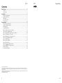
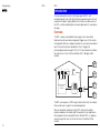
Programming
SD1+
SD1+
Speech Dialler
Cooper Security Ltd
Security House
Vantage Point Business Village
Mitcheldean
Gloucestershire
GL17 0SZ
www.coopersecurity.co.uk
Product Support (UK) Tel: +44 (0) 1594 541979.
Available between:
08:15 and 17:00 Monday to Friday.
Product Support Fax: (01594) 545401
Part No: 11832027
34
Installation and
Programming Guide
SD1+
Contents
SD1+
Programming
NOTES:
Introduction........................................................................................................ 1
Overview ............................................................................................................................ 1
Specifications ..................................................................................................................... 4
Installation.......................................................................................................... 5
Installation Requirements ................................................................................................... 5
Mounting Instructions......................................................................................................... 5
PCB Layout........................................................................................................................ 5
SD1+ Connections............................................................................................................. 6
Commissioning .................................................................................................................. 9
Programming ................................................................................................... 11
Entering Programming Mode ........................................................................................... 11
Leaving Programming Mode ............................................................................................ 11
Initialising a Unit................................................................................................................ 11
Programming Options ...................................................................................................... 13
Option 1: Storing Telephone Numbers........................................................................... 14
Option 2: Recording Messages...................................................................................... 18
Option 3: Erasing Messages/Telephone Numbers ......................................................... 20
Option 4: Changing Your Passcode............................................................................... 21
Option 5: Changing Your Passcode Type ...................................................................... 22
Option 6: Programmable Output.................................................................................... 23
Option 7: Call Routing.................................................................................................... 24
Option 8: Abort Options................................................................................................. 25
Option 9: Last Call Log .................................................................................................. 26
Option 0: Acknowledgement Options ............................................................................ 27
Options ABCD: Testing Messages............................................................................ 28
Display Messages ............................................................................................................ 29
Trouble Shooting Guide ................................................................................................... 30
© Cooper Security Limited 2008
Every effort has been made to ensure that the contents of this book are correct. However, neither the authors nor Cooper Security Limited
accept any liability for loss or damage caused or alleged to be caused directly or indirectly by this book. The contents of this book are subject to
change without notice.
Should the content of this manual not reflect the core functions of the product please let us know. You may be able to obtain more recent issues
of this manual on: www.coopersecurity.co.uk
Printed and published in the UK.
ii
33
Programming
NOTES:
SD1+
SD1+
Introduction
This manual describes how to install and program all SD1+ units
manufactured after June 2008. Note that the programming menu for units
made after that date is slightly different from the menu in older versions of
the SD1+, and the recording time has been lengthened to 25 seconds per
message.
Overview
The SD1+ sends pre-recorded voice messages over a conventional
telephone line whenever external equipment triggers one of its four inputs.
Any equipment that has a voltage-free contact as an output can provide an
input to the unit. Each input, labelled A, B, C or D, triggers the
corresponding stored message A, B, C or D. In the example shown below
these inputs are: A- fire, B- Personal Attack (PA), C- Burglary and DAuxiliary.
Tel No 1
A
B
C
D
Auxiliary
Input
Telephone
Tel No 2
SD1+
Alarm system control
unit (or other
equipment)
A
1
2
B
4
5
C
7
8
9
D
ENT
0
ESC
3
6
Tel No 3
BT Line
Speech Dialler
Tel No 4
The SD1+ also requires a 12VDC supply. Alarm control units, for example,
often provide such a supply for connected equipment.
When connected to a telephone line the SD1+ behaves like another
extension and does not normally affect the operation of any telephone or
other equipment also connected to the line. While the SD1+ is sending a
voice message other users on the line will hear it should they lift their
handset.
32
1
Introduction
SD1+
SD1+
Programming
RECORDING MESSAGES
Problem
Possible Cause
Action
The SD1+ has a built in microphone to let you record messages directly
into the unit.
The recipient can’t
acknowledge the call
with a mobile phone.
Weak reception or
incompatible telephone.
Mobile phones will only work
correctly if they are used in an
area where the reception is good.
Each message comprises two phrases: a common phrase (labelled ‘0’)
and one of phrases A, B, C or D. The common phrase normally tells the
recipient where the message comes from, and the second phrase tells the
recipient what input has been activated.
Each phrase can be up to 25 seconds long.
PLAYING BACK MESSAGES
The unit’s built-in speaker lets you hear any of the recorded messages.
When you play a message, the SD1+ always plays phrase 0 first.
TELEPHONE NUMBERS
The SD1+ can store up to four different telephone numbers, each one up
to 24 digits long. You can program and check the numbers from the unit’s
keypad and display.
The “CLEARBY” option is Check that the option is at the
The recipient has
acknowledged the call set to: “ANY-2” or “ANY- required setting.
3” or “ALL-4”
but the SD1+
continues to dial the
second, third or fourth
number.
I am pressing the [
key for 6 seconds, but
I cannot get the
“READY” prompt and
the display still shows
“PLEASE RECORD” or
“SD1+”.
You must key in a four
digit passcode to gain
access to the
programming menu.
Enter your user passcode (page
11).
The SD1+ uses pulse or tone dialling, and you can insert pauses for slowresponding exchanges.
You can also program the SD1+ to send numerical messages to pagers.
The unit adds a single digit at the end of the pager message to indicate
which input has been triggered.
DELETING MESSAGES AND TELEPHONE NUMBERS
The SD1+ stores the recorded messages and telephone numbers
internally, and you cannot delete them simply by removing the power
supply. A programming option allows you to delete all messages or
telephone numbers at once if you wish to do so, or you can delete them
individually.
CALL ROUTING
You can program the SD1+ so that each trigger input will send its
associated message to any of the stored telephone numbers. For
example, if you wish the unit to call four different numbers under three
different conditions you could program trigger A to call telephone number
1, trigger B to call telephone numbers 2 and 3, and trigger C to call
telephone numbers 1, 2, 3 and 4.
2
31
Programming
SD1+
Problem
Possible Cause
Action
The SD1+ will not
trigger from the alarm
panel.
Incorrect polarity setting.
Check that the jumper link is set
to the correct position (see page
7).
Incorrect trigger voltage.
Measure trigger voltage and
check connections (see page 7).
The SD1+ does not
display anything except
for “SD1+” whilst it is
triggered.
To see the status of the SD1+
when triggered use the “Test Call”
option (page 28).
The unit will not dial the Number entered
programmed telephone incorrectly.
number.
The unit is dialling out
through an internal
telephone exchange
(PABX) that needs a
pause after initial “9”.
Check that you have keyed-in the
number correctly.
Make sure that you have
programmed a pause into the
number after the initial “9” (page
14).
The unit is wired to an
The unit cannot be with this type
exchange that needs a
of exchange. Connect it to a
special button pressed to standard BT line.
select a line.
Incorrect telephone line
connections.
The recipient of the call Incorrect
cannot acknowledge acknowledgement
the unit by pressing the procedure.
“8” button.
The recipient is using an
incompatible telephone.
30
Introduction
THREE WAY CALLING
Trouble Shooting Guide
An input has triggered
the unit but the display
shows “SD1+” all the
time.
SD1+
Check the connections to the
telephone line (see page ).
Instruct the recipient in the correct
procedure (see pages 3 and 27).
This is a service normally provided by British Telecom. If the service is
enabled then the SD1+ will use it to prevent anyone trying to block the
telephone line.
CALL ATTEMPTS
When triggered the SD1+ rings a programmed number and waits 55
seconds (about 20 rings) for an answer. If the called phone does not
answer then the SD1+ hangs up and tries again immediately. If the called
number does not answer for a second time the SD1+ hangs up and waits
five seconds, then calls again for the last time. If the destination still does
not answer the SD1+ hangs up and operates the Fail output (if
programmed) for seven seconds.
ACKNOWLEDGEMENT OPTIONS
Once the SD1+ has made a call and delivered a message, it needs a
return signal to show that the message has been successfully received. If a
person is taking the call they can acknowledge the message by pressing
the number “8” on the their telephone keypad. When the SD1+receives a
digit “8” it will stop attempting to send that message until it is triggered
again. You can program how many times each message must be
acknowledged.
LAST CALL LOG
The SD1+ keeps a log of the last call it has made. The log also shows
which input was triggered last.
CALL ABORT
If required, you can program the SD1+ so that one of the following events
will abort a call:
Applying a signal to the Abort input (shared with input D).
Call the recipient and ask them to
press the “8” button on their
telephone. If you hear anything
other than a tone, the telephone is
not capable of acknowledging the
SD1+. This may be overcome by
using a tone pad to simulate the
dialling tones. Contact your
installation company for details.
Removing the input that triggered the unit.
Keying in the user passcode.
When aborted the unit will stop dialling out immediately, play a chime tone,
and show “ABORTED” on the display for a few seconds.
PROGRAMMABLE OUTPUT
The SD1+ has a single programmable output. When active the output
applies 0V to its terminal and is capable of sinking up to 100mA of current.
3
Introduction
SD1+
You can program the SD1+ to activate the output for one of the following
conditions:
The unit has been triggered and is making calls. The output is active
from the trigger event until the last required acknowledgement, or
until the whole series of calls has failed.
A call has been successfully acknowledged. The output is active for
seven seconds when the unit receives the last required acknowledge
signal.
SD1+
Display Messages
PLEASE
RECORD
SD1+
ABORTED
The SD1+ failed to communicate. The output is active for seven
seconds when the SD1+ finally stops calling.
SENDING A TEST CALL
Once programmed you can test each message by sending it to a selected
telephone number. When the unit is in test mode the speaker relays
everything that the unit sends over the telephone line, and the display gives
a visual indication of what is happening.
PASSCODE
To enter programming mode or to cancel calls you must key in a passcode
at the keypad. The passcode is normally four digits long, but if necessary
you can program the SD1+ to accept six-digit passcodes for greater
security.
Power input:
11.5V - 14V
Current consumption: 35mA (standby); 70mA (Active)
Trigger inputs:
A, B, C, D (+ve or -ve applied, input voltage 5 28V)
Phrases A,B,C,D,0:
25 seconds ± 2 seconds each, sampled at 8KHz
Telephone Numbers:
4 x 24 digit telephone numbers
Case dimensions:
150(L) x 104(H) x 30(D) mm
REN value:
0
4
The unit has no stored messages or telephone
numbers.
Either: The unit is in normal standby OR: the unit is
dialling out after an input has triggered it.
A user keyed in a passcode to abort a call while the
SD1+ was attempting to dial out. The unit displays this
message for aborted activations, but NOT for aborted
test calls.
The unit displays the following messages during a test call, but NOT
during a normal activation:
RINGING
The unit has detected a ringing signal on the telephone
line.
ENGAGED
The target phone is engaged. Wait until they have
finished and try again.
UNOBTAIN
The unit has detected the Unobtainable or Special
Information Tone. Check that the number is correct
and try again.
SENT OK
Specifications
Programming
NO REPLY
PAGED
The unit dialled out, sent the message and was
acknowledged correctly by the recipient.
The call was not answered or acknowledged by the
recipient.
If you have programmed the unit to send a pager
number, the SD1+ will show this message when it has
sent the pager message.
29
Programming
SD1+
Options ABCD: Testing Messages
Installation
Installation Requirements
To test a message and it’s telephone numbers:
1. Make sure the SD1+ is not currently sending any
messages.
SD1+
2. Key in the current passcode.
READY
3. Press either A, B, C or D depending on which
message you want to test. The display shows, for
example “SEND A” alternating with “ON 1-4”:
SENDa A
ON 1-4
EITHER:
A) Press A.
PHRASE A
The unit plays message 0 followed by message A.
The display shows, for example “PHRASE A”:
Z
Cooper Security supplies the SD1+ with a 2 metre telephone lead which
will plug directly into any standard BT socket. Cooper Security recommend
that you site the SD1+ as near to a BT telephone socket as possible. If this
it not possible you can either use an approved BT extension lead or wire
the unit to the BT. socket (see page 8).
Mounting Instructions
2. Hold the base in position (keyhole to the top) and mark the three
securing holes. Remove the base then drill and plug the holes.
READY
3. Pass all cables into the base through the cable entries and then secure
the base to wall.
PCB Layout
OR:
B) Press a digit 1 to 4. The SD1+ sends message 0
and the message A (or B or C or D depending on the
key you pressed in step 3) to the telephone number
you selected (1 to 4).
Z
The SD1+ is designed for connection to an intruder alarm control panel or
similar equipment. The control panel must have an auxiliary power output
of between 11.5V and 14V, with the ability to provide a minimum of
100mA.
1. Separate the cover from the base by using a screwdriver to push two
of the retaining clips (top or bottom) inwards from the base indents.
Remove cover assembly and store in a safe place.
If you wait five seconds without pressing a key then
SD1+ plays message 0 followed by the message
associated with the key you pressed in step 3.
Once the SD1+ has finished playing the messages
the screen shows “READY”:
SD1+
Note: Ask the person answering the call to
acknowledge the message by pressing ‘8’ on their
phone keypad. Otherwise the SD1+ will work
through a complete cycle of four calls for that
message.
1. Loudspeaker
2. Tamper Switch
3. Microphone
4. Tamper connections (SELV)
5. Trigger Inputs (SELV)
6. Trigger Polarity jumper
7. Telephone Connections (TNV)
8. 12V Supply and Programmable
O/P (SELV)
9. Factory Restart Pins
SELV = Safety Extra Low Voltage, TNV= Telecommunications Network Voltage.
28
5
Installation
SD1+
SD1+
Programming
SD1+ Connections
Option 0: Acknowledgement Options
Caution: Before making any connections to the SD1+ remove the
power (battery and 240V mains) from the equipment you intend to
connect the unit to.
Once the SD1+ has made a call and delivered a
message, it needs a signal to say that the message has
been successfully received. This is done by the recipient
pressing the number “8” on their telephone. When the
SD1+ receives the “8” it stops attempting to send that
message until triggered again.
Z
Connections on the SD1+ are either “Safety Extra-Low Voltage”
circuits (SELV) or “Telecommunication Network Voltages” circuits
(TNV). Connect TNV circuits only to the PSTN. Connect SELV circuits
only to other circuits designated as SELV circuits.
Z
Route cabling to the telephone line connections (TNV) well away from
the trigger input circuitry (SELV). Route cabling to the trigger input
circuitry (SELV) well away from the telephone circuitry (TNV).
The SD1+ provides the following connections:
Trig Inputs (see figure on page for connection diagram):
A:
When triggered, the unit starts the dialling sequence and sends
message A.
B:
When triggered, the unit starts the dialling sequence and sends
message B.
C:
When triggered, the unit starts the dialling sequence and sends
message C.
Option 0 determines how many calls must be
acknowledged before the SD1+ stops attempting to
send a message.
1. If necessary initialise the SD1+ .
2. Key in the current passcode.
3. Press 0, the display shows:
4. Press [, the display shows the current
acknowledgement option, for example:
The options available are:
You can select Trigger/Abort inputs to be either +ve applied to trigger
or -ve applied to trigger. Set the “Trigger Polarity” jumper-link to the
appropriate position (see figure on page ).
TAMP:
These two voltage free terminals are connected directly to the
normally closed tamper switch. You can connect them to the
main tamper zone on the alarm control panel, to provide case
tamper protection for the SD1+.
0V:
Connect to a permanent 0V supply on the control panel.
+12V:
Connect to a permanent +12V supply on the control panel.
O/P1:
A switched -ve @100mA programmable output (see page 23).
6
READY
CLRBYANY-1
“ANY-1” at least one call must be acknowledged.
“ANY-2” at least two calls must be acknowledged.
ABORT/D: If the SD1+ is programmed as “ABORT by INPUT” this
connection can be used to abort the dialling sequence. If the
SD1+ is not programmed as “ABORT by INPUT” this
connection can used as trigger input D.
Z
SD1+
“ANY-3” at least three calls must be acknowledged.
“ANY-4” all four calls must be acknowledged.
“NO-ONE” no acknowledgement required.
5. Press B repeatedly until the display shows the option
you want to use, for example:
5. Press [ to save the change and return to “READY”.
Z
ANY-2
READY
Note: If you select NO-ONE and also program the output as FAILED
(see page 23 ) then the output will not operate.
27
Programming
SD1+
Option 9: Last Call Log
2. Key in the current passcode.
3. Press 9, the display shows:
+
+
-
SD1+
SD1+
READY
VIEWLOG-
N.O.
Loop
N.C.
Loop
TRIG A
TRIG B
TRIG C
1K
resistor
+12V
0V
N.C.
Loop
N.O.
Loop
SD1+
TRIG A
TRIG B
TRIG C
+12V on alarm
TRIG A = Normally Closed Input
TRIG B = Normally Open Input
TRIG C = Switched +ve Input
-
1K
resistor
0V on alarm
TRIG A = Normally Open Input
TRIG B = Normally Closed Input
TRIG C = Switched -ve Input
CONTROL PANEL CONNECTIONS
A)--3-
If the display shows:
“A)----“ then none of the calls for message A were
acknowledged.
“BLANK” then the log is empty.
5. Press [ to return to “READY”.
TRIG POLARITY
+12V
0V
4. Press [.
The display shows the last event recorded by the
unit. In the example shown at the right, the unit sent
message A to telephone number 3, which
acknowledged the call.
Installation
TRIG POLARITY
Once someone has acknowledged a call, the SD1+
stores a record of the event. You can see that record
using option 9.
1. If necessary initialise the SD1+ .
SD1+
READY
The table below lists the connection details to various control panels.
Control Panel
TRIG A
Menvier TS400/TS410
Menvier TS510
Menvier TS690R
Menvier TS690/TS700
Menvier TS790/TS900/TS2500
A1 Advantage
ADE Optima XM
ADE Optima 2+
ADE Concept 6
ADE Accenta 6
Ademco Infra 6
Ademco Infra 16
C & K 700L
CQR Premia 9
DA Abacus 6
DA Abacus 8
Gardtec 500 Series
Gardtec 800 Series
JSB Regent
Pyronix Paragon + /E
Pyronix Octagon
Pyronix Conqueror
Scantronic 9448
Scantronic 9452/3
Scantronic 9454
Scantronic 9455
Texecom Veritas R8
Texecom Veritas 8 Compact
Zone 4
N/A
OP 1
Digi 1
Digi 1
N/A
N/A
Fire
N/A
N/A
N/A
1*
N/A
FA *
N/A
N/A
N/A
D1 *
COM1
N/A
N/A
N/A
N/A
N/A
N/A
N/A
N/A
N/A
TRIG B
Fire
Zone 5
OP 2 *
OP 2
Digi 2
Digi 2
N/A
N/A
PA
N/A
N/A
N/A
2
N/A
PA
N/A
N/A
N/A
PA
COM2
N/A
PA
N/A
COM 2
COM 1
COM 1
COM 1
N/A
N/A
TRIG C
PA
ALM
OP 1 *
OP 3
Digi 3
Digi 3
Bell B
Intruder
B
B
3
3
SIA
Bell
Bell
Bell 12Hr
COM3
BA
ALM
BA
COM 3
COM 3
COM 3
COM 3
B
B
Polarity
Supply +
Supply -
+
+
+
+
+
-
Aux +
Aux +
Aux +
Aux +
Aux+
Aux +
13V +
13V +
13V +
13V +
Aux +
Aux +
Aux +
Aux 12V
+12V
+12V
Power +
12V
12V
Aux +
Aux +
Aux +
12V
Aux 12V
12V
12V
Aux +
Aux +
Aux Aux Aux Aux Aux Aux 13V 13V 13V 13V Aux Aux Aux Aux 0V
0V
0V
Power 0V
0V
Aux Aux Aux 0V
Aux 0V
0V
0V
Aux Aux -
Trigger
Type
0V app.
12V app.
0V app.
0V app.
0V app.
0V app.
0V app.
0V app.
0V app.
0V app.
12V app.
12V app.
0V app.
12V app.
0V app.
0V app.
0V app.
0V app.
12V app.
0V app.
0V app.
0V app.
5V rem.
5V rem.
5V rem.
5V rem.
0V app.
0V app.
* Control panel output requires programming.
26
7
Installation
SD1+
When using the bell output to trigger the SD1+, you may find that the
external sounder is partially triggered. If this is the case you will need to fit a
1k resistor between the SD1+ trigger input and 12V.
BT. CONNECTIONS
1. Connect telephone line using one of the methods shown below:
2. Replace the plastic cover over the telephone line connections.
SD1+
Programming
Option 8: Abort Options
Occasionally you may trigger the SD1+ by accident and
cause it to send an unwanted call. Option 8 allows you
to select one of three methods of cancelling a call:
“INPUT”
applying a signal to the Abort input.
“RESTORE” removing the trigger signal.
“PASSCODE”
entering the passcode.
You can also prevent anyone cancelling a call by
selecting “NONE”.
1. If necessary initialise the SD1+ .
2. Key in the current passcode.
3. Press 8, the display shows:
SD1+
READY
ABORT-
4. Press [.
The display shows the current method used to
cancel a call, for example:
INPUT
5. Press B repeatedly until the display shows the
method that you want to use, for example:
PASSCODE
6. Press [ to store the change and return to “READY”.
8
READY
25
Programming
SD1+
SD1+
Installation
Option 7: Call Routing
Commissioning
You can program messages A, B, C or D so that they
report to one or more of the four telephone numbers. For
example: message A might report to telephone numbers
1, 3 and 4, but NOT to number 2.
Once you have made all the necessary connections, fit the cover back
onto the base and apply power to the SD1+.
1. If necessary initialise the SD1+ .
2. Key in the current passcode.
3. Press 7, the display shows:
SD1+
READY
ROUTE-
4. Press [.
The display shows the telephone numbers that
message A reports to. In the example on the right,
message A goes to telephone numbers. 1 and 3.
5. Press 1, 2, 3 or 4 until the display shows the
telephone numbers that you want the message A to
go to, for example:
6. Press B repeatedly to see what destinations the
other messages go to, for example:
A)1-3A)-2-4
C)---4
Key in 1234.
PLEASE
RECORD
READY
The SD1+ is now in programming mode. The display
shows:
Z
If you do not operate the unit for 60s then it will leave
programming mode by itself. Simply key-in the
passcode again to re-enter programming mode.
If you are unfamiliar with programming a SD1+, then here
is a list of the minimum items you must program in order
to get the unit working.
Store the telephone number of the person you wish
to receive the message (page 14).
Record Phrase 0, giving the location of the unit, or of
the equipment being monitored (page 18).
7. Repeat steps 5 and 6 until you have allocated all the
messages to their correct telephone numbers.
8. Press [ to accept the new option and return to
“READY”.
When you power up a new SD1+ for the first time the
memory is blank: there are no stored telephone numbers
or messages. When there are no stored messages or
telephone numbers the display shows:
READY
Record a phrase for each input A, B, C or D that is
connected to the unit (page 18).
Test the message and destination by starting a test
call (page 28).
Tell the person who is going to receive the call how
to acknowledge it (press ‘8’ on their telephone
keypad, see page 3).
If you wish to allow a user to abort a call then see
page 25.
Once you have finished programming and testing the
unit, press ] until the display shows:
SD1+
The SD1+ is now in standby mode, ready for operation.
24
9
Installation
While the SD1+ is in standby the display continues to
show “SD1+” You can re-enter programming mode if
you need to by keying in the passcode.
When the SD1+ is making a call, the display continues to
show “SD1+” but the unit will not allow you to enter
programming mode. If you have programmed the unit to
allow a user to abort the call, then entering the passcode
will stop the call immediately.
The following pages tell you how to program the unit in
more detail, and how to set up some of the more
complex functions.
SD1+
SD1+
Programming
Option 6: Programmable Output
The SD1+ has a single output. Using option 6 you can
program this output to operate under one of the
following conditions:
a) When an active input triggers the unit (the display
shows this as “ACTIVE”).
b) When someone acknowledges a call from the SD1+
(shown as “SUCCESS”).
c) When the SD1+ has dialled all numbers but has NOT
been acknowledged (shown as “FAILED”).
Z
If you wish to disable the output, you can set it to
“OFF”.
1. If necessary initialise the SD1+ .
SD1+
2. Key in the current passcode.
READY
3. Press 6, the display shows:
OUTPUT-
4. Press [.
The display shows the current output type, for
example:
5. Press B. until the display shows the output type
you want to use, for example:
SUCCESS
6. Press [ to accept the new option and return to
“READY”.
READY
Z
10
ACTIVE
Note: If you select FAILED, and also set the acknowledgement option
to NO-ONE (see page 27 ) then the output will not operate.
23
Programming
SD1+
Option 5: Changing Your Passcode Type
When delivered from the factory, (or if you have just
initialised the unit) the SD1+ uses four-digit passcodes. If
you want to use a longer passcode, use option 5 to set
up six-digit passcodes.
Z
To gain access to the program menus you must key in a
passcode. The default passcode is 1234.
When you change from four-digit to six-digit
passcodes SD1+ adds “00” to the end of your
current passcode.
2. Key in the current passcode.
3. Press 5, the display shows:
If the SD1+ is using six digit passcodes the display
shows:
5. Press B. until the display shows the code length
you want to use, for example:
6. Press [ to accept the new passcode length and
return to “READY”.
SD1+
2. Key in your user code, for example 1234. The
display shows:
READY
Leaving Programming Mode
1. Make sure the SD1+ is at the top level of the
programming menu (the screen shows “READY”).
SD1+
READY
C,TYPE-
4. Press [.
If the SD1+ is currently using four-digit passcodes
the display shows:
1. In stand-by mode (not communicating) the display
shows:
The SD1+ is now in programming mode.
If you change from six-digit to four-digit passcodes,
SD1+ removes the last two digits from the end of
your current passcode.
1. If necessary initialise the SD1+ .
Programming
Entering Programming Mode
If you want to change back from six-digit to four-digit
passcodes, use option 5 again.
Z
SD1+
4, CODE
6, CODE
6, CODE
READY
2. Press ]. The screen shows SD1+ and you have left
programming mode.
SD1+
Initialising a Unit
When you power up a new SD1+ for the first time the
memory is blank and the display shows “PLEASE
RECORD”. Once you have stored messages and
telephone numbers in the unit the display shows “SD1+”
when you return to standby mode. If you want to return a
unit to its blank state you can initialise it as follows:
PLEASE
RECORD
1. Remove all power from the unit.
2. Hold down 9 and reapply power. Release 9.
The display shows:
ERASE?
3. Press [. The display shows:
LANG ?
4. Press ].
The display shows:
PLEASE
RECORD
5. Key in the default pass code 1234.
The display shows:
22
READY
READY
11
Programming
The SD1+ is now in programming mode. It has no stored
messages or telephone numbers. The passcode is
1234.
Note: If you wish, you can also initialise the unit as
follows:
1. Remove all power from the SD1+ .
2. Fit a jumper to the reset pins (see page ).
3. Apply power to the SD1+.
4. Remove the jumper from the reset pins.
SD1+
SD1+
Option 4: Changing Your Passcode
To change the programming of the SD1+ you must first
key in a passcode. In addition, you can use the same
passcode to abort a call if it was started by accident (and
if the SD1+ if programmed to allow you to do so, see
page 25).
When delivered from the factory (or if you have initialised
the unit) the passcode is 1234. Use option 4 to
change your passcode to another set of digits. The
passcode is normally four digits long, but you can make
it six digits long (see page 22).
1. If necessary initialise the SD1+ .
SD1+
2. Key in the current passcode.
READY
3. Press 4, the display shows:
NEWCODE-
4. Press [. The display shows a line of dashes:
----
5. Key in your new passcode, for example 2580.
2580
6. Press [ to store the new passcode and return to
“READY”.
12
Programming
READY
21
Programming
SD1+
Option 3: Erasing Messages/Telephone
Numbers
If you wish to record a new set of phrases, or store a
new set of telephone numbers, you must first delete the
old ones. This option allows you to delete either
telephone number or phrases without initialising the
SD1+ again.
1. Key in the current passcode.
2. Press 3. The display shows “ERASE-“ alternating
with “MSG/NUM” .
3. Press [. The display shows:
4. Press B repeatedly to display either “MESSAGES” or
“NUMBERS”, for example:
5. Press [ to delete all the entries.
If you selected “NUMBERS” in step 5 then the SD1+
deletes all telephone numbers. If you selected
“MESSAGES” in step 5 then theSD1+ deletes all
messages.
The display now shows “READY”.
Programming
Programming Options
There are 10 programming options, one assigned to each number key.
The keys A, B, C and D allow you to test the messages and telephone
numbers that you program in. The table below lists the available options,
and the page in this guide which describes each of them in more detail.
Key Option
Display
Page
1
Store telephone numbers 1 to 4
ENT 1-4
14
2
Record Messages (home plus A to D)
ENT 0-D
18
3
Erase messages or telephone numbers
ERASE-
20
MSG/NUM
4
Change passcode
NEWCODE-
21
MESSAGES
5
Change passcode length
C, TYPE
22
NUMBERS
6
Program output
OUPTUT-
23
7
Call routing
ROUTE-
24
8
Abort options
ABORT-
25
9
View event log
VIEWLOG
26
0
Acknowledgement
CLEARBY-
27
A
Test message A
SEND A
28
B
Test message B
SEND B
28
C
Test message C
SEND C
28
D
Test message D
SEND D
28
READY
ERASE-
READY
Z
If you want to delete individual telephone numbers use option 1, see
page 14.
Z
If you want to record over an individual phrase, you can do so. Use
option 2, see page 18.
20
SD1+
13
Programming
SD1+
Option 1: Storing Telephone Numbers
6. Press [ again to stop recording. The display shows
“ENT 0-D”:
SD1+
2. Key in the current passcode.
READY
3. Press 1. The display shows:
ENT 1-4
4. Press 1, 2, 3 or 4 to select telephone number
1, 2, 3 or 4. The display shows “TEL NO “ alternating
with the digits stored, for example:
If you wish to erase all the digits stored for that
number press A.
The screen shows “BLANK” if the SD1+ does not
have any digits stored for a number.
5. Key in the digits you wish to store.
Programming
The display shows “REC” and a number:
The number counts down in seconds from 25 to
show you the amount of time you have left for the
phrase.
The SD1+ stores up to four telephone numbers, each up
to 24 digits long. Make sure that you obtain permission
from the person being called before storing their
telephone number. DO NOT use the SD1+ to call the
Police using an Emergency Service telephone number.
1. If necessary initialise the SD1+ .
SD1+
ENT 0-D
7. Repeat steps 4, 5 and 6 to record the other phrases
you need.
8. Press [ again to return to “READY”.
READY
TEL NO 2
12345678
9012334
98765432
You can key in up to 24 digits for each number.
Key in BC if you want to enter a dial pause. The
pause appears as a comma on the display, for
example:
9,8765432
Each pause you enter causes the SD1+ to wait three
seconds before dialling the rest of the telephone
number.
If you wish to correct a mis-keyed digit:
a) Press A to move the cursor left.
b) Key in the new digit.
c) Press C repeatedly to move the cursor to the
right hand end of the telephone number. You can
now continue adding more digits to the end of the
14
19
Programming
SD1+
Option 2: Recording Messages
6. Press [ to store the new telephone number and
return to “ENT 1-4”.
7. Press [ again to return to “READY”.
It is also advisable to include the instruction “Press 8 to
acknowledge” at the end of each of phrases A to D. For
example:
Before you record the phrases it is a good idea to write
down what you intend to say.
Note that the SD1+ can hold up to 25 seconds of sound
for each phrases.
18
To comply with BABT regulations do NOT program any two
telephone numbers to be the same.
Z
Do NOT program the SD1+ to call the Police using the Emergency
Services telephone numbers.
Each pager service has its own requirements for pauses,
star and hash. You may have to experiment to find the
correct combination for the service you are using.
To record a phrase:
5. Press [. SD1+ starts recording.
Speak clearly.
Stand about 15 to 20 centimetres from the unit.
Z
When dialling a pager the SD1+ may have to wait before
sending the message. To insert a pause enter “M” after
the pager number. When the paging equipment answers
the call, the SD1+ can send the message as normal, or
precede it with a “star” or “hash”. The SD1+ always
terminates a pager message with a “hash”.
Phrase A: “The alarm has been activated. Please press
8 after the beep to acknowledge this call.”
4. Press 0, A, B, C or D to select the phrase you
want to record. The display shows the word
“RECORD” alternating with the word “PHRASE” and
the phrase letter, for example:
READY
PROGRAMMING PAGER MESSAGES
Phrase 0: “This is Mr Smith, at 10 The Strand, East
Fincham.”
3. Press 2. The display shows “ENT 0-D”.
ENT 1-4
At this point you can select any phone number by
pressing keys 1, 2, 3 or 4.
Normally you should use phrase 0 to store the name and
address of the premises. Use phrases A to D to store a
short name for the condition triggering them (for example
“Alarm” or “Fire”).
2. Key in the current passcode.
Programming
number (or correct any other digit).
The SD1+ can transmit up to four messages. A message
is made up of two phrases: phrase 0 plus one of phrases
A, B, C or D. Each trigger (A, B, C or D) is linked to one
of the phrases A, B, C or D.
1. If necessary initialise the SD1+ .
SD1+
SD1+
READY
ENT 0-D
RECORD
PHRASE A
REC - 39
1. If necessary initialise the SD1+ .
SD1+
2. Key in the current passcode.
READY
3. Press 1.
ENT 1-4
4. Press 1, 2, 3 or 4 to select telephone number
1, 2, 3 or 4. The display shows “TEL NO “ alternating
with the digits stored, for example:
If you wish to erase all the digits stored for that
number press A.
TEL NO 2
9012334
The screen shows “BLANK” if the SD1+ does not
have any digits stored for a number.
15
Programming
SD1+
5. Key in the phone number of the pager, for example:
08323456
6. Key in BBBBC. The display shows an “M” at
the end of the telephone number:
8323456M
Z
Z
Z
Z
SD1+ always adds a “#” (hash) at the end of a pager
message. You do not have to key one in yourself.
8. Press [. The display returns to “ENT 1-4”.
Programming
TONE
DIALLING
PULSE
DIALLING
456M333
(If you press B again the display changes to show
the words AUTO, see the note below.
If you wish the message to start with a “*” key in
BBC. If you wish the message to start with a “#”
key in BBBC.
SD1+ adds a single digit to the end of the message
to indicate the trigger, for example “1”=trigger A.
4. Press D. The display alternates between the words
“TONE” and “DIALLING”.
5. Press B. The display changes to show the words:
The pager treats anything you key in after the “M” as
the message.
7. Key in the paging message (for example 333 for
alarm):
SD1+
Press B again to go back to TONE DIALLING.)
6. Press [ when the display shows the option you
want.
TEL NO 2
The display shows the telephone number you
selected in step 3.
ENT 1-4
If you now display the telephone number, you will
see a star or hash following the “M”, depending on
what you selected in step 7.
7. Press [ again. The display shows:
ENT 1-4
8. Press [ once more. The display returns to:
READY
Z
Note: If you select AUTO, SD1+ will automatically
select the correct dialling format itself.
PULSE DIAL OR TONE DIAL
Some telephone systems may still use pulse dialling. If
you need to change from tone dialling to pulse dialling for
any phone number, carry out the following steps.
1. Key in the current passcode.
READY
2. Press 1.
ENT 1-4
3. Press 1, 2, 3 or 4 to select the telephone
number you wish to make pulse dialling, for example:
16
TEL NO 2
17