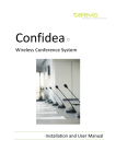
1
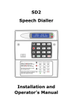
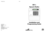
SD1+ Speech Dialler SD1+ SD1+ A 1 2 3 B 4 5 6 C 7 8 9 D ENT 0 ESC Installation Instructions 1. Overview A B C Tel No 1 D Auxiliary Input Telephone Tel No 2 1 3 4 2 UNSET TAMPER FINAL EXIT 1 4 2 5 7 8 0 HOME 3 6 9 AWAY 5 SD1+ A 1 2 B 4 5 C 7 8 3 9 D ENT 0 ESC 6 Tel No 3 BT Line Control Panel Speech Dialler Tel No 4 Connections: The SD1+ is connected between the alarm control panel and the telephone line. It behaves like another extension to the telephone and does not affect its normal operation or that of any other extension fitted. The unit requires no batteries as its power and mains fail back-up are derived from the alarm control panel. The SD1+ accepts three trigger inputs which in our example are; A - Fire, B - Personal Attack (PA), C - Burglary and D - Auxiliary. These inputs correspond to the messages (A, B, C or D) that the SD1+ sends out and should be recorded as such. The SD1+ can also accept a direct connection from suitable auxiliary devices such as radio PA buttons, medical alarms or anything using voltage free contacts. Telephone Numbers: The SD1+ will dial up to four different telephone numbers and play its message. The numbers may be up to 24 digits long and are simply programmed using the text display and keypad on the unit. The SD1+ also supports pager numbers. Note: The SD1+ must NOT be used to call the Police via the Emergency Services phone numbers. Messages: The SD1+ has a built-in microphone and speaker so that messages can be recorded and replayed directly from the unit. When the outgoing call is answered the SD1+ plays a common phrase (0) and one of the three alarm messages (phrases A, B or C). Phrase 0 normally states the name and address of the site and phrases A, B and C relate to the inputs from the control panel (Fire, PA, and Burglary in our example). A total of 40 seconds is available for recording messages. Acknowledgement: On receiving a call from the SD1+ the person answering the call can acknowledge it by pressing number [8] on their telephone. If the message is not acknowledged then it is repeated four times after which the SD1+ abandons the call. The SD1+ has several acknowledgement options which allows the unit to stop dialling after the first call has been acknowledged or when two or three have been acknowledged. Abort: The SD1+ has several abort options which include applying a signal to the abort input, restoring the trigger input or by entering the operators passcode. When the unit is aborted it immediately shuts down and returns to its normal standby mode. 2. Installation Requirements The SD1+ has been designed to be connected to an intruder alarm control panel or similar. The control panel must have an auxiliary power output of between 11.5V and 14V, and the ability to provide a minimum of 100mA. The unit is supplied with a 2 metre telephone lead which will plug directly into any standard BT socket and it is therefore recommended that the unit is sited as near to a BT telephone socket as possible. If this it not possible an approved BT extension lead may be required or the unit can be hard wired to the BT. socket (see section 8). 3. Mounting Instructions 1. Separate the cover from the base by using a screwdriver to push two of the retaining clips (top or bottom) inwards from the base indents. Remove cover assembly and store in a safe place. 2. Hold the base in position (keyhole to the top) and mark the three securing holes. Remove the base then drill and plug the holes. 3. Pass all cables into the base through the cable entries and then secure the base to wall. 4. PCB Layout TAMP ABORT TRIG INPUTS C B A SD1+ O/P1 -ve A B A1 B1 TELEPHONE CONNECTIONS FACTORY RESTART TRIGGER POLARITY 12 34 + 0V +12V Loudspeaker Tamper Switch Microphone Tamper connections (SELV) Trigger Inputs (SELV) Trigger Polarity Telephone Connections (TNV) Country Setting (Not fitted on UK product) 12V Supply and Programmable O/P (SELV) Factory Restart Pins 5. SD1+ Connections Before any connections are made to the SD1+ remove the power (battery and 240V mains) from the control panel. Connections are provided as follows: TRIG A: When triggered, the unit starts the dialling sequence and sends message A. TRIG B: When triggered, the unit starts the dialling sequence and sends message B. TRIG C: When triggered, the unit starts the dialling sequence and sends message C. ABORT / D: If the SD1+ is programmed as “ABORT by INPUT” this connection can be used to abort the dialling sequence. If the SD1+ is not programmed as “ABORT by INPUT” this connection can used as trigger input D. Trigger/Abort inputs can be selected to be either +ve applied to trigger or -ve applied to trigger. Set the "Trigger Polarity" jumper-link to the appropriate position. TAMP: These two terminals can be connected to the main tamper zone on the alarm control panel, to provide case tamper protection for the SD1+. 0V: Connect to a permanent 0V supply on the control panel. +12V: Connect to a permanent +12V supply on the control panel. O/P1: A switched -ve @100mA programmable output. TRIG POLARITY + TRIG POLARITY + +12V 0V SD1+ TRIG A TRIG B TRIG C TRIG A = Normally Closed Input TRIG B = Normally Open Input TRIG C = Switched +ve Input + + N.C. Loop 1K resistor N.O. Loop +12V on alarm +12V 0V SD1+ N.O. Loop TRIG A TRIG B TRIG C 1K resistor N.C. Loop 0V on alarm TRIG A = Normally Open Input TRIG B = Normally Closed Input TRIG C = Switched -ve Input Connections on the SD1+ are described as ether "Safety Extra-Low Voltage" circuits (SELV) or "Telecommunication Network Voltages" circuits (TNV). Therefore it is important that installer ensures that TNV circuits are only connected to the PSTN and SELV circuits are only connected to other circuits designated as SELV circuits. Please ensure that cabling to the telephone line connections (TNV) are routed well away from the trigger input circuitry (SELV) and the cabling to the trigger input circuitry (SELV) are routed well away from the telephone circuitry (TNV). 6. Control Panel Connections The table below shows the connection details to various control panels. Control Panel TRIG A Fire TRIG B PA TRIG C Alarm Polarity Supply + Supply - Trigger Type Menvier TS400/TS410 Zone 4 Zone 5 ALM - Aux + Aux - 0V app. Menvier TS510 N/A OP 2 * OP 1 * + Aux + Aux - 12V app. Menvier TS690R OP 1 OP 2 OP 3 - Aux + Aux - 0V app. Menvier TS690/TS700 Digi 1 Digi 2 Digi 3 - Aux + Aux - 0V app. Menvier TS790/TS900/TS2500 Digi 1 Digi 2 Digi 3 - Aux+ Aux - 0V app. A1 Advantage N/A N/A Bell - - Aux + Aux - 0V app. ADE Optima XM N/A N/A B - 13V + 13V - 0V app. ADE Optima 2+ Fire PA Intruder - 13V + 13V - 0V app. ADE Concept 6 N/A N/A B - 13V + 13V - 0V app. ADE Accenta 6 N/A N/A B - 13V + 13V - 0V app. Ademco Infra 6 N/A N/A 3 + Aux + Aux - 12V app. Ademco Infra 16 1* 2 3 + Aux + Aux - 12V app. C & K 700L N/A N/A S- - Aux + Aux - 0V app. CQR Premia 9 FA * PA IA + Aux 12V Aux 0V 12V app. DA Abacus 6 N/A N/A Bell - +12V 0V 0V app. DA Abacus 8 N/A N/A Bell - +12V 0V 0V app. Gardtec 500 Series N/A N/A Bell - - Power + Power - 0V app. Gardtec 800 Series D1 * PA 12Hr - 12V 0V 0V app. COM1 COM2 COM3 + 12V 0V 12V app. Pyronix Paragon + /E N/A N/A BA - Aux + Aux - 0V app. Pyronix Octagon N/A PA ALM - Aux + Aux - 0V app. Pyronix Conqueror N/A N/A BA - Aux + Aux - 0V app. Scantronic 9448 N/A COM 2 COM 3 - 12V 0V 5V rem. Scantronic 9452/3 N/A COM 1 COM 3 - Aux 12V Aux 0V 5V rem. Scantronic 9454 N/A COM 1 COM 3 - 12V 0V 5V rem. Scantronic 9455 N/A COM 1 COM 3 - 12V 0V 5V rem. Texecom Veritas R8 N/A N/A B - Aux + Aux - 0V app. Texecom Veritas 8 Compact N/A N/A B - Aux + Aux - 0V app. JSB Regent + * Control panel output requires programming. When using the bell output to trigger the SD1+, you may find that the external sounder is partially triggered. If this is the case a 1K resistor will need to be connected between the SD1+ trigger input and +12V. 7. BT. Connections 1. Connect telephone line using one of the methods shown below: 2. Replace the plastic cover over the telephone line connections. Method 1 - Using the lead supplied SD1+ White Red A B Standard BT telephone plug Method 2 - Hard wired connections BT Master Jack (NTE5) User accessible connections Cable type 1/0.5mm CW1308 6 5 4 White/Blue 3 2 1 SD1+ Blue/White A B 8. Commissioning and Testing 1. If the SD1+ is not being used in the UK please ensure the options switch is set to the appropriate settings, see section 9. 2. Hold the blade of a small screwdriver between the “Factory Restart” pins (JP2) and switch the power back on to the control panel (battery and mains). 3. Remove the screwdriver blade and clip the SD1+ front cover onto the base taking care not to trap any cables. 4. The SD1+ "beeps" every 30 seconds and the display shows: . 5. To select the programming mode enter the default passcode of 1234 . 6. . The unit is now ready for programming and testing. Please The display will show refer to the ”Operating Instructions” for full details. 9. Option Switch Settings The SD1+ may be fitted with a 4-way option bit switch, this allows the SD1+ to be configured for different countries and for either security or fire mode: Security mode Operation and features are as per operators/Installation manuals. Fire mode In this mode the SD1+ only has one telephone number (1), which also defaults to 999. The number of messages is reduced to one (Message 0). The default acknowledgment option is set to “Clear by No One”. SW1 SW2 SW3 SW4 Mode Telecommunications Off On Off On Off On Off On Off On Off On Off On Off On Off Off On On Off Off On On Off Off On On Off Off On On Off Off Off Off On On On On Off Off Off Off On On On On Off Off Off Off Off Off Off Off On On On On On On On On Security Security Security Security Security Security Security Security Fire Fire Fire Fire Fire Fire Fire Fire UK & Ireland Belgium Netherlands & Norway Not Used Not Used Not Used TBR21 & Finland Not Used UK & Ireland Belgium Netherlands & Norway Not Used Not Used Not Used TBR21 & Finland Not Used 10. Specifications Power input: Current consumption: Trigger inputs: Phrases A,B,C,D,0: Telephone Numbers: Case dimensions: REN value: 11.5V - 14V 35mA (standby); 70mA (Active) A, B, C,D (+ve or -ve applied, input voltage 5 - 28V) 40 seconds ± 2 seconds, sampled at 8KHz 4 x 24 digit telephone numbers 150(L) x 104(H) x 30(D) mm 0 11. Approval This product is manufactured to meet all European Economic Area telecommunication networks requirements. The equipment has been approved in accordance with Council Decision 98/482/EC for pan-European single terminal connection to the public switched telephone network (PSTN). However, due to differences between the individual PSTNs provided in different countries, the approval does not, of itself, give an unconditional assurance of successful operation on every PSTN network termination point. In the event of problems you should contact your equipment supplier in the first instance. 12. Troubleshooting Guide Problem The unit will not dial out. Cause Number incorrectly dialled Action Check the telephone number you are calling has been entered correctly. Cause If the SD1+ is connected to a PABX system you may require a pause after dialling the first digit. Action Program a pause in the telephone number (see “Operating Instructions”). If this does not solve the problem the SD1+ must be connected to a direct telephone line. Cause Incorrect telephone line connections. Action Check the connections to the telephone line (see section 7). Problem When the unit calls the recipient they can't acknowledge the unit by pressing the number [8] button. Cause Incorrect acknowledgement procedure. Action Instruct the recipient in the correct procedure (see Operating Instructions). Cause Incorrectly connected to the telephone socket. Action Check that all three connections are correctly connected (see section 7). Cause Incompatible telephone. Action Call the recipient and ask them to press the number [8] button on their telephone for 1 second. If you hear anything other than a 1 second tone, their telephone is not capable of acknowledging the SD1+. Problem The recipient can't acknowledge the unit with a mobile telephone. Cause Weak reception or incompatible telephone. Action Mobile telephones will only work correctly if they are used in an area where the reception is good. Problem The SD1+ will not trigger from the alarm panel. Cause Incorrect polarity setting. Action Check the jumper-link is set to the correct position (see section 5). Cause Incorrect trigger voltage. Action Measure trigger voltage and check connections ( see section 6). 496500 Issue 2 SD1+ SD1+ SD1+ A 1 2 3 B 4 5 6 C 7 8 9 D ENT 0 ESC Contents Getting Started: SD1+ Menu Options . . . . . . . . . . . . . . . . . . . . . . . . . . . . . . . . . . . . . . . . . . . . . 1 Overview . . . . . . . . . . . . . . . . . . . . . . . . . . . . . . . . . . . . . . . . . . . . . . . . . . . . . . . . . . . . . . . . . . . 2 Connections. . . . . . . . . . . . . . . . . . . . . . . . . . . . . . . . . . . . . . . . . . . . . . . . . . . . . . . . . . . . . . . 2 Passcode . . . . . . . . . . . . . . . . . . . . . . . . . . . . . . . . . . . . . . . . . . . . . . . . . . . . . . . . . . . . . . . . . 2 Passcode Type . . . . . . . . . . . . . . . . . . . . . . . . . . . . . . . . . . . . . . . . . . . . . . . . . . . . . . . . . . . . . 2 Programmable Output . . . . . . . . . . . . . . . . . . . . . . . . . . . . . . . . . . . . . . . . . . . . . . . . . . . . . . 2 Call Routing . . . . . . . . . . . . . . . . . . . . . . . . . . . . . . . . . . . . . . . . . . . . . . . . . . . . . . . . . . . . . . . 2 Call Abort. . . . . . . . . . . . . . . . . . . . . . . . . . . . . . . . . . . . . . . . . . . . . . . . . . . . . . . . . . . . . . . . . 3 Last Call Log. . . . . . . . . . . . . . . . . . . . . . . . . . . . . . . . . . . . . . . . . . . . . . . . . . . . . . . . . . . . . . . 3 Acknowledgement Options . . . . . . . . . . . . . . . . . . . . . . . . . . . . . . . . . . . . . . . . . . . . . . . . . . . 3 Telephone Numbers . . . . . . . . . . . . . . . . . . . . . . . . . . . . . . . . . . . . . . . . . . . . . . . . . . . . . . . . 3 Recording Messages . . . . . . . . . . . . . . . . . . . . . . . . . . . . . . . . . . . . . . . . . . . . . . . . . . . . . . . . 3 Deleting Phrases & Numbers . . . . . . . . . . . . . . . . . . . . . . . . . . . . . . . . . . . . . . . . . . . . . . . . . . 3 Playing Back Messages . . . . . . . . . . . . . . . . . . . . . . . . . . . . . . . . . . . . . . . . . . . . . . . . . . . . . . 3 Sending a Test Call . . . . . . . . . . . . . . . . . . . . . . . . . . . . . . . . . . . . . . . . . . . . . . . . . . . . . . . . . 3 Three Way Calling . . . . . . . . . . . . . . . . . . . . . . . . . . . . . . . . . . . . . . . . . . . . . . . . . . . . . . . . . . 3 Programming: Initialising The SD1+ . . . . . . . . . . . . . . . . . . . . . . . . . . . . . . . . . . . . . . . . . . . . . . 4 Changing Your Passcode . . . . . . . . . . . . . . . . . . . . . . . . . . . . . . . . . . . . . . . . . . . . . . . . . . . . . . 4 Changing Your Passcode Type . . . . . . . . . . . . . . . . . . . . . . . . . . . . . . . . . . . . . . . . . . . . . . . . . . 5 Programmable Output . . . . . . . . . . . . . . . . . . . . . . . . . . . . . . . . . . . . . . . . . . . . . . . . . . . . . . . . 5 Call Routing. . . . . . . . . . . . . . . . . . . . . . . . . . . . . . . . . . . . . . . . . . . . . . . . . . . . . . . . . . . . . . . . . 6 Abort Options . . . . . . . . . . . . . . . . . . . . . . . . . . . . . . . . . . . . . . . . . . . . . . . . . . . . . . . . . . . . . . . 6 Viewing The Last Call Log . . . . . . . . . . . . . . . . . . . . . . . . . . . . . . . . . . . . . . . . . . . . . . . . . . . . . . 7 Acknowledgement Options . . . . . . . . . . . . . . . . . . . . . . . . . . . . . . . . . . . . . . . . . . . . . . . . . . . . 7 Programming: Telephone Numbers . . . . . . . . . . . . . . . . . . . . . . . . . . . . . . . . . . . . . . . . . . . . . . 8 Forcing The SD1+ to Tone / Pulse Dial. . . . . . . . . . . . . . . . . . . . . . . . . . . . . . . . . . . . . . . . . . . . . 9 Programming a Pause into the Telephone Number. . . . . . . . . . . . . . . . . . . . . . . . . . . . . . . . . 10 Programming a Pager Number . . . . . . . . . . . . . . . . . . . . . . . . . . . . . . . . . . . . . . . . . . . . . . . . 11 Recording Messages . . . . . . . . . . . . . . . . . . . . . . . . . . . . . . . . . . . . . . . . . . . . . . . . . . . . . . . . 12 Deleting Phrases & Telephone Numbers . . . . . . . . . . . . . . . . . . . . . . . . . . . . . . . . . . . . . . . . . . 13 Testing the SD1+: Call Acknowledgement Procedure . . . . . . . . . . . . . . . . . . . . . . . . . . . . . . . 14 Playing Back Messages . . . . . . . . . . . . . . . . . . . . . . . . . . . . . . . . . . . . . . . . . . . . . . . . . . . . . . . 14 Sending A Test Call . . . . . . . . . . . . . . . . . . . . . . . . . . . . . . . . . . . . . . . . . . . . . . . . . . . . . . . . . . 15 General: Three Way Calling . . . . . . . . . . . . . . . . . . . . . . . . . . . . . . . . . . . . . . . . . . . . . . . . . . . 16 Display Messages . . . . . . . . . . . . . . . . . . . . . . . . . . . . . . . . . . . . . . . . . . . . . . . . . . . . . . . . . . . 16 Trouble-Shooting Guide . . . . . . . . . . . . . . . . . . . . . . . . . . . . . . . . . . . . . . . . . . . . . . . . . . . . . . 17 Quick Reference: Dialler Options.. . . . . . . . . . . . . . . . . . . . . . . . . . . . . . . . . . . . . . . . . . . . . . . 18 Quick Reference: Advanced Options. . . . . . . . . . . . . . . . . . . . . . . . . . . . . . . . . . . . . . . . . . . . 18 Getting Started: SD1+ Menu Options All of the SD1+ menu options are accessed by entering the user passcode (default 1234). These menu options allow all the necessary programming of the SD1+ and are selected by pressing the relative "Hot Key" as shown in the table below. A summary of menu options and their relative "Hot Key" is also shown to the right. Hot Key Menu Option Not Used 2 Not Used 3 Not Used 4 Change Passcode 4 5 Change The Passcode Type 5 6 Programmable Output 5 7 Call Routing 6 8 Abort Options 6 9 Viewing The Last Call Log 7 0 Acknowledgement Options 7 [1-4 Program Phone Number 1, 2, 3 or 4 [0-D Record Phrase 0, A, B, C or D 12 Delete Phrases & Phone Numbers 13 ABC or D Playback Messages A, B, C or D A1- 4 B1- 4 C1- 4 D1 - 4 Send Message A, B, C or D to Telephone Number 1, 2, 3 or 4 ???? READY 4 Change passcode 5 Change Code Type 6 Program Output Page 1 [[ SD1+ 15 C,TYPEOUTPUT- 7 Call Routing 8 Abort Options 9 View Event Log 0 Acknowledgement [ Enter Phone Numbers or Record Messages 8 - 11 14 NEWCODE- ROUTEABORTVIEWLOGCLEARBY- ENT 1-4 OR 0-D [[ ABC or D Delete Options ERASEReplay Message's A, B, C or D Send To Phone No's 1, 2, 3 or 4 1-4 / ENT TO SEND 1 Overview B A C Tel No 1 D Auxiliary Input Telephone Tel No 2 1 3 4 2 UNSET TAMPER FINAL EXIT 1 4 2 5 7 8 0 HOME 3 6 9 AWAY 5 SD1+ A 1 2 B 4 5 C 7 8 9 D ENT 0 ESC 3 6 Tel No 3 BT Line Control Panel Speech Dialler This product is manufactured to meet all European Economic Area Tele-communication networks requirements. Connections The SD1+ is connected between the alarm control panel and the telephone line. It behaves like another extension to the telephone and does not affect the normal operation or that of any other extensions fitted. However, if the SD1+ is operating, and any telephone handset is lifted, the messages will be heard. The unit requires no batteries as its power is derived from the alarm control panel. The SD1+ can accept up to four inputs which in our example are; A - fire, B - Personal Attack (PA), C - burglary and D - Auxiliary. These inputs correspond to messages (A, B, C or D) that the SD1+ sends out and should be recorded as such. The SD1+ can also accept a direct connection from suitable auxiliary devices such as radio PA buttons, medical alarms or anything using volt free contacts. The abort input is used as trigger D. See page 6. Passcode The SD1+ requires a passcode to be entered to gain access to all of the programming menus, this code can also be used to cancel an activation if the unit has been accidentally triggered . See page 4. 2 Tel No 4 Passcode Type The passcode that is required by the SD1+ to enter into the programming menus, can be modified so that it is either a standard 4 digit code, or a 6 digit code. See page 5. Programmable Output The SD1+ has a programmable output that is capable of supplying up to 100mA of current. This output can be programmed to activate when the SD1+ has been triggered, when the SD1+ has been successfully acknowledged, or when the SD1+ has failed to communicate to all telephone numbers. See page 5. Call Routing The SD1+ can be programmed so that each trigger input A, B, C or D will only dial a certain telephone number. This can be used for when the dialler is required to call four different numbers under three different conditions e.g. trigger A will only dial telephone number 1, trigger B will only dial telephone numbers 2 & 3 whereas trigger C will dial telephone numbers 1, 2, 3 & 4. See page 6. Call Abort The SD1+ can be programmed so that if it is accidentally triggered, the call can be aborted. Once aborted, the dialler will stop dialling out immediately. The SD1+ can be aborted by one of the following methods: when a signal is applied to the abort input, when the input that triggered the unit is removed, or when the user passcode is entered. When an abort is performed by the code, the display shows " " as visual confirmation of the abort being carried out (a chime tone will also be heard). See page 6. Last Call Log The SD1+ has a last call log, this enables the user to find out who the unit has dialled and who acknowledged it. The log also shows which input was triggered last. See page 7. Acknowledgement Options Once the SD1+ has made its call and delivered its message, it requires a signal to say that the message has been successfully received. This is done by the recipient pressing the number "8" button on their telephone. See pag e 1 4 . W he n th e SD 1+ h as been acknowledged, it will shut down until it is triggered again. This option determines how many times the unit must be acknowledged before it shuts down. See page 7. Telephone Numbers The SD1+ can dial up to four different telephone numbers. These numbers can be up to 24 digits long and are programmed using the LCD display and keypad on the unit. The numbers can be forced to tone or pulse dial if required and a pause can also be programmed. It is also possible for the SD1+ to dial a pager and send a numerical message, this message is programmed by the user (a digit is also sent after the message that corresponds to the trigger input e.g. 1, 2,3 or 4 = Trigger A, B, C or D). See pages 8-11. Recording Messages The SD1+ has a built-in microphone so that phrases can be recorded directly into the unit. The message that is sent by the SD1+ consists of a common phrase (0) which normally states your name & address, followed by phrase A, B, C or D which relate to the inputs applied from the control panel (PA, burglary and fire in our example). The SD1+ has up to 40 seconds of recording time which has to be shared by all 4 phrases. It must be noted that if 10 seconds is initially used by phrase 0 and you need to re-record that phrase, 10 seconds must be used by the new phrase 0. See page 12. Deleting Phrases & Numbers Because the SD1+ has a Non Volatile Memory (NVM), the phone numbers and messages cannot be deleted by removing power from the unit. This option, allows you to delete all phrases or all phone numbers as required. See page 13. Playing Back Messages Once the phrases have been recorded by the SD1+, they can be played back through the on board speaker so that you can check the recorded message. It should be noted that when you play back phrases A, B, C or D, phrase 0 is always played first. See page 14. Sending a Test Call Once the SD1+ has been programmed, each message can be sent to a particular number to test whether the unit is working correctly. When the unit is in this test mode, everything on the phone line will be heard through the speaker. The display will also give a visual indication of what is happening during the call. See page 15. Three Way Calling This is a service that is normally provided by British Telecom, if this service is enabled, the SD1+ will use it to prevent anyone trying to block the telephone line. See page 16. 3 Programming: Initialising The SD1+ When you power up the SD1+ for the first time, a factory restart is required. This involves shorting out the factory restart pins (JP2) whilst applying power to the unit (please refer to the installation instructions for details). The display will show “ ”, this indicates that the memory is blank (i.e., all telephone numbers and " is messages are not programmed). Once it is programmed, " displayed instead. To gain access to the programming menus, the passcode must be entered (Default 1234). 1 RECORD 2 ???? 3 READY ] PLEASE 1. When the unit is powered up for the very first time, the display + shows “ for programming. 3. When initialised the display shows “ programmed and tested. Fig 1 ” (fig 2). 2. Enter the default user code 1234 to initialise the unit ready + RECORD ”. When programmed, the display shows “ ”, the unit can now be PLEASE 1 SD1+ 2 ???? 3 READY ] SD1+ To exit from the main menu press , if the unit is not operated for 1 minute, it will revert back to the “ ” message (or “ ”, fig 2). Fig 2 Changing Your Passcode The SD1+ requires a passcode to be entered to allow access to the program menus, this passcode can also be used to abort the operation of the unit when triggered (see page 6). The passcode is normally four digits, but can be changed to six (see page 5). The default passcode is 1234 and can also be changed as required. 1. Ensure that the SD1+ is initialised and the display is showing ” (see page 4). “ 2. Press 4 and the display will show “ 3. Press [ and the display will show “ READY 2 4 NEWCODE[ ---4 ”. 2580 2580 5 4. Enter your new passcode e.g. 2580. 4 SD1+ ???? 3 ”. 5. Press [ to accept the new code and return to “ 1 ”. [ READY Changing Your Passcode Type The SD1+ requires a passcode to be entered to allow access to the ), but program menus. This passcode is normally 4 digits ( can be changed to 6 digits ( ). The default user passcode is 1234. If the passcode is changed from 4 to 6 digits, the last two digits of the code will default to (00) i.e. 1234 will now become 1234 00. 1. Ensure that the SD1+ is initialised and the display is showing “ ” (see page 4). ???? READY 2 + + ”. Scroll through the other 3 passcode options “ ”, “ ” and “ ”, by pressing the key. Note: Do not use the following passcode types: 4 digits ), or 6 digits followed by followed by enter ( enter ( ). These are reserved for future use 4. Press [ to accept the option displayed and return to “ ”. 5 C,TYPE3 [ 34 Digit Code 4, CODE ”. 2. Press 5 and the display will show “ 3. Press [ and the display will show the code type option that is currently programmed i.e. “ SD1+ 1 B 4 Digit Code + ENT B 6 Digit Code B 6 Digit Code + ENT 4 [ 4+E, CODE 6, CODE 6+E, CODE READY Programmable Output The SD1+ has an output that can be programmed to activate under certain conditions. These conditions are: active when the SD1+ has been triggered ( ), active when the SD1+ has been ) and, active when the SD1+ has dialled acknowledged ( all numbers and has not been acknowledged ( ). 1. Ensure that the SD1+ is initialised and the display is showing “ ” (see page 4)”. SD1+ 1 ???? READY 2 6 OUTPUT- 2. Press 6 and the display will show “ 3 ”. [ 3Has Been Triggered ACTIVE 3. Press [ and the display will show the output type that is currently B Has Been Acknowledged If required, the other 2 output types “ ”, and " can be scrolled through by pressing the key. " B Failed to Communicate + programmed i.e. “ ”. 4. Press [ to accept the option displayed and return to “ ”. 4 SUCCESS FAILED [ READY 5 Call Routing Messages A, B, C or D can be programmed so that they only report to certain telephone numbers i.e. Message A might report to telephone numbers 1, 3 & 4 but NOT to number 2 ( ). 1. Ensure that the SD1+ is initialised and the display is showing ” (see page 4). “ 2. Press 7 and the display will show “ SD1+ 1 ???? READY 2 7 ROUTE3 ”. [ 3Send A to No's 1, 2, 3 or 4 A) 1234 3. Press [ and the display will show that message A is routed to B Send B to No's 1, 2, 3 or 4 Press 1, 2, 3 or 4 to select or deselect the telephone numbers. B Send C to No's 1, 2, 3 or 4 If required, the other 3 options “ ”,“ ”&“ ”, can be scrolled through by pressing the key. B Send D to No's 1, 2, 3 or 4 + + telephone number s 1, 2, 3 & 4 i.e. “ ”. 4 4. Press [ to accept the option displayed and return to “ B) 1234 C) 1234 D) 1234 [ ”. READY Abort Options Occasionally you may trigger your alarm by accident and cause the SD1+ to send an unwanted call. When this happens the unit can be stopped, by applying a signal to the abort input on the SD1+ ( ), removing the trigger from the SD1+ ( ) or, ). simply entering your user passcode ( SD1+ 1 ???? READY 2 1. Ensure that the SD1+ is initialised and the display is showing “ ” (see page 4). 8 ABORT3 [ 3No Abort Available 2. Press 8 and the display will show “ NONE ”. 3. Press [ and the display will show the abort option that is + + currently programmed i.e. “ ”. If required, the other 3 abort options “ ”, “ ” and “ ”, can be scrolled through by pressing key. the If the abort option is set for anything other than “ then the abort input becomes trigger “D”. 4. Press [ to accept the option displayed and return to “ 6 ”, B Abort Input B Restore The Alarm Input B Abort With Passcode 4 INPUT RESTORE PASSCODE [ READY ”. Viewing The Last Call Log When a call is successfully acknowledged, the SD1+ stores the event in a “Last Call Log”. The log may then be viewed as follows: ???? 1. Ensure that the SD1+ is initialised and the display is showing ” (see page 4). “ 2. Press 9 and the display will show “ SD1+ 1 READY 2 9 VIEWLOG3 ”. [ 3No Events Logged BLANK 3. Press [ and the display will show the Last Call Log i.e. " " if the log is empty, or ” ” (Alarm on trigger input A ” acknowledged by recipient 3). If the display shows “ then none of the calls were acknowledged. B 4 Last Message Sent(A to Tel 3) A) --3[ READY 4. Press [ to accept the option displayed and return to “ ”. Acknowledgement Options Once the SD1+ has made its call and delivered its message, it requires a signal to say that the message has been successfully received. This is done by the recipient pressing the number "8" button on their telephone. When the SD1+ has been acknowledged, it will shut down until it is triggered again. This option determines how many times the unit must be acknowledged before it shuts down. These options include: Any 1 person ( ), ), Any 3 people ( ), All 4 people ( ) Any 2 people ( ). or nobody at all ( 1. Ensure that the SD1+ is initialised and the display is showing “ ” (see page 4). 2. Press 0 and the display will show “ ”. 3. Press [ and the display will show the acknowledgement option ”. that is currently programmed i.e. “ + If required, the other 4 acknowledgement options "ANY-2”, “ ”, “ ” and “ ”, can be key. scrolled through by pressing the 4. Press [ to accept the option displayed and return to “ SD1+ 1 ???? READY 2 0 CLRBY3 [ 3Needs 1 Acknowledgement ANY - 1 B Needs 2 Acknowledgements B Needs 3 Acknowledgements B Needs 4 Acknowledgements B Needs No Acknowledgement 4 ANY - 2 ANY - 3 ANY - 4 NO-ONE [ READY ”. 7 Programming: Telephone Numbers The SD1+ stores up to four telephone numbers, with a maximum of 24 digits each. Permission from the person(s) being called must be obtained before storing their telephone number. The SD1+ must NOT be used to call the Police via the Emergency Services telephone numbers. The following example shows how to program telephone number 1 as 0181 234 5678. 1. Ensure that the SD1+ is initialised and the display is showing “ ” (see page 4). 2. Press [, the unit will display “ + + SD1+ ???? READY ”. 3. Press 1 for telephone number 1. 2 0 to D selects phrases 0, A, B, C or D (see page 12). current number (Blank if it has not been programmed). If a telephone number is already programmed, this may key. be deleted by pressing the [ ENT 1-4 1 to 4 will select numbers 1, 2, 3 or 4. 4. The display will alternate between telephone No. 1 and the + 1 OR 0-D 3 1 4 3 TEL NO 1 BLANK 5 018153 018153* 5. Type in the first phone number 0181 234 5678. 6 0181*3 6. If a mistake is made whilst entering the number, press A to + move the cursor back, re-enter the digit and press C. Pressing 2C will move the cursor forward again. 7. Finish typing in the telephone number and press [. 018123* 7 45678[ 8 + + 8 In order for the SD1+ to comply with BABT regulations, the unit must NOT have any telephone numbers programmed the same. The SD1+ must NOT be used to call the Police via the Emergency Services telephone numbers. ENT 1-4 OR 0-D 8. Repeat for telephone number 2, 3 & 4 as required. 9. When finished, press ] to return to the ready prompt. AA 9 ] READY Forcing The SD1+ to Tone / Pulse Dial Pulse Dialling: This is the older format and is sometimes referred to as Loop Disconnect/LD. Tone Dialling: This is the modern format and sometimes referred to as Multiple Frequency/MF. Any or all of the telephone numbers can be selected to override the automatic format selection and be forced into dialling the number in one of the above formats if required. Before entering the telephone number 0181 234 5678 in the example below, press the B key to select “Pulse Dialling” ( ) or press the C key to select “Tone Dialling” ( ). 1. Ensure that the SD1+ is initialised and the display is showing ” (see page 4). “ 1 SD1+ ???? 2. Press [ and the unit will display “ + + ”. 3. Press 1 for telephone number 1. 0 to D selects phrases 0, A, B, C or D (see page 12). current number (Blank if it has not been programmed). + 2 If a telephone number is already programmed, this may be deleted by pressing the key. OR 0-D 3 1 4 3 TEL NO 1 BLANK 5 B P* 5. Press the B key once to select “Pulse Dialling” ( ). Pressing the key will select “Tone Dialling” ( ). 6 018112 345678 2345678* 6. Type in the first phone number 0181 234 5678 and press [. [ 7. Repeat for telephone number 2, 3 & 4 as required. 7 8. When finished, press ] to return to the ready prompt. 8 + [ ENT 1-4 1 to 4 will select numbers 1, 2, 3 or 4. 4. The display will alternate between telephone No. 1 and the + READY If the SD1+ is NOT forced to pulse or tone dial, it will automatically select the correct dialling format. ENT 1-4 OR 0-D ] READY 9 Programming a Pause into the Telephone Number If the SD1+ is connected to an internal PABX telephone exchange, a prefix digit i.e. 9 is normally required before an outside line can be obtained. Some exchanges also require a pause after this digit before dialling the telephone number. If required one or more 3 second pauses can be inserted after the prefix digit. Before entering the telephone number 0181 234 5678 in the example below, press 9 for the dial out prefix, then press the B key three times to select a 3 second Pause. 1. Ensure that the SD1+ is initialised and the display is showing ” (see page 4). “ 1 SD1+ ???? 2. Press [ and the unit will display “ + + ”. 3. Press 1 for telephone number 1. 0 to D selects phrases 0, A, B, C or D (see page 12). current number (Blank if it has not been programmed). If a telephone number is already programmed, this may be deleted by pressing the key. pause, then press C to move the cursor forward again. ENT 1-4 OR 0-C 3 BLANK 5 9BBBC 6 018112 345678 (or your own prefix) on the display. 2345678* [ 7 7. Type in the first phone number 0181 234 5678 and press [. 8. Repeat for telephone number 2, 3 & 4 as required. 9. When finished, press ] to return to the ready prompt. 10 1 4 3 TEL NO 1 A pause is displayed as a comma (,). 6. The SD1+ will now show + [ 9,* 5. Press 9 (or your own prefix), and then B three times to select a + 2 1 to 4 will select telephone numbers 1, 2, 3 or 4. 4. The display will alternate between telephone No. 1 and the + READY The pause option ( ) will cause the SD1+ to wait 3 seconds before dialling the rest of the telephone number. Programming two ( ) or three ( ) pause options will cause the SD1+ to pause 6 or 9 seconds. ENT 1-4 OR 0-C 8 ] READY Programming a Pager Number When dialling a pager SD1+may have to wait before sending the message. To insert a pause enter “ ” after the pager number. When the call is answered, the unit can send the message as normal or precede it with a “star” or “hash”. This is achieved by programming ( ), ( ) or ( ) respectively. The pager message is ALWAYS terminated with a “hash”. Note: Each pager service has its own requirements for pauses, star and hash. You may have to experiment to find the correct combination for the service you are using. After entering the pager number 0832 345678 in the example below, press B four times for the pager prefix " ", then C and enter the paging message i.e. 333, then 1 press [. SD1+ ???? 1. Ensure that the SD1+ is initialised and the display is showing “ ” (see page 4). 2. Press [ and the unit will display “ 3. Press 1 for telephone number 1. + + 2 ”. OR 0-D 1 to 4 will select telephone numbers 1, 2, 3 or 4. 0 to D selects phrases 0, A, B, C or D (see page 12). current number (Blank if it has not been programmed). If a telephone number is already programmed, this may key. be deleted by pressing the 5. Type in the pager number e.g. 0832 345678. 6. Press B four times to select the pager option ( ), then press C. + + + + 7. Type in the paging message i.e. 333 for alarm, then press [. 3 1 4 3 TEL NO 1 BLANK 5 6 BBBBC 345678M* 7 333 678M333* [ PHONES A digit relating to the input is also sent e.g. 1 = Trigger A. If required, the other 2 options “ ” and “ key. can be scrolled through by pressing the B 8 ". ”, 0832 345678 2345678* Anything entered after the " ", is used as the message. 8. The display shows how the message is sent " [ ENT 1-4 4. The display will alternate between telephone No. 1 and the + READY M+NONE [ 9 ENT 1-4 OR 0-D 9. Repeat for telephone number 2, 3 & 4 as required. 10.When finished, press ] to return to the ready prompt. ] 10 READY 11 Recording Messages The SD1+ can record up to four phrases A, B, C, D and a common phrase 0. These phrases can be up to forty seconds in total. The five phrases are used to form four messages A, B, C and D. Phrase 0 is normally used to store the name and address of the premises, whereas phrases A, B, C or D are used to store the type of alarm condition. It is also advisable to include the instruction to press the number "8" button on the telephone, at the end of the message e.g. l Phrase 0: “This Is Mr Smith, at 10 The Strand, East Fincham” l Phrase A: “The alarm has been activated, please press eight to acknowledge this call”. 1. Ensure that the SD1+ is initialised and the display is showing “ ” (see page 4). READY ”. 2 3. Press 0 for phrase 0. OR 0-D 0 to D will select phrases 0, A, B, C or D. 1 to 4 selects numbers 1, 2, 3 or 4 (see pages 8-11). ”. Stand back about 6-8 inches from the unit. Before you record phrases, it is advisable to prepare them by writing them down first. 3 PHRASE 0 5 This is Mr Smith, at 10 The Strand, East Fincham. + The unit will also stop recording when the time runs out. 7. Repeat for phrases A, B, C & D as required. 8. When finished, press ] to return to the ready prompt. 12 REC - 32 The display will show the remaining recording time. . [ REC - 40 clearly into the unit. When re-recording a phrase, if the duration of the old phrase was previously 10 seconds, then the new phrase must be the same length. 0 4 3 RECORD 5. When ready, press the [ key to start recording, and speak 6. To end recording at any time press [ ENT 1-4 4. The display will show “ + + SD1+ ???? 2. Press [ and the unit will display “ + + + + 1 6 ] 7 ENT 1-4 OR 0-D 8 ] READY Deleting Phrases & Telephone Numbers If new phrases need to be recorded or new telephone numbers need to be programmed into the unit, the old ones will have to be deleted, this option will allow you to perform either of these actions. 1. Ensure that the SD1+ is initialised and the display is showing ” (see page 4). “ ???? 2. Press [ and the display will show “ 3. Press [ and the display will show “ + 4. Press B and the display will show “ READY ”. 2 [ ENT 1-4 ”. OR 0-D ”. If required, the other delete option “ scrolled to by pressing the key. ”, can be 5. Press [ to accept the option displayed and return to “ + SD1+ 1 3 [ 3 4 B Clear Messages ” If required, the telephone numbers can also be deleted individually when in the telephone number programming, (pages 8-10). ERASE- SPEECH B 5 Clear Numbers PHONES [ READY 13 Testing the SD1+: Call Acknowledgement Procedure If the unit has been triggered or a test call has been sent, you must ensure that the recipient of the call is aware of the call acknowledgement procedure, so that they can successfully shut down the SD1+ and prevent it from dialling them again. 1. When the recipient's telephone rings, they should answer the call as they would any normal call. 1 This is Mr Smith, at 10 The Strand, East Fincham. 2 2. The SD1+ will then play the message that corresponds to the trigger it has received, (normally the name and address of the premises followed by the relevant alarm message). 3. After the message, a tone is heard, the recipient should now + press the “8” button on the telephone to acknowledge the call. Pressing the number “8” button on the telephone at any point during the message, will also shut the unit down. 4. If done correctly, an acknowledgement “tune” will be heard. 3 1 4 2 5 7 8 9 0 # * 6 4 5. The recipient can then take the necessary action. Playing Back Messages Once the phrases have been recorded it is possible to play them back through the built in loudspeaker. This example shows how to play back “Message A” (Phrase 0 + A): 1. Ensure that the SD1+ is initialised and the display is showing “ + ” (see page 4). 2. Press A and the display will show “ Pressing or 1 ???? READY 2 TO SEND will select message B, C or D. 3 + 14 ” prompt. Repeat for message B, C or D, as required. 5 Seconds 3 PHRASE 0 3. After a 5 second delay the message is played. playback and return the unit to the “ A 1-4 / ENT ”. 4. Pressing ] at any point during the message will abort the SD1+ PHRASE A 4 ] READY Sending A Test Call It is possible to test that each message plays to each telephone number e.g. you may want to test that “Message A” plays to telephone number 1 or “Message B” to telephone number 3 etc. Before sending a test call, make sure the person being called is familiar with the acknowledgement procedure. This will ensure that the SD1+ is successfully cleared down. The following example shows how to send “Message A” to telephone number 1: 1. Ensure that the SD1+ is initialised and the display is showing ” (see page 4). “ + + + ???? 2. Press A and the display will show “ Pressing or SD1+ 1 READY ”. will select message B, C or D. 2 A 1-4 / ENT 3. Press 1, to send message A to Telephone number 1. + + Pressing at this point will send the message to all programmed telephone numbers. TO SEND 3 3 After the SD1+ has dialled out, it will attempt to detect a ringing signal. If this signal is detected, the display will ”. However, if this signal is not detected show “ within 5 seconds, the unit will automatically start to play its message. SEND A TO NO 1 RINGING PHRASE 0 The unit will then play phrase 0 (Name & Address) followed by phrase A (e.g. Fire Alarm). At the end of the message, the person receiving the call should carry out the call acknowledgement procedure (see page 14). If the call is successfully acknowledged the display will ”. If the person receiving the call fails to show “ acknowledge it on the first attempt the unit will repeat the message four times, giving them the opportunity to acknowledge the call at the end of each message. However if at the end of the last attempt they still fail to " acknowledge the call the display will show " and the unit will shut down. 1 PHRASE A Waiting Period SENT OK 4 ] READY 4. Pressing ] at any time will abort the test call and return the unit + + to the “ ” prompt. Repeat for message B, C or D, as required. Repeat for other test call combinations as required. 15 General: Three Way Calling Three Way Calling is a feature that is available from BT Network Services. For the SD1+ to take advantage of this facility, the telephone line must have this service enabled (contact BT for details). When the SD1+ is triggered, the unit checks for "dial tone", if no dial tone is detected i.e. another telephone is "Off Hook" or there is an incoming call. The unit then sends a "Recall" signal, which is detected by the exchange as a request for a new line. With a new line available, the SD1+ then attempts to dial out. + If the SD1+ is connected to an older pulse dial exchange, the numbers being dialled must be selected to pulse dial (see page 9). This will also disable the three way calling facility as this is not available on the older exchanges. Display Messages PLEASE RECORD SD1+ RINGING ENGAGED UNOBTAIN SENT OK NO REPLY PAGED ABORTED 16 When the unit is first powered up, a factory restart is required (page 4). The SD1+ will then have a completely blank memory (no phone numbers or messages programmed), program these as required. If the unit is showing this display, and a factory restart has not been carried out, contact your installation company for further advice. This is the normal standby display of the SD1+ speech dialler. The unit will display this message whilst it is doing nothing AND whilst it is dialling out after it has been triggered. The SD1+ has detected a ringing signal. This display will only be seen during a test call and NOT an activation. The recipient may already be on another call, wait until they have finished the call and try again. This display will only be seen during a test call and NOT an activation. The SD1+ has detected an Unobtainable or Special Information Tone. Check the number and try again.This display will only be seen during a test call and NOT an activation. The SD1+ dialled out, sent the message and was acknowledged correctly by the recipient. This display will only be seen during a test call and NOT an activation. The call was not answered or acknowledged by the recipient. This display will only be seen during a test call and NOT an activation. If the SD1+ is programmed to dial a pager number, this message will be displayed when the pager message is sent. This display will only be seen during a test call and NOT an activation. The SD1+ was aborted by a user passcode whilst it was attempting to dial out following an activation. This display will only be seen following an activation. Trouble-Shooting Guide Problem Problem The recipient has acknowledged the call but the SD1+ continues to dial the second, third or forth number. The unit is triggered from the Control Panel but " all the time. the display shows " Cause The "Call Acknowledgement" option is set to " or " " or " " cleared by " (page 7). Action Cause The SD1+ doesn't display anything except for " whilst it is triggered. " Action To see the status of the SD1+ when triggered, use the “Test Call" option (page 15). Check the option is set to the required setting. Problem The unit will not dial the telephone number that is programmed into the unit. Cause Number incorrectly dialled. Action Check the telephone number you are calling has been entered correctly. Cause 2 The SD1+ is dialling out through an internal telephone exchange (PABX), that requires a pause after the initial “9”. Problem The recipient of the call can't acknowledge the unit by pressing the number "8" button. Cause Incompatible telephone. Action Call the recipient and ask them to press the number "8" button on their telephone. If you hear anything other than a tone, the telephone is not capable of acknowledging the SD1+. This may be overcome by using a tone pad to simulate the dialling tones. Contact your installation company for details. Action 2 Problem Make sure you have programmed a pause into the phone number, after the "9" (page 10). I am pressing the [ key for 6 seconds, but I " prompt and the cannot get to the " display still shows " " or " ". Cause 3 The SD1+ is wired to an exchange, that needs a special button pressed to select a line. Action 3 The unit cannot be used with this type of exchange. Connect it to a standard BT line. Cause The SD1+ requires a 4 digit passcode to enable you to gain access to the program menu's. Action Enter your user passcode (page 4). 17 Quick Reference: Dialler Options. SD1+ ???? READY Clear By Options 0 CLEARBY- Clear By Options B ANY-1 B ANY-2 B ANY-3 B ALL-4 Numbers & Phrases Message's or test call's ENT 1-4 1-4 / ENT OR 0-D TO SEND ABC or D [ Program Numbers Record Messages TEL NO 1 RECORD BLANK PHRASE 0 A = Delete B = Pulse Dial C = Tone Dial 3x B = Insert Pause 4x B = Pager Wait Enter number (e.g. 0181 234 5678) [ 1 0 [ ] B ENT 1-4 ENT 1-4 READY OR 0-D OR 0-D NO-ONE B SPEECH B PHONES This is Mr Smith, at 10 The Strand, East Fincham. REC - 32 [ ERASE- REC - 40 2345678* B Delete Options [ Send test call's Replay Message's SEND A PHRASE 0 TO NO 1 PHRASE A RINGING READY 1 A PHRASE O PHRASE A ENT 1-4 Waiting Period OR 0-D SENT OK READY Quick Reference: Advanced Options. SD1+ ???? READY Change Code Change Code Type Program Output Call Routing 4 5 6 7 NEWCODE[ ---Enter New Passcode (e.g. 2580) 2580 [ READY C,TYPE[ 4, CODE OUTPUT[ ACTIVE B B 4+E CODE SUCCESS B [ 6, CODE FAILED B [ 6+E CODE READY ROUTE[ A) 1234 B B) 1234 B C) 1234 B D) 1234 Abort Options 8 ABORT[ NONE B INPUT B RESTORE B PASSCODE [ [ [ READY READY READY View Event Log 9 VIEWLOG[ BLANK or A) ???? or B) ???? or C) ???? or D) ???? [ READY 496499 Issue 1