1
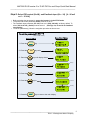
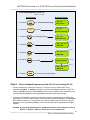
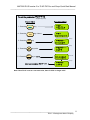
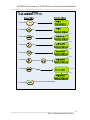
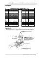
MA7200 PLUS Inverter 3 to 75 HP PID Fan and Pump Quick Start Manual
__________________________________________________________________
Appendix AEngineering Units Selected by P1-01=
Setting
Unit
0
Description
----
Setting
Unit
Description
13
MPM
meter / minute
1
%
%
14
CMM
meter3 / minute
2
PSI
PSI
15
W
W
3
GPH
gallon / hour
16
kW
kW
4
GPM
gallon / minute
17
°C
°C
5
InW
Inch water
18
m
meter
6
FPM
feet / minute
19
A
A
3
7
CFM
feet / minute
20
RPM
RPM
8
In
inch
21
SPM
stroke/minute
9
Ft
feet
22
/s
unit / s
10
HP
HP
23
/m
unit / m
11
°F
°F
24
/h
unit / h
12
m/s
meter / second
25
none
Appendix B Removing the LCD Digital Operator and Inverter Cover(s)
Remove the (2) screws
LCD Operator
RJ11 connector
Gently Lift
the
LCD Operator and remove the
connecting cable (RJ11) by
unplugging it from the back of
the LCD Operator.
Connecting cable
Gently remove the
cover(s).
________________________________________________________________ 22
TECO – Westinghouse Motor Company