1
2008 Residential Appendices
RA3-4
shall be made available to the enforcement agency, installing contractor, and HERS rater for use during the
installation work and for all applicable inspections.
RA3.1.4.1.2
Verifying the Duct System Installation
The location of all supply and return registers shall be verified from an inspection of the interior of the dwelling
unit. The location of the equipment and the size, R-value, and location of each duct segment shall be verified
by observation in the spaces where they are located. Deviations from the design shall not be allowed.
RA3.1.4.1.3
Verification for Ducts to be buried in Attic Insulation
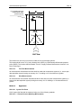
This procedure and the procedure of RA3.1.4.2 shall be carried out prior to covering the ducts with insulation.
Ducts to be buried shall be insulated to R4.2 or greater. In addition ducts designed to be in contact with the
ceiling shall be in continuous contact with the ceiling drywall or ceiling structure not more than 3.5 inches from
the ceiling drywall. A sign must be hung near the attic access reading “Caution: Buried Ducts. Markers indicate
location of buried ducts.” All ducts which will be completely buried shall have vertical markers which will be
visible after insulation installation at not more than every 8 feet of duct length and at the beginning and end of
each duct run.
RA3.1.4.2
System Fan Flow
For the purpose of establishing duct leakage criteria, the system fan flow shall be calculated using RA3.1.4.2.1,
RA3.1.4.2.2, or RA3.1.4.2.3.
RA3.1.4.2.1
Default System Fan Flow
Default system fan flow may be used only for homes where the duct system is being tested before the air
conditioning and heating system is installed and the equipment specification is not known. For heating only
systems the default fan flow shall be 0.5 CFM per ft2 of Conditioned Floor Area.
RA3.1.4.2.2
Nominal System Fan Flow
For heating only systems the fan flow shall be 21.7 CFM x Heating Capacity in thousands of Btu/hr. For
systems with cooling, the fan flow shall be 400 CFM per nominal ton of cooling capacity as specified by the
manufacturer or the heating only value, whichever is greater.
RA3.1.4.2.3
Measured System Fan Flow
The fan flow shall be as measured according to a procedure in Section RA3.3.3
RA3.1.4.3
Diagnostic Duct Leakage
Diagnostic duct leakage measurement is used by installers and raters to verify that total leakage meets the
criteria for any sealed duct system specified in the compliance documents. Diagnostic Duct Leakage from Fan
Pressurization of Ducts (Section RA3.1.4.3.1) is the only procedure that may be used by a HERS rater to verify
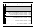
duct sealing in a new home. Table RA3.1-2 shows the leakage criteria and test procedures that may be used
to demonstrate compliance.
Appendix RA3 – Residential Field Verification and Diagnostic Test Protocols