1
MC55/56
Siemens Cellular Engine
Version:
DocID:
04.00a
MC55/56_hd_v04.00a
MC55/56_hd_v04.00a
Page 1 of 108
s
Hardware Interface Description
MC55/56 Hardware Interface Description
Confidential / Released
24.08.2006
MC55/56 Hardware Interface Description
Confidential / Released
s
Document Name:
MC55/56 Hardware Interface Description
Version:
04.00a
Date:
August 24, 2006
DocId:
MC55/56_hd_v04.00a
Status:
Confidential / Released
General Notes
Product is deemed accepted by Recipient and is provided without interface to Recipient’s products.
The documentation and/or Product are provided for testing, evaluation, integration and information
purposes. The documentation and/or Product are provided on an “as is” basis only and may contain
deficiencies or inadequacies. The Documentation and/or Product are provided without warranty of any
kind, express or implied. To the maximum extent permitted by applicable law, Siemens further
disclaims all warranties, including without limitation any implied warranties of merchantability,
completeness, fitness for a particular purpose and non-infringement of third-party rights. The entire risk
arising out of the use or performance of the Product and documentation remains with Recipient. This
Product is not intended for use in life support appliances, devices or systems where a malfunction of
the product can reasonably be expected to result in personal injury. Applications incorporating the
described product must be designed to be in accordance with the technical specifications provided in
these guidelines. Failure to comply with any of the required procedures can result in malfunctions or
serious discrepancies in results. Furthermore, all safety instructions regarding the use of mobile
technical systems, including GSM products, which also apply to cellular phones must be followed.
Siemens or its suppliers shall, regardless of any legal theory upon which the claim is based, not be
liable for any consequential, incidental, direct, indirect, punitive or other damages whatsoever
(including, without limitation, damages for loss of business profits, business interruption, loss of
business information or data, or other pecuniary loss) arising out the use of or inability to use the
Documentation and/or Product, even if Siemens has been advised of the possibility of such damages.
The foregoing limitations of liability shall not apply in case of mandatory liability, e.g. under the German
Product Liability Act, in case of intent, gross negligence, injury of life, body or health, or breach of a
condition which goes to the root of the contract. However, Claims for Damages arising from a breach
of a condition which goes to the root of the contract shall be limited to the foreseeable damage which is
intrinsic to the contract, unless caused by intent or gross negligence or based on liability for injury of
life, body or health. The above provision does not imply a change on the burden of proof to the
detriment of the Recipient. Subject to change without notice at any time. The interpretation of this
general note shall be governed and construed according to German law without reference to any other
substantive law.
Copyright
Copying of this document and giving it to others and the use or communication of the contents thereof,
are forbidden without express authority. Offenders are liable to the payment of damages. All rights
reserved in the event of grant of a patent or the registration of a utility model or design.
Copyright © Siemens AG 2006
MC55/56_hd_v04.00a
Page 2 of 108
24.08.2006
MC55/56 Hardware Interface Description
Confidential / Released
s
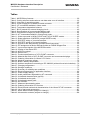
Contents
0
Document history....................................................................................................... 7
1
Introduction ...............................................................................................................11
1.1 Related documents ............................................................................................11
1.2 Terms and abbreviations....................................................................................12
1.3 Type approval ....................................................................................................15
1.4 Safety precautions .............................................................................................17
2
Product concept........................................................................................................19
2.1 MC55/56 key features at a glance......................................................................20
2.2 Circuit concept ...................................................................................................23
3
Application Interface.................................................................................................24
3.1 Operating modes ...............................................................................................25
3.2 Power supply .....................................................................................................27
3.2.1
Power supply pins on the board-to-board connector.............................27
3.2.2
Minimizing power losses.......................................................................28
3.2.3
Monitoring power supply.......................................................................28
3.3 Power up / down scenarios ................................................................................29
3.3.1
Turn on MC55/56 .................................................................................29
3.3.1.1 Turn on MC55/56 using the ignition line /IGT (Power on) .....................30
3.3.1.2 Timing of the ignition process...............................................................31
3.3.1.3 Turn on MC55/56 using the POWER signal .........................................32
3.3.1.4 Turn on MC55/56 using the RTC (Alarm mode) ...................................32
3.3.2
Turn off MC55/56 .................................................................................34
3.3.2.1 Turn off MC55/56 using AT command..................................................34
3.3.2.2 Emergency shutdown using /EMERGOFF pin ......................................35
3.3.3
Automatic shutdown .............................................................................36
3.3.3.1 Thermal shutdown ................................................................................36
3.3.3.2 Temperature control during emergency call .........................................37
3.3.3.3 Undervoltage shutdown if battery NTC is present.................................37
3.3.3.4 Undervoltage shutdown if no battery NTC is present............................38
3.3.3.5 Overvoltage shutdown..........................................................................38
3.4 Automatic GPRS Multislot Class change............................................................39
3.5 Charging control.................................................................................................40
3.5.1
Battery pack characteristics..................................................................41
3.5.2
Implemented charging technique..........................................................43
3.5.3
Operating modes during charging ........................................................44
3.5.4
Charger requirements ..........................................................................45
3.6 Power saving .....................................................................................................46
3.6.1
No power saving (AT+CFUN=1) ...........................................................46
3.6.2
NON-CYCLIC SLEEP mode (AT+CFUN=0) .........................................46
3.6.3
CYCLIC SLEEP mode (AT+CFUN=5, 6, 7, 8) ......................................47
3.6.4
CYCLIC SLEEP mode AT+CFUN=9 ....................................................47
3.6.5
Timing of the /CTS signal in CYCLIC SLEEP modes ...........................47
3.6.6
Wake up MC55/56 from SLEEP mode .................................................49
3.6.6.1 Wake-up via /RTS0 and RTS1 (if AT+CFUN=0 or AT+CFUN=9) .........50
3.7 Summary of state transitions (except SLEEP mode)..........................................51
3.8 RTC backup .......................................................................................................52
3.9 Serial interfaces .................................................................................................53
3.9.1
Features supported on first and second serial interface .......................54
MC55/56_hd_v04.00a
Page 3 of 108
24.08.2006
MC55/56 Hardware Interface Description
Confidential / Released
s
3.10 Audio interfaces .................................................................................................56
3.10.1 Microphone circuit ................................................................................57
3.10.2 Speech processing ...............................................................................58
3.10.3 DAI timing.............................................................................................58
3.11 SIM interface......................................................................................................60
3.11.1 Requirements for using the CCIN pin ...................................................61
3.11.2 Design considerations for SIM card holder ...........................................62
3.12 Control signals ...................................................................................................63
3.12.1 Inputs ...................................................................................................63
3.12.2 Outputs.................................................................................................64
3.12.2.1 Synchronization signal..........................................................................64
3.12.2.2 Using the SYNC pin to control a status LED.........................................65
3.12.2.3 Behavior of the /RING0 line (ASC0 interface only) ...............................67
4
Antenna interface ......................................................................................................68
4.1 Antenna installation............................................................................................68
4.1.1
Antenna pad .........................................................................................70
4.1.1.1 Suitable cable types .............................................................................70
4.1.2
Hirose antenna connector ....................................................................71
5
Electrical, reliability and radio characteristics .......................................................75
5.1 Absolute maximum ratings .................................................................................75
5.2 Operating temperatures .....................................................................................76
5.3 Storage conditions .............................................................................................77
5.4 Reliability characteristics ....................................................................................78
5.5 Electrical specifications of the application interface............................................79
5.6 Power supply ratings..........................................................................................84
5.6.1
Current consumption during transmit burst...........................................85
5.7 Electrical characteristics of the voiceband part...................................................90
5.7.1
Setting audio parameters by AT commands.........................................90
5.7.2
Audio programming model ...................................................................91
5.7.3
Characteristics of audio modes ............................................................92
5.7.4
Voiceband receive path ........................................................................93
5.7.5
Voiceband transmit path.......................................................................94
5.8 Air interface........................................................................................................95
5.9 Electrostatic discharge .......................................................................................96
6
Mechanics..................................................................................................................97
6.1 Mechanical dimensions of MC55/56...................................................................97
6.2 Mounting MC55/56 onto the application platform ...............................................99
6.3 Board-to-board connector ................................................................................100
6.3.1
Mechanical dimensions of the Hirose DF12 connector .......................101
6.3.2
Adapter cabling ..................................................................................101
7
Reference Approval ................................................................................................102
7.1 Reference Equipment for Type Approval .........................................................102
7.2 Compliance with FCC Rules and Regulations (MC55 only)..............................103
7.3 Compliance with FCC Rules and Regulations (MC56 only)..............................104
8
Design example.......................................................................................................105
9
List of parts and accessories .................................................................................107
MC55/56_hd_v04.00a
Page 4 of 108
24.08.2006
MC55/56 Hardware Interface Description
Confidential / Released
s
Figures
Figure 1: MC55/56 block diagram ........................................................................................23
Figure 2: Power supply limits during transmit burst ..............................................................28
Figure 3: Power-on by ignition signal....................................................................................30
Figure 4: Timing of power-on process if VDDLP is not used ................................................31
Figure 5: Timing of power-on process if VDDLP is fed from external source........................32
Figure 6: Deactivating GSM engine by /EMERGOFF signal.................................................35
Figure 7: Schematic of approved charging transistor, trickle charging and ESD protection..40
Figure 8: Battery pack circuit diagram ..................................................................................41
Figure 9: Charging process ..................................................................................................43
Figure 10: Timing of /CTS signal (example for a 2.12 s paging cycle)..................................48
Figure 11: Beginning of power saving if CFUN=5 or 7..........................................................48
Figure 12: RTC supply from capacitor ..................................................................................52
Figure 13: RTC supply from rechargeable battery................................................................52
Figure 14: RTC supply from non-chargeable battery............................................................52
Figure 15: Serial interfaces ..................................................................................................53
Figure 16: Audio block diagram............................................................................................56
Figure 17: Schematic of microphone inputs .........................................................................57
Figure 18: DAI timing on transmit path .................................................................................59
Figure 19: DAI timing on receive path ..................................................................................59
Figure 20: SIM card holder of DSB45 Support Box ..............................................................62
Figure 21: Pin numbers of Molex SIM card holder on DSB45 Support Box ..........................62
Figure 22: SYNC signal during transmit burst ......................................................................64
Figure 23: LED Circuit (Example) .........................................................................................66
Figure 24: Incoming voice call ..............................................................................................67
Figure 25: URC transmission ...............................................................................................67
Figure 26: U.FL-R-SMT connector .......................................................................................68
Figure 27: Antenna pad and GND plane ..............................................................................68
Figure 28: Never use antenna connector and antenna pad at the same time.......................69
Figure 29: Restricted area around antenna pad ...................................................................69
Figure 30: Mechanical dimensions of U.FL-R-SMT connector..............................................71
Figure 31: U.FL-R-SMT connector with U.FL-LP-040 plug ...................................................72
Figure 32: U.FL-R-SMT connector with U.FL-LP-066 plug ...................................................72
Figure 33: Specifications of U.FL-LP-(V)-040(01) plug .........................................................73
Figure 34: Pin assignment (top view on MC55/56) ...............................................................79
Figure 35: Typical current consumption vs. PCL in EGSM 900 network ...............................85
Figure 36: Typical current consumption vs. PCL in GSM 1800 network ...............................86
Figure 37: Typical current consumption PCL in GSM 1900 network.....................................86
Figure 38: Peak current consumption during transmit burst vs. PCL in EGSM 900 network.87
Figure 39: Peak current consumption during transmit burst vs. PCL in GSM 1800 network .87
Figure 40: Peak current consumption during transmit burst PCL in GSM 1900 network.......88
Figure 41: Typical current consumption vs. return loss.........................................................89
Figure 42: Audio programming model ..................................................................................91
Figure 43: MC55/56 – top view.............................................................................................97
Figure 44: MC55/56 bottom view..........................................................................................97
Figure 45: Mechanical dimensions of MC55/56 ....................................................................98
Figure 46: Hirose DF12C receptacle on MC55/56 ..............................................................100
Figure 47: Header Hirose DF12 series ...............................................................................100
Figure 48: Mechanical dimensions of Hirose DF12 connector ............................................101
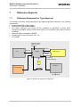
Figure 49: Reference equipment for approval ....................................................................102
Figure 50: Schematic diagram of MC55/56 sample application ..........................................106
MC55/56_hd_v04.00a
Page 5 of 108
24.08.2006
MC55/56 Hardware Interface Description
Confidential / Released
s
Tables
Table 1: MC55/56 key features ............................................................................................20
Table 2: Coding schemes and maximum net data rates over air interface ...........................22
Table 3: Overview of operating modes .................................................................................25
Table 4: Power supply pins of board-to-board connector .....................................................27
Table 5: AT commands available in Alarm mode .................................................................33
Table 6: Temperature dependent behavior ..........................................................................37
Table 7: Bill of material for external charging circuit .............................................................40
Table 8: Specifications of recommended battery pack .........................................................42
Table 9: Comparison Charge-only and Charge mode ..........................................................44
Table 10: AT commands available in Charge-only mode......................................................45
Table 11: Wake-up events in NON-CYCLIC and CYCLIC SLEEP modes............................49
Table 12: State transitions of MC55/56 (except SLEEP mode) ............................................51
Table 13: DCE-DTE wiring of 1st serial interface .................................................................54
Table 14: DCE-DTE wiring of 2nd serial interface ................................................................55
Table 15: Signals of the SIM interface (board-to-board connector) ......................................60
Table 16: Pin assignment of Molex SIM card holder on DSB45 Support Box .......................62
Table 17: Input control signals of the MC55/56 module........................................................63
Table 18: Coding of the status LED......................................................................................65
Table 19: ASC0 ring signal...................................................................................................67
Table 20: Return loss ...........................................................................................................68
Table 21: Product specifications of U.FL-R-SMT connector .................................................71
Table 22: Material and finish of U.FL-R-SMT connector and recommended plugs...............72
Table 23: Ordering information for Hirose U.FL Series.........................................................74
Table 24: Absolute maximum ratings ...................................................................................75
Table 25: Board / battery temperature..................................................................................76
Table 26: Ambient temperature according to IEC 60068-2 (without forced air circulation)....76
Table 27: Charging temperature...........................................................................................76
Table 28: Storage conditions................................................................................................77
Table 29: Summary of reliability test conditions....................................................................78
Table 30: Electrical description of application interface ........................................................80
Table 31: Power supply ratings ............................................................................................84
Table 32: Audio parameters adjustable by AT command .....................................................90
Table 33: Voiceband characteristics (typical) .......................................................................92
Table 34: Voiceband receive path ........................................................................................93
Table 35: Voiceband transmit path.......................................................................................94
Table 36: Air Interface..........................................................................................................95
Table 37: Measured electrostatic values ..............................................................................96
Table 38: Ordering information DF12 series.......................................................................100
Table 39: Electrical and mechanical characteristics of the Hirose DF12C connector..........100
Table 40: List of parts and accessories ..............................................................................107
Table 41: Molex sales contacts (subject to change) ...........................................................108
Table 42: Hirose sales contacts (subject to change) ..........................................................108
MC55/56_hd_v04.00a
Page 6 of 108
24.08.2006
MC55/56 Hardware Interface Description
Confidential / Released
0
s
Document history
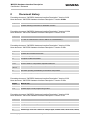
Preceding document: "MC55/56 Hardware Interface Description" Version 04.00
New document: "MC55/56 Hardware Interface Description" Version 04.00a
Chapter
What is new
9
Updated ordering information for MC55/56 modules.
Preceding document: "MC55/56 Hardware Interface Description" Version 03.03b
New document: "MC55/56 Hardware Interface Description" Version 04.00
Chapter
What is new
3.3.1.1
Added remark on idle timeout after ignition and before sending the first AT command
(in case no hardware flow control or URCs are used/available).
Preceding document: "MC55/56 Hardware Interface Description" Version 03.03a
New document: "MC55/56 Hardware Interface Description" Version 03.03b
Chapter
What is new
1.1
Updated list of related documents.
1.3
Added CE logo. Updated version number of standard “NAPRD.03”.
1.3
Compliance statement added.
2.1
Added specification IEC 60068-2. Added automatic thermal shutdown. Added TCP/IP.
3.3.3.1
Revised Table 6: Temperature dependent behavior.
3.12.2.1,
3.12.2.2
Some text changes related to SYNC pin and LED patterns.
5.2
Specified operating board/battery and ambient temperature.
5.3
Changed storage air temperature.
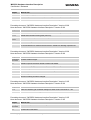
Preceding document: "MC55/56 Hardware Interface Description" Version 03.03
New document: "MC55/56 Hardware Interface Description" Version 03.03a
Chapter
What is new
1.3
Updated version numbers of several standards.
5.7.2
Updated figure “Audio programming model”.
Preceding document: "MC55/56 Hardware Interface Description" Version 02.90
New document: "MC55/56 Hardware Interface Description" Version 03.03
Chapter
What is new
1.3
Deleted WEEE Directives. Added RoHS logo.
3.5
Changed a resistor in Figure 7.
5.3
New chapter: Storage conditions
5.6
Modified typ. and max. values for voltage ripple, SLEEP mode, IDLE mode, GPRS
MC55/56_hd_v04.00a
Page 7 of 108
24.08.2006
MC55/56 Hardware Interface Description
Confidential / Released
Chapter
s
What is new
over 2Tx, peak supply current
5.5
Corrected specification of VDDLP (RTC backup) and CCIO (SIM interface).
8
Added remark on distance from SIM to antenna and microphone.
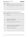
Preceding document: "MC55/56 Hardware Interface Description" Version 02.90
New document: "MC55/56 Hardware Interface Description" Version 02.96
Chapter
What is new
1.3
Deleted section “Compliance with international rules and regulations”.
3.3.1.1
Added further details of timing after power-up.
3.6.2, 3.6.6,
3.6.6.1
More detailed description of RTS wake-up.
3.12.2.2
Some text changes related to LED behavior in CYCLIC SLEEP mode.
7.2, 7.3
Deleted note on extra FCC certification for OEM products. Changed note on
recommendations for mobile and fixed devices. Added FCC labeling requirements.
Preceding document: "MC55/56 Hardware Interface Description" Version 02.06
New document: "MC55/56 Hardware Interface Description" Version 02.90
Chapter
What is new
Throughout
document
Updated module images.
1.3
Added European Directives related to RoHS and WEEE.
3.5.2
Described charging procedure if battery was deeply discharged.
3.12.2.3
Same description of RING line behavior for voice, data, fax.
6.2
Deleted screw and washer restrictions for mounting holes of MC55/56.
6.1
Updated figure “Mechanical dimensions of MC55/56”
9
Siemens ordering numbers changed.
Preceding document: "MC55/56 Hardware Interface Description" Version 01.95
New document: "MC55/56 Hardware Interface Description" Version 02.06
Chapter
What is new
5.7.3
Table 33: Sidetone gain at default settings for audio mode 5 and 6 set to -∞ dB
9
Added new Siemens ordering numbers
Preceding document: "MC55/56 Hardware Interface Description" Version 01.05
New document: "MC55/56 Hardware Interface Description" Version 01.95
Chapter
What is new
Throughout
document
Maximum temperature has been changed from +65°C to +70°C.
1.3
Updated list of standards.
MC55/56_hd_v04.00a
Page 8 of 108
24.08.2006
MC55/56 Hardware Interface Description
Confidential / Released
Chapter
s
What is new
3.6, 3.12.2.2 More detailed description of status LED patterns.
3.5.1
Deleted vendor XWODA, battery pack can be obtained from various dealers.
3.11
Use CCGND line to shield CCIO line from CCCLK line.
5.2
Added footnote regarding heat sink.
5.6
Typical value for supply voltage has been changed from 4.1V to 4.2V
7.2, 7.3
Added IC: 267W-MC55 and IC: IC: 267W-MC56
8
New chapter: Design example
----
Deleted chapter “Maximum number of turn-on / turn-off cycles”
Preceding document: "MC55/56 Hardware Interface Description" Version 01.03a
New document: "MC55/56 Hardware Interface Description" Version 01.05
Chapter
What is new
1.3
Updated list of standards, MC55/56 now fully type approved and labeled with CE mark
2.2
New block diagram.
3.2.2, 5.5
All statements relating to typical peak current now 1.6 A.
3.2.3
More detailed description of measuring periods for BATT+.
3.1, 3.5.3
Removed remarks about charging during Alarm mode
3.3.1.4
Battery can be charged while module is in Alarm mode.
3.3.2.1
To keep /EMERGOFF pin and output pins of the serial interfaces from floating when in
high impedance state use additional resistors.
3.3.3.5
Modified description of overvoltage conditions.
3.5
Improved Figure 7.
3.6
Added SLEEP mode 9, added information on RTS, revised Table 11.
3.12.2.3
Advantages of the /RING0 line usage explained in more detail.
4.1
Marked antenna pad and ground pad.
4.1.2
Rated frequency changed from 3 to 6 GHz
5.5
Table 30 - /EMERGOFF pin and output pins of serial interface: To keep output pins
from floating when in high impedance state use additional resistors.
5.6
Added test conditions for TALK and DATA GPRS: 50 Ω
5.6.1
Revised introduction.
5.7.2
Improved Figure 42: Audio programming model
6.1
New drawing in Figure 45. Corrected height from 2.8 ±0.2 to 2.95 ±0.2 mm
6.2
Revised mounting instructions.
9
Siemens ordering numbers added.
---
Deleted chapter on cooling elements.
MC55/56_hd_v04.00a
Page 9 of 108
24.08.2006
MC55/56 Hardware Interface Description
Confidential / Released
s
Preceding document: "MC55/56 Hardware Interface Description" Version 01.03
New document: "MC55/56 Hardware Interface Description" Version 01.03a
Chapter
What is new
7.2, 7.3
Corrected MC55 and MC56 specific information on FFC compliance
Preceding document: "MC55/56 Hardware Interface Description" Version 01.02
New document: "MC55/56 Hardware Interface Description" Version 01.03
Chapter
What is new
1.3
Note on necessary FCC certification added.
MC55/56_hd_v04.00a
Page 10 of 108
24.08.2006
MC55/56 Hardware Interface Description
Confidential / Released
1
s
Introduction
This document describes the hardware interface of the Siemens MC55/56 module that
connects to the cellular device application and the air interface. As MC55/56 is intended to
integrate with a wide range of application platforms, all functional components are described
in great detail.
This guide therefore covers all information needed to design and set up cellular applications
incorporating the MC55/56 module. It aids rapid retrieval of interface specifications, electrical
and mechanical details and information on the requirements to be considered for integration
of further components.
1.1
[1]
[2]
[3]
[4]
[5]
[6]
[7]
[8]
[9]
[10]
[11]
[12]
[13]
[14]
[15]
Related documents
MC55 AT Command Set
MC56 AT Command Set
MC55/56 Release Notes
GPRS Startup User's Guide
Remote-SAT User's Guide
DSB45 Support Box - Evaluation Kit for Siemens Cellular Engines
Application Note 23: Installing MC55/56 on DSB45
Application Note 07: Li-Ion Batteries in GSM Applications
Application Note 16: Upgrading MC5x Firmware, Version 06
Application Note 02: Audio Interface Design
Multiplexer User's Guide
Multiplex Driver Developer’s Guide for Windows 2000 and Windows XP
Multiplex Driver Installation Guide for Windows 2000 and Windows XP
Application Note 22: Using TTY / CTM equipment
Application Note 24: Application Developer’s Guide
Application Note 28: Customer SIM Lock
Prior to using the MC55/56 engines or upgrading to a new firmware release, please carefully
read the latest product information.
For further information visit the Siemens Website:
http://www.siemens.com/wm
MC55/56_hd_v04.00a
Page 11 of 108
24.08.2006
MC55/56 Hardware Interface Description
Confidential / Released
1.2
s
Terms and abbreviations
Abbreviation
Description
ADC
Analog-to-Digital Converter
AFC
Automatic Frequency Control
AGC
Automatic Gain Control
ANSI
American National Standards Institute
ARFCN
Absolute Radio Frequency Channel Number
ARP
Antenna Reference Point
ASC0 / ASC1
Asynchronous Serial Controller. Abbreviations used for first and second serial
interface of MC55/56
ASIC
Application Specific Integrated Circuit
B
Thermistor Constant
B2B
Board-to-board connector
BER
Bit Error Rate
BTS
Base Transceiver Station
CB or CBM
Cell Broadcast Message
CE
Conformité Européene (European Conformity)
CHAP
Challenge Handshake Authentication Protocol
CPU
Central Processing Unit
CS
Coding Scheme
CSD
Circuit Switched Data
CTS
Clear to Send
DAC
Digital-to-Analog Converter
DAI
Digital Audio Interface
dBm0
Digital level, 3.14dBm0 corresponds to full scale, see ITU G.711, A-law
DCE
Data Communication Equipment (typically modems, e.g. Siemens GSM engine)
DCS 1800
Digital Cellular System, also referred to as PCN
DRX
Discontinuous Reception
DSB
Development Support Box
DSP
Digital Signal Processor
DSR
Data Set Ready
DTE
Data Terminal Equipment (typically computer, terminal, printer or, for example, GSM
application)
DTR
Data Terminal Ready
DTX
Discontinuous Transmission
EFR
Enhanced Full Rate
EGSM
Enhanced GSM
MC55/56_hd_v04.00a
Page 12 of 108
24.08.2006
MC55/56 Hardware Interface Description
Confidential / Released
s
Abbreviation
Description
EMC
Electromagnetic Compatibility
ESD
Electrostatic Discharge
ETS
European Telecommunication Standard
FCC
Federal Communications Commission (U.S.)
FDMA
Frequency Division Multiple Access
FR
Full Rate
GMSK
Gaussian Minimum Shift Keying
GPRS
General Packet Radio Service
GSM
Global Standard for Mobile Communications
HiZ
High Impedance
HR
Half Rate
I/O
Input/Output
IC
Integrated Circuit
IMEI
International Mobile Equipment Identity
ISO
International Standards Organization
ITU
International Telecommunications Union
kbps
kbits per second
LED
Light Emitting Diode
Li-Ion
Lithium-Ion
Mbps
Mbits per second
MMI
Man Machine Interface
MO
Mobile Originated
MS
Mobile Station (GSM engine), also referred to as TE
MSISDN
Mobile Station International ISDN number
MT
Mobile Terminated
NTC
Negative Temperature Coefficient
OEM
Original Equipment Manufacturer
PA
Power Amplifier
PAP
Password Authentication Protocol
PBCCH
Packet Switched Broadcast Control Channel
PCB
Printed Circuit Board
PCL
Power Control Level
PCM
Pulse Code Modulation
PCN
Personal Communications Network, also referred to as DCS 1800
PCS
Personal Communication System, also referred to as GSM 1900
PDU
Protocol Data Unit
PLL
Phase Locked Loop
MC55/56_hd_v04.00a
Page 13 of 108
24.08.2006
MC55/56 Hardware Interface Description
Confidential / Released
Abbreviation
Description
PPP
Point-to-point protocol
PSU
Power Supply Unit
R&TTE
Radio and Telecommunication Terminal Equipment
RAM
Random Access Memory
RF
Radio Frequency
RMS
Root Mean Square (value)
ROM
Read-only Memory
RTC
Real Time Clock
Rx
Receive Direction
SAR
Specific Absorption Rate
SELV
Safety Extra Low Voltage
SIM
Subscriber Identification Module
SMS
Short Message Service
SRAM
Static Random Access Memory
TA
Terminal adapter (e.g. GSM engine)
TDMA
Time Division Multiple Access
TE
Terminal Equipment, also referred to as DTE
Tx
Transmit Direction
UART
Universal asynchronous receiver-transmitter
URC
Unsolicited Result Code
USSD
Unstructured Supplementary Service Data
VSWR
Voltage Standing Wave Ratio
s
Phonebook abbreviations
FD
SIM fixdialing phonebook
LD
SIM last dialling phonebook (list of numbers most recently dialled)
MC
Mobile Equipment list of unanswered MT calls (missed calls)
ME
Mobile Equipment phonebook
ON
Own numbers (MSISDNs) stored on SIM or ME
RC
Mobile Equipment list of received calls
SM
SIM phonebook
MC55/56_hd_v04.00a
Page 14 of 108
24.08.2006
MC55/56 Hardware Interface Description
Confidential / Released
1.3
s
Type approval
MC55/56 has been approved to comply with the directives and standards listed below.
European directives
99/05/EC
“Directive of the European Parliament and of the Council of 9 March
1999 on radio equipment and telecommunications terminal
equipment and the mutual recognition of their conformity”, in short
referred to as R&TTE Directive 1999/5/EC
The product is labeled with the CE conformity mark
89/336/EC
Directive on electromagnetic compatibility
73/23/EC
Directive on electrical equipment designed for use within certain
voltage limits (Low Voltage Directive)
2002/95/EC
Directive of the European Parliament and of the
Council of 27 January 2003 on the restriction of the use
of certain hazardous substances in electrical and
electronic equipment (RoHS)
Standards of North American Type Approval
CFR Title 47
“Code of Federal Regulations, Part 22 and Part 24
(Telecommunications, PCS)”; US Equipment Authorization FCC
UL 60 950
“Product Safety Certification” (Safety requirements)
NAPRD.03
“Overview of PCS Type certification review board
Mobile Equipment Type Certification and IMEI control”
PCS Type Certification Review board (PTCRB), Version 3.4.1
RSS133 (Issue2)
Canadian Standard
Standards of European Type Approval
3GPP TS 51.010-1
“Digital cellular telecommunications system (Phase 2); Mobile Station
(MS) conformance specification”
EN 301 511
“V9.0.2 Global System for Mobile communications (GSM); Harmonized
standard for mobile stations in the GSM 900 and DCS 1800 bands
covering essential requirements under article 3.2 of the R&TTE
directive (1999/5/EC)
GCF-CC
“Global Certification Forum - Certification Criteria” V3.18.0
EN 301 489-1
“V1.4.1 Candidate Harmonized European Standard (Telecommunications series) Electro Magnetic Compatibility and Radio
spectrum Matters (ERM); Electro Magnetic Compatibility (EMC) standard for radio equipment and services; Part 1: Common Technical
Requirements”
MC55/56_hd_v04.00a
Page 15 of 108
24.08.2006
MC55/56 Hardware Interface Description
Confidential / Released
s
EN 301 489-07
“V1.2.1 Electro Magnetic Compatibility and Radio spectrum Matters
(ERM); Electro Magnetic Compatibility (EMC) standard for radio
equipment and services; Part 7: Specific conditions for mobile and
portable radio and ancillary equipment of digital cellular radio telecommunications systems (GSM and DCS)”
EN 60 950
Safety of information technology equipment (2000)
Requirements of quality
IEC 60068
DIN EN 60529
Environmental testing
IP codes
Compliance with international rules and regulations
Manufacturers of mobile or fixed devices incorporating MC55/56 modules are advised to
have their completed product tested and approved for compliance with all applicable national
and international regulations. As a tri-band GSM/GPRS engine designed for use on any
GSM network in the world, MC55/56 is required to pass all approvals relevant to operation
on the European and North American markets. For the North American market this includes
the Rules and Regulations of the Federal Communications Commission (FCC) and PTCRB,
for the European market the R&TTE Directives must be fully satisfied (see also chapters 7.2.
and 7.3).
SAR requirements specific to handheld mobiles
Mobile phones, PDAs or other handheld transmitters and receivers incorporating a GSM
module must be in accordance with the guidelines for human exposure to radio frequency
energy. This requires the Specific Absorption Rate (SAR) of handheld MC55/56 based
applications to be evaluated and approved for compliance with national and/or international
regulations.
Since the SAR value varies significantly with the individual product design manufacturers are
advised to submit their product for approval if designed for handheld operation. For
European and US markets the relevant directives are mentioned below. It is the
responsibility of the manufacturer of the final product to verify whether or not further
standards, recommendations or directives are in force outside these areas.
Products intended for sale on US markets
ES 59005/ANSI C95.1 Considerations for evaluation of human exposure to Electromagnetic
Fields (EMFs) from Mobile Telecommunication Equipment (MTE) in
the frequency range 30MHz - 6GHz
Products intended for sale on European markets
EN 50360
Product standard to demonstrate the compliance of mobile phones
with the basic restrictions related to human exposure to
electromagnetic fields (300MHz - 3GHz)
MC55/56_hd_v04.00a
Page 16 of 108
24.08.2006
MC55/56 Hardware Interface Description
Confidential / Released
1.4
s
Safety precautions
The following safety precautions must be observed during all phases of the operation,
usage, service or repair of any cellular terminal or mobile incorporating MC55/56.
Manufacturers of the cellular terminal are advised to convey the following safety information
to users and operating personnel and to incorporate these guidelines into all manuals
supplied with the product. Failure to comply with these precautions violates safety standards
of design, manufacture and intended use of the product. Siemens AG assumes no liability
for customer failure to comply with these precautions.
When in a hospital or other health care facility, observe the restrictions on the
use of mobiles. Switch the cellular terminal or mobile off, if instructed to do so
by the guidelines posted in sensitive areas. Medical equipment may be
sensitive to RF energy.
The operation of cardiac pacemakers, other implanted medical equipment
and hearing aids can be affected by interference from cellular terminals or
mobiles placed close to the device. If in doubt about potential danger, contact
the physician or the manufacturer of the device to verify that the equipment is
properly shielded. Pacemaker patients are advised to keep their hand-held
mobile away from the pacemaker, while it is on.
Switch off the cellular terminal or mobile before boarding an aircraft. Make
sure it cannot be switched on inadvertently. The operation of wireless
appliances in an aircraft is forbidden to prevent interference with
communications systems. Failure to observe these instructions may lead to
the suspension or denial of cellular services to the offender, legal action, or
both.
Do not operate the cellular terminal or mobile in the presence of flammable
gases or fumes. Switch off the cellular terminal when you are near petrol
stations, fuel depots, chemical plants or where blasting operations are in
progress. Operation of any electrical equipment in potentially explosive
atmospheres can constitute a safety hazard.
Your cellular terminal or mobile receives and transmits radio frequency
energy while switched on. Remember that interference can occur if it is used
close to TV sets, radios, computers or inadequately shielded equipment.
Follow any special regulations and always switch off the cellular terminal or
mobile wherever forbidden, or when you suspect that it may cause
interference or danger.
Road safety comes first! Do not use a hand-held cellular terminal or mobile
when driving a vehicle, unless it is securely mounted in a holder for handsfree
operation. Before making a call with a hand-held terminal or mobile, park the
vehicle.
Handsfree devices must be installed by qualified personnel. Faulty installation
or operation can constitute a safety hazard.
MC55/56_hd_v04.00a
Page 17 of 108
24.08.2006
MC55/56 Hardware Interface Description
Confidential / Released
SOS
s
IMPORTANT!
Cellular terminals or mobiles operate using radio signals and cellular
networks. Because of this, connection cannot be guaranteed at all times
under all conditions. Therefore, you should never rely solely upon any
wireless device for essential communications, for example emergency calls.
Remember, in order to make or receive calls, the cellular terminal or mobile
must be switched on and in a service area with adequate cellular signal
strength.
Some networks do not allow for emergency calls if certain network services
or phone features are in use (e.g. lock functions, fixed dialling etc.). You may
need to deactivate those features before you can make an emergency call.
Some networks require that a valid SIM card be properly inserted in the
cellular terminal or mobile.
MC55/56_hd_v04.00a
Page 18 of 108
24.08.2006
MC55/56 Hardware Interface Description
Confidential / Released
2
s
Product concept
Designed for use on any GSM network in the world, Siemens MC55 is a tri-band GSM/GPRS
engine that works on the three frequencies GSM 900 MHz, GSM 1800 MHz and GSM
1900 MHz. MC56 is a tri-band GSM/GPRS engine that works on the three frequencies GSM
850MHz, GSM 1800 MHz and GSM 1900 MHz. MC55/56 features GPRS multislot class 10
and supports the GPRS coding schemes CS-1, CS-2, CS-3 and CS-4.
To save space on the application platform, MC55/56 comes as an extremely slim and
compact module. This makes it ideally suited for a broad range of mobile computing devices,
and particularly offers easy integration with smart phones, PDAs, and other handhelds.
The tiny MC55/56 module incorporates all you need to create high-performance GSM/GPRS
solutions: baseband processor, power supply ASIC, complete radio frequency circuit
including a power amplifier and antenna interface. The power amplifier is directly fed from
the supply voltage BATT+. A compact “stacked FLASH / SRAM” device stores the MC55/56
software in the flash memory section, and static RAM section provides the additional storage
capacity required by GPRS connectivity.
The physical interface to the cellular application is made through a board-to-board
connector. It consists of 50 pins, required for controlling the unit, transferring data and audio
signals and providing power supply lines.
MC55/56 comprises two serial interfaces (ASC0 and ASC1) giving you maximum flexibility
for easy integration with the Man-Machine Interface (MMI).
An extremely versatile audio concept offers various audio interfaces, each available on the
board-to-board connector: a digital audio interface (DAI) and two analog audio interfaces.
Using AT commands you can easily switch back and forth and select different audio modes.
The external dual-band or triple-band antenna can be connected optionally to a connector on
the top side or to a pad on the bottom side.
The power saving technique minimizes current consumption to as low as 3mA. In SLEEP
mode, MC55/56 is able to wake up on demand and to resume power saving automatically if
no activity is required.
For battery powered applications, MC55/56 features a charging control which can be used to
charge a Li-Ion battery. The charging circuit must be implemented outside the module on the
application platform.
MC55/56_hd_v04.00a
Page 19 of 108
24.08.2006
s
MC55/56 Hardware Interface Description
Confidential / Released
2.1
MC55/56 key features at a glance
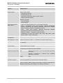
Table 1: MC55/56 key features
Feature
Implementation
Power supply
Single supply voltage 3.3V – 4.8V
Power saving
Minimizes power consumption in SLEEP mode to 3mA
Charging
Supports charging control for Li-Ion battery
Frequency bands
• MC55 Tri-band: EGSM 900, GSM 1800, GSM 1900
• MC56 Tri-band: GSM 850, GSM 1800, GSM 1900
• Compliant to GSM Phase 2/2+
GSM class
Small MS
Transmit power
• Class 4 (2W) at EGSM 900 and GSM 850
• Class 1 (1W) at GSM 1800 and GSM 1900
GPRS connectivity
• GPRS multi-slot class 10
• GPRS mobile station class B
Ambient operating
temperature according
to IEC 60068-2
• Normal operation:
Humidity
max. 90 % relative humidity
DATA
• Restricted operation:
-20°C to +55°C
-25°C to -20°C and +55°C to +70°C
• Automatic thermal shutdown:
≤-25°C and ≥+70°C
When an emergency call is in progress automatic temperature shutdown
is deferred.
GPRS: • GPRS data downlink transfer: max. 85.6 kbps (see Table 2)
• GPRS data uplink transfer: max. 42.8 kbps (see Table 2)
• Coding scheme: CS-1, CS-2, CS-3 and CS-4
• MC55/56 supports the two protocols PAP (Password Authentication
Protocol) and CHAP (Challenge Handshake Authentication Protocol)
commonly used for PPP connections.
• Support of Packet Switched Broadcast Control Channel (PBCCH) allows
you to benefit from enhanced GPRS performance when offered by the
network operators.
CSD:
• CSD transmission rates: 2.4, 4.8, 9.6, 14.4 kbps, non-transparent, V.110
• Unstructured Supplementary Services Data (USSD) support
SMS
• MT, MO, CB, Text and PDU mode
• SMS storage: SIM card plus 25 SMS locations in the mobile equipment
• Transmission of SMS alternatively over CSD or GPRS. Preferred mode
can be user-defined.
TCP/IP stack
Internet services: TCP, UDP, HTTP, FTP, SMTP, POP3
Access by AT commands
FAX
Group 3: Class 1, Class 2
SIM interface
• Supported SIM card: 3V
• External SIM card reader has to be connected via interface connector
(note that card reader is not part of MC55/56)
External antenna
MC55/56_hd_v04.00a
Connected via 50 Ohm antenna connector or antenna pad
Page 20 of 108
24.08.2006
s
MC55/56 Hardware Interface Description
Confidential / Released
Feature
Implementation
Audio interfaces
Two analog audio interfaces, one digital audio interface (DAI)
Audio features
Speech codec modes:
• Half Rate (ETS 06.20)
• Full Rate (ETS 06.10)
• Enhanced Full Rate (ETS 06.50 / 06.60 / 06.80)
• Adaptive Multi Rate (AMR)
Handsfree operation
• Echo cancellation
• Noise reduction
Two serial interfaces:
ASC0, ASC1
• 2.65V level, bi-directional bus for AT commands and data
• ASC0 – full-featured 8-wire serial interface. Supports RTS0/CTS0
hardware handshake and software XON/XOFF flow control. Multiplex
ability according to GSM 07.10 Multiplexer Protocol.
• ASC1 - 4-wire serial interface. Supports RTS1/CTS1 hardware
handshake and software XON/XOFF flow control.
• Baud rate: 300bps ... 230kbps on ASC0 and ASC1
• Autobauding (on ASC0 only) detects 1200, 2400, 4800, 9600, 19200,
38400, 57600, 115200, 230400 bps
Phonebook
management
Supported phonebook types: SM, FD, LD, MC, RC, ON, ME
SIM Application Toolkit
Supports SAT class 3, GSM 11.14 Release 98, support of letter class “c”
Ringing tones
Offers a choice of 7 different ringing tones / melodies, easily selectable with
AT command
Real time clock
Implemented
Timer function
Programmable via AT command
Support of TTY/CTM
To benefit from TTY communication via GSM, CTM equipment can be
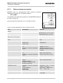
connected to one of the three audio interfaces.
Physical characteristics
Size:
35+0.15 x 32.5+0.15 x 3.1+0.3 mm (including application
connector)
35+0.15 x 32.5+0.15 x
application connector)
Weight:
2.95+0.2 mm
(excluding
5.5g
RoHS
All hardware components are fully compliant with the EU RoHS Directive
Firmware upgrade
Firmware upgradable over serial interface and SIM interface
Evaluation kit
The DSB45 Support Box is an evaluation kit designed to test and type
approve Siemens cellular engines and provide a sample configuration for
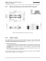
application engineering. See Chapter 9 for ordering information.
MC55/56_hd_v04.00a
Page 21 of 108
24.08.2006
s
MC55/56 Hardware Interface Description
Confidential / Released
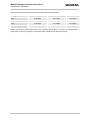
Table 2: Coding schemes and maximum net data rates over air interface
Coding scheme
1 Timeslot
2 Timeslots
4 Timeslots
CS-1:
9.05 kbps
18.1 kbps
36.2 kbps
CS-2:
13.4 kbps
26.8 kbps
53.6 kbps
CS-3:
15.6 kbps
31.2 kbps
62.4 kbps
CS-4:
21.4 kbps
42.8 kbps
85.6 kbps
Please note that the values stated above are maximum ratings which, in practice, are influenced by a
great variety of factors, primarily, for example, traffic variations and network coverage.
MC55/56_hd_v04.00a
Page 22 of 108
24.08.2006
s
MC55/56 Hardware Interface Description
Confidential / Released
2.2
Circuit concept
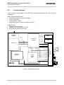
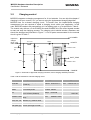
Figure 1 shows a block diagram of the MC55/56 module and illustrates the major functional
components:
GSM / GPRS baseband block:
• Baseband controller operating at 26MHz
• Power supply ASIC
• Stacked Flash / SRAM
• Application interface (board-to-board connector)
GSM RF block:
• Skyworks RF transceiver
• Skyworks RF power amplifier / FEM
• RF front end (antenna connector)
RF Power
Amplifier
Data
SRAM
Adr
Control
Interface
RF - Baseband
Baseband
Controller
Send
Data
Flash
Adr
Control
Receive
Control
CCRST
CCCLK
CCIO
4
CCIN
CCVCC
(GND)
5
DAI
9
2x Audio
8
ASC0
4
ASC1
SYNC
6
SIM Interface
2
VDD
Measuring
Network
VDDLP
/EMERGOFF
Power
Supply
ASIC
/IGT
POWER
CHARGE
MC5x
5
BATT+
5
GND
CCIN
Application Interface
(50 pins)
RF Section
CCVCC
4
SIM
Charger
input
Ext.
Charging
Circuit
NTC
+
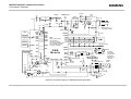
BATT_TEMP
Figure 1: MC55/56 block diagram
MC55/56_hd_v04.00a
Page 23 of 108
24.08.2006
MC55/56 Hardware Interface Description
Confidential / Released
3
s
Application Interface
MC55/56 is equipped with a 50-pin 0.5mm pitch board-to-board connector that connects to
the cellular application platform. The host interface incorporates several sub-interfaces
described in the following chapters:
• Power supply and charging control (see Chapters 3.2 and 3.3)
• Dual serial interface (see Chapter 3.9)
• Two analog audio interfaces and a digital audio interface (see Chapter 3.10)
• SIM interface (see Chapter 3.11)
Electrical and mechanical characteristics of the board-to-board connector are specified in
Chapter 6.3. Ordering information for mating connectors and cables are included.
MC55/56_hd_v04.00a
Page 24 of 108
24.08.2006
s
MC55/56 Hardware Interface Description
Confidential / Released
3.1
Operating modes
The table below briefly summarizes the various operating modes referred to in the following
chapters.
Table 3: Overview of operating modes
Mode
Function
Normal operation
GSM / GPRS SLEEP
Various powersave
command.
modes
set
with
AT+CFUN
Software is active to minimum extent. If the module was
registered to the GSM network in IDLE mode, it is
registered and paging with the BTS in SLEEP mode,
too. Power saving can be chosen at different levels: The
NON-CYCLIC SLEEP mode (AT+CFUN=0) disables the
AT interface. The CYCLIC SLEEP modes AT+CFUN=5,
6, 7, 8 and 9 alternatingly activate and deactivate the AT
interfaces to allow permanent access to all AT
commands.
POWER DOWN
GSM IDLE
Software is active. Once registered to the GSM network,
paging with BTS is carried out. The module is ready to
send and receive.
GSM TALK
Connection between two subscribers is in progress.
Power consumption depends on network coverage
individual settings, such as DTX off/on, FR/EFR/HR,
hopping sequences, antenna.
GPRS IDLE
Module is ready for GPRS data transfer, but no data is
currently sent or received. Power consumption depends
on network settings and GPRS configuration (e.g.
multislot settings).
GPRS DATA
GPRS data transfer in progress. Power consumption
depends on network settings (e.g. power control level),
uplink / downlink data rates and GPRS configuration
(e.g. used multislot settings).
Normal shutdown after sending the AT^SMSO command.
The Power Supply ASIC (PSU-ASIC) disconnects the supply voltage from the
baseband part of the circuit. Only a voltage regulator in the PSU-ASIC is active
for powering the RTC. Software is not active. The serial interfaces are not
accessible.
Operating voltage (connected to BATT+) remains applied.
Alarm mode
Restricted operation launched by RTC alert function while the module is in
POWER DOWN mode. Module will not be registered to GSM network. Limited
number of AT commands is accessible.
MC55/56_hd_v04.00a
Page 25 of 108
24.08.2006
MC55/56 Hardware Interface Description
Confidential / Released
s
Mode
Function
Charge-only mode
Limited operation for battery powered applications. Enables charging while
module is detached from GSM network. Limited number of AT commands is
accessible. There are several ways to launch Charge-only mode:
• From POWER DOWN mode: Connect charger to the charger input pin of the
external charging circuit and the module’s POWER pin when MC55/56 was
powered down by AT^SMSO.
• From Normal mode: Connect charger to the charger input pin of the external
charging circuit and the module’s POWER pin, then enter AT^SMSO.
Charge mode
during normal
operation
Normal operation (SLEEP, IDLE, TALK, GPRS IDLE, GPRS DATA) and
charging running in parallel. Charge mode changes to Charge-only mode when
the module is powered down before charging has been completed.
See Table 11 and Table 12 for the various options of waking up MC55/56 and proceeding from one
mode to another.
MC55/56_hd_v04.00a
Page 26 of 108
24.08.2006
s
MC55/56 Hardware Interface Description
Confidential / Released
3.2
Power supply
The power supply of MC55/56 has to be a single voltage source of VBATT+= 3.3V...4.8V. It
must be able to provide sufficient current in a transmit burst which typically rises to 2A.
Beyond that, the power supply must be able to account for increased current consumption if
the module is exposed to inappropriate conditions, for example antenna mismatch. For
further details see Chapters 3.2.2 and 5.6.1.
All the key functions for supplying power to the device are handled by an ASIC power
supply. The ASIC provides the following features:
• Stabilizes the supply voltages for the GSM baseband using low drop linear voltage
regulators.
• Controls the module's power up and power down procedures.
A watchdog logic implemented in the baseband processor periodically sends signals to
the ASIC, allowing it to maintain the supply voltage for all digital MC55/56 components.
Whenever the watchdog pulses fail to arrive constantly, the module is turned off.
• Delivers, across the VDD pin, a regulated voltage of 2.9V. The output voltage VDD may
be used to supply, for example, an external LED or a level shifter. However, the external
circuitry must not cause any spikes or glitches on voltage VDD. This voltage is not
available in POWER DOWN mode. Therefore, the VDD pin can be used to indicate
whether or not MC55/56 is in POWER DOWN mode.
• Provides power to the SIM interface.
The RF power amplifier is driven directly from BATT+.
3.2.1
Power supply pins on the board-to-board connector
Five BATT+ pins of the board-to-board connector are dedicated to connect the supply
voltage, five GND pins are recommended for grounding. The values stated below must be
measured directly at the reference points on the MC55/56 board (TP BATT+ and TP GND
illustrated in Figure 44).
The POWER and CHARGE pins serve as control signals for charging a Li-Ion battery.
VDDLP can be used to back up the RTC.
Table 4: Power supply pins of board-to-board connector
Signal name
I/O
Description
Parameter
BATT+
I/O
Positive operating voltage
3.3 V...4.8 V, Ityp ≤ 2 A during transmit burst
Reference points are the
test points
The minimum operating voltage must not fall
below 3.3 V, not even in case of voltage drop.
0V
GND
-
Ground
POWER
I
This line signals to the
processor that the charger
is connected.
CHARGE
O
Control signal for external
charging transistor
VDDLP
I/O
Can be used to back up the
RTC when VBATT+ is not
applied.
See Chapter 3.8
MC55/56_hd_v04.00a
UOUT,max < VBATT+
UIN = 2.0 V...5.5 V
Ri = 1kΩ
Iin,max = 30µA
Page 27 of 108
24.08.2006
s
MC55/56 Hardware Interface Description
Confidential / Released
3.2.2
Minimizing power losses
When designing the power supply for your application please pay specific attention to power
losses. Ensure that the input voltage VBATT+ never drops below 3.3V on the MC55/56 board,
not even in a transmit burst where current consumption can rise to typical peaks of 1.6A. It
should be noted that MC55/56 switches off when exceeding these limits. Any voltage drops
that may occur in a transmit burst should not exceed 400mV. For further details see Chapter
5.6.
The best approach to reducing voltage drops is to use a board-to-board connection as
recommended, and a low impedance power source. The resistance of the power supply lines
on the host board and of a battery pack should also be considered.
Note:
If the application design requires an adapter cable between both board-to-board
connectors, use a cable as short as possible in order to minimize power losses.
Example: If the length of the cable reaches the maximum length of 200mm, this connection
may cause, for example, a resistance of 50mΩ in the BATT+ line and 50mΩ in
the GND line. As a result, a 1.6A transmit burst would add up to a total voltage
drop of 160mV. Plus, if a battery pack is involved, further losses may occur due
to the resistance across the battery lines and the internal resistance of the
battery including its protective circuit.
Transmit
burst 1.6A
Transmit
burst 1.6A
BATT+
Drop
min. 3.3V
Ripple
Figure 2: Power supply limits during transmit burst
The input voltage VBATT+ must be measured directly at the test points on the MC55/56 board
(TP BATT+ and TP GND illustrated in Figure 44).
3.2.3
Monitoring power supply
To help you monitor the supply voltage you can use the AT^SBV command which returns the
voltage measured at TP BATT+ and GND.
The voltage is continuously measured at intervals depending on the operating mode on the
RF interface. The duration of measuring ranges from 0.5s in TALK/DATA mode up to 50s
when MC55/56 is in IDLE mode or Limited Service (deregistered). The displayed voltage (in
mV) is averaged over the last measuring period before the AT^SBV command was
executed.
For details please refer to [1].
MC55/56_hd_v04.00a
Page 28 of 108
24.08.2006
MC55/56 Hardware Interface Description
Confidential / Released
3.3
s
Power up / down scenarios
In general, be sure not to turn on MC55/56 while it is out of the operating range of voltage
and temperature stated in Chapters 5.2 and 5.5. MC55/56 would immediately switch off after
having started and detected these inappropriate conditions.
3.3.1
Turn on MC55/56
MC55/56 can be activated in a variety of ways, which are described in the following chapters:
• via ignition line /IGT: starts normal operating state (see Chapters 3.3.1.1 and 3.3.1.2)
• via POWER line: starts charging algorithm (see Chapters 3.3.1.3 and 3.5.3)
• via RTC interrupt: starts Alarm mode (see Chapter 3.3.1.4)
MC55/56_hd_v04.00a
Page 29 of 108
24.08.2006
s
MC55/56 Hardware Interface Description
Confidential / Released
3.3.1.1
Turn on MC55/56 using the ignition line /IGT (Power on)
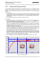
To switch on MC55/56 the /IGT (Ignition) signal needs to be driven to ground level for at
least 100ms and not earlier than 10ms after the last falling edge of VDD. This can be
accomplished using an open drain/collector driver in order to avoid current flowing into this
pin.
BATT+
min. 10ms
HiZ
min.
100ms
HiZ
/IGT
ca. 60ms
VDD
/TXD0
/TXD1
/DSR0
/EMERGOFF
Serial interfaces
ASC0 and ASC1
Software
controlled
Undefined
ca. 300ms
Inactive
Active
ca. 900ms
For details please see Chapter 3.3.1.2
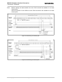
Figure 3: Power-on by ignition signal
In a battery operated MC55/56 application, the duration of the /IGT signal must be 1s
minimum when the charger is connected and you may want to go from Charge only mode to
Normal mode.
MC55/56_hd_v04.00a
Page 30 of 108
24.08.2006
s
MC55/56 Hardware Interface Description
Confidential / Released
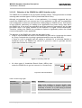
Assertion of CTS indicates that the module is ready to receive data from the host application.
In addition, if configured to a fixed bit rate (AT+IPR≠0), the module will send the URC
“^SYSSTART” which notifies the host application that the first AT command can be sent to
the module. The duration until this URC is output varies with the SIM card and may take a
couple of seconds, particularly if the request for the SIM PIN is deactivated on the SIM card.
Please note that no “^SYSSTART” URC will be generated if autobauding (AT+IPR=0) is
enabled.
To allow the application to detect the ready state of the module we recommend using
hardware flow control which can be set with AT\Q or AT+ICF (see [1] for details). The default
setting of MC55/56 is AT\Q0 (no flow control) which shall be altered to AT\Q3 (RTS/CTS
handshake). If the application design does not integrate RTS/CTS lines the host application
shall wait at least for the “^SYSSTART” URC. However, if the URCs are neither used (due to
autobauding) then the only way of checking the module’s ready state is polling. To do so, try
to send characters (e.g. “at”) until the module is responding. However, as shown in Figure 3
there should be an ample time period between ignition and before polling and sending any
AT commands. AT commands received while the interface's state is undefined may retrigger
the boot loader and the module’s startup sequence.
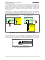
3.3.1.2
Timing of the ignition process
When designing your application platform take into account that powering up MC55/56
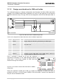
requires the following steps.
• The ignition line cannot be operated until VBATT+ passes the level of 3.0V.
• The ignition line shall not be operated earlier than 10ms after the last falling edge of VDD.
• 10ms after VBATT+ has reached 3.0V the ignition line can be switched low. The duration of
the falling edge must not exceed 1ms.
• Another 100ms are required to power up the module.
• Ensure that VBATT+ does not fall below 3.0V while the ignition line is driven. Otherwise the
module cannot be activated.
• If the VDDLP line is fed from an external power supply as explained in Chapter 3.8, the
/IGT line is HiZ before the rising edge of BATT+.
3.0V
BATT+
0V
HiZ
HiZ
/IGT
10ms
min. 100ms
max. 1ms
Figure 4: Timing of power-on process if VDDLP is not used
MC55/56_hd_v04.00a
Page 31 of 108
24.08.2006
s
MC55/56 Hardware Interface Description
Confidential / Released
3.0V
BATT+
0V
HiZ
HiZ
/IGT
10ms
min. 100ms
max. 1ms
Figure 5: Timing of power-on process if VDDLP is fed from external source
3.3.1.3
Turn on MC55/56 using the POWER signal
As detailed in Chapter 3.5.3, the charging adapter can be connected regardless of the
module’s operating mode.
If the charger is connected to the charger input of the external charging circuit and the
module’s POWER pin while MC55/56 is off, processor controlled fast charging starts (see
Chapter 3.5.2). MC55/56 enters a restricted mode, referred to as Charge-only mode where
only the charging algorithm will be launched.
During the Charge-only mode MC55/56 is neither logged on to the GSM network nor are the
serial interfaces fully accessible. To switch to normal operation and log on to the GSM
network, the /IGT line needs to be activated.
3.3.1.4
Turn on MC55/56 using the RTC (Alarm mode)
Another power-on approach is to use the RTC, which is constantly supplied with power from
a separate voltage regulator in the power supply ASIC. The RTC provides an alert function,
which allows the MC55/56 to wake up whilst the internal voltage regulators are off. To
prevent the engine from unintentionally logging into the GSM network, this procedure only
enables restricted operation, referred to as Alarm mode. It must not be confused with a
wake-up or alarm call that can be activated by using the same AT command, but without
switching off power.
Use the AT+CALA command to set the alarm time. The RTC retains the alarm time if
MC55/56 was powered down by AT^SMSO. Once the alarm is timed out and executed,
MC55/56 enters the Alarm mode. This is indicated by an Unsolicited Result Code (URC)
which reads:
^SYSSTART ALARM MODE
Note that this URC is the only indication of the Alarm mode and will not appear when
autobauding was activated (due to the missing synchronization between DTE and DCE upon
start-up). Therefore, it is recommended to select a fixed baudrate before using the Alarm
mode.
MC55/56_hd_v04.00a
Page 32 of 108
24.08.2006
MC55/56 Hardware Interface Description
Confidential / Released
s
In Alarm mode only a limited number of AT commands is available. For further instructions
refer to the AT Command Set.
Table 5: AT commands available in Alarm mode
AT command
Use
AT+CALA
Set alarm time
AT+CCLK
Set date and time of RTC
AT^SBC
In Alarm mode, you can only query the present current consumption and check
whether or not a charger is connected. The battery capacity is returned as 0,
regardless of the actual voltage (since the values measured directly on the cell are
not delivered to the module).
AT^SCTM
Query temperature range, enable/disable URCs to report critical temperature ranges
AT^SMSO
Power down GSM engine
For the GSM engine to change from the Alarm mode to full operation (normal operating
mode) it is necessary to drive the ignition line to ground. This must be implemented in your
host application as described in Chapter 3.3.1.1.
If the charger is connected to the POWER line when MC55/56 is in ALARM mode charging
will start, while MC55/56 stays in ALARM mode. See also Chapter 3.7 which summarizes the
various options of changing the mode of operation.
If your host application uses the SYNC pin to control a status LED as described in Chapter
3.12.2.2, please note that the LED is off while the GSM engine is in Alarm mode.
MC55/56_hd_v04.00a
Page 33 of 108
24.08.2006
MC55/56 Hardware Interface Description
Confidential / Released
3.3.2
s
Turn off MC55/56
To switch the module off the following procedures may be used:
•
•
•
Normal shutdown procedure: Software controlled by sending the AT^SMSO command
over the serial application interface. See Chapter 3.3.2.1.
Emergency shutdown: Hardware driven by switching the /EMERGOFF line of the boardto-board-connector to ground = immediate shutdown of supply voltages, only applicable
if the software controlled procedure fails! See Chapter 3.3.2.2.
Automatic shutdown: See Chapter 3.3.3
a) Takes effect if undervoltage is detected.
b) Takes effect if MC55/56 board temperature exceeds critical limit.
3.3.2.1
Turn off MC55/56 using AT command
The best and safest approach to powering down MC55/56 is to issue the AT^SMSO
command. This procedure lets MC55/56 log off from the network and allows the software to
enter into a secure state and safe data before disconnecting the power supply. The mode is
referred to as POWER DOWN mode. In this mode, only the RTC stays active.
Before switching off the device sends the following response:
^SMSO: MS OFF
OK
^SHUTDOWN
After sending AT^SMSO do not enter any other AT commands. There are two ways to verify
when the module turns off:
• Wait for the URC “^SHUTDOWN”. It indicates that data have been stored non-volatile
and the module turns off in less than 1 second.
• Also, you can monitor the VDD pin. The low state of VDD definitely indicates that the
module is switched off.
Be sure not to disconnect the operating voltage VBATT+ before the URC “^SHUTDOWN” has
been issued and the VDD signal has gone low. Otherwise you run the risk of losing data.
While MC55/56 is in POWER DOWN mode the application interface is switched off and
must not be fed from any other source. Therefore, your application must be designed to
avoid any current flow into any digital pins of the application interface.
Note: In POWER DOWN mode, the /EMERGOFF pin, the output pins of the ASC0 interface
/RXD0, /CTS0, /DCD0, /DSR0, /RING0 and the output pins of the ASC1 interface
/RXD1 and /CTS1 are switched to high impedance state.
If this causes the associated input pins of your application to float, you are advised to
integrate an additional resistor (100 kΩ – 1 MΩ) at each line. In the case of the
/EMERGOFF pin use a pull-down resistor tied to GND. In the case of the serial
interface pins you can either connect pull-up resistors to the VDD line, or pull-down
resistors to GND.
MC55/56_hd_v04.00a
Page 34 of 108
24.08.2006
s
MC55/56 Hardware Interface Description
Confidential / Released
3.3.2.2
Emergency shutdown using /EMERGOFF pin
Caution:
Use the /EMERGOFF pin only when, due to serious problems, the software is
not responding for more than 5 seconds. Pulling the /EMERGOFF pin causes
the loss of all information stored in the volatile memory since power is cut off
immediately. Therefore, this procedure is intended only for use in case of
emergency, e.g. if MC55/56 fails to shut down properly.
The /EMERGOFF signal is available on the board-to-board connector. To control the
/EMERGOFF line it is recommended to use an open drain / collector driver. To turn the GSM
engine off, the /EMERGOFF line has to be driven to ground for ≥ 3.2s.
BATT+
/IGT
VDD
Internal reset
max. 3.2s
/EMERGOFF
Controlled by MC55/56
software
Controlled by external application
Figure 6: Deactivating GSM engine by /EMERGOFF signal
MC55/56_hd_v04.00a
Page 35 of 108
How does it work:
• Voltage VBATT+ is permanently
applied to the module.
• The module is active while the
internal reset signal is kept at
high level.
During operation of MC55/56
the
baseband
controller
generates watchdog pulses at
regular intervals.
Once the EMERGOFF pin is
grounded
these
watchdog
pulses are cut off from the
power supply ASIC. The power
supply ASIC shuts down the
internal supply voltages of
MC55/56 after max. 3.2s and
the
module
turns
off.
Consequently,
the
output
voltage at VDD is switched off.
24.08.2006
MC55/56 Hardware Interface Description
Confidential / Released
3.3.3
s
Automatic shutdown
Automatic shutdown takes effect if
• the MC55/56 board is exceeding the critical limits of overtemperature
undertemperature
• the battery is exceeding the critical limits of overtemperature or undertemperature
• undervoltage is detected
or
The automatic shutdown procedure is equivalent to the power-down initiated with the
AT^SMSO command, i.e. MC55/56 logs off from the network and the software enters a
secure state avoiding loss of data. NOTE: This does not apply if overvoltage conditions or
unrecoverable hardware or software errors occur (see below for details).
Alert messages transmitted before the device switches off are implemented as Unsolicited
Result Codes (URCs). The presentation of these URCs can be enabled or disabled with the
two AT commands AT^SBC and AT^SCTM. The URC presentation mode varies with the
condition, please see Chapters 3.3.3.1 to 3.3.3.4 for details. For further instructions on AT
commands refer to [1].
3.3.3.1
Thermal shutdown
The board temperature is constantly monitored by an internal NTC resistor located on the
PCB. The NTC that detects the battery temperature must be part of the battery pack circuit
as described in Chapter 3.5. The values detected by either NTC resistor are measured
directly on the board or the battery and therefore, are not fully identical with the ambient
temperature.
Each time the board or battery temperature goes out of range or back to normal, MC55/56
instantly displays an alert (if enabled).
• URCs indicating the level "1" or "-1" allow the user to take appropriate precautions, such
as protecting the module from exposure to extreme conditions. The presentation of the
URCs depends on the settings selected with the AT^SCTM write command:
AT^SCTM=1: Presentation of URCs is always enabled.
AT^SCTM=0 (default): Presentation of URCs is enabled for 15 seconds time after
start-up of MC55/56. After 15 seconds operation, the presentation will be disabled,
i.e. no alert messages can be generated.
• URCs indicating the level "2" or "-2" are instantly followed by an orderly shutdown. The
presentation of these URCs is always enabled, i.e. they will be output even though the
factory setting AT^SCTM=0 was never changed.
The maximum temperature ratings are stated in Chapter 5.2. Refer to Table 6 for the
associated URCs.
MC55/56_hd_v04.00a
Page 36 of 108
24.08.2006
MC55/56 Hardware Interface Description
Confidential / Released
s
Table 6: Temperature dependent behavior
Sending temperature alert (15 s after start-up, otherwise only if URC presentation enabled)
^SCTM_A: 1
Caution: Battery close to over temperature limit.
^SCTM_B: 1
Caution: Board close to over temperature limit.
^SCTM_A: -1
Caution: Battery close to under temperature limit.
^SCTM_B: -1
Caution: Board close to under temperature limit.
^SCTM_A: 0
Battery back to uncritical temperature range.
^SCTM_B: 0
Board back to uncritical temperature range.
Automatic shutdown (URC appears no matter whether or not presentation was enabled)
^SCTM_A: 2
Alert: Battery equal or beyond over temperature limit. MC55/56 switches off.
^SCTM_B: 2
Alert: Board equal or beyond over temperature limit. MC55/56 switches off.
^SCTM_A: -2
Alert: Battery equal or below under temperature limit. MC55/56 switches off.
^SCTM_B: -2
Alert: Board equal or below under temperature limit. MC55/56 switches off.
3.3.3.2
Temperature control during emergency call
If the temperature limit is exceeded while an emergency call is in progress the engine
continues to measure the temperature, but deactivates the shutdown functionality. If the
temperature is still out of range when the call ends, the module switches off immediately
(without another alert message).
3.3.3.3
Undervoltage shutdown if battery NTC is present
In applications where the module’s charging technique is used and an NTC is connected to
the BATT_TEMP terminal, the software constantly monitors the applied voltage. If the
measured battery voltage is no more sufficient to set up a call the following URC will be
presented:
^SBC: Undervoltage.
The message will be reported, for example, when you attempt to make a call while the
voltage is close to the critical limit and further power loss is caused during the transmit burst.
To remind you that the battery needs to be charged soon, the URC appears several times
before the module switches off.
To enable or disable the URC use the AT^SBC command. The URC will be enabled when
you enter the write command and specify the power consumption of your GSM application.
Step by step instructions are provided in [1].
MC55/56_hd_v04.00a
Page 37 of 108
24.08.2006
MC55/56 Hardware Interface Description
Confidential / Released
3.3.3.4
s
Undervoltage shutdown if no battery NTC is present
The undervoltage protection is also effective in applications, where no NTC connects to the
BATT_TEMP terminal. Thus, you can take advantage of this feature even though the
application handles the charging process or MC55/56 is fed by a fixed supply voltage. All you
need to do is executing the write command AT^SBC=<current> which automatically enables
the presentation of URCs. You do not need to specify <current>.
Whenever the supply voltage falls below the specified value (see Table 31) the URC
^SBC: Undervoltage
appears several times before the module switches off.
3.3.3.5
Overvoltage shutdown
For overvoltage conditions, no software controlled shutdown is implemented. If the supply
voltage exceeds the maximum value specified in Table 31, loss of data and even
unrecoverable hardware damage can occur.
Keep in mind that several MC55/56 components are directly linked to BATT+ and, therefore,
the supply voltage remains applied at major parts of MC55/56. Especially the power amplifier
is very sensitive to high voltage and might even be destroyed.
MC55/56_hd_v04.00a
Page 38 of 108
24.08.2006
MC55/56 Hardware Interface Description
Confidential / Released
3.4
s
Automatic GPRS Multislot Class change
Temperature control is also effective for operation in GPRS Multislot Class 10. If the board
temperature increases to the limit specified for restricted operation1) while data are
transmitted over GPRS, the module automatically reverts from GPRS Multislot Class 10 (2
Tx) to Class 8 (1Tx). This reduces the power consumption and, consequently, causes the
board’s temperature to decrease. Once the temperature drops to a value of 5 degrees below
the limit of restricted operation, MC55/56 returns to the higher Multislot Class. If the
temperature stays at the critical level or even continues to rise, MC55/56 will not switch back
to the higher class.
After a transition from Multislot Class 10 to Multislot 8 a possible switchback to Multislot
Class 10 is blocked for one minute.
Please note that there is not one single cause of switching over to a lower GPRS Multislot
Class. Rather it is the result of an interaction of several factors, such as the board
temperature that depends largely on the ambient temperature, the operating mode and the
transmit power. Furthermore, take into account that there is a delay until the network
proceeds to a lower or, accordingly, higher Multislot Class. The delay time is network
dependent. In extreme cases, if it takes too much time for the network and the temperature
cannot drop due to this delay, the module may even switch off as described in chapter
3.3.3.1.
1)
See Chapter 5.2 for temperature limits known as restricted operation.
MC55/56_hd_v04.00a
Page 39 of 108
24.08.2006
s
MC55/56 Hardware Interface Description
Confidential / Released
3.5
Charging control
MC55/56 integrates a charging management for Li-Ion batteries. You can skip this chapter if
charging is not your concern, or if you are not using the implemented charging algorithm.
MC55/56 has no on-board charging circuit. To benefit from the implemented charging
management you are required to install a charging circuit within your application. In this
case, MC55/56 needs to be powered from a Li-Ion battery pack, e.g. as specified in Table 8.
The module only delivers, via its POWER line and CHARGE line, the control signals needed
to start and stop the charging process. The charging circuit should include a transistor and
should be designed as illustrated in Figure 7. A list of parts recommended for the external
circuit is given in Table 7.
to POWER
Input from
charger
(5.5V - 8V)
under load
1SS355
100 - 470R
to BATT+
4V3
1/
5
Battery
pack
PCB spark
gap
ESDA6V1-5W6
CRS04
SI3441DV
NTC
100nF
10k
+
-
3k3
BATT_TEMP
1/
5
ESDA6V1-5W6
CHARGE
Figure 7: Schematic of approved charging transistor, trickle charging and ESD protection
Table 7: Bill of material for external charging circuit
Part
Description
SI3441DV
p-chan 2.5V (G-S) MOSFET
VISHAY: SI3441DV-T1
(TSOP-6)
NEC:
1SS355
100mA Si-diode (UMD2)
ROHM:
Toshiba: 1SS352TPH3
CRS04
1A Schottky diode
Toshiba: CRS04
4V3
250mW; 200mA;
4.3V Z-Diode (SOD323)
Philips:
ESDA6V1-5W6
ESD protection TRANSIL™
STM:
array
470R, 3k3, 10k
Resistor, e.g. 0805 or 0603
-
-
100nF
Ceramic capacitor 50V
-
-
PCB spark gap
0.2mm spark gap on PCB
-
-
MC55/56_hd_v04.00a
First supplier
Page 40 of 108
1SS355TE-18
PDZ4.3B
ESDA6V1-5W6
Second supplier
UPA1911TE-T1
ROHM:
UDZS4.3B
UDZ4.3B
-
24.08.2006
s
MC55/56 Hardware Interface Description
Confidential / Released
3.5.1
Battery pack characteristics
The charging algorithm has been optimised for a Li-Ion battery pack that meets the
characteristics listed below and in Table 8. It is recommended that the battery pack you want
to integrate into your MC55/56 application is compliant with these specifications. This
ensures reliable operation, proper charging and, particularly, allows you to monitor the
battery capacity using the AT^SBC command (see [1] for details). Failure to comply with
these specifications might cause AT^SBC to deliver incorrect battery capacity values.
•
•
•
•
•
•
•
Li-Ion battery pack specified for a maximum charging voltage of 4.2V and a capacity of
800mAh. Battery packs with a capacity down to 600mAh or more than 800mAh are
allowed, too.
Since charging and discharging largely depend on the battery temperature, the battery
pack should include an NTC resistor. If the NTC is not inside the battery it must be in
thermal contact with the battery. The NTC resistor must be connected between
BATT_TEMP and GND. Required NTC characteristics are: 10kΩ +5% @ 25°C, B25/85 =
3435K +3% (alternatively acceptable: 10kΩ +2% @ 25°C, B25/50 = 3370K +3%). Please
note that the NTC is indispensable for proper charging, i.e. the charging process will not
start if no NTC is present.
Ensure that the pack incorporates a protection circuit capable of detecting overvoltage
(protection against overcharging), undervoltage (protection against deep discharging)
and overcurrent. The circuit must be insensitive to pulsed current.
On the MC55/56 module, a built-in measuring circuit constantly monitors the supply
voltage. In the event of undervoltage, it causes MC55/56 to power down. Undervoltage
thresholds are specific to the battery pack and must be evaluated for the intended model.
When you evaluate undervoltage thresholds, consider both the current consumption of
MC55/56 and of the application circuit.
The internal resistance of the battery and the protection should be as low as possible. It
is recommended not to exceed 150mΩ, even in extreme conditions at low temperature.
The battery cell must be insensitive to rupture, fire and gassing under extreme conditions
of temperature and charging (voltage, current).
The battery pack must be protected from reverse pole connection. For example, the
casing should be designed to prevent the user from mounting the battery in reverse
orientation.
The battery pack must be approved to satisfy the requirements of CE conformity.
Figure 8 shows the circuit diagram of a typical to BATT+
battery pack design that includes the
protection elements described above.
to BATT_TEMP
to GND
ϑ
NTC
Protection Circuit
+ Battery cell
Figure 8: Battery pack circuit diagram
MC55/56_hd_v04.00a
Page 41 of 108
Polyfuse
24.08.2006
MC55/56 Hardware Interface Description
Confidential / Released
s
Table 8: Specifications of recommended battery pack
Battery type
Li-Ion, 3.6V
Nominal voltage
3.6V
Capacity
800mAh
NTC
10kΩ ± 5% @ 25°C, B (25/85)=3435K ± 3%
Overcharge detection voltage
4.325 ± 0.025V
Overcharge release voltage
4.075 ± 0.025V
Overdischarge detection voltage
2.5 ± 0.05V
Overdischarge release voltage
2.9 ± 0.5V
Overcurrent detection
3 ± 0.5A
Nominal working current
<5µA
Current of low voltage detection
0.5µA
Overcurrent detection delay time
8~16ms
Short detection delay time
50µs
Overdischarge detection delay time
31~125ms
Overcharge detection delay time
1s
Internal resistance
<130mΩ
MC55/56_hd_v04.00a
Page 42 of 108
24.08.2006
MC55/56 Hardware Interface Description
Confidential / Released
3.5.2
s
Implemented charging technique
If the external charging circuit follows the recommendation of Figure 7, the charging process
consists of trickle charging and processor controlled fast charging. For this solution, the fast
charging current provided by the charger or any other external source must be limited to
500mA.
Trickle charging
• Trickle charging starts when the charger is connected to the charger input of the external
charging circuit and the module’s POWER pin. The charging current depends on the
voltage difference between the charger input of the external charging circuit and BATT+
of the module.
• Trickle charging stops when the battery voltage reaches 3.6V.
Fast charging
• After trickle charging has raised the battery voltage to 3.2V within 60 minutes +10% from
connecting the charger, the power ASIC turns on and wakes up the baseband processor.
Now, processor controlled fast charging begins.
However, if the battery was deeply discharged (below 2.2V) the power ASIC does not
wake up the baseband processor and fast charging does not begin after the battery
voltage has reached 3.2V. In this case, disconnect and reconnect the charger once after
the battery voltage has risen above 2.2V.
If the battery voltage was already above 3.2V, processor controlled fast charging starts
just after the charger was connected to the charger input of the external charging circuit
and the module’s POWER pin. If MC55/56 was in POWER DOWN mode, it turns on and
enters the Charge-only mode along with fast charging (see also Chapter 3.3.1.3).
• Fast charging delivers a constant current until the battery voltage reaches 4.2V and then
proceeds with varying charge pulses. As shown in Figure 5, the pulse duty cycle is
reduced to adjust the charging procedure and prevent the voltage from overshooting
beyond 4.2V. Once the pulse width reaches the minimum of 100ms and the duty cycle
does not change for 2 minutes, fast charging is completed.
• Fast charging can only be accomplished in a temperature range from 0°C to +45°C.
Voltage
4.3
4.2
3.8
3.4
100ms 2 ... 0.1s
100ms 0.1 ... 2s
3.0
Constant current
tOFF = 100 ms
tON = 100 ms
Time
Figure 9: Charging process
MC55/56_hd_v04.00a
Page 43 of 108
24.08.2006
s
MC55/56 Hardware Interface Description
Confidential / Released
Note:
Do not connect the charger to the BATT+ lines. Only the charger input of the
external charging circuit is intended as input for charging current! The POWER pin
of MC55/56 is the input only for indicating a connected charger!
The battery manufacturer must guarantee that the battery complies with the
described charging technique.
What to do if software controlled charging does not start up?
If trickle charging fails to raise the battery voltage to 3.2V within 60 minutes +10%, processor
controlled charging does not begin. To start fast charging you can do one of the following:
• Once the voltage has risen above its minimum of 3V, you can try to start software
controlled charging by pulling the /IGT line to ground.
• If the voltage is still below 3V, driving the /IGT line to ground switches the timer off.
Without the timer running, MC55/56 will not proceed to software controlled charging. To
restart the timer you are required to shortly disconnect and reconnect the charger.
3.5.3
Operating modes during charging
Of course, the battery can be charged regardless of the engine's operating mode. When the
GSM engine is in Normal mode (SLEEP, IDLE, TALK, GPRS IDLE or GPRS DATA mode), it
remains operational while charging is in progress (provided that sufficient voltage is applied).
The charging process during the Normal mode is referred to as Charge mode.
If the charger is connected to the charger input of the external charging circuit and the
module’s POWER pin while MC55/56 is in POWER DOWN mode, MC55/56 goes into
Charge-only mode.
Table 9: Comparison Charge-only and Charge mode
Charge-only mode
Charge mode
How to activate mode
Features
Connect charger to charger input of • Battery can be charged while GSM engine
external charging circuit and module’s
remains operational and registered to the
POWER pin while MC55/56 is
GSM network.
•
In IDLE and TALK mode, the serial interfaces
• operating, e.g. in IDLE or TALK mode
are
accessible. AT command set can be used
• in SLEEP mode
to full extent.
• In the NON-CYCLIC SLEEP mode, the serial
interfaces are not accessible at all. During the
CYCLIC SLEEP mode it can be used as
described in Chapter 3.6.3.
Connect charger to charger input of • Battery can be charged while GSM engine is
external charging circuit and module’s
deregistered from GSM network.
POWER pin while MC55/56 is
• Charging runs smoothly due to constant
current consumption.
• in POWER DOWN mode
•
The AT interface is accessible and allows to
• in Normal mode: Connect charger to
use
the commands listed below.
the
POWER
pin, then enter
AT^SMSO.
IMPORTANT: While trickle charging is in
progress, be sure that the application is
switched off. If the application is fed from
the trickle charge current the module
might be prevented from proceeding to
software controlled charging since the
current would not be sufficient.
MC55/56_hd_v04.00a
Page 44 of 108
24.08.2006
MC55/56 Hardware Interface Description
Confidential / Released
s
Features of Charge-only mode
Once the GSM engine enters the Charge-only mode, the AT command interface presents an
Unsolicited Result Code (URC) which reads:
^SYSSTART CHARGE-ONLY MODE
Note that this URC will not appear when autobauding was activated (due to the missing
synchronization between DTE and DCE upon start-up). Therefore, it is recommended to
select a fixed baud rate before using the Charge-only mode.
While the Charge-only mode is in progress, you can only use the AT commands listed in
Table 10. For further instructions refer to the AT Command Set supplied with your GSM
engine.
Table 10: AT commands available in Charge-only mode
AT command
Use
AT+CALA
Set alarm time
AT+CCLK
Set date and time of RTC
AT^SBC
Monitor charging process
AT^SCTM
Note: While charging is in progress, no battery capacity value is available. To query
the battery capacity disconnect the charger.
If the charger connects externally to the host device no charging parameters are
transferred to the module. In this case, the command cannot be used.
Query temperature range, enable/disable URCs to report critical temperature ranges
AT^SMSO
Power down GSM engine
To proceed from Charge-only mode to normal operation, it is necessary to drive the ignition
line to ground. This must be implemented in your host application as described in Chapter
3.3.1.1. See also Chapter 3.7 which summarizes the various options of changing the mode
of operation.
If your host application uses the SYNC pin to control a status LED as described in Chapter
3.12.2.2, please note that the LED is off while the GSM engine is in Charge-only mode.
3.5.4
Charger requirements
If you are using the implemented charging technique and the charging circuit recommended
in Figure 7, the charger must be designed to meet the following requirements:
a) Simple transformer power plug
- Output voltage: 5.5V...8V (under load)
- The charge current must be limited to 500mA
- Voltage spikes that may occur while you connect or disconnect the charger must be
limited.
- There must not be any capacitor on the secondary side of the power plug (avoidance of
current spikes at the beginning of charging)
b) Supplementary requirements for a) to ensure a regulated power supply
- When current is switched off a voltage peak of 10V is allowed for a maximum 1ms
- When current is switched on a spike of 1.6A for 1ms is allowed
MC55/56_hd_v04.00a
Page 45 of 108
24.08.2006
MC55/56 Hardware Interface Description
Confidential / Released
3.6
s
Power saving
SLEEP mode reduces the functionality of the MC55/56 module to a minimum and, thus,
minimizes the current consumption to the lowest level. Settings can be made using the
AT+CFUN command. For details see below and [1]. SLEEP mode falls into two categories:
• NON-CYCLIC SLEEP mode AT+CFUN=0
• CYCLIC SLEEP modes, selectable with AT+CFUN=5, 6, 7, 8 or 9.
IMPORTANT: Please keep in mind that power saving works properly only when PIN
authentication has been done. If you attempt to activate power saving while the SIM card is
not inserted or the PIN not correctly entered (Limited Service), the selected <fun> level will
be set, though power saving does not take effect. For the same reason, power saving
cannot be used if MC55/56 operates in Alarm mode.
To check whether power saving is on, you can query the status of AT+CFUN if you have
chosen CYCLIC SLEEP mode. If available, you can take advantage of the status LED
controlled by the SYNC pin (see Chapter 3.12.2.2). The LED is off in all SLEEP modes when
no activity occurs, but resumes flashing to indicate temporary wake-up states during
CYLCIC SLEEP modes. The LED patterns are shown in Table 18.
The wake-up procedures are quite different depending on the selected SLEEP mode. Table
11 compares the wake-up events that can occur in NON-CYCLIC and CYCLIC SLEEP
modes.
3.6.1
No power saving (AT+CFUN=1)
The functionality level <fun>=1 is where power saving is switched off. This is the default after
startup.
3.6.2
NON-CYCLIC SLEEP mode (AT+CFUN=0)
If level 0 has been selected (AT+CFUN=0), the serial interface is blocked. The module
shortly deactivates power saving to listen to a paging message sent from the base station
and then immediately resumes power saving. Level 0 is called NON-CYCLIC SLEEP mode,
since the serial interface is not alternatingly made accessible as in CYCLIC SLEEP mode.
The first wake-up event fully activates the module, enables the serial interface and
terminates the power saving mode. In short, it takes MC55/56 back to the highest level of
functionality <fun>=1.
In NON-CYCLIC mode, the falling edge of the /RTS0 or /RTS1 lines wakes up the module to
<fun>=1. To efficiently use this feature it is recommended to enable hardware flow control
(RTS/CTS handshake) as in this case the CTS line notifies the application when the module
is ready to send or receive characters. See section 3.6.6.1 for details.
MC55/56_hd_v04.00a
Page 46 of 108
24.08.2006
MC55/56 Hardware Interface Description
Confidential / Released
3.6.3
s
CYCLIC SLEEP mode (AT+CFUN=5, 6, 7, 8)
The functionality levels AT+CFUN=5, AT+CFUN=6, AT+CFUN=7 and AT+CFUN=8 are
referred to as CYCLIC SLEEP modes. The major benefit of all CYCLIC SLEEP modes is
that the serial interface remains accessible, and that, in intermittent wake-up periods,
characters can be sent or received without terminating the selected mode.
The CYCLIC SLEEP modes give you greater flexibility regarding the wake-up procedures:
For example, in all CYCLIC SLEEP modes, you can enter AT+CFUN=1 to permanently wake
up the module. In modes CFUN=7 and 8, MC55/56 automatically resumes power saving,
after you have sent or received a short message, made a call or completed a GPRS transfer.
CFUN=5 and 6 do not offer this feature, and therefore, are only supported for compatibility
with earlier releases. Please refer to Table 11 for a summary of all modes.
The CYCLIC SLEEP mode is a dynamic process which alternatingly enables and disables
the serial interface. By setting/resetting the /CTS signal, the module indicates to the
application whether or not the UART is active. The timing of /CTS is described below.
Both the application and the module must be configured to use hardware flow control
(RTS/CTS handshake). The default setting of MC55/56 is AT\Q0 (no flow control) which
must be altered to AT\Q3. See [1] for details.
Note: If both serial interfaces ASC0 and ASC1 are connected, both are synchronized. This
means that SLEEP mode takes effect on both, no matter on which interface the AT
command was issued. Although not explicitly stated, all explanations given in this
chapter refer equally to ASC0 and ASC1, and accordingly to /CTS0 and /CTS1.
3.6.4
CYCLIC SLEEP mode AT+CFUN=9
Mode AT+CFUN=9 is similar to AT+CFUN=7 or 8, but provides two additional features:
• The time the module stays active after RTS was asserted or after the last character was
sent or received, can be configured individually using the command AT^SCFG. Default
setting is 2 seconds like in AT+CFUN=7. The entire range is from 0.5 seconds to 1 hour,
selectable in tenths of seconds. For details see [1].
• /RTS0 and /RTS1 are not only used for flow control (as in modes AT+CFUN=5, 6, 7 or
8), but also cause the module to wake up temporarily. See section 3.6.6.1 for details.
3.6.5
Timing of the /CTS signal in CYCLIC SLEEP modes
The /CTS signal is enabled in synchrony with the module’s paging cycle. It goes active low
each time when the module starts listening to a paging message block from the base station.
The timing of the paging cycle varies with the base station. The duration of a paging interval
can be calculated from the following formula:
4.615 ms (TDMA frame duration) * 51 (number of frames) * DRX value.
DRX (Discontinuous Reception) is a value from 2 to 9, resulting in paging intervals from 0.47
to 2.12 seconds. The DRX value of the base station is assigned by the network operator.
Each listening period causes the /CTS signal to go active low: If DRX is 2, the /CTS signal is
activated every 0.47 seconds, if DRX is 3, the /CTS signal is activated every 0.71 seconds
and if DRX is 9, the /CTS signal is activated every 2.1 seconds.
MC55/56_hd_v04.00a
Page 47 of 108
24.08.2006
s
MC55/56 Hardware Interface Description
Confidential / Released
The /CTS signal is active low for 4.6 ms. This is followed by another 4.6 ms UART activity. If
the start bit of a received character is detected within these 9.2 ms, /CTS will be activated
and the proper reception of the character will be guaranteed.
/CTS will also be activated if any character is to be sent.
After the last character was sent or received the interface will remain active for
• another 2 seconds, if AT+CFUN=5 or 7,
• another 10 minutes, if AT+CFUN=6 or 8,
• or for an individual time defined with AT^SCFG, if AT+CFUN=9. Assertion of RTS has
the same effect.
In the pauses between listening to paging messages, while /CTS is high, the module
resumes power saving and the AT interface is not accessible. See Figure 10 and Figure 11.
Paging message
Paging message
2.12 s
/CTS
Paging message
4.6
ms
4.6
ms
4.6 ms
4.6
ms
4.6
ms
4.6 ms
AT interface disabled
Paging message
2.12 s
2.12 s
4.6 ms
4.6 ms
AT interface enabled
Figure 10: Timing of /CTS signal (example for a 2.12 s paging cycle)
Figure 11 illustrates the CFUN=5 and CFUN=7 modes, which reset the /CTS signal 2
seconds after the last character was sent or received.
Paging message
2.12 s
Paging message
2.12 s
Paging message
2.12 s
Paging message
Beginning of power saving
4.6
ms
/CTS
2s
st
1 character
4.6 ms
4.6
ms
4.6 ms
4.6 ms
Last character
AT interface disabled
AT interface enabled
Figure 11: Beginning of power saving if CFUN=5 or 7
MC55/56_hd_v04.00a
Page 48 of 108
24.08.2006
s
MC55/56 Hardware Interface Description
Confidential / Released
3.6.6
Wake up MC55/56 from SLEEP mode
A wake-up event is any event that causes the module to draw current. Depending on the
selected mode the wake-up event either switches SLEEP mode off and takes MC55/56 back
to AT+CFUN=1, or activates MC55/56 temporarily without leaving the current SLEEP mode.
Definitions of the state transitions described in Table 11:
Quit
= MC55/56 exits SLEEP mode and returns to AT+CFUN=1.
Temporary
= MC55/56 becomes active temporarily for the duration of the event and the
mode-specific follow-up time after the last character was sent or received
on the serial interface.
No effect:
= Event is not relevant in the selected SLEEP mode. MC55/56 does not
wake up.
Table 11: Wake-up events in NON-CYCLIC and CYCLIC SLEEP modes
Event
Selected mode
AT+CFUN=0
Selected mode
AT+CFUN=5 or 6
Selected mode
AT+CFUN=7, 8, 9
Ignition line
No effect
No effect
No effect
/RTS0 or /RTS1 1)
(falling edge)
Quit + flow control
No effect, RTS is only Mode 7 and 8: No
used for flow control
effect, RTS is only
used for flow control
Mode 9: Temporary +
flow control
Unsolicited Result Code
(URC)
Quit
Quit
Temporary
Incoming voice or data call
Quit
Quit
Temporary
Any AT command
(incl. outgoing voice or data
call, outgoing SMS)
Not possible
(UART disabled)
Temporary
Temporary
AT+CNMI=0,0 (= default, no
indication of received SMS)
No effect
No effect
No effect
AT+CNMI=1,1 (= displays
URC upon receipt of SMS)
Quit
Quit
Temporary
GPRS data transfer
Not possible
(UART disabled)
Temporary
Temporary
RTC alarm2)
Quit
Quit
Temporary
AT+CFUN=1
Not possible
(UART disabled)
Quit
Quit
Incoming SMS depending on
mode selected by AT+CNMI:
1)
2)
See section 3.6.6.1 on wake-up via RTS.
Recommendation: In NON-CYCLIC SLEEP mode, you can set an RTC alarm to wake
up MC55/56 and return to full functionality. This is a useful approach because, in this
mode, the AT interface is not accessible.
MC55/56_hd_v04.00a
Page 49 of 108
24.08.2006
MC55/56 Hardware Interface Description
Confidential / Released
3.6.6.1
s
Wake-up via /RTS0 and RTS1 (if AT+CFUN=0 or AT+CFUN=9)
During the CYCLIC SLEEP modes 5, 6, 7, and 8, the /RTS0 and /RTS1 lines are
conventionally used for flow control: The assertion of /RTS0 or /RTS1 indicates that the
application is ready to receive data - without waking up the module.
If the module is in CFUN=0 mode the assertion of /RTS0 and /RTS1 serves as a wake-up
event, giving the application the possibility to intentionally terminate power saving. If the
module is in CFUN=9 mode, the assertion of /RTS0 or /RTS1 can be used to temporarily
wake up MC55/56 for the time specified with the AT^SCFG command (default = 2s). In both
cases, if /RTS0 or /RTS1 is asserted while AT+CFUN=0 or AT+CFUN=9 is set, there may be
a short delay until the module is able to receive data again. This delay depends on the
current module activities (e.g. paging cycle) and may be up to 60ms. The ability to receive
data is signalized by /CTS0 and /CTS1. It is therefore recommended to enable RTS/CTS
flow control, not only in CYCLIC SLEEP mode, but also in NON-CYCLIC SLEEP mode.
MC55/56_hd_v04.00a
Page 50 of 108
24.08.2006
s
MC55/56 Hardware Interface Description
Confidential / Released
3.7
Summary of state transitions (except SLEEP mode)
Table 12: State transitions of MC55/56 (except SLEEP mode)
The table shows how to proceed from one mode to another (grey column = present mode, white columns = intended modes)
Further mode ÎÎÎ
**)
*)
Normal mode
Charge-only mode
Charging in normal
*)**)
mode
---
/IGT >100 ms at low
level
Connect charger to
input of ext. charging
circuit and POWER pin
(high level at POWER)
No direct transition, but
Wake-up from POWER
via “Charge-only mode” or DOWN mode (if
“Normal mode”
activated with AT+CALA)
/IGT >1 s at low level,
if battery is fully
charged
100ms < /IGT < 500ms
at low level
/IGT >1 s at low level
Present mode
POWER DOWN
mode without charger
--POWER DOWN
mode with charger
(high level at POWER
pins of MC55/56)
**)
Normal mode
AT^SMSO
--or
exceptionally /EMERGOFF
pin > 3.2s at low level
*)
Alarm mode
POWER DOWN
Wake-up from POWER
DOWN mode (if
activated with AT+CALA)
No automatic transition, Connect charger to
but via “POWER
POWER pin at MC55/56
DOWN”
(high level at POWER)
AT+CALA followed by
AT^SMSO. MC55/56
enters Alarm mode when
specified time is reached.
Disconnect charger
(MC55/56 POWER pin at
low level)
or AT^SMSO or
exceptionally /EMERGOFF
pin >3.2s at low level
No automatic
transition, but via
“Charge in Normal
mode”
---
/IGT >1s at low level
AT+CALA followed by
AT^SMSO. MC55/56
enters Alarm mode when
specified time is reached
and VBATT+>3.2V
Charging in normal
*) **)
mode
AT^SMSO Î “Charge-only
mode”, again AT^SMSO;
or exceptionally /EMERGOFF pin >3.2s at low level
Disconnect charger
from input of ext.
charging circuit and
module’s POWER pin
AT^SMSO
---
No direct transition
Alarm mode
AT^SMSO or
/IGT >100ms at low
exceptionally /EMERGOFF level
pin >3.2s at low level
AT^SMSO if charger is
connected
/IGT >100ms at low level
---
Charge-only mode
*)
See Chapter 3.5.3 for details on the charging mode
MC55/56_hd_v04.00a
**)
Normal mode covers TALK, DATA, GPRS, IDLE and SLEEP modes
Page 51 of 108
24.08.2006
s
MC55/56 Hardware Interface Description
Confidential / Released
3.8
RTC backup
The internal Real Time Clock of MC55/56 is supplied from a separate voltage regulator in
the power supply ASIC which is also active when MC55/56 is in POWER DOWN status. An
alarm function is provided that allows to wake up MC55/56 without logging on to the GSM
network.
In addition, you can use the VDDLP pin on the board-to-board connector to backup the RTC
from an external capacitor or a battery (rechargeable or non-chargeable). The capacitor is
charged by the BATT+ line of MC55/56. If the voltage supply at BATT+ is disconnected the
RTC can be powered by the capacitor. The size of the capacitor determines the duration of
buffering when no voltage is applied to MC55/56, i.e. the greater capacitor the longer
MC55/56 will save the date and time.
The following figures show various sample configurations. The voltage applied at VDDLP
can be in the range from 2 to 5.5V. Please refer to Table 30 for the parameters required.
BATT+
Baseband
processor
B2B
PSU
1k
RTC
VDDLP
+
Figure 12: RTC supply from capacitor
BATT+
Baseband
processor
B2B
PSU
1k
RTC
VDDLP
+
Figure 13: RTC supply from rechargeable battery
BATT+
Baseband
processor
B2B
PSU
1k
RTC
VDDLP
+
+
Figure 14: RTC supply from non-chargeable battery
MC55/56_hd_v04.00a
Page 52 of 108
24.08.2006
s
MC55/56 Hardware Interface Description
Confidential / Released
3.9
Serial interfaces
MC55/56 offers two unbalanced, asynchronous serial interfaces conforming to ITU-T V.24
protocol DCE signalling. The electrical characteristics do not comply with ITU-T V.28. The
significant levels are 0V (for low data bit or ON condition) and 2.65V (for high data bit or OFF
condition). For electrical characteristics please refer to Table 30.
The GSM engine is designed for use as a DCE. Based on the conventions for DCE-DTE
connections it communicates with the customer application (DTE) using the following
signals:
ASC0
• Port /TXD @ application sends data to the module’s /TXD0 signal line
• Port /RXD @ application receives data from the module’s /RXD0 signal line
ASC1
• Port /TXD @ application sends data to module’s /TXD1 signal line
• Port /RXD @ application receives data from the module’s /RXD1 signal line
GSM module
Application
/TXD
/RXD0
/RXD
/RTS0
/RTS
/CTS0
/CTS
/DTR0
/DTR
/DSR0
/DSR
/DCD0
/DCD
/RING0
/RING
/TXD1
/TXD
/RXD1
/RXD
/RTS1
/RTS
/CTS1
/CTS
2nd serial interface
ASC0 interface
ASC1 interface
/TXD0
1st serial interface
(DTE)
(DCE)
Figure 15: Serial interfaces
MC55/56_hd_v04.00a
Page 53 of 108
24.08.2006
s
MC55/56 Hardware Interface Description
Confidential / Released
3.9.1
Features supported on first and second serial interface
ASC0
• 8-wire serial interface
• Includes the data lines /TXD0 and /RXD0, the status lines /RTS0 and /CTS0 and, in
addition, the modem control lines /DTR0, /DSR0, /DCD0 and /RING0.
• It is primarily designed for voice calls, CSD calls, fax calls and GPRS services and for
controlling the GSM engine with AT commands. Full Multiplex capability allows the
interface to be partitioned into three virtual channels, yet with CSD and fax services only
available on the first logical channel. Please note that when the ASC0 interface runs in
Multiplex mode, ASC1 cannot be used. For more detailed characteristics see [10].
• The /DTR0 signal will only be polled once per second from the internal firmware of
MC55/56.
• The /RING0 signal serves to indicate incoming calls and other types of URCs
(Unsolicited Result Code). It can also be used to send pulses to the host application, for
example to wake up the application from power saving state. For further details see
Chapter 3.12.2.3.
• Autobauding is only selectable on ASC0 and supports the following bit rates: 1200, 2400,
4800, 9600, 19200, 38400, 57600, 115200, 230400 bps.
• Autobauding is not compatible with multiplex mode, see [10].
ASC1
• 4-wire serial interface
• Includes only the data lines /TXD1 and /RXD1 plus /RTS1 and /CTS1 for hardware
handshake. This interface is intended for voice calls, GPRS services and for controlling
the GSM engine with AT commands. It is not suited for CSD calls, fax calls and Multiplex
mode.
• On ASC1 no RING line is available. The indication of URCs on the second interface
depends on the settings made with the AT^SCFG command. For details refer to [1].
ASC0 and ASC1
• Both interfaces are configured for 8 data bits, no parity and 1 stop bit, and can be
operated at bit rates from 300bps to 230400 bps.
• XON/XOFF software flow control can be used on both interfaces (except if power saving
is active).
st
Table 13: DCE-DTE wiring of 1 serial interface
V.24
circuit
DCE
DTE
Pin function
Signal direction
Pin function
Signal direction
103
/TXD0
Input
/TXD
Output
104
/RXD0
Output
/RXD
Input
105
/RTS0
Input
/RTS
Output
106
/CTS0
Output
/CTS
Input
108/2
/DTR0
Input
/DTR
Output
107
/DSR0
Output
/DSR
Input
109
/DCD0
Output
/DCD
Input
125
/RING0
Output
/RING
Input
MC55/56_hd_v04.00a
Page 54 of 108
24.08.2006
s
MC55/56 Hardware Interface Description
Confidential / Released
Table 14: DCE-DTE wiring of 2nd serial interface
V.24
circuit
DCE
DTE
Pin function
Signal direction
Pin function
Signal direction
103
/TXD1
Input
/TXD
Output
104
/RXD1
Output
/RXD
Input
105
/RTS1
Input
/RTS
Output
106
/CTS1
Output
/CTS
Input
MC55/56_hd_v04.00a
Page 55 of 108
24.08.2006
s
MC55/56 Hardware Interface Description
Confidential / Released
3.10
Audio interfaces
MC55/56 comprises three audio interfaces available on the board-to-board connector:
• Two analog audio interfaces, each with a balanced analog microphone input and a
balanced analog earpiece output. The second analog interface provides a supply circuit
to feed an active microphone.
• Serial digital audio interface (DAI) using PCM (Pulse Code Modulation) to encode analog
voice signals into digital bit streams.
This means you can connect up to three audio devices in any combination, although analog
and digital audio cannot be operated at the same time. Using the AT^SAIC command you
can easily switch back and forth.
MICP1
MICN1
MICP2
M
U
X
ADC
MICN2
EPP1
EPN1
DAC
EPP2
DSP
Air
Interface
EPN2
SCLK
RXDDAI
RFSDAI
TXDDAI
TFSDAI
Digital
Audio
Interface
(DAI)
Figure 16: Audio block diagram
MC55/56 offers six audio modes which can be selected with the AT^SNFS command, no
matter which of the three interfaces is currently active. The electrical characteristics of the
voiceband part vary with the audio mode. For example, sending and receiving amplification,
sidetone paths, noise suppression etc. depend on the selected mode and can be altered with
AT commands (except for mode 1).
On each audio interface you can use all audio AT commands specified in [1] to alter
parameters. The only exception are the DAC and ADC gain amplifier attenuation
<outBbcGain> and <inBbcGain> which cannot be modified when the digital audio interface is
used, since in this case the DAC and ADC are switched off.
Please refer to Chapter 3.10 for specifications of the audio interface and an overview of the
audio parameters. Detailed instructions on using AT commands are presented in [1]. Table
33 on page 92 summarizes the characteristics of the various audio modes and shows what
parameters are supported in each mode.
MC55/56_hd_v04.00a
Page 56 of 108
24.08.2006
s
MC55/56 Hardware Interface Description
Confidential / Released
When shipped from factory, all audio parameters of MC55/56 are set to interface 1 and
audio mode 1. This is the default configuration optimised for the Votronic HH-SI-30.3/V1.1/0
handset and used for type approving the Siemens reference configuration. Audio mode 1
has fix parameters which cannot be modified. To adjust the settings of the Votronic handset
simply change to another audio mode.
In transmit direction, all audio modes contain internal scaling factors (digital amplification)
that are not accessible by the user. To avoid saturation with a full scale digital input signal on
the DAI, and to obtain a one-to-one digital access to the speech coder in audio mode 5
and 6, it is recommended to set the parameter <inCalibrate> of the selected audio mode as
follows:
Audio mode 1 and 4:
23196
Audio mode 2:
17396
Audio mode 3:
21901
Audio mode 5 and 6:
21402
3.10.1
Microphone circuit
Interface 1
This interface has no microphone supply circuit and therefore, has an impedance of 50kΩ.
When connecting a microphone or another signal source to interface 1 you are required to
add two 100 nF capacitors, one to each line.
Interface 2
This interface comes with a microphone supply circuit and can be used to feed an active
microphone. It has an impedance of 2kΩ. If you do not use it or if you want to connect
another type of signal source, for example, an op amp or a dynamic microphone, it needs to
be decoupled with capacitors. The power supply can be switched off and on by using the
command AT^SNFM. For details see [1].
Figure 17 shows the microphone inputs at both analog interfaces of MC55/56.
2.65 V
Power down
MICP1
MICN1
Ri=50kΩ
to ADC
1 kΩ
1 kΩ
MICP2
33 µF
MICN2
1 kΩ
1 kΩ
Ri=2kΩ
Figure 17: Schematic of microphone inputs
MC55/56_hd_v04.00a
Page 57 of 108
24.08.2006
MC55/56 Hardware Interface Description
Confidential / Released
3.10.2
s
Speech processing
The speech samples from the ADC or DAI are handled by the DSP of the baseband
controller to calculate e.g. amplifications, sidetone, echo cancellation or noise suppression
depending on the configuration of the active audio mode. These processed samples are
passed to the speech encoder. Received samples from the speech decoder are passed to
the DAC or DAI after post processing (frequency response correction, adding sidetone etc.).
Full rate, half rate, enhanced full rate, adaptive multi rate (AMR), speech and channel
encoding including voice activity detection (VAD) and discontinuous transmission (DTX) and
digital GMSK modulation are also performed on the GSM baseband processor.
Customer specific audio parameters can be evaluated and supplied by Siemens on request.
These parameters can be downloaded to MC55/56 using an AT command. For further
information contact your Siemens distributor.
3.10.3
DAI timing
To support the DAI function, MC55/56 integrates a simple five-line serial interface with one
input data clock line (SCLK) and input / output data and frame lines (TXDDAI, TFSDAI,
RXDDAI, RFSDAI).
The serial interface is always active if the external input data clock SLCK is present, i.e. the
serial interface is not clocked by the DSP of the MC55/56 baseband processor. SLCK must
be supplied from the application and can be in a frequency range between 0.2 and 10 MHz.
Serial transfer of 16-bit words is done in both directions.
Data transfer to the application is initiated by the module via a short pulse of TFSDAI. The
duration of the TFSDAI pulse is one SCLK period, starting at the rising edge of SLCK.
During the following 16 SLCK cycles, the 16-bit sample will be transferred on the TXDDAI
line. The next outgoing sample will be transferred after the next TFSDAI pulse which occurs
every 125 µs.
The TFSDAI pulse is the master clock of the sample transfer. From the rising edge of the
TFSDAI pulse, the application has 100 µs to transfer the 16-bit input sample on the RXDDAI
line. The rising edge of the RFSDAI pulse (supplied by the application) may coincide with the
falling edge of TFSDAI or occur slightly later - it is only significant that, in any case, the
transfer of the LSB input sample will be completed within the specified duration of 100 µs.
Audio samples are transferred from the module to the application in an average of 125µs.
This is determined by the 8kHz sampling rate, which is derived from and synchronized to the
GSM network. As SLCK is independent of the GSM network, the distance between two
succeeding sample transfers may vary about + 1 SLCK period.
The application is required to adapt its sampling rate to the TFSDAI rate. Failure to
synchronize the timing between the module and the application may cause audible pops and
clicks in a conversation. The timing characteristics of both data transfer directions are shown
in Figure 18 and Figure 19.
MC55/56_hd_v04.00a
Page 58 of 108
24.08.2006
MC55/56 Hardware Interface Description
Confidential / Released
Note:
s
Before starting the data transfer the clock SCLK should be available for at least
three cycles.
After the transfer of the LSB0 the clock SCLK should be still available for at least
three cycles.
SLCK
(input)
Internal
signal
T = 100ns to 5,000 ns
RFSDAI
(input)
RXDDAI
(input)
Flag
Figure 18: DAI timing on transmit path
SLCK
(input)
T = 100ns to 5,000 ns
Internal
signal
TFSDAI
(output)
TXDDAI
(output)
Flag
Figure 19: DAI timing on receive path
MC55/56_hd_v04.00a
Page 59 of 108
24.08.2006
MC55/56 Hardware Interface Description
Confidential / Released
3.11
s
SIM interface
The baseband processor has an integrated SIM interface compatible with the ISO 7816 IC
Card standard. This is wired to the host interface (board-to-board connector) in order to be
connected to an external SIM card holder. Six pins on the board-to-board connector are
reserved for the SIM interface.
The CCIN pin serves to detect whether a tray (with SIM card) is present in the card holder.
Using the CCIN pin is mandatory for compliance with the GSM 11.11 recommendation if the
mechanical design of the host application allows the user to remove the SIM card during
operation. See Chapter 3.11.1 for details.
Table 15: Signals of the SIM interface (board-to-board connector)
Signal
Description
CCGND
Separate ground connection for SIM card to improve EMC.
CCCLK
Chipcard clock, various clock rates can be set in the baseband processor.
CCVCC
SIM supply voltage from PSU-ASIC
CCIO
Serial data line, input and output.
CCRST
Chipcard reset, provided by baseband processor.
CCIN
Input on the baseband processor for detecting a SIM card tray in the holder.
The CCIN pin is mandatory for applications that allow the user to remove the SIM card
during operation.
The CCIN pin is solely intended for use with a SIM card. It must not be used for any other
purposes. Failure to comply with this requirement may invalidate the type approval of
MC55/56.
It is recommended that the total cable length between the board-to-board connector pins on
MC55/56 and the pins of the SIM card holder does not exceed 200 mm in order to meet the
specifications of 3GPP TS 51.010-1 and to satisfy the requirements of EMC compliance.
To avoid possible cross-talk from the CCCLK signal to the CCIO signal be careful that both
lines are not placed closely next to each other. A useful approach is using the CCGND line
to shield the CCIO line from the CCCLK line.
MC55/56_hd_v04.00a
Page 60 of 108
24.08.2006
MC55/56 Hardware Interface Description
Confidential / Released
3.11.1
s
Requirements for using the CCIN pin
According to ISO/IEC 7816-3 the SIM interface must be immediately shut down once the
SIM card is removed during operation. Therefore, the signal at the CCIN pin must go low
before the SIM card contacts are mechanically detached from the SIM interface contacts.
This shut-down procedure is particularly required to protect the SIM card as well as the SIM
interface of MC55/56 from damage.
An appropriate SIM card detect switch is required on the card holder. For example, this is
true for the model supplied by Molex, which has been tested to operate with MC55/56 and is
part of the Siemens reference equipment submitted for type approval. Molex ordering
number is 91228-0001, see also Chapter 9.
The module’s startup procedure involves a SIM card initialisation performed within 1 second
after getting started. An important issue is whether the initialisation procedure ends up with a
high or low level of the CCIN signal:
a)
If, during startup of MC55/56, the CCIN signal on the SIM interface is high, then the
status of the SIM card holder can be recognized each time the card is inserted or
ejected.
A low level of CCIN indicates that no SIM card tray is inserted into the holder. In this
case, the module keeps searching, at regular intervals, for the SIM card. Once the SIM
card tray with a SIM card is inserted, CCIN is taken high again.
b)
If, during startup of MC55/56, the CCIN signal is low, the module will also attempt to
initialise the SIM card. In this case, the initialisation will only be successful when the
card is present.
If the SIM card initialisation has been done, but the card is no more operational or
removed, then the module will never search again for a SIM card and only emergency
calls can be made.
Removing and inserting the SIM card during operation requires the software to be
reinitialised. Therefore, after reinserting the SIM card it is necessary to restart MC55/56.
It is strongly recommended to connect the contacts of the SIM card detect switch to the
CCIN input and to the CCVCC output of the module as illustrated in the sample diagram in
Figure 20.
Note: No guarantee can be given, nor any liability accepted, if loss of data is encountered
after removing the SIM card during operation.
Also, no guarantee can be given for properly initialising any SIM card that the user
inserts after having removed a SIM card during operation. In this case, the application
must restart MC55/56.
MC55/56_hd_v04.00a
Page 61 of 108
24.08.2006
s
MC55/56 Hardware Interface Description
Confidential / Released
3.11.2
Design considerations for SIM card holder
The schematic below is a sample configuration that illustrates the Molex SIM card holder
located on the DSB45 Support Box (evaluation kit used for type approval of the Siemens
MC55/56 reference setup, see [5]). X503 is the designation used for the SIM card holder in
[5].
Molex card holder
GSM module
Figure 20: SIM card holder of DSB45 Support Box
Table 16: Pin assignment of Molex SIM card holder on DSB45 Support Box
Pin no. Signal name
I/O
Function
1
CCVCC
I
Supply voltage for SIM card, generated by the GSM engine
2
CCRST
I
Chip card reset, prompted by the GSM engine
3
CCCLK
I
Chip card clock
4
CCGND
-
Individual ground line for the SIM card to improve EMC
5
CCVPP
-
Not connected
6
CCIO
I/O
Serial data line, bi-directional
7
CCDET1
-
Connect to CCVCC
8
CCDET2
Connects to the CCIN input of the GSM engine. Serves to
recognize whether a SIM card is in the holder.
Pins 1 through 8 (except for 5) are the minimum
requirement according to the GSM Recommendations,
where pins 7 and 8 are needed for SIM card tray
detection through the CCIN pin.
Figure 21: Pin numbers of Molex SIM card holder on DSB45
Support Box
4
5
6
1
2
3
8
7
Place the capacitors C1205 and C1206 (or instead one capacitor of 200nF) as close as
possible to the pins 1 (CCVCC) and 4 (GND) of the card holder. Connect the capacitors to
the pins via low resistance tracks.
MC55/56_hd_v04.00a
Page 62 of 108
24.08.2006
s
MC55/56 Hardware Interface Description
Confidential / Released
3.12
Control signals
3.12.1
Inputs
Table 17: Input control signals of the MC55/56 module
Signal
Pin
Pin status
Function
Remarks
Ignition
/IGT
Falling edge
Power up MC55/56
Left open or HiZ
No operation
Active low ≥ 100ms (Open
drain/collector driver to GND
required in cellular device
application).
Note: If a charger and a
battery is connected to the
customer application the /IGT
signal must be 1s minimum.
Emergency
shutdown
/EMERGOFF
Low
Power
MC55/56
Left open or HiZ
No operation
down Active low ≥ 3.2s (Open
drain/collector driver required
in cellular device application).
At the /EMERGOFF signal the
watchdog signal of the GSM
engine can be traced (see
description in Table 30).
(HiZ = high impedance)
MC55/56_hd_v04.00a
Page 63 of 108
24.08.2006
MC55/56 Hardware Interface Description
Confidential / Released
3.12.2
Outputs
3.12.2.1
Synchronization signal
s
The SYNC pin can adopt two different operating modes which you can select by using the
AT^SSYNC command. For details see also [1].
The mode AT^SSYNC=0 (factory default) enables the SYNC signal to indicate that a
transmit burst is occurring, and hence, more current flows. The mode AT^SSYNC=1 enables
the SYNC pin to drive a status LED as described in Chapter 3.12.2.2.
The mode AT^SSYNC=0 is recommended if you want your application to use the
synchronization signal for better power supply control. Your platform design shall be such
that the incoming signal accommodates sufficient power supply to the MC55/56 module if
required because of the transmit burst. This can be achieved by lowering the current drawn
from other components installed in your application.
States of the SYNC pin if AT^SSYNC=0: High level indicates increased power consumption
during transmission. The timing of the synchronization signal is shown below.
1 Tx 577 µs every 4.616 ms
2 Tx 1154 µs every 4.616 ms
Transmit burst
SYNC signal
*)
300 µs
Figure 22: SYNC signal during transmit burst
*)
The duration of the SYNC signal is always equal, no matter whether the traffic or the
access burst are active.
MC55/56_hd_v04.00a
Page 64 of 108
24.08.2006
MC55/56 Hardware Interface Description
Confidential / Released
3.12.2.2
s
Using the SYNC pin to control a status LED
As an alternative to generating the synchronization signal, the SYNC pin can be used to
drive a status LED on your application platform. To avail of this feature you need to set
AT^SSYNC=1. For details see [1].
Especially in the development and test phase of an application, system integrators are
advised to use the LED mode of the SYNC pin in order to evaluate their product design and
identify the source of errors.
During the transition from one LED pattern to another the "on" and/or "off" periods of the
LED may vary in length. This is because an event that triggers the change may occur any
time and, thus, truncate the current LED pattern at any point.
States of the SYNC pin (if AT^SSYNC=1 and LED connected as illustrated in Figure 23):
LED Off = SYNC pin low. LED On = SYNC pin high
Table 18: Coding of the status LED
LED mode
Operating status of MC55/56
Permanently off
MC55/56 is in one of the following modes:
• POWER DOWN mode
• ALARM mode
• CHARGE-ONLY mode
• NON-CYCLIC SLEEP mode
• CYCLIC SLEEP mode with no temporary wake-up event
progress.
1
in
600 ms on / 600 ms off
Limited Network Service: No SIM card inserted or no PIN entered, or
network search in progress, or ongoing user authentication, or network
login in progress.
75 ms on / 3 s off
IDLE mode: The mobile is logged to the network (monitoring control
channels and user interactions). No call in progress.
75 ms on / 75 ms off /
75 ms on / 3 s off
One or more GPRS contexts activated.
0.5 s on / off depending on Packet switched data transfer in progress. LED goes on within 1 second
transmission activity
after data packets were exchanged.
Permanently on
Depending on type of call:
Voice call: Connected to remote party.
CSD call: Connected to remote party or exchange of parameters while
setting up or disconnecting a call.
1
When a temporary wake-up event (a call, a URC, a packet switched transfer) occurs in CYCLIC
SLEEP mode the LED flashes according to the patterns listed above. See Table 11 for details on the
various SLEEP modes and wake-up events.
MC55/56_hd_v04.00a
Page 65 of 108
24.08.2006
MC55/56 Hardware Interface Description
Confidential / Released
s
To operate the LED a buffer, e.g. a transistor or gate,
must be included in your application. A sample
configuration can be gathered from Figure 23. Power
consumption in the LED mode is the same as for the
synchronization signal mode. For details see Table 30,
SYNC pin.
Figure 23: LED Circuit (Example)
MC55/56_hd_v04.00a
Page 66 of 108
24.08.2006
s
MC55/56 Hardware Interface Description
Confidential / Released
3.12.2.3
Behavior of the /RING0 line (ASC0 interface only)
The /RING0 line is available on the first serial interface (ASC0). The signal serves to indicate
incoming calls and other types of URCs (Unsolicited Result Code).
Although not mandatory for use in a host application, it is strongly suggested that you
connect the /RING0 line to an interrupt line of your application. In this case, the application
can be designed to receive an interrupt when a falling edge on /RING0 occurs. This solution
is most effective, particularly, for waking up an application from power saving. Note that if
the /RING0 line is not wired, the application would be required to permanently poll the data
and status lines of the serial interface at the expense of a higher current consumption.
Therefore, utilizing the /RING0 line provides an option to significantly reduce the overall
current consumption of your application.
The behavior of the /RING0 line varies with the type of event:
• When a voice/fax/data call comes in the /RING0 line goes low for 1s and high for another
4s. Every 5 seconds the ring string is generated and sent over the /RXD0 line.
If there is a call in progress and call waiting is activated for a connected handset or
handsfree device, the /RING0 line switches to ground in order to generate acoustic
signals that indicate the waiting call.
4s
4s
/RING0
1s
Ring
string
1s
Ring
string
1s
Ring
string
Figure 24: Incoming voice call
•
All other types of Unsolicited Result Codes (URCs) also
cause the /RING0 line to go low, however for 1 second only.
Figure 25: URC transmission
/RING0
1s
URC
Table 19: ASC0 ring signal
Function
Pin
Status
Description
Ring indication
GSM_RING0
0
Indicates an incoming call or URC. If in NON-CYCLIC
SLEEP mode CFUN=0 or CYCLIC SLEEP mode
CFUN=5 or 6, the module is caused to wake up to full
functionality. If CFUN=7 or 8, power saving is resumed
after URC transmission or end of call.
1
No operation
MC55/56_hd_v04.00a
Page 67 of 108
24.08.2006
s
MC55/56 Hardware Interface Description
Confidential / Released
4
Antenna interface
The RF interface has an impedance of 50Ω. MC55/56 is capable of sustaining a total
mismatch at the antenna connector or pad without any damage, even when transmitting at
maximum RF power.
The external antenna must be matched properly to achieve best performance regarding
radiated power, DC-power consumption and harmonic suppression. Matching networks are
not included on the MC55/56 PCB and should be placed in the host application.
Regarding the return loss MC55/56 provides the following values:
Table 20: Return loss
State of module
Return loss of module
Recommended return loss of application
Receive
> 8dB
> 12dB
Transmit
not applicable
> 12dB
Idle
< 5dB
not applicable
The connection of the antenna or other equipment must be decoupled from DC voltage.
4.1
Antenna installation
To suit the physical design of individual applications MC55/56 offers two alternative
approaches to connecting the antenna:
• Recommended approach: U.FL-R-SMT antenna connector from Hirose assembled on
the component side of the PCB (top view on MC55/56). See Chapter 4.1.2 for details.
• Antenna pad and grounding plane placed on the bottom side. See Chapter 4.1.1.
Antenna ground
Antenna pad
Figure 26: U.FL-R-SMT connector
Figure 27: Antenna pad and GND plane
MC55/56_hd_v04.00a
Page 68 of 108
24.08.2006
s
MC55/56 Hardware Interface Description
Confidential / Released
The U.FL-R-SMT connector has been chosen as antenna reference point (ARP) for the
Siemens reference equipment submitted to type approve MC55/56. All RF data specified
throughout this manual are related to the ARP. For compliance with the test results of the
Siemens type approval you are advised to give priority to the connector, rather than using
the antenna pad.
IMPORTANT: Both solutions can only be applied alternatively. This means, whenever an
antenna is plugged to the Hirose connector, the pad must not be used. Vice versa, if the
antenna is connected to the pad, then the Hirose connector must be left empty.
Antenna connected to Hirose connector:
Module
PAD
U.FL
Antenna connected to pad:
Antenna or
measurement
equipment
PAD
U.FL
50Ohm
50Ohm
50Ohm
Module
Z
Antenna or
measurement
equipment
Z
50Ohm
Figure 28: Never use antenna connector and antenna pad at the same time
No matter which option you choose, ensure that the antenna pad does not come into contact
with the holding device or any other components of the host application. It needs to be
surrounded by a restricted area filled with air, which must also be reserved 0.8 mm in height.
U.FL antenna connector
RF section
PCB
Antenna pad
Restricted area
Figure 29: Restricted area around antenna pad
MC55/56_hd_v04.00a
Page 69 of 108
24.08.2006
MC55/56 Hardware Interface Description
Confidential / Released
4.1.1
s
Antenna pad
The antenna can be soldered to the pad, or attached via contact springs. To help you ground
the antenna, MC55/56 comes with a grounding plane located close to the antenna pad. The
positions of both pads can be seen from Figure 44.
When you decide to use the antenna pad take into account that the pad has not been
intended as antenna reference point (ARP) for the Siemens MC55/56 type approval. The
antenna pad is provided only as an alternative option which can be used, for example, if the
recommended Hirose connection does not fit into your antenna design.
Also, consider that according to the GSM recommendations TS 45.005 and TS 51.010-01 a
50Ω connector is mandatory for type approval measurements. This requires GSM devices
with an integral antenna to be temporarily equipped with a suitable connector or a low loss
RF cable with adapter.
To prevent damage to the module and to obtain long-term solder joint properties you are
advised to maintain the standards of good engineering practice for soldering.
MC55/56 material properties:
MC55/56 PCB:
FR4
Antenna pad:
Gold plated pad
4.1.1.1
Suitable cable types
For direct solder attachment, we suggest to use the following cable types:
• RG316/U 50 Ohm coaxial cable
• 1671A 50 Ohm coaxial cable
Suitable cables are offered, for example, by IMS Connector Systems. For further details and
other cable types please contact http://www.imscs.com.
MC55/56_hd_v04.00a
Page 70 of 108
24.08.2006
s
MC55/56 Hardware Interface Description
Confidential / Released
4.1.2
Hirose antenna connector
MC55/56 uses an ultra-miniature SMT antenna connector
supplied from Hirose Ltd. The product name is:
U.FL-R-SMT
The position of the antenna connector on the MC55/56 board can
be seen in Figure 45.
Figure 30: Mechanical dimensions of U.FL-R-SMT connector
Table 21: Product specifications of U.FL-R-SMT connector
Item
Specification
Conditions
Nominal impedance
50 Ω
Rated frequency
DC to 6 GHz
Operating temp: -40°C to +90°C
Operating humidity: max. 90%
Ratings
Mechanical characteristics
Female contact holding
force
0.15 N min
Measured with a ∅ 0.475 pin
gauge
Repetitive operation
Contact resistance:
Centre 25 mΩ
Outside 15mΩ
30 cycles of insertion and
disengagement
Vibration
No momentary disconnections of
1 µs;
No damage, cracks and looseness
of parts
Frequency of 10 to 100 Hz, single
amplitude of 1.5 mm,
acceleration of 59 m/s2, for 5
cycles in the direction of each of
the 3 axes
Shock
No momentary disconnections of
Acceleration of 735 m/s2, 11 ms
1 µs.
duration for 6 cycles in the
No damage, cracks and looseness direction of each of the 3 axes
of parts.
Environmental characteristics
Humidity resistance
No damage, cracks and looseness Exposure to 40°C, humidity of
of parts.
95% for a total of 96 hours
Insulation resistance:
100 MΩ min. at high humidity
500 MΩ min when dry
Temperature cycle
No damage, cracks and looseness
of parts.
Contact resistance:
Centre 25 mΩ
Outside 15mΩ
Temperature: +40°C → 5 to 35°C
→ +90°C → 5 to 35°C
Time: 30 min. → within 5 min. →
30 min. → within 5 min
Salt spray test
No excessive corrosion
48 hours continuous exposure to
5% salt water
MC55/56_hd_v04.00a
Page 71 of 108
24.08.2006
s
MC55/56 Hardware Interface Description
Confidential / Released
Table 22: Material and finish of U.FL-R-SMT connector and recommended plugs
Part
Material
Finish
Shell
Phosphor bronze
Silver plating
Male centre contact
Brass
Gold plating
Female centre contact
Phosphor bronze
Gold plating
Insulator
Plug:
Receptacle:
PBT
LCP
Black
Beige
Mating plugs and cables can be chosen from the Hirose U.FL Series. Examples are shown
below and listed in Table 23. For latest product information please contact your Hirose
dealer or visit the Hirose home page, for example http://www.hirose.com.
Figure 31: U.FL-R-SMT connector with U.FL-LP-040 plug
Figure 32: U.FL-R-SMT connector with U.FL-LP-066 plug
MC55/56_hd_v04.00a
Page 72 of 108
24.08.2006
MC55/56 Hardware Interface Description
Confidential / Released
s
In addition to the connectors illustrated above, the U.FL-LP-(V)-040(01) version is offered as
an extremely space saving solution. This plug is intended for use with extra fine cable (up to
∅ 0.81 mm) and minimizes the mating height to 2 mm. See Figure 33 which shows the
Hirose datasheet.
Figure 33: Specifications of U.FL-LP-(V)-040(01) plug
MC55/56_hd_v04.00a
Page 73 of 108
24.08.2006
s
MC55/56 Hardware Interface Description
Confidential / Released
Table 23: Ordering information for Hirose U.FL Series
Item
Part number
HRS number
Connector on MC55/56
U.FL-R-SMT
CL331-0471-0-10
Right-angle plug shell for
∅ 0.81 mm cable
U.FL-LP-040
CL331-0451-2
Right-angle plug for
∅ 0.81 mm cable
U.FL-LP(V)-040 (01)
CL331-053-8-01
Right-angle plug for
∅ 1.13 mm cable
U.FL-LP-066
CL331-0452-5
Right-angle plug for
∅ 1.32 mm cable
U.FL-LP-066
CL331-0452-5
Extraction jig
E.FL-LP-N
CL331-0441-9
MC55/56_hd_v04.00a
Page 74 of 108
24.08.2006
s
MC55/56 Hardware Interface Description
Confidential / Released
5
Electrical, reliability and radio characteristics
5.1
Absolute maximum ratings
Absolute maximum ratings for supply voltage and voltages on digital and analog pins of
MC55/56 are listed in Table 24. Exceeding these values will cause permanent damage to
MC55/56.
Table 24: Absolute maximum ratings
Parameter
Min
Max
Unit
Voltage BATT+
-0.3
4.8
V
Voltage at digital pins
-0.3
3.3
V
Voltage at analog pins
-0.3
3.0
V
Voltage at digital / analog pins in POWER DOWN mode
-0.25
+0.25
V
Voltage at POWER pin
15
V
Voltage at CHARGE pin
15
V
Differential load resistance between EPNx and EPPx
MC55/56_hd_v04.00a
Page 75 of 108
15
Ω
24.08.2006
s
MC55/56 Hardware Interface Description
Confidential / Released
5.2
Operating temperatures
Table 25: Board / battery temperature
Parameter
Min
Typ
Max
Unit
Normal operation
-20
+25
+70
°C
-25
-20
-----
>+80
+60
°C
°C
Automatic shutdown
2)3)
Temperature measured on MC55/56 board
Temperature measured at battery NTC
Table 26: Ambient temperature according to IEC 60068-2 (without forced air circulation)
Parameter
Min
Typ
Max
Unit
Normal operation
-20
+25
+55
°C
-25 to -20
---
+55 to +70 °C
-25
-18
-----
≥+70
≥+60
°C
°C
Parameter
Min
Typ
Max
Unit
Battery temperature for software controlled fast
charging (measured at battery NTC)
0
---
+45
°C
Restricted operation
4)
2) 3)
Automatic shutdown
due to MC55/56 board temperature
due to battery temperature
Table 27: Charging temperature
See also Chapter 3.3.3.1 for information about the NTCs for on-board and battery
temperature measurement, automatic thermal shutdown and alert messages.
Note that within the specified operating temperature ranges the board temperature may vary
to a great extent depending on operating mode, used frequency band, radio output power
and current supply voltage.
When data are transmitted over GPRS the MC55/56 automatically reverts to a lower
Multislot Class if the temperature rises to the limit specified for normal operation and, vice
versa, returns to the higher Multislot Class if the temperature is back to normal. For details
see Chapter 3.4.
The automatic shutdown threshold Tamb max = +70°C applies to PCL5 (GSM 900 / GSM 850),
GPRS Class 8 operating mode (1Tx, 4Rx) and a supply voltage not higher than 4.2V. To
2
3
4
When an emergency call is in progress automatic thermal shutdown is deferred. See Chapter
3.3.3.2 for detail.
Due to temperature measurement uncertainty, a tolerance of ±3°C on these switching thresholds
may occur.
Restricted operation according to 3GPP TS 45.005 V6.7.0 (2004-11), Annex D, D.2.1,
Temperature (GSM 400, GSM 900 and DCS 1 800): “Outside this temperature range the MS, if
powered on, shall not make ineffective use of the radio frequency spectrum. In no case shall the
MS exceed the transmitted levels as defined in 3GPP TS 45.005 for extreme operation.”
MC55/56_hd_v04.00a
Page 76 of 108
24.08.2006
s
MC55/56 Hardware Interface Description
Confidential / Released
achieve the upper limit Tamb max = +70°C at permanent GPRS class 8 operation with 4.2V
supply voltage it is recommended to integrate MC55/56 in such a way that a minor heat
exchange with the environment can take place. A solution might be the usage of a small
heat sink.
5.3
Storage conditions
The conditions stated below are only valid for modules in their original packed state in
weather protected, non-temperature-controlled storage locations. Normal storage time under
these conditions is 12 months maximum.
Table 28: Storage conditions
Type
Air temperature:
Humidity relative:
Air pressure:
Condition
Unit
Reference
Low
-40
°C
ETS 300 019-2-1: T1.2, IEC 68-2-1 Ab
High
+85
Low
10
High
90 at 30°C
ETS 300 019-2-1: T1.2, IEC 68-2-56 Cb
Condens.
90-100 at 30°C
ETS 300 019-2-1: T1.2, IEC 68-2-30 Db
Low
70
High
106
ETS 300 019-2-1: T1.2, IEC 68-2-2 Bb
%
---
kPa
IEC TR 60271-3-1: 1K4
IEC TR 60271-3-1: 1K4
Movement of surrounding air
1.0
m/s
IEC TR 60271-3-1: 1K4
Water: rain, dripping, icing and
frosting
Not allowed
---
---
Radiation:
Solar
1120
W/m
Heat
600
ETS 300 019-2-1: T1.2, IEC 68-2-2 Bb
Chemically active substances
Not
recommended
IEC TR 60271-3-1: 1C1L
Mechanically active substances
Not
recommended
IEC TR 60271-3-1: 1S1
2
Vibration sinusoidal:
ETS 300 019-2-1: T1.2, IEC 68-2-2 Bb
IEC TR 60271-3-1: 1M2
Displacement
1.5
mm
Acceleration
5
m/s
Frequency range
2-9 9-200
Hz
2
Shocks:
IEC 68-2-27 Ea
Shock spectrum
semi-sinusoidal
Duration
1
ms
Acceleration
50
m/s
MC55/56_hd_v04.00a
2
Page 77 of 108
24.08.2006
MC55/56 Hardware Interface Description
Confidential / Released
5.4
s
Reliability characteristics
The test conditions stated below are an extract of the complete test specifications.
Table 29: Summary of reliability test conditions
Type of test
Conditions
Standard
Vibration
Frequency range: 10-20 Hz; acceleration: 3.1mm
amplitude
DIN IEC 68-2-6
Frequency range: 20-500 Hz; acceleration: 5g
Duration: 2h per axis = 10 cycles; 3 axes
Shock half-sinus
DIN IEC 68-2-27
Acceleration: 500g
Shock duration: 1msec
1 shock per axis
6 positions (± x, y and z)
Dry heat
Temperature: +70 ±2°C
Test duration: 16 h
EN 60068-2-2 Bb ETS
300019-2-7
Humidity in the test chamber: < 50%
Temperature
change (shock)
Low temperature: -40°C ±2°C
DIN IEC 68-2-14 Na
High temperature: +85°C ±2°C
Changeover time: < 30s (dual chamber system)
ETS 300019-2-7
Test duration: 1 h
Number of repetitions: 100
Damp heat cyclic
High temperature: +55°C ±2°C
DIN IEC 68-2-30 Db
Low temperature: +25°C ±2°C
ETS 300019-2-5
Humidity: 93% ±3%
Number of repetitions: 6
Test duration: 12h + 12h
Cold (constant
exposure)
Temperature: -40 ±2°C
DIN IEC 68-2-1
Test duration: 16 h
MC55/56_hd_v04.00a
Page 78 of 108
24.08.2006
MC55/56 Hardware Interface Description
Confidential / Released
5.5
s
Electrical specifications of the application interface
Please note that the reference voltages listed in Table 30 are the values measured directly
on the MC55/56 module. They do not apply to the accessories connected.
If an input pin is specified for Vi,h,max = 3.3V, be sure never to exceed the stated voltage. The
value 3.3V is an absolute maximum rating.
The Hirose DF12C board-to-board connector on MC55/56 is a 50-pin double-row receptacle.
The names and the positions of the pins can be seen from Figure 34 which shows the top
view of MC55/56.
26
50
BATT+
GND
BATT+
GND
BATT+
GND
BATT+
GND
BATT+
GND
VDD
CHARGE
/RING0
POWER
/DSR0
VDDLP
/RTS0
/TXD0
/DTR0
/TXD1
/RTS1
/RXD0
/CTS0
/RXD1
/CTS1
SYNC
/DCD0
BATT_TEMP
/EMERGOFF
RFSDAI
/IGT
TXDDAI
GND
SCLK
MICN1
TFSDAI
MICP1
RXDDAI
MICP2
CCGND
MICN2
CCIN
EPN1
CCRST
EPP1
CCIO
EPP2
CCVCC
EPN2
CCCLK
25
1
Figure 34: Pin assignment (top view on MC55/56)
MC55/56_hd_v04.00a
Page 79 of 108
24.08.2006
MC55/56 Hardware Interface Description
Confidential / Released
s
Table 30: Electrical description of application interface
Function
Signal name
IO
Signal form and level
Comments
Power
supply
BATT+
I
VI = 3.3V to 4.8V
VInorm = 4.2V
Inorm ≈ 1.6A during Tx burst
1 Tx, peak current 577µs every 4.616ms
2 Tx, peak current 1154µs every 4.616ms
Power supply input.
5 BATT+ pins to be
connected in parallel.
5 GND pins to be
connected in parallel.
The power supply must be
able to meet the
requirements of current
consumption in a Tx burst
(up to 2A).
Sending with two timeslots
doubles the duration of
current pulses to 1154µs
(every 4.616ms)!
VImin = 3.0V
VImax = 15V
This line signalises to the
processor that the charger
is connected.
If unused keep pin open.
GND
Charge
interface
POWER
I
BATT_TEMP
I
CHARGE
O
ICHARGE = -300µA ... -600µA
@ 3V < VCHARGE < VLOAD
This line is a current
source for the charge FET
with a 10kΩ resistance
between gate and source.
If unused keep pin open.
External
supply
voltage
VDD
O
VDDmin = 2.84V, VDDmax = 2.96V
Imax = -10mA
CLmax = 1µF
Supply voltage, e.g. for an
external LED or level
shifter. The external digital
logic must not cause any
spikes or glitches on
voltage VDD.
Not available in POWER
DOWN mode.
VDD signalises the “ON”
state of the module.
If unused VDD keep pin
open.
VDD Low
Power
VDDLP
I/O
RI =1kΩ
VOmax ≈ 4.3V (output)
Supplies the RTC with
power via an external
capacitor or buffer battery
if no VBATT+ is applied.
If unused keep pin open.
Connect NTC with RNTC ≈ 10kΩ @ 25°C
to ground.
VImin = 2.2V, VImax = 5.5V (input)
IItyp = 10µA at BATT+ = 0V
Mobile in POWER DOWN mode:
VImin = 1.2V
MC55/56_hd_v04.00a
Page 80 of 108
Input to measure the
battery temperature over
NTC resistor.
NTC should be installed
inside or near battery pack
to enable the charging
algorithm and deliver
temperature values.
If unused keep pin open.
24.08.2006
s
MC55/56 Hardware Interface Description
Confidential / Released
Function
Signal name
IO
Signal form and level
Comments
Ignition
/IGT
I
RI ≈ 100kΩ, CI ≈ 1nF
VILmax = 0.5V at Imax = -20µA
VOpenmax = 2.3V
Input to switch the mobile
ON.
The line must be driven
low by an Open Drain or
Open Collector driver.
ON
Emergency
shutdown
(Watchdog)
/EMERGOFF
I/O
~~~
|____|
~~~
Active Low ≥ 100ms
RI ≈22kΩ
VILmax = 0.5V at Imax = -100µA
VOpenmax = 2.73V
Signal
~~~
|______|
~~~
Active Low ≥ 3.2s
Watchdog:
VOLmax = 0.35V at I = 10µA
VOHmin= 2.25V at I = -10µA
fOmin = 0.16Hz
fOmax = 1.55Hz
This line must be driven by
an Open Drain or Open
Collector driver.
Emergency shutdown
deactivates the power
supply to the module.
The module can be reset if
/IGT is activated after
emergency shutdown.
To switch the mobile off
use the AT^SMSO
command.
To avoid floating if pin is
high impedance, use pulldown resistor tied to GND.
See Chapter 3.3.2.1.
/EMERGOFF also
indicates the internal
watchdog function.
If unused keep pin open.
Synchronization
SYNC
O
VOLmax = 0.2V at I = 1mA
VOHmin = 2.35V at I = -1mA
VOHmax = 2.73V
1 Tx, 877µs impulse each 4.616ms and
2 Tx, 1454µs impulse each 4.616ms, with
300µs forward time.
MC55/56_hd_v04.00a
Page 81 of 108
Indicates increased current
consumption during uplink
transmission burst. Note
that timing is different
during handover.
Alternatively used to
control status LED (see
Chapter 3.12.2.2).
If unused keep pin open.
24.08.2006
MC55/56 Hardware Interface Description
Confidential / Released
Function
Signal name
s
IO
Signal form and level
Comments
I
RI ≈ 100kΩ
VILmax = 0.5V
VIHmin = 2.15V at I = 20µA,
VIHmax=3.3V at I = 30µA
CCIN = high, SIM card
holder closed (no card
recognition)
CCRST
O
RO ≈ 47Ω
VOLmax = 0.25V at I = 1mA
VOHmin = 2.3V at I = -1mA
VOHmax = 2.73V
CCIO
I/O
RI ≈10kΩ
VILmax = 0.5V
VIHmin = 1.95V, VIHmax=3.3V
Maximum cable length
200mm to SIM card holder.
All signals of SIM interface
are protected against ESD
with a special diode array.
Usage of CCGND is
mandatory.
SIM interface CCIN
RO ≈ 47Ω
VOLmax = 0.4V at I = 1mA
VOHmin = 2.15V at I = -1mA
VOHmin = 2.55V at I = -20µA
VOHmax = 2.96V
CCCLK
O
RO ≈ 220Ω
VOLmax = 0.4V at I = 1mA
VOHmin = 2.15V at I = -1mA
VOHmax = 2.73V
CCVCC
O
ROmax = 5Ω
CCVCCmin = 2.84V,
CCVCCmax = 2.96V
Imax = -20mA
CCGND
ASC0
interface
ASC1
interface
Ground
/RXD0
O
/TXD0
I
/CTS0
O
/RTS0
I
/DTR0
I
/DCD0
O
/DSR0
O
/RING0
O
/RXD1
O
/TXD1
I
/CTS1
O
/RTS1
I
VOLmax = 0.2V at I = 1mA
VOHmin = 2.35V at I = -1mA
VOHmax = 2.73V
VILmax = 0.5V
VIHmin = 1.95V, VIHmax=3.3V
/DTR0, RTS0: Imax = -90µA at VIN = 0V
/TXD0: Imax = -30µA at VIN = 0V
VOLmax = 0.2V at I = 1mA
VOHmin = 2.35V at I = -1mA
VOHmax = 2.73V
VILmax = 0.5V
VIHmin = 1.95V, VIHmax=3.3V
IImax = -90µA at VIN = 0V
First serial interface for AT
commands or data stream.
To avoid floating if output
pins are high-impedance,
use pull-up resistors tied to
VDD or pull-down resistors
tied to GND. See Chapter
3.3.2.1.
If unused keep pins open.
Second serial interface for
AT commands.
To avoid floating if output
pins are high-impedance,
use pull-up resistors tied to
VDD or pull-down resistors
tied to GND. See Chapter
3.3.2.1.
If unused keep pins open.
Digital audio
interface
RFSDAI
I
RXDDAI
I
SCLK
I
TFSDAI
O
TXDDAI
O
MC55/56_hd_v04.00a
VOLmax = 0.2V at I = 1mA
VOHmin = 2.35V at I = -1mA
VOHmax = 2.73V
If unused keep pins open.
VILmax = 0.5V
VIHmin = 1.95V, VIHmax=3.3V
IImax = 330µA at VIN = 3.3V
Page 82 of 108
24.08.2006
MC55/56 Hardware Interface Description
Confidential / Released
IO
Signal form and level
Comments
Analog audio EPP2
interfaces
EPN2
O
VOmax = 3.7Vpp
See also Table 34.
The audio output is
balanced and can directly
operate an earpiece.
If unused keep pins open.
EPP1
O
EPN1
O
VOmax = 3.7Vpp
See also Table 34.
Balanced audio output.
Can be used to directly
operate an earpiece.
If unused keep pins open.
MICP1
I
MICN1
I
RI ≈ 50kΩ differential
VImax = 1.03Vpp
See also Table 35.
Balanced microphone
input. To be decoupled
with 2 capacitors (CK =
100nF), if connected to a
microphone or another
device.
If unused keep pins open.
MICP2
I
MICN2
I
RI = 2kΩ differential
VImax = 1.03Vpp
See also Table 35.
Balanced microphone
input. Can be used to
directly feed an active
microphone.
If used for another signal
source, e.g. op amp, to be
decoupled with capacitors.
If unused keep pins open.
Explanation of signal names:
P = positive, N = negative
Function
Signal name
s
O
AGND
MC55/56_hd_v04.00a
Separate ground
connection for external
audio circuits.
Page 83 of 108
24.08.2006
s
MC55/56 Hardware Interface Description
Confidential / Released
5.6
Power supply ratings
Table 31: Power supply ratings
Parameter Description
Conditions
BATT+
Supply voltage
Reference points on MC55/56:
TP BATT+ and TP GND (see
Figure 44). Voltage must stay
within the min/max values,
including voltage drop, ripple,
spikes.
Voltage drop during
transmit burst
Normal condition, power control
level for Pout max
Voltage ripple
Normal condition, power control
level for Pout max
IBATT+
Average supply
3)
current
Min
3.3
Typ
Max
4.2
50
2
POWER DOWN mode
50
SLEEP mode
4.3
3.0
2.5
IDLE mode
TALK mode
@ DRX = 2
GSM 850
EGSM 900
GSM 1800/1900
1) 4)
4.8
V
400
mV
mV
@ f<200kHz
@ f>200kHz
@ DRX = 2
@ DRX = 5
@ DRX = 9
Unit
100
µA
mA
mA
15
15
15
GSM850
1) 4)
EGSM 900
2) 4)
GSM 1800/1900
260
260
180
DATA mode GPRS,
1) 4)
(4 Rx, 1 Tx)
GSM 850
1) 4)
EGSM 900
2) 4)
GSM 1800/1900
300
300
230
DATA mode GPRS,
1) 4)
(3 Rx, 2 Tx)
GSM 850
1) 4)
EGSM 900
2) 4)
GSM 1800/1900
450
450
330
550
mA
1.6
2
A
Peak supply current Power control level
(during transmission
slot every 4.6ms)
1)
310
mA
mA
1)
Power control level PCL 5
Power control level PCL 0
3)
All average supply current values @ IVDD = 0mA
4)
Test conditions for the typical values: 50 Ω antenna
2)
MC55/56_hd_v04.00a
Page 84 of 108
24.08.2006
s
MC55/56 Hardware Interface Description
Confidential / Released
5.6.1
Current consumption during transmit burst
The diagrams below illustrate the typical current consumption of the application caused
during a transmit burst. The typical peak current is shown vs. the power control level for 900
MHz, 1800 MHz and 1900 MHz and vs. the return loss of the antenna.
Test conditions: All measurements have been performed at Tamb= 25°C, VBATT+ nom = 4.1V.
Reference points for measuring the voltage are the BATT+ and GND test points on the back
side of the module. The curves are for one TX slot (for example a voice call, CSD call or
Class 8 GPRS). Curves for Class 10 GPRS activities (2 TX slots) are shown too.
Changing the conditions, e.g. in terms of temperature or voltage, will cause different results.
Average Current GSM900 (VBATT+=4.1V)
0.5
0.45
0.4 0.43
1 TX - Average Current
2 TX - Average Current
Current (Amps)
0.35
0.33
0.3
0.25
0.25
0.23
0.2
0.21
0.15
0.16
0.15
0.1
0.11
0.14
0.13
0.10
0.10
0.05
0
5
7
9
11
13
15
17
19
Power Control Level
Figure 35: Typical current consumption vs. PCL in EGSM 900 network
MC55/56_hd_v04.00a
Page 85 of 108
24.08.2006
s
MC55/56 Hardware Interface Description
Confidential / Released
Average Current DCS1800 (VBATT+=4.1V)
0.3
0.25
0.26
1 TX - Average Current
2 TX - Average Current
Current (Amps)
0.2
0.19
0.18
0.15
0.16
0.14
0.13
0.13
0.1
0.12
0.10
0.10
0.05
0
0
1
2
3
4
5
6
7
8
9
10
11
12
13
14
15
Power Control Level
Figure 36: Typical current consumption vs. PCL in GSM 1800 network
Average Current PCS1900 (VBATT+=4.1V)
0.3
0.29
0.25
1 TX - Average Current
2 TX - Average Current
Current (Amps)
0.2
0.15
0.21
0.17
0.17
0.14
0.13
0.13
0.12
0.1
0.11
0.10
0.05
0
0
1
2
3
4
5
6
7
8
9
10
11
12
13
14
15
Power Control Level
Figure 37: Typical current consumption PCL in GSM 1900 network
MC55/56_hd_v04.00a
Page 86 of 108
24.08.2006
s
MC55/56 Hardware Interface Description
Confidential / Released
Burst Current GSM900 (VBATT+=4.1V)
1.8
1.6
1.6
1.4
1 TX - Peak current
1.2
Current (Amps)
1.24
1
0.8
0.6
0.68
0.4
0.4
0.3
0.2
0.28
0
5
7
9
11
13
15
17
19
Power Control Level
Figure 38: Peak current consumption during transmit burst vs. PCL in EGSM 900 network
Burst Current DCS1800 (VBATT+=4.1V)
1
0.9
0.8
1 TX - Peak current
0.84
Current (Amps)
0.7
0.6
0.5
0.52
0.4
0.38
0.3
0.27
0.2
0.24
0.1
0
0
1
2
3
4
5
6
7
8
9
10
11
12
13
14
15
Power Control Level
Figure 39: Peak current consumption during transmit burst vs. PCL in GSM 1800 network
MC55/56_hd_v04.00a
Page 87 of 108
24.08.2006
s
MC55/56 Hardware Interface Description
Confidential / Released
Burst Current PCS1900 (VBATT+=4.1V)
1
0.92
0.9
0.8
1 TX - Peak current
Current (Amps)
0.7
0.6
0.6
0.5
0.4
0.42
0.3
0.3
0.24
0.2
0.1
0
0
1
2
3
4
5
6
7
8
9
10
11
12
13
14
15
Power Control Level
Test conditions: Tamb= 25°C, VBATT+ nom = 4.1V
Figure 40: Peak current consumption during transmit burst PCL in GSM 1900 network
MC55/56_hd_v04.00a
Page 88 of 108
24.08.2006
s
MC55/56 Hardware Interface Description
Confidential / Released
1600
Service mode GSM900 ch.124
Variations in current with 0.4dB return
loss (all phases)
1400
1200
Current (mA)
1000
ch.124 PCL5
800
600
400
200
0
Burst (max)
Burst (min)
Average Current (Max)
Average Current (Min)
1000
Service mode PCS1900 ch.661
Variations in current with 0.6dB return
loss (all phases)
900
800
700
Current (mA)
600
ch.661 PCL0
500
400
300
200
100
0
Burst (max)
Burst (min)
Average Current (Max)
Average Current (Min)
Test conditions: Tamb= 25°C, VBATT+ nom = 4.1V measured at TP BATT+ and GND, 1 TX slot
Figure 41: Typical current consumption vs. return loss
MC55/56_hd_v04.00a
Page 89 of 108
24.08.2006
s
MC55/56 Hardware Interface Description
Confidential / Released
5.7
Electrical characteristics of the voiceband part
5.7.1
Setting audio parameters by AT commands
The audio modes 2 to 6 can be adjusted according to the parameters listed below. Each
audio mode is assigned a separate set of parameters.
Table 32: Audio parameters adjustable by AT command
Parameter
Influence to
Range
Gain range
Calculation
inBbcGain
MICP/MICN analog amplifier gain of
baseband controller before ADC
0...7
0...42dB
6dB steps
inCalibrate
digital attenuation of input signal
after ADC
0...32767 -∞...0dB
20 * log
(inCalibrate/
32768)
outBbcGain
EPP/EPN analog output gain of
baseband controller after DAC
0...3
6dB steps
outCalibrate[n]
n = 0...4
digital attenuation of output signal
after speech decoder, before
summation of sidetone and DAC
0...32767 -∞...+6dB
20 * log (2 *
outCalibrate[n]/
32768)
0...32767 -∞...0dB
20 * log
(sideTone/
32768)
0...-18dB
present for each volume step[n]
sideTone
digital attenuation of sidetone
is corrected internally by outBbcGain
to obtain a constant sidetone
independent of output volume
Note: The parameters inCalibrate, outCalibrate and sideTone accept also values from 32768
to 65535. These values are internally truncated to 32767.
MC55/56_hd_v04.00a
Page 90 of 108
24.08.2006
s
MC55/56 Hardware Interface Description
Confidential / Released
5.7.2
Audio programming model
The audio programming model shows how the signal path can be influenced by varying the
AT command parameters. The model is the same for all three interfaces, except for the
parameters <outBbcGain> and <inBbcGain> which cannot be modified if the digital audio
interface is being used, since in this case the DAC is switched off.
The parameters inBbcGain and inCalibrate can be set with AT^SNFI. All the other
parameters are adjusted with AT^SNFO.
AT parameters are given in brackets <…>
and marked red and italic.
MIC1
<mic>
2.65V
1k
1k
<inCalibrate>
- ...0dB
A
33uF
1k
8
MIC2
Speech coder
D
<inBbcGain>
+0...42dB in 6dB steps
1k
RFSDAI, RXDDAI
<sideTone>
<io>
<ep>
EP1
EP2
<outBbcGain>
D
A
TFSDAI, TXDDAI
neg. gain (attenuation)
0dB; -6db, -12dB; -18dB
Speech decoder
+
<outCalibrate[n]>
n = 0...4
Figure 42: Audio programming model
MC55/56_hd_v04.00a
Page 91 of 108
24.08.2006
s
MC55/56 Hardware Interface Description
Confidential / Released
5.7.3
Characteristics of audio modes
The electrical characteristics of the voiceband part depend on the current audio mode set
with the AT^SNFS command.
Table 33: Voiceband characteristics (typical)
Audio mode no.
AT^SNFS=
1 (Default
settings, not
adjustable)
2
3
4
5
6
Name
Default
Handset
Basic
Handsfree
Headset
User
Handset
Plain
Codec 1
Plain
Codec 2
Purpose
DSB with
Votronic
handset
Siemens Car
Kit Portable
Siemens
Headset
DSB with
individual
handset
Direct
access to
speech
coder
Direct
access to
speech
coder
Gain setting via AT
command. Defaults:
inBbcGain
outBbcGain
Fix
Adjustable
Adjustable
Adjustable
Adjustable
Adjustable
4 (24dB)
1 (-6dB)
2 (12dB)
1 (-6dB)
5 (30dB)
2 (-12dB)
4 (24dB)
1 (-6dB)
0 (0dB)
0 (0dB)
0 (0dB)
0 (0dB)
Default audio
interface
1
2
2
1
1
2
Power supply
ON (2.65V)
ON (2.65V)
ON (2.65V)
ON (2.65V) OFF (GND) OFF (GND)
Sidetone
ON
---
Adjustable
Adjustable
Adjustable
Adjustable
Volume control
OFF
Adjustable
Adjustable
Adjustable
Adjustable
Adjustable
Limiter (receive)
ON
ON
ON
ON
---
---
---
---
---
---
ON
---
---
---
1)
3)
Compressor
(receive)
---
OFF
AGC (send)
---
---
Echo control (send)
Suppression Cancellation + --suppression
Suppression
---
---
---
up to 10dB
10dB
---
---
---
MIC input signal for
0dBm0 @ 1024 Hz
(default gain)
23mV
58mV
7.5mV @
-3dBm0 due
to AGC
23mV
315mV
315mV
EP output signal in
mV rms. @ 0dBm0,
1024 Hz, no load
(default gain);
@ 3.14 dBm0
284mV
120mV
default @
max volume
300mV
default @
max volume
284mV
default @
max
volume
895mV
895mV
3.7Vpp
3.7Vpp
Sidetone gain at
default settings
22.8dB
-∞ dB
-∞ dB
Noise suppression
1)
2)
3)
2)
-∞ dB
Affected by
22.8dB
AGC, 13dB @
7.5mV (MIC)
Adaptive, receive volume increases with higher ambient noise level. The compressor can be
activated by loading an application specific audio parameter set (for more information please contact
Siemens).
In audio modes with noise reduction, the microphone input signal for 0dBm0 shall be measured
with a sine burst signal for a tone duration of 5 seconds and a pause of 2 sec. The sine signal
appears as noise and, after approx. 12 sec, is attenuated by the noise reduction by up to 10dB.
Audio mode 5 and 6 are identical. With AT^SAIC, you can easily switch mode 5 to the second
interface. Therefore, audio mode 6 is only kept for compatibility to earlier Siemens GSM products.
MC55/56_hd_v04.00a
Page 92 of 108
24.08.2006
s
MC55/56 Hardware Interface Description
Confidential / Released
Note: With regard to acoustic shock, the cellular application must be designed to avoid
sending false AT commands that might increase amplification, e.g. for a high
sensitive earpiece. A protection circuit should be implemented in the cellular
application.
5.7.4
Voiceband receive path
Test conditions:
• The values specified below were tested to 1kHz and 0dB gain stage, unless otherwise
stated.
• Parameter setup: gs = 0dB means audio mode = 5 for EPP1 to EPN1 and 6 for EPP2 to
EPN2, inBbcGain= 0, inCalibrate = 32767, outBbcGain = 0, OutCalibrate = 16384,
sideTone = 0.
Table 34: Voiceband receive path
Parameter
Min
Typ
Max
Unit
Test condition / remark
Differential output
voltage (peak to peak)
3.33
3.7
4.07
V
from EPPx to EPNx
gs = 0dB @ 3.14 dBm0
no load
Differential output gain
settings (gs) at 6dB
stages (outBbcGain)
-18
0
dB
Set with AT^SNFO
Fine scaling by DSP
(outCalibrate)
-∞
0
dB
Set with AT^SNFO
100
mV
gs = 0dB, outBbcGain = 0 and -6dB
Ω
from EPPx to EPNx
Output differential
DC offset
Differential output
resistance
2
Differential load
capacitance
1000
pF
from EPPx to EPNx
Absolute gain accuracy
0.8
dB
Variation due to change in
temperature and life time
Attenuation distortion
1
dB
for 300...3900Hz,
@ EPPx/EPNx (333Hz) /
@ EPPx/EPNx (3.66kHz)
Out-of-band
discrimination
60
dB
for f > 4kHz with in-band test
signal@ 1kHz and 1kHz RBW
gs = gain setting
MC55/56_hd_v04.00a
Page 93 of 108
24.08.2006
s
MC55/56 Hardware Interface Description
Confidential / Released
5.7.5
Voiceband transmit path
Test conditions:
• The values specified below were tested to 1kHz and 0dB gain stage, unless otherwise
stated.
• Parameter setup: Audio mode = 5 for MICP1 to MICN1 and 6 for MICP2 to MICN2,
inBbcGain= 0, inCalibrate = 32767, outBbcGain = 0, OutCalibrate = 16384, sideTone = 0
Table 35: Voiceband transmit path
Parameter
Min
Typ
Input voltage (peak to peak)
Max
Unit
1.03
V
Test condition/Remark
MICP1 to MICN1, MICP2 to
MICN2
Input amplifier gain in 6dB steps
(inBbcGain)
0
42
dB
Set with AT^SNFI
Fine scaling by DSP (inCalibrate)
-∞
0
dB
Set with AT^SNFI
Input impedance MIC1
50
kΩ
Input impedance MIC2
2.0
kΩ
Microphone supply voltage ON
Ri = 4kΩ (MIC2 only)
Microphone supply voltage OFF;
Ri = 4kΩ (MIC2 only)
2.57
2.17
1.77
2.65
2.25
1.85
2.73
2.33
1.93
0
Microphone supply in POWER
DOWN mode
MC55/56_hd_v04.00a
V
V
V
no supply current
@ 100µA
@ 200µA
V
See Figure 17
Page 94 of 108
24.08.2006
s
MC55/56 Hardware Interface Description
Confidential / Released
5.8
Air interface
Test conditions: All measurements have been performed at Tamb= 25°C, VBATT+ nom = 4.1V.
The reference points used on MC55/56 are the BATT+ and GND contacts (test points are
shown in Figure 44).
Table 36: Air Interface
Parameter
Min
Max
Unit
824
849
MHz
880
915
MHz
GSM 1800
1710
1785
MHz
GSM 1900
1850
1910
MHz
869
894
MHz
925
960
MHz
GSM 1800
1805
1880
MHz
GSM 1900
1930
1990
MHz
3)
Frequency range
GSM 850
Uplink (MS → BTS)
E-GSM 900
3)
Frequency range
GSM 850
Downlink (BTS → MS)
E-GSM 900
RF power @ ARP with 50Ω load
GSM 850
4)
4)
3)
E-GSM 900
GSM 1800
4) 1)
2)
GSM 1900
Number of carriers
GSM 850
Duplex spacing
31
33
35
dBm
31
33
35
dBm
28
30
32
dBm
28
30
32
dBm
3)
E-GSM 900
Typ
124
4)
174
GSM 1800
374
GSM 1900
299
GSM 850
3)
45
MHz
45
MHz
GSM 1800
95
MHz
GSM 1900
80
MHz
200
kHz
E-GSM 900
4)
Carrier spacing
Multiplex, Duplex
TDMA / FDMA, FDD
Time slots per TDMA frame
8
Frame duration
4.615
ms
Time slot duration
577
µs
-102
-107
dBm
-102
-107
dBm
GSM 1800
-102
-106
dBm
GSM 1900
-102
-105.5
dBm
Modulation
GMSK
Receiver input sensitivity @ ARP
GSM 850
BER Class II < 2.4% (static input level)
1)
Power control level PCL 5
MC55/56_hd_v04.00a
2)
3)
E-GSM 900
Power control level PCL 0
Page 95 of 108
4)
3)
MC56 only
4)
MC55 only
24.08.2006
s
MC55/56 Hardware Interface Description
Confidential / Released
5.9
Electrostatic discharge
The GSM engine is not protected against Electrostatic Discharge (ESD) in general.
Consequently, it is subject to ESD handling precautions that typically apply to ESD sensitive
components. Proper ESD handling and packaging procedures must be applied throughout
the processing, handling and operation of any application that incorporates a MC55/56
module.
Special ESD protection provided on MC55/56:
Antenna interface: one spark discharge line (spark gap)
SIM interface: clamp diodes for protection against overvoltage.
The remaining ports of MC55/56 are not accessible to the user of the final product (since
they are installed within the device) and therefore, are only protected according to the
“Human Body Model” requirements.
MC55/56 has been tested according to the EN 61000-4-2 standard. The measured values
can be gathered from the following table.
Table 37: Measured electrostatic values
Specification / Requirements
Contact discharge
Air discharge
ESD at SIM port
± 4kV
± 8kV
ESD at antenna port
± 4kV
± 8kV
EN 301 489-7
Human Body Model (Test conditions: 1.5 kΩ, 100 pF)
ESD at the module
Note:
± 1kV
Please note that the values may vary with the individual application design. For
example, it matters whether or not the application platform is grounded over
external devices like a computer or other equipment, such as the Siemens
reference application described in Chapter 7.
MC55/56_hd_v04.00a
Page 96 of 108
24.08.2006
MC55/56 Hardware Interface Description
Confidential / Released
6
s
Mechanics
The following chapters describe the mechanical dimensions of MC55/56 and give
recommendations for integrating MC55/56 into the host application.
6.1
Mechanical dimensions of MC55/56
Figure 43 shows the top view on MC55/56 and provides an overview of the mechanical
dimensions of the board. For further details see Figure 45.
Size:
Weight:
35±0.15 x 32.5±0.15 x 3.1±0.3 mm (including application connector)
35±0.15 x 32.5±0.15 x 2.95±0.2 mm (excluding application connector)
5.5g
Figure 43: MC55/56 – top view
Figure 44 shows the bottom view of MC55/56 and marks the test points and pads for
antenna connection.
Antenna ground
TP BATT+
TP Ground
Antenna pad
Figure 44: MC55/56 bottom view
MC55/56_hd_v04.00a
Page 97 of 108
24.08.2006
s
MC55/56 Hardware Interface Description
Confidential / Released
All dimensions in millimetres
Figure 45: Mechanical dimensions of MC55/56
MC55/56_hd_v04.00a
Page 98 of 108
24.08.2006
MC55/56 Hardware Interface Description
Confidential / Released
6.2
s
Mounting MC55/56 onto the application platform
There are many ways to properly install MC55/56 in the host device. An efficient approach is
to mount the MC55/56 PCB to a frame, plate, rack or chassis.
Fasteners can be M1.6 or M1.8 screws plus suitable washers, circuit board spacers, or
customized screws, clamps, or brackets. Screws must be inserted with the screw head on
the bottom of the MC55/56 PCB. In addition, the board-to-board connection can also be
utilized to achieve better support.
For proper grounding it is strongly recommended to use the ground plane on the back side in
addition to the five GND pins of the board-to-board connector. To avoid short circuits ensure
that the remaining sections of the MC55/56 PCB do not come into contact with the host
device since there are a number of test points. Figure 44 shows the positions of all test
points.
To prevent mechanical damage, be careful not to force, bend or twist the module. Be sure it
is positioned flat against the host device.
All the information you need to install an antenna is summarized in Chapter 4.1. Note that
the antenna pad on the bottom of the MC55/56 PCB must not be influenced by any other
PCBs, components or by the housing of the host device. It needs to be surrounded by a
restricted space as described in Chapter 4.1.
MC55/56_hd_v04.00a
Page 99 of 108
24.08.2006
s
MC55/56 Hardware Interface Description
Confidential / Released
6.3
Board-to-board connector
This chapter provides specifications for the 50-pin board-to-board connector which serves as
physical interface to the host application. The receptacle assembled on the MC55/56 PCB is
type Hirose DF12C. Mating headers from Hirose are available in different stacking heights.
Figure 46: Hirose DF12C receptacle on MC55/56
Figure 47: Header Hirose DF12 series
Table 38: Ordering information DF12 series
Item
Part number
Stacking
height (mm)
HRS number
Receptacle on MC55/56
DF12C(3.0)-50DS-0.5V(81)
3-5
537-0694-9-81
Headers DF12 series
DF12E(3.0)-50DP-0.5V(81)
3.0
537-0834-6-**
DF12E(3.5)-50DP-0.5V(81)
3.5
537-0534-2-**
DF12E(4.0)-50DP-0.5V(81)
4.0
537-0559-3-**
DF12E(5.0)-50DP-0.5V(81)
5.0
537-0584-0-**
Notes: The headers listed above are without boss and metal fitting. Please contact Hirose for details on
other types of mating headers. Asterixed HRS numbers denote different types of packaging.
Table 39: Electrical and mechanical characteristics of the Hirose DF12C connector
Parameter
Specification (50 pin board-to-board connector)
Number of contacts
50
Quantity delivered
2000 connectors per tape & reel
Voltage
50V
Rated current
0.3A max per contact
Resistance
0.05 Ohm per contact
Dielectric withstanding voltage
500V RMS min
Operating temperature
-45°C...+125°C
Contact material
phosphor bronze (surface: gold plated)
Insulator material
PA , beige natural
Stacking height
3.0 mm ; 3.5 mm ; 4.0 mm ; 5.0 mm
Insertion force
21.8N
st
Withdrawal force 1
10N
th
Withdrawal force 50
10N
Maximum connection cycles
50
MC55/56_hd_v04.00a
Page 100 of 108
24.08.2006
MC55/56 Hardware Interface Description
Confidential / Released
6.3.1
s
Mechanical dimensions of the Hirose DF12 connector
Figure 48: Mechanical dimensions of Hirose DF12 connector
6.3.2
Adapter cabling
The board-to-board connection is primarily intended for direct contact between both
connectors. If this assembly solution does not fit into your application design ensure that the
used adapter cable meets the following requirements:
•
•
Maximum length: 200 mm
It is recommended that the total cable length between the board-to-board connector pins
on MC55/56 and the pins of the card holder does not exceed 200 mm in order to meet
the specifications of 3GPP TS 51.010-1 and to satisfy the requirements of EMC
compliance.
Type of cable: Flexible cable or flexible printed circuit board designed to mate with the
Hirose receptacle and headers specified above.
The equipment submitted for type approving the Siemens reference setup of MC55/56
includes a 160mm adapter cable. See Chapter 7.1.
MC55/56_hd_v04.00a
Page 101 of 108
24.08.2006
s
MC55/56 Hardware Interface Description
Confidential / Released
7
Reference Approval
7.1
Reference Equipment for Type Approval
The Siemens reference setup submitted to type approve MC55/56 consists of the following
components:
• Siemens MC55/56 cellular engine
• Development Support Box (DSB45)
• Flex cable (160 mm) from Hirose DF12C receptacle on MC55/56 to Hirose DF12
connector on DSB45. Please note that this cable is not included in the scope of delivery
of DSB45.
• SIM card reader integrated on DSB45
• Handset type Votronic HH-SI-30.3/V1.1/0
• PC as MMI
Antenna or 50 Ω
cable to system
simulator
Antenna
PC
RS-232
GSM engine
DSB45
Flex cable
160mm
DAI cable for
acoustic measuring
SIM
DAI Box
Power supply
Handset
Acoustic tester
Figure 49: Reference equipment for approval
MC55/56_hd_v04.00a
Page 102 of 108
24.08.2006
MC55/56 Hardware Interface Description
Confidential / Released
7.2
s
Compliance with FCC Rules and Regulations (MC55 only)
The FCC Equipment Authorization Certification for the MC55 reference application described
in Chapter 7.1 is listed under the
FCC identifier QIPMC55
IC: 267W-MC55
granted to Siemens AG.
The MC55 reference application registered under the above identifier is certified to be in
accordance with the following Rules and Regulations of the Federal Communications
Commission (FCC).
“This device contains GSM 900 MHz and GSM 1800MHz functions that are not
operational in U.S. Territories.
This device is to be used only for mobile and fixed applications. The antenna(s) used
for this transmitter must be installed to provide a separation distance of at least 20 cm
from all persons and must not be co-located or operating in conjunction with any other
antenna or transmitter. Users and installers must be provided with antenna installation
instructions and transmitter operating conditions for satisfying RF exposure compliance. Antennas used for this OEM module must not exceed 7dBi gain for mobile and
fixed operating configurations. This device is approved as a module to be installed in
other devices.”
The FCC label of the module must be visible from the outside. If not, the host device is
required to bear a second label stating, “Contains FCC ID QIPMC55”.
Manufacturers of mobile or fixed devices incorporating MC55 modules are advised to include
instructions according to above mentioned RF exposure statements in their end product user
manual.
Please note that changes or modifications not expressly approved by the party responsible
for compliance could void the user’s authority to operate the equipment.
MC55/56_hd_v04.00a
Page 103 of 108
24.08.2006
MC55/56 Hardware Interface Description
Confidential / Released
7.3
s
Compliance with FCC Rules and Regulations (MC56 only)
The FCC Equipment Authorization Certification for the MC56 reference application described
in Chapter 7.1 is listed under the
FCC identifier QIPMC56
IC: 267W-MC56
granted to Siemens AG.
The MC56 reference application registered under the above identifier is certified to be in
accordance with the following Rules and Regulations of the Federal Communications
Commission (FCC).
“This device contains GSM 1800MHz function that is not operational in U.S. Territories.
This device is to be used only for mobile and fixed applications. The antenna(s) used
for this transmitter must be installed to provide a separation distance of at least 20 cm
from all persons and must not be co-located or operating in conjunction with any other
antenna or transmitter. Users and installers must be provided with antenna installation
instructions and transmitter operating conditions for satisfying RF exposure compliance. Antennas used for this OEM module must not exceed 7dBi gain (GSM 1900)
and 1.4dBi (GSM 850) for mobile and fixed operating configurations. This device is
approved as a module to be installed in other devices.”
The FCC label of the module must be visible from the outside. If not, the host device is
required to bear a second label stating, “Contains FCC ID QIPMC56”.
Manufacturers of mobile or fixed devices incorporating MC56 modules are advised to include
instructions according to above mentioned RF exposure statements in their end product user
manual.
Please note that changes or modifications not expressly approved by the party responsible
for compliance could void the user’s authority to operate the equipment.
MC55/56_hd_v04.00a
Page 104 of 108
24.08.2006
MC55/56 Hardware Interface Description
Confidential / Released
s
8 Design example
Figure 50 shows a sample application that incorporates an MC55/56 module and an external
µController. This solution is typical of devices designed for audio and GSM capability, such
as mobile phones, PDAs, Tablet PCs etc.
The audio part is made of internal transducers (earpiece and microphone) and integrates an
additional interface for connecting an external headset. This interface detects the presence
of a plugged headset and verifies whether the headset key (push-to-talk key) is pressed.
The charging circuit is designed to ensure trickle charging that takes effect when the battery
is deeply discharged. Used components: 100Ω series resistance, Z diode 4V3, 1SS355
diode. If the charger supplies a voltage from 5.5V to 8V this arrangement will deliver an
overall current of approx. 15mA (5.5V) to 37mA (8V) for trickle charging and for the
application. If the application circuit draws a greater current another LDO (Low Dropout
Regulator) can be added to allow for an additional parallel power supply dedicated to the
application. This LDO can be connected between the positive charger input and the 3V
power supply source.
Caution: Trickle charging is done when the voltage of the Li-Ion battery is below 3.2V.
High level of the VDD line indicates that the MC55/56 module is active.
While MC55/56 is in POWER DOWN mode the application interface is switched off and
must not be fed from any other source. Therefore, the application must be designed to avoid
any current flow into any digital pins of the application interface.
The RING0 line notifies, primarily, incoming calls. Therefore, if connected with an interrupt of
the application µController, the RING0 line can be effectively used to wake up the application
µController from power saving.
The test points (referred to as “TPx”) can be used for downloading firmware to the MC55/56
module.
TP0: GND
TP1: Data transfer from MC55/56
TP2: Data transfer to MC55/56
TP3: Starts up MC55/56 (high active)
The EMC measures are best practice recommendations. In fact, an adequate EMC strategy
for an individual application is very much determined by the overall layout and, especially,
the position of components. For example, mounting the internal acoustic transducers directly
on the PCB eliminates the need to use the ferrite beads shown in the sample schematic. The
SIM card and the microphone should be positioned as far as possible from the antenna.
Disclaimer
No warranty, either stated or implied, is provided on the sample schematic diagram shown in
Figure 50 and the information detailed in this section. As functionality and compliance with
national regulations depend to a great amount on the used electronic components and the
individual application layout manufacturers are required to ensure adequate design and
operating safeguards for their products using MC55/56 modules.
MC55/56_hd_v04.00a
Page 105 of 108
24.08.2006
s
MC55/56 Hardware Interface Description
Confidential / Released
LDO
33pF
2.2µF
1SS355
GSM antenna
BATT+
3V
Li-Ion
battery pack
2.2uF
100R
4V3
CRS04
5.5V - 8V
500mA
SI3441DV
33pF
3k3
BATT+
GND
V+
µC
Keypad
Oscillator
RESET
RESET
Headset plug in
Push to talk
GPI
GPI
INT
RING0
GPI
VDD
GND
47k
3V
100k
BC
847
GSM
M o dule
BC847
TP3
BC
847
100nF
100nF
CCVCC
Note:
CCCLK
CCIO
RXD0, CTS0, DSR0,
CCRST
DCD0, RING0
CCIN
CCGND
can float if module
is in POWER DOWN state.
Use pull down resistors
(>100k) if necessary.
SIM
1nF
200nF
27pF
27pF
47pF
0R not mounted
BLM 18HG 601
MICN2
EPP2
EPN2
IGT
VDDLP
EMERG
MICN1 MICP1 EPN1 EPP1
OFF
BC847
47k
3V
*)
CHARGE
POWER
MICP2
GPI
47k
100k
TXD0
RXD0
CTS0
RTS0
DSR0
DTR0
DCD0
GPO
GPO
*) ESD protection e.g.
1/5 ESDA6V1-5W6
BATT_TEMP
TXD
RXD
CTS
RTS
DSR
DTR
DCD
10k
NTC
TP1 TP2
LCD
Charger
*)
33pF
TP0
2k
6R8
6R8
2x BLM 18HG 601
6R8
ESD
+
2x47nF
>100µF
Backup
6R8 of RTC
3V
3V
2x4.7nF
ESD
internal
If internal
transducers
internal
BLM 18HG 601
are placed on
BAV99
PCB ferrite
beads are not
necessary
10pF
ESD
470k
Phone
jack
4x BLM 18HG 601
100nF
2x47nF
ESD
1M
100nF
470k
470k
100nF
2.7k
2.2k
3V
22µF
Figure 50: Schematic diagram of MC55/56 sample application
MC55/56_hd_v04.00a
Page 106 of 108
24.08.2006
s
MC55/56 Hardware Interface Description
Confidential / Released
9
List of parts and accessories
Table 40: List of parts and accessories
Description
Supplier
Ordering information
Siemens
Siemens ordering number:
Standard module:
MC55
L36880-N8372-B100
Customer IMEI SIM Lock mode: L36880-N8373-B100
Standard module:
MC56
L36880-N8375-B100
Customer IMEI SIM Lock mode: L36880-N8376-B100
Siemens Car Kit Portable
Siemens
Siemens ordering number:
L36880-N3015-A117
DSB45 Support Box
Siemens
Siemens ordering number:
L36880-N8301-A100
BB35 Bootbox
Siemens
Siemens ordering number:
L36880-N8102-A100-1
Votronic Handset
VOTRONIC
Votronic HH-SI-30.3/V1.1/0
VOTRONIC
Entwicklungs- und Produktionsgesellschaft für
elektronische Geräte mbH
Saarbrücker Str. 8
66386 St. Ingbert
Germany
Phone:
Fax:
e-mail:
SIM card holder incl. push
button ejector and slide-in
tray
Molex
DF12C board-to-board
connector
Hirose
+49-(0)6 89 4 / 92 55-0
+49-(0)6 89 4 / 92 55-88
[email protected]
Ordering numbers:
91228
91236
Sales contacts are listed in Table 41.
See Chapter 6.3 for details on receptacle on MC55/56
and mating headers.
Sales contacts are listed in Table 42.
U.FL-R-SMT antenna
connector
MC55/56_hd_v04.00a
Hirose
See Chapter 4.1.2 for details on U.FL-R-SMT connector,
mating plugs and cables.
Sales contacts are listed in Table 42.
Page 107 of 108
24.08.2006
MC55/56 Hardware Interface Description
Confidential / Released
s
Table 41: Molex sales contacts (subject to change)
Molex
Molex Deutschland GmbH
American Headquarters
For further information
please click:
Felix-Wankel-Str. 11
4078 Heilbronn-Biberach
Germany
Lisle, Illinois 60532
U.S.A.
http://www.molex.com/
Phone: +49-7066-9555 0
Fax:
+49-7066-9555 29
Email: [email protected]
Molex China Distributors
Beijing,
Room 1319, Tower B,
COFCO Plaza
No. 8, Jian Guo Men Nei
Street, 100005
Beijing
P.R. China
Phone: +86-10-6526-9628
Phone: +86-10-6526-9728
Phone: +86-10-6526-9731
Fax:
+86-10-6526-9730
Molex Singapore Pte. Ltd.
Jurong, Singapore
Phone: +65-268-6868
Fax:
+65-265-6044
Phone: +1-800-78MOLEX
Fax:
+1-630-969-1352
Molex Japan Co. Ltd.
Yamato, Kanagawa, Japan
Phone: +81-462-65-2324
Fax:
+81-462-65-2366
Table 42: Hirose sales contacts (subject to change)
Hirose Ltd.
For further information
please click:
http://www.hirose.com
Hirose Electric UK, Ltd
Crownhill Business Centre
22 Vincent Avenue,
Crownhill
Milton Keynes, MK8 OAB
Great Britain
Phone: +44-1908-305400
Fax: +44-1908-305401
MC55/56_hd_v04.00a
Hirose Electric (U.S.A.) Inc
2688 Westhills Court
Simi Valley, CA 93065
U.S.A.
Phone: +1-805-522-7958
Fax:
+1-805-522-3217
Hirose Electric GmbH
Zeppelinstrasse 42
73760 Ostfildern
Kemnat 4
Germany
Phone: +49-711-4560-021
Fax
+49-711-4560-729
E-mail [email protected]
Hirose Electric Co., Ltd.
5-23, Osaki 5 Chome,
Shinagawa-Ku
Tokyo 141
Japan
Phone: +81-03-3491-9741
Fax:
+81-03-3493-2933
Hirose Electric Co., Ltd.
European Branche
First class Building 4F
Beechavenue 46
1119PV Schiphol-Rijk
Netherlands
Phone: +31-20-6557-460
Fax:
+31-20-6557-469
Page 108 of 108
24.08.2006