1
XT65/XT75
Siemens Cellular Engine
Version:
DocId:
Supported Products:
00.130
XT65_XT75_HO_v00.130
XT65, XT75
Hardware Interface Overview
s
XT65/XT75 Hardware Interface Overview
Document Name:
XT65/XT75 Hardware Interface Overview
Version:
00.130
Date:
2006-10-12
DocId:
XT65_XT75_HO_v00.130
Status
Confidential / Preliminary
s
Supported Products: XT65, XT75
General Notes
Product is deemed accepted by Recipient and is provided without interface to Recipient´s products. The Product
constitutes pre-release version and code and may be changed substantially before commercial release. The
Product is provided on an “as is” basis only and may contain deficiencies or inadequacies. The Product is provided without warranty of any kind, express or implied. To the maximum extent permitted by applicable law, Siemens further disclaims all warranties, including without limitation any implied warranties of merchantability,
fitness for a particular purpose and noninfringement of third-party rights. The entire risk arising out of the use or
performance of the Product and documentation remains with Recipient. This Product is not intended for use in
life support appliances, devices or systems where a malfunction of the product can reasonably be expected to
result in personal injury. Applications incorporating the described product must be designed to be in accordance
with the technical specifications provided in these guidelines. Failure to comply with any of the required procedures can result in malfunctions or serious discrepancies in results. Furthermore, all safety instructions regarding
the use of mobile technical systems, including GSM products, which also apply to cellular phones must be followed. Siemens AG customers using or selling this product for use in any applications do so at their own risk and
agree to fully indemnify Siemens for any damages resulting from illegal use or resale. To the maximum extent
permitted by applicable law, in no event shall Siemens or its suppliers be liable for any consequential, incidental,
direct, indirect, punitive or other damages whatsoever (including, without limitation, damages for loss of business
profits, business interruption, loss of business information or data, or other pecuniary loss) arising out the use of
or inability to use the Product, even if Siemens has been advised of the possibility of such damages. Subject to
change without notice at any time.
Copyright
Transmittal, reproduction, dissemination and/or editing of this document as well as utilization of its contents and
communication thereof to others without express authorization are prohibited. Offenders will be held liable for
payment of damages. All rights created by patent grant or registration of a utility model or design patent are reserved.
Copyright © Siemens AG 2006
XT65_XT75_HO_v00.130
Confidential / Preliminary
Page 2 of 58
2006-10-12
XT65/XT75 Hardware Interface Overview
Contents
s
Contents
1
Introduction.............................................................................................................................................. 6
1.1
Related Documents......................................................................................................................... 6
1.2
Terms and Abbreviations ................................................................................................................ 7
1.3
Regulatory and Type Approval Information................................................................................... 10
1.3.1
Directives and Standards............................................................................................... 10
1.3.2
SAR requirements specific to portable mobiles ............................................................. 11
1.3.3
SELV Requirements ...................................................................................................... 12
1.3.4
Safety Precautions......................................................................................................... 12
2
Product Concept.................................................................................................................................... 14
2.1
Key Features at a Glance.............................................................................................................. 14
3
Application Interface ............................................................................................................................. 18
3.1
Operating Modes........................................................................................................................... 19
4
GSM Antenna Interface ......................................................................................................................... 20
4.1
Antenna Installation....................................................................................................................... 20
4.2
Antenna Pad.................................................................................................................................. 21
4.2.1
Suitable Cable Types..................................................................................................... 22
4.3
Antenna Connector ....................................................................................................................... 23
5
GPS Antenna Interface.......................................................................................................................... 27
5.1
Antenna Installation....................................................................................................................... 27
5.2
GPS Antenna ................................................................................................................................ 28
6
Electrical, Reliability and Radio Characteristics ................................................................................ 29
6.1
Absolute Maximum Ratings........................................................................................................... 29
6.2
Operating Temperatures ............................................................................................................... 30
6.3
Storage Conditions........................................................................................................................ 31
6.4
Reliability Characteristics .............................................................................................................. 32
6.5
Pin Assignment and Signal Description ........................................................................................ 33
6.6
Power Supply Ratings ................................................................................................................... 43
7
Mechanics .............................................................................................................................................. 44
7.1
Mechanical Dimensions of XT65/XT75 ......................................................................................... 44
7.2
Mounting XT65/XT75 to the Application Platform ......................................................................... 46
7.3
Board-to-Board Application Connector.......................................................................................... 47
8
Reference Approval............................................................................................................................... 51
8.1
Reference Equipment for Type Approval ...................................................................................... 51
8.2
Compliance with FCC Rules and Regulations .............................................................................. 52
9
Appendix ................................................................................................................................................ 53
9.1
List of Parts and Accessories ........................................................................................................ 53
9.2
Fasteners and Fixings for Electronic Equipment........................................................................... 55
9.2.1
Fasteners from German Supplier ETTINGER GmbH.................................................... 55
XT65_XT75_HO_v00.130
Confidential / Preliminary
Page 3 of 58
2006-10-12
XT65/XT75 Hardware Interface Overview
List of Tables
s
Tables
Table 1:
Table 2:
Table 3:
Table 4:
Table 5:
Table 6:
Table 7:
Table 8:
Table 9:
Table 10:
Table 11:
Table 12:
Table 13:
Table 14:
Table 15:
Table 16:
Table 17:
Table 18:
Table 19:
Table 20:
Table 21:
Table 22:
Directives .................................................................................................................................... 10
Standards of North American type approval............................................................................... 10
Standards of European type approval ........................................................................................ 10
Requirements of quality .............................................................................................................. 11
Overview of operating modes ..................................................................................................... 19
Return loss in the active band .................................................................................................... 20
Product specifications of U.FL-R-SMT connector....................................................................... 23
Material and finish of U.FL-R-SMT connector and recommended plugs.................................... 24
Ordering information for Hirose U.FL Series .............................................................................. 26
GPS antenna: Active versus Passive ......................................................................................... 28
Absolute maximum ratings ......................................................................................................... 29
Board temperature...................................................................................................................... 30
Ambient temperature according to IEC 60068-2 (without forced air circulation) ........................ 30
Charging temperature................................................................................................................. 30
Storage conditions ...................................................................................................................... 31
Summary of reliability test conditions ......................................................................................... 32
Signal description ....................................................................................................................... 34
Power supply ratings .................................................................................................................. 43
Technical specifications of Molex board-to-board connector...................................................... 47
List of parts and accessories ...................................................................................................... 53
Molex sales contacts (subject to change)................................................................................... 54
Hirose sales contacts (subject to change) .................................................................................. 54
XT65_XT75_HO_v00.130
Confidential / Preliminary
Page 4 of 58
2006-10-12
XT65/XT75 Hardware Interface Overview
List of Figures
s
Figures
Figure 1:
Figure 2:
Figure 3:
Figure 4:
Figure 5:
Figure 6:
Figure 7:
Figure 8:
Figure 9:
Figure 10:
Figure 11:
Figure 12:
Figure 13:
Figure 14:
Figure 15:
Figure 16:
GSM antenna connector placement ........................................................................................... 20
Figure 41: Restricted area around antenna pad ......................................................................... 21
GSM antenna pad placement ..................................................................................................... 22
Mechanical dimensions of U.FL-R-SMT connector .................................................................... 23
U.FL-R-SMT connector with U.FL-LP-040 plug.......................................................................... 24
U.FL-R-SMT connector with U.FL-LP-066 plug.......................................................................... 24
Specifications of U.FL-LP-(V)-040(01) plug................................................................................ 25
GPS antenna connector placement............................................................................................ 27
GPS antenna pad placement...................................................................................................... 27
Pin assignment (component side of XT65/XT75) ....................................................................... 33
XT65/XT75– top view ................................................................................................................. 44
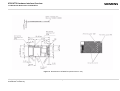
Dimensions of XT65/XT75 (all dimensions in mm)..................................................................... 45
Mating board-to-board connector 53748-0808 on application .................................................... 48
Molex board-to-board connector 52991-0808 on XT65/XT75 .................................................... 49
Mating board-to-board connector 53748-0808 on application .................................................... 50
Reference equipment for Type Approval .................................................................................... 51
XT65_XT75_HO_v00.130
Confidential / Preliminary
Page 5 of 58
2006-10-12
XT65/XT75 Hardware Interface Overview
1 Introduction
1
s
Introduction
This document applies to the following Siemens products:
•
•
XT65 Module
XT75 Module
The document describes the hardware of the XT65 and XT75 modules, both designed to connect to a cellular
device application and the air interface. It helps you quickly retrieve interface specifications, electrical and
mechanical details and information on the requirements to be considered for integrating further components.
The difference between both modules is that the XT75 additionally features EGPRS. Please note that except for
EGPRS specific statements, all information provided below applies to both module types.
Throughout the document, both modules are generally referred to as XT65/XT75.
1.1
Related Documents
[1] XT65 AT Command Set 00.130
[2]
[3]
[4]
[5]
[6]
[7]
[8]
[9]
[10]
[11]
[12]
[13]
[14]
[15]
[16]
[17]
XT75 AT Command Set 00.130
XT65/XT75 Release Notes 00.130
DSB75 Support Box - Evaluation Kit for Siemens Cellular Engines
Application Note 02: Audio Interface Design for GSM Applications
Application Note 07: Rechargeable Lithium Batteries in GSM Applications
Application Note 16: Upgrading Firmware
Application Note 17: Over-The-Air Firmware Update
Application Note 22: Using TTY / CTM Equipment
Application Note 24: Application Developer’s Guide
Application Note 26: Power Supply Design for GSM Applications
Application Note 32: Integrating USB into GSM Applications
Multiplexer User's Guide
Multiplex Driver Developer’s Guide for Windows 2000 and Windows XP
Multiplex Driver Installation Guide for Windows 2000 and Windows XP
Remote SAT User's Guide
Java User’s Guide
Java doc \wtk\doc\html\index.html
XT65_XT75_HO_v00.130
Confidential / Preliminary
Page 6 of 67
2006-10-12
XT65/XT75 Hardware Interface Overview
1.2 Terms and Abbreviations
1.2
s
Terms and Abbreviations
Abbreviation
Description
ADC
Analog-to-Digital Converter
AGC
Automatic Gain Control
ANSI
American National Standards Institute
ARFCN
Absolute Radio Frequency Channel Number
ARP
Antenna Reference Point
ASC0
Asynchronous Controller. Abbreviations used for the serial interface of XT65/XT75
B
Thermistor Constant
B2B
Board-to-board connector
BER
Bit Error Rate
BTS
Base Transceiver Station
CB or CBM
Cell Broadcast Message
CE
Conformité Européene (European Conformity)
CHAP
Challenge Handshake Authentication Protocol
CPU
Central Processing Unit
CS
Coding Scheme
CSD
Circuit Switched Data
CTS
Clear to Send
DAC
Digital-to-Analog Converter
DAI
Digital Audio Interface
dBm0
Digital level, 3.14dBm0 corresponds to full scale, see ITU G.711, A-law
DCE
Data Communication Equipment (typically modems, e.g. Siemens GSM engine)
DCS 1800
Digital Cellular System, also referred to as PCN
DRX
Discontinuous Reception
DSB
Development Support Box
DSP
Digital Signal Processor
DSR
Data Set Ready
DTE
Data Terminal Equipment (typically computer, terminal, printer or, for example, GSM application)
DTR
Data Terminal Ready
DTX
Discontinuous Transmission
EFR
Enhanced Full Rate
EGSM
Enhanced GSM
EIRP
Equivalent Isotropic Radiated Power
EMC
Electromagnetic Compatibility
ERP
Effective Radiated Power
XT65_XT75_HO_v00.130
Confidential / Preliminary
Page 7 of 67
2006-10-12
XT65/XT75 Hardware Interface Overview
1.2 Terms and Abbreviations
Abbreviation
Description
ESD
Electrostatic Discharge
ETS
European Telecommunication Standard
FCC
Federal Communications Commission (U.S.)
FDMA
Frequency Division Multiple Access
FR
Full Rate
GMSK
Gaussian Minimum Shift Keying
GPIO
General Purpose Input/Output
GPRS
General Packet Radio Service
GSM
Global Standard for Mobile Communications
HiZ
High Impedance
HR
Half Rate
I/O
Input/Output
IC
Integrated Circuit
IMEI
International Mobile Equipment Identity
ISO
International Standards Organization
ITU
International Telecommunications Union
kbps
kbits per second
LED
Light Emitting Diode
Li-Ion / Li+
Lithium-Ion
Li battery
Rechargeable Lithium Ion or Lithium Polymer battery
Mbps
Mbits per second
MMI
Man Machine Interface
MO
Mobile Originated
MS
Mobile Station (GSM engine), also referred to as TE
MSISDN
Mobile Station International ISDN number
MT
Mobile Terminated
NTC
Negative Temperature Coefficient
OEM
Original Equipment Manufacturer
PA
Power Amplifier
PAP
Password Authentication Protocol
PBCCH
Packet Switched Broadcast Control Channel
PCB
Printed Circuit Board
PCL
Power Control Level
PCM
Pulse Code Modulation
PCN
Personal Communications Network, also referred to as DCS 1800
PCS
Personal Communication System, also referred to as GSM 1900
PDU
Protocol Data Unit
XT65_XT75_HO_v00.130
Confidential / Preliminary
Page 8 of 67
s
2006-10-12
XT65/XT75 Hardware Interface Overview
1.2 Terms and Abbreviations
Abbreviation
Description
PLL
Phase Locked Loop
PPP
Point-to-point protocol
PSK
Phase Shift Keying
PSU
Power Supply Unit
R&TTE
Radio and Telecommunication Terminal Equipment
RAM
Random Access Memory
RF
Radio Frequency
RMS
Root Mean Square (value)
ROM
Read-only Memory
RTC
Real Time Clock
RTS
Request to Send
Rx
Receive Direction
SAR
Specific Absorption Rate
SELV
Safety Extra Low Voltage
SIM
Subscriber Identification Module
SMS
Short Message Service
SPI
Serial Peripheral Interface
SRAM
Static Random Access Memory
TA
Terminal adapter (e.g. GSM engine)
TDMA
Time Division Multiple Access
TE
Terminal Equipment, also referred to as DTE
Tx
Transmit Direction
UART
Universal asynchronous receiver-transmitter
URC
Unsolicited Result Code
USB
Universal Serial Bus
USSD
Unstructured Supplementary Service Data
VSWR
Voltage Standing Wave Ratio
s
Phonebook abbreviations
FD
SIM fixdialing phonebook
LD
SIM last dialing phonebook (list of numbers most recently dialed)
MC
Mobile Equipment list of unanswered MT calls (missed calls)
ME
Mobile Equipment phonebook
ON
Own numbers (MSISDNs) stored on SIM or ME
RC
Mobile Equipment list of received calls
SM
SIM phonebook
XT65_XT75_HO_v00.130
Confidential / Preliminary
Page 9 of 67
2006-10-12
XT65/XT75 Hardware Interface Overview
1.3 Regulatory and Type Approval Information
1.3
s
Regulatory and Type Approval Information
1.3.1
Directives and Standards
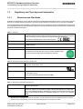
XT65/XT75 is designed to comply with the directives and standards listed below. Please note that the product is
still in a pre-release state and, therefore, type approval and testing procedures have not yet been completed.
It is the responsibility of the application manufacturer to ensure compliance of the final product with all provisions
of the applicable directives and standards as well as with the technical specifications provided in the "XT65/XT75
Hardware Interface Description".1
Table 1: Directives
99/05/EC
Directive of the European Parliament and of the council of 9 March 1999 on radio
equipment and telecommunications terminal equipment and the mutual recognition
of their conformity (in short referred to as R&TTE Directive 1999/5/EC).
The product is labeled with the CE conformity mark
89/336/EC
Directive on electromagnetic compatibility
73/23/EC
Directive on electrical equipment designed for use within certain voltage limits (Low
Voltage Directive)
95/94/EC
Automotive EMC directive
2002/95/EC
Directive of the European Parliament and of the Council of 27 January 2003 on the restriction of the use of certain hazardous substances in electrical and electronic equipment (RoHS)
Table 2: Standards of North American type approval
CFR Title 47
Code of Federal Regulations, Part 22 and Part 24 (Telecommunications, PCS); US
Equipment Authorization FCC
UL 60 950
Product Safety Certification (Safety requirements)
NAPRD.03 V3.6.1
Overview of PCS Type certification review board Mobile Equipment Type Certification and IMEI control
PCS Type Certification Review board (PTCRB)
RSS133 (Issue2)
Canadian Standard
Table 3: Standards of European type approval
3GPP TS 51.010-1
Digital cellular telecommunications system (Phase 2); Mobile Station (MS) conformance specification
ETSI EN 301 511 V9.0.2
Candidate Harmonized European Standard (Telecommunications series) Global
System for Mobile communications (GSM); Harmonized standard for mobile stations in the GSM 900 and DCS 1800 bands covering essential requirements under
article 3.2 of the R&TTE directive (1999/5/EC) (GSM 13.11 version 7.0.1 Release
1998)
1.
Manufacturers of applications which can be used in the US shall ensure that their applications have a PTCRB
approval. For this purpose they can refer to the PTCRB approval of the respective module.
XT65_XT75_HO_v00.130
Confidential / Preliminary
Page 10 of 67
2006-10-12
XT65/XT75 Hardware Interface Overview
1.3 Regulatory and Type Approval Information
s
Table 3: Standards of European type approval
GCF-CC V3.21.0
Global Certification Forum - Certification Criteria
ETSI EN 301 489-1
V1.4.1
Candidate Harmonized European Standard (Telecommunications series) Electro
Magnetic Compatibility and Radio spectrum Matters (ERM); Electro Magnetic
Compatibility (EMC) standard for radio equipment and services; Part 1: Common
Technical Requirements
ETSI EN 301 489-7
V1.2.1 (2000-09)
Candidate Harmonized European Standard (Telecommunications series) Electro
Magnetic Compatibility and Radio spectrum Matters (ERM); Electro Magnetic
Compatibility (EMC) standard for radio equipment and services; Part 7: Specific
conditions for mobile and portable radio and ancillary equipment of digital cellular
radio telecommunications systems (GSM and DCS)
IEC/EN 60950-1 (2001)
Safety of information technology equipment (2000)
Table 4: Requirements of quality
IEC 60068
Environmental testing
DIN EN 60529
IP codes
1.3.2
SAR requirements specific to portable mobiles
Mobile phones, PDAs or other portable transmitters and receivers incorporating a GSM module must be in accordance with the guidelines for human exposure to radio frequency energy. This requires the Specific Absorption
Rate (SAR) of portable XT65/XT75 based applications to be evaluated and approved for compliance with
national and/or international regulations.
Since the SAR value varies significantly with the individual product design manufacturers are advised to submit
their product for approval if designed for portable use. For European and US markets the relevant directives are
mentioned below. It is the responsibility of the manufacturer of the final product to verify whether or not further
standards, recommendations or directives are in force outside these areas.
Products intended for sale on US markets
ES 59005/ANSI C95.1 Considerations for evaluation of human exposure to Electromagnetic Fields (EMFs)
from Mobile Telecommunication Equipment (MTE) in the frequency range
30MHz - 6GHz
Products intended for sale on European markets
EN 50360
Product standard to demonstrate the compliance of mobile phones with the basic
restrictions related to human exposure to electromagnetic fields (300MHz - 3GHz)
IMPORTANT:
Manufacturers of portable applications based on XT65/XT75 modules are required to have their final product certified and apply for their own FCC Grant and Industry Canada Certificate related to the specific portable mobile.
See also Section 8.2.
XT65_XT75_HO_v00.130
Confidential / Preliminary
Page 11 of 67
2006-10-12
XT65/XT75 Hardware Interface Overview
1.3 Regulatory and Type Approval Information
1.3.3
s
SELV Requirements
The power supply connected to the XT65/XT75 module shall be in compliance with the SELV requirements
defined in EN 60950-1. See also Section 6.1 for further detail.
1.3.4
Safety Precautions
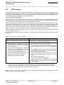
The following safety precautions must be observed during all phases of the operation, usage, service or repair
of any cellular terminal or mobile incorporating XT65/XT75. Manufacturers of the cellular terminal are advised to
convey the following safety information to users and operating personnel and to incorporate these guidelines into
all manuals supplied with the product. Failure to comply with these precautions violates safety standards of
design, manufacture and intended use of the product. Siemens AG assumes no liability for customer’s failure to
comply with these precautions.
When in a hospital or other health care facility, observe the restrictions on the use of mobiles.
Switch the cellular terminal or mobile off, if instructed to do so by the guidelines posted in sensitive areas. Medical equipment may be sensitive to RF energy.
The operation of cardiac pacemakers, other implanted medical equipment and hearing aids
can be affected by interference from cellular terminals or mobiles placed close to the device.
If in doubt about potential danger, contact the physician or the manufacturer of the device to
verify that the equipment is properly shielded. Pacemaker patients are advised to keep their
hand-held mobile away from the pacemaker, while it is on.
Switch off the cellular terminal or mobile before boarding an aircraft. Make sure it cannot be
switched on inadvertently. The operation of wireless appliances in an aircraft is forbidden to
prevent interference with communications systems. Failure to observe these instructions may
lead to the suspension or denial of cellular services to the offender, legal action, or both.
Do not operate the cellular terminal or mobile in the presence of flammable gases or fumes.
Switch off the cellular terminal when you are near petrol stations, fuel depots, chemical plants
or where blasting operations are in progress. Operation of any electrical equipment in potentially explosive atmospheres can constitute a safety hazard.
Your cellular terminal or mobile receives and transmits radio frequency energy while switched
on. Remember that interference can occur if it is used close to TV sets, radios, computers or
inadequately shielded equipment. Follow any special regulations and always switch off the
cellular terminal or mobile wherever forbidden, or when you suspect that it may cause interference or danger.
Road safety comes first! Do not use a hand-held cellular terminal or mobile when driving a
vehicle, unless it is securely mounted in a holder for speakerphone operation. Before making
a call with a hand-held terminal or mobile, park the vehicle.
Speakerphones must be installed by qualified personnel. Faulty installation or operation can
constitute a safety hazard.
XT65_XT75_HO_v00.130
Confidential / Preliminary
Page 12 of 67
2006-10-12
XT65/XT75 Hardware Interface Overview
1.3 Regulatory and Type Approval Information
s
IMPORTANT!
Cellular terminals or mobiles operate using radio signals and cellular networks. Because of
this, connection cannot be guaranteed at all times under all conditions. Therefore, you should
never rely solely upon any wireless device for essential communications, for example emergency calls.
Remember, in order to make or receive calls, the cellular terminal or mobile must be switched
on and in a service area with adequate cellular signal strength.
Some networks do not allow for emergency calls if certain network services or phone features
are in use (e.g. lock functions, fixed dialing etc.). You may need to deactivate those features
before you can make an emergency call.
Some networks require that a valid SIM card be properly inserted in the cellular terminal or
mobile.
Bear in mind that exposure to excessive levels of noise can cause physical damage to users!
With regard to acoustic shock, the cellular application must be designed to avoid unintentional
increase of amplification, e.g. for a highly sensitive earpiece. A protection circuit should be
implemented in the cellular application.
XT65_XT75_HO_v00.130
Confidential / Preliminary
Page 13 of 67
2006-10-12
XT65/XT75 Hardware Interface Overview
2 Product Concept
2
Product Concept
2.1
Key Features at a Glance
Feature
s
Implementation
General
Frequency bands
Quad band: GSM 850/900/1800/1900MHz
GSM class
Small MS
Output power (according to Class 4 (+33dBm ±2dB) for EGSM850
Release 99, V5)
Class 4 (+33dBm ±2dB) for EGSM900
Class 1 (+30dBm ±2dB) for GSM1800
Class 1 (+30dBm ±2dB) for GSM1900
XT75 only:
Class E2 (+27dBm ± 3dB) for GSM 850 8-PSK
Class E2 (+27dBm ± 3dB) for GSM 900 8-PSK
Class E2 (+26dBm +3 /-4dB) for GSM 1800 8-PSK
Class E2 (+26dBm +3 /-4dB) for GSM 1900 8-PSK
The values stated above are maximum limits. According to Release 99, the maximum output power in a multislot configuration may be lower. The nominal reduction of maximum output power varies with the number of uplink timeslots used
and amounts to 3.0dB for 2Tx, 4.8dB for 3Tx and 6.0dB for 4Tx.
Power supply
3.3V to 4.5V
Ambient operating
temperature according to
IEC 60068-2
Normal operation:
Physical
Dimensions: 34mm x 59mm x 3.5mm
-30°C to +65°C
Restricted operation:-30°C / +85°C
Weight: < 10g
RoHS
All hardware components fully compliant with EU RoHS Directive
GSM / GPRS / EGPRS features
Data transfer
GPRS:
Multislot Class 12
Full PBCCH support
Mobile Station Class B
Coding Scheme 1 – 4
EGPRS (XT75 only):
Multislot Class 10
Mobile Station Class B
Modulation and Coding Scheme MCS 1 – 9
CSD:
V.110, RLP, non-transparent
2.4, 4.8, 9.6, 14.4kbps
USSD
PPP-stack for GPRS data transfer
XT65_XT75_HO_v00.130
Confidential / Preliminary
Page 14 of 58
2006-10-12
XT65/XT75 Hardware Interface Overview
2.1 Key Features at a Glance
Feature
Implementation
SMS
Point-to-point MT and MO
s
Cell broadcast
Text and PDU mode
Storage: SIM card plus 25 SMS locations in mobile equipment
Transmission of SMS alternatively over CSD or GPRS. Preferred mode can be
user defined.
Fax
Group 3; Class 1
Audio
Speech codecs:
Half rate HR (ETS 06.20)
Full rate FR (ETS 06.10)
Enhanced full rate EFR (ETS 06.50/06.60/06.80)
Adaptive Multi Rate AMR
Speakerphone operation, echo cancellation, noise suppression, DTMF, 7 ringing
tones
GPS Features
Supported Protocol
NMEA-0183, RTCM v2.2, UBX binary protocol
GPS modes
GPS, Assisted GPS (AGPS), Differential GSP (DGPS), Satellite Based Augmentation Systems (SBAS)
Position accuracy
10-15m, with DGPS/SBAS 1-3m
Start-up times
Hot start < 3.5s
Warm start 33s, average
Cold start 34s, average
Sensitivity
Active antenna:
Aquisition sensitivity: -141dBm
Tracking sensitivity: -158dBm
At antenna connector:
Aquisition sensitivity: -139dBm
Tracking sensitivity: -156dBm
General
Receiver 16 channel, L1 1575.42 MHz, GPS part controlled by GSM baseband
controller, Java engine or via application (ASC0)
Software
AT commands
AT-Hayes GSM 07.05 and 07.07, Siemens
AT commands for RIL compatibility (NDIS/RIL)
TM
Microsoft
compatibility
Java platform
JDK Version: 1.4.2_09
RIL / NDIS for Pocket PC and Smartphone
Java Virtual Machine with APIs for AT Parser, Serial Interface, FlashFileSystem
and TCP/IP Stack.
Major benefits: seamless integration into Java applications, ease of programming, no need for application microcontroller, extremely cost-efficient hardware
and software design – ideal platform for industrial GSM applications.
The memory space available for Java programs is around 1.2 MB in the flash file
system and around 400kB RAM. Application code and data share the space in
the flash file system and in RAM.
XT65_XT75_HO_v00.130
Confidential / Preliminary
Page 15 of 58
2006-10-12
XT65/XT75 Hardware Interface Overview
2.1 Key Features at a Glance
s
Feature
Implementation
SIM Application Toolkit
SAT Release 99
TCP/IP stack
Access by AT commands
IP addresses
IP version 4
Remote SIM Access
XT65/XT75 supports Remote SIM Access. RSA enables XT65/XT75 to use a
remote SIM card via its serial interface and an external application, in addition to
the SIM card locally attached to the dedicated lines of the application interface.
The connection between the external application and the remote SIM card can be
a Bluetooth wireless link or a serial link.
The necessary protocols and procedures are implemented according to the “SIM
Access Profile Interoperability Specification of the Bluetooth Special Interest
Group”.
Firmware update
Generic update from host application over ASC0 or USB. Over-the-air (OTA)
firmware update is possible via SPI interface.
Interfaces
Serial interface (ASC0)
- 8-wire modem interface with status and control lines, unbalanced,
asynchronous
- Fixed bit rates: 300 bps to 460,800 bps
- Autobauding: 1,200 bps to 460,800 bps
- RTS0/CTS0 and XON/XOFF flow control.
- Multiplex ability according to GSM 07.10 Multiplexer Protocol.
USB
Supports a USB 2.0 Full Speed (12Mbit/s) slave interface.
I2C
I2C bus for 7-bit addressing and transmission rates up to 400kbps. Programmable with AT^SSPI command.
Alternatively, all pins of the I²C interface are configurable as SPI.
SPI
Serial Peripheral Interface for transmission rates up to 6.5 Mbps.
Programmable with AT^SSPI command.
If the SPI is active the I²C interface is not available.
Audio
2 analog interfaces (2 microphone inputs and 2 headphone outputs with microphone power supply)
1 digital interface (PCM)
SIM interface
Supported SIM cards: 3V, 1.8V
Antenna
•
•
Module interface
80-pin board-to-board connector
50Ohms. External GSM antenna can be connected via antenna connector.
50Ohms. External GPS antenna can be connected via antenna connector.
Power on/off, Reset
Power on/off
Switch-on by hardware pin IGT
Switch-off by AT command (AT^SMSO)
Automatic switch-off in case of critical temperature and voltage conditions.
Reset
Orderly shutdown and reset by AT command
Emergency reset by hardware pin EMERG_RST and IGT.
XT65_XT75_HO_v00.130
Confidential / Preliminary
Page 16 of 58
2006-10-12
XT65/XT75 Hardware Interface Overview
2.1 Key Features at a Glance
Feature
s
Implementation
Special features
Charging
Supports management of rechargeable Lithium Ion and Lithium Polymer batteries
Real time clock
Timer functions via AT commands
GPIO
10 I/O pins of the application interface programmable as GPIO.
Programming is done via AT commands.
Alternatively, GPIO pin10 is configurable as pulse counter.
Pulse counter
Pulse counter for measuring pulse rates from 0 to 1000 pulses per second.
If the pulse counter is active the GPIO10 pin is not available.
DAC output
Digital-to-Analog Converter which can provide a PWM signal.
Phonebook
SIM and phone
Evaluation kit
DSB75
XT65_XT75_HO_v00.130
Confidential / Preliminary
DSB75 Evaluation Board designed to test and type approve Siemens cellular
engines and provide a sample configuration for application engineering.
Page 17 of 58
2006-10-12
XT65/XT75 Hardware Interface Overview
3 Application Interface
3
s
Application Interface
XT65/XT75 is equipped with an 80-pin board-to-board connector that connects to the external application and
incorporates several sub-interfaces: power supply, charger interface, SIM interface, serial interface ASC0, serial
interface USB, serial interface I²C/SPI, two analog audio interfaces, digital audio interface (DAI), 10 lines GPIO
interface, as well as status and control lines: IGT, EMERG_RST, PWR_IND, SYNC (for details see Chapter 2
and Section 6.5).
XT65_XT75_HO_v00.130
Confidential / Preliminary
Page 18 of 67
2006-10-12
XT65/XT75 Hardware Interface Overview
3.1 Operating Modes
3.1
s
Operating Modes
The table below briefly summarizes the various operating modes available for the module.
Table 5: Overview of operating modes
Normal operation
GSM / GPRS SLEEP
Various power save modes set with AT+CFUN command.
Software is active to minimum extent. If the module was registered to the GSM network in IDLE mode, it is registered and paging with the BTS in SLEEP mode, too. Power saving can be
chosen at different levels: The NON-CYCLIC SLEEP mode
(AT+CFUN=0) disables the AT interface. The CYCLIC SLEEP
modes AT+CFUN=7 and 9 alternatingly activate and deactivate
the AT interfaces to allow permanent access to all AT commands.
POWER DOWN
GSM IDLE
Software is active. Once registered to the GSM network, paging
with BTS is carried out. The module is ready to send and receive.
GSM TALK
Connection between two subscribers is in progress. Power consumption depends on network coverage individual settings, such
as DTX off/on, FR/EFR/HR, hopping sequences, antenna.
GPRS IDLE
EGPRS IDLE
Module is ready for GPRS/EGPRS data transfer, but no data is
currently sent or received. Power consumption depends on network settings and GPRS/EGPRS configuration (e.g. multislot
settings).
GPRS DATA
EGPRS DATA
GPRS/EGPRS data transfer in progress. Power consumption
depends on network settings (e.g. power control level), uplink /
downlink data rates, GPRS configuration (e.g. used multislot settings) and reduction of maximum output power.
Normal shutdown after sending the AT^SMSO command.
Only a voltage regulator is active for powering the RTC. Software is not active. Interfaces
are not accessible. Operating voltage (connected to BATT+) remains applied.
Airplane mode
Airplane mode shuts down the radio part of the module, causes the module to log off from
the GSM/GPRS network and disables all AT commands whose execution requires a radio
connection.
Airplane mode can be controlled by using the AT commands AT^SCFG and AT+CALA:
•
•
•
With AT^SCFG=MEopMode/Airplane/OnStart the module can be configured to enter
the Airplane mode each time when switched on or reset.
The parameter AT^SCFG=MEopMode/Airplane can be used to switch back and forth
between Normal mode and Airplane mode any time during operation.
Setting an alarm time with AT+CALA followed by AT^SMSO wakes the module up into
Airplane mode at the scheduled time.
Charge-only mode Limited operation for battery powered applications. Enables charging while module is
detached from GSM network. Limited number of AT commands is accessible. Chargeonly mode applies when the charger is connected if the module was powered down with
AT^SMSO.
Charge mode during normal operation
Normal operation (SLEEP, IDLE, TALK, GPRS/EGPRS IDLE, GPRS/EGPRS DATA) and
charging running in parallel. Charge mode changes to Charge-only mode when the module is powered down before charging has been completed.
XT65_XT75_HO_v00.130
Confidential / Preliminary
Page 19 of 67
2006-10-12
s
XT65/XT75 Hardware Interface Overview
4 GSM Antenna Interface
4
GSM Antenna Interface
The GSM interface has an impedance of 50Ω. XT65/XT75 is capable of sustaining a total mismatch at the
antenna connector without any damage, even when transmitting at maximum RF power. DC electric strength is
given (see Table 11).
The external antenna must be matched properly to achieve best performance regarding radiated power, DCpower consumption, modulation accuracy and harmonic suppression. Antenna matching networks are not
included on the XT65/XT75 PCB and should be placed in the host application.
Regarding the return loss XT65/XT75 provides the following values in the active band:
Table 6: Return loss in the active band
State of module
Return loss of module
Recommended return loss of application
Receive
> 8dB
> 12dB
Transmit
not applicable
> 12dB
4.1
Antenna Installation
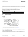
To suit the physical design of individual applications XT65/XT75 offers two alternative approaches to connecting
the antenna:
•
Recommended approach: U.FL-R-SMT antenna connector from Hirose assembled on the component side of
the PCB.
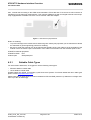
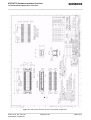
Figure 1: GSM antenna connector placement
See Section 4.3 for connector details.
•
Antenna pad and grounding plane placed on the bottom side. See Section 4.2.
The U.FL-R-SMT connector has been chosen as antenna reference point (ARP) for the Siemens reference
equipment submitted to type approve XT65/XT75. All RF data specified throughout this manual are related to the
ARP. For compliance with the test results of the Siemens type approval you are advised to give priority to the
connector, rather than using the antenna pad.
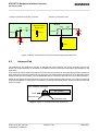
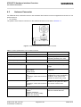
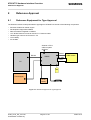
IMPORTANT: Both solutions can only be applied alternatively. This means, whenever an antenna is plugged to
the Hirose connector, the pad must not be used. Vice versa, if the antenna is connected to the pad, then the
Hirose connector must be left empty.
XT65_XT75_HO_v00.130
Confidential / Preliminary
Page 20 of 67
2006-10-12
s
XT65/XT75 Hardware Interface Overview
4.2 Antenna Pad
Antenna connected to Hirose connector:
Antenna or
Measurement
Equipment
Module
PAD
Antenna connected to pad:
U.FL
PAD
U.FL
50Ohm
50Ohm
50Ohm
Module
Z
Antenna
Z
50Ohm
Figure 40: Never use antenna connector and antenna pad at the same time
4.2
Antenna Pad
The antenna can be soldered to the pad, or attached via contact springs. For proper grounding connect the
antenna to the ground plane on the bottom of XT65/XT75 which must be connected to the ground plane of the
application.
If you decide to use the antenna pad take into account that the pad has not been intended as antenna reference
point (ARP) for the Siemens XT65/XT75 type approval. The antenna pad is provided only as an alternative option
which can be used, for example, if the recommended Hirose connection does not fit into your antenna design.
Please ensure that the antenna pad does not come into contact with the holding device or any other components
of the host application. It needs to be surrounded by a restricted area filled with air, which must also be reserved
0.8mm in height.
U.FL antenna connector
RF section
PCB
Antenna pad
Restricted area
Figure 2: Figure 41: Restricted area around antenna pad
XT65_XT75_HO_v00.130
Confidential / Preliminary
Page 21 of 67
2006-10-12
XT65/XT75 Hardware Interface Overview
4.2 Antenna Pad
s
Also, consider that according to the GSM recommendations TS 45.005 and TS 51.010-01 a 50Ω connector is
mandatory for type approval measurements. This requires GSM devices with an integral antenna to be temporarily equipped with a suitable connector or a low loss RF cable with adapter.
Figure 3: GSM antenna pad placement
Notes on soldering:
•
•
To prevent damage to the module and to obtain long-term solder joint properties you are advised to maintain
the standards of good engineering practice for soldering.
Be sure to solder the antenna core to the pad and the shielding of the coax cable to the ground plane of the
module next to the antenna pad. The direction of the cable is not relevant from the electrical point of view.
XT65/XT75 material properties:
XT65/XT75 PCB:
FR4
Antenna pad:
Gold plated pad
4.2.1
Suitable Cable Types
For direct solder attachment, we suggest to use the following cable types:
•
•
RG316/U 50Ohm coaxial cable
1671A 50Ohm coaxial cable
Suitable cables are offered, for example, by IMS Connector Systems. For further details and other cable types
please contact http://www.imscs.com.
Please note that the GSM antenna must be isolated for ESD and SAR protection (to withstand a voltage resistance up to 8kV air discharge).
XT65_XT75_HO_v00.130
Confidential / Preliminary
Page 22 of 67
2006-10-12
s
XT65/XT75 Hardware Interface Overview
4.3 Antenna Connector
4.3
Antenna Connector
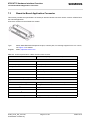
For GSM and GPS, XT65/XT75 uses an ultra-miniature SMT antenna connector supplied from Hirose Ltd. The
product name is:
•
U.FL-R-SMT
The position of the antenna connector on the XT65/XT75 board can be seen in Section 4.1.
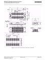
Figure 4: Mechanical dimensions of U.FL-R-SMT connector
Table 7: Product specifications of U.FL-R-SMT connector
Item
Specification
Conditions
Nominal impedance
50Ω
Operating temp:-40°C to + 90°C
Operating humidity: max. 90%
Rated frequency
DC to 3GHz
Ratings
Mechanical characteristics
Female contact holding force 0.15N min
Measured with a ; 0.475 pin
gauge
Repetitive operation
Contact resistance:
Center 25mΩ
Outside 15mΩ
30 cycles of insertion and disengagement
Vibration
No momentary disconnections of
1µs;
No damage, cracks and looseness
of parts
Frequency of 10 to 100Hz, single
amplitude of 1.5mm, acceleration
of 59m/s2, for 5 cycles in the
direction of each of the 3 axes
Shock
No momentary disconnections of
1µs.
No damage, cracks and looseness
of parts.
Acceleration of 735m/s2, 11ms
duration for 6 cycles in the direction of each of the 3 axes
No damage, cracks and looseness
of parts.
Insulation resistance:
100MΩ min. at high humidity
500MΩ min. when dry
Exposure to 40°C, humidity of
95% for a total of 96 hours
Environmental characteristics
Humidity resistance
XT65_XT75_HO_v00.130
Confidential / Preliminary
Page 23 of 67
2006-10-12
s
XT65/XT75 Hardware Interface Overview
4.3 Antenna Connector
Table 7: Product specifications of U.FL-R-SMT connector
Item
Specification
Conditions
Temperature cycle
No damage, cracks and looseness
of parts.
Contact resistance:
Center 25mΩ
Outside 15mΩ
Temperature: +40°C → 5 to 35°C
→ +90°C → 5 to 35°C
Time: 30min → within 5min →
30min within 5min
Salt spray test
No excessive corrosion
48 hours continuous exposure to
5% salt water
Table 8: Material and finish of U.FL-R-SMT connector and recommended plugs
Part
Material
Finish
Shell
Phosphor bronze
Silver plating
Male center contact
Brass
Gold plating
Female center contact
Phosphor bronze
Gold plating
Insulator
Plug: PBT
Receptacle: LCP
Black
Beige
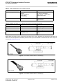
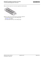
Mating plugs and cables can be chosen from the Hirose U.FL Series. Examples are shown below and listed in
Table 19. For latest product information please contact your Hirose dealer or visit the Hirose home page, for
example http://www.hirose.com.
Figure 5: U.FL-R-SMT connector with U.FL-LP-040 plug
Figure 6: U.FL-R-SMT connector with U.FL-LP-066 plug
XT65_XT75_HO_v00.130
Confidential / Preliminary
Page 24 of 67
2006-10-12
XT65/XT75 Hardware Interface Overview
4.3 Antenna Connector
s
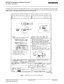
In addition to the connectors illustrated above, the U.FL-LP-(V)-040(01) version is offered as an extremely space
saving solution. This plug is intended for use with extra fine cable (up to ; 0.81mm) and minimizes the mating
height to 2mm. See Figure 46 which shows the Hirose datasheet.
Figure 7: Specifications of U.FL-LP-(V)-040(01) plug
XT65_XT75_HO_v00.130
Confidential / Preliminary
Page 25 of 67
2006-10-12
s
XT65/XT75 Hardware Interface Overview
4.3 Antenna Connector
Table 9: Ordering information for Hirose U.FL Series
Item
Part number
HRS number
Connector on XT65/XT75
U.FL-R-SMT
CL331-0471-0-10
Right-angle plug shell for
; 0.81mm cable
U.FL-LP-040
CL331-0451-2
Right-angle plug for
; 0.81mm cable
U.FL-LP(V)-040 (01)
CL331-053-8-01
Right-angle plug for
; 1.13mm cable
U.FL-LP-068
CL331-0452-5
Right-angle plug for
; 1.32mm cable
U.FL-LP-066
CL331-0452-5
Extraction jig
E.FL-LP-N
CL331-04441-9
XT65_XT75_HO_v00.130
Confidential / Preliminary
Page 26 of 67
2006-10-12
XT65/XT75 Hardware Interface Overview
5 GPS Antenna Interface
5
s
GPS Antenna Interface
In order to receive satellite signals an additional GPS antenna must be connected to the GPS part of the XT65/
XT75 module.
5.1
Antenna Installation
To suit the physical design of individual applications XT65/XT75 offers two alternative approaches to connecting
the antenna:
•
Recommended approach: U.FL-R-SMT antenna connector from Hirose assembled on the component side of
the PCB. The GPS antenna connector is the same as for the GSM antenna connector. For details see Section
5.3.
Figure 8: GPS antenna connector placement
•
Antenna pad and grounding plane placed on the bottom side of the PCB. For some notes on soldering the
antenna to the pad see Section 5.2.
Figure 9: GPS antenna pad placement
Note that it is not possible to employ both alternatives at the same time.
XT65_XT75_HO_v00.130
Confidential / Preliminary
Page 27 of 67
2006-10-12
s
XT65/XT75 Hardware Interface Overview
5.2 GPS Antenna
5.2
GPS Antenna
It is possible to connect active or passive GPS antennas. In either case they must have 50 Ohm impedance. The
application should be designed in a way to achieve a minimum of 6dB decoupling between the GSM/DCS/PCS
antenna path and the GPS antenna path. Please note that the GPS antenna must be isolated for ESD protection
(to withstand a voltage resistance up to 8kV air discharge).
Active versus Passive Antennas
Passive antennas contain only the radiating element, e.g. the ceramic patch or the quadrifilar dipole structure.
Sometimes they also contain a passive matching network to match the electrical connection to 50 Ohms impedance. Note: Passive antenna need not have a DC connection to ground.
Active antennas have an integrated low-noise amplifier (in some cases an additional GPS band pass filter). This
is beneficial in two respects: First, the losses of the cable do no longer influence the overall noise figure of the
GPS receiver system. Secondly, even the receiver noise figure can be higher without sacrificing performance.
Active antennas need a power supply that will contribute to GPS system power consumption, typically in the
region of 5 to 20 mA. The supply voltage is fed to the antenna through the coaxial RF cable.
Inside the antenna, the DC component on the inner conductor will be separated from the RF signal and routed
to the supply pin of the LNA.
The use of an active antenna is always advisable, if the RF-cable length between receiver and antenna exceeds
about 10 cm.
Table 10: GPS antenna: Active versus Passive
Active Antenna
Passive Antenna
Active antenna connected to the GPS module.
Passive patch antennas or quadrifilar dipole antennas connected with a microcoax to the GPS module
•
•
•
•
•
•
A wide range of active patch or quadrifilar
dipole antennas is available in the market.
They differ in size, sensitivity, selectivity and
power consumption
Less sensitive to jamming than a passive
antenna, as the placement of the active
antenna is usually some distance away of
other noise or signal radiating devices.
Needs more power than a passive antenna
Easier and less sensitive to jamming.
More freedom to place the antenna1
1.
•
•
•
•
•
•
Passive patch antennas or helical antennas are available in different form factors and sensitivity
Antenna must be connected with a low insertion loss
line to the GPS module to ensure a good GPS sensitivity.
The PCB design with a passive antenna must consider
the sensitivity of the GPS antenna to other radiating circuits or general signal jamming.
Due to the proximity of the GPS antenna to other electronic circuits, in-band jamming may become a critical
issue.
Only suitable for RF experts!
Needs more experience in RF design.
Requires more effort to optimise the circuit design to
minimize jamming into the antenna and the antenna
signal routing.
Some cars for instance have a metallic coating on the windshield. GPS reception may not be possible in such a
car. There is usually a small section, typically behind the rear view mirror without the coating for mobile phone
and GPS antennas. The antenna has to be placed with optimal sky visibility. An external antenna (e.g. with a
magnetic base) is easier to use and usually allows a better positioning.
Note: If you are not an expert in RF designs, you should implement an active antenna setup and place the
antenna away from any emitting circuits.
XT65_XT75_HO_v00.130
Confidential / Preliminary
Page 28 of 67
2006-10-12
s
XT65/XT75 Hardware Interface Overview
6 Electrical, Reliability and Radio Characteristics
6
Electrical, Reliability and Radio Characteristics
6.1
Absolute Maximum Ratings
The absolute maximum ratings stated in Table 11 are stress ratings under any conditions. Stresses beyond any
of these limits will cause permanent damage to XT65/XT75.
The power supply connected to the XT65/XT75 module shall be compliant with the SELV requirements defined
in EN60950. Above all, the peak current of the power supply shall be limited according to Table 11.
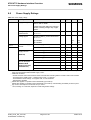
Table 11: Absolute maximum ratings
Parameter
Min
Peak current of power supply
Max
Unit
3.2
A
Supply voltage BATT+
-0.3
5.5
V
Voltage at digital pins in POWER DOWN mode
-0.3
0.3
V
Voltage at digital pins in normal operation
-0.3
3.05
or VEXT+0.3
V
Voltage at analog pins in POWER DOWN mode
-0.3
0.3
V
1
Voltage at analog pins, VMIC on
-0.3
2.75
V
Voltage at analog pins, VMIC off1
-0.3
0.3
V
Voltage at VCHARGE pin
-0.3
5.5
V
Voltage at CHARGEGATE pin
-0.3
5.5
V
VUSB_IN
-0.3
5.5
V
USB_DP, USB_DN
-0.3
3.5
V
VSENSE
5.5
V
ISENSE
5.5
V
PWR_IND
-0.3
510
V
VDDLP
-0.3
5.5
V
GSM antenna
-36
36
V
GPS antenna
-0.3
VBATT++0.3
V
1.
For normal operation the voltage at analog pins with VMIC on should be within the range of 0V to 2.4V
and with VMIC off within the range of -0.25V to 0.25V.
XT65_XT75_HO_v00.130
Confidential / Preliminary
Page 29 of 67
2006-10-12
s
XT65/XT75 Hardware Interface Overview
6.2 Operating Temperatures
6.2
Operating Temperatures
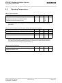
Table 12: Board temperature
Parameter
Min
Typ
Max
Unit
Temperature measured on XT65/XT75 board
-30
---
>+80
°C
Temperature measured at battery NTC
-20
---
+60
Automatic shutdown1
1.
Due to temperature measurement uncertainty, a tolerance on the stated shutdown thresholds may occur.
The possible deviation is in the range of ± 3°C at the overtemperature limit and ± 5°C at the undertemperature limit.
Table 13: Ambient temperature according to IEC 60068-2 (without forced air circulation)
Parameter
Min
Typ
Max
Unit
Operating temperature range
-30
+25
+65
°C
+70
°C
+70 to
°C
Restricted operation (with VBATT ≤ 3,8V)
1
Restricted operation
---
+85
1.
Restricted operation allows normal mode speech calls or data transmission for limited time until automatic
thermal shutdown takes effect. For operating the XT75/65 above an expected ambient temperatures of
75°C please contact Siemens Application Engineering. The duration of emergency calls is unlimited because automatic thermal shutdown is deferred until hang up.
Table 14: Charging temperature
Parameter
Min
Typ
Max
Unit
Battery temperature for software controlled fast charging
(measured at battery NTC)
0
---
+45
°C
XT65_XT75_HO_v00.130
Confidential / Preliminary
Page 30 of 67
2006-10-12
s
XT65/XT75 Hardware Interface Overview
6.3 Storage Conditions
6.3
Storage Conditions
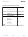
The conditions stated below are only valid for modules in their original packed state in weather protected, nontemperature-controlled storage locations. Normal storage time under these conditions is 12 months maximum.
Table 15: Storage conditions
Type
Condition
Unit
Reference
Air temperature: Low
-40
°C
ETS 300 019-2-1: T1.2, IEC 68-2-1 Ab
High
+85
Humidity relative: Low
Air pressure:
ETS 300 019-2-1: T1.2, IEC 68-2-2 Bb
10
%
---
High
90 at 30°C
ETS 300 019-2-1: T1.2, IEC 68-2-56 Cb
Condens.
90-100 at 30°C
ETS 300 019-2-1: T1.2, IEC 68-2-30 Db
Low
70
High
106
kPa
IEC TR 60271-3-1: 1K4
IEC TR 60271-3-1: 1K4
Movement of surrounding air
1.0
m/s
IEC TR 60271-3-1: 1K4
Water: rain, dripping, icing and
frosting
Not allowed
---
---
Radiation:
Solar
1120
W/m2
ETS 300 019-2-1: T1.2, IEC 68-2-2 Bb
Heat
600
ETS 300 019-2-1: T1.2, IEC 68-2-2 Bb
Chemically active substances
Not recommended
IEC TR 60271-3-1: 1C1L
Mechanically active substances
Not recommended
IEC TR 60271-3-1: 1S1
IEC TR 60271-3-1: 1M2
Vibration sinusoidal:
Displacement
1.5
mm
Acceleration
5
m/s2
Frequency range
2-9 9-200
Hz
Shocks:
IEC 68-2-27 Ea
Shock spectrum
semi-sinusoidal
Duration
1
ms
Acceleration
50
m/s2
XT65_XT75_HO_v00.130
Confidential / Preliminary
Page 31 of 67
2006-10-12
s
XT65/XT75 Hardware Interface Overview
6.4 Reliability Characteristics
6.4
Reliability Characteristics
The test conditions stated below are an extract of the complete test specifications.
Table 16: Summary of reliability test conditions
Type of test
Conditions
Standard
Vibration
Frequency range: 10-20Hz; acceleration: 3.1mm
amplitude
DIN IEC 68-2-6
Frequency range: 20-500Hz; acceleration: 5g
Duration: 2h per axis = 10 cycles; 3 axes
Shock half-sinus
DIN IEC 68-2-27
Acceleration: 500g
Shock duration: 1msec
1 shock per axis
6 positions (± x, y and z)
Dry heat
EN 60068-2-2 Bb
ETS 300 019-2-7
Temperature: +70 ±2×C
Test duration: 16h
Humidity in the test chamber: < 50%
Temperature
change (shock)
Low temperature: -40×C ±2×C
DIN IEC 68-2-14 Na
High temperature: +85×C ±2×C
Changeover time: < 30s (dual chamber system)
ETS 300 019-2-7
Test duration: 1h
Number of repetitions: 100
Damp heat cyclic
High temperature: +55×C ±2×C
DIN IEC 68-2-30 Db
Low temperature: +25×C ±2×C
Humidity: 93% ±3%
ETS 300 019-2-5
Number of repetitions: 6
Test duration: 12h + 12h
Cold (constant
exposure)
Temperature: -40 ±2×C
DIN IEC 68-2-1
Test duration: 16h
XT65_XT75_HO_v00.130
Confidential / Preliminary
Page 32 of 67
2006-10-12
s
XT65/XT75 Hardware Interface Overview
6.5 Pin Assignment and Signal Description
6.5
Pin Assignment and Signal Description
The Molex board-to-board connector on XT65/XT75 is an 80-pin double-row receptacle. The position of the
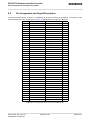
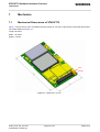
board-to-board connector can be seen in Figure 11 that shows the top view of XT65/XT75.
1
2
3
4
5
6
7
8
9
10
11
12
13
14
15
16
17
18
19
20
21
22
23
24
25
26
27
28
29
30
31
32
33
34
35
36
37
38
39
40
GND
ADC1_IN
ADC2_IN
GND
GPIO10
GPIO8
SPIDI
GPIO7
GPIO6
GPIO5
I2CCLK_SPICLK
VUSB_IN
DAI5
ISENSE
DAI6
CCCLK
CCVCC
CCIO
CCRST
CCIN
CCGND
DAI4
DAI3
DAI2
DAI1
DAI0
BATT_TEMP
SYNC
not connected
RXD0
Pull up
TXD0
VDDLP
VCHARGE
CHARGEGATE
GND
GND
GND
GND
GND
GND
DAC_OUT
PWR_IND
Do not use
GPIO9
SPICS
GPIO4
GPIO3
GPIO2
GPIO1
I2CDAT_SPIDO
USB_DP
USB_DN
VSENSE
VMIC
EPN2
EPP2
EPP1
EPN1
MICN2
MICP2
MICP1
MICN1
AGND
IGT
EMERG_RST
DCD0
not connected
CTS0
Pull up
DTR0
RTS0
DSR0
RING0
VEXT
BATT+
BATT+
BATT+
BATT+
BATT+
80
79
78
77
76
75
74
73
72
71
70
69
68
67
66
65
64
63
62
61
60
59
58
57
56
55
54
53
52
51
50
49
48
47
46
45
44
43
42
41
Figure 10: Pin assignment (component side of XT65/XT75)
XT65_XT75_HO_v00.130
Confidential / Preliminary
Page 33 of 67
2006-10-12
s
XT65/XT75 Hardware Interface Overview
6.5 Pin Assignment and Signal Description
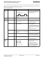
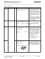
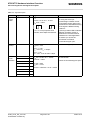
Please note that the reference voltages listed in Table 17 are the values measured directly on the XT65/XT75
module. They do not apply to the accessories connected.
Table 17: Signal description
Function
Signal name
IO
Signal form and level
Comment
Power
supply
BATT+
I
VI = 3.3V to 4.5V
Five pins of BATT+ and GND must
be connected in parallel for supply
purposes because higher peak
currents may occur.
VItyp = 3.8V
I ≈ 2A, during Tx burst
n Tx = n x 577µs peak current every
4.616ms
Power
supply
GND
Charge
Interface
VCHARGE
I
Ground
Application Ground
VImin = 3.1 V
This line signalizes to the processor that the charger is connected.
VImax = 5.25V
BATT_TEMP
I
Connect NTC with RNTC ≈ 10kΩ @
25°C to ground.
If unused keep pin open.
Battery temperature measurement
via NTC resistance.
NTC should be installed inside or
near battery pack to enable proper
charging and deliver temperature
values.
If unused keep pin open.
ISENSE
I
VImax = 4.65V
ΔVImax to VBATT+ = +0.3V at normal
condition
Connect ISENSE directly at the
shunt for current measurement.
If unused connect pin to VSENSE.
VSENSE
I
VImax = 4.5V
VSENSE must be directly connected to BATT+ at battery connector or external power supply.
CHARGEGATE
O
VImax = 5.5V
IImax = 0.6mA (for fast charging)
Control line to the gate of charge
FET
If unused keep pin open.
External
supply
voltage
VEXT
O
Normal mode:
VOmin = 2.75V
VOtyp = 2.93V
VOmax = 3.05V
IOmax = -50mA
Cload,max,extern = 1µF
XT65_XT75_HO_v00.130
Confidential / Preliminary
Page 34 of 67
VEXT may be used for application
circuits, for example to supply
power for an I2C.
If unused keep pin open.
Not available in Power-down
mode. The external digital logic
must not cause any spikes or
glitches on voltage VEXT.
2006-10-12
s
XT65/XT75 Hardware Interface Overview
6.5 Pin Assignment and Signal Description
Table 17: Signal description
Function
Signal name
IO
Signal form and level
Comment
Power
indicator
PWR_IND
O
VIHmax = 10V
PWR_IND (Power Indicator) notifies the module’s on/off state.
VOLmax = 0.4V at Imax = 2mA
PWR_IND is an open collector
that needs to be connected to an
external pull-up resistor. Low state
of the open collector indicates that
the module is on. Vice versa, high
level notifies the Power-down
mode.
Therefore, the pin may be used to
enable external voltage regulators
which supply an external logic for
communication with the module,
e.g. level converters.
Ignition
IGT
I
Internal pull-up: RI ≈ 30kΩ, CI ≈ 10nF
VILmax = 0.8V at Imax = -150µA
VOHmax = VBATT+
This signal switches the mobile
on.
Internal pull-up: RI ≈ 5kΩ
VILmax = 0.2V at Imax = -0.5mA
VOHmin = 1.75V
Reset or shut down in case of
emergency: Pull down and release
EMERG_RST. Then, activating
IGT for 400ms will reset XT65/
XT75. If IGT is not activated for
400ms, XT65/XT75 switches off.
This line must be driven low by an
ON ~~~|____|~~~ Active Low ≥ 300ms open drain or open collector
driver.
Emergency
reset
EMERG_RST
I
VOHmax = 3.05V
Signal
10ms
|______|~~~ Pull down ≥
~~~
Data stored in the volatile memory
will be lost. For orderly software
controlled reset rather use the
AT+CFUN command (e.g.
AT+CFUN=x,1).
This line must be driven by open
drain or open collector.
If unused keep pin open.
Power-on
reset
O
Internal pull-up: RI ≈ 5kΩ
VOLmax = 0.2V at I = 2mA
VOHmin = 1.75V
VOHmax = 3.05V
Reset signal driven by the module
which can be used to reset any
application or device connected to
the module. Only effective for
120ms during the assertion of IGT
when the module is about to start.
Reset signal driven by the module:
VEXT
EMRG_RST
appr. 120ms
XT65_XT75_HO_v00.130
Confidential / Preliminary
Page 35 of 67
2006-10-12
s
XT65/XT75 Hardware Interface Overview
6.5 Pin Assignment and Signal Description
Table 17: Signal description
Function
Signal name
IO
Signal form and level
Comment
Synchronization
SYNC
O
VOLmax = 0.3V at I = 0.1mA
There are two alternative options
for using the SYNC pin:
VOHmin = 2.3V at I = -0.1mA
VOHmax = 3.05V
n Tx = n x 577µs impulse each
4.616ms, with 180µs forward time.
a) Indicating increased current
consumption during uplink transmission burst. Note that the timing
of the signal is different during
handover.
b) Driving a status LED to indicate
different operating modes of
XT65/XT75. The LED must be
installed in the host application.
To select a) or b) use the
AT^SSYNC command.
If unused keep pin open.
RTC
backup
VDDLP
I/O
RI ≈ 1kΩ
VOmax = 4.5V
If unused keep pin open.
VBATT+ = 4.2V:
VO = 3.3V at IO = -500µA
VBATT+ = 0V:
VI = 2.4V…4.5V at Imax = 25µA
ASC0
RXD0
O
Serial
interface
TXD0
I
CTS0
O
RTS0
I
DTR0
I
DCD0
O
DSR0
O
RING0
O
XT65_XT75_HO_v00.130
Confidential / Preliminary
VOLmax = 0.2V at I = 2mA
VOHmin = 2.55V at I = -0.5mA
VOHmax = 3.05V
Serial interface for AT commands
or data stream.
If lines are unused keep pins open.
VILmax = 0.8V
VIHmin = 2.15V
VIHmax = VEXTmin + 0.3V = 3.05V
Page 36 of 67
2006-10-12
s
XT65/XT75 Hardware Interface Overview
6.5 Pin Assignment and Signal Description
Table 17: Signal description
Function
Signal name
IO
Signal form and level
Comment
SIM
interface
specified
for use
with 3V
SIM card
CCIN
I
RI ≈ 100kΩ
VILmax = 0.6V at I = -25µA
VIHmin = 2.1V at I = -10µA
VOmax = 3.05V
CCIN = Low, SIM card holder
closed
CCRST
O
RO ≈ 47Ω
VOLmax = 0.25V at I = +1mA
VOHmin = 2.5V at I = -0.5mA
VOHmax = 2.95V
CCIO
I/O
RI ≈ 4.7kΩ
VILmax = 0.75V
VILmin = -0.3V
VIHmin = 2.1V
VIHmax = CCVCCmin + 0.3V =
3.05V
Maximum cable length or copper
track 100mm to SIM card holder.
All signals of SIM interface are
protected against ESD with a special diode array.
Usage of CCGND is mandatory.
RO ≈ 100Ω
VOLmax = 0.3V at I = +1mA
VOHmin = 2.5V at I = -0.5mA
VOHmax = 2.95V
CCCLK
O
RO ≈ 100Ω
VOLmax = 0.3V at I = +1mA
VOHmin = 2.5V at I = -0.5mA
VOHmax = 2.95V
CCVCC
O
VOmin = 2.75V
VOtyp = 2.85V
VOmax = 2.95V
IOmax = -20mA
CCGND
XT65_XT75_HO_v00.130
Confidential / Preliminary
Ground
Page 37 of 67
2006-10-12
s
XT65/XT75 Hardware Interface Overview
6.5 Pin Assignment and Signal Description
Table 17: Signal description
Function
Signal name
IO
Signal form and level
Comment
SIM
interface
specified
for use
with 1.8V
SIM card
CCIN
I
RI ≈ 100kΩ
VILmax = 0.6V at I = -25µA
VIHmin = 2.1V at I = -10µA
VOmax = 3.05V
CCIN = Low, SIM card holder
closed
CCRST
O
RO ≈ 47Ω
VOLmax = 0.25V at I = +1mA
VOHmin = 1.45V at I = -0.5mA
VOHmax = 1.90V
CCIO
I/O
RI ≈ 4.7kΩ
VILmax = 0.45V
VIHmin = 1.35V
VIHmax = CCVCCmin + 0.3V =
2.00V
Maximum cable length or copper
track 100mm to SIM card holder.
All signals of SIM interface are
protected against ESD with a special diode array.
Usage of CCGND is mandatory.
RO ≈ 100Ω
VOLmax = 0.3V at I = +1mA
VOHmin = 1.45V at I = -0.5mA
VOHmax = 1.90V
CCCLK
O
RO ≈ 100Ω
VOLmax = 0.3V at I = +1mA
VOHmin = 1.45V at I = -0.5mA
VOHmax = 1.90V
CCVCC
O
VOmin = 1.70V,
VOtyp = 1.80V
VOmax = 1.90V
IOmax = -20mA
CCGND
I2C interface
Ground
I2CCLK
_SPICLK
O
VOLmax = 0.2V at I = 2mA
VOHmin = 2.55V at I = -0.5mA
VOHmax = 3.05V
I2C interface is only available if the
two pins are not used as SPI interface.
I2CDAT_SPIDO
I/O
VOLmax = 0.2V at I = 2mA
VILmax = 0.8V
VIHmin = 2.15V
I2CDAT is configured as Open
Drain and needs a pull-up resistor
in the host application.
VIHmax = VEXTmin + 0.3V = 3.05V
According to the I2C Bus Specification Version 2.1 for the fast
mode a rise time of max. 300ns is
permitted. There is also a maximum VOL=0.4V at 3mA specified.
The value of the pull-up depends
on the capacitive load of the whole
system (I2C Slave + lines). The
maximum sink current of I2CDAT
and I2CCLK is 4mA.
If lines are unused keep pins open.
XT65_XT75_HO_v00.130
Confidential / Preliminary
Page 38 of 67
2006-10-12
s
XT65/XT75 Hardware Interface Overview
6.5 Pin Assignment and Signal Description
Table 17: Signal description
Function
Signal name
IO
Signal form and level
Comment
SPI
SPIDI
I
Serial
Peripheral Interface
I2CDAT_SPIDO
O
VOLmax = 0.2V at I = 2mA
VOHmin = 2.55V at I = -0.5mA
VOHmax = 3.05V
If the Serial Peripheral Interface is
active the I2C interface is not available.
SPICS
O
VILmax = 0.8V
VIHmin = 2.15V,
VIHmax = VEXTmin + 0.3V = 3.05V
USB
VUSB_IN
I
VINmin = 4.0V
VINmax = 5.25V
USB_DN
I/O
USB_DP
I/O
Differential Output Crossover voltage Range
VCRSmin = 1.5V, VCRSmax = 2.0V
I2CCLK_SPICLK O
Driver Output Resistance
ZDRVtyp = 32Ohm
Digital
Audio
interface
DAI0 (USC0)
I/O
DAI1 (USC1)
I/O
DAI2 (USC2)
I/O
DAI3 (USC3)
I/O
DAI4 (USC4)
I/O
DAI5 (USC5)
I/O
DAI6 (USC6)
I/O
GPIO1
General
Purpose
Input/Out- GPIO2
put
GPIO3
I/O
I/O
I/O
GPIO5
I/O
GPIO6
I/O
GPIO7
I/O
GPIO8
I/O
GPIO9
I/O
GPIO10
I/O
All electrical characteristics
according to USB Implementers’
Forum, USB 2.0 Full Speed Specification.
Without Java: USB port
Under Java: Debug interface for
development purposes.
If lines are unused keep pins open.
DAI0…DAI6 are configurable as
PCM interface
VILmax = 0.8V
VIHmin = 2.15V
VIHmax = VEXTmin + 0.3V = 3.05V
VOLmax = 0.2V at I = 2mA
VOHmin = 2.55V at I = -0.5mA
VOHmax = 3.05V
I/O
GPIO4
XT65_XT75_HO_v00.130
Confidential / Preliminary
VOLmax = 0.2V at I = 2mA
VOHmin = 2.55V at I = -0.5mA
VOHmax = 3.05V
If lines are unused keep pins open.
VILmax = 0.8V
VIHmin = 2.15V,
VIHmax = VEXTmin + 0.3V = 3.05V
Page 39 of 67
All pins which are configured as
input must be connected to a pullup or pull-down resistor.
If lines are unused (not configured) keep pins open.
Alternatively, the GPIO10 pin can
be configured as a pulse counter
for pulse rates from 0 to 1000
pulses per second.
2006-10-12
s
XT65/XT75 Hardware Interface Overview
6.5 Pin Assignment and Signal Description
Table 17: Signal description
Function
Signal name
Analog
ADC1_IN
Digital
Converter ADC2_IN
IO
Signal form and level
Comment
I
Input voltage: VImin = 0V, VImax =
2.4V
Inputs used for measuring external voltages. In the range of 0mV
to 2400mV.
I
Ri ≈ 750kOhms Measurement interUse the command AT^SRADC to
val: 100ms - 30s selectable by AT
select analog inputs ADC1_IN or
command
ADC2_IN, to set the measurement
Sensitivity, accuracy: 2400 steps
mode and read out the results.
(1step = 1mv)
The values are indicated in mV.
Cut-off frequency: 30 Hz
ADC1_IN and ADC2_IN are internally multiplexed through analog
Underflow: ≥ -25mV
switch.
Overflow: ≥ +2425 mV
Important:
Accuracy: ± 0.5mV
For restrictions during SLEEP
Linear error: ± 0.5mV
mode see 1.
Temperature error: ± 0.5mV
Burst error: ± 0.5mV
DAC_OUT
Digital
Analog
Converter
XT65_XT75_HO_v00.130
Confidential / Preliminary
O
VOLmax = 0.2V at I = 2mA
VOHmin = 2.55V at I = -0.5mA
VOHmax = 3.05V
Page 40 of 67
PWM signal which can be
smoothed by an external filter.
Use the AT^SWDAC command to
open and configure the DAC_OUT
output.
2006-10-12
s
XT65/XT75 Hardware Interface Overview
6.5 Pin Assignment and Signal Description
Table 17: Signal description
Function
Signal name
IO
Signal form and level
Comment
Analog
Audio
interface
VMIC
O
VOmin = 2.4V
VOtyp = 2.5V
VOmax = 2.6V
Imax = 2mA
Microphone supply for customer
feeding circuits
EPP2
O
EPN2
O
3.0Vpp differential typical @ 0dBm0 The audio output can directly
operate a 32-Ohm-loudspeaker.
4.2Vpp differential maximal @
If unused keep pins open.
3.14dBm0
Measurement conditions:
Audio mode: 6
Outstep 3
No load
Minimum differential resp. single
ended load 27Ohms
EPP1
O
EPN1
O
4.2Vpp (differential) typical @
0dBm0
The audio output can directly
operate an 8-Ohm-loudspeaker.
6.0Vpp differential maximal @
3.14dBm0
If unused keep pins open.
Measurement conditions:
Audio mode: 5
Outstep 4
No load
Minimum differential resp. single
ended load 7.5Ohms
MICP1
I
MICN1
I
Differential Line Input Configuration.
Apply external bias of 1.5V at
MICN1
Full Scale Input Voltage: 1.6 Vpp
0dBm0 Input Voltage: 1.1 Vpp
Balanced or single ended microphone or line input with external
feeding circuit (using VMIC and
AGND).
If unused keep pins open.
Measurement conditions:
Audio mode: 5
^SNFI: 0,32767 => PGA = 0dB
Ri = 100 kOhm (typical)
MICP2
I
MICN2
I
Differential Line Input Configuration.
Apply external bias of 1.5V at
MICN2
Full Scale Input Voltage1.6 Vpp
0dBm0 Input Voltage1.1 Vpp
Balanced or single ended microphone or line input with external
feeding circuit (using VMIC and
AGND) and accessory detection
circuit.
If unused keep pins open.
Measurement conditions:
Audio mode: 6
^SNFI: 0,32767 => PGA = 0dB
Ri = 100 kOhm (typical)
AGND
XT65_XT75_HO_v00.130
Confidential / Preliminary
Analog Ground
Page 41 of 67
GND level for external audio circuits
2006-10-12
XT65/XT75 Hardware Interface Overview
6.5 Pin Assignment and Signal Description
1.
s
Restrictions during SLEEP mode:
During SLEEP Mode the ADC is shut down temporarily (per default). Please make sure that during SLEEP Mode
shutdown the ADCx_IN input voltage does not exceed ±0.3V. The input current (reverse feeding) may reach 3mA!
If SLEEP Mode is activated there are three protection possibilities:
- Use an RC combination for current limitation.
Advantages: Lowest current consumption at SLEEP Mode, small component count, high input resistance
Disadvantages: Lower input resistance at Sleep Mode (100k only).
- Use the AT^SNFM=,1 command to enable the ADC supply continuously .
Advantages: No additional component components needed.
Disadvantages: Higher current consumption in SLEEP (about 2mA)
- Detect presence of VMIC-voltage. If VMIC is off, make sure that ADCx_IN input voltages does not exceed ±0.3V
Advantages: Lowest current, high input resistance.
Disadvantages: Effort for SLEEP Mode (VMIC) detection.
XT65_XT75_HO_v00.130
Confidential / Preliminary
Page 42 of 67
2006-10-12
s
XT65/XT75 Hardware Interface Overview
6.6 Power Supply Ratings
6.6
Power Supply Ratings
Table 18: Power supply ratings
Parameter
Description
Conditions
Min
Typ
Max
Unit
BATT+
Supply voltage
Directly measured at reference point TP 3.3
BATT+ and TP GND.
3.8
4.5
V
400
mV
@ f<200kHz
50
mV
@ f>200kHz
2
mV
Voltage must stay within the min/max
values, including voltage drop, ripple,
spikes.
IVDDLP
IBATT+
Voltage drop during
transmit burst
Normal condition, power control level
for Pout max
Voltage ripple
Normal condition, power control level
for Pout max
OFF State supply
current
Average standby
supply current2
(GPS off)
Average supply current for GPS part
(GSM in IDLE
mode, w/o active
GPS antenna)
1.
2.
3.
4.
5.
RTC Backup @ BATT+ = 0V
40
POWER DOWN mode1
60
µA
120
µA
SLEEP mode @ DRX = 9
3.7
3
mA
SLEEP mode @ DRX = 5
4.63
mA
SLEEP mode @ DRX = 2
7.0
3
mA
IDLE mode @ DRX = 2
284
mA
Satellite acquisition (no position found)
68
mA
Tracking mode5
70
mA
Sleep state
32
mA
Shut down mode
28
mA
Measured after module INIT (switch ON the module and following switch OFF); applied voltage on BATT+ (w/o
INIT) show increased POWER DOWN supply current.
Additional conditions:
- SLEEP and IDLE mode measurements started 5 minutes after switching ON the module or after mode transition
- Averaging times: SLEEP mode - 3 minutes; IDLE mode - 1.5 minutes
- Communication tester settings: no neighbor cells, no cell reselection
- USB interface disabled
Stated value applies to operation without autobauding (AT+IPR≠0).
Stated value applies to operation without autobauding (AT+IPR≠0). If autobauding is enabled (AT+IPR=0) average current consumption in IDLE mode is up to 43mA.
1 fix/s, tracking on 6 channels, depends on FXN configuration settings
XT65_XT75_HO_v00.130
Confidential / Preliminary
Page 43 of 67
2006-10-12
XT65/XT75 Hardware Interface Overview
7 Mechanics
7
Mechanics
7.1
Mechanical Dimensions of XT65/XT75
s
Figure 11 shows the top view of XT65/XT75 and provides an overview of the board's mechanical dimensions.
For further details see Figure 12.
Length: 55.00mm
Width: 33.90mm
Height: 3.15mm
Pin1
Pin80
Figure 11: XT65/XT75– top view
XT65_XT75_HO_v00.130
Confidential / Preliminary
Page 44 of 67
2006-10-12
s
XT65/XT75 Hardware Interface Overview
7.1 Mechanical Dimensions of XT65/XT75
Figure 12: Dimensions of XT65/XT75 (all dimensions in mm)
XT65_XT75_HO_v00.130
Confidential / Preliminary
Page 45 of 67
2006-10-12
XT65/XT75 Hardware Interface Overview
7.2 Mounting XT65/XT75 to the Application Platform
7.2
s
Mounting XT65/XT75 to the Application Platform
There are many ways to properly install XT65/XT75 in the host device. An efficient approach is to mount the
XT65/XT75 PCB to a frame, plate, rack or chassis.
Fasteners can be M2 screws plus suitable washers, circuit board spacers, or customized screws, clamps, or
brackets. In addition, the board-to-board connection can also be utilized to achieve better support. To help you
find appropriate spacers a list of selected screws and distance sleeves for 3mm stacking height can be found in
Section 9.2.
When using the two small holes take care that the screws are inserted with the screw head on the bottom of the
XT65/XT75 PCB. Screws for the large holes can be inserted from top or bottom.
For proper grounding it is strongly recommended to use large ground plane on the bottom of board in addition to
the five GND pins of the board-to-board connector. The ground plane may also be used to attach cooling elements, e.g. a heat sink or thermally conductive tape. Please take care that attached cooling elements do not
touch the antenna pads on the module’s bottom side, as this may lead a short-circuit.
To prevent mechanical damage, be careful not to force, bend or twist the module. Be sure it is positioned flat
against the host device.
XT65_XT75_HO_v00.130
Confidential / Preliminary
Page 46 of 67
2006-10-12
XT65/XT75 Hardware Interface Overview
7.3 Board-to-Board Application Connector
7.3
s
Board-to-Board Application Connector
This section provides the specifications of the 80-pin board-to-board connector used to connect XT65/XT75 to
the external application.
Connector mounted on the XT65/XT75 module:
Type:
52991-0808 SlimStack Receptacle 80 pins, 0.50mm pitch, for stacking heights from 3.0 to 4.0mm,
see Figure 14 for details.
Supplier:
Molex, http//www.molex.com
Table 19: Technical specifications of Molex board-to-board connector
Parameter
Specification (80-pin B2B connector)
Electrical
Number of Contacts
80
Contact spacing
0.5mm (.020")
Voltage
50V
Rated current
0.5A max per contact
Contact resistance
50mΩ max per contact
Insulation resistance
> 100MΩ
Dielectric Withstanding Voltage
500V AC (for 1 minute)
Physical
Insulator material (housing)
White glass-filled LCP plastic, flammability UL 94V 0
Contact material
Plating: Gold over nickel
st
Insertion force 1
< 74.4N
th
Insertion force 30
Withdrawal force 1
st
Maximum connection cycles
XT65_XT75_HO_v00.130
Confidential / Preliminary
< 65.6N
> 10.8N
30 (@ 70mΩ max per contact)
Page 47 of 67
2006-10-12
XT65/XT75 Hardware Interface Overview
7.3 Board-to-Board Application Connector
s
Mating connector types for the customer's application offered by Molex:
Figure 13: Mating board-to-board connector 53748-0808 on application
•
•
53748-0808 SlimStack Plug, 3mm stacking height,
see Figure 15 for details.
53916-0808 SlimStack Plug, 4mm stacking height
XT65_XT75_HO_v00.130
Confidential / Preliminary
Page 48 of 67
2006-10-12
XT65/XT75 Hardware Interface Overview
7.3 Board-to-Board Application Connector
s
Figure 14: Molex board-to-board connector 52991-0808 on XT65/XT75
XT65_XT75_HO_v00.130
Confidential / Preliminary
Page 49 of 67
2006-10-12
XT65/XT75 Hardware Interface Overview
7.3 Board-to-Board Application Connector
s
Figure 15: Mating board-to-board connector 53748-0808 on application
XT65_XT75_HO_v00.130
Confidential / Preliminary
Page 50 of 67
2006-10-12
s
XT65/XT75 Hardware Interface Overview
8 Reference Approval
8
Reference Approval
8.1
Reference Equipment for Type Approval
The Siemens reference setup submitted to type approve XT65/XT75 consists of the following components:
•
•
•
•
•
•
•
Siemens XT65/XT75 cellular engine
Development Support Box DSB75
SIM card reader integrated on DSB75
U.FL-R-SMT antenna connector and U.FL-LP antenna cable
Handset type Votronic HH-SI-30.3/V1.1/0
Li-Ion battery
PC as MMI
Antenna or 50 Ω
cable to system
simulator
RS-232
Antenna
GSM module
DSB75
Flex cable
100mm
PC
SIM
Power supply
Li-Ion
battery
Handset
Figure 16: Reference equipment for Type Approval
XT65_XT75_HO_v00.130
Confidential / Preliminary
Page 51 of 67
2006-10-12
XT65/XT75 Hardware Interface Overview
8.2 Compliance with FCC Rules and Regulations
8.2
s
Compliance with FCC Rules and Regulations
The Equipment Authorization Certification for the Siemens reference application described in Section 8.1 will be
registered under the following identifiers:
FCC Identifier: QIPXT65
Industry Canada Certification Number: 267W-XT65
Granted to Siemens AG
FCC Identifier QIPXT75
Industry Canada Certification Number: 267W-XT75
Granted to Siemens AG
Manufacturers of mobile or fixed devices incorporating XT65/XT75 modules are authorized to use the FCC
Grants and Industry Canada Certificates of the XT65/XT75 modules for their own final products according to the
conditions referenced in these documents. In this case, the FCC label of the module shall be visible from the
outside, or the host device shall bear a second label stating "Contains FCC ID QIP XT65" resp. "Contains FCC
ID QIP XT75".
IMPORTANT:
Manufacturers of portable applications incorporating XT65/XT75 modules are required to have their final product
certified and apply for their own FCC Grant and Industry Canada Certificate related to the specific portable
mobile. This is mandatory to meet the SAR requirements for portable mobiles (see Section 1.3.2 for detail).
Changes or modifications not expressly approved by the party responsible for compliance could void the user's
authority to operate the equipment.
If the final product is not approved for use in U.S. territories the application manufacturer shall take care that the
850 MHz and 1900 MHz frequency bands be deactivated and that band settings be inaccessible to end users. If
these demands are not met (e.g. if the AT interface is accessible to end users), it is the responsibility of the application manufacturer to always ensure that the application be FCC approved regardless of the country it is marketed in. The frequency bands can be set using the command
AT^SCFG="Radio/Band"[,<rbp>][, <rba>].
A detailed command description can be found in [1].
XT65_XT75_HO_v00.130
Confidential / Preliminary
Page 52 of 67
2006-10-12
XT65/XT75 Hardware Interface Overview
9 Appendix
9
Appendix
9.1
List of Parts and Accessories
s
Table 20: List of parts and accessories
Description
Supplier
Ordering information
XT65
Siemens
Standard module (Siemens IMEI)
Siemens ordering number: L36880-N8835-A100
Customer IMEI mode:
Siemens Ordering number: L36880-N8836-A100
XT75
Siemens
Standard module (Siemens IMEI)
Siemens ordering number: L36880-N8830-A100
Customer IMEI mode:
Siemens Ordering number: L36880-N8831-A100
Siemens Car Kit Portable
Siemens
Siemens ordering number: L36880-N3015-A117
DSB75 Support Box
Siemens
Siemens ordering number: L36880-N8811-A100
Votronic Handset
VOTRONIC
Votronic HH-SI-30.3/V1.1/0
VOTRONIC
Entwicklungs- und Produktionsgesellschaft für elektronische Geräte mbH
Saarbrücker Str. 8
66386 St. Ingbert
Germany
Phone: +49-(0)6 89 4 / 92 55-0
Fax: +49-(0)6 89 4 / 92 55-88
e-mail: [email protected]
SIM card holder incl. push
button ejector and slide-in
tray
Molex
Board-to-board connector
Molex
XT65_XT75_HO_v00.130
Confidential / Preliminary
Ordering numbers: 91228
91236
Sales contacts are listed in Table 21.
Sales contacts are listed in Table 21.
Page 53 of 67
2006-10-12
XT65/XT75 Hardware Interface Overview
9.1 List of Parts and Accessories
s
Table 21: Molex sales contacts (subject to change)
Molex
Molex Deutschland GmbH
American Headquarters
For further information please click:
Felix-Wankel-Str. 11
4078 Heilbronn-Biberach
Germany
Lisle, Illinois 60532
U.S.A.
http://www.molex.com
Phone: +49-7066-9555 0
Fax: +49-7066-9555 29
Email: [email protected]
Molex China Distributors
Beijing,
Room 1319, Tower B, COFCO Plaza
No. 8, Jian Guo Men Nei Street, 100005
Beijing
P.R. China
Phone: +1-800-78MOLEX
Fax: +1-630-969-1352
Molex Singapore Pte. Ltd.
Molex Japan Co. Ltd.
Jurong, Singapore
Yamato, Kanagawa, Japan
Phone: +65-268-6868
Fax: +65-265-6044
Phone: +81-462-65-2324
Fax: +81-462-65-2366
Phone: +86-10-6526-9628
Phone: +86-10-6526-9728
Phone: +86-10-6526-9731
Fax: +86-10-6526-9730
Table 22: Hirose sales contacts (subject to change)
Hirose Ltd.
Hirose Electric (U.S.A.) Inc
Hirose Electric GmbH
For further information please click:
2688 Westhills Court
Zeppelinstrasse 42
http://www.hirose.com
Simi Valley, CA 93065
73760 Ostfildern
U.S.A.
Kemnat 4
Phone: +1-805-522-7958
Germany
Fax: +1-805-522-3217
Phone: +49-711-4560-021
Fax +49-711-4560-729
E-mail [email protected]
Hirose Electric UK, Ltd
Hirose Electric Co., Ltd.
Hirose Electric Co., Ltd.
Crownhill Business Centre
5-23, Osaki 5 Chome,
European Branch
22 Vincent Avenue, Crownhill
Shinagawa-Ku
First class Building 4F
Milton Keynes, MK8 OAB
Tokyo 141
Beechavenue 46
Great Britain
Japan
1119PV Schiphol-Rijk
Phone: +44-1908-305400
Phone: +81-03-3491-9741
Netherlands
Fax: +44-1908-305401
Fax: +81-03-3493-2933
Phone: +31-20-6557-460
Fax: +31-20-6557-469
XT65_XT75_HO_v00.130
Confidential / Preliminary
Page 54 of 67
2006-10-12
XT65/XT75 Hardware Interface Overview
9.2 Fasteners and Fixings for Electronic Equipment
9.2
s
Fasteners and Fixings for Electronic Equipment
This section provides a list of suppliers and manufacturers offering fasteners and fixings for electronic equipment
and PCB mounting. The content of this section is designed to offer basic guidance to various mounting solutions
with no warranty on the accuracy and sufficiency of the information supplied. Please note that the list remains
preliminary although it is going to be updated in later versions of this document.
9.2.1
Fasteners from German Supplier ETTINGER GmbH
Sales contact:
ETTINGER GmbH
http://www.ettinger.de/main.cfm
Phone: +4981 04 66 23 – 0
Fax:
+4981 04 66 23 – 0
The following tables contain only article numbers and basic parameters of the listed components. For further
detail and ordering information please contact Ettinger GmbH.
Please note that some of the listed screws, spacers and nuts are delivered with the DSB75 Support Board. See
comments below.
Article number: 05.71.038
Spacer - Aluminum /
Wall thickness = 0.8mm
Length
3.0mm
Material
AlMgSi-0,5
For internal diameter
M2=2.0-2.3
Internal diameter
d = 2.4mm
External diameter
4.0mm
Vogt AG No.
x40030080.10
XT65_XT75_HO_v00.130
Confidential / Preliminary
Page 55 of 67
2006-10-12
XT65/XT75 Hardware Interface Overview
9.2 Fasteners and Fixings for Electronic Equipment
Article number: 07.51.403
s
Insulating Spacer for M2
Self-gripping1
Length
3.0mm
Material
Polyamide 6.6
Surface
Black
Internal diameter
2.2mm
External diameter
4.0mm
Flammability rating
UL94-HB
1.
2 spacers are delivered with DSB75 Support Board
Article number: 05.11.209
Threaded Stud M2.5 - M2 Type E /
External thread at both ends
Length
3.0mm
Material
Stainless steel X12CrMoS17
Thread 1 / Length
M2.5 / 6.0mm
Thread 2 / Length
M2 / 8.0mm
Width across flats
5
Recess
yes
Type
External / External
XT65_XT75_HO_v00.130
Confidential / Preliminary
Page 56 of 67
2006-10-12
XT65/XT75 Hardware Interface Overview
9.2 Fasteners and Fixings for Electronic Equipment
Article number: 01.14.131
s
Screw M21
DIN 84 - ISO 1207
Length
8.0mm
Material
Steel 4.8
Surface
Zinced A2K
Thread
M2
Head diameter
D = 3.8mm
Head height
1.30mm
Type
Slotted cheese head screw
1.
2 screws are delivered with DSB75 Support Board
Article number: 01.14.141
Screw M2
DIN 84 - ISO 1207
Length
10.0mm
Material
Steel 4.8
Surface
Zinced A2K
Thread
M2
Head diameter
D = 3.8mm
Head height
1.30mm
Type
Slotted cheese head screw
XT65_XT75_HO_v00.130
Confidential / Preliminary
Page 57 of 67
2006-10-12
XT65/XT75 Hardware Interface Overview
9.2 Fasteners and Fixings for Electronic Equipment
Article number: 02.10.011
s
Hexagon Nut1
DIN 934 - ISO 4032
Material
Steel 4.8
Surface
Zinced A2K
Thread
M2
Wrench size / ;
4
Thickness / L
1.6mm
Type
Nut DIN/UNC, DIN934
1.
2 nuts are delivered with DSB75 Support Board
XT65_XT75_HO_v00.130
Confidential / Preliminary
Page 58 of 67
2006-10-12