1
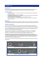
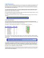
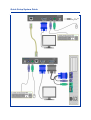
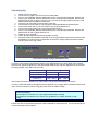
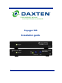
Voyager 300
Installation guide
Specifications
Package Contents:
1 x Voyager 300 Local Unit
1 x Voyager 300 Remote Unit
1 x PC KVM Cable 1.8 m
1 x Regulated Power Adaptor
Optional Items:
1024-00SE
Skew Compensator
1034-00A
19” Rack Mount Kit for Local or Remote Unit
2141-01U
PS/2 to USB Adaptor
9014-00A
Local Unit Regulated Power Adaptor
Specifications:
Video Bandwidth (-3dB)
Maximum Resolution
Video I/O
Video Compatibility
Video Compensation
Video Coupling
Sync H/V
Console Switch Time
Input Power
Interconnect Cable
Local Unit:
150 MHz
Remote Unit: 230 MHz
1600 x 1200 @ 85 Hz
1.0V P-P
VGA, SVGA, XGA
4 Stages in 4 Ranges
DC
Separated TTL Level
< 1 second
Local Unit:
From PC, or via optional 5V DC 500mA Regulated PSU.
Remote Unit: 5V DC 500mA Regulated PSU. Running > 130mA
CAT 5, CAT 5E & CAT 6, Solid UTP/STP Cable, EIA/TIA 568 Wiring,
RJ45 Connectors.
Physical Properties:
Height
Local Unit
2.4 cm
Remote Unit
2.4 cm
Width
15.3 cm
15.3 cm
Depth
6.4 cm
6.4 cm
Weight
0.35 kg
0.35 kg
Operation and Storage parameters:
Operating Temperature:
0~40° C (32 to 104° F)
Humidity:
0~80% RH non-condensing
Storage Temperature:
-20~60° C (-4 to 140° F)
Compatibility:
Keyboard
PS/2
Mouse
Standard 2 button PS/2 mouse, Microsoft Intellimouse, Logitech PS/2 3 button mouse.
Computer
PS/2 and 100% compatible PC equipped with PS/2 ports
© Copyright 2004. All rights reserved.
Daxten, the Daxten logo, Voyager and The Brains Behind KVM Switching and Sharing are trademarks of Daxten Industries.
All other trademarks acknowledged.
Revision 1.1
Voyager 300
Introduction
Thank you for purchasing the Voyager 300 UTP Extender. This product will allow you to place your
Monitor and PS/2 Keyboard and PS/2 Mouse up to 350 meters away from your computer.
Product Features
¾
¾
¾
¾
¾
Allows a user to control a PC from up to 350 meters (1200 feet) away, using a single CAT5,
5e or CAT 6 cable.
No additional software is required for operation.
Adjustable Video Equalisation - Compensates for loss of image quality due to cable length in
several steps with or without extra gain.
Fully buffered signals to ensure consistent remote operation of your PC
Dual Access allows for an additional keyboard, monitor and PS/2 mouse to be connected
through the local unit.
Operation
The Voyager is simple to install, with no software is required. Just connect the units up as described in
quick setup system guide and you're ready to work. Switch the computer off before wiring up the units.
Hardware Installation
Before connecting your computer to the Voyager Local unit, please ensure that it is powered off.
Connect your console devices to the Voyager remote unit. Note: the Voyager Remote requires power.
If your computer does not have a PS/2 mouse or keyboard port, you can use a PS/2 to USB converter
(2141-01U). This will allow you to connect the Voyager to your computer. The keyboard and mouse
that you connect to the Voyager unit must be PS/2.
With the constant changes in computers keyboards and mice on the market, it is impossible to
guarantee universal compatibility for the Voyager’s keyboard/mouse emulation. The Voyager
emulation is compatible with almost all standard PC (Intel/AMD based) BIOS systems.
The local unit is normally powered from the computer through the keyboard connector. Some
computers do not supply enough power through the keyboard connector; this necessitates the use of
a 5VDC mains adapter on the local unit. The Voyager 300 Local Unit is equipped with a DC jack for
the use of an optional power supply. This jack is normally not used, since most computers supply
enough power through the keyboard connector.
If you daisy chain the local with other equipment, please use a separate 5 volt supply (9014-00A) for
the local unit.
Rear Panel Layout Voyager 300 Remote Unit
Rear Panel Layout Voyager 300 Local Unit
Cable Requirements
Cables to connect the Voyager Local unit to your PC’s system unit are supplied in the package. Your
keyboard, monitor and mouse will plug straight in to the Voyager Local and Voyager Remote Units.
The Voyager 300 is a dual access unit, in that it allows for an access point next to your computer as
well as access point up to 350m away.
The UTP / STP interconnect cable to connect the Voyager Local Unit to the Voyager Remote Unit is
not supplied with the Voyager units. If you do not have suitable CAT 5, 5E or 6 UTP or STP cable
fitted at you site, please consult your dealer.
The Local and Remote Units are connected by industry standard structured cabling (Category 5, 5E or
6 UTP/STP, 4-pair) terminated with RJ45 connectors.
The cable used should be solid trunk cable. Stranded patch cable will give poor results over longer
distances.
The connector wiring must meet the EIA/TIA 568 standard.
CAT5 Wiring Scheme
The Local-Remote interconnection cable is terminated in RJ45 connectors and should be wired
according to the EIA/TIA 568 (Scheme B preferred) industry standard. The Voyager will function with
other wiring schemes, but the video quality may be impaired.
Orientation: Looking into the RJ45 socket pin 1 is on the left and Pin 8 on the right.
Pin
1
2
3
4
5
6
7
8
Wire Colour
White/Orange
Orange/White
White/Green
Blue/White
White/Blue
Green/White
White/Brown
Brown/White
Wire
T2
R2
T3
R1
T1
R3
T4
R4
Pair
2
2
3
1
1
3
4
4
The Voyager has been tested with all major makes of CAT 5 cable including BICC-VERO, Mohawk,
and Brand-Rex. The Voyager has also been tested with most major makes of CAT 5E and CAT6 with
good results.
Note: That failure to wire the twisted pairs correctly will impair the video quality
dramatically and / or prevent correct operation.
This Voyager 300 extender is designed for use up to a maximum cable length of 350m/1200ft. Up to
100m the max. resolution should be at 1600 x 1200 @ 85Hz. At a length of 300m the video quality
should still be acceptable even at a screen resolution of 1024 x 768 (85Hz). With cable distances of
300m and over you may require a skew compensator (1024-00SE) this will depend on the quality of
your CAT 5 or CAT 6 cable and or monitor resolution.
Although a single continuous length of interconnect cable is preferable, operation is possible through
multiple Patch Panels. However, the more patch panels the cable is routed through, the greater the
chance of video signal degradation.
Quick Setup System Guide
Connecting Up
1.
2.
3.
4.
5.
6.
7.
8.
9.
10.
11.
Switch off your computer.
Connect the Voyager Local Unit to the PC KVM Cable
Plug in your Keyboard, Monitor and Mouse into the corresponding Keyboard, Monitor and
Mouse ports on the Voyager Local Unit. (You can use the Voyager without having a Local
Keyboard, Monitor and Mouse connected).
Connect your UTP cable to the Voyager Local Unit.
Connect the PC KVM cable to your computer’s Keyboard Monitor and Mouse ports.
Connect the other end of your UTP cable to the Voyager Remote Unit.
Connect the power supply unit to the Voyager Remote unit.
Plug in your Keyboard, Monitor and Mouse into the corresponding Keyboard, Monitor and
Mouse ports on the Voyager Remote Unit.
Power on your computer.
Check that the keyboard and mouse operate correctly.
Adjust the Video Equalisation if required on the Voyager Remote Unit which contains video
equalisation circuitry that will compensate for the loss in image quality experienced when
sending video over long cables..
Front Panel Layout Voyager 300 Remote Unit
To set the correct level of equalisation there are two adjustments on the front panel of the Voyager
Remote Unit. Adjust the Distance to the appropriate cable length, and then adjust the Eq to fine tune
the setting (these only need to be set once.)
LED
No Light
Led 1 On ─
Led 2 On ═
Cable Length
0 – 100 m
0 – 350 ft
80 – 220 m 250 – 725 ft
190 – 350 m 600 – 1200 ft
The remote unit (when installed in its final location) may be left permanently powered up.
In order to make the distance settings as easy as possible, the Voyager 300 incorporates three boost
steps, which means there will be a big gain jump when the LED’s change.
Note: Always try the EQ adjustment before and after the LED’s change, to achieve the
best picture quality.
Always adjust the EQ after you have adjusted the Distance setting.
The distances indicated by the LED are only guidelines, as cables can differ in their
quality.
Please note that for all practical purposes cable equalisation cannot be exact - the remote image will
never be as sharp as the original.
Service Information
Technical Support
If you cannot determine the nature of a problem, please call Daxten and ask for Technical Support. If
possible, call from a phone located near the unit, as we may be able to solve your problem directly
over the phone. If we cannot solve your problem, and determine that the fault is in the unit, we will
issue a Return Material Authorisation (RMA) number that must appear on the outside of all returned
products. The unit should be double-packed in the original container, insured, and shipped to the
address given to you by our Technical Support representative. The Technical Support offices are
found on the back of this manual.
Limited Warranty
Daxten warrants to the end user that this product is and will be free from defects in materials and
workmanship for a period of 24 months from the date of purchase. If during the warranty period the
product should fail, the purchaser must promptly call Daxten for a RETURN MATERIALS
AUTHORIZATION (RMA) number. Make sure that the RMA number appears on the packing slip, proof
of purchase, AND ON THE OUTSIDE OF EACH SHIPPING CARTON. Unauthorized returns or collect
shipments will be refused.
Ship prepaid to the Daxten office (see back page) where you purchased your product. The above
limited warranty is voided by occurrence of any of the following events, upon which the product is
provided as is, with all faults, and with all disclaimers of warranty identified below:
1.
2.
3.
4.
5.
6.
7.
If non-Daxten approved power supply or cabling is attached to the product.
If defect or malfunction was caused by abuse, mishandling, unauthorized repair, or use other
than intended.
If unauthorized modifications were made to product.
If unreported damages occurred in any shipment of the product.
If damages were due to or caused by equipment or software not provided by Daxten.
If the product is used with non-grounded or incorrectly polarized AC power.
If the product is used in contradiction to any instruction provided by any User Guide or
Instruction Sheet provided to you or with the product.
EXCEPT AS SPECIFICALLY PROVIDED ABOVE AND TO THE MAXIMUM EXTENT ALLOWED BY
LAW, DAXTEN DISCLAIMS ALL WARRANTIES AND CONDITIONS WHETHER EXPRESS,
IMPLIED, OR STATUTORY AS TO ANY MATTER WHATSOEVER INCLUDING, WITHOUT
LIMITATION, TITLE, NON-INFRINGEMENT, CONDITION, MERCHANTABILITY OR FITNESS FOR
ANY PARTICULAR OR INTENDED PURPOSE.
EXCEPT AS EXPRESSLY PROVIDED ABOVE AND TO THE MAXIMUM EXTENT ALLOWED BY
LAW, DAXTEN SHALL NOT BE LIABLE FOR ANY SPECIAL, INDIRECT OR CONSEQUENTIAL
DAMAGES (INCLUDING WITHOUT LIMITATION, LOSS OF PROFIT, LOSS OF BUSINESS, LOSS
OF INFORMATION, FINANCIAL LOSS, PERSONAL INJURY, LOSS OF PRIVACY OR
NEGLIGENCE) WHICH MAY BE CAUSED BY OR RELATED TO, DIRECTLY OR INDIRECTLY, THE
USE OF A PRODUCT OR SERVICE, THE INABILITY TO USE A PRODUCT OR SERVICE,
INADEQUACY OF A PRODUCT OR SERVICE FOR ANY PURPOSE OR USE THEREOF OR BY
ANY DEFECT OR DEFICIENCY THEREIN EVEN IF DAXTEN OR AN AUTHORIZED DAXTEN
DEALER HAS BEEN ADVISED OF THE POSSIBILITY OF SUCH DAMAGES OR LOSSES.
Waste Electrical and Electronic Equipment (WEEE)
Within the European this symbol indicates that this product should not be disposed in
household waste. It should be deposited at an appropriate facility to enable recovery and
recycling. For information on how to recycle this product, please check with the reseller of the
product that replaces this product "Take Back" or the original seller of this product.
www.daxten.com
Ireland
Bay 21
Free Zone West
Shannon, Co. Clare
[email protected]
www.daxten.ie
Tel: +353 (0) 61 23 4000
Fax: +353 (0) 61 23 4099
USA
811 W. Evergreen Ave
Suite 302A
Chicago, IL 60622
[email protected]
www.daxten.us
Tel: +1 312 475 0795
Fax: +1 312 475 0797
United Kingdom
5 Manhattan Business Park
Westgate
London W5 1UP
[email protected]
www.daxten.co.uk
Tel: +44 (0) 20 8991 6200
Fax: +44 (0) 20 8991 6299
•
•
•
Österreich
Künstlergasse 11/4
A-1150 Wien
[email protected]
www.daxten.at
Tel: +43 (0)1 879 77 65
Fax: +43 (0)1 879 77 65 30
Deutschland
Salzufer 16, Geb. B
10587 Berlin
[email protected]
www.daxten.de
Tel: +49 (0) 30 8595 37-0
Fax: +49 (0) 30 8595 37-99
Schweiz
Seebahnstr. 231
8004 Zürich
[email protected]
www.daxten.ch
Tel: +41 (0) 43 243 32 11
Fax: +41 (0) 43 243 32 16
•
•
•
España
C/Florian Rey, 8
50002 Zaragoza
Sweden
[email protected]
www.daxten.se
[email protected]
www.daxten.com.es
Tel: +34 902 197 662
Fax: +34 976 201 633
Denmark
[email protected]
www.daxten.dk
France
B.P 04 - 77
Route de Cheptainville
91630 Marolles-en-Hurepoix
[email protected]
www.daxten.fr
Tel: +33 (0)1 64 56 09 33
Fax: +33 (0)1 69 14 88 34
•
•
•
•