1
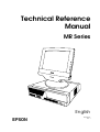
Technical Reference
Manual
MR Series
English
EPSON
403308709
Rev. I
MR Series Technical Reference Manual
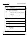
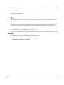
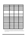
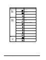
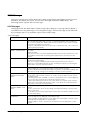
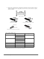
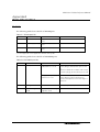
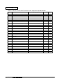
Revision Table
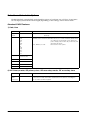
Rev.
Page
Description
Rev. A
All pages
Newly authorized
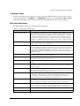
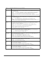
Rev. B
Chapter 5
BIOS updated from 2.06 to 2.08
9-2
Added explanation and listing of "touch panel position adjust jig" in "Required Tools".
Reason for change: The tool is now supplied for assembling the touch panel assembly.
9-18—20
Added new explanation for installation of the touch panel assembly.Reason for
change:
The touch panel assembly needs to be assembled and attached to the main frame
using the “touch panel position adjust jig“tool.
9-21
Added the explanation below in the “removing the LCD“.
Note:
When replacing the LCD, you need to change the electric-conductive tape also.
Reason for change: This explanation was missing.
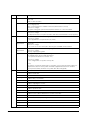
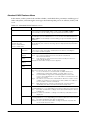
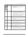
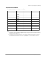
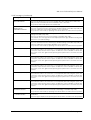
Rev. C
Rev. I
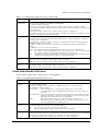
B-7,9,11,13
Added the parts in the Parts List and Exploded Diagram.
For DM-M820-014:
- upper plate (Ref# 120)
- lower plate (Ref# 121)
- touch panel assembly (Ref#:1056)
Reason for change;
The for the touch panel assembly unit was changed.
For IM-800:
- Ferrite core (Ref#; 220)
Reason for change: This explanation was missing.
1-7,9.2-2,4
Add the Indiividual Sales of IM and DM.
vii,viii,1-1,6,10,24,7-4
Add the AC Adapter OI-MR01.
1-3-6,11,2-1,61,2
Revision of the illustration.
3-1,3
Revision of the Hardware diagram.
4-1,3,17,19
Add the installation for Windows XP Professional Locally Procured Edition.
4-2
Add the explanation for Driver CD-ROM.
4-3
Add the Touch Panel Driver for Asian.
4-26-27,
Add the uninstaiiing the Serial Port Driver for Windows 2000.
4-32
Add the Installing the Service Pack 6a for Windows NT.
5-7
BIOS updated from 2.06 to 2.09.
5-16-19
Add the supplementary explanation for Power Management.
Chapter 8
Chanded the explanations for troubleshooting.
The changed points;
The each explanation for the trouble related to specific models is noted by an icon.
Reason for change;
The display with the touch panel assembly and without the MSR unit is newly supplied.
9-3
Addd the explanation for the DM-M820-015 in the work diagram for DM-M820.
Reason for change;
The display (DM-M820) with the touch panel assembly and without the MSR unit is
newly supplied.
i
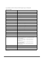
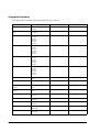
Rev.
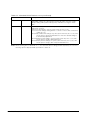
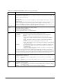
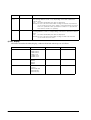
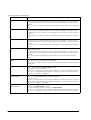
Rev.D
Page
Description
9-24,27,28,37
Added the explanation for disassembly and assemblyof the parts below.
-PCI card
-Switch cable assembly
9-29
The method of disassembly and assembly the CD/FDD bracket is changed.
The changed point.
One screw and stopper is added to fix the CD/FDD bracket correctly.
Reason for change;
The part is changed to prevent the CD/FDD bracket from connection failure.
B-11—15
Added parts list and block diagram for the model DM-M820-015.
Reason for change;
The display with the touch panel assembly and without the MSR unit is newly supplied.
9-19
Added the explanation of attaching the touch panel.
Reason for change;
To be supplied the touch panel unit (115) newly.
9-30
Appendix B
Changed the explanation of attaching the CD-ROM unit with the screws “C.B.screw.
2x2.5.F/ZN”.
Reason for change;
T wo screws “C.B.screw. 2x2.5.F/ZN“ attaching the CD-ROM unit are added.
9-32
Appendix B
Deleted the explanation of attaching the gasket to the FDD unit.
Reason for change;
We stop supplying the gasket.
Appendix B
Changed the partslist and Exploded Diagrams.
The added parts in the list is indicated below.
Touch panel unit (Reference number: 115)
Reason for change;
To be changed the composition of the parts.
Note;
The parts (Touch panel, Upper plate, Lower plate, Touch panel asssembly) will be not
supplied. Because the touch panel unit will be supplied instead of them. And the
touch panel assembly and the touch panel unit is interchangeality.
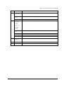
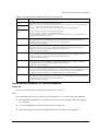
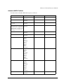
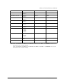
Rev.E
ii
1-1,7,9-37
Add the 2.5”HDD.
1-3
Add the Inside view.
1-7
Add the Lithium Battery.
1-8,9,AppB
Add the Gray color Models.
5-12,27
Add the On board Lan Boot ROM.
6-2
Add the Adjusting the volume.
8-8
Add the Unable to Read Data from HDD.
8-11
Add the Speaker Faults.
9-29
Add the RAID Card.
9-31,34
Add the Power cable is differentn for 3.5”HDD or 2.5”HDD.
9-45
Add the Speaker.
A-1
Add the 2.5”HDD Jumper Settings.
B-16
Revision of the Parts list IM-800 for 3.5”HDD Model.
B-19,20
Add the Parts list IM-800 for 2.5”HDD Model and Speaker Model.
B-21
Add the IM-800 for 2.5”HDD Model and Speaker Model Component Block.
Rev. I
MR Series Technical Reference Manual
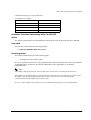
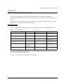
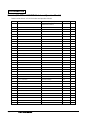
Rev.
Page
Description
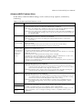
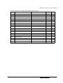
Rev.F
4-73-77
5-1,15,19,20
5-30
Add the HDD Power Down Settings.
5-1,2,15,19
5-20,30
Add the BIOS Ver.2.13.00.
3-6
Add the RTC (Real Time Clock).
v,vii
1-1,3,4,, 9,10
2-1,3,5,6
3-1,4,,6
8-3,14,15,18
8-23
9-25,30,31
9-51 -54
B-16 -24
Add the IM-800 with TM Printer Power Supply model.
1-1,11
B-2 -15
Add the DM-M820 High brightness model.
9-33,42
Add the notes.
9-50
Add the Speaker instdliation.
B-16 -24
Add the COM cable, B.
Rev. H
7-1,4 -6
9-2,4,27 -39
B-11 -15
Add the change of LCD.
Rev.I
9-68,70
Add the Cautions.
Rev.G
Rev. I
iii
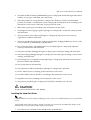
Cautions
❏ No part of this document may be reproduced, stored in a retrieval system, or transmitted in
any form or by any means, electronic, mechanical, photocopying, recording, or otherwise,
without the prior written permission of Seiko Epson Corporation.
❏ The contents of this document are subject to change without notice. Please contact us for the
latest information.
❏ While every precaution has been taken in the preparation of this document, Seiko Epson
Corporation assumes no responsibility for errors or omissions.
❏ Neither is any liability assumed for damages resulting from the use of the information
contained herein.
❏ Neither Seiko Epson Corporation nor its affiliates shall be liable to the purchaser of this
product or third parties for damages, losses, costs, or expenses incurred by the purchaser or
third parties as a result of: accident, misuse, or abuse of this product or unauthorized
modifications, repairs, or alterations to this product, or (excluding the U.S.) failure to strictly
comply with Seiko Epson Corporation’s operating and maintenance instructions.
❏ Seiko Epson Corporation shall not be liable against any damages or problems arising from
the use of any options or any consumable products other than those designated as Original
EPSON Products or EPSON Approved Products by Seiko Epson Corporation.
EPSON is registered trademark of Seiko Epson Corporation.
Intel and Celeron are registered trademarks of Intel Corporation.
IBM, PC/AT, and PS/2 are registered trademarks of International Business Machines
Corporation.
Microsoft, Windows, MS-DOS and Windows NT are registered trademarks of Microsoft
Corporation.
General Notice: Other product and company names used herein are for identification purposes
only and may be trademarks of their respective companies.
Copyright © 2002 by Seiko Epson Corporation, Japan.
iv
Rev. I
MR Series Technical Reference Manual
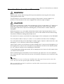
Important Safety Information
This section presents important information intended to ensure safe and effective use of this
product. Read this section carefully, and store it in an accessible location.
Key to Symbols
The symbols in this manual are identified by their level of importance, as defined below. Read
the following carefully before handling the product.
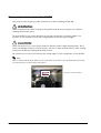
WARNING:
Warnings must be followed carefully to avoid serious bodily injury.
CAUTION:
Cautions must be observed to avoid minor injury to yourself or damage to your
equipment.
Safety Precautions for the IM-800
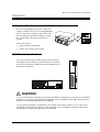
WARNING:
If you are using 100-127 V power, set the AC voltage select switch to 115.
If you are using 200-240 V power, set the AC voltage select switch to 230. (The factory
setting is 230.) If the setting is wrong, the system will be damaged and will not operate.
(For the standard model)
Unplug the power cable immediately if the IM-800 produces smoke, a strange odor, or
unusual noise. Continued use may lead to fire or electric shock. Contact your dealer or
an EPSON service center for advice.
Never insert or disconnect the power plug with wet hands. Doing so may result in severe
shock.
Do not allow foreign objects to fall into this product. Penetration by foreign objects may
lead to fire or shock.
If water or other liquid spills into this product, turn off the front power switch, unplug the
power cable immediately, and then contact your dealer or an EPSON service center for
advice. Continued usage may lead to fire or shock.
Always supply power directly from a standard domestic power outlet.
Do not place multiple loads on the power outlet (wall outlet). Overloading the outlet
may lead to fire.
The equipment must be installed near the electrical outlet, and the outlet must be easily
accessible.
Do not attempt to open or disassemble the internal lithium battery. This could result in
burns or release of hazardous chemicals.
Rev. I
v
Do not charge the internal lithium battery or leave it in a hot place such as near a fire or
on a heater because it could overheat and ignite.
When you dispose of the internal lithium battery, insulate it by wrapping the terminals
with tape. Mixing the battery with other metals or batteries may lead to fire, heat, or
explosion.
Be sure your power cable meets the relevant safety standards and includes a power
system ground terminal (PE terminal).
There is a ventilation opening on the right side; do not place any object in front of it. If
you set this product upright, be sure the ventilation opening is on the top. Do not place
any object on top of the ventilation opening.
Handle the power cable with care. Improper handling may lead to fire or shock.
Do not modify or attempt to repair the cable.
Do not place any object on top of the cable.
Avoid excessive bending, twisting, and pulling of the cable.
Do not place the cable near heating equipment.
Check that the plug is clean before plugging it in.
Be sure to push the prongs all the way in.
Do not use a damaged cable.
Regularly remove the power plug from the outlet and clean the base of the prongs and
between the prongs. If you leave the power plug in the outlet for a long time, dust may
collect on the base of the prongs, causing a short and fire.
CAUTION:
When replacing the battery, use only an equivalent type battery recommended by the
manufacturer. If your system has a module containing a lithium battery, replace it only
with the same module type made by the same manufacturer. The battery contains
lithium and can explode if not properly used, handled, or disposed of.
Do not connect cables other than those specified in this manual. Doing so may result in
fire or improper operation.
Do not connect the unit to electrical outlets that are close to devices that generate
voltage fluctuations or electrical noise. In particular, stay clear of devices that use large
electric motors.
Always connect the power cable to the IM-800 before plugging it into the wall outlet.
Be sure to push the plug of the power cable all the way into the AC inlet of this product.
The plug should make contact with the back of the inlet.
When disconnecting the power cable, hold the plug firmly. Do not tug on the cord itself.
vi
Rev. I
MR Series Technical Reference Manual
Be sure to set this product on a firm, stable, horizontal surface. The product may break or
cause injury if it falls.
Do not use the unit in locations subject to high humidity or dust levels. Excessive humidity
and dust may cause equipment damage, fire, or shock.
Do not use the unit in locations subject to liquids, since this product is not waterproof.
Do not use the product where inflammable fumes of gasoline, benzine, thinner or other
inflammable liquids may be in the air. Doing so may cause an explosion or fire.
Do not place heavy objects on top of this product. Equipment may fall or collapse,
causing breakage and possible injury.
To ensure safety, unplug this product before leaving it unused for an extended period.
Do not drop, bump, or otherwise subject this product to strong vibration or impact.
Do not block the openings on this product. Be sure not to install the product in a narrow
place that is not well ventilated, not to place it on any bedding or carpet and not to put
any cloth such as a tablecloth or blanket on it. The openings are provided for the
ventilation necessary to ensure reliable operation and protection from overheating or
fire.
Be sure to attach all covers after setup. If they are not attached, foreign matter may
enter this product and it may not operate correctly.
Never clean the product with thinner, benzine, alcohol, or other such solvent.
Do not use aerosol sprayers containing flammable gas inside or around this product.
Doing so may cause fire.
Do not use this product with any voltage other than the specified one. Doing so may
lead to fire.
When a power cable for the TM printer is connected, do not short-circuit its connector
pins. (For the 24V model)
Do not insert fingers or foreign matter into the CD-ROM disk tray or openings. Doing so
may lead to fire, shock, or injury.
Never hold this product by the rear cover, the front panel, or the CD-ROM disk tray. They
cannot support the weight of the product, so it may fall onto the floor.
Make sure that the total power requirements of all devices receiving power from this
product do not exceed the power limitation. See the specifications for more detailed
information.
Be careful not to cut your finger on any edge of the unit.
Be sure to use EPSON supplied DIMMs, HDDs, and CPUs.
Before using a PCI card, it is your responsibility to examine it carefully to confirm whether
its specifications conform to the specifications described in this manual. To get the latest
information about which PCI board can be used with this product, contact your EPSON
dealer.
Rev. I
vii
If you turn off the unit, wait at least 10 seconds before you turn it on again.
Safety Precautions for the DM-M820
WARNING:
Turn off the power switch immediately and unplug the DC plug if the DM-M820 or AC
Adapter produces smoke, a strange odor, or unusual noise. Continued use may lead to
fire or electric shock. Contact your dealer or an EPSON service center for advice.
The DM-M820 contains a glass panel. If the DM-M820 is dropped or treated roughly, the
glass may break.
Do not place your LCD Monitor in direct sunlight or near a heat source.
Do not allow foreign objects to fall into this product. Penetration by foreign objects may
lead to fire or shock.
If water or other liquid spills into this product, turn off the power switch, unplug the DC
plug immediately, and then contact your dealer or an EPSON service center for advice.
Continued usage may lead to fire or shock.
CAUTION:
Do not connect cables other than those specified in this manual. Doing so may result
improper operation.
Be sure to set this product on a firm, stable, horizontal surface. The product may break or
cause injury if it falls.
Do not use the unit in locations subject to high humidity or dust levels. Excessive humidity
and dust may cause equipment damage, fire, or shock.
Do not use the unit in locations subject to liquids, since this product is not waterproof.
Do not use the product where inflammable fumes of gasoline, benzine, thinner or other
inflammable liquids may be in the air. Doing so may cause an explosion or fire.
To ensure safety, unplug this product before leaving it unused for an extended period.
Do not drop, bump, or otherwise subject this product to strong vibration or impact.
Never clean the product with thinner, benzine or other such solvent.
Do not use aerosol sprayers containing flammable gas inside or around this product.
Doing so may cause fire.
If you want to use a compressed air product, such as an air duster, for cleaning during
repair and maintenance, use of products containing flammable gas is prohibited.
Be sure to use this product with all covers attached.
Be careful not to cut your finger on any edge of the unit.
viii
Rev. I
MR Series Technical Reference Manual
Safety Precautions for the OI-MR01 AC Adapter
WARNING:
Shut down your equipment immediately if it produces smoke, a strange odor, or unusual
noise. Continued use may lead to fire or electric shock. Immediately unplug the
equipment and contact your dealer or a SEIKO EPSON service center for advice.
Never attempt to repair this product yourself. Improper repair work can be dangerous.
Never disassemble or modify this product. Tampering with this product may result in
injury, fire, or electric shock.
Never insert or disconnect the power plug with wet hands. Doing so may result in severe
shock.
Do not allow foreign matter to fall into the equipment. Penetration of foreign objects
may lead to fire or shock.
If water or other liquid spills into this equipment, unplug the power cable immediately,
and then contact your dealer or a SEIKO EPSON service center for advice. Continued
usage may lead to fire or shock.
Do not place multiple loads on the power outlet (wall outlet). Overloading the outlet
may lead to fire.
Always supply power directly from a standard domestic power outlet.
Handle the power cable with care. Improper handling may lead to fire or shock.
Do not modify or attempt to repair the cable.
Do not place any object on top of the cable.
Avoid excessive bending, twisting, and pulling of the cable.
Do not place cord near heating equipment.
Check that the plug is clean before plugging it in.
Be sure to push the prongs all the way in.
If the cable becomes damaged, obtain a replacement from your dealer or a SEIKO
EPSON service center.
Regularly remove the power plug from the outlet and clean the base of the prongs and
between the prongs. If you leave the power plug in the outlet for a long time, dust may
collect on the base of the prongs, causing a short and fire.
Rev. I
ix
CAUTION:
Be sure your power cable meets the relevant safety standards and includes a powersystem ground terminal (PE terminal).
Be sure to use this product only with a DM-M820 LCD unit. Do not connect it to
equipment from other manufacturers. Use this product only for its intended application.
Improper usage may lead to equipment damage, fire, or shock.
Be sure to set this unit on a firm, stable, horizontal surface. Product may break or cause
injury if it falls.
Do not use in locations subject to high humidity or dust levels. Excessive humidity and
dust may cause equipment damage, fire, or shock.
Do not place heavy objects on top of this product. Never stand or lean on this product.
Equipment may fall or collapse, causing breakage and possible injury.
To ensure safety, please unplug this product prior to leaving it unused for an extended
period.
Be sure the product is not covered with any fabric, such as a blanket or tablecloth,
during use. This may cause overheating inside the product and lead to fire.
x
Rev. I
MR Series Technical Reference Manual
About this Manual
Aim of the Manual
This manual was created to provide all information necessary for system planning, design,
installation, application, and service of the MR series for designers and developers of POS
systems and for servicers of the products.
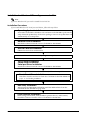
Manual Contents
The manual is made up of the following sections:
Chapter 1
Features and Overview
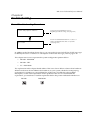
Chapter 2
Setup for the IM-800 and the DM-D820
Chapter 3
Hardware Specifications
Chapter 4
OS and Drivers
Chapter 5
BIOS Functions
Chapter 6
Operation of the IM-800 and the DM-D820
Chapter 7
Maintenance and Adjustment
Chapter 8
Troubleshooting
Chapter 9
Disassembly and Assembly
Appendix A
Jumper Settings
Appendix B
Parts Information
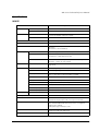
Related Documentation
Documents related to the MR Series are listed below.
Rev. I
Name of document
Description
IM-800 User’s Manual
Provides information to enable POS operators to use the
IM-800 safely and correctly.
DM-M820 User’s Manual
Provides information to enable POS operators to use the
DM-M820 safely and correctly.
OI-MR01 User’s Manual
Provides information to enable POS operators to use the
AC Adapter OI-MR01 safely.
xi
Contents
Revision Table . . . . . . . . . . . . . . . . . . . . . . . . . . . . . . . . . . . . . . . . . . . . . . . . . . . . . . . . . . . . . . . . . . . . . . . . . . . . . .
Important Safety Information . . . . . . . . . . . . . . . . . . . . . . . . . . . . . . . . . . . . . . . . . . . . . . . . . . . . . . . . . . . . . . . . . .
Key to Symbols . . . . . . . . . . . . . . . . . . . . . . . . . . . . . . . . . . . . . . . . . . . . . . . . . . . . . . . . . . . . . . . . . . . . . . . . . .
Safety Precautions for the IM-800 . . . . . . . . . . . . . . . . . . . . . . . . . . . . . . . . . . . . . . . . . . . . . . . . . . . . . . . . . .
Safety Precautions for the DM-M820 . . . . . . . . . . . . . . . . . . . . . . . . . . . . . . . . . . . . . . . . . . . . . . . . . . . . . . .
Safety Precautions for the OI-MR01 AC Adapter . . . . . . . . . . . . . . . . . . . . . . . . . . . . . . . . . . . . . . . . . . . . .
About this Manual . . . . . . . . . . . . . . . . . . . . . . . . . . . . . . . . . . . . . . . . . . . . . . . . . . . . . . . . . . . . . . . . . . . . . . . . . . .
Aim of the Manual . . . . . . . . . . . . . . . . . . . . . . . . . . . . . . . . . . . . . . . . . . . . . . . . . . . . . . . . . . . . . . . . . . . . . . .
Manual Contents . . . . . . . . . . . . . . . . . . . . . . . . . . . . . . . . . . . . . . . . . . . . . . . . . . . . . . . . . . . . . . . . . . . . . . . .
Related Documentation . . . . . . . . . . . . . . . . . . . . . . . . . . . . . . . . . . . . . . . . . . . . . . . . . . . . . . . . . . . . . . . . . . .
Contents . . . . . . . . . . . . . . . . . . . . . . . . . . . . . . . . . . . . . . . . . . . . . . . . . . . . . . . . . . . . . . . . . . . . . . . . . . . . . . . .
i
v
v
v
viii
ix
xi
xi
xi
xi
xii
Chapter 1 Features and Overview
Features . . . . . . . . . . . . . . . . . . . . . . . . . . . . . . . . . . . . . . . . . . . . . . . . . . . . . . . . . . . . . . . . . . . . . . . . . . . . . . . . . . . .
IM-800 Features . . . . . . . . . . . . . . . . . . . . . . . . . . . . . . . . . . . . . . . . . . . . . . . . . . . . . . . . . . . . . . . . . . . . . . . . .
DM-M820 Features . . . . . . . . . . . . . . . . . . . . . . . . . . . . . . . . . . . . . . . . . . . . . . . . . . . . . . . . . . . . . . . . . . . . . . .
Model Configurations . . . . . . . . . . . . . . . . . . . . . . . . . . . . . . . . . . . . . . . . . . . . . . . . . . . . . . . . . . . . . . . . . . . . . . . .
IM-800 . . . . . . . . . . . . . . . . . . . . . . . . . . . . . . . . . . . . . . . . . . . . . . . . . . . . . . . . . . . . . . . . . . . . . . . . . . . . . . . . .
DM-M820 . . . . . . . . . . . . . . . . . . . . . . . . . . . . . . . . . . . . . . . . . . . . . . . . . . . . . . . . . . . . . . . . . . . . . . . . . . . . . . .
Part Names for IM-800 . . . . . . . . . . . . . . . . . . . . . . . . . . . . . . . . . . . . . . . . . . . . . . . . . . . . . . . . . . . . . . . . . . . . . . .
Part Names for DM-M820 . . . . . . . . . . . . . . . . . . . . . . . . . . . . . . . . . . . . . . . . . . . . . . . . . . . . . . . . . . . . . . . . . . . . .
Specifications . . . . . . . . . . . . . . . . . . . . . . . . . . . . . . . . . . . . . . . . . . . . . . . . . . . . . . . . . . . . . . . . . . . . . . . . . . . . . . .
IM-800 . . . . . . . . . . . . . . . . . . . . . . . . . . . . . . . . . . . . . . . . . . . . . . . . . . . . . . . . . . . . . . . . . . . . . . . . . . . . . . . . .
DM-M820 . . . . . . . . . . . . . . . . . . . . . . . . . . . . . . . . . . . . . . . . . . . . . . . . . . . . . . . . . . . . . . . . . . . . . . . . . . . . . . .
AC Adapter (OI-MR01)* . . . . . . . . . . . . . . . . . . . . . . . . . . . . . . . . . . . . . . . . . . . . . . . . . . . . . . . . . . . . . . . . . .
Dimensions . . . . . . . . . . . . . . . . . . . . . . . . . . . . . . . . . . . . . . . . . . . . . . . . . . . . . . . . . . . . . . . . . . . . . . . . . . . . . . . . .
IM-800 . . . . . . . . . . . . . . . . . . . . . . . . . . . . . . . . . . . . . . . . . . . . . . . . . . . . . . . . . . . . . . . . . . . . . . . . . . . . . . . . .
DM-M820 . . . . . . . . . . . . . . . . . . . . . . . . . . . . . . . . . . . . . . . . . . . . . . . . . . . . . . . . . . . . . . . . . . . . . . . . . . . . . . .
1-1
1-1
1-1
1-2
1-2
1-2
1-3
1-6
1-9
1-9
1-11
1-12
1-13
1-13
1-13
Chapter 2 Setup for the IM-800 and the DM-M820
Setting the AC Voltage for the IM-800 (For the Standard model) . . . . . . . . . . . . . . . . . . . . . . . . . . . . . . . . . . . .
IM-800 Installation Positions . . . . . . . . . . . . . . . . . . . . . . . . . . . . . . . . . . . . . . . . . . . . . . . . . . . . . . . . . . . . . . . . . .
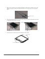
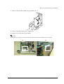
Installing the DM-M820 . . . . . . . . . . . . . . . . . . . . . . . . . . . . . . . . . . . . . . . . . . . . . . . . . . . . . . . . . . . . . . . . . . . . . . .
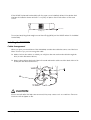
Cable Arrangement . . . . . . . . . . . . . . . . . . . . . . . . . . . . . . . . . . . . . . . . . . . . . . . . . . . . . . . . . . . . . . . . . . . . . .
Connecting the DM-M820 . . . . . . . . . . . . . . . . . . . . . . . . . . . . . . . . . . . . . . . . . . . . . . . . . . . . . . . . . . . . . . . . . . . . .
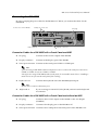
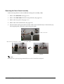
Connector Cables for a DM-M820 with a Touch Panel and MSR . . . . . . . . . . . . . . . . . . . . . . . . . . . . . . . .
Connector Cables for a DM-M820 with a Touch Panel and without an MSR . . . . . . . . . . . . . . . . . . . . . .
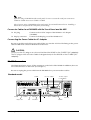
Connector Cables for a DM-M820 with No Touch Panel and No MSR . . . . . . . . . . . . . . . . . . . . . . . . . . .
Connecting the Power Cable for AC Adapter . . . . . . . . . . . . . . . . . . . . . . . . . . . . . . . . . . . . . . . . . . . . . . . .
IM-800 Connectors . . . . . . . . . . . . . . . . . . . . . . . . . . . . . . . . . . . . . . . . . . . . . . . . . . . . . . . . . . . . . . . . . . . . . . . . . . .
Connecting Other Peripheral Devices to the IM-800 . . . . . . . . . . . . . . . . . . . . . . . . . . . . . . . . . . . . . . . . . . . . . .
Serial Device Information . . . . . . . . . . . . . . . . . . . . . . . . . . . . . . . . . . . . . . . . . . . . . . . . . . . . . . . . . . . . . . . . .
Connecting a Serial Modem to the IM-800 . . . . . . . . . . . . . . . . . . . . . . . . . . . . . . . . . . . . . . . . . . . . . . . . . . .
USB Device Information . . . . . . . . . . . . . . . . . . . . . . . . . . . . . . . . . . . . . . . . . . . . . . . . . . . . . . . . . . . . . . . . . .
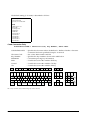
Keyboard and Mouse . . . . . . . . . . . . . . . . . . . . . . . . . . . . . . . . . . . . . . . . . . . . . . . . . . . . . . . . . . . . . . . . . . . . .
PCI Cards . . . . . . . . . . . . . . . . . . . . . . . . . . . . . . . . . . . . . . . . . . . . . . . . . . . . . . . . . . . . . . . . . . . . . . . . . . . . . . . . . . .
Connecting the Power Cable . . . . . . . . . . . . . . . . . . . . . . . . . . . . . . . . . . . . . . . . . . . . . . . . . . . . . . . . . . . . . . . . . .
Attaching the Rear Cover . . . . . . . . . . . . . . . . . . . . . . . . . . . . . . . . . . . . . . . . . . . . . . . . . . . . . . . . . . . . . . . . . . . . .
xii
2-1
2-1
2-2
2-2
2-3
2-3
2-3
2-4
2-4
2-4
2-5
2-5
2-5
2-5
2-6
2-6
2-6
2-7
Rev. I
MR Series Technical Reference Manual
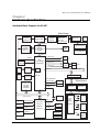
Chapter 3 Hardware Specifications
Hardware Block Diagram for IM-800 . . . . . . . . . . . . . . . . . . . . . . . . . . . . . . . . . . . . . . . . . . . . . . . . . . . . . . . .3-1
DMA . . . . . . . . . . . . . . . . . . . . . . . . . . . . . . . . . . . . . . . . . . . . . . . . . . . . . . . . . . . . . . . . . . . . . . . . . . . . . . . . . . . . . . .3-2
System Interrupts . . . . . . . . . . . . . . . . . . . . . . . . . . . . . . . . . . . . . . . . . . . . . . . . . . . . . . . . . . . . . . . . . . . . . . . . . . . .3-2
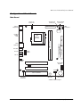
Configuration of Circuit Boards . . . . . . . . . . . . . . . . . . . . . . . . . . . . . . . . . . . . . . . . . . . . . . . . . . . . . . . . . . . . . . . .3-3
Main Board . . . . . . . . . . . . . . . . . . . . . . . . . . . . . . . . . . . . . . . . . . . . . . . . . . . . . . . . . . . . . . . . . . . . . . . . . . . . . .3-3
Riser Board . . . . . . . . . . . . . . . . . . . . . . . . . . . . . . . . . . . . . . . . . . . . . . . . . . . . . . . . . . . . . . . . . . . . . . . . . . . . . .3-4
COM Board . . . . . . . . . . . . . . . . . . . . . . . . . . . . . . . . . . . . . . . . . . . . . . . . . . . . . . . . . . . . . . . . . . . . . . . . . . . . . .3-4
DC24V Board . . . . . . . . . . . . . . . . . . . . . . . . . . . . . . . . . . . . . . . . . . . . . . . . . . . . . . . . . . . . . . . . . . . . . . . . . . . .3-4
PCI Slot . . . . . . . . . . . . . . . . . . . . . . . . . . . . . . . . . . . . . . . . . . . . . . . . . . . . . . . . . . . . . . . . . . . . . . . . . . . . . . . . . . . . .3-4
Power Supply . . . . . . . . . . . . . . . . . . . . . . . . . . . . . . . . . . . . . . . . . . . . . . . . . . . . . . . . . . . . . . . . . . . . . . . . . . . . . . . .3-5
Standard model . . . . . . . . . . . . . . . . . . . . . . . . . . . . . . . . . . . . . . . . . . . . . . . . . . . . . . . . . . . . . . . . . . . . . . . . . .3-5
24V model . . . . . . . . . . . . . . . . . . . . . . . . . . . . . . . . . . . . . . . . . . . . . . . . . . . . . . . . . . . . . . . . . . . . . . . . . . . . . . .3-6
Power Supply Capacities to Each Port . . . . . . . . . . . . . . . . . . . . . . . . . . . . . . . . . . . . . . . . . . . . . . . . . . . . . . .3-6
Lithium Battery . . . . . . . . . . . . . . . . . . . . . . . . . . . . . . . . . . . . . . . . . . . . . . . . . . . . . . . . . . . . . . . . . . . . . . . . . . . . . .3-7
MAC Address . . . . . . . . . . . . . . . . . . . . . . . . . . . . . . . . . . . . . . . . . . . . . . . . . . . . . . . . . . . . . . . . . . . . . . . . . . . . . . . .3-7
Chapter 4 OS and Drivers
Outline of This Chapter . . . . . . . . . . . . . . . . . . . . . . . . . . . . . . . . . . . . . . . . . . . . . . . . . . . . . . . . . . . . . . . . . . . . . . .4-1
Operating Systems . . . . . . . . . . . . . . . . . . . . . . . . . . . . . . . . . . . . . . . . . . . . . . . . . . . . . . . . . . . . . . . . . . . . . . . .4-1
Drivers and Utilities . . . . . . . . . . . . . . . . . . . . . . . . . . . . . . . . . . . . . . . . . . . . . . . . . . . . . . . . . . . . . . . . . . . . . .4-1
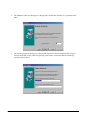
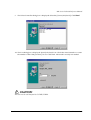
Windows 2000 Pre-Installed Model . . . . . . . . . . . . . . . . . . . . . . . . . . . . . . . . . . . . . . . . . . . . . . . . . . . . . . . . . . . . .4-4
Installation Procedure . . . . . . . . . . . . . . . . . . . . . . . . . . . . . . . . . . . . . . . . . . . . . . . . . . . . . . . . . . . . . . . . . . . . .4-4
Directory Configuration . . . . . . . . . . . . . . . . . . . . . . . . . . . . . . . . . . . . . . . . . . . . . . . . . . . . . . . . . . . . . . . . . . .4-6
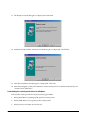
Windows 2000 Setup Procedure . . . . . . . . . . . . . . . . . . . . . . . . . . . . . . . . . . . . . . . . . . . . . . . . . . . . . . . . . . . .4-6
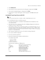
Installing the MSR Utility for Windows . . . . . . . . . . . . . . . . . . . . . . . . . . . . . . . . . . . . . . . . . . . . . . . . . . . . . .4-8
Recovering the OS . . . . . . . . . . . . . . . . . . . . . . . . . . . . . . . . . . . . . . . . . . . . . . . . . . . . . . . . . . . . . . . . . . . . . . . .4-9
Windows 98 Pre-Installed Model . . . . . . . . . . . . . . . . . . . . . . . . . . . . . . . . . . . . . . . . . . . . . . . . . . . . . . . . . . . . . . .4-11
Installation Procedure . . . . . . . . . . . . . . . . . . . . . . . . . . . . . . . . . . . . . . . . . . . . . . . . . . . . . . . . . . . . . . . . . . . . .4-11
Directory Configuration . . . . . . . . . . . . . . . . . . . . . . . . . . . . . . . . . . . . . . . . . . . . . . . . . . . . . . . . . . . . . . . . . . .4-12
Windows 98 Set-Up Procedure . . . . . . . . . . . . . . . . . . . . . . . . . . . . . . . . . . . . . . . . . . . . . . . . . . . . . . . . . . . . .4-13
Installing the MSR Utility for Windows . . . . . . . . . . . . . . . . . . . . . . . . . . . . . . . . . . . . . . . . . . . . . . . . . . . . . .4-13
Recovering the OS . . . . . . . . . . . . . . . . . . . . . . . . . . . . . . . . . . . . . . . . . . . . . . . . . . . . . . . . . . . . . . . . . . . . . . . .4-14
Installation for Windows XP Professional Locally Procured Edition . . . . . . . . . . . . . . . . . . . . . . . . . . . . . . . . .4-16
Installation Procedure . . . . . . . . . . . . . . . . . . . . . . . . . . . . . . . . . . . . . . . . . . . . . . . . . . . . . . . . . . . . . . . . . . . . .4-16
Installing the Serial Port Driver . . . . . . . . . . . . . . . . . . . . . . . . . . . . . . . . . . . . . . . . . . . . . . . . . . . . . . . . . . . . .4-17
Installing the Touch Panel Driver, MSR Utility and the Other Devices . . . . . . . . . . . . . . . . . . . . . . . . . . .4-18
Installation for Windows 2000 Professional Locally Procured Edition . . . . . . . . . . . . . . . . . . . . . . . . . . . . . . . .4-19
Installation Procedure . . . . . . . . . . . . . . . . . . . . . . . . . . . . . . . . . . . . . . . . . . . . . . . . . . . . . . . . . . . . . . . . . . . . .4-19
Installing the Intel Chipset Diver . . . . . . . . . . . . . . . . . . . . . . . . . . . . . . . . . . . . . . . . . . . . . . . . . . . . . . . . . . .4-22
Installing the Network Driver . . . . . . . . . . . . . . . . . . . . . . . . . . . . . . . . . . . . . . . . . . . . . . . . . . . . . . . . . . . . . .4-22
Installing the Display Driver . . . . . . . . . . . . . . . . . . . . . . . . . . . . . . . . . . . . . . . . . . . . . . . . . . . . . . . . . . . . . . .4-24
Installing the Sound Driver . . . . . . . . . . . . . . . . . . . . . . . . . . . . . . . . . . . . . . . . . . . . . . . . . . . . . . . . . . . . . . . .4-24
Installing the Serial Port Driver . . . . . . . . . . . . . . . . . . . . . . . . . . . . . . . . . . . . . . . . . . . . . . . . . . . . . . . . . . . . .4-25
Installing the Touch Panel Driver, MSR Utility and the Other Devices . . . . . . . . . . . . . . . . . . . . . . . . . . .4-25
Installation for Windows NT Locally procured edition . . . . . . . . . . . . . . . . . . . . . . . . . . . . . . . . . . . . . . . . . . . .4-26
Installation Procedure . . . . . . . . . . . . . . . . . . . . . . . . . . . . . . . . . . . . . . . . . . . . . . . . . . . . . . . . . . . . . . . . . . . . .4-26
Installing the Network Driver . . . . . . . . . . . . . . . . . . . . . . . . . . . . . . . . . . . . . . . . . . . . . . . . . . . . . . . . . . . . . .4-27
Installing Service Pack 6a . . . . . . . . . . . . . . . . . . . . . . . . . . . . . . . . . . . . . . . . . . . . . . . . . . . . . . . . . . . . . . . . . .4-31
Ultra DMA Setting for the HDD . . . . . . . . . . . . . . . . . . . . . . . . . . . . . . . . . . . . . . . . . . . . . . . . . . . . . . . . . . . .4-31
Installing the Display Driver . . . . . . . . . . . . . . . . . . . . . . . . . . . . . . . . . . . . . . . . . . . . . . . . . . . . . . . . . . . . . . .4-32
Installing the Sound Driver . . . . . . . . . . . . . . . . . . . . . . . . . . . . . . . . . . . . . . . . . . . . . . . . . . . . . . . . . . . . . . . .4-32
Installing the Serial Port Driver . . . . . . . . . . . . . . . . . . . . . . . . . . . . . . . . . . . . . . . . . . . . . . . . . . . . . . . . . . . . .4-33
Installing the Touch Panel Driver, MSR Utility and the Other Devices . . . . . . . . . . . . . . . . . . . . . . . . . . .4-33
Rev. I
xiii
Installation for Windows 98 Locally Procured Edition . . . . . . . . . . . . . . . . . . . . . . . . . . . . . . . . . . . . . . . . . . . .
Installation Procedure . . . . . . . . . . . . . . . . . . . . . . . . . . . . . . . . . . . . . . . . . . . . . . . . . . . . . . . . . . . . . . . . . . . .
Setup Procedure . . . . . . . . . . . . . . . . . . . . . . . . . . . . . . . . . . . . . . . . . . . . . . . . . . . . . . . . . . . . . . . . . . . . . . . . .
Installing the Chipset Driver for Intel . . . . . . . . . . . . . . . . . . . . . . . . . . . . . . . . . . . . . . . . . . . . . . . . . . . . . . .
Ultra DMA Setting for the HDD . . . . . . . . . . . . . . . . . . . . . . . . . . . . . . . . . . . . . . . . . . . . . . . . . . . . . . . . . . .
Installing the Network Driver . . . . . . . . . . . . . . . . . . . . . . . . . . . . . . . . . . . . . . . . . . . . . . . . . . . . . . . . . . . . .
Installing the Display Driver . . . . . . . . . . . . . . . . . . . . . . . . . . . . . . . . . . . . . . . . . . . . . . . . . . . . . . . . . . . . . .
Installing the Sound Driver . . . . . . . . . . . . . . . . . . . . . . . . . . . . . . . . . . . . . . . . . . . . . . . . . . . . . . . . . . . . . . .
Installing the Serial Port Driver . . . . . . . . . . . . . . . . . . . . . . . . . . . . . . . . . . . . . . . . . . . . . . . . . . . . . . . . . . . .
Installing the Touch Panel Driver, MSR Utility and the Other Devices . . . . . . . . . . . . . . . . . . . . . . . . . . .
Installation for MS-DOS Locally Procured Version . . . . . . . . . . . . . . . . . . . . . . . . . . . . . . . . . . . . . . . . . . . . . . .
Installation Procedure . . . . . . . . . . . . . . . . . . . . . . . . . . . . . . . . . . . . . . . . . . . . . . . . . . . . . . . . . . . . . . . . . . . .
Installing the CD-ROM Driver . . . . . . . . . . . . . . . . . . . . . . . . . . . . . . . . . . . . . . . . . . . . . . . . . . . . . . . . . . . . .
Installing the Network Driver . . . . . . . . . . . . . . . . . . . . . . . . . . . . . . . . . . . . . . . . . . . . . . . . . . . . . . . . . . . . .
Installing the Serial Port Driver . . . . . . . . . . . . . . . . . . . . . . . . . . . . . . . . . . . . . . . . . . . . . . . . . . . . . . . . . . . .
Installing the Touch Panel Driver, MSR utility and the Other Devices . . . . . . . . . . . . . . . . . . . . . . . . . . .
Installation of Other Drivers . . . . . . . . . . . . . . . . . . . . . . . . . . . . . . . . . . . . . . . . . . . . . . . . . . . . . . . . . . . . . . . . . . .
Installing the Touch Panel Driver for Windows . . . . . . . . . . . . . . . . . . . . . . . . . . . . . . . . . . . . . . . . . . . . . .
Installing the Touch Panel Driver for MS-DOS . . . . . . . . . . . . . . . . . . . . . . . . . . . . . . . . . . . . . . . . . . . . . . .
Installing the MSR Utility for Windows . . . . . . . . . . . . . . . . . . . . . . . . . . . . . . . . . . . . . . . . . . . . . . . . . . . . .
Installing the MSR Utility for MS-DOS . . . . . . . . . . . . . . . . . . . . . . . . . . . . . . . . . . . . . . . . . . . . . . . . . . . . . .
Setting of Windows and Drivers . . . . . . . . . . . . . . . . . . . . . . . . . . . . . . . . . . . . . . . . . . . . . . . . . . . . . . . . . . . . . . .
Touch Panel Driver for Windows . . . . . . . . . . . . . . . . . . . . . . . . . . . . . . . . . . . . . . . . . . . . . . . . . . . . . . . . . .
Touch Panel Driver for MS-DOS . . . . . . . . . . . . . . . . . . . . . . . . . . . . . . . . . . . . . . . . . . . . . . . . . . . . . . . . . . .
HDD Power Down Timer Setting . . . . . . . . . . . . . . . . . . . . . . . . . . . . . . . . . . . . . . . . . . . . . . . . . . . . . . . . . .
MSR Utility for Windows . . . . . . . . . . . . . . . . . . . . . . . . . . . . . . . . . . . . . . . . . . . . . . . . . . . . . . . . . . . . . . . . .
Automatic Definition Data Setting Utility for Windows . . . . . . . . . . . . . . . . . . . . . . . . . . . . . . . . . . . . . . .
MSR Utility for MS-DOS . . . . . . . . . . . . . . . . . . . . . . . . . . . . . . . . . . . . . . . . . . . . . . . . . . . . . . . . . . . . . . . . . .
Automatic Definition Data Setting Utility For MS-DOS . . . . . . . . . . . . . . . . . . . . . . . . . . . . . . . . . . . . . . .
4-34
4-34
4-35
4-35
4-36
4-37
4-39
4-39
4-40
4-40
4-41
4-41
4-42
4-42
4-44
4-44
4-45
4-45
4-49
4-50
4-51
4-51
4-51
4-72
4-73
4-77
4-79
4-82
4-87
Chapter 5 BIOS Functions
HDD Power Down Timer Setting . . . . . . . . . . . . . . . . . . . . . . . . . . . . . . . . . . . . . . . . . . . . . . . . . . . . . . . . . . . . . .
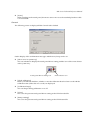
BIOS Setup . . . . . . . . . . . . . . . . . . . . . . . . . . . . . . . . . . . . . . . . . . . . . . . . . . . . . . . . . . . . . . . . . . . . . . . . . . . . . . . . . .
Operating Procedure . . . . . . . . . . . . . . . . . . . . . . . . . . . . . . . . . . . . . . . . . . . . . . . . . . . . . . . . . . . . . . . . . . . . .
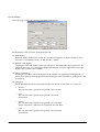
The help display . . . . . . . . . . . . . . . . . . . . . . . . . . . . . . . . . . . . . . . . . . . . . . . . . . . . . . . . . . . . . . . . . . . . . . . . .
Troubleshooting . . . . . . . . . . . . . . . . . . . . . . . . . . . . . . . . . . . . . . . . . . . . . . . . . . . . . . . . . . . . . . . . . . . . . . . . .
Changing settings . . . . . . . . . . . . . . . . . . . . . . . . . . . . . . . . . . . . . . . . . . . . . . . . . . . . . . . . . . . . . . . . . . . . . . . .
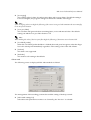
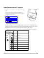
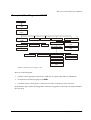
BIOS Setup Main Menu . . . . . . . . . . . . . . . . . . . . . . . . . . . . . . . . . . . . . . . . . . . . . . . . . . . . . . . . . . . . . . . . . . .
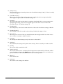
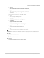
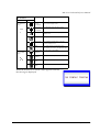
Standard CMOS Features Menu . . . . . . . . . . . . . . . . . . . . . . . . . . . . . . . . . . . . . . . . . . . . . . . . . . . . . . . . . . .
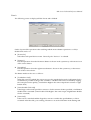
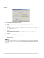
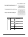
Advanced BIOS Features Menu . . . . . . . . . . . . . . . . . . . . . . . . . . . . . . . . . . . . . . . . . . . . . . . . . . . . . . . . . . . .
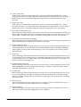
Advanced Chipset Features Menu . . . . . . . . . . . . . . . . . . . . . . . . . . . . . . . . . . . . . . . . . . . . . . . . . . . . . . . . .
Integrated Peripherals Menu . . . . . . . . . . . . . . . . . . . . . . . . . . . . . . . . . . . . . . . . . . . . . . . . . . . . . . . . . . . . . .
POWER MANAGEMENT SETUP Menu . . . . . . . . . . . . . . . . . . . . . . . . . . . . . . . . . . . . . . . . . . . . . . . . . . . .
Supplementary Explanation for Power Management . . . . . . . . . . . . . . . . . . . . . . . . . . . . . . . . . . . . . . . . .
PNP/PCI Configurations Menu . . . . . . . . . . . . . . . . . . . . . . . . . . . . . . . . . . . . . . . . . . . . . . . . . . . . . . . . . . .
Defaults and Selectable Options . . . . . . . . . . . . . . . . . . . . . . . . . . . . . . . . . . . . . . . . . . . . . . . . . . . . . . . . . . . . . . .
Standard CMOS Features . . . . . . . . . . . . . . . . . . . . . . . . . . . . . . . . . . . . . . . . . . . . . . . . . . . . . . . . . . . . . . . . .
Advanced BIOS Features . . . . . . . . . . . . . . . . . . . . . . . . . . . . . . . . . . . . . . . . . . . . . . . . . . . . . . . . . . . . . . . . .
Advanced Chipset Features . . . . . . . . . . . . . . . . . . . . . . . . . . . . . . . . . . . . . . . . . . . . . . . . . . . . . . . . . . . . . . .
Integrated Peripherals . . . . . . . . . . . . . . . . . . . . . . . . . . . . . . . . . . . . . . . . . . . . . . . . . . . . . . . . . . . . . . . . . . . .
POWER MANAGEMENT SETUP . . . . . . . . . . . . . . . . . . . . . . . . . . . . . . . . . . . . . . . . . . . . . . . . . . . . . . . . . .
PNP/PCI Configuration . . . . . . . . . . . . . . . . . . . . . . . . . . . . . . . . . . . . . . . . . . . . . . . . . . . . . . . . . . . . . . . . . .
Setting a Password . . . . . . . . . . . . . . . . . . . . . . . . . . . . . . . . . . . . . . . . . . . . . . . . . . . . . . . . . . . . . . . . . . . . . . .
Device Diagnostics Utility . . . . . . . . . . . . . . . . . . . . . . . . . . . . . . . . . . . . . . . . . . . . . . . . . . . . . . . . . . . . . . . . . . . . .
xiv
5-1
5-1
5-2
5-2
5-2
5-3
5-3
5-4
5-7
5-10
5-11
5-13
5-15
5-19
5-20
5-20
5-23
5-25
5-26
5-28
5-29
5-30
5-30
Rev. I
MR Series Technical Reference Manual
Chapter 6 Operation of the IM-800 and the DM-M820
IM-800 Power . . . . . . . . . . . . . . . . . . . . . . . . . . . . . . . . . . . . . . . . . . . . . . . . . . . . . . . . . . . . . . . . . . . . . . . . . . . . . . . .6-1
Force Power Off . . . . . . . . . . . . . . . . . . . . . . . . . . . . . . . . . . . . . . . . . . . . . . . . . . . . . . . . . . . . . . . . . . . . . . . . . .6-1
LEDs for IM-800 . . . . . . . . . . . . . . . . . . . . . . . . . . . . . . . . . . . . . . . . . . . . . . . . . . . . . . . . . . . . . . . . . . . . . . . . . . . . . .6-1
LEDs on Back . . . . . . . . . . . . . . . . . . . . . . . . . . . . . . . . . . . . . . . . . . . . . . . . . . . . . . . . . . . . . . . . . . . . . . . . . . . .6-1
Opening and Closing of the CD/FDD Cover . . . . . . . . . . . . . . . . . . . . . . . . . . . . . . . . . . . . . . . . . . . . . . . . . . . . .6-2
CD-ROM Emergency Ejection . . . . . . . . . . . . . . . . . . . . . . . . . . . . . . . . . . . . . . . . . . . . . . . . . . . . . . . . . . . . . .6-2
Adjusting the volume . . . . . . . . . . . . . . . . . . . . . . . . . . . . . . . . . . . . . . . . . . . . . . . . . . . . . . . . . . . . . . . . . . . . . . . . .6-2
DM-M820 Power . . . . . . . . . . . . . . . . . . . . . . . . . . . . . . . . . . . . . . . . . . . . . . . . . . . . . . . . . . . . . . . . . . . . . . . . . . . . .6-2
Indicators for DM-M820 . . . . . . . . . . . . . . . . . . . . . . . . . . . . . . . . . . . . . . . . . . . . . . . . . . . . . . . . . . . . . . . . . . . . . . .6-3
LEDs . . . . . . . . . . . . . . . . . . . . . . . . . . . . . . . . . . . . . . . . . . . . . . . . . . . . . . . . . . . . . . . . . . . . . . . . . . . . . . . . . . .6-3
Beep (only for models with an MSR) . . . . . . . . . . . . . . . . . . . . . . . . . . . . . . . . . . . . . . . . . . . . . . . . . . . . . . . .6-3
DM-M820 Operation . . . . . . . . . . . . . . . . . . . . . . . . . . . . . . . . . . . . . . . . . . . . . . . . . . . . . . . . . . . . . . . . . . . . . . . . . .6-3
Adjusting the View Angle . . . . . . . . . . . . . . . . . . . . . . . . . . . . . . . . . . . . . . . . . . . . . . . . . . . . . . . . . . . . . . . . .6-3
How to Use a Touch Panel (for the Touch Panel Model) . . . . . . . . . . . . . . . . . . . . . . . . . . . . . . . . . . . . . . .6-4
How to Read a Magnetic Stripe Card (for the Model with an MSR) . . . . . . . . . . . . . . . . . . . . . . . . . . . . . .6-4
Chapter 7 Maintenance and Adjustment
Cleaning the IM-800 Front Panel Ventilation Opening . . . . . . . . . . . . . . . . . . . . . . . . . . . . . . . . . . . . . . . . . . . . .7-1
Display Adjustment for DM-M820 . . . . . . . . . . . . . . . . . . . . . . . . . . . . . . . . . . . . . . . . . . . . . . . . . . . . . . . . . . . . . .7-1
Determining which procedure to use . . . . . . . . . . . . . . . . . . . . . . . . . . . . . . . . . . . . . . . . . . . . . . . . . . . . . . . .7-1
Display Adjustment (SERIAL NO. *xxxx00xxxx*) . . . . . . . . . . . . . . . . . . . . . . . . . . . . . . . . . . . . . . . . . . . . .7-2
Display Adjustment (SERIAL NO. *xxxx01xxxx*) . . . . . . . . . . . . . . . . . . . . . . . . . . . . . . . . . . . . . . . . . . . . .7-4
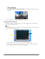
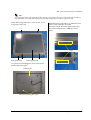
Touch Panel Calibration . . . . . . . . . . . . . . . . . . . . . . . . . . . . . . . . . . . . . . . . . . . . . . . . . . . . . . . . . . . . . . . . . . . . . . .7-7
Windows . . . . . . . . . . . . . . . . . . . . . . . . . . . . . . . . . . . . . . . . . . . . . . . . . . . . . . . . . . . . . . . . . . . . . . . . . . . . . . . .7-7
MS-DOS . . . . . . . . . . . . . . . . . . . . . . . . . . . . . . . . . . . . . . . . . . . . . . . . . . . . . . . . . . . . . . . . . . . . . . . . . . . . . . . . .7-7
Maintenance for AC Adapter . . . . . . . . . . . . . . . . . . . . . . . . . . . . . . . . . . . . . . . . . . . . . . . . . . . . . . . . . . . . . . . . . .7-8
Chapter 8 Troubleshooting
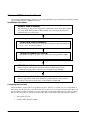
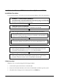
Flow of Troubleshooting Procedures . . . . . . . . . . . . . . . . . . . . . . . . . . . . . . . . . . . . . . . . . . . . . . . . . . . . . . . . . . . .8-1
Preparations for Troubleshooting . . . . . . . . . . . . . . . . . . . . . . . . . . . . . . . . . . . . . . . . . . . . . . . . . . . . . . . . . . . . . . .8-2
Problems and Possible Causes . . . . . . . . . . . . . . . . . . . . . . . . . . . . . . . . . . . . . . . . . . . . . . . . . . . . . . . . . . . . . . . . . .8-2
System Unable to Start . . . . . . . . . . . . . . . . . . . . . . . . . . . . . . . . . . . . . . . . . . . . . . . . . . . . . . . . . . . . . . . . . . . .8-3
Power Management Faults . . . . . . . . . . . . . . . . . . . . . . . . . . . . . . . . . . . . . . . . . . . . . . . . . . . . . . . . . . . . . . . . .8-6
System Clock Faults . . . . . . . . . . . . . . . . . . . . . . . . . . . . . . . . . . . . . . . . . . . . . . . . . . . . . . . . . . . . . . . . . . . . . .8-6
Memory Faults . . . . . . . . . . . . . . . . . . . . . . . . . . . . . . . . . . . . . . . . . . . . . . . . . . . . . . . . . . . . . . . . . . . . . . . . . . .8-7
Floppy Disk Drive Unit Faults . . . . . . . . . . . . . . . . . . . . . . . . . . . . . . . . . . . . . . . . . . . . . . . . . . . . . . . . . . . . . .8-8
HDD Faults . . . . . . . . . . . . . . . . . . . . . . . . . . . . . . . . . . . . . . . . . . . . . . . . . . . . . . . . . . . . . . . . . . . . . . . . . . . . . .8-8
CD-ROM Faults . . . . . . . . . . . . . . . . . . . . . . . . . . . . . . . . . . . . . . . . . . . . . . . . . . . . . . . . . . . . . . . . . . . . . . . . . .8-9
Network Faults . . . . . . . . . . . . . . . . . . . . . . . . . . . . . . . . . . . . . . . . . . . . . . . . . . . . . . . . . . . . . . . . . . . . . . . . . .8-10
Speaker Faults . . . . . . . . . . . . . . . . . . . . . . . . . . . . . . . . . . . . . . . . . . . . . . . . . . . . . . . . . . . . . . . . . . . . . . . . . . .8-11
LCD Display Faults . . . . . . . . . . . . . . . . . . . . . . . . . . . . . . . . . . . . . . . . . . . . . . . . . . . . . . . . . . . . . . . . . . . . . . .8-11
Touch Panel Faults . . . . . . . . . . . . . . . . . . . . . . . . . . . . . . . . . . . . . . . . . . . . . . . . . . . . . . . . . . . . . . . . . . . . . . .8-12
Printer Unit Faults . . . . . . . . . . . . . . . . . . . . . . . . . . . . . . . . . . . . . . . . . . . . . . . . . . . . . . . . . . . . . . . . . . . . . . . .8-14
Serial Port, Parallel Port, USB Port, and Keyboard/Mouse Port Faults . . . . . . . . . . . . . . . . . . . . . . . . . . .8-15
Faults that are Difficult to Diagnose . . . . . . . . . . . . . . . . . . . . . . . . . . . . . . . . . . . . . . . . . . . . . . . . . . . . . . . . .8-16
Power Supply Faults . . . . . . . . . . . . . . . . . . . . . . . . . . . . . . . . . . . . . . . . . . . . . . . . . . . . . . . . . . . . . . . . . . . . . .8-17
MSR Faults . . . . . . . . . . . . . . . . . . . . . . . . . . . . . . . . . . . . . . . . . . . . . . . . . . . . . . . . . . . . . . . . . . . . . . . . . . . . . .8-19
POST Messages . . . . . . . . . . . . . . . . . . . . . . . . . . . . . . . . . . . . . . . . . . . . . . . . . . . . . . . . . . . . . . . . . . . . . . . . . . . . . .8-20
Procedures for Testing the Power Supply . . . . . . . . . . . . . . . . . . . . . . . . . . . . . . . . . . . . . . . . . . . . . . . . . . . . . . . .8-23
Setup . . . . . . . . . . . . . . . . . . . . . . . . . . . . . . . . . . . . . . . . . . . . . . . . . . . . . . . . . . . . . . . . . . . . . . . . . . . . . . . . . . .8-23
Rev. I
xv
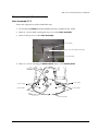
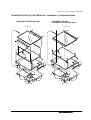
Chapter 9 Disassembly and Assembly
Disassembly and Assembly of the DM-M820 . . . . . . . . . . . . . . . . . . . . . . . . . . . . . . . . . . . . . . . . . . . . . . . . . . . .
Determining which procedure to use . . . . . . . . . . . . . . . . . . . . . . . . . . . . . . . . . . . . . . . . . . . . . . . . . . . . . . .
Precautions Before Assembly and Disassembly . . . . . . . . . . . . . . . . . . . . . . . . . . . . . . . . . . . . . . . . . . . . . . . . . .
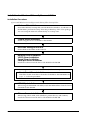
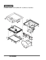
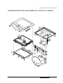
Conceptual Work Diagram for DM-M820 . . . . . . . . . . . . . . . . . . . . . . . . . . . . . . . . . . . . . . . . . . . . . . . . . . . . . . .
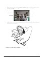
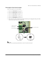
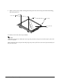
Disassembling the Base Assembly . . . . . . . . . . . . . . . . . . . . . . . . . . . . . . . . . . . . . . . . . . . . . . . . . . . . . . . . . . . . . .
Base Assembly(117) . . . . . . . . . . . . . . . . . . . . . . . . . . . . . . . . . . . . . . . . . . . . . . . . . . . . . . . . . . . . . . . . . . . . . .
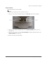
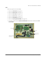
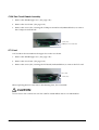
Removing the Covers . . . . . . . . . . . . . . . . . . . . . . . . . . . . . . . . . . . . . . . . . . . . . . . . . . . . . . . . . . . . . . . . . . . . . . . . .
Rear Cover . . . . . . . . . . . . . . . . . . . . . . . . . . . . . . . . . . . . . . . . . . . . . . . . . . . . . . . . . . . . . . . . . . . . . . . . . . . . . .
Front Cover . . . . . . . . . . . . . . . . . . . . . . . . . . . . . . . . . . . . . . . . . . . . . . . . . . . . . . . . . . . . . . . . . . . . . . . . . . . . .
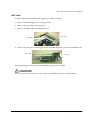
Removing the Components (SERIAL NO. *xxxx00xxxx*) . . . . . . . . . . . . . . . . . . . . . . . . . . . . . . . . . . . . . . . . . .
MSR Assembly or LED Circuit Board . . . . . . . . . . . . . . . . . . . . . . . . . . . . . . . . . . . . . . . . . . . . . . . . . . . . . . .
Rear Case . . . . . . . . . . . . . . . . . . . . . . . . . . . . . . . . . . . . . . . . . . . . . . . . . . . . . . . . . . . . . . . . . . . . . . . . . . . . . . .
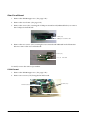
Removing the Front Case . . . . . . . . . . . . . . . . . . . . . . . . . . . . . . . . . . . . . . . . . . . . . . . . . . . . . . . . . . . . . . . . .
Rear panel . . . . . . . . . . . . . . . . . . . . . . . . . . . . . . . . . . . . . . . . . . . . . . . . . . . . . . . . . . . . . . . . . . . . . . . . . . . . . .
Touch Panel Circuit Board . . . . . . . . . . . . . . . . . . . . . . . . . . . . . . . . . . . . . . . . . . . . . . . . . . . . . . . . . . . . . . . .
LCD Circuit Board . . . . . . . . . . . . . . . . . . . . . . . . . . . . . . . . . . . . . . . . . . . . . . . . . . . . . . . . . . . . . . . . . . . . . . .
Inverter Circuit Board . . . . . . . . . . . . . . . . . . . . . . . . . . . . . . . . . . . . . . . . . . . . . . . . . . . . . . . . . . . . . . . . . . . .
Removing the Touch Panel Assembly . . . . . . . . . . . . . . . . . . . . . . . . . . . . . . . . . . . . . . . . . . . . . . . . . . . . . .
Removing the Touch Panel Unit . . . . . . . . . . . . . . . . . . . . . . . . . . . . . . . . . . . . . . . . . . . . . . . . . . . . . . . . . . .
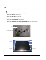
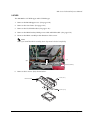
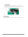
LCD . . . . . . . . . . . . . . . . . . . . . . . . . . . . . . . . . . . . . . . . . . . . . . . . . . . . . . . . . . . . . . . . . . . . . . . . . . . . . . . . . . .
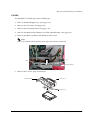
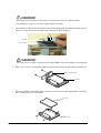
Switch Circuit Board . . . . . . . . . . . . . . . . . . . . . . . . . . . . . . . . . . . . . . . . . . . . . . . . . . . . . . . . . . . . . . . . . . . . .
Removing the Components (Later the SERIAL NO. *xxxx01xxxx*) . . . . . . . . . . . . . . . . . . . . . . . . . . . . . . . . . .
MSR Assembly or LED Circuit Board . . . . . . . . . . . . . . . . . . . . . . . . . . . . . . . . . . . . . . . . . . . . . . . . . . . . . . .
Rear Case . . . . . . . . . . . . . . . . . . . . . . . . . . . . . . . . . . . . . . . . . . . . . . . . . . . . . . . . . . . . . . . . . . . . . . . . . . . . . . .
Removing the Front Case . . . . . . . . . . . . . . . . . . . . . . . . . . . . . . . . . . . . . . . . . . . . . . . . . . . . . . . . . . . . . . . . .
Rear panel . . . . . . . . . . . . . . . . . . . . . . . . . . . . . . . . . . . . . . . . . . . . . . . . . . . . . . . . . . . . . . . . . . . . . . . . . . . . . .
Touch Panel Circuit Board . . . . . . . . . . . . . . . . . . . . . . . . . . . . . . . . . . . . . . . . . . . . . . . . . . . . . . . . . . . . . . . .
LCD Circuit Board . . . . . . . . . . . . . . . . . . . . . . . . . . . . . . . . . . . . . . . . . . . . . . . . . . . . . . . . . . . . . . . . . . . . . . .
Inverter Circuit Board . . . . . . . . . . . . . . . . . . . . . . . . . . . . . . . . . . . . . . . . . . . . . . . . . . . . . . . . . . . . . . . . . . . .
DC Jack Board . . . . . . . . . . . . . . . . . . . . . . . . . . . . . . . . . . . . . . . . . . . . . . . . . . . . . . . . . . . . . . . . . . . . . . . . . . .
Removing the Touch Panel Assembly . . . . . . . . . . . . . . . . . . . . . . . . . . . . . . . . . . . . . . . . . . . . . . . . . . . . . .
LCD . . . . . . . . . . . . . . . . . . . . . . . . . . . . . . . . . . . . . . . . . . . . . . . . . . . . . . . . . . . . . . . . . . . . . . . . . . . . . . . . . . .
Switch Circuit Board . . . . . . . . . . . . . . . . . . . . . . . . . . . . . . . . . . . . . . . . . . . . . . . . . . . . . . . . . . . . . . . . . . . . .
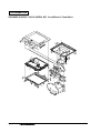
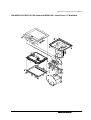
Disassembly and Assembly of the IM-800 . . . . . . . . . . . . . . . . . . . . . . . . . . . . . . . . . . . . . . . . . . . . . . . . . . . . . . .
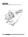
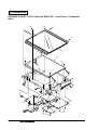
Conceptual Work Diagram for IM-800 . . . . . . . . . . . . . . . . . . . . . . . . . . . . . . . . . . . . . . . . . . . . . . . . . . . . . . . . . .
Removing the IM-800 Rear Case . . . . . . . . . . . . . . . . . . . . . . . . . . . . . . . . . . . . . . . . . . . . . . . . . . . . . . . . . . .
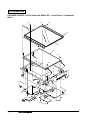
Removing the Covers . . . . . . . . . . . . . . . . . . . . . . . . . . . . . . . . . . . . . . . . . . . . . . . . . . . . . . . . . . . . . . . . . . . . . . . . .
IM-800 Upper Case . . . . . . . . . . . . . . . . . . . . . . . . . . . . . . . . . . . . . . . . . . . . . . . . . . . . . . . . . . . . . . . . . . . . . .
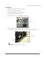
Removing the Compornents . . . . . . . . . . . . . . . . . . . . . . . . . . . . . . . . . . . . . . . . . . . . . . . . . . . . . . . . . . . . . . . . . . .
Riser Frame . . . . . . . . . . . . . . . . . . . . . . . . . . . . . . . . . . . . . . . . . . . . . . . . . . . . . . . . . . . . . . . . . . . . . . . . . . . . .
COM Port Circuit Board Assembly . . . . . . . . . . . . . . . . . . . . . . . . . . . . . . . . . . . . . . . . . . . . . . . . . . . . . . . . .
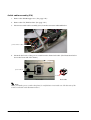
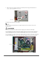
PCI Card . . . . . . . . . . . . . . . . . . . . . . . . . . . . . . . . . . . . . . . . . . . . . . . . . . . . . . . . . . . . . . . . . . . . . . . . . . . . . . .
RAID Card . . . . . . . . . . . . . . . . . . . . . . . . . . . . . . . . . . . . . . . . . . . . . . . . . . . . . . . . . . . . . . . . . . . . . . . . . . . . . .
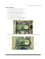
Riser Circuit Board . . . . . . . . . . . . . . . . . . . . . . . . . . . . . . . . . . . . . . . . . . . . . . . . . . . . . . . . . . . . . . . . . . . . . . .
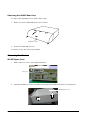
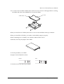
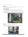
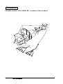
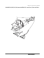
CD/FDD Bracket . . . . . . . . . . . . . . . . . . . . . . . . . . . . . . . . . . . . . . . . . . . . . . . . . . . . . . . . . . . . . . . . . . . . . . . .
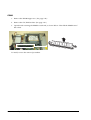
CD-ROM . . . . . . . . . . . . . . . . . . . . . . . . . . . . . . . . . . . . . . . . . . . . . . . . . . . . . . . . . . . . . . . . . . . . . . . . . . . . . . .
FDD . . . . . . . . . . . . . . . . . . . . . . . . . . . . . . . . . . . . . . . . . . . . . . . . . . . . . . . . . . . . . . . . . . . . . . . . . . . . . . . . . . .
HDD bracket . . . . . . . . . . . . . . . . . . . . . . . . . . . . . . . . . . . . . . . . . . . . . . . . . . . . . . . . . . . . . . . . . . . . . . . . . . . .
3.5”HDD . . . . . . . . . . . . . . . . . . . . . . . . . . . . . . . . . . . . . . . . . . . . . . . . . . . . . . . . . . . . . . . . . . . . . . . . . . . . . . .
2.5”HDD . . . . . . . . . . . . . . . . . . . . . . . . . . . . . . . . . . . . . . . . . . . . . . . . . . . . . . . . . . . . . . . . . . . . . . . . . . . . . . .
DIMM . . . . . . . . . . . . . . . . . . . . . . . . . . . . . . . . . . . . . . . . . . . . . . . . . . . . . . . . . . . . . . . . . . . . . . . . . . . . . . . . . .
System Fan . . . . . . . . . . . . . . . . . . . . . . . . . . . . . . . . . . . . . . . . . . . . . . . . . . . . . . . . . . . . . . . . . . . . . . . . . . . . .
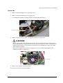
Switch cable assembly (218) . . . . . . . . . . . . . . . . . . . . . . . . . . . . . . . . . . . . . . . . . . . . . . . . . . . . . . . . . . . . . . .
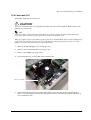
CPU Cooler and CPU . . . . . . . . . . . . . . . . . . . . . . . . . . . . . . . . . . . . . . . . . . . . . . . . . . . . . . . . . . . . . . . . . . . .
Speaker . . . . . . . . . . . . . . . . . . . . . . . . . . . . . . . . . . . . . . . . . . . . . . . . . . . . . . . . . . . . . . . . . . . . . . . . . . . . . . . . .
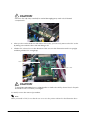
Power Supply . . . . . . . . . . . . . . . . . . . . . . . . . . . . . . . . . . . . . . . . . . . . . . . . . . . . . . . . . . . . . . . . . . . . . . . . . . .
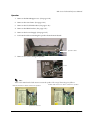
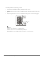
Main Circuit Board . . . . . . . . . . . . . . . . . . . . . . . . . . . . . . . . . . . . . . . . . . . . . . . . . . . . . . . . . . . . . . . . . . . . . . .
xvi
9-2
9-2
9-3
9-4
9-5
9-5
9-8
9-8
9-9
9-10
9-10
9-11
9-12
9-13
9-14
9-15
9-17
9-18
9-22
9-24
9-25
9-27
9-27
9-28
9-29
9-30
9-31
9-32
9-33
9-34
9-35
9-37
9-39
9-40
9-41
9-42
9-42
9-42
9-43
9-43
9-44
9-44
9-45
9-46
9-49
9-51
9-52
9-53
9-55
9-57
9-60
9-61
9-62
9-63
9-65
9-67
9-69
Rev. I
MR Series Technical Reference Manual
Appendix A Jumper Settings
IM-800 Jumper Settings . . . . . . . . . . . . . . . . . . . . . . . . . . . . . . . . . . . . . . . . . . . . . . . . . . . . . . . . . . . . . . . . . . . . . . .A-1
2.5”HDD Jumper Settings . . . . . . . . . . . . . . . . . . . . . . . . . . . . . . . . . . . . . . . . . . . . . . . . . . . . . . . . . . . . . . . . . . . . .A-1
DM-M820 Jumper Settings . . . . . . . . . . . . . . . . . . . . . . . . . . . . . . . . . . . . . . . . . . . . . . . . . . . . . . . . . . . . . . . . . . . . .A-2
Jumper settings for the touch panel board . . . . . . . . . . . . . . . . . . . . . . . . . . . . . . . . . . . . . . . . . . . . . . . . . . .A-2
LED of DM-M820 T/P board . . . . . . . . . . . . . . . . . . . . . . . . . . . . . . . . . . . . . . . . . . . . . . . . . . . . . . . . . . . . . . .A-2
Appendix B Parts Information
Part Life . . . . . . . . . . . . . . . . . . . . . . . . . . . . . . . . . . . . . . . . . . . . . . . . . . . . . . . . . . . . . . . . . . . . . . . . . . . . . . . . . . . . .B-1
Part List DM-M820-013/023/113/123 . . . . . . . . . . . . . . . . . . . . . . . . . . . . . . . . . . . . . . . . . . . . . . . . . . . . . . . . . . .B-2
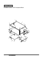
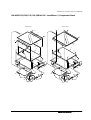
DM-M820-013/023/113/123 Case Block . . . . . . . . . . . . . . . . . . . . . . . . . . . . . . . . . . . . . . . . . . . . . . . . . . . . .B-3
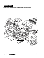
DM-M820-013/023/113/123 Component Block . . . . . . . . . . . . . . . . . . . . . . . . . . . . . . . . . . . . . . . . . . . . . . .B-4
DM-M820-013/023/113/123 Base Unit Block . . . . . . . . . . . . . . . . . . . . . . . . . . . . . . . . . . . . . . . . . . . . . . . . .B-5
Parts list DM-M820-014/024/114/124 (SERIAL NO. *xxxx00xxxx*) . . . . . . . . . . . . . . . . . . . . . . . . . . . . . . . . .B-6
DM-M820-014/024/114/124 (SERIAL NO. *xxxx00xxxx*) Case Block . . . . . . . . . . . . . . . . . . . . . . . . . . .B-8
DM-M820-014/024/114/124 (SERIAL NO. *xxxx00xxxx*) Component Block . . . . . . . . . . . . . . . . . . . . .B-9
DM-M820-014/024/114/124 (SERIAL NO. *xxxx00xxxx*) Base unit Block . . . . . . . . . . . . . . . . . . . . . . . .B-10
Parts list DM-M820-014/024/114/124 (Later the SERIAL NO. *xxxx01xxxx*) . . . . . . . . . . . . . . . . . . . . . . . . .B-11
DM-M820-014/024/114/124 (Later the SERIAL NO. *xxxx01xxxx*) Case Block . . . . . . . . . . . . . . . . . . .B-13
DM-M820-014/024/114/124 (Later the SERIAL NO. *xxxx01xxxx*) Component Block . . . . . . . . . . . . .B-14
DM-M820-014/024/114/124 (Later the SERIAL NO. *xxxx01xxxx*) Base unit Block . . . . . . . . . . . . . . .B-15
Parts list DM-M820-015/025/115/125 (SERIAL NO. *xxxx00xxxx*) . . . . . . . . . . . . . . . . . . . . . . . . . . . . . . . . .B-16
DM-M820-015/025/115/125 (SERIAL NO. *xxxx00xxxx*) Case Block . . . . . . . . . . . . . . . . . . . . . . . . . . .B-18
DM-M820-015/025/115/125 (SERIAL NO. *xxxx00xxxx*) Component Block . . . . . . . . . . . . . . . . . . . . .B-19
DM-M820-015/025/115/125 (SERIAL NO. *xxxx00xxxx*) Base unit Block . . . . . . . . . . . . . . . . . . . . . . . .B-20
Parts list DM-M820-015/025/115/125 (Later the SERIAL NO. *xxxx01xxxx*) . . . . . . . . . . . . . . . . . . . . . . . . .B-21
DM-M820-015/025/115/125 (Later the SERIAL NO. *xxxx01xxxx*) Case Block . . . . . . . . . . . . . . . . . . .B-23
DM-M820-015/025/115/125 (Later the SERIAL NO. *xxxx01xxxx*) Component Block . . . . . . . . . . . . .B-24
DM-M820-015/025/115/125 (Later the SERIAL NO. *xxxx01xxxx*) Base unit Block . . . . . . . . . . . . . . .B-25
Parts list (IM-800 for 3.5”HDD Model) . . . . . . . . . . . . . . . . . . . . . . . . . . . . . . . . . . . . . . . . . . . . . . . . . . . . . . . . . . .B-26
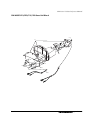
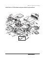
IM-800 for 3.5”HDD Model Component Block . . . . . . . . . . . . . . . . . . . . . . . . . . . . . . . . . . . . . . . . . . . . . . . .B-28
Parts list (IM-800 24V model) . . . . . . . . . . . . . . . . . . . . . . . . . . . . . . . . . . . . . . . . . . . . . . . . . . . . . . . . . . . . . . . . . . .B-29
IM-800 24V for 3.5”HDD Model and Speaker Model Component Block . . . . . . . . . . . . . . . . . . . . . . . . . .B-31
Parts list (IM-800 for 2.5”HDD Model and Speaker Model) . . . . . . . . . . . . . . . . . . . . . . . . . . . . . . . . . . . . . . . . .B-32
IM-800 for 2.5”HDD Model and Speaker Model Component Block . . . . . . . . . . . . . . . . . . . . . . . . . . . . . . . . . .B-34
Rev. I
xvii
xviii
Rev. I
MR Series Technical Reference Manual
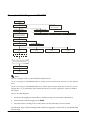
Chapter 1
Features and Overview
Features
The MR is a modular-type POS terminal consisting of a base unit, which is the IM-800, and a
display unit, which is the DM-M820. The IM-800 and the DM-M820 are also sold separately.
IM-800 Features
❏ IBM® PC/AT® compatible
❏ Intel® Celeron™ (FC-PGA/FC-PGA2 package) can be used. Either a 733 MHz or a 1.2 GHz
Celeron is factory installed.
❏ Two 168-pin DIMM sockets are ready for installation of a maximum 512 MB of memory
❏ An LCD unit (DM-M820) exclusive to the MR can be connected
❏ A 3.5-inch floppy disk drive is available
❏ A 3.5-inch hard disk drive or two 2.5-inch hard disk drive is available
❏ A CD-ROM drive or CD-R/RW drive is available as a factory option
❏ An Ethernet controller for 10Base-T/100Base-TX is installed as standard equipment
❏ Four serial interface ports are provided
❏ One PCI slot is provided
❏ A power supply for a TM printer is provided (For the 24V model)*1
❏ Cables on the rear of the IM-800 can be covered by the included cable cover
❏ A small footprint with maximum dimensions of 315 × 365 × 88 mm (W × D × H) {12.4 × 14.4
× 3.5"} (including rear cover)
*1 Applies only with the TM Printer Power Supply model.
DM-M820 Features
The DM-M820 is an LCD unit designed to be connected to an EPSON PC-POS system.
❏ 800 × 600 dots resolution using a 12.1 inch color TFT LCD
❏ A tilt mechanism for easy positioning of the screen viewing angle
❏ A cable cover or a unified cable performs cable management effectively
❏ Display settings of the LCD and the brightness of the backlight can be adjusted.
❏ A stain-resistant touch panel is used.*1
❏ Input by finger touch using the resistive film type of touch panel.*2
❏ An MSR unit can read ISO/JIS Track 1, 2, or 3 (only for models with an MSR unit) *3
Rev. I
Features and Overview 1-1
❏ Power is supplied from the IM-800 or the OI-MR01 AC Adapter. The AC Adapter is used if
the DM-M820 is bought by itself instead of with an IM-800.
*1 Applies only to models with a stain-resistant Touch Panel.
*2 Applies only to models with a Touch Panel.
*3 Applies only to models with an MSR, which is sold only with the IM-800.
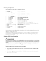
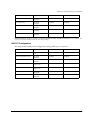
Model Configurations
The MR is composed of the IM-800 and the DM-M820.
IM-800
CPU
733MHz, 1.2GHz
HDD
One 3.5" HDD, Two 2.5" HDDs
CD-ROM drive
CD-ROM drive, CD-R/RW drive, Without
Power Supply
For the standardmodel
145W ATX Power supply
Power Supply
Withe the TM Printer
Power Supply model
180W ATX Power supply with 24V
Speaker
With, Without
Case Color
Epson cool white, Epson dark glay
DM-M820
MSR
With, Without
Touch Panel
With, Without
Back light
2 lights*
Case Color
Epson cool white, Epson dark glay
AC Adapter
With sold only the DM-M820 model
* The OLD model has 1 light.
The IM-800 and the DM-M820 are sold separately, but the DM-820 model with MSR is sold only
with the IM-800.
1-2 Features and Overview
Rev. I
MR Series Technical Reference Manual
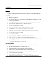
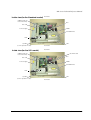
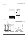
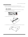
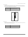
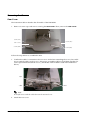
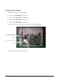
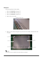
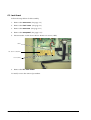
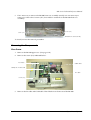
Part Names for IM-800
Front view
Ventilation
opening
USB ports
CD/FDD
cover
Power
switch
Power HDD LED
LED
With CD/FDD cover open
FDD LED
CD-ROM
drive(option)
Rev. I
CD-ROM CD-ROM
Eject FDD unit FDD eject
button
LED
eject button hole
Features and Overview 1-3
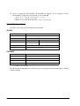
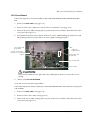
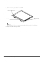
Rear Cover
Rear cover
Rear view(Standard model)
Mouse
COM1 port
Keyboard
LPT port
PCI slot COM3 port
COM2 port
Display
port
Line-out
output
DC 12V output
(for DM-M820)
Line-in Mic input
input
Ethernet
port
USB port
AC voltage
select switch
AC Inlet
COM4 port
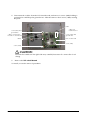
Rear view(24V model)
DC 24V output
(for TM printer)
Mouse
Keyboard
PCI slot COM3 port
COM2 port
DC 12V output
COM1 port
LPT port
1-4 Features and Overview
Display
port
Line-out
output
Ethernet
port
USB port
Line-in Mic input
input
AC Inlet
COM4 port
Rev. I
MR Series Technical Reference Manual
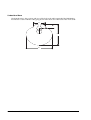
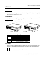
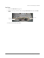
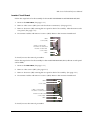
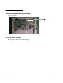
.
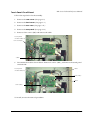
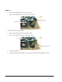
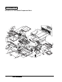
Inside view(for the Standard model)
Rear Side
COM Port Circuit
Board Assembly
CPU
PCI card
DIMM
Power Supply
CD-ROM Drive
HDD
FDD
Speaker
(for the Speaker model)
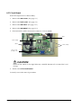
Inside view(for the 24V model)
Front Side
Rear Side
COM Port Circuit
Board Assembly
DC 24V Board
CPU
PCI card
DIMM
Power Supply
CD-ROM Drive
HDD
FDD
Speaker
(for the Speaker model)
Rev. I
Front Side
Features and Overview 1-5
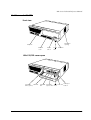
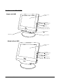
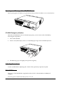
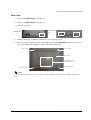
Part Names for DM-M820
Model with MSR
LCD / touch
panel*
Function
control buttons
Adjustment
control
Power switch
Power-On LED
Card Slot**
MSR unit**
LED for MSR**
Model without MSR
LCD / touch
panel*
Function
control buttons
Adjustment
control
Power switch
Power-On LED
1-6 Features and Overview
Rev. I
MR Series Technical Reference Manual
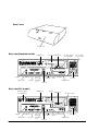
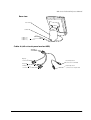
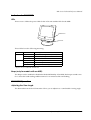
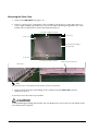
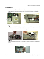
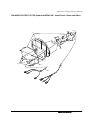
Rear view
LCD stand
Stand tab
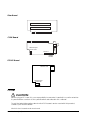
Cable A /
Cable B /
Cable C /
Cable A (with a touch panel and an MSR)
Display
connector
DC plug
Serial port
connector
Rev. I
PS/2 keyboard
connector for IM-800
PS/2 keyboard
connector for keyboard
Features and Overview 1-7
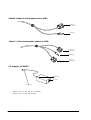
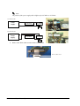
Cable B (without a touch panel and an MSR)
Display
connector
DC plug
Cable C (with a touch panel, without an MSR)
Serial port
connector
DC plug
Display
connecter
.
AC Adapter (OI-MR01)
Power LED
AC inlet
DC plug
* Applies only to models with a touch panel.
** Applies only to models with an MSR.
1-8 Features and Overview
Rev. I
MR Series Technical Reference Manual
Specifications
IM-800
Item
CPU
Memory
Usable CPU types *1)
Celeron 733 MHz or 1.2 GHz
Socket
370-pin socket
Main memory *2)
168-pin DIMM slots × 2
3.3V PC100 SDRAM / Maximum 512MB
BIOS ROM
512KB
Chipset
Intel 810E2 chipset
Video controller
Built-in chipset
IO controller
Winbond W83627F (controls FDD, COM1/2, PS/2, and parallel
interface)
ITE IT8872F (controls COM3/4)
Mass storage
FDD
One 3.5" floppy drive (1.44MB / 720KB)
HDD
One 3.5" HDD or Two 2.5" HDD
IDE interface / Ultra DMA/33/66/100
CD-ROM drive
A CD-ROM or CD-R/RW optionally installed in factory, IDE
interface, can be set as boot drive
Interface
LAN (Ethernet)
10BASE-T/100BASE-TX is installed, "Wake On LAN" is
supported.
Interface
Keyboard
One PS/2-type (6-pin mini-DIN)
Mouse
One PS/2-type (6-pin mini-DIN)
Serial *3)
Four ports (9-pin D-sub male)
+5V or +12V can be output to COM3 or COM4.
Parallel
One port (D-sub 25-pin female) SPP/EPP/ECP supported
Display
One port (D-sub 15-pin female)
USB *4)
Two ports on the front and two ports on the rear.
Audio
LINE IN, LINE OUT, microphone terminals
DC12V output *5) *8)
One (+12V / 3A) for DM-M820
DC 24V output*8)
One (+24V / 2A) for EPSON TM Printer
PCI slot
One slot (PCI version 2.2 compliant)
Expansion slot
Rev. I
Specifications
Internal speaker *6)
Built-in monaural speaker
Audio function *6)
AC'97 audio CODEC supported
External line input/output, with a microphone terminal
Backup battery
For the Lithium non-rechargeable battery the RTC and the
RTC's built-in CMOS RAM when AC power is not supplied.
Battery type: CR2032
Battery life: Approximately 5 years
BIOS
ACPI 1.0b / APM 1.2 / Plug & Play / DMI
Diagnostics Utility are supported
OS *7)
MS-DOS, Windows 98, Windows NT, Windows 2000, Windows XP
Features and Overview 1-9
Item
Specifications
Lithium battery
Power supply
The IM-800 is internally equipped with a Lithium non-rechargeable
battery that supplies the backup voltage to the RTC and the RTC's builtin CMOS RAM when AC power is not supplied. The battery can be
exchanged easily because the battery is connected through the
socket.
Battery type: CR2032
Battery life: Approximately 5 years
Standard
model
24V
model
Case
Environmental
conditions
145W ATX power supply is built in
Input voltage *8)
AC input voltage can be changed with a switch.
Low range: 100-127 VAC / 3.5 A (max.)
High range: 200-240 VAC / 2 A (max.)
Frequency
50 / 60 Hz
180W ATX power supply is built in
Input voltage *8)
100-127 VAC / 4 A (max.)
200-240 VAC / 2 A (max.)
Frequency
50 / 60 Hz
Size
315(W) × 280(D) × 88(H) mm (excluding the rear cover)
{12.4 × 11 × 3.5"}
315(W) × 365(D) × 88(H) mm (including the rear cover)
{12.4 × 14.4 × 3.5"}
Color
Epson cool white
Epson dark gray
Condition:
Operating range
Temperature: 5 to 35°C {41 to 95°F}
Humidity (RH): 30 to 80% non-condensing
Storage range
–10 to 50°C {14 to 122°F}
30 to 90% non-condensing
*1: The Celeron (533 MHz or less) with a PPGA package is not supported.
*2: ECC is not supported.
*3: If the COM3/4 is used, you need to install the serial driver from the Driver CD-ROM for the IM-800.
*4: The USB interface is not supported with MS-DOS, or Windows NT. (The keyboard or mouse is supported with the BIOS.)
*5: The LCD outlet must not be connected to a peripheral other than the DM-M820.·
*6: The internal speaker is not supported by the onboard sound controller.(There is a model that can output sound through the
internal speaker.)
*7: There are some limitations with each OS. Refer to Chapter 4 “OS and Drivers.”
*8: A switch to cut the AC power off is not available.
1-10 Features and Overview
Rev. I
MR Series Technical Reference Manual
DM-M820
Item
LCD
Backlight
Specification
Size
12.1"
Type
Color TFT
Resolution
800 × 600 dots
Color
262,144 colors
(Can emulate 16 M color display using the dithering
function)
Input signal
0.7V p-p, 75 ohm
Scanning frequency
Horizontal 24 to 69KHz, Vertical 50 to 85 Hz
Dot clock frequency
Max. 80MHz
View angle
Horizontal
direction
From the left 45º (typ.) to the right 45º (typ.)
Vertical direction
From the top 30º (typ.) to the bottom 10º (typ.)
Number of lamps
1 lamp
Brightness
150 cd/m2 min. (except touch panel)
100 cd/m2 min. (including touch panel)
Life
20,000 hours or more (at 25 ± 5°C {77 ± 9°F})
Initial brightness reduced to half
Number of lamps
2 lamp
Brightness
275 cd/m2 min. (except touch panel)
Life
50,000 hours or more (at 25 ± 5°C {77 ± 9°F})
Initial brightness reduced to half
Old Backlight
Standard model
Backlight
Standard model
(Old Backlight
High brightness
model)
Touch panel*1
MSR*2
Method
Resistive film (touch with finger)
Surface solidity
3H or more (JIS K-5400)
Positioning accuracy
±1.5 % maximum
Supported cards
ISO 7811, JIS X6301 Type I tracks 1, 2, 3
Reading direction
Bidirectional
Supporting MSR firmware
Ver 3.04 or later
External interface
Indicator
Rev. I
DC Jack, Serial port connector*1, Display connector,
PS/2 connectors × 2 (for a PS/2 keyboard and the IM800)*2
With an MSR
POWER LED, LED for MSR
Without an MSR
POWER LED
AC Adapter
POWER LED
Power supply
+12V (supplied through the DC cable from the IM-800
or AC Adapter OI-MR01)
Tilting angle
From 0º to 90º
Case color
Epson cool white
Epson dark gray
Dimensions
320 × 340 × 200 mm (W × H × D) {12.6 × 13.4 × 7.9"}
Features and Overview 1-11
Item
Specification
Mass
Approximately 5.0 kg {3.3 lb}
Environmental conditions
Condition:
Operating range
Storage
range
Temperature: 5 to 35°C {41 to 95°F}
–10 to 50°C
{14 to 122°F}
Humidity (RH): 30 to 80% non-condensing 30 to 90%
non-condensing
The unit is not water resistant.
Others
Connection to the IM-800 through an exclusive DC
cable.
A button on the right side of the panel lets you adjust
the backlight brightness.
*1 Applies only to models with a touch panel.
*2 Applies only to models with an MSR unit.
AC Adapter (OI-MR01)*
Item
Specification
Input
90 -264 VAC / 1.5 A (max.)
Frequency
47 -63 Hz
Output
12VDC / 3 A (max.)
Protection
function
Over voltage protection
function
Built-in
Circuit breaker
Manual reset
Dimensions
110 × 62 × 33 mm (W × H × D) {4.3× 2.4 × 1.3"}
* The AC Adapter is used if the DM-M820 without MSR model is used without an IM-800.
1-12 Features and Overview
Rev. I
MR Series Technical Reference Manual
Dimensions
IM-800
Dimensions:
315 (W) × 280 (D) × 88 (H) mm {12.4 × 11 × 3.5"} (excluding the rear cover)
365
280
315 (W) × 365 (D) × 88 (H) mm {12.4 × 14.4 × 3.5"} (including the rear cover)
88
(excluding the rubber feet)
[Units : mm]
315
DM-M820
340 mm
250 mm
200 mm
305 mm
Rev. I
320 mm
Features and Overview 1-13
Underside of Base
The dotted circle is the position and size of the hole in the table required if the DM-M820 is
mounted on a table with the cable going down rather than out of the back of the LCD stand.
102
70
50
200
240
1-14 Features and Overview
Rev. I
MR Series Technical Reference Manual
Chapter 2
Setup for the IM-800 and the DM-M820
Setting the AC Voltage for the IM-800 (For the Standard model)
If you are using 100-127 V power, set the AC
voltage switch to 115. If you are using 200-240 V
power, set the AC voltage switch to 230. (The
factory setting is 230.) If the setting is wrong,
the system will be damaged and will not
operate.
Follow these steps:
1. Remove the warning sheet.
2. Set the AC voltage select switch.
IM-800 Installation Positions
You can install the unit in either of the positions shown.
The rubber feet are used only when the unit is installed
horizontally. Attach the rubber feet to the indentations on
the bottom of the unit.
WARNING:
If you set this product upright, be sure the ventilation opening is on the top. Do not place
any object on top of the ventilation opening. If the ventilation opening is blocked, the
product can be damaged by overheating.
If you install this product horizontally, never place any object within 3 cm {1.2"} of the
ventilation openings on the front, side, and rear. If the ventilation opening is blocked,
the product can be damaged by overheating.
Rev. I
Setup for the IM-800 and the DM-M820 2-1
If the IM-800 is placed horizontally with the rear cover installed, attach the rubber feet
that are included or leave at least 1 cm {0.4"} of space from the bottom of the rear
cover.
1cm or more
Installing face
Do not put anything that weighs more than 20 kg {44 lb} on the IM-800 when it is installed
horizontally.
Installing the DM-M820
Cable Arrangement
When you plan your installation of the DM-M820, consider the cable that comes out of the base.
There are two ways you can arrange the cable:
❏ Make a hole in the surface on which you will place the unit and run the cable through the
hole (A in the illustration below).
❏ Remove the tab from the back of the LCD stand and run the cable out of the back of the LCD
stand (B in the illustration below).
B
A
CAUTION:
If burrs are left after the tabs are removed, they may cause cuts or scratches. Remove
the burrs with a nipper or file.
2-2 Setup for the IM-800 and the DM-M820
Rev. I
MR Series Technical Reference Manual
Connecting the DM-M820
Be sure to unplug the power cable for the IM-800 or PC before you connect the cables for the
DM-M820.
Connectors on the IM-800
Serial port connectors
DC plug
Keyboard out
Display connector
Connector Cables for a DM-M820 with a Touch Panel and MSR
❏ DC plug
Connects to the 12 VDC output of the IM-800.
❏ Display connector
Connects to the display port of the IM-800.
❏ Serial port connector Connects to the touch panel COM1 or COM2 port.
Note:
If you are using a DM-M820 with a touch panel, be sure to connect the serial port connector to
COM1 or COM2. Do not use COM3 or COM4.
Also if you are using a DM-M820 with a touch panel, do not install a mouse driver. Installing a
mouse driver can prevent the touch panel from working.
❏ Keyboard out
Connects the keyboard out to the IM-800 keyboard port.
Note:
Be sure not to connect to the mouse port.
❏
Keyboard in
If you are using an external PS/2 keyboard, connect it to the keyboard
in connector.
Connector Cables for a DM-M820 with a Touch Panel and without an MSR
❏ DC plug
Connect to the 12 VDC output on the IM-800 or the AC adapter
(OI-MR01).
❏ Display connector
Connect to the display port on the IM-800 or PC.
❏ Serial port connector Connect to the COM port for the touch panel on the IM-800 or PC.
Rev. I
Setup for the IM-800 and the DM-M820 2-3
Note:
If you are using a DM-M820 with a touch panel, be sure to connect the serial port connector to
COM1 or COM2. Do not use COM3 or COM4.
Also if you are using a DM-M820 with a touch panel, do not install a mouse driver. Installing a
mouse driver can prevent the touch panel from working.
Connector Cables for a DM-M820 with No Touch Panel and No MSR
❏ DC plug
❏ Display connector
Connect to the 12 VDC output of the IM-800 or AC adapter
(OI-MR01).
Connect to the display port of the IM-800 or PC.
Connecting the Power Cable for AC Adapter
Be sure to push the end of the power cable all the way into the AC inlet. The fitting on the power
cable should make contact with the back of the inlet.
CAUTION:
Do not use the DC plug on a system other than the IM-800 or the OI-MR01 (AC adapter).
The DC plug on the exclusive cable is designed only for the IM-800 or the OI-MR01 (AC
adapter).
IM-800 Connectors
The illustration below shows all the connectors on the back of the IM-800. In addition, there are
two USB connectors on the front. (See Chapter 1.)
Be sure to unplug the power cable from the IM-800 before you connect these cables.
Standard model
PCI slot COM3
COM2
Mouse
Keyboard
Line-out
Display
COM1
LPT
Ethernet
12 VDC output
for DM-M820
Line-in Mic input
AC Inlet
COM4
USB
2-4 Setup for the IM-800 and the DM-M820
Rev. I
MR Series Technical Reference Manual
With the TM Printer Power Supply model
PCI slot COM3
COM2
Mouse
Keyboard
Display
COM1
LPT
Line-out
12 VDC output
for DM-M820
Line-in Mic input
Ethernet
AC Inlet
COM4
USB
Connecting Other Peripheral Devices to the IM-800
These are general instructions for the types of peripherals you may want to use.
CAUTION:
The12 VDC output is an exclusive power supply for the DM-M820. Do not use it for other
peripheral devices.
Serial Device Information
If you use COM3 or COM4, you must install the serial driver from the driver CD-ROM for the
IM-800, included with the IM-800.
Either + 5 V or +12 V can be output to COM3 or COM4. See Appendix A, “Jumper Settings.”
Connecting a Serial Modem to the IM-800
If you are using a serial modem with the IM-800, be sure to connect the modem to COM1 or
COM2. Do not use COM3 or COM4.
USB Device Information
There are four USB ports, two on the front and two on the back.
You cannot use USB devices if you are using either MS-DOS or Windows NT.
Rev. I
Setup for the IM-800 and the DM-M820 2-5
Keyboard and Mouse
To use a USB keyboard or mouse under MS-DOS or Windows NT, set USB keyboard support or
USB mouse support in the Integral Peripheral section of the BIOS setup.
Using a PS/2 mouse
To use a PS/2 mouse, you must be sure that USB mouse support in the Integrated
Peripheral section of the BIOS is set to Disabled (which is the factory setting).
TM-Printer
Use the dedicated power supply for the power supply of the TM-Printer. (For the standard
model)
Connect the power supply of the TM-Printer to the DC24V Output using the DC cable. (For the
24V model)
PCI Cards
See the PCI information in Chapter 3, “Hardware Specifications,” and Chapter 9, “Disassembly
and Assembly.”
Connecting the Power Cable
When AC power is supplied, a minute electric current flows through the IM-800. Therefore,
before connecting peripherals and cables to this product, unplug the AC cord.
WARNING:
Never insert or disconnect the power plug with wet hands. Doing so may result in severe
shock.
Always supply power directly from a standard domestic power outlet.
Do not place multiple loads on the power outlet (wall outlet). Overloading the outlet
may lead to fire.
The equipment must be installed near the electrical outlet, and the outlet must be easily
accessible.
Be sure your power cable meets the relevant safety standards and includes a power
system ground terminal (PE terminal).
2-6 Setup for the IM-800 and the DM-M820
Rev. I
MR Series Technical Reference Manual
Attaching the Rear Cover
The rear cover makes the back of the system look neat and protects the cables.
1. When you want the cables to exit the top of the rear cover, use pliers to break out the tabs.
CAUTION:
If burrs are left after the tabs are removed, they may cause cuts or scratches.
Remove the burrs with a cutter or file.
2. Remove the screw from the lower right corner of the back of the unit.
3. Fit the tabs on the rear cover as shown below.
tabs
4. Attach with three screws, including the one you removed, in the locations shown below.
Rev. I
Setup for the IM-800 and the DM-M820 2-7
2-8 Setup for the IM-800 and the DM-M820
Rev. I
MR Series Technical Reference Manual
Chapter 3
Hardware Specifications
Hardware Block Diagram for IM-800
Main Board
I2C Bus
Clock
Generator
ICS9248-9
6
66/100/133 MHz
CPU
Socket 370
S-DRAM
PC100
DIMM 168
Pins X 2
810E
GMCH
(North Bridge)
82810E
VRM 8.5
DC/DC
ISL6524
HDD Power
FDD Power
CD Power
DC Jack Power
ATX Power
Supply Unit
HOST Bus
ATX 20 Pins
Power Connector
VGA
CRT
Power Button
Power/HDD LED
Hub Link
BOX Header
USB Port 0
USB
I2C Bus
ICH2
(South Bridge)
FW82801BA
RTC
Battery
Rear
USB Port 1
USB
USB Port 2
RJ-45
& LED
PHY
82562ET
MAC
MIC
L_Out
L_In
CODEC
AD1887
AC Link
Front
USB
PCI Bus
PCI Bus
Riser Board Slot
ATA-33/66/100
Primary IDE
FWH (BIOS)
Firmware Hub
512K Byte
49LF004
/ 82802AB
USB
Pin
Header
USB Port 3
Secondary IDE
Riser Board
1st IDE
2nd IDE
Standard
PCI Slot
Low Profile
PCI Slot
SPKR
FWH
COM Board
+12V
LPC Interface
Keyboard
Mouse
PS-2 Keyboard
LPC
Winbond
Floppy
COM2
COM 1
COM 2
QFP-128
Parallel
FDD
IT8872F
+12V
+5V
COM 4
LPT
CPU Fan
System Fan
Rev. I
COM 3
ITE
PCI
Bridge
Beep
W83627F
COM1
+5V
Speaker
Super I/O
PS-2 Mouse
24V
Output
+12V
DC
Jack for
LCD
Hardware Specifications 3-1
DMA
The IM-800 supports seven DMA channels. Channels 0, 1, 2, and 3 provide 8-bit data transfers;
channels 4, 5, 6, and 7 provide 16-bit data transfers. The IM-800 uses channel 2 for the floppy
disk drive controller and releases the other channels to the other devices. The following table
lists the DMA channel allocation.
DMA channels
Controller
Channel
DMA1 8 bits
DMA2 16 bits
Application
0
(Spare)
1
(Spare*)
2
Floppy disk drive controller
3
(Spare*)
4
Controller 1 cascade
5
(Spare)
6
(Spare)
7
(Spare)
* When LPT1 is in ECP mode, use one of these channels.
System Interrupts
The system connects 2 8259A-equivalent interrupt controllers in cascade and has 15 levels of
interrupts, besides NMIs. The following table shows the application for each interrupt. Change
the system interrupts with the BIOS setup program or Plug & Play function.
System interrupts
Controller 1
Application
Changeable?
IRQ0
Controller 2
Timer
NO
IRQ1
Keyboard
NO
IRQ2
Controller 2 cascade
NO
RTC
NO
IRQ8
IRQ9
1
Not used *
OK
IRQ10
Not used *1
OK
IRQ11
Not used *1
OK
IRQ12
Mouse
NO
IRQ13
Numerical operation coprocessor
NO
IRQ14
IDE controller (primary)
*2
IRQ15
IDE controller (secondary)
*2
IRQ3
Serial port 2
OK
IRQ4
Serial port 1
OK
IRQ5
Not used *1
OK
IRQ6
Floppy disk controller
NO *3
IRQ7
Parallel port 1
OK
NMI
I/O error check
NO
*1 PCI (for example, network) is automatically set through the detection of the unused interrupt level. If Serial port 3/
4 is used with Windows, use an unused interrupt level. If Serial port 3/4 is used with DOS, Serial port 3 is set to IRQ11
and Serial port 4 is set to IRQ10 automatically.
*2 Changes are not possible when the device is in use, but can be cleared when not in use.
*3 This can be set to “Not used” in the BIOS setup, but the IRQ is not released.
3-2 Hardware Specifications
Rev. I
MR Series Technical Reference Manual
Configuration of Circuit Boards
Main Board
CPU Fan
Connector
System Fan
Connector
Mouse
Keyboard
Power Switch
Connector
LED
Connector
ATX Connector
BIOS
Parallel
COM1
CRT
Line-Out
COM2
Header
Line-In
Mic-In
Primary IDE
LAN
USB x2
Secondary IDE
DIMM Sockets
FDD
CPU
Socket
(370-pin)
CD Audio
Header
Front USB
Header
JP15
JP10
Riser Card Slot
Speaker
Connector
Speaker
RTC Battery
COMS CLEAR Jumper
Rev. I
Hardware Specifications 3-3
Riser Board
PCI Slot
COM Board Slot
DC12V
Jack
COM Board
COM3
DC12V Input
Connector
JP2 JP1
COM4
Header
DC24V Board
DC24V Jack
DC24V Input
Connector
PCI Slot
CAUTION:
Before using a PCI card, it is your responsibility to examine it carefully to confirm whether
its specifications conform to the specifications described in this manual.
To get the latest information about which PCI board can be used with this product,
contact your EPSON dealer.
The PCI slot is located on the riser board.
3-4 Hardware Specifications
Rev. I
MR Series Technical Reference Manual
The dimensions of installable PCI cards are shown below:
210
<Part mounting face>
106.68
Maximum height of parts: 14.48
(maximum)
Maximum height of parts on the soldering face:
2.67 (maximum)
[Units:mm]
Power Supply
The IM-800 has an ATX power supply that switches the AC input by AC voltage select switch
and does not have a switch to cut off the AC input.
Standard model
Input voltage:
Low range 100 - 127 VAC (90 - 137 VAC)
High range 200 - 240 VAC (180 - 265 VAC)
Input frequency:
50 ± 3 Hz / 60 ± 3 Hz
Input current:
3.5 A maximum (100 - 127 VAC)
2 A maximum (200 - 240 VAC)
Cooling fan:
Air intake type, fan rotation speed is automatically changed, depending on
the temperature in the power supply unit.
MTBF:
200,000 hours
Precautions:
1) Setting the AC input voltage switch improperly causes the following problems:
If you use 100-127 V power when the switch is set to 230, the IM-800 will not operate, but if you
change the setting to 115, the unit will operate.
If you use 200-240 V power when the switch is set to 115, the voltage power unit will be
damaged.
2) When the protective circuit of the voltage power unit performs a shutdown, the protective
circuit keeps working for a while. When this happens, unplug the power cable and wait for
about 15 seconds; then plug the cable back in.
Rev. I
Hardware Specifications 3-5
24V model
Input voltage/current:
100 - 127 VAC / 4A
200 - 240 VAC / 2A
Input frequency:
50 ± 3 Hz / 60 ± 3 Hz
Cooling fan:
depending on
Air intake type, fan rotation speed is automatically changed,
the temperature in the power supply unit.
MTBF:
200,000 hours
Precautions:
2) When the protective circuit of the voltage power unit performs a shutdown, the protective
circuit keeps working for a while. When this happens, unplug the power cable and wait for
about 15 seconds; then plug the cable back in.
Power supply capacity for external devices
Total power available to devices connected to the interface boards in the PCI slot, COM3/4,
keyboard/mouse, and USB are as follows. Current drain must not exceed the capacity shown
for each supply voltage: +5V, +3.3V, +12V, and -12V.
Power supply
Used for
Capacity
+5 VDC
PCI slot, COM ports, keyboard/mouse, USB
2.0 A
+3.3 VDC
PCI slot
1.0 A
+12 VDC
PCI slot, COM ports
1.0 A
-12 VDC
PCI slot
0.02 A
Each port has the following current limitation:
Power Supply Capacities to Each Port
Port
Voltage
Current supply capacity
Remarks
COM port
+5 VDC
500 mA each (peak 1 A/100 ms)
+12 VDC
500 mA each (peak 1 A/100 ms)
Total current of +5
VDC and +12 VDC
must not exceed the
value shown at left.
USB port
+5 VDC
500 mA each (peak 1 A/100 ms)
--
Keyboard and mouse
+5 VDC
500 mA (peak 1A / 100 ms)
--
2A (peak 1A / 100 ms)
--
Power Supply for 24V model +24 VDC
3-6 Hardware Specifications
Rev. I
MR Series Technical Reference Manual
Lithium Battery
The IM-800 is internally equipped with a Lithium non-rechargeable battery, which supplies the
backup voltage to the RTC and the RTC's built-in CMOS RAM (only when the AC power is not
supplied). The battery can be exchanged easily because the battery is connected through the
socket.
Battery type:
CR2032
Vendor:
Sony, Maxell, Toshiba
Battery life:
Approximately 5 years
When replacing batteries, be sure to use the types and manufacturers listed above.
MAC Address
The MAC address label is attached on the LPT connector of the main board.
Rev. I
Hardware Specifications 3-7
3-8 Hardware Specifications
Rev. I
MR Series Technical Reference Manual
Chapter 4
OS and Drivers
Outline of This Chapter
This chapter tells which Operating Sytems and Drivers can be used and how to install and
uninstall them.
CAUTION:
Don’t write anything, such as an application to an HDD that is removed from the MR.
The vibration and impact can cause trouble and the failure of the HDD.
Operating Systems
The following Operating Systems can be used for the IM-800.
❏ Windows 2000 Professional (There is a version preinstalled by EPSON)
❏ Windows XP Professional
❏ Windows 98SE
(There is a version preinstalled by EPSON)
❏ Windows NT Workstation 4.0 SP6a
❏ MS-DOS Ver.6.22
Drivers and Utilities
Drivers for using the IM-800 are on the Driver CD-ROM included with the IM-800. If the
operating system is pre-installed, the drivers are also installed.
MSR utilities for the DM-M820 with MSR are on the Driver CD-ROM included with the IM-800,
and if the operating system is pre-installed, the utilities are on the HDD. Set up the MSR using
the utilities.
Touch panel drivers for the DM-M820 with touch panel are on the touch panel driver CD-ROM
for the DM-M820. Even if the operating system is preinstalled, you must install the touch panel
drivers.
Rev. I
OS and Drivers 4-1
Driver CD-ROM for the IM-800
The driver for installing a locally procured OS on the IM-800, the MSR utility for using the MSR
of the DM-M820, and drivers for using the peripheral devices are on this CD-ROM.
The CD-ROM directory is shown below.
Root
|--- DOS62
|
|--- Cdrom
|
|--- Network
|
|--- Serial
|--- WIN98
|
|--- Chipset
|
|--- Network
|
|--- Serial
|
|--- Sound
|
|---Video
|--- WINNT
|
|--- Network
|
|--- Serial
|
|--- Sound
|
|---Video
|--- WIN2K
|
|--- Chipset
|
|--- Network
|
|--- Serial
|
|--- Sound
|
|---Video
|--- WINXP
|
|--- Serial
|--- COMMON
|--- Apdrv
|--- Oposadk
|--- TmDrv
|--- MSRCFG
|--- WIN
|--- DISK1
|--- DOS
:
:
:
:
:
:
:
:
:
:
:
:
:
:
:
:
:
:
:
:
:
:
:
:
:
CDVER.TAG
Drivers for MS-DOS
CD-ROM drivers
Network drivers
Serial drivers
Drivers for Windows98
Chipset drivers
Network drivers
Serial drivers
Sound drivers
Video drivers
Drivers for Windows NT
Network drivers
Serial drivers
Sound drivers
Video drivers
Drivers for Windows2000
Chipset drivers
Network drivers
Serial drivers
Sound drivers
Video drivers
Drivers for Windows XP
Serial drivers
Common OS utility drivers
Advanced Printer Drivers
OPOS-ADK
UniMini Drivers
DM-MS Definition tool
Readme.txt files are in both the root directory and in subdirectories of the root directory.
1. The Readme.txt file in the root directory contains an overview of this CD-ROM, and
refers to the Readme.txt files in the various subdirectories.
2. The Readme.txt files in the operating system subdirectories explain driver installation/
un-installation for each operating system.
3. Readme.txt files for MSRCFG, OPOS-ADK, and APDRV are included with the software.
4-2 OS and Drivers
Rev. I
MR Series Technical Reference Manual
Touch Panel driver CD-ROM for the DM-M820 touch panel model
The CD-ROM directory is shown below.
Root
|--- DOS
|--- WIN--- European
|--- Asian
CDVER.TAG
Touch Panel Driver for MS-DOS
Touch Panel Driver for Windows98/NT/2000/XP for European
Touch Panel Driver for Windows98/NT/2000/XP for Chinese T/
C,Korean
Readme.txt files are in both the root directory and in subdirectories beneath the root directory.
1. The Readme.txt file in the root directory contains an overview of this CD-ROM, and
refers to the Readme.txt files in the various subdirectories.
2. The Readme.txt files under the operating system subdirectories explain driver
installation/un-installation for each operating system.
Rev. I
OS and Drivers 4-3
Windows 2000 Pre-Installed Model
The exclusive EPSON utility and drivers for using IM-800 are pre-installed in the HDD with the
pre-installed Windows 2000 Professional.
Installation Procedure
Windows 2000 Installation
When turning on the power supply, the installation starts. Enter the product
key of the W2K label pasted on the product. You can set up the Network
automatically or set it up later.
When using the DM-M820 with Touch Panel, follow the steps as below.
Touch Panel Driver Installation
Install the Touch Panel Driver from the CD-ROM for the DM-M820. See
page 4-45 for the procedure.
Change of Double click settings
Set up this setting every time a new user starts using Windows 2000.
MSR Utility Installation
When using the DM-M820 with MSR, install the MSR utilities from
C:\backup\msrcfg folder or the Driver CD-ROM for the IM-800.
Other software Installation
When using OPOS-ADK, APD (Windows printer drivers) and Unimini,
install the software from the Driver CD-ROM for the IM-800.
Formatting the hard disk
The hard disk is composed of one partition of up to 10 GB as a system area. For a hard disk of
more than 10 GB, the excess area other than the system area, is not yet formatted. This drive can
be converted to NTFS using the Convert command. Use the disk administrator when creating a
drive in the unused area. The start-up drive has been formatted to the following file system.
•
File system: FAT32
•
Volume label: Windows 2000
4-4 OS and Drivers
Rev. I
MR Series Technical Reference Manual
Pre-installed software
❏ Microsoft Windows 2000 Professional
❏ Microsoft Windows 2000 Service Pack 2
❏ Multilingual User Interface (French, German, Italian, Spanish, Dutch, Portuguese)
❏ Intel Chipset software installation utility
❏ Intel Video driver
❏ Intel Network driver
❏ Analog Devices Sound driver
❏ ITE COM3/4 Driver
❏ EPSON DM-MS Series setup utility *1
Version of the Pre-installation HDD
To confirm the version of the HDD, see the file HDVER.TAG at the root directory of the boot
drive. This file is text-formatted and can be read using Notepad or a similar text editor. The file
HDVER.TAG has the following contents:
[HD Information]
MODEL=IM-800
OS=Windows2000
LANG=Dutch/English/French/German/Italian/Portuguese/Spanish
VER=1.**.*
Rev. I
OS and Drivers 4-5
Directory Configuration
The root directory of the HDD is structured as follows.
|--- Backup
|
|--- Msrcfg
:
|
|
|--- Win
:
|
|
|
|--- Disk1 :
|
|
|--- DOS
:
|
|--- Chipset
:
|
|
|--- Win2000
:
|
|--- Network
:
|
|--- Recovery
:
|
|--- Serial
:
|
|--- Sound
:
|
|--- Video
:
|
|--- Win2ksp2
:
|--- BOOTDISK
:
|--- Documents and Settings:
|--- I386
:
|--- Mui
:
|--- Program Files
:
|--- WINNT
:
Backup of MSR Utility
Backup of MSR Utility for Windows
Backup of MSR Utility for MS-DOS
Chipset driver backup folder
Network driver backup folder
Recovery folder
Serial port driver backup folder
Sound driver backup folder
Video driver backup folder
Windows 2000 Service Pack 2 backup folder
Folder for files used to create an ordinary boot floppy disk
Folder for saving text and settings.
Setup file folder
Windows utility folders
Windows folders
The I386 directory may be deleted after the addition of the Windows 2000 application and the
addition / change of the driver.
The directories under the Backup directory are the backups for drivers and utilities. Each of
these directories can be backed up into CD-R or other media. After being backed up, these
directories may be deleted.
Windows 2000 Setup Procedure
CAUTION
Because the touch panel is not operative during the setup procedure, be sure to keep
the keyboard connected. If necessary, start the setup procedure after connecting the
mouse.
The keyboard is necessary for inputting the product ID and password. The keyboard is
also necessary for user verification during logon to Windows 2000, even if the touch
panel is in a usable state.
Windows 2000 is setup by using the following procedure.
1. Turn on the system, and boot the system from the pre-installation HDD. Windows 2000
setup will start.
2. The License Agreement screen is displayed. Check the contents, then select [I accept this
agreement] and click Next.
4-6 OS and Drivers
Rev. I
MR Series Technical Reference Manual
3. The Regional Settings screen is displayed. Make sure the system locale, user locales and
keyboard layout are set to United States, then click Next.
4. The Personalize Your Software screen is displayed. Input the Name and Organization, then
click Next.
5. The Your Product Key screen is displayed. Input the product key entered on the cover of the
First Step Guide in the COA (Certificate of Authenticity) package included with this
product; then click Next.
6. The Computer Name and Administrator Password screen is displayed. Input the Computer
Name and Administrator Password, then click Next.
7. The Date and Time Settings screen is displayed. Set the date and time, then click Next.
8. The Networking Settings screen is displayed. Select either Typical Settings or Custom
Settings according to the environment, then click Next. The Networking Components screen
is displayed if Custom Settings is selected. Set the settings in accordance with the
environment, then click Next.
9. The Workgroup or Computer Domain screen is displayed. Set the settings in accordance
with the environment, then click Next.
The Performing Final Tasks screen is displayed, and setup starts.
10. The Completing the Windows 2000 Setup Wizard screen is displayed. The system will start
automatically when Finish is clicked.
11. The Network Identification Wizard starts. Click Next.
12. The Users of this Computer screen is displayed. Set the settings in accordance with the
environment, then click Next.
13. The Completing the Network Identification Wizard screen is displayed. Click Finish.
14. Windows 2000 starts and the setup is completed.
CAUTION:
The setup is executed with the VGA display.
Change of double click settings
When you set up Windows 2000 and create a new user, you have to modify the registry key for
individual users by following the steps below.
Note
The touch panel driver is not installed with the Operating System. After installing it from the touch panel
driver CD-ROM for the DM-M820, set it up as follows.
1. Select Programs - Gunze - U-TP - Settings in that order from the Start menu.
Rev. I
OS and Drivers 4-7
2. Pointer Device Properties is displayed. Click the Windows tab.
3. Click the Defaults button on the Double Click Settings group box.
4.
Click OK.
Installing the MSR Utility for Windows
Install the MSR Utility by the following procedure.
1. Start C:\Backup\Msrcfg\ Win\Disk1\SETUP.EXE.
2. The Setup Wizard starts and the Welcome dialog box is displayed. Click Next.
3. The Choose Destination Location dialog box is displayed. Specify the directory where the
program is to be installed and click Next. C:\Program Files\MSR Config is specified as the
default.
4. Installing is completed, and the Setup dialog box is displayed. Click Finish.
Uninstalling the MSR utility for Windows
Uninstall the MSR Utility by the following procedure.
1. Select [Start Menu] - [Settings] and open the control panel.
2. Select [Add/Remove Hardware] in the control panel.
3. Select [DM-MS Series Configuration Utilities].
4. Click Add/Remove.
5. The confirmation dialog box of the uninstalling is displayed. Select Yes.
6. Uninstalling is completed, and the dialog box is displayed. Click OK.
4-8 OS and Drivers
Rev. I
MR Series Technical Reference Manual
Recovering the OS
Use the OS recovery media (CD-ROM) packed with the IM-800 to recover the OS.
Follow the steps below to carry out OS recovery.
1. Turn power to the IM-800 off. Turn the main power switch off. Unplug the power cable.
2. If a CD-ROM drive is not already installed, attach a drive to the MR series.
3. Attach to the MR series the HDD unit you'd like to recover.
4. Start up the BIOS setup utility and select the First Boot Device from the Advanced BIOS
features setup menu.
5. Set the First Boot Device to “CDROM”.
6. Insert the “Windows 2000 CD-ROM 1 of 2" into the CD-ROM drive.
7. On the BIOS setup utility main menu, select “Save & Exit Setup” and press the Enter key.
The following dialog box appears.
SAVE to CMOS and EXIT (Y/N)?
8. Press [Y] and [Enter]. The system will restart and after a short time, the License Agreement
will appear.
Strike a key when ready ... _
9. When you press any key, part of the License Agreement will appear. Repeat the same
procedure until you get to the end of the License Agreement. The following message will
appear.
Please type following commands to start the OS recovery.
A:\>_
10. Enter the following from the command prompt.
A:\>x: [enter]
X:\>start [enter]
11. The following message will appear. Select and enter the partition size of the HDD.
Please select the system partition size.
1: 10GB (Default size)
F: Full size of HD.
Please push a key of 1 or F._
12. EPSON HDD Recovery Utility window will appear. Press Continue to start the OS
recovery.
OS recovery takes 20 to 40 minutes. The time differs depending on the type of OS and CPU
speed.
Rev. I
OS and Drivers 4-9
13. The image data exchange dialog will appear. Insert the Windows 2000 CD-ROM 2 of 2 in the
CD-ROM drive; then press the OK button.
14. When the prompt below is displayed on the screen, OS recovery work is complete.
X:\>_
15. Eject the “Windows 2000 CD-ROM” from the CD-ROM drive.
16. Reboot and start the BIOS setup utility.
17. Return the First Boot Device in the Advanced BIOS features setup menu to the “Floppy”.
18. On the main menu, select “Save & Exit Setup” and press the Enter key. The following dialog
box appears.
SAVE to CMOS and EXIT (Y/N) ?
19. Press [Y] and [Enter]. The system will restart.
20. Make sure the OS restarts. When using Windows, cancel work after the setup screen and
end Windows.
21. If a CD-ROM drive unit is attached in step 2., power off and detach the CD-ROM drive.
Limitation
❏ If you are starting from a hard disk, recovery cannot be performed. Be sure to perform
recovery from the CD-ROM.
4-10 OS and Drivers
Rev. I
MR Series Technical Reference Manual
Windows 98 Pre-Installed Model
The HDD pre-installed with Windows 98 Second Edition is also pre-installed with the EPSON
utility software and drivers dedicated to the IM-800.
Languages are English, French, German, Spanish, and Italian.
Installation Procedure
Windows 98 Installation
When turning on the power supply, the installation starts. Enter the product
key of the W98 label pasted on the product. You can setup the Network
automatically or setup it later.
Touch Panel Driver Installation
In the case of the DM-M820 with Touch Panel, install the Touch Panel Driver
from the CD-ROM for the DM-M820. See page 4-45 for the procedure.
MSR Utility Installation
When using the DM-M820 with MSR, install the MSR utilities from
C:\backup\msrcfg folder or the Driver CD-ROM for the IM-800
Other software Installation
When using OPOS-ADK, APD (Windows printer drivers) and Unimini,
install the software from the Driver CD-ROM for the IM-800.
Formatting the hard disk
The hard disk is composed of one partition of up to 10 GB as a system area. For a hard disk of
more than 10 GB, the excess area other than the system area is not yet formatted. Use the FDISK
and FORMAT command when creating a drive in the unused area. The start-up drive has been
formatted to the following file system.
•
File system: FAT32
•
Volume label: Windows 98
Pre-installed software
❏ Microsoft Windows 98 Second Edition
❏ Intel Chipset software installation utility
Rev. I
OS and Drivers 4-11
❏ Intel Video driver
❏ Intel Network driver
❏ Analog Devices Sound driver
❏ ITE COM3/4 Driver
❏ EPSON DM-MS Series setup utility *1
Note:
*1: These are not installed during the auto installation procedure.
Version of the pre-installation HDD
To confirm the version of the HDD, see HDVER.TAG in the start-up drive root. This file is textformatted and can be read using Notepad or a similar text editor. The contents of HDVER.TAG
are as follows:
[HD Information]
MODEL=IM-800
OS= Windows98
LANG=English
VER=1.**.*
Directory Configuration
The root directory of the HDD is structured as follows:
|--- Program Files
|--- Backup
|
|--- Msrcfg
|
|
|--- Win
|
|
|
|--- Disk1
|
|
|--- DOS
|
|--- Chipset
|
|--- Video
|
|--- Sound
|
|--- Network
|
|--- Serial
|
|--- Recovery
|
|--- Data
|
|
|--- Restore
|
|--- Bootfd
|
|--- Data
|--- My Documents
|--- Windows
:
:
:
:
:
:
:
:
:
:
:
:
:
:
:
:
:
:
Application for the standard installation of Windows 98
Backup of MSR Utility
Backup of MSR Utility for Windows
Backup of MSR Utility for MS-DOS
Backup of Chipset driver
Backup of Display Driver
Backup of Sound Driver
Backup of Network Driver
Backup of Serial Driver
Backup of HD (for creating Recovery Media)
EasyRestore
Start-up FD
Data of Start-up FD
Windows 98 Second Edition system
The directories under the Backup directory are the backups for drivers and utilities. Each of
these directories can be backed up onto CD-R or other media. After backup, the directories
under the Backup directory may be deleted.
4-12 OS and Drivers
Rev. I
MR Series Technical Reference Manual
Windows 98 Set-Up Procedure
Windows 98 is set up by using the following procedure:
1. Connect the keyboard and mouse to the IM-800.
2. Turn on the PC to start Windows 98 SE.
3. The Enter Network Password dialog box is displayed. Input the password and click OK.
4. The Welcome screen is displayed. Input the necessary information and click Next.
5. The Windows End User license Agreement is displayed. Read it though and confirm your
agreement to the terms. And then select [I accept this agreement] and click Next to proceed.
6. The Windows Product Key screen is displayed. Input the 25-digit product key shown on the
COA (Certificate of Authenticity). Click Next to begin setup. If you enter an incorrect key, a
message is displayed indicating that. Select [Re-enter valid product key] and then click Next
to return to the Windows Protect Key screen and input the product key again.
7. When setup is completed, the Congratulations screen is displayed. Click Finish.
8. The system asks you to set the Date and Time properties. Check the properties displayed,
and change them as needed. Click Close to confirm the settings.
9. The system setting is automatically updated, the system is rebooted, and the Windows 98 SE
desktop appears.
Installing the MSR Utility for Windows
Install the MSR Utility by the following procedure.
1. Start C:\Backup\Msrcfg\ Win\Disk1\SETUP.EXE.
2. The Setup Wizard starts and the Welcome dialog box is displayed. Click Next.
3. The Choose Destination Location dialog box is displayed. Specify the directory where the
program is to be installed and click Next. C:\Program Files\MSR Config is specified as the
default.
4. Installing is completed, and the Setup dialog box is displayed. Click Finish.
Uninstalling the MSR Utility for Windows
Uninstall the MSR Utility by the following procedure.
1. Select [Start Menu] - [Settings] and open the control panel.
2. Select [Add/Remove Programs] in the control panel.
3. Select [DM-MS Series Configuration Utilities].
4. Click Add/Remove.
Rev. I
OS and Drivers 4-13
5. The confirmation dialog box of the uninstalling is displayed. Select Yes.
6. Uninstalling is completed, and the dialog box is displayed. Click OK.
Support Information
Select the My Computer icon on the desktop, click the right mouse button and select Properties
from the pull down menu.
Click the Support Information button; the information on the contact is displayed.
Recovering the OS
Preparing recovery media
❏ Preparing a start-up disk
1. Start the command prompt.
2. Go to the C:\backup\recovery\bootfd directory.
3. Execute MKDISK.bat.
4. Insert a floppy disk in the FDD.
5. Press Enter to start formatting.
6. A message asking whether you are going to format another floppy disk is displayed.
Press N. Then the necessary files are copied onto the floppy disk.
7. A message that the copying is over is displayed. Then exit MS-DOS.
❏ Saving the HD image data
Save all data under the C:\backup\recovery\data directory onto another medium or drive.
Example:
1. Connect the IM-800 in network to a PC that can write data onto CD-Rs.
2. Save all data under the C:\backup\recovery\data directory of the IM-800 onto the PC.
4-14 OS and Drivers
Rev. I
MR Series Technical Reference Manual
3. Write all data saved in step 2 onto a CD-R.
4. After saving the data, the directory under the C:\backup\recovery directory may be
deleted.
❏ Backing up each driver
Each directory under the C:\backup directory is the backup of each driver, which can be
backed up through individual saving.
Recovering method
❏ Editing the start-up disk
Edit CONFIG.SYS and AUTOEXE.BAT created in “Preparing a Recovery Medium” to the
device on which the image data has been saved.
❏ Recovering
1. Connect the medium or drive onto which the data has been saved in “Preparing a
Recovery Medium” to the IM-800.
2. Start the system by using the start-up floppy disk created in “Preparing a Recovery
Medium.”
3. Enter “x: [enter]” (x: Drive with the image file).
4. The following message appears. Select and enter the partition size of the HDD.
Please select the system partition size.
1: 10GB (Default size)
F: Full size of HD.
Please push a key of 1 or F._
5. Execute Start.bat.
6. Following the title “EasyRestore,” the EPSON Logo Startup screen is displayed. Select
Continue.
7. After the OS is recovered, set up the OS.
8. Return the printer driver for OPOS and Windows saved in “Preparing a Recovery
Medium.”
Restrictions
❏ The size of the image data to be saved amounts to 500–600 MB. Saving this much data
requires a large-capacity device, such as a CD-R, MO, or server.
❏ Because of restrictions by EasyRestore, the HD image data file (HDIMG003.PQI) cannot be
divided.
❏ Because EasyRestore runs only on MS-DOS, it is a requirement of “Saving of HD Image
Data” that MS-DOS can recognize the saving destination device.
❏ When startup is initiated from the built-in hard disk of the IM-800, recovery is impossible.
Rev. I
OS and Drivers 4-15
Installation for Windows XP Professional Locally Procured Edition
Installation Procedure
If you install Windows XP Professional locally procured edition, follow the steps below.
Windows XP Professional Installation
Insert the Windows XP startup disk and CD-ROM; then turn on the IM-800 to
perform the setup. Enter the product key of the COA package. You can set up
the Network automatically or set it up later.
Serial port Driver Installation
Install the software from the Driver CD-ROM for the IM-800.
When using the DM-M820 with Touch Panel, follow the steps below.
Touch Panel Driver Installation
Install the Touch Panel Driver from the CD-ROM for the DM-M820. See
page 4-45 for the procedure.
The double click setting
Set up this setting every time a new user starts using Windows XP.
MSR Utility Installation
When using the DM-M820 with MSR, install the MSR utilities from the
CD-ROM for the IM-800. See page 4-50 for the procedure.
Other software Installation
When using OPOS-ADK, APD (Windows printer drivers) and Unimini,
install the software from the Driver CD-ROM for the IM-800.
Setup procedure
Windows XP is set up by using the following procedure:
1. Connect the keyboard and mouse to the IM-800.
2. Insert the CD-ROM of Windows XP in the CD-ROM drive and boot up the system.
3. The [Welcome to Setup] screen is displayed. Press the Enter key.
4-16 OS and Drivers
Rev. I
MR Series Technical Reference Manual
4. The [END-USER LICENSE AGREEMENT] screen is displayed. Read it through and confirm
contents. If you agree with them, press the F8 key.
5. Select the partition to set up Windows, and press the Enter key. When an unformatted
partition is selected, a confirmation screen is displayed. Execute the format according to the
instructions on the screen. After that, copying of the file starts.
6. Reboot the system again according to the instructions on the screen.
7. The [Regional and Language Options] dialog box is displayed. Confirm the setting contents
and click Next.
8. The [Personalize Your Software] dialog box is displayed. Input your name and your
organization, and then click Next.
9. The [Your Product key] dialog box is displayed. Input the 25-digit product key shown on the
COA (Certificate of Authenticity) and click Next.
10. The [Computer Name and Administrator Password] dialog box is displayed. Input the
necessary information and click Next.
11. The [Date and Time Settings] dialog box is displayed. Confirm the setting and click Next.
12. The [Networking Settings] dialog box is displayed. Select the Typical settings or the Custom
settings, and click Next.
13. The [Workgroup or Computer Domain] dialog box is displayed. Select the correct item for
the environment and click Next.
14. The system reboots automatically.
15. The [Welcome to Microsoft Windows] dialog box is displayed. Click Next.
16. Set for Internet access according to the instruction on the screen.
17. Proceed with the activate Windows according to the instruction on the screen.
18. Input the user name according to the instruction on the screen.
19. The [Thank you!] dialog box is displayed. Click Finish; Windows XP will start.
CAUTION:
Setup is executed with the VGA display.
Installing the Serial Port Driver
Note
COM1/COM2 can be used without installing the driver. If you use COM3/COM4, you need to install the
driver.
If the standby mode of the Operating System is selected, the current mode automatically changes to the
standby mode even if the data is being output to COM ports.
1. Insert the Driver CD-ROM for the IM-800 in the CD-ROM drive.
Rev. I
OS and Drivers 4-17
2. Select [Start Menu] and open the control panel.
3. Select [Printers and Other Hardware] in the control panel.
4. Select [System] in the [See Also].
5. The System dialog is displayed. Select the [Hardware] tab.
6. Click Device Manager.
7. Select [Other Devices] - [PCI Serial Port] in the list, and click Properties.
8. The Properties dialog box is displayed. Click Reinstall Driver.
9. The [Welcome to the Hardware Update Wizard] dialog box is displayed. Select the "Install
from a list or specific location" checkbox and click Next.
10. The [Hardware Installation] dialog box is displayed. Click Continue Anyway.
11. The [Completing the Hardware Update Wizard] dialog box is displayed. Click Finish.
12. Next the Serial Port 1 is automatically recognized and the [Welcome to the Found New
Hardware Wizard] dialog box is displayed. Select the "Install the software automatically"
check box and click Next.
13. The [Hardware Installation] dialog box is displayed. Click Continue Anyway.
14. The [Completing the Found New Hardware Wizard] dialog box is displayed. Click Finish.
15. Next the Serial Port 2 is automatically recognized and the [Welcome to the Found New
Hardware Wizard] dialog box is displayed. Select the "Install the software automatically"
check box and click Next.
16. The [Hardware Installation] dialog box is displayed. Click Continue Anyway.
17. The [Completing the Found New Hardware Wizard] dialog box is displayed. Click Finish.
Uninstalling the serial port driver
Uninstalling cannot be done.
Installing the Touch Panel Driver, MSR Utility and the Other Devices
See the Installation of Other Drivers section on page 4-45.
4-18 OS and Drivers
Rev. I
MR Series Technical Reference Manual
Installation for Windows 2000 Professional Locally Procured Edition
Installation Procedure
If you install Windows 2000 Professional locally procured edition, follow the steps below.
Windows 2000 Professional Installation
Insert the Windows 2000 startup disk and CD-ROM; then turn on the IM-800
to perform the setup. Enter the product key of the COA package. You can set
up the Network automatically or set it up later.
Chipset Driver Installation
Install the Chipset Driver from the Driver CD-ROM for the IM-800.
Network Driver Installation
VIDEO Driver Installation
Sound Driver Installation
Serial port Driver Installation
Install the software from the Driver CD-ROM for the IM-800.
When using the DM-M820 with Touch Panel, follow the steps below.
Touch Panel Driver Installation
Install the Touch Panel Driver from the CD-ROM for the DM-M820. See
page 4-45 for the procedure.
The double click setting
Set up this setting every time a new user starts using Windows 2000.
MSR Utility Installation
When using the DM-M820 with MSR, install the MSR utilities from the
CD-ROM for the IM-800. See page 4-50 for the procedure.
Other software Installation
When using OPOS-ADK, APD (Windows printer drivers) and Unimini,
install the software from the Driver CD-ROM for the IM-800.
Rev. I
OS and Drivers 4-19
Setup procedure
Windows 2000 is set up by using the following procedure:
1. Connect the keyboard and mouse to the IM-800.
2. Insert the CD-ROM of Windows 2000 in the CD-ROM drive and boot up the system.
3. The Setup Wizard starts, and the Welcome dialog box is displayed. Select [Install a new copy
of Windows 2000], and then click Next.
4. The License Agreement is displayed. Read it through and confirm your agreement to the
terms. And then select [I accept the agreement] and click Next.
5. The Your Product Key screen is displayed. Input the 25-digit product key shown on the
COA (Certificate of Authenticity). Click Next to begin setup.
6. Input the necessary information and continue the installation according to the instruction on
the screen.
7. When copy of the file is completed, reboot the system again according to the instruction on
the screen.
8. After rebooting the system, continue the installation according to the instruction on the
screen.
9. Reboot the system again according to the instruction on the screen.
10. After the system setting is automatically updated, input the necessary information and
continue the installation according to the instruction of the screen.
11. The installation is completed, then click Finish according to the instruction on the screen.
12. After the system is rebooted, the Network Identification wizard is started. Click Next.
13. Set the Password according to the instruction on the screen.
14. The installation is completed, and the desktop screen of Windows 2000 is displayed.
CAUTION:
Setup is executed with the VGA display.
Note
By default, it is impossible to recover from the standby mode with touch panel, keyboard and PS/2 mouse.
Follow the steps below to set the power management.
1. Open Start-Settings-Control Panel.
2. Double-click System in the Control Panel.
4-20 OS and Drivers
Rev. I
MR Series Technical Reference Manual
3. The System Properties dialog box appears. Click the Hardware tab.
4. Click the Device Manager button.
5. The Device Manager dialog box appears. Select the keyboard as shown in the illustration
below and click the Properties button in the tool bar. Or right click to show the short-cut
menu; then select Properties.
Rev. I
OS and Drivers 4-21
6. The keyboard dialog box appears. Click the Power Management tab. Check the Allow this
device to bring the computer out of standby box and click OK.
Installing the Intel Chipset Diver
This is installed by the exclusive installation program.
1. Insert the Driver CD-ROM for the IM-800 in the CD-ROM drive. Start
Win2K\Chipset\SETUP.EXE.
2. The Setup Wizard starts and the Welcome screen is displayed. Click Next.
3. The License Agreement screen is displayed. Click Yes.
4. The Readme.txt dialog box is displayed. Click Next.
5. Reboot dialog box is displayed. Confirm that [Yes, I want to restart my computer now] is
selected, and click Finish to reboot the system.
Uninstalling the Intel chipset driver
Uninstalling cannot be done.
Installing the Network Driver
This is installed by the exclusive installation program.
1. Insert the Driver CD-ROM for the IM-800 in the CD-ROM drive. Start
Win2K\Network\100PDISK.EXE.
4-22 OS and Drivers
Rev. I
MR Series Technical Reference Manual
2. The dialog box to confirm copying the file is displayed. Click Yes.
3. The Setup Wizard starts, the License Agreement dialog box is displayed. Select [I accept the
terms in the license agreement] and click Next.
4. The dialog box which specifies the place of the copy of the file is displayed. Input the place
and click Next. The default setting is C:\Intel_32.
5. When copying of the file is completed, the Release note is displayed.
6. Select [Start Menu] - [Settings] and open the control panel.
7. Select [System] in the control panel.
8. The System dialog box is displayed. Select the [Hardware] tab.
9. Click Device Manager.
10. Select [Other Device] - [Ethernet Controller] in the list, and click Properties.
11. The Properties dialog is displayed. Click Reinstall Driver.
12. The Upgrade Device Driver Wizard dialog box is displayed. Click Next.
13. The dialog box that specifies the search method of the driver is displayed. Confirm that
[Search for a suitable driver for my device] is selected and click Next.
14. The dialog box that specifies the place of the search of the driver file is displayed. Check
[Specify a location] and click Next.
15. The dialog box for the location the driver file is displayed. Input the directory specified by
step 4, and click OK. The default setting is C:\INTEL_32.
16. The confirmation dialog box of the device is displayed. Confirm that the [Intel(R) PRO/
100VE Network Connection] is selected, and click Next.
17. Installing of the driver is completed, the dialog box is displayed. Click Finish.
18. The Intel(R) PRO/100 VE Network Connection Properties dialog box is displayed. Set up
necessary items and click Close.
Uninstalling the network driver
1. Select [Start Menu] - [Settings] and open the control panel.
2. Select [Add/Remove Hardware] in the control panel.
3. Add/Remove Hardware Wizard starts and the Welcome dialog box is displayed. Click
Next.
4. The Choose a Hardware Task dialog box is displayed. Select Uninstall/Unplug a device,
and click Next.
5. The Choose a Removal Task dialog box is displayed. Select [Uninstall a device], and click
Next.
6. Select Intel(R) PRO/100 VE Network Connection in the list and Click Next.
Rev. I
OS and Drivers 4-23
7. The confirmation dialog box of the uninstalling is displayed. Select that the [Yes, I want to
uninstall this device], and click Next.
8. Uninstalling is completed and the dialog box is displayed. Click Finish.
Installing the Display Driver
This is installed by the exclusive installation program.
1. Insert the Driver CD-ROM for the IM-800 in the CD-ROM drive. Start
Win2K\Video\Win2K-XPE66.EXE.
2. The Release note is displayed. Click Next.
3. The Setup Wizard starts and the Welcome dialog box is displayed. Click Next.
4. The License Agreement dialog box is displayed. Click Yes.
5. Installing is completed and the reboot dialog box is displayed. Confirm that [Yes, I want to
restart my computer now] is selected, and click Finish to reboot the system.
Uninstalling the display driver
Uninstalling cannot be done.
Installing the Sound Driver
This is installed by the exclusive installation program.
1. Insert the Driver CD-ROM for the IM-800 in the CD-ROM drive. Start
Win2K\Sound\SETUP.EXE.
2. The Setup Wizard starts and the Welcome dialog box is displayed. Click Next.
3. The reboot dialog box is displayed. Confirm that [Yes, I want to restart my computer now] is
selected, and click Finish to reboot the system.
Uninstalling the sound driver
1. Select [Start Menu] - [Settings] and open the control panel.
2. Select [Add/Remove Hardware] in the control panel.
3. Add/Remove Hardware Wizard starts and the Welcome dialog box is displayed. Click
Next.
4. The Choose a Hardware Task dialog box is displayed. Select [Uninstall/Unplug a device],
and click Next.
5. The Choose a Removal Task dialog box is displayed. Select [Uninstall a device], and click
Next.
6. Select [SoundMAX Integrated Digital Audio] in the list and Click Next.
7. The confirmation dialog box of the uninstalling is displayed. Select [Yes, I want to uninstall
this device] and click Next.
4-24 OS and Drivers
Rev. I
MR Series Technical Reference Manual
8. Uninstalling is completed and the dialog box is displayed. Click Finish.
Installing the Serial Port Driver
Note
COM1/COM2 can be used without installing the driver. If you use COM3/COM4, you need to install the
driver.
If the standby mode of the Operating System is selected, the current mode automatically changes to the
standby mode even if the data is being output to COM ports.
1. Insert the Driver CD-ROM for the IM-800 in the CD-ROM drive.
2. Select [Start Menu] - [Settings] and open the control panel.
3. Select [System] in the control panel.
4. The System dialog is displayed. Select the [Hardware] tab.
5. Click Device Manager.
6. Select [Other Device] - [PCI Serial Port] in the list, and click Properties.
7. The Properties dialog box is displayed. Click Reinstall Driver.
8. The Upgrade Device Driver Wizard dialog box is displayed. Click Next.
9. The dialog box which specifies the search method of the driver is displayed. Confirm that
[Search for a suitable driver for my device] is selected and click Next.
10. The dialog box which specifies the place of the search of the driver file is displayed. Check
[Specify a location] and click Next.
11. The dialog box for the location of the driver file is displayed. Input D:\Win2K\Serial to the
directory and click OK.
12. The confirmation dialog box of the device is displayed. Confirm that the [PCI Serial Port] is
selected and click Next.
13. When installation of the driver is completed, a dialog box is displayed. Click Finish.
14. The ITE8872 Properties dialog box is displayed. Set up necessary items and click Close.
Uninstalling the serial port driver
Uninstalling cannot be done.
Installing the Touch Panel Driver, MSR Utility and the Other Devices
See the Installation of Other Drivers section on page 4-45.
Rev. I
OS and Drivers 4-25
Installation for Windows NT Locally procured edition
Note
If you use Windows NT, you need to install Service Pack 6a.
Installation Procedure
If you install Windows NT Local procured edition, follow the steps below.
Operating System Installation
Inseert the CD-ROM for Windows NT and turn on the IM-800 to perform the
setup. Enter the product key of the COA package. You can set up the Network
automatically or set it up later.
Network Driver Installation
Install the software from the Driver CD-ROM for the IM-800.
Service Pack 6a Installation
Obtain Service Pack 6a and install it.
Set the HDD to the DMA mode by using Service pack 6a.
VIDEO Driver Installation
Sound Driver Installation
Serial port Driver Installation
Install the software from the Driver CD-ROM for the IM-800.
When using the DM-M820 with Touch Panel, follow the steps below.
Touch Panel Driver Installation
Install the Touch Panel Driver from the CD-ROM for the DM-M820. See
page 4-45 for the procedure.
MSR Utility Installation
When using the DM-M820 with MSR, install the MSR utilities from the
CD-ROM for the IM-800. See page 4-50.
Other software Installation
When using OPOS-ADK, APD (Windows printer drivers) and Unimini,
install the software from the Driver CD-ROM for the IM-800.
4-26 OS and Drivers
Rev. I
MR Series Technical Reference Manual
Setup procedure
Windows NT is set up by using the following procedure:
1. Connect the keyboard and mouse to the PC.
2. Insert the CD-ROM of Windows NT in the CD-ROM drive and boot up the system.
3. The Welcome to Setup screen dialog box is displayed. Press the Enter key.
4. According to the instructions on the screen, input the necessary items and continue
installing.
5. The Windows NT Licensing Agreement dialog box is displayed. Press the PageDown key
and confirm contents to the last page. Press the F8(I agree) key.
6. According to the instructions on the screen, input the necessary items and continue
installing.
7. When copying of the file is completed, according to the instruction on the screen, take the
Windows NT CD-ROM out of the CD-ROM drive, and then boot the system from the HDD.
8. The Windows NT Setup Wizard starts. According to the instruction on the screen, insert the
CD-ROM of Windows NT to the CD-ROM drive again and click OK.
9. According to the instruction of the screen, input the necessary items and continue installing.
10. The Registration dialog box is displayed. Input the 10-digit CD key shown on the COA
(Certificate of Authenticity). Select Next to begin setup.
11. According to the instruction of the screen, input the necessary items and continue installing.
12. According to the instruction of the screen, set up the date /time and the display.
13. When installing is completed, according to the instruction of the screen, click Restart
Computer and the system is rebooted. The desktop screen of Windows NT is displayed.
CAUTION:
Setup is executed with the VGA display.
Installing the Network Driver
This is installed by the exclusive installation program.
1. Insert the Driver CD-ROM for the IM-800 in the CD-ROM drive. Start
Winnt\Network\100PDISK.EXE.
2. The dialog box to confirm copy the file is displayed. Click Yes.
3. The Setup Wizard starts and the License Agreement dialog box is displayed. Select [I accept
the terms in the license agreement] and click Next.
Rev. I
OS and Drivers 4-27
4. The dialog box which specifies the place of the copy of the file is displayed. Input the place
and click Next. The default setting is C:\Intel_32.
5. When copying of the file is completed, the Release note is displayed.
6. Open the Control Panel, and select Network. A dialog box is displayed. Click Yes.
7. The Network Setup Wizard starts. Check the [Wired to the Network] check box, and click
Next.
8. Click Select from list.
4-28 OS and Drivers
Rev. I
MR Series Technical Reference Manual
9. Click Have Disk.
10. The Insert Disk dialog box is displayed. Input the directory specified by step 4, and click OK.
The default setting is C:\INTEL_32.
11. The Select OEM option dialog box is displayed. Confirm that [Intel(R) PRO Adapter] is
selected, and click OK.
12. The Intel(R) PRO Adapter is added to the network adapter. Click Next.
13. Select the network protocol. Set it to your system. Then click Next.
Rev. I
OS and Drivers 4-29
14. Select the network service. Set it to your system. Then click Next.
15. The following dialog box is displayed. When Next is clicked, installation starts.
16. The dialog box that specifies the directory of the copy origin is displayed. Insert the
CD-ROM of Windows NT in the CD-ROM drive and input D:\ (if the CD-ROM drive is the
D drive) and click OK.
17. In accordance with the environment used, continue the installation according to the
instruction on the screen.
18. When installing is completed, according to the instruction of the screen, reboot the system.
CAUTION:
If the network is installed after the setup, an error is caused in the logon procedure. After
installing the network driver, install the Service Pack 6a.
4-30 OS and Drivers
Rev. I
MR Series Technical Reference Manual
Uninstalling the network driver
Uninstalling cannot be done.
Installing Service Pack 6a
This is installed by the exclusive installation program.
1. Insert the Service Pack 6a CD-ROM in the CD-ROM drive. Execute the
“Nt4sp6\Sp6i386.exe” on the Service Pack 6a CD-ROM.
2. The Setup Wizard starts, the License Agreement dialog box is displayed. Select [Accept the
license agreement] and click Install.
3. Installing is completed; then the dialog box is displayed. Click Restart.
Ultra DMA Setting for the HDD
You can set the HDD to the DMA mode by following the steps below.
1. Set the Service Pack 6a CD-ROM to the CD-ROM drive. Execute the
“Nt4sp6\Support\Utils\I386\Dmacheck.exe” in the Service Pack 6a CD-ROM.
2. ATAPI DMA Support dialog box appears. Set the DMA Detection Status of the Current
DMA Usage Channel 0 to enabled and click OK.
3. A warning dialog box appears. Click Yes.
Rev. I
OS and Drivers 4-31
4. A finished dialog box appears. Click OK.
5. The system reboots.
Installing the Display Driver
Before installing the display driver, be sure to install Service Pack 6a.
This is installed by the exclusive installation program.
1. Set the Driver CD-ROM for the IM-800 to the CD-ROM drive. Start
Winnt\Video\Winnt4E66.EXE.
2. The Release note is displayed. Click Next.
3. The Setup Wizard starts. The Welcome dialog box is displayed. Click Next.
4. The License Agreement dialog box is displayed. Click Yes.
5. Installing is completed and the InstallShield Wizard Complete dialog box is displayed.
Confirm that the [Yes, I want to restart my computer now] is selected, and click Finish to
reboot the system.
Uninstalling the display driver
Uninstalling cannot be done.
Installing the Sound Driver
This is installed by the exclusive installation program.
1. Insert the Driver CD-ROM for the IM-800 in the CD-ROM drive. Start
Winnt\Sound\SETUP.EXE.
2. The Setup Wizard starts and the Welcome dialog box is displayed. Click Next.
3. The About SoundMAX Integrated Digital Audio dialog box is displayed. Click OK.
4. The Setup Complete dialog box is displayed. Confirm that [Yes, I want to restart my
computer now] is selected, and click Finish to reboot the system.
Uninstalling the sound driver
1. Select [Start Menu] - [Settings] and open the control panel.
2. Select [Add/Remove Programs] in the control panel.
3. Select [SoundMAX NT].
4-32 OS and Drivers
Rev. I
MR Series Technical Reference Manual
4. Click Add/Remove.
5. The Confirm File Deletion dialog box is displayed. Click Yes.
6. Uninstalling is completed and the dialog box is displayed. Click OK.
7. The reboot dialog box is displayed. Click OK.
8. Reboot the system.
Installing the Serial Port Driver
This is installed by the exclusive installation program.
Note
COM1/COM2 can be used without installing the driver. If you use COM3/COM4, you need to install the
driver.
1. Insert the Driver CD-ROM for the IM-800 in the CD-ROM drive. Start
Winnt\Serial\SETUP.EXE.
2. The Setup Wizard starts and the Software License Agreement dialog box is displayed. Click
Yes.
3. The Information dialog box is displayed. Click Next.
4. The Setup Complete dialog box is displayed. Click Finish.
5. The Reboot dialog box is displayed. Confirm that [Yes, I want to restart my computer now]
is selected, and click Finish.
Uninstalling the serial port driver
1. Select [Start Menu] - [Settings] and open the control panel.
2. Select [Add/Remove Programs] in the control panel.
3. Select [ITE887X Uninstall].
4. Click Add/Remove.
5. The confirmation dialog box of the uninstalling is displayed. Click OK.
6. The Reboot dialog box is displayed. Click Yes.
Installing the Touch Panel Driver, MSR Utility and the Other Devices
See the MSR Utility Installation on page 4-50 and the Installation of Other Drivers section on
page 4-45.
Rev. I
OS and Drivers 4-33
Installation for Windows 98 Locally Procured Edition
Installation Procedure
If you install Windows 98 Locally procured edition, follow the steps below
Windows 98 Installation
Inseert the MS-DOS startup disk and CD-ROM for Windows 98 and turn on
the IM-800 to perform the setup. Enter the product key of the COA package.
You can set up the Network automatically or set it up later.
Chipset Driver Installation
Install using the Driver CD-ROM for the IM-800.
Ultra DMA Setting for the HDD
Set the HDD to the DMA mode with OS.
Network Driver Installation
VIDEO Driver Installation
Sound Driver Installation
Serial port Driver Installation
Install the software from the Driver CD-ROM for the IM-800.
When using the DM-M820 with Touch Panel, follow the steps below.
Touch Panel Driver Installation
Install the Touch Panel Driver from the CD-ROM for the DM-M820. See
page 4-45for the procedure.
MSR Utility Installation
When using the DM-M820 with MSR, install the MSR utilities from the Driver
CD-ROM for the IM-800.
Other software Installation
When using OPOS-ADK, APD (Windows printer drivers) and Unimini,
install the software from the Driver CD-ROM for the IM-800.
4-34 OS and Drivers
Rev. I
MR Series Technical Reference Manual
Setup Procedure
Windows 98 is set up by using the following procedure:
1. Connect the keyboard and mouse to the PC.
2. Insert the Startup disk of the MS-DOS to the FDD. Turn on the power supply to the system.
3. Insert the CD-ROM of Windows 98 in the CD-ROM drive and start the SETUP.EXE. The
Setup Wizard starts.
4. The License Agreement is displayed. Read it through and confirm your agreement to the
terms. And then select [I accept the agreement] and select Next to proceed.
5.
The Windows Product Key screen is displayed. Input the 25-digit product key shown on the
COA (Certificate of Authenticity). Select Next to begin setup. If you enter an incorrect key, a
message is displayed indicating that. Select Re-enter valid product key and then select Next
to return to the Windows Protect Key screen ad input the product key again.
6. According to the instruction on the screen, input the necessary items and continue installing.
7. When copying of the file is completed, take the Setup disk of the MS-DOS out of the FDD,
and then according to the instruction on the screen, reboot the system.
8. After rebooting the system, according to the instruction of the screen, set up the Network
and the Date/Time.
9. According to the instruction on the screen, reboot the system.
10. Drivers for the system are installed by Plug and Play. According to the instruction on the
screen, input the necessary items and continue installing.
11. When installing is completed, and according to the instruction on the screen, click Finish.
The desktop screen is displayed.
CAUTION:
Setup is executed with the VGA display.
Installing the Chipset Driver for Intel
This is installed by the exclusive installation program.
1. Insert the Driver CD-ROM for the IM-800 in the CD-ROM drive and start
\Win98\Cipset\SETUP.EXE.
2. The Setup Wizard starts and the Welcome screen is displayed. Click Next.
3. The License Agreement screen is displayed. Click Yes.
4. The Readme.txt dialog box is displayed. Click Next.
Rev. I
OS and Drivers 4-35
5. The Reboot dialog box is displayed. Confirm that the [Yes, I want to restart my computer
now] is selected, and click Finish.
6. After the system is restarted, the Chipset drivers are installed.
7. After installation, according to the instruction on the screen, reboot the system.
Uninstalling the chipset driver for Intel
Uninstalling cannot be done.
Ultra DMA Setting for the HDD
You can set the HDD to the DMA mode by following the steps below.
1. Select [Start Menu] - [Settings] and open the control panel.
2. Select [System] in the control panel.
3. The system Properties dialog box appears. Click the [Device Manager] tab.
4. Select “GENERIC IDE DISK TYPE47” from [Disk drives] and click Properties.
5. The GENERIC IDE DISK TYPE47 Properties dialog box appears. Click the [Settings] tab.
4-36 OS and Drivers
Rev. I
MR Series Technical Reference Manual
6. Check [DMA] in the [Option] group box.
7. The following dialog box appears. Click OK.
8. Click OK to close the GENERIC IDE DISK TYPE47 Properties dialog box.
9. Click Close to close the System Properties dialog box.
10. The following dialog box appears. Click Yes to restart the system.
Installing the Network Driver
This is installed by the exclusive installation program.
1. Insert the Driver CD-ROM for the IM-800 in the CD-ROM drive. Start
Win98\Network\100PDISK.EXE.
2. The dialog box to confirm copy the file is displayed. Click Yes.
3. The Setup Wizard starts and the License Agreement dialog box is displayed. Select [I accept
the terms in the license agreement] and click Next.
Rev. I
OS and Drivers 4-37
4. The dialog box that specifies the location of the file is displayed. Input the place and click
Next. The default setting is C:\Intel_32.
5. When copy of the file is completed, the Release note is displayed.
6. Select [Start Menu] - [Settings] and open the Control Panel.
7. Select [System] in the control panel.
8. The System dialog box is displayed. Click [Device Manager].
9. Select [Other Device] - [PCI Ethernet Controller] in the list, and click Properties.
10. The Properties dialog box is displayed. Click Reinstall Driver.
11. The Update Device Driver Wizard dialog box is displayed. Click Next.
12. The dialog box which specifies the search method of the driver is displayed. Confirm that
[Search for a better driver than the one your device is using now] and click Next.
13. The dialog box which specifies the place of the search of the driver file is displayed. Check
[Specify a location] and click Next. Input the directory specified by step4, and Click Next.
14. The confirmation dialog box of the device is displayed. Confirm that the [The updated
driver Intel PRO/100VE Network Connection] is selected, and Click Next.
15. The confirmation dialog box of the installation of the driver is displayed. Click Next.
16. Another installation message is displayed. Click OK.
17. The dialog box that specifies the location of the driver file is displayed. Input the directory
specified by step 4 to [Copy files from], and Click OK.
18. Installing of the driver is completed; then the dialog box is displayed. Click Finish.
19. The dialog box requiring rebooting the system is displayed. Click Yes to reboot the system.
Uninstalling the network driver
1. Select [Start Menu] - [Settings] and open the control panel.
2. Select [Add/Remove Programs] in the control panel.
3. Select [Intel PRO Ethernet Adapter and Software].
4. Click Add/Remove.
5. The confirmation dialog box of the uninstalling is displayed. Click OK.
6. The dialog box to reboot the system is displayed. Click Yes to reboot the system.
4-38 OS and Drivers
Rev. I
MR Series Technical Reference Manual
Installing the Display Driver
This is installed by the exclusive installation program.
1. Insert the Driver CD-ROM for the IM-800 in the CD-ROM drive and start
\Win98\Video\Win9Xe66.EXE.
2. The Readme.txt dialog box is displayed. Click Next.
3. The Setup Wizard starts and the Welcome screen is displayed. Click Next.
4. The License Agreement dialog box is displayed. Click Yes.
5. Installing is completed and the Reboot dialog box is displayed. Confirm that [Yes, I want to
restart my computer now] is selected, and click Finish to reboot the system.
Uninstalling the display driver
Uninstalling cannot be done.
Installing the Sound Driver
This is installed by the exclusive installation program.
1. Insert the Driver CD-ROM for the IM-800 in the CD-ROM drive. Start
Win98\Sound\SETUP.EXE.
2. The Setup Wizard starts and the Welcome dialog box is displayed. Click Next.
3. The reboot dialog box is displayed. Confirm that the [Yes, I want to restart my computer
now] is selected, and click Finish to reboot the system.
4. The Sound Driver is installed after the system is rebooted.
5. Another message box is displayed. Click OK.
6. The dialog box that specifies the lication of the driver file is displayed. Input
D:\Win98\Sound\Smax\WDM\SE to [Copy files from] (If the CD-ROM drive is the D
drive). Click OK and installing is completed.
Uninstalling the sound driver
1. Select [Start Menu] - [Settings] and open the control panel.
2. Select [Add/Remove Hardware] in the control panel.
3. Select [SoundMAX].
4. Click Add/Remove.
5. The confirmation dialog box of the uninstalling is displayed. Select [Remove] and click Next.
Rev. I
OS and Drivers 4-39
6. The reboot dialog box is displayed. Confirm that [Yes, I want to restart my computer now] is
selected, and click Finish.
Installing the Serial Port Driver
Note
COM1/COM2 can be used without installing the driver. If you use COM3/COM4, you need to install the
driver.
If the standby mode of the Operating System is selected, the current mode automatically changes to the
standby mode even if the data is being output to COM ports.
1. Insert the Driver CD-ROM for IM-800 in the CD-ROM Drive. Execute \Win98\
serial\setup.exe.
Uninstalling the serial port driver
1. Select [Start Menu] - [Settings] and open the control panel.
2. Select [Add/Remove Programs] in the control panel.
3. Select [ITE887X].
4. Click Add/Remove.
5. The confirmation dialog box of the uninstalling is displayed. Click OK.
6. The reboot dialog box is displayed. Click Yes.
Installing the Touch Panel Driver, MSR Utility and the Other Devices
See the Installation of Other Drivers section on page 4-45.
4-40 OS and Drivers
Rev. I
MR Series Technical Reference Manual
Installation for MS-DOS Locally Procured Version
Installation Procedure
If you install MS-DOS Locally procured version, follow the steps below.
Operating System Installation
Insert the MS-DOS startup disk and turn on the IM-800 to perform the Setup.
As for the installation procedure, refer to the MS-DOS manual.
CD-ROM Driver Installation
As for installing MS-DOS only, the CD-ROM drive for the IM-800 is not
recognized. Therefore, by using other PC to read the CD-ROM, install the
CD-ROM driver in the IM-800 after copying the CD-ROM driver on the
floppy disk from the Driver CD-ROM for the IM-800.
Network Driver Installation
The Network Driver is provided in the form compressed in the Driver
CD-ROM for the IM-800, but MS-DOS cannot extract the compressed file.
Therefore, by using other PC to read the CD-ROM, install the Network driver
toin the IM-800 after extracting the Network driver in the Driver CD-ROM for
the IM-800.
Serial port Driver Installation
Install the file to the IM-800 from the Driver CD-ROM for the IM-800.
When using the DM-M820 with Touch Panel, follow the steps as below.
Touch Panel Driver Installation
Install the Touch Panel Driver from the CD-ROM for the DM-M820. See
page 4-49.
MSR Utility Installation
When using the DM-M820 with MSR, install the MSR Utilities from the Driver
CD-ROM for the IM-800. See page 4-51.
Rev. I
OS and Drivers 4-41
Installing the CD-ROM Driver
After installing the MS-DOS locally procured edition only, the CD-ROM drive of the IM-800 is
not recognized. Therefore, use other PC to read the CD-ROM, and install the CD-ROM driver to
the IM-800 after copying the CD-ROM driver to a floppy disk from the Driver CD-ROM for the
IM-800.
Note
When using the CD-ROM driver, MSCDEX.EXE of MS-DOS is needed.
Install the CD-ROM driver by the following procedure.
1. Start the other PC to read the CD-ROM, and insert the Driver CD-ROM for the IM-800 to the
CD-ROM drive. Insert a formatted floppy disk in the FDD.
2. Copy \Dos62\CD-ROM\CDATAPI.SYS in the Driver CD-ROM for the IM-800 to the floppy
disk.
3. Turn on the IM-800 to start MS-DOS.
4. Insert the floppy disk copied by step 2 in the FDD of the IM-800.
5. Copy the CDATAPI.SYS on the floppy disk to the optional directory in the hard disk. For
example, copy it on C:\DOS\directory.
6. Add the following description to the CONFIG.SYS of MS-DOS with a text editor, and save it.
The following example is for copying to the C:\DOS\directory. In case of copying to other
directory, describe the directory name with its full path.
DEVICE=C:\DOS\CDATAPI.SYS /D:CDROM
7. Add the following description to the AUTOEXEC.BAT of the MS-DOS with a text editor,
and save it. The following example has MSCDEX.EXE in the C:\DOS\directory. If you have
it in another directory, describe the directory with its full path. In case of the /L option,
specify a drive name. The following is an example specifying the D drive. In case of
specifying the other drive name, describe the optional drive name.
C:\DOS\MSCDEX.EXE /D:CDROM /L:D
8. Restart MS-DOS.
Installing the Network Driver
The Network Driver is provided in the form compressed in the Driver CD-ROM for the IM-800.
MS-DOS cannot extract the compressed file. Therefore, by using another PC to read the
CD-ROM, install the Network driver to the IM-800 after extracting the Network driver in the
Driver CD-ROM for the IM-800.
Note
Windows 98, NT or 2000 is necessary for extracting the compressed file.
Extracting the network driver
Extract the compressed file of the Network Driver by the following procedure.
1. Start the other PC to read the CD-ROM, and start either Windows 98, NT, or 2000.
4-42 OS and Drivers
Rev. I
MR Series Technical Reference Manual
2. Insert the Driver CD-ROM for the IM-800 in the CD-ROM drive.
3. Start \Dos62\Network\100PDISK.EXE.
4. The dialog box to confirm copying the file is displayed. Click Yes.
5. The Setup Wizard starts, and the License Agreement dialog box is displayed. Select [I accept
the terms in the license agreement] and click Next.
6. The dialog box that specifies the place of the copy of the file is displayed. Input the place and
click Next. The default setting is C:\Intel_32.
7. When copying of the file is completed, the Release note is displayed.
Installing the network driver
Note
Different environments require different ways of setting the Network Driver. For the details of the
installation procedure, see the setting manual (HTML style) in the C:\Intel_32\Info\ directory in the file
extracted by the preceding procedure.
The following example describes the procedure to install the Netware DOS ODI Client Driver.
1. Copy all files in the C:\Intel_32\DOS\ directory in the file extracted by the preceding
procedure on the floppy disk.
2. Turn on the IM-800 to start MS-DOS.
3. Insert the floppy disk copied by step 1 in the FDD of the IM-800.
4. Copy all files in the floppy disk to the optional directory in the hard disk. For example, copy
it to the C:\NWCLIENT\ directory.
5. Add the following description to the CONFIG.SYS of the MS-DOS with a text editor, and
save it.
LASTDRIVE=Z
6. Edit the following description in C:\NWCLIENT\NET.CFG with a text editor, and save it.
The following is the example of the setting for the NET.CFG.
LINK DRIVER E100BODI
FRAME ETHERNET_802.2
SPEED=100
PROTOCOL IPX EO Ethernet_802.2
NETWARE DOS REQUESTER
FIRST NETWORK DRIVE = F
PB BUFFERS = 10
Rev. I
OS and Drivers 4-43
7. Add the following description to the AUTOEXEC.BAT of MS-DOS with a text editor, and
save it. The following is the example of the having the driver file in the C:\NWCLIENT\
directory. In case of having it in the other directory, describe as "CD [the directory name]".
CD NWCLIENT
LSL
E100BODI
IPXODI
NETX
8. Turn off the IM-800 and connect it to the network.
9. Turn on the IM-800 and restart MS-DOS.
Installing the Serial Port Driver
Note
COM1/COM2 can be used without installing this driver. In case of using COM3/COM4, it is necessary
to install this driver.
For installing this driver, it is necessary for the CD-ROM drive to work normally.
Install the serial port driver by the following procedure.
1. Turn on the IM-800 and start MS-DOS.
2. Insert the Driver CD-ROM for the IM-800 in the CD-ROM drive.
3. Copy \Dos62\Serial\ITE.COM to the optional directory in the hard disk. For example,
copy it to the C:\DOS\ directory.
4. Input the following form the command prompt of the MS-DOS and start it.
C:\ITE.COM [COM3=xxxx] [COM4=yyyy]
The parameter means as follows.
COM3=xxxx
:This specifies the Port address of COM3.
COM4=yyyy
:This specifies the Port address of COM4.
The parameter can be omitted. In this case, the following default value is set.
COM3
:3E8h/IRQ11
COM4
:2E8h/IRQ10
5. Input the following from the command prompt of the MS-DOS to finish.
C:\ITE.COM -r
6. Input the following from the command prompt of the MS-DOS to display the Usage.
C:\ITE.COM /?
Installing the Touch Panel Driver, MSR utility and the Other Devices
See the Installation of Other Drivers section on page 4-45.
4-44 OS and Drivers
Rev. I
MR Series Technical Reference Manual
Installation of Other Drivers
Installing the Touch Panel Driver for Windows
Note
Be sure to set the touch panel driver to COM1 or COM2. COM3/COM4 cannot be used.
This is installed by the exclusive installation program.
1. Insert the touch panel driver CD-ROM for DM-M820 in the CD-ROM drive.
European:
Start \Win\european\SETUP.EXE.
Chinese T/C,korean :
Start \Win\asian\SETUP.EXE.
2. Start the touch panel driver set up program. The Welcome screen is displayed. Click Next.
3. The License Agreement dialog box is displayed. Confirm the contents, and if you agree, click
Accept.
4. The Select folder dialog box is displayed. Specify the installation destination program folder,
click Next. Gunze\U-TP is specified as the default.
5. The Select Destination Directory dialog box is displayed. Specify the directory where the
program is to be installed, click Next. C:\Program Files\Gunze\U-UP is specified as the
default.
6. The Install system tray icons dialog box is displayed. Specify the registration of the utility
icon on the Task tray or not. Click Next.
Rev. I
OS and Drivers 4-45
7. The Number of devices dialog box is displayed. Confirm the number 1 is specified. Click
Next.
8. The Desktop Segment dialog box is displayed. Specify the Device Segment (the range to
allocate the touch panel), enter the optional panel name. Click Next. Whole Desktop is
usually the best choice.
4-46 OS and Drivers
Rev. I
MR Series Technical Reference Manual
9. The Select Controller dialog box is displayed. Select the [Gunze,AHL,Serial]. Click Next.
10. The Port dialog box is displayed. Specify the Serial Port. Check the Auto Detect box or enter
the number of the COM port that you use. Click Next. Advanced is usually not needed.
CAUTION:
Be sure not to set the port to COM3/COM4.
Rev. I
OS and Drivers 4-47
11. The Ready to Install dialog box is displayed. Click Next.
12. Installation ends and the Install Successful dialog box is displayed. Click Finish.
13. After the installation, the dialog box is displayed. Click Yes.
14. After rebooting the system, the calibration of the touch panel is executed automatically. See
“Touch Panel Calibration.”
Uninstalling the touch panel driver for Windows
Uninstall the touch panel driver by the following procedure.
1. Select [Start Menu] - [Settings] and open the control panel.
2. Select [Add/Remove Programs] in the control panel.
3. Select [Universal Pointer Device Driver].
4-48 OS and Drivers
Rev. I
MR Series Technical Reference Manual
4. Click Add/Remove.
5. The Uninstall Universal Pointer Device Driver dialog box is displayed. Click Next.
6. The Uninstall Completed dialog box is displayed. Click Finish.
7. The dialog box to require rebooting the system is displayed. Click Yes and reboot the
system.
Installing the Touch Panel Driver for MS-DOS
Note
Be sure to set the touch panel driver to COM1 or COM2. COM3/COM4 cannot be used.
This is installed by the exclusive installation program.
1. Insert the touch panel driver CD-ROM for the DM-M820 to the CD-ROM drive. Start
\Dos\INSTALL.EXE.
2. The touch screen screen is displayed. Select AHL/AR5000 and Digitouch Controllers by
using the cursor keys, and press Enter.
3. The Installation Options screen is displayed. Normally, leave the default setting as it is. To
change the setting, select the item to be selected by using the cursor keys, and press Enter.
The setting contents are changed. Select Start Installation, and press Enter to start copying
the file to C:\TOUCH directory.
4. After copying is complete, press any key. The hardware setting is displayed.
5. Press any key. Readme is displayed.
6. Press Esc to terminate installation.
7. Enter the following from the prompt to install the driver:
For example: Set to COM2
TTDOS 2 /I:3 Enter
TBMOUSE 1 Enter
TT-DOS Command Line
TTDOS [Port] [/A:address] [/C:bbbb,p,s][/I]
Port:
/A:Address:
/C:bbbb,p,d,s
bbbb:
p:
d:
s:
/I:Irq.
Rev. I
Specifies the serial port [Default:1]
Port address [Default: 3F8]
Communications parameters
Baudrate [Default: 9600]
Parity (N,O,E) [Default: N]
Data bit (7,8) [Default: 8]
Stop bit (1,2) [Default: 1]
Interrupt request number (0 to 15)
OS and Drivers 4-49
TBMOUSE Command Line
TBMOUSE mode
Mode:1
If the screen is touched, the mouse cursor moves to the place that was touched and the left
mouse button is pressed. After that, the finger can be slid across the screen with the left
button held down. The mouse button is released if the finger is lifted from the screen.
Mode:2
If the screen is touched, the mouse cursor moves to the place that was touched, but the left
mouse button is not pressed. Then you can slide your finger across the screen without the
left button being pressed. If the finger's motion is stopped for approximately 0.5 seconds, the
left mouse button is pressed. At this time, a short warning tone sounds once. Once the left
button is pressed, the finger can be slid across the screen with the button pressed. The mouse
button is released when the finger is lifted from the screen.
Mode:3
Mode 3 resembles Mode 2, but a double click is enabled. Once the finger's motion is stopped,
then, while the mouse button is pressed, the finger is quickly separated from the screen and
then immediately brought in contact with the screen again. At this time, a warning tone
sounds once, and the button is immediately pressed again in the same position it was in the
first time it was pressed.
Mode:4
After the finger is quickly lifted from the screen, touching the screen again causes the mouse
button to be pressed.
To display the parameter details, enter the following:
TTDOS /? Enter
TBMOUSE /? Enter
Installing the MSR Utility for Windows
This is installed by the exclusive installation program.
1. Insert the Driver CD-ROM for the IM-800 in the CD-ROM drive. Start Common\Msrcfg\
Win\Disk1\SETUP.EXE.
2. The Setup Wizard starts and the Welcome dialog box is displayed. Click Next.
3. The Choose Destination Location dialog box is displayed. Specify the directory where the
program is to be installed and click Next. C:\Program Files\MSR Config is specified as the
default.
4. Installing is completed, and the Setup dialog box is displayed. Click Finish.
4-50 OS and Drivers
Rev. I
MR Series Technical Reference Manual
Uninstalling the MSR utility for Windows
Uninstall the MSR Utility by the following procedure.
1. Select [Start Menu] - [Settings] and open the control panel.
2. Select [Add/Remove Hardware] in the control panel.
3. Select [DM-MS Series Configuration Utilities].
4. Click Add/Remove.
5. The confirmation dialog box of the uninstalling is displayed. Select Yes.
6. Uninstalling is completed, and the dialog box is displayed. Click OK.
Installing the MSR Utility for MS-DOS
This is installed by the exclusive installation program.
1. Insert the Driver CD-ROM for the IM-800 in the CD-ROM drive. Start
Common\Msrcfg\Dos\INSTALL.BAT.
2. The file is copied on the C:\Msrcfg\ directory.
Setting of Windows and Drivers
Touch Panel Driver for Windows
Note
When using the touch panel driver, be sure not to install the mouseware. If you install the mouseware,
there is a possibility that you cannot use the touch panel driver correctly.
Calibrating the touch panel
The touch panel calibration refers to the setting for matching the physical position taken when
the operator presses the touch panel with the software position recognized by the computer.
The touch panel calibration is executed when the touch point of the touch panel is displayed.
The touch panel calibration on Windows 2000 is executed by using the following procedure:
1. Start Windows.
Rev. I
OS and Drivers 4-51
2. Select Programs - Gunze - U-TP - Calibrate in that order from the Start menu.
3. The calibration screen is displayed and an X mark is displayed in the top left corner of
the screen.
4. Press the X mark’s intersection point on the screen. The X mark will then move to the top
right of the screen.
5. Then press the X mark’s intersection point again. With the default setting, the X mark is
displayed in 4 places: top left, bottom left, top right, bottom right. The calibration point
is set from 2 to 25. As for the setting method, refer to “Touch Panel Driver setting.”
6. The calibration is completed when all the intersection points have been pressed.
Double click tolerance
It is sometimes difficult to perform a double-click with a touch screen because your finger moves
slightly between touches. However, if you increase the double-click tolerance, your double-click
can be recognized correctly.
4-52 OS and Drivers
Rev. I
MR Series Technical Reference Manual
Note
In Windows NT/2000/XP, only an administrator can change the value. In Windows 2000 /XP, the
tolerance needs to be made larger for each registered user account with this tool. Regular users can click
[Default].
1. Select Programs - Gunze - U-TP - Settings in that order from the Start menu.
2. Pointer Device Properties is displayed. Click the Windows tab.
3. Slide [Time], [Height], and [Width] of the Double Click Settings group box to appropriate
values and click [Apply]. Click [Default] to choose the default value.
4. Double-click the Double Click button of the Mouse Click Test group box to check if the
double-click is recognized correctly. If it is recognized correctly, the icon will be changed.
5. Click OK.
Touch panel settings tool
Note
In Windows NT/2000/XP, when executing the Touch Panel Settings Tool, only an administrator can
change the settings. The values set by the administrator are available for all users. If the user who is not an
administrator executes the Touch Panel Settings Tool, the following dialog box appears. If [OK] is clicked,
the Touch Panel Settings Tool will be displayed and the settings can be shown but cannot be changed.
Rev. I
OS and Drivers 4-53
The touch panel settings tool can set detailed items related to touch panel operation. It consists
of the following:
❏ Device
Addition and the deletion of the device and the setting of the communication method.
❏ Hardware
Setting the connect environment of the touch panel driver.
❏ Settings
Setting the recognition condition at the touching time.
❏ Advanced
Management of the touching position data and the setting of the beep.
❏ Events
Setting of the touching operation and the relation of the mouse button operation.
❏ General
Display of the confirmation massages and icons.
❏ Button Modes
Setting of the touching operation (The button mode).
❏ Windows
Setting of the double-click conditions.
❏ Calibration
Setting of the calibration conditions.
❏ Status
Display of the present communication status.
❏ About
Display of the version information.
4-54 OS and Drivers
Rev. I
MR Series Technical Reference Manual
Touch Panel Driver setting property
Start the display of the touch panel driver setting property by the following procedure.
1. Start Windows.
2. Select Programs - Gunze - U-TP - Settings in that order from the Start menu.
3. The Pointer Device Properties screen is displayed.
If there is a Device Manager icon in the task tray, the Touch Panel Driver Setting Properties can
be displayed by the following procedure.
1. Start Windows.
Rev. I
OS and Drivers 4-55
2. Click the icon on the task tray and select Settings from the Pull up menu.
3. The Pointer Device Properties screen is displayed.
Devices
The following screen is displayed if the Devices tab is clicked.
❏ [Add]
The device name can be assigned to the touch panel system connected to the IM-800. There is
no need to set it generally.
❏ [Remove]
Delete the assigned touch panel system.
❏ [Modify]
There are settings to allocate the touch panel to a specific area on the screen (such as the left
half), but there is no need to use these settings because the whole screen is allocated to the
touch panel.
4-56 OS and Drivers
Rev. I
MR Series Technical Reference Manual
Hardware
The following screen is displayed if the Hardware tab is clicked.
❏ [Hardware settings for]
Select the touch panel device name. Generally “Device 1" is selected.
❏ [Port]
This sets the communication port. There is usually no need to change it.
❏ [Auto Detect]
This detects the Port, the Address and the IRQ for the connected touch panel. There is
usually no need to change it.
❏ [Address]
This displays the address used. This item cannot be set here.
❏ [Irq]
This displays the IRQ used. This item cannot be set here.
❏ [Baud rate]
This displays the Baud rate used. This item cannot be set here.
❏ [Parity]
This displays the parity used. This item cannot be set here.
❏ [Data Bits]
This displays the data bit used. This item cannot be set here.
❏ [Stop Bits]
This displays the stop bit used. This item cannot be set here.
❏ [FIFO]
Sets the buffer mode. Data sent from the touch panel to the IM-800 is stored in the buffer and
processed but when the performance of the computer is low, an overrun error in which data
Rev. I
OS and Drivers 4-57
is overwritten by new data before it is processed sometimes occurs. When setting the FIFO,
the overrun error can be avoided using the inner cache. This item is set to 8 generally, so
there is no need to change it.
❏ [Check Port]
This displays the time interval (the second) for checking the COM Port condition for
connected the touch panel. This item cannot be set here.
Settings
The following screen is displayed if the Settings tab is clicked.
❏ [General settings for]
Select the touch panel device name to set. Generally, “Device 1" is selected.
❏ [Click time]
The click time is the timer set in 55 ms units. The default setting is 1.
If the screen is touched and the finger does not move within the specified time, a click is
executed.
❏ [Tap time]
The Tap time is the timer set in 55 ms units. The default setting is 9. If the button mode is set
to the “Tap Mode,” when the finger is left in one place for the specified time, it is registered
as a double click.
❏ [Lift off time]
The Lift off time is set in 55 ms units. The default setting is 2. If Use liftoff packet is selected,
the program will ignore any lifting of the finger shorter than the time specified.
❏ [Stabilization]
This ignores the data when the change of the touch position data is smaller than the set
value. The default setting is 0. For example, if this is set to 20, no change of position is
registered if the change of the touch position is less than 20.
4-58 OS and Drivers
Rev. I
MR Series Technical Reference Manual
❏ [Averaging]
This samples plural values of touch position data and averages them. The default setting is
0. If it is set higher, the program will ignore minute movements of the finger.
Note:
If the Averaging value is too high, the following of the cursor is not good and sometimes the cursor may fly
to an unexpected location.
❏ [Low pass filter]
This can filter and ignore the data containing jitters, noise and unusual data. The default
setting is 0 and the Low pass filter feature is off.
Note:
When making the value of the Low pass filter high, the following of the mouse cursor becomes bad.
❏ [Use liftoff packet]
When the User liftoff packet checkbox is clicked, the touch panel recognizes when the finger
leaves the touch panel immediately regardless of the setting value of the Lift off time.
❏ [Packets]
This item is not supported.
❏ [Defaults]
This returns each setting to the default.
Advanced
The following screen is displayed if the Advanced tab is clicked.
The management of the touching position data and the setting of the beep sounds.
❏ [Advanced settings for]
Select the touch panel device name to set. Generally, the “Device 1" is selected.
Rev. I
OS and Drivers 4-59
❏ [Sample rate]
Set the rate to process the touch position data. The default setting is 100 (%). There is usually
no need to change it.
❏ [Touchdown filter]
When some first data of the touch position are unstable these data are ignored and the
following data is processed. The default setting is 0.
❏ [Deglitch]
The value of the touch position data is sometimes interfered with in an environment near
equipment generating a lot of noise. Deglitch ignores data that varies more than the
specified amount. The default setting is 0.
❏ [Sound-pitch]
Set the frequency of the click sound at the time of the touch. The default setting is 1000 Hz.
❏ [Sound-duration]
Set the length of the click sound at the touching. The default setting is 55 ms.
❏ [Swap X/Y]
This swaps a movement of the top and the bottom and the right and the left of the mouse
cursor. There is usually no need to use this.
❏ [Enabled]
The touch panel disabled temporarily if this item is checked off.
❏ [Initialize]
This initializes the touch panel system at the start-up. There is usually no need to set this.
❏ [Sound]
This sets the click sound ON or OFF.
❏ [Anchor mouse]
This sets the mouse cursor to return to the fixed position automatically. Check the Anchor
mouse checkbox and press the Apply button. Then move the mouse cursor to the desired
position and click on the left button of the mouse to set the position.
❏ [Macros]
Don’t set this item.
❏ [Defaults]
This returns each setting to the default.
4-60 OS and Drivers
Rev. I
MR Series Technical Reference Manual
Events
The following screen is displayed if the Events tab is clicked.
Set the layout of the operation at the touching and the mouse button operation as a click, a
double click and so on.
❏ [Events for]
Select the touch panel device name. Generally, the “Device 1" is selected.
❏ [Primary]
Sets the operation when the left mouse button is chosen in the system tray or the mouse icon
of the event selector.
❏ [Secondary]
Sets the operation when the right mouse button is chosen in the system tray or the mouse
icon of the event selector.
The button mode can be set is as follows.
❏ [Touchdown Left]
When the panel is touched, the cursor moves to the touched place and a Left button click is
executed. It is possible to drag in this condition. A double click can be executed by tapping
the same place twice quickly. (Touchdown Right is the same except that it executes a right
button click.)
❏ [Time Double Click Left]
If the finger on the touch panel does not move for the amount of time specified, a Left button
double click is executed. (Time Double Click Right is the same except a Right button double
click is executed.)
❏ [Time Left]
If the screen is touched and the finger does not move within the specified time, a click is
executed. After the click, you can drag. The time is set at the Click time in the Settings tab.
Rev. I
OS and Drivers 4-61
❏ [Time/Time Left]
If the screen is touched and the finger does not move within the specified time, a click is
executed. The time is set at the Click time in the Settings tab. After the click, you can drag. A
double click can be executed by keeping the finger in the same position after the click
operation.
❏ [Time/Tap Left]
If the screen is touched and the finger does not move within the specified time, a click is
executed. The time is set at the Click time in the Settings tab. After the click, you can drag. A
double click can be executed by lifting the finger then tapping the same spot quickly.
❏ [Touchdown Immediate Left]
When touching in the touch panel, the mouse cursor moves to the touched place and the Left
button click is executed. The click is cancelled when the finger is moved. Therefore, a drag is
not possible. A double click can be executed by touching the same place twice quickly.
❏ [Touchdown Double click Left (Right)]
When touching in the touch panel, the mouse cursor moves to the touched place and the Left
button double click is executed. Then the click is cancelled.
❏ [Tap Double click Left]
When touching in the touch panel, the mouse cursor moves to the touched place but a click
and a double click are not executed. The Left button double click is executed by lifting the
finger quickly in the tap time and retouching at once. The tap time is set at the Tap time in
the Settings tab.
❏ [Tap Left]
When touching in the touch panel, the mouse cursor moves to the touched place but a click
is not executed. The Left button click is executed by lifting the finger quickly in the tap time
and retouching at once. A double click can be executed by doing it twice. The tap time is set
at the Tap time in the Settings tab.
❏ [Liftoff Double click Left]
When touching in the touch panel, the mouse cursor moves to the touched place but a click
and a double click are not executed. When the finger is lifted, a Left button double click is
executed and the click is cancelled.
❏ [Liftoff Left]
When touching in the touch panel, the mouse cursor moves to the touched place but a click
is not executed. When the finger is lifted, the Left button double click is executed and the
click is cancelled. A double click is executed by touching the touch panel quickly and lifting
the finger at once.
❏ [Set Primary]
When touching the touch panel, the mouse icon on the system tray and the mouse icon of
the event selector become the left button choice condition.
❏ [Set Secondary]
When touching the touch panel, the mouse icon on the system tray and the mouse icon of
the event selector become the right button choice condition.
4-62 OS and Drivers
Rev. I
MR Series Technical Reference Manual
❏ [None]
When touching in the touch panel, the mouse cursor moves to the touched place but a click
is not executed.
General
The following screen is displayed if the General tab is clicked.
Set the display of the confirmation messages and the icons, beeps and so on.
❏ [Show icons in system tray]
This sets whether to display the touch panel driver setting and the icon of the event selector
at the system tray.
Touch panel driver setting icon
Event selector icon
❏ [Check calibration]
When you click the checkbox, whether or not the calibration data has been saved and the
calibration date (if the data was saved) are displayed.
❏ [Calibration beeps]
This sets beeps during calibration on or off.
❏ [Clone]
This saves the present touch panel driver setting to the UPDclone.dat file.
❏ [Dump settings]
This saves the present touch panel driver setting to the UPDDset.txt file.
Rev. I
OS and Drivers 4-63
Button Modes
The following screen is displayed for the Button Modes tab.
Set the details of the operation of the button mode.
❏ [Edit mode]
Select the button mode name to edit. It is possible to register new button modes. For the
operation of each button mode, see the “Events” section.
❏ [Button (Left, Right)]
Clicking the Left radio button selects the left click or the left double click operation to be
edited. In the same way, clicking the Right radio button selects the right click or the right
double click operation to be edited.
❏ [Show on menus]
Clicking the checkbox causes the button mode edited to be registered and displayed as a
menu on the pull up menu displayed when clicking the touch panel driver setting icon in the
system tray.
❏ [Triggers]
Set the detailed operation of the button mode. The details of each item are as follows.
•
Down 1:
This sets the touch operation recognized as the 1st click.
•
Up 2:
This sets the touch operation recognized as the click
cancellation.
•
Down 3:
This sets the touch operation recognized as the 2nd click.
(Down 3 becomes valid when it executed in the click time.)
•
Up 4:
This sets the touch operation recognized as the 2nd click
cancellation.
4-64 OS and Drivers
Rev. I
MR Series Technical Reference Manual
•
Down 5:
This sets the touch operation recognized as the 3rd click.
(Down 5 becomes valid when it executed in the click time.)
•
Up 6:
This sets the touch operation recognized as the 3rd click
cancellation.
The following are the choices for the trigger settings
•
None:
Does not assign a touch operation.
•
Immediate:
Executes immediately after a touch operation.
•
Touchdown:
Executes when the panel is touched.
•
Liftoff:
Executes when the finger leaves the touch panel.
•
Time:
Executes when the touching is stationary.
•
Tap:
Executes when the panel is touched two times quickly.
Note:
Don't set Down 5 and Down 6 to “Immediate” because the system gets into a loop and has to be reset.
❏ [Add]
This adds a new button mode.
❏ [Delete]
This deletes a button mode.
❏ [Defaults]
This returns the button mode to its original settings.
Rev. I
OS and Drivers 4-65
Windows
The following screen is displayed if the Windows tab is clicked.
Set the detailed items about the Double Click.
❏ [Time]
This sets the time interval to recognize as a double click. The default is 900 ms.
❏ [Height]
This sets the vertical space between the touch positions that will be recognized as a double
click. The default is 64 pixels.
❏ [Width]
This sets the horizontal space between the touch positions that will be recognized as a
double click. The default is 64 pixels.
❏ [Defaults]
This returns each setting item to its original value.
❏ [Mouse Click Test]
This tests the single click and the double click. When the click is done correctly, the face on
the button changes.
Note:
When Windows 2000 is set up and a new user is entered, set the double click latitude to the Default value
(64) for each user. For the details, see the “The double click setting depends on following the registry
key” section.
4-66 OS and Drivers
Rev. I
MR Series Technical Reference Manual
Calibration
The following screen is displayed when the Calibration tab is clicked.
Set the detailed items about the calibration condition.
❏ [Calibration settings for]
Select the touch panel device name to set. “Device 1" is usually selected.
❏ [Calibration modes]
This names the calibration modes including user settings and loads the one selected.
❏ [Add]
This saves a new set calibration mode.
❏ [Remove]
This removes a saved calibration mode.
❏ [Calibration points]
Sets the number of the calibration points between 2-25.
❏ [Timeout]
After the calibration program is executed, if the calibration is not started within the time set
by the Timeout, it is cancelled.
❏ [Start in at]
This sets the space (as a percentage) between the outside of the screen and the calibration
points.
❏ [Rotate]
This is not supported. This item cannot be set.
❏ [Calibration pattern]
This displays the pattern of the calibration point.
Rev. I
OS and Drivers 4-67
❏ [Transparent background]
With this checkbox checked, the background in calibration execution becomes transparent
and only the calibration point “X” is displayed.
❏ [Toolbars]
This sets the area of the touch panel that is reserved for the toolbars.
Status
The following screen is displayed if the Status tab is clicked.
This displays the communication mode of the touch panel device.
About
The following screen is displayed if the About tab is clicked.
This displays the version, support, and licenses of the touch panel program.
4-68 OS and Drivers
Rev. I
MR Series Technical Reference Manual
Test
When you click the Test button, you can test the operation mode of the touch panel.
Event Selector
The Event Selector is the tool as switching between the Primary and the Secondary on the touch
panel. The Primary and the Secondary are set in the Event tab of the Touch Panel Driver setting
property.
Starting the Event Selector
Start the Event Selector by the following procedures.
1. Start Windows.
2. Select Programs - Gunze - U-TP - Event Selector in that order from the Start
menu.
Rev. I
OS and Drivers 4-69
3. The Event Selector starts and the dialog is displayed.
When it has an icon in the task tray, the Event Selector can also be started with the following
procedure:
1. Start Windows.
2. Click the icon in the task tray and select the Event Selector from the pull up menu.
3. The Event Selector starts and the dialog is displayed.
Operation
1. Switching between the Primary and Secondary
The Primary and Secondary can be switched by tapping the mouse icon in the Event Selector.
Every time it is tapped, the colors of the right button and the left button of the mouse icon are
switched.
This can also be done with Event Selector icon on the task tray. The icons on the dialog and the
on the task tray are connected.
When Primary is selected
4-70 OS and Drivers
Rev. I
MR Series Technical Reference Manual
Selecting the left button of the mouse icon selects Primary for the touch panel.
Displayed in Dialog
Displayed in Tasktray
When Secondary is selected
Selecting the right button of the mouse icon selects Secondary for the touch panel.
Displayed on Dialog
Displayed on Tasktray
2. Setting the details
Detailed items can be set with the pull down menu of the Event Selector. When the right button
on in the title bar is clicked, the pull down menu is displayed. The setting items are as follows.
❏ [One hit]
This selects the right button of the Event Selector and after that returns it to the left button
automatically after one click.
❏ [Icon (Small, Medium, Large)]
The size of the mouse icon of the Event Selector can be set here.
Rev. I
OS and Drivers 4-71
❏ [Text mode]
This changes the picture of the mouse icon to the character display.
Primary operation
Secondary operation
❏ [Always on top]
When this is selected the Event Selector icon is always displayed on top of other
applications.
❏ [About Event Selector]
This displays about the version information of the Event Selector.
Touch Panel Driver for MS-DOS
When the LCD panel is changed or the TTDOS is installed, calibrate the Touch Panel by using
the calibration.
Note:
TTDOS must load before the calibration.
Follow the procedures below to calibrate.
1. Type the following:
TBcal Enter
2. The Main Menu appears.
3. Enter “H” to execute the hardware calibration.
4. Follow the onscreen instructions.
5. The message “Calibration successful” appears. Press the option key to return the main
menu.
6. Next, execute the software calibration. Select and enter the calibration number of the text
mode or graphics mode.
Select one of the modes below:
1.40X25 Text
2.80X25 Text
6.640X480 Graphics
7. An “X” appears on the screen. Touch the center of the “X.”
4-72 OS and Drivers
Rev. I
MR Series Technical Reference Manual
8. Then an “X” appears in another location on the screen. Touch the center of the “X.”
9. The message “Success” appears. Press the option key to return the main menu.
10. Input X to end the calibration program.
11. The message “Success” appears. The calibration program has ended.
HDD Power Down Timer Setting
When the time the HDD is not accessed exceeds the specified time, the HDD motor can be
stopped. The method of setting depends on the OS.
❏ Windows XP Professional
This is set with the OS
❏ Windows 2000 Professional
This is set with the OS
❏ Windows 98 SE
This is set with the OS
❏ Windows NT Workstation 4.0 SP6a
This is set with the BIOS
❏ MS-DOS Ver.6.22
This is set with the BIOS
Windows XP
1. Select [Settings]-[Control Panel]-[Performance and Maintenance]-[Power Options] in the
Start menu of Windows.
2. [Power Options Properties] is displayed. Click the [Power Schemes] tab.
Rev. I
OS and Drivers 4-73
3. Select the time in the [Settings for Home/Office Desk power scheme: Turn off hard disks]
option.
4. Click [OK].
When there is no HDD access for the time set, the HDD Power Down Timer switches over to
HDD Power Down and the motor of the HDD stops.
Windows 2000 Professional
1. Select [Settings]-[Control Panel]-[Power Options] in the Start menu of Windows.
4-74 OS and Drivers
Rev. I
MR Series Technical Reference Manual
2. [Power Options Properties] is displayed. Click the [Power Schemes] tab.
3. Select the time in the [Settings for Home/Office Desk power scheme: Turn off hard disks]
option.
4. Click [OK].
When there is no HDD access for the time set, the HDD Power Down Timer switches over to
HDD Power Down and the motor of the HDD stops.
Windows 98SE
1. Select [Settings]-[Control Panel]-[Power Management] in the Start menu of Windows.
Rev. I
OS and Drivers 4-75
2. [Power Management Properties] is displayed. Click the [Power Schemes] tab.
3. Select the time in the [Settings for Home/Office Desk power scheme: Turn off hard disks]
option.
4. Click [OK].
When there is no HDD access for the time set, the HDD Power Down Timer switches over to
HDD Power Down and the motor of the HDD stops.
4-76 OS and Drivers
Rev. I
MR Series Technical Reference Manual
Windows NT Workstation 4.0 SP6a
Controlling the HDD motor is done through the BIOS. For the details, see Chapter 5 “BIOS
Function.”
MS-DOS Ver.6.22
Controlling the HDD motor is done through the BIOS. For the details, see Chapter 5 “BIOS
Function.”
Shift to the HDD power ON
When access to HDD occurs, the motor of HDD begins to start and the HDD becomes accessible.
MSR Utility for Windows
This driver is used to change the MSR settings.
Start menu
The MSR Utility (PKMODE32.EXE) is stored in the following directory by default.
C:\Program Files\MSR Config\
Start the MSR Utility in either of the following ways.
❏ Double-click PKMODE32.EXE from Windows Explorer.
❏ Select DM-MS Series Config Utilities and then MSR & Keyboard Configuration Utility from
the Program menu.
Rev. I
OS and Drivers 4-77
When the program starts, the following screen appears.
The following paragraphs define each item on the screen:
❏ Ignore MSR/Keyboard Command
If this check box is checked, all commands to the keyboard firm are not accepted. Typically,
this check box is checked for use with the external programmable keyboard. It has not been
checked in the initial setting.
Note:
Be careful that if this check box is checked, this utility cannot be started unless the main body is
turned off or reset. To uncheck this check box, reboot the main body, or, alternatively, start this utility
with the external keyboard disconnected.
❏ Use MSR Beep
This is used to sound the beep at the time of reading.
❏ MSR Track Recognition (ISO/JIS1 Track 1, ISO/JIS1 Track 2, ISO Track 3)
Check the check box of the track to be read. More than one track may be specified
accordingly. Track 1,2 and Track 3 have been selected in the initial setting.
❏ MSR Code Type (English, Japanese, French, German, Spanish)
Selection is made according to the language setting of Windows.
4-78 OS and Drivers
Rev. I
MR Series Technical Reference Manual
❏ MSR Start/End Sentinels (Card Start, Card End, ISO/JIS1 Track 1 Start, ..., JIS2 Start, JIS2
End)
The characters to be prefixed and affixed to the data during the MSR reading are specified.
It is possible to specify this setting for each card and each track. Leave this field blank if no
character is to be added. The default settings are as follows:
Track 1 Start: “%” Track 1 End: “?”
Track 2 Start: “;” Track 2 End: “?”
Track 3 Start: “+” Track 3 End: “?”
Use any of the following special characters:
Carriage return:
Tab:
“\”:
Others:
“\R” or “\r”
“\T” or “\t”
“\\”
“\xx” Specified directly with xx, representing character codes as
hexadecimals.
Automatic Definition Data Setting Utility for Windows
Function
When this utility is started, the firmware setting is converted into the setting described in the
file, and this utility is terminated.
Startup
The Automatic Definition Data Setting utility (PKLOAD32.EXE) has been copied in the directory
specified in the installation procedure. (If the directory was not specified, this utility has been
copied in the c:\Program Files\MSR Config directory.)
This utility can be started by the following method:
❏ Enter as follows from the MS-DOS prompt:
[Path]PKLOAD32 filename [/n]
File name:
/n:
Rev. I
This is the pas name of the setting file for specifying the key lock setting
file for Windows or the setting file for this utility. (“***.kyl” file)
When the [n] option is specified, the following dialog box is displayed at
the time of termination.
OS and Drivers 4-79
While the setting is being transferred, the dialog box indicating the situation is displayed. While
the key lock setting file is being transferred, the following is displayed:
Writing Configuration #dd-d ...
where “dd” is the key number, and “d” is the number of retry times up to six.
While the setting file for this utility is being transferred, the following is displayed:
Writing Configuration 0xhh-d ...
where “hh” is the character code when the MSR character conversion setting is in transfer or the
system conversion area is offset in hexadecimal in any other case, and “d” is the number of retry
times up to six.
Note:
This utility is available only with an English message.
There is no keyboard or mouse response during reading or writing of settings.
Do not perform any operation that may cause interruption, such as tapping on the touch panel, during
reading or writing of settings.
4-80 OS and Drivers
Rev. I
MR Series Technical Reference Manual
Setting file
An example of the setting file for this utility is shown below.
[General]
IgnoreCommands=Off
SystemParam00=49,0
SystemParam01=&32,&f7
[MSR]
Beep=On
CodeType=US
ValidTracks=1,2,3,J
CodeDefinition00=48,10
CodeDefinition01=&31,11,Shift
CodeDefinition02=&32,&0A,Ctrl
CardStart=CS
CardEnd=CE
Track1Start=1S
Track1End=1E
Track2Start=2S
Track2End=2E
Track3Start=3S
Track3End=3E
JIS2Start=JS
JIS2End = JE
In the General section, an entry line that may affect the entirety is described, in principle.
IgnoreCommands may be specified to be On. When it is specified to be On, the setting of the
keyboard or MSR cannot be read or written.
SystemParamxx is described when the data is written in the system conversion area. The
offset and data of the variable are divided with [,] for specification. These two can be
specified by the byte width in the form of decimal or hexadecimal or character. For the
decimal specification, it is described as it is. For the hexadecimal specification, & should be
prefixed. For the character, $ should be prefixed. SystemParamxx may be described in more
than one file by describing decimal in xx from 00 in order up to 99.
In the MSR section, an entry that is related to the MSR is described.
Beep may be specified to be On or Off. When it is specified to be On, beep sounds while the
MSR is being read. When it is specified to be Off, beep does not sound while the MSR is
being read.
CodeType is specified to be US, JP, FR, GR, or SP. The key-in data created while the MSR
was being read becomes conformable to the keyboard array of the specified country.
Rev. I
OS and Drivers 4-81
ValidTracks is specified to be 1, 2, 3, or J. When it is specified to be 1, track 1 can be read.
When it is specified to be 2, track 2 can be read. When it is specified to be 3, track 3 can be
read. When it is specified to be J, the JIS2 track can be read. More than one file may be
specified by dividing them with.
CodeDefinitionxx is described to make the character created while the MSR was being read
original. The specification is made in order of character code, key number, and concurrent
pressing key information by dividing them with ,. If not required, the concurrent pressing
key information can be omitted. The character code and the key number are in the same
format as that of SystemParamxx. The concurrent pressing key information can be specified
to be Shift, Ctrl, and Alt. CodeDefinitionxx may also be described in more than one file. For
xx, specify the decimal in order from 00 up to 99.
CardStart, CadEnd, Track1Start, Track1End, Track2Start, Track2End, Track3Start,
Track3End, JIS2Start, and JIS2End are SSs/ESs for reading the MSR. Normal characters,
including space, can be described as they are. Special characters can be described as \xx,
where xx is a two-digit hexadecimal. Specifically, line feed, tab and \ (back slash) may be
described as \n, \t, and \\, respectively.
The line beginning with “;” is regarded only as a comment line. No comment may be
described at the right end of the entry line. Generally, no unnecessary space or tab may be
included.
MSR Utility for MS-DOS
This driver is used to change the MSR settings.
Start
The MSR utility (PKMODE2.EXE) has been registered in the following directory in the initial
setting:
c:\Msrcfg\Pkmode2.exe
Prepare a floppy disk of MS-DOS that can be booted, and copy this utility onto this floppy disk.
To start the MSR utility, exit Windows, and reboot the system from MS-DOS. By inputting the
command name from the keyboard, the utility starts.
Note:
To execute this utility, be sure to exit Windows, and reboot the system from MS-DOS beforehand. This
utility cannot be executed from the DOS box.
When using the MSR unit, set the USB Keyboard Support of the Integrated Peripherals of BIOS
disabled.
To use the MSR unit, execute this utility or the MSR utility for Windows, and set the track to be read.
4-82 OS and Drivers
Rev. I
MR Series Technical Reference Manual
Commands
Run the utility by typing the command in the following format:
PKMODE2.EXE[MSR] [US|JP|FR|GR|SP] [CMDOFF|CMDON]
[TK0SS=string] [TK0ES=string] [TK1SS=string] [TK1ES=string]
[TK2SS=string] [TK2ES=string] [TK3SS=string] [TK3ES=string]
[TKJSS=string] [TKJES=string] [BEEP=ON|BEEP=OFF] [MSR=m...]
[KEYTBL=pathname] [/TRACE] [/TRON] [/TROFF]
[/VAL=xxh,yyh] [/PARA[zzh]]
Description of parameters:
MSR:
US:
JP:
FR:
GR:
SP:
CMDOFF:
CMDON:
TK0SS=string:
TK0ES=string:
TK1SS=string:
TK1ES=string:
TK2SS=string:
TK2ES=string:
TK3SS=string:
Rev. I
Sets the MSR unit decode to enable the 3-track decodes for Track 1,
Track 2, and Track 3.
Responds with the MSR data in the scan code of the English 101-key
keyboard (default value).
Responds with the MSR data in the scan decode of the Japanese 106-key
keyboard.
Responds with the MSR data in the scan decode of the French 106-key
keyboard.
Responds with the MSR data in the scan decode of the German 106-key
keyboard.
Responds with the MSR data in the scan decode of the Spanish 106-key
keyboard.
Outputs all commands to the external K/B, neglecting the K/B interface
command. Sets such things as the programming of the POS keyboard
connected to the external K/B before executing them. According to this
setting, the command cannot be executed until it is reset or the power is
turned off. The CMDOFF is cancelled, however, when it is reset or the
power to the main body is turned off, and the CMDON status is
resumed.
Accepts the command of the K/B interface (default value).
Replaces the start flag in the MSR card unit with the string. The default
is “ “ (none).
Replaces the end flag in the MSR card unit with the string. The default is
“ “ (none).
Replaces the 1track start flag of the MSR with the string. The default is
“%.”
Replaces the 1track end flag of the MSR with the string. The default is
“?.”
Replaces the 2track start flag of the MSR with the string. The default is
“;.”
Replaces the 2track end flag of the MSR with the string. The default is
“?.”
Replaces the 3track start flag of the MSR with the string. The default is
“+.”
OS and Drivers 4-83
TK3ES=string:
TKJSS=string:
TKJES=string:
BEEP=ON:
BEEP=OFF:
MSR=m...:
KEYTBL=pathname:
/TRACE:
/TRON:
/TROFF:
/VAL=xxh, yyh:
/PARA[zzh]:
/CODE[zzh]:
/DATA:
/KB128=ON:
/KB128=OFF:
Replaces the 3track end flag of the MSR with the string. The default is
“?.”
Replaces the JIS II type start flag of the MSR with the string. The default
is “ “ (20th).
Replaces the JIS II type end flag of the MSR with the string. The default
is “%” (7th).
Enables the buzzer sound when the magnetic card is read. This is the
default setting. When the magnetic card is read in order, the buzzer
sounds once. When an error is caused to the magnetic card reading, the
buzzer sounds three times. The LED lights up at the same time.
Invalidates the sound loaded from the card with the MSR123 and only
illuminates the LED.
Specifies the track that enables the MSR decode. The following four
characters can be specified:
“1”: ISO/JIS1 type Track 1
“2”: ISO/JIS1 type Track 2
“3”: ISO/JIS1 type Track 3
When the same character is specified more than once, an error is caused.
The default is “123”. “MSR1” is “MSR=12,” and “MSR3” is “MSR=23.”
Sets the scan code conversion table for converting the MSR data into the
scan code. This is used for any keyboard other than the U.S. 101-key
keyboard and the Japan 106-key keyboard.
Displays the trace information to the standard output. For example, this
can be saved in a file by using the redirect.
Enables the trace function.
Disables the trace function (default value).
Sets variable xxh to the yyh address of the system.
Displays the values of the system variables from 00h to FFh. When zzh is
specified, the SRAM values from zz00h to zzFFh are displayed.
Displays the content of the Flash ROM in which the firmware codes are
written.
Displays zz00h-zzFFh when [zzh] is indicated, and 4000h-40FFh when it
is omitted.
Displays the contents of the firmware’s internal RAM.
When used in combination with KB128 (Programmable keyboard by
GIGA), this setting is assumed when the LED status display differs from
the actual input in simultaneous input with an external keyboard.
Set when the above is released. This setting is the initial value.
Although there are Other parameters such as “KeyLock”, “/KEY=xxh,yyh,zzh”, “MSR1”, and
“MSR3”, their use is prohibited in the DM-820 MSR unit.
4-84 OS and Drivers
Rev. I
MR Series Technical Reference Manual
Processing details
The version is displayed as Firmware Version= V3.00. To obtain detailed version information,
execute PKUPDT2.EXE.
Note:
This definition utility operates on MS-DOS. It does not operate in a DOS box (in Windows). Be sure to
start MS-DOS before Executing.
Because this MSR utility uses a keyboard interface in communication with the firmware, operation of an
external keyboard and MSR read operations are strictly prohibited during execution. If such operation is
performed, errors may occur in data communication and proper operation may become impossible.
Reset or power OFF are strictly prohibited during operation of this MSR utility. Correct operation will
become impossible as it is not possible to conclude processing.
If executed with “CMDOFF” parameters, commands will not be received at all until Reset or Power OFF.
Messages
The following message is displayed when the utility starts.
EPSON POS Keyboard Configuration Utility Vx.xx.xx
Firmware Version= Vx.xx.xx
Rev. I
OS and Drivers 4-85
As parameters execute correctly, the following messages are displayed:
Status messages
Parameter
Message
MSR1
MSR track1
MSR
MSR default
US
US 101 keyboard
JP
JP 106 keyboard
FR
French keyboard
GR
German keyboard
SP
Spanish keyboard
CMDOFF
Command Function OFF
CMDON
Command Function ON
TK0SS
Card Start Sentinel = string
TK0ES
Card End Sentinel = string
TR?SS
Track? Start Sentinel = string
TK?ES
Track? End Sentinel = string
TKJSS
JIS2 Start Sentinel = string
TKJES
JIS2 End Sentinel = string
BEEP=ON
MSR Beep ON
BEEP=OFF
MSR Beep OFF
MSR=m..
MSR track m..
KEYTBL
Set KeyTable
/TRACE, /TRON, /TROFF
See [ ]
/VAL=
Set Addr[VAL]=xxh[yyh]
/PARA, /CODE, /DATA
*** Parameter Dump ***
ADDR: +0 +1 +2 +3 +4 +5 +6 +7 +8 +9 +A +B +C +D +E +F
0123456789ABCDEF
0000: 00 01 02 03 04 05 06 07 - 08 09 0A 0B 0C 0D 0E 0F ................
0010: 30 31 32 33 34 35 36 37 - 38 39 3A 3B 3C 3D 3E 3F
0123456789:;<=>?
....
00E0: 40 41 42 43 44 45 46 47 - 48 49 4A 4B 4C 4D 4E 4F
@ABCDEFGHIJKLMNO
00F0: 50 51 52 53 54 55 56 57 - 58 59 5A 5B 5C 5D 5E 5F
PQRSTUVWXYZ[\]^_
KEYL
KeyLock Position
/KEY=
SetKey data=ii ofs=jj num=kk
KB128=ON
KB128 mode ON
KB128=OFF
KB128 mode OFF
* ? is 1, 2, or 3.
4-86 OS and Drivers
Rev. I
MR Series Technical Reference Manual
Completion messages are shown below:
Completion messages
Message
Description
Firmware old version or invalid...
Firmware version error, etc.
Invalid parameter
Parameter error
Communication error
Communication error
Invalid pathname
File error
Automatic Definition Data Setting Utility For MS-DOS
Outline
This utility automatically sets the definition information of the POS keyboard of the IM-800.
Command
Execute the command in the following format:
c:\Msrcfg\PKLOAD.EXE data-file
Processing details
This utility automatically sets the following data:
•
Setting file for this utility (.PKL)
Be sure to specify the extension of the specified file because the effectiveness of the specified file
is checked with its extension. The download function of the upload file is realized by
PKUPDT2.EXE.
Note:
This utility is started from and executed on MS-DOS. (It cannot be executed from the DOS box.)
This utility uses the K/B interface for communication with the firmware. For this reason, do not operate
the MSR, or the external keyboard during the execution or an error is caused during the data
communication, and this utility cannot start in order.
Do not reset this utility or turn off the power to the main body during the execution of this utility.
Rev. I
OS and Drivers 4-87
Messages
Messages
Message
Description
EPSON POS Keyboard Auto Definition Utility Vx.xx.xx
During startup
Usage:
PKLOAD data-file
data-file: definition data file
.K84 :84Key definition data
.K28 :28Key definition data
.KYL :KeyLock definition data
.$$$ :PKUPLD saved data
.FLD :PKUPLD2 saved data
.PKL :PKMODE definition data
Usage
EPSON POS Keyboard Auto Definition Utility Vx.xx.xx
Now transfer 28Key Definition data .........
28-key definition data transfer
EPSON POS Keyboard Auto Definition Utility Vx.xx.xx
Now transfer 84Key Definition data .........
84-key definition data transfer
EPSON POS Keyboard Auto Definition Utility Vx.xx.xx
Now transfer KeyLock Definition data .........
Key lock definition data transfer
The message like that of PKMODE.EXE is displayed.
For information, see the table “Status messages” on page 4-86.
PKMODE definition data transfer
Error messages
Message
Description
Firmware version error and others
Firmware version error and others
Invalid parameter
Parameter error
Firmware communication error
Firmware communication error
File access error: No such file or directory
File access error
Ending codes
Ending codes
Ending code
Description
0
Normal termination
10
Wrong firm version or execution on other PC (abnormal termination)
11
Parameter error (abnormal termination)
14
Error in communication with the firmware (abnormal termination)
20
Error during file access (abnormal termination)
21
Abnormal file data format (abnormal termination)
File format
The setting file for this utility is created by using a text editor or other device. The extension of
4-88 OS and Drivers
Rev. I
MR Series Technical Reference Manual
this file should be specified as [.PKL]. The format has the following sections and entries:
File format
Section
Entry
Parameter
(underlined parameters
are the default values)
[General]
Remarks
Fixed value. Be sure to describe at the start.
Version
PKL100
Fixed value. Be sure to describe at the start.
IgnoreCommands
Selected from Off and On
Be careful that if On is selected, the subsequent
commands are not accepted.
SystemParam00
Set in the Offset and Value formats.
00h < Offset ≤ FFh, 00h ≤ Value ≤ FFh
[MSR]
ValidTracks
Selected from 1, 2, and 3
Beep
On, Off
CodeType
US, JP, FR, GR, SP
CardStart
CardEnd
Selection of more than one value may be
selected.
For information on input enabled characters, see
SS/ES Code Input Enabled Characters.
Track1Start
[<, >, |] are characters and can be input.
Track1End
Input the hexadecimal as [\nn] within a range
from [01h] to [7Fh].
Track2Start
Track2End
Effective up to 7 characters. The 8th character
and those thereafter are neglected.
Track3Start
Track3End
JIS2Start
Because even the line-feed character is
effective, do not carelessly input a space or a
tab.
JIS2End
CodeDefinition00
See “Code Conversion Entry” on page 4-90 for
further details.
When nothing is described after the entry, the entry setting is deleted.
For Sysparam00 and CodeDefinition00, set numeric numbers in a range from 00 to 99. Set the numeric values one
by one in ascending order. Do not input the same numeric value for more than one.
Rev. I
OS and Drivers 4-89
The default setting (U.S. mode) is described as follows:
[General]
Version=PKL100
IgnoreCommands=Off
[MSR]
ValidTracks=1,2,3
Beep=On
CodeType=US
CardStart=
CardEnd=
Track1Start=%
Track1End=?
Track2Start=;
Track2End=?
Track3Start=+
Track3End=?
Code Conversion Entry
CodeDefinitionNN = Character Code, Key Number, Shift Mode
CodeDefinitionNN
: Specifies the character code to be defined. 'c' defines whether a character
or numeral has been specified. Example: 'A' 0x41 65
: Sets values between 01h and 7Fh
: Specifies the key numbers shown in the table below
: Concurrent pressing key information
: Used for the scan codes with the Shift key
: Used for the scan codes with the Ctrl key
: Used for the scan codes with the Alt key
Character Code
Key Number
Shift Mode
Shift
Control
Alt
110
112 113 114 115
Esc
1
Kanji
F1
2
16
Tab
3
1
17
Q
30
CapsLock
44
Shift
58
Ctrl
45
F2
2
4
3
F3
5
6
4
18 19 20
W
E
R
31 32 33
A
S
D
Z
X
C
131
F5
7
5
21
T
34
46 47 48
60
116 117 118 119
F4
22
F
V
37
H
50
51
N
J
9
K
M
132
F9
11
12
0
25 26
I
38
52
120 121 122 123
F8
10
24
U
G
B
8
23
Y
61
F7
9
7
35 36
49
Alt Not converted
8
6
F6
O
P
39
40
L
-
F10
F11
F12
13
14
15
27
@
;
41
^
28
:
[
42
53 54 55 56
.
/
¥
,
133
62
Space Converted Hiragana
Alt
¥
BS
29
124 125 126
PrSc ScLk Pause
75
80
85
76
81
86
Insert Home PgUp
Delete
End Pgdn
43
] Enter
83
Shift
Ctrll
95 100 105
/
*
-
91
96 101
92
97 102
93
98 103
7
4
57
64
90
Num
Lock
79
←
↑
84
↓
1
89
→
99
8
5
2
0
9
6
3
104
Del
106
+
108
Enter
List of key numbers (keys shaded in gray cannot be set)
4-90 OS and Drivers
Rev. I
MR series Technical Reference Manual
Chapter 5
BIOS Functions
The IM-800 system ROM stores the following BIOS-related utilities. This chapter describes these
utilities.
❏ BIOS setup
❏ Defaults and selectable options
❏ Power on self-test (POST)
❏ Device diagnostic utility
HDD Power Down Timer Setting
The HDD Power Down Timer settings are made through the OS in Windows XP/2000/98, but
in Windows NT/95 and DOS, the settings are made through the BIOS, as detailed below. To
have the HDD motor stop when the HDD is not accessed for a certain time, follow the steps
below:
1. Start up the BIOS Setup Utility.
2. Select [Power Management Setup].
3. Select [HDD Power Down].
4. Select the time in the option.
5. Save it and restart.
After the restart, when there is no HDD access for the time set, the HDD Power Down Timer
switches over to HDD Power Down and the motor of the HDD stops.
Note:
This function can be used only with BIOS version 2.13.00 or higher. If your BIOS version is before 2.12,
upgrade the BIOS and then do the above procedure.
When access to HDD occurs, the motor of HDD begins to start and the HDD becomes accessible.
BIOS Setup
The BIOS setup menu utility is used to configure the system’s operating environment. When
setting up this product for the first time, be sure to run this program. If you change the operating
environment, run this program again.
This section explains BIOS version 2.13.
Rev. I
BIOS Functions 5-1
Operating Procedure
How to use setup
To execute BIOS setup requires a PS/2-compatible keyboard. BIOS setup cannot be run from the
touch panel alone.
Start the BIOS setup utility using the following procedure:
1. Connect the keyboard to the keyboard/mouse connector.
2. Turn the power on to start up the MR series.
3. Press Del during the POST process, and the BIOS setup utility will start up.
How to exit
Follow the steps below to enable your changes for a new configuration and to exit the BIOS
setup utility:
1. Display the BIOS setup main menu.
2. Select Save & Exit Setup, and press Enter.
3. The message SAVE to CMOS and EXIT (Y/N)? is displayed. Press Y and Enter in this
order to exit the BIOS setup utility, validate the changed settings, and reboot the system.
Follow the procedure below to cancel changes and exit the BIOS setup utility.
1. Display the BIOS setup main menu.
2. Select Exit Without Saving, and press Enter.
3. The message Quit Without Saving (Y/N)? is displayed. Press Y and Enter.
4. The BIOS setup utility finishes, and the system reboots with the new configuration canceled.
CAUTION:
Do not change the settings of any items other than those specified in this manual. Do
not change the settings of any items for which “Do not change” is specified in this
manual. If an incorrect setting is made, the MR series may not operate.
The help display
Press F1 in each menu to open the Help window for key operations. Press Esc to exit from the
help window.
Troubleshooting
If the computer fails to boot up after you make a change with the BIOS setup utility, start the
BIOS setup utility, and run Load Optimized Defaults.
If the system cannot start up, use the jumpers to clear the CMOS. Short pins 2 and 3 of JP10 for
main board, and the CMOS will then be cleared (see "Jumper Settings" in Appendix A).
5-2 BIOS Functions
Rev. I
MR series Technical Reference Manual
Changing settings
To choose an item, first move the cursor onto a desired field with the arrow keys. Next, select a
value in the field with + (PageUp) or – (PageDown). Finally, select the Save & Exit Setup
command in the main menu, which saves the currently displayed values of all the menus.
BIOS Setup Main Menu
The BIOS setup main menu contains the following items:
Table A-1 BIOS setup main menu
Rev. I
Item
Contents
Standard CMOS Features
Sets the date, time, IDE device items, floppy drive items, video adapter items and
startup system stop conditions. As the time and date change, these changes are
reflected on the CMOS. When executing the Load Fail-Safe Defaults or the Load
Optimized Defaults a prescribed value is preset for items other than the date or
time. When the “CMOS checksum error - Defaults Loaded” message is displayed,
execute the “Load Optimized Defaults” and at least confirm or change the date
and time.
Advanced BIOS Features
These features set fundamental BIOS items, such as the cache, POST conditions,
bootup sequence and memory shadowing.
Advanced Chipset Features
These features set items related to memory timing, BIOS code cashing, video
memory timing and the chipset control timing. Since these settings are executed
via the Load Optimized Defaults, they are the optimum settings for the system and
generally do not need to be changed. Be aware that because these settings
pertain to the control timing, the apparatus may fail to start up if an incompatible
setting is executed.
Integrated Peripherals
Sets items for controlling the input and output for the IDE controller, the USB
controller, the parallel port, and the serial port.
Power Management Setup
Sets items related to BIOS based power regulation of the power management
timer, wake-up event and timer reset event.
PnP/PCI Configurations
Sets items related to system resource allocation of IRQ numbers and DMA channel
numbers.
Frequency/Voltage Control
This menu is used to set items related to clock control; however, it only displays
items and no selection can be made. The optimum value is set for each item by
the BIOS at startup.
Load Fail-Safe Defaults
The load fail/Safe defaults are executed when the minimum preset prescribed
values required for the startup are set for each item. This function is only provided
for troubleshooting and is normally not used.
Load Optimized Defaults
The load optimized defaults are executed when preset prescribed values are set
for each item so that the system operates under optimum conditions. It is also
executed when the “CMOS checksum error - Defaults Loaded” message is
displayed and each item is restored to its prescribed value.
Set Supervisor Password
This function sets the system protection password. The password can be set for up
to 8 characters (case-sensitive). The input demand timing for the password setting
differs according to the setting for Advanced BIOS Features: Security Option.
Set User Password
This function sets the system protection password. The password can be set for up
to 8 characters (case-sensitive). The input demand timing for the password setting
differs according to the setting for Advanced BIOS Features: Security Option.
Save & Exit Setup
This is executed at restart after saving CMOS content changes.
Exit Without Saving
This is executed at restart without saving CMOS changes (cleared).
BIOS Functions 5-3
Standard CMOS Features Menu
In this menu, set the system clock and the calendar, set the disk drive parameters and the type of
video subsystem, select among the error types that interrupt the power on self-test (POST), and
so on.
Table A-2 Standard CMOS Features menu
Items
Description
Date
Sets the date. (BIOS automatically determines the day of the week.) Press ← or
→ to move to the desired field (date, month, year). Press PgUp or PgDn to
incrementally move the setting, or type the desired value into the field.
Time
Sets the clock in 24-hour format.
For example, 1 p.m. is 13:00:00. Press ← or → to move to the desired field. Press
PgUp or PgDn to incrementally move the setting, or type the desired value into
the field.
IDE Primary Master
IDE Primary Slave
IDE Secondary Master
IDE Secondary Slave
When selecting items marked with a “>”, such as the IDE device setting (IDE
Primary Master), the screen for selecting options is displayed and specifications
can be set.
IDE HDD AutoDetection
Push the Enter key to execute the auto detection for the device. If the
connection is made, information obtained from the device, including the
access method, will be applied.
(IDE Primary
Master)
Set the detection method for the connection device.
None: The connection detection is not executed. It is treated as
disconnected software
Auto:
Auto detection is executed. The information held by the device is
automatically applied.
Manual: The information set by the user is applied.
(IDE Primary
Slave)
(IDE Secondary
Master)
(IDE Secondary
Slave)
5-4 BIOS Functions
Access Mode
Set the access Method to the connected device. Note that when the device
detection method is set as “None” it cannot be changed.
CHS:
Access for the device is shortened with “Cylinder Head Sector
(Addressing) “having 1024 cylinders, 16 heads and 63 sectors.
LBA:
Shortened with the Logical Block Addressing Method, the entire
memory area is divided into access units and those serial numbers are
used for accessing.
Large: This is the access method for extended CHS. When the number of CHS
cylinders exceeds the normal amount of 1024 cylinders, the address is
not accessible so the CHS is extended.
Auto:
BIOS determines the optimum method based on the information
obtained by the device. The LBA method is normally used.
Capacity
This item indicates the memory capacity for the connection device. The
following differences occur, depending on the device detection method used.
Auto:
The value calculated according to information obtained by the device
is displayed.
Manual: The value calculated according to information specified by the user is
displayed.
Cylinder
This item indicates the number of cylinders for the connection device. The
following differences occur, depending on the device detection method used.
Auto:
The value obtained by the device is displayed.
Manual: The user can set the value within a range of 0-65,535 only when the
access method is set as “CHS”.
Rev. I
MR series Technical Reference Manual
Table A-2 Standard CMOS Features menu (continued)
Items
Drive A
Rev. I
Description
Head
This item indicates the number of heads for the connection device. The
following differences occur, depending on the device detection method used.
Auto:
The value obtained by the device is displayed.
Manual: The user can set the value within a range of 0-255 only when the
access method is set as “CHS”.
Precomp
This item indicates the number of write compensation cylinders for the
connection device. The following differences will occur, depending on the
device detection method used.
Auto:
The value obtained by the device is displayed.
Manual: The user can set the value within a range of 0-65,535 only when the
access method is set as “CHS”. (When connecting a device for which
there is no particular value specified, a maximum value of 65,535 is
specified)
Landing Zone
This item indicates the head fixed track number for the connection device. The
following differences will occur, depending on the device detection method
used.
Auto:
The value obtained by the device is displayed.
Manual: The user can set the value within a range of 0-65,535 only when the
access method is set as “CHS”. (When connecting a device for which
there is no particular value specified, the number “1” is specified as the
maximum number of cylinders).
Sector
This item indicates the number of sectors for the connection device. The
following differences will occur, depending on the device detection method
used.
Auto:
The value obtained by the device is displayed.
Manual: The user can set the value within a range of 0-255 only when the
access method is set as “CHS”.
Drive A type is set. The definition for each setting is as follows.
None: This setting is used when the FDD is disconnected or when the FDD is not
loaded. Please note that when this setting is used, system resources,
such as the IRQ cannot be opened. When you want to open the
system resources when using this setting, select “Disabled” under
Integrated Peripherals: Onboard FDC Controller, and “Yes” under
Advanced BIOS Features: Report No FDD For WIN 95. When using this
setting or the “Disabled” setting for the FDC, be sure to change to the
Halt On setting.
360K, 5.25 in.:A 5.25 inch drive cannot be loaded on this device so 5.25 cannot
be selected as a setting.
1.2M, 5.25 in.:A 5.25 inch drive cannot be loaded on this device so 5.25 cannot
be selected as a setting.
720K, 3.5 in.:The fixes the floppy drive Read/Write to 720KB. Please note that
since a 720KB Read/Write floppy disk can also be used for a standard
equipped Read/Write floppy disk set at 3.5 inch and 1.44M, there is
very little value in using this setting.
1.44M, 3.5 in.:This is the normal setting. This is the desired setting for both the
default setting and the Fail-Safe/ Optimized.
2.88M, 3.5 in.:The standard FDD is not compatible with 2.88MB, so this setting
cannot be used.
BIOS Functions 5-5
Table A-2 Standard CMOS Features menu (continued)
Items
Description
Video
This setting pertains to the type of video adapter being used. Always use the
“EGA/VGA” setting. Since this setting automatically selects the type of video
adapter during startup (POST startup phase) and will thus change to “EGA/
VGA”.
Halt On
Sets the system stop conditions for startup (POST). The definitions for each of the
settings are as follows.
All Errors:Use this setting to stop the system when an error occurs.
No Errors:Use this setting to disregard the occurrence of errors and continue the
startup process.
All, But Keyboard:Use this setting to stop the system when any error occurs, with
the exception of keyboard-related errors. This is the default setting for
both Fail-Safe/ Optimized.
All, But Diskette:Use this setting to stop the system when any error occurs, with
the exception of floppy disk-related errors.
All, But Disk/Key:Use this setting to stop the system when any error occurs, with
the exception of floppy disk or keyboard-related errors.
Notes: When selecting items marked with a “>”, such as the IDE device setting (IDE Primary Master), the screen for
selecting options is displayed and specifications can be set.
5-6 BIOS Functions
Rev. I
MR series Technical Reference Manual
Advanced BIOS Features Menu
In this menu, set the basic BIOS settings, such as cache, boot-up sequence, and memory
shadowing.
Table A-3 Advanced BIOS Features menu
Items
Description
Virus Warning
This is the setting for the data write enable/ disable to the boot sector and partition table. For
the default setting, Fail-Safe is “Enabled” and Optimized is “Disabled”.
Enabled:This is the setting used to disable the write function. Although this setting protects the
system from viruses, it does not permit execution of FDISK or FORMAT.
Disabled:This is the setting used to enable the write function. Although FDISK and FORMAT can
be executed using this setting, it does not protect the system from viruses. Always use
the default setting.
External Cache
This setting enables/disables the L2 Cache inside the CPU.
Enabled:Enables the L2 Cache. This is the normal setting.
Disabled:Disables the L2 Cache. This setting may have an adverse effect on the system
performance.
CPU L2 Cache
ECC Checking
This is the setting that enables/disables the ECC check for the L2 Cache in the CPU. The default
setting is “Enabled”.
Enabled:This setting is used to perform the ECC check. This is the normal setting.
Disabled:This setting is used when the ECC check is not performed.
Processor
Number Feature
(This is displayed
only when the
CPU is in the
Pentium III
family.)
This is a function for specifying whether or not to acquire the serial number of a CPU model
added from the Pentium III processor.
Note that the default setting is "enabled" regardless of the model.
The BIOS acquires the family number of the CPU at startup and controls whether or not this item
is displayed, as follows:
Pentium III:This item is displayed and the setting can be changed.
Note that in the case of the Pentium III, changing the setting to "disabled" has no effect. It is
treated the same way as if "enabled" were set in processing.
Celeron: This item is not displayed and the setting cannot be changed.
See Intel Processor Identification and the CPUID Instruction, published by Intel Corporation, for
the details of the CPU information.
Quick Post
Sets POST processing conditions. The default setting Quick Post is set as “Disabled” and the
Quick Power On Self Test is set as “Enabled”.
Enabled:This setting is used to perform the memory test when rebooting after resetting the
software or when auto detection of the IDE device is omitted. This makes it possible to
reduce the time required for rebooting via software reset.
Disabled:This setting is used to perform the memory test when rebooting after resetting the
software or when auto detection of the IDE device is not omitted.
Quick Power On
Self Test
Sets POST processing conditions. The default setting Quick Post is set as “Disabled” and the
Quick Power On Self Test is set as “Enabled”.
Enabled:This setting is used to execute the POST processing (memory self diagnostic test) only
once during startup. This setting can be used to reduce the time required for startup.
The ESC key may be pressed during POST to skip the processing.
Disabled:This setting is used to execute the POST processing (memory self diagnostic test)
several times during startup. The ESC key may be pressed during POST to skip the
processing.
First Boot Device
This setting sets the search order for the startup device. The search is performed in the order of
First -> Second -> Third device and starts up from the first device that is capable of performing
the startup (one that has a boot sector and that can be loaded with IPL).
For both the default setting and Fail-Safe/Optimized, the settings are First =”Floppy”, Second
=”HDD-0” and Third = “SCSI”. Change the setting so that it is compatible with the system
configuration.
Second Boot
Device
Third Boot
Device
Rev. I
BIOS Functions 5-7
Table A-3 Advanced BIOS Features menu (continued)
Items
Description
Boot Other
Device
Even if a device search is performed in the order of First/Second/Third Boot Devices, and a
device that is capable of performing the startup is not found, this setting can be used to
execute/not execute the Boot Other Device function. The default setting is set as “Enabled”.
Change the setting so that it is compatible with the system configuration.
Enabled:This setting is used to search for another device that is capable of performing the
startup.
Disabled:This setting is used to disable the search for another device that is capable of
performing the startup.
Reference: Information concerning the boot sequence
If bootable SCSI drives (e.g., HDD and CD-ROM) are connected, some products give priority to
such SCSI Drives regardless of the First Boot Device, Second Boot Device, Third Boot Device,
and Boot Other Device settings. This is due to the specifications of the SCSI BIOS (adapters) in
question.
Boot Up Floppy
Seek
This setting is used to enable/disable the head seek test (either execute or not execute the
head seek command) for floppy drive A during the startup. The default setting is “Enabled”.
Enabled:This setting is used to execute the head seek test. If the Standard CMOS Features: Drive
is set as “None” and the Integrated Peripherals: Onboard FDC Controller is changed to
“Disabled”, then if the Standard CMOS Features: Halt On is set as “All Errors” or the All,
But Keyboard setting is used, system errors will halt.
Disabled:This setting is used to disable the head seek test. Although this setting will reduce the
amount of time required to perform the head seek for the floppy during startup, it does
not perform an accurate error detection of FDD errors.
Boot Up
NumLock Status
This setting turns the NumLock on the keyboard On or OFF (executes or does not execute the
NumLock command). The default setting is “OFF”.
Off:
This setting is used to turn the NumLock Off.
On:
This setting is used to turn the NumLock On.
Gate A20
Option
This setting is used to set the access method for a memory space of more than 1MB. The default
setting should be “Normal” for Fail-Safe and “Fast” for Optimized.
Normal: This setting is used only for access methods (real mode access) Pertaining to the
conventional AT transposing apparatus which use a keyboard controller.
Fast:
This setting is used for the Gate A20 function for the chip set. This is the original setting
used to perform automatic switching between the real mode and the protect mode.
Typematic Rate
Setting
This setting is used to enable/disable changes to the repeat conditions. The default setting is
“Disabled”.
Disabled:This setting is used when the apparatus is to be used at a fixed setting, without
changing the number of repetitions or the intervals between repetitions. For the fixed
setting, a repetition occurs once every 6 seconds with intervals of 250 msec. This is the
normal setting.
Enabled:This setting is used when the number of repetitions and the intervals between
repetitions is changed. For details, refer to Typematic Rate (Chars/Sec.) and
Typematic Delay (Msec).
Typematic Rate
(Chars/Sec)
This setting is used by to determine how many times an entry is made in a one-second period
when a key is held down. The fixed setting is 6 times per second. Additional settings are 8, 10, 12,
15, 20, 24 and 30.
Typematic
Delay (Msec)
This setting is used to set the number of Msec for the intervals between data when a key is held
down. The fixed setting is 250 Msec. Additional settings are 500, 750 and 1000.
5-8 BIOS Functions
Rev. I
MR series Technical Reference Manual
Table A-3 Advanced BIOS Features menu (continued)
Items
Description
Security Option
Sets the password entry timing. The default setting is “Setup”. The password is set in Main Menu:
Set Supervisor Password and Main Menu: Set User Password.If a password is not set in these
items, this setting will have no significance.
The relationships between this setting and the password set are as follows:
“Setup” Setting
“System” Setting
When starting the OS:
--User Password or Supervisor Password
When changing BIOS Setup:
Supervisor Password
Supervisor Password
When only displaying BIOS Setup:
User Password
User Password
OS Select For
DRAM > 64MB
This setting is used to specify whether the OS/2 has more than 64MB of memory or not. The
default setting is “Non-OS2”.
Non-OS2:This setting is used when an OS other than an OS2 is used. This is the normal setting.
OS2:
This setting is used when the OS is an OS2. By using this setting, the method for
communicating the mounted memory capacity changes to a method specified by
the OS2.
HDD S.M.A.R.T
capability
This setting is used to specify whether the S.M.A.R.T (Self-Monitoring, Analysis and Reporting
Technology) function is being used or not. If the connection device is not compatible with ATA3 (Ultra-ATA) standards or above, this means that the device does not support the S.M.A.R.T.
function, making this setting invalid. The default setting is "Enabled".
Enabled:"Enabled" is used to set the S.M.A.R.T. function. Please note that in order to use this
setting a command device is necessary to initiate this function during startup and a
separate software package is needed to activate the S.M.A.R.T. function. This is the
normal setting.
Disabled:This setting is used to disable the S.M.A.R.T function.
Report No FDD
For WIN95
This setting is used to communicate to the Microsoft Windows OS whether an FDD is installed or
not (more exactly, the IRQ-6 status) The default setting is "No".
No:
"No" is the setting used when no communication is made to the OS. This is the normal
setting.
Yes:
This setting is used when an FDD is not installed or when the necessary software has not
been installed. More exactly, this setting is used to communicate to the OS that the
IRQ-6 used by the FDC has been opened. Please refer to the section on floppy disks
regarding the use of FDD.
C8000-CBFFF
Shadow
This setting is used to specify whether shadowing is performed or not for each address space
when a PC card with an expanded ROM BIOS is attached to the slot. All default settings are set
to "Disabled".
Disabled:This setting is used when shadowing of the target address spaces is not performed.
More exactly, if no PC card is attached to the slot, then it means that the PC card
does not have an expanded ROM BIOS mounted on it.
Enabled:This setting is used when shadowing of the target address spaces is performed. More
exactly, it means that the PC card attached to the slot has an expanded ROM BIOS,
such as an SCIS network card, mounted on it.
CC000-CFFFF
Shadow
D0000-D3FFF
Shadow
D4000-D7FFF
Shadow
D8000-DBFFF
Shadow
DC000-DFFFF
Shadow
Small Logo
(EPA) Show
Rev. I
This setting is used to enable/disable display of an energy star logo at the top right of the POST
screen. The default setting is set as "Disabled".
Disabled:The "Disabled" setting disables the display.
Enabled:The "Enabled" setting enables the display.
BIOS Functions 5-9
Advanced Chipset Features Menu
In this menu, set the items that rely on the chipset on the main board, such as the memory, the
bus timing, and the system temperature setting. Since these settings are executed via Load
Optimized Defaults, they are the optimum settings for the system and generally do not need to
be changed. Be aware that because these settings pertain to the control timing, the apparatus
may fail to start up if an incompatible setting is executed.
Table A-4 Advanced Chipset Features menu
Items
Description
SDRAM CAS
Latency Time
This setting sets the number of clocks for the CAS waiting time for the memory (the time
required from when the address is specified until the data can be read out). Default setting is
“3”.
The use of the default value of "3" is recommended in order to achieve a stable system
operation. Although performance improves with the setting of "2," the system may become
unstable. In such a case, change the setting to "3."
System BIOS
Cacheable
This setting enables/disables the System BIOS cache. The default setting is "Disabled".
Disabled: Set this to disable the system BIOS cache.
Enabled: Set this to enable the system BIOS cache.
Video BIOS
Cacheable
This setting enables/disables the Video BIOS cache. The default setting is "Disabled".
Disabled: Set this to disable the system BIOS cache.
Enabled: Set this to enable the system BIOS cache.
CPU Latency
Timer
CPU and Chip set (GMCH: this setting pertains to the access timing for the Graphics Memory
Control Hub). The default setting is "Disabled". The normal setting is "Disabled".
Delayed
Transaction
Always set this to “Enabled“.
CAS# Latency
This setting sets the number of clocks for the video cache memory CAS waiting period (the
amount of time required after the address is specified until the data can be read out). There
are 2 options, a setting of "2" or "3". The default setting is "3". The normal setting is "3" to ensure a
more stable system.
Paging Mode
Control
This setting controls the page mode for the video cache memory. The options are "Open" and
"Close". The default setting is "Open". The normal setting is "Open" because it operates in the
page open mode.
RAS-to-CAS
Override
This setting determines how much time is required until performing the transfer to CAS following
the video cache memory RAS. The options are the "by CAS# LT setting and the "Override(2)"
setting. The default setting is the "by CAS# LT setting. Normally, the CAS# Latency setting is used
to automatically set the "by CAS# LT" setting.
RAS# Timing
This setting is used to set the RAS access timing for the video cache memory. The two options
are "Fast" and "Slow". The default setting is "Fast". Normally, the "Fast" setting is used to ensure
better performance.
RAS# Precharge
Timing
This setting sets the number of clocks to allocate to RAS in order to accumulate the necessary
charge before refresh of the video cache memory is performed. There are two options, "Fast"
and "Slow". The default setting is "Fast". Normally, the "Fast" setting is used to ensure better
performance.
5-10 BIOS Functions
Rev. I
MR series Technical Reference Manual
Integrated Peripherals Menu
This menu sets the items related to I/O ports such as the IDE controller, the transfer mode, the
serial ports, and the parallel port.
Table A-7 Integrated Peripherals menu
Items
Description
On-Chip Primary
PCI IDE
This setting is to enable/disable the IDE controller housed in the chip set (ICH2). All of the default
settings are set as "Enabled". Always use the default "Enabled" setting.
If the "Disabled" settings are used, the IRQ resources are released and become available for
other devices. If the IRQ resources that are released, IRQ-14 is released for the primary and IRQ15 for the secondary.
On-Chip
Secondary PCI
IDE
IDE Primary
Master PIO
IDE Primary
Slave PIO
IDE Secondary
Master PIO
IDE Secondary
Slave PIO
IDE Primary
Master UDMA
IDE Primary
Slave UDMA
IDE Secondary
Master UDMA
IDE Secondary
Slave UDMA
This setting sets the DMA transfer mode for the IDE device connected to each interface. All
default settings are set as "Auto". The UDMA is normally set as "Auto, but due to the auto
detection performed during the POST, the DMA mode support status for the connection device
is determined as BIOS.
If any of the devices connected does not support DMA mode, the maximum mode that
device supports will be set. If On-Chip Primary/Secondary PCI IDE is set to "Disabled," the
corresponding items cannot be changed.
When using the UDMA, set as “Auto“
The transfer mode for the DMA mode compatible device connected to the IDE interface in
each OS can be changed to the DMA mode using the following methods. For BIOS settings, set
IDE ... UDMA to "Auto." This has been supported for the OS for EPSON.
1. MS-DOS)
Do not set the DMA mode.
2. Windows NT
Using a tool in Service Pack 6a, Refer to “Chapter 4“
3. Windows 98
Setting the OS, Refer to “Chapter 4“
4. Windows 2000 By applying Chip Set Driver, the mode can be automatically changed to
the DMA mode.
5. Windows XP
The DMA mode is automatically set upon installing the Windows XP
operating system.
USB Controller
This setting is used to enable/disable the USB controller housed in the chip set (ICH2).
The default setting is set as "Enabled".
Perform setting according to your system configuration (whether or not a USB device is
connected). If the "Disabled" setting is used, neither USB Keyboard Support or USB Mouse
Support can be selected and these functions are not supported. The IRQ resource settings for
the USB controller is performed by using PnP/PCI Configurations: Assign IRQ For USB. Therefore, it
is not possible to release the IRQ resources by only changing this setting to "Disabled."
Also, it is not possible to set Port-0/1 (rear connector) and Port-2/3 (front connector) separately.
USB Keyboard
Support
This setting enables/disables each of the emulation functions for the USB keyboard and the USB
mouse. The default setting is "Disabled".
If the USB keyboard and the USB mouse are used just like the PS/2 keyboard and the PS/2
mouse because the USB is not supported such as in the case of MS-DOS or Windows NT, set
these items to "Enabled." In the case of an OS that supports the USB such as Windows 98 or later
version, use the "Disabled" settings.
If a PS/2 Mouse is used, Set the USB Mouse Support to "Disabled”.
USB Mouse
Support
Rev. I
This setting sets the transfer mode for the IDE device connected to each interface. All of the
default settings are "Auto". The PIO is normally set as "Auto," but due to the auto detection
performed during POST, the optimum method used by the connection device is then set as
BIOS.
If devices in different modes are connected to the master and the slave, the transfer mode will
be fixed at a slow speed; therefore, it is necessary to pay particular attention to the connection
to each port. If a setting is made that exceeds the maximum mode supported by the device
connected, note that data errors may occur. If On-Chip Primary/Secondary PCI IDE is set to
"Disabled," the corresponding items cannot be selected.
BIOS Functions 5-11
Table A-7 Integrated Peripherals menu (continued)
Items
Description
Init Display First
This setting sets the priority level for the video adapter. The default setting is "Onboard".
Since the IM-800 uses the video controller housed in the chip set (GMCH) as the priority level,
use the default setting.
Onboard:
Choose this to give priority to the video controller built in the chip set (GMCH).
PCI Slot:
Choose this to give priority to the video adapter mounted in the PCI slot.
Regardless of this setting, IRQ resources are allocated for the video controller.
The IRQ resources for the video controller are set by using PnP/PCI Configurations: Assign IRQ
For VGA.
AC97 Audio
This setting enables/disables the audio controller housed in the chip set (ICH2).
The default setting is "Auto". Perform setting (using or not using the audio controller) according
to your system configuration.
Auto:
Choose this if the audio controller built in the chip set (ICH2) is used.
Disabled: Choose this if the audio controller built in the chip set (ICH2) is not used.
The IRQ resources for the audio controller are allocated if the "Auto" setting is selected; they are
not allocated if the "Disabled" setting is selected.
Onboard LAN
Device
This setting enables/disables the network controller housed in the chip set (ICH2).
The default setting is "Enabled".Perform setting (using or not using the network controller)
according to your system configuration.
Enabled: Choose this if the network controller built in the chip set (ICH2) is used.
Disabled: Choose this if the network controller built in the chip set (ICH2) is not used.
The IRQ resources for the network controller are allocated as follows:
Enabled: PnP BIOS automatically allocates IRQ resources.
Disabled: IRQ resources are not allocated.
IDE HDD Block
Mode
This setting enables/disables the IDE-HDD multi-sector transfer mode.
The default setting is "Enabled". Always use the default setting.
Enabled: Choose this to set the multi-sector transfer mode.If data is stored extending over
continuous sectors, performance will improve.
Disabled: This sets the single sector transfer mode.
Onboard Lan
Boot ROM
This setting enables/disables the PXE Boot Agent function.
When the Onboard LAN Device is "Disabled,” the Onboard Lan Boot ROM setting does not
function. The default setting is "Enabled."
Enabled: Choose this if the PXE Boot Agent function is used.
Disabled: Choose this if the PXE Boot Agent function is not used.
If the OS incorrectly identifies the PCI I/F Card, use the "Disabled" setting.
When the setting is "Disabled," the PXE Boot Agent function cannot be used.
Onboard FDC
Controller
This setting enables/disables the floppy controller inside the S-I/O (W83627).
The default setting is "Enabled". Always use the default setting.
Enabled: Choose this if the FDD is used.
Disabled: Choose this if the FDD is not used.
Onboard Serial
Port 1
This setting enables/disables serial controller #1 (combination of the I/O address and IRQ
resource for serial port #1) inside the S-I/O (W83627).
The default setting is "3F8/IRQ4".
There are 2 options, the "3F8/IRQ4" setting and the "2F8/IRQ3" setting.
Make the necessary changes in accordance with the system configuration.
Onboard Serial
Port 2
This setting enables/disables serial controller #2 (combination of the I/O address and IRQ
resource for serial port #2) inside the S-I/O (W83627).
The default setting is "2F8/IRQ3".
There are 2 options, the "3F8/IRQ4" setting and the "2F8/IRQ3" setting.
Make the necessary changes in accordance with the system configuration.
5-12 BIOS Functions
Rev. I
MR series Technical Reference Manual
Table A-7 Integrated Peripherals menu (continued)
Items
Description
Onboard
Parallel Port
This setting enables/disables the parallel controller (combination of the I/O address and IRQ
resource for the parallel port) inside the S-I/O (W83627).
The default setting is "278/IRQ7".
There are 3 options, the "Disabled" setting, "378/IRQ7" setting and the "278/IRQ5" setting.
When using the "Disabled" setting, system resources can be opened and the port can be used
with other devices.
Make the necessary changes in accordance with the system configuration.
Note that since an 8-byte continuous I/O space is needed when setting the parallel port mode
to "EPP", the 3BC/IRQ7 setting cannot be used.
Parallel Port
Mode
This setting sets the parallel port mode. The default setting is "Normal".
There are 3 options, "Normal", "EPP" and "ECP". Make the necessary changes in accordance
with the system configuration.
Note that since an 8-byte continuous I/O space is needed when using the "EPP" setting, the
3BC/IRQ7 setting cannot be used.
In addition, a DMA channel number is required for the DMA transfer when using the "ECP"
setting.
The definitions for each mode are listed below.
Normal: Also called the SPP (Standard Parallel Port), this mode is for one direction only.
EPP:
EPP stands for Enhanced Parallel Port and is an improvement for the Normal mode I/O
throughput. EPP allows for faster data transfer than Normal mode.
ECP:
ECP stands for Extended Capabilities Port, and it is a mode that supports DMA transfer
and Run Length Enhanced. ECP allows for faster data transfer.
EPP Mode
Select
EPP Mode Select sets the type of EPP mode. The default setting is "EPP1.7".
There are 2 options, the EPP1.7 setting and the "EPP1.9 " setting.
Make the necessary changes in accordance with the system configuration.
ECP Mode Use
DMA
Sets the DMA channel number for the "ECP" and "ECP+EPP" setting.
The default setting is "3". There are 2 options, "1" and "3".
Make the necessary changes in accordance with the system configuration.
POWER MANAGEMENT SETUP Menu
In this menu, set the items related to power management.
Table A-5 POWER MANAGEMENT SETUP menu
Rev. I
Items
Description
Video Off
Method
Sets the method to turn the monitor off for the Video Off Mode.
The default setting is DPMS.
Change the setting to match the system configuration (type of connected monitor).
The settings are explained below.
Bland Screen:
Use this setting when connecting an earlier version monitor that is
compatible with power management terminals that only have a video off
function.
V/H SYNC+Blank: This stops output of the horizontal sync signal, vertical sync signal, and display
signal from the video controller. Use this setting for monitors in which power
management is enabled when these signals end.
DPMS:
This activates BIOS control in accordance with the Display Power
Management System (DPMS) function of the video controller. The monitor
must be equipped with the DPMS function.
Video off In
Suspend
Use this setting to turn off the video when entering Suspend Mode.
The default setting is Off. Always use the default setting.
Off:
Choose this to stop video output in Suspend Mode.
On:
With this setting video output continues even in Suspend Mode.
MODEM Use IRQ
Use this setting on a system with a modem when access to the modem (IRQ resource trap) is
treated as a resume event from Suspend Mode or when the power is turned on by a ring signal
(when the Power On by Ring setting is set to Enabled). The default setting is NA.
This setting is the IRQ resource number allocated to the modem (serial port).
BIOS Functions 5-13
Table A-5 POWER MANAGEMENT SETUP menu (continued)
Items
Description
Suspend Mode
Select the time it takes for the system to enter Suspend Mode by BIOS from option settings.
The default setting is Disabled.
Be careful not to set the time value too small as the system may frequently switch between FullOn Mode and Suspend Mode.
Setting for OS
DOS: Because DOS does not have a suspend timer, use this setting to set the time to enter the
Suspend mode.
Windows NT: Because entering the Suspend mode on Windows NT creates a delay in the timer
of the operating system, be sure that the suspend timer setting is functioning properly.
Windows 98/2000/XP: For Windows 98 and later operating systems, set the suspend timer from
the system. The BIOS suspend timer is ignored regardless of the setting.
HDD Power
Down
To have the HDD enter the Power Down mode after a certain period of inactivity, choose the
time of inactivity in the BIOS from the option setting.
The default setting is “Disabled”.
This function was added in Ver.2.13.00.
Versions 2.12 and before do not have this function.
Soft-Off by PWRBTTN
Sets the function of the Power Button (switch) when pressed.
The default setting is Disabled. The basic operations of BIOS are as follows.
Instant-Off:
The power supply is turned off immediately when the Power button is
pressed.
Delay 4 Sec.:
If the Power button is pressed and held for less than 4 seconds:
1) Shift to the Suspend mode if this operation is performed in the Full-On
mode.
2) Shift to the Full-On mode if this operation is performed in the Suspend
mode.
If the Power button is pressed and held for at least 4 seconds:
1) Shift to the Suspend mode once, and the power supply is forcefully turned
off after 4 seconds.
Disabled:
1) Nothing happens when the Power button is pressed in the Full-On mode.
2) Recover to the Full-On mode when the Power button is pressed in the
Suspend mode.
3) If the Power button is pressed and held for at least 4 seconds, the power
supply is forcefully turned off.
If the power is forcibly turned off by continuously pressing the power button for at least four
seconds when "Delay 4 Sec." is set, the Wake On LAN (WOL) function cannot be used next time
the power is turned on. In this case, restart the system by using the power button and execute
normal power off by using the OS. The WOL function can then be used at next startup.
Wake-Up by PCI
card
Use this item to have the BIOS perform recovery from the Suspend mode to the Full-On mode
using the signal from the PC card mounted in the PCI slot, as well as to use the WOL function.
The default setting is "Disabled."
Enabled: Choose this to have the BIOS handle as a recovery event or to use the WOL
function.
Disabled: Choose this not to have the BIOS handle as a recovery event or not to use the WOL
function.
Power On by
Ring
Use this setting enable/disable turning the power on with the modem ring signal.
The default setting is Disabled.
Enabled: Choose this if the power is turned on using the ring signal.Also change the setting
for Modem Use IRQ.
Disabled: Choose this if the power is not turned on using the ring signal.
5-14 BIOS Functions
Rev. I
MR series Technical Reference Manual
Table A-5 POWER MANAGEMENT SETUP menu (continued)
Items
Description
Resume by
Alarm
Use this setting to turn on the power with the alarm (date and time). Set Resume by Alarm to
the desired setting to enable or disable this function.
Enabled: Choose this to enable the alarm function.By selecting this, Date (of Month) Alarm
and Time (hh:mm:ss) Alarm can also be set.
Disabled: Choose this to disable the alarm function.This is the default setting.
Date (of Month)
Alarm
Time (hh:mm:ss)
Alarm
Use Date (of Month) Alarm to set the appropriate date.
Use Time (hh:mm:ss) Alarm to set the appropriate time.
Once the setting is made, the power turns on or the system resumes to Full-On Mode on the
selected day and time each month.
Primary IDE 0
Sets the event to reload (reset) the BIOS power management timer.
IDE primary master access (I/O trap) is generated and the power management timer is
reloaded. This is treated as a resume event from Suspend Mode.
The default setting is Enabled.
Primary IDE 1
Sets the event to reload (reset) the BIOS power management timer.
IDE primary slave access (I/O trap) is generated and the power management timer is
reloaded. This is treated as a resume event from Suspend Mode.
The default setting is Disabled.
Secondary IDE 0
Sets the event to reload (reset) the BIOS power management timer.
IDE secondary master access (I/O trap) is generated and the power management timer is
reloaded. This is treated as a resume event from Suspend Mode.
The default setting is Disabled.
Secondary IDE 1
Sets the event to reload (reset) the BIOS power management timer.
IDE secondary slave access (I/O trap) is generated and the power management timer is
reloaded. This is treated as a resume event from Suspend Mode.
The default setting is Disabled.
FDD, COM, LPT
Port
Sets the event to reload (reset) the BIOS power management timer.
Access to the floppy disk drive, serial port 1 or 2, or the parallel port is generated and the power
management timer is reloaded. This is treated as a resume event from Suspend Mode.
The default setting is Enabled. Not compatible with PCI slots COM 3/4 ports.
PCI PIRQ [A-D]
Sets the event to reload (reset) the BIOS power management timer.
APCI interrupt request (I/O trap) is generated and the power management timer is reloaded.
This is treated as a resume event from Suspend Mode
The default setting is Disabled.
Supplementary Explanation for Power Management
Power-Off
The power-off function for each operating system is as follows.
DOS
Since DOS does not have any native power-off function, use one of the following methods.
❏ Set Soft-Off by PWR-BTTN to "Instant-Off" to turn the power supply off by pressing the
Power button.
❏ Use the POWER.EXE function to turn the power supply off.
❏ Make the application use the APM BIOS function to turn the power supply off.
Rev. I
BIOS Functions 5-15
Windows NT
With Windows NT, the Restart dialog box is displayed when shutting down the operating
system, and the system stops and waits for instructions. Therefore, either one of the following
methods should be used.
❏ Set Soft-Off using PWR-BTTN to "Instant-Off" to turn the power supply off when the Power
button is pressed.
❏ Change HAL to automatically turn the power supply off when the operating system is shut
down.
Windows 98/2000/XP
When shutdown is executed on Windows 98 and later operating systems, the power is turned
off using the power-off command from the system.
Therefore, set the Power button setting to "Disabled" or "Delay 4 Sec." to prevent a power-off
when the Power button is accidentally pressed and to enable the system to enter the Suspend
mode when the Power button is pressed.
Setting of Soft-Off by PWR-BTTN and Power Button Operation
When the power supply is turned off by pressing the Power button for 4 seconds or more, the
WOL (Wake On LAN) function cannot be used when the system is started the next time. In
order to enable the WOL function from this status, reboot the system once and turn the power
supply off normally (shift to the S4 state by soft-off) from the operating system.
The Power button operation in the Suspend mode is treated as an event that causes the system to
recover to the Full-On mode. If the Power button is pressed for 4 seconds or more after
recovering to the Full-On mode, the power supply is turned off.
Basically, the mode in each operation system changes as follows when the Power button is
pressed.
❏ DOS and Windows NT
Same as the basic operations of the BIOS
BIOS setting
Full-On / Video-Off
Suspend
Instant-Off
Shutdown
Full-On
Delay 4 Sec.
Suspend
Full-On
Disabled
No-Operation
Full-On
The power supply is turned off if the Power button is pressed for 4 seconds or more.
❏ Windows 98 and Windows 2000
Since these operation systems support ACPI (PMOS), the settings in the operating system
are valid and the settings in the BIOS are invalid.
OS setting
Full-On / Video-Off
Standby
Shutdown
Shutdown
Full-On
Standby
Standby
Full-On
The power supply is turned off if the Power button is pressed for 4 seconds or more.
5-16 BIOS Functions
Rev. I
MR series Technical Reference Manual
❏
Windows XP
Since this operation system supports ACPI (PMOS), the settings in the operating system are
valid and the settings in the BIOS are invalid.
OS setting
Full-On / Video-Off
Standby
Shutdown
Shutdown
Full-On
Standby
Standby
Full-On
Never
No-Operation
Full-On
The power supply is turned off if the Power button is pressed for 4 seconds or more.
Video Off Mode
The BIOS does not have a Video Off function. Therefore, Video Off is directly controlled by the
operating system or an application. However, Video Off is in effect during the Suspend mode
activated by the BIOS.
❏ DOS
Because DOS does not have a Video Off function, Video Off cannot be generated using
normal operations. Video Off in DOS can, however, be executed by having the application
directly control the video BIOS and the APM BIOS.
❏ Windows NT
Because Windows NT does not have a Video Off function, Video Off cannot be generated
using normal operations. Video Off in Windows NT can, however, be executed by preparing
a dedicated driver that expands the screensaver or by expanding Win API and having it
directly controlled by the application.
❏ Windows 98/2000/XP
Windows 98 and later operating systems have a Video Off function. Therefore, this function
can be used to control Video Off on these operating systems. More specifically, make the
following settings:
Windows 98: Set the time for Power Management Properties: Shut Off Monitor.
Windows 2000: Set the time for Power Schemes: Turn Off Monitor.
Windows XP: Set the time for Power Schemes: Turn Off Monitor.
Use these settings to enable the system to enter the Video Off mode after a preset time
without generating a timer reset event.
Suspend (Standby) Mode
The BIOS has a suspend function, but its use varies depending on the operating system. The
suspend function operates as follows for each operating system. Note that Video Off is executed
when the Suspend mode is activated by the BIOS.
❏ DOS
DOS does not have a suspend function. Therefore, suspending is performed either by using
the suspend function of the BIOS or by an application that directly controls it using the APM
BIOS.
❏ Windows NT
Rev. I
BIOS Functions 5-17
Because a delay with the system timer is generated if Windows NT enters the Suspend
mode, the system is not allowed to enter the Suspend mode. Be aware that the suspend
timer cannot be set by the BIOS. Also, the Delay 4 Sec. setting cannot be used because
pressing the Power button when the Power Button setting is set to Delay 4 Sec. would cause
the system to enter the Suspend mode.
❏ Windows 98/2000/XP
Windows 98 and later operating systems have a standby function. Therefore, this function
can be used to control suspend on these operating systems. More specifically, make the
following settings.
Windows 98: Set the time at Power Management Properties: System Standby.
Windows 2000: Set the time at Power Schemes: System Standby.
Windows XP: Set the time at Power Schemes: System Standby.
Use these settings to enable the system to enter the Suspend mode after a preset time
without generating a timer reset event. On these operating systems, the suspend function of
the system is enabled and the BIOS suspend function is ignored.
Suspend can also be executed by selecting Shut Down or Turn Off from the Start menu and
then selecting Standby from the Shutdown dialog.
Hard Disk Drive Power Down Mode
The HDD Power Down Timer settings are made through the OS in Windows XP/2000/98, but
in Windows NT/95 and DOS, the settings are made through the BIOS, as detailed below. To
have the HDD motor stop when the HDD is not accessed for a certain time, follow the steps
below:
1. Start up the BIOS Setup Utility.
2. Select [Power Management Setup].
3. Select [HDD Power Down].
4. Select the time in the option.
5. Save it and restart.
After the restart, when there is no HDD access for the time set, the HDD Power Down Timer
switches over to HDD Power Down and the motor of the HDD stops.
Note:
This function can be used only with BIOS version 2.13.00 or higher. If your BIOS version is before 2.12,
upgrade the BIOS and then do the above procedure.
When access to HDD occurs, the motor of HDD begins to start and the HDD becomes accessible.
Windows 98/2000/XP
Windows 98 and later operating systems have a hard disk drive power down function.
Therefore, this function can be used to control hard disk drive power down in these
operating systems.
5-18 BIOS Functions
Rev. I
MR series Technical Reference Manual
PNP/PCI Configurations Menu
In this menu, set the IRQ and DMA assignment methods and other items. Do not change the
default settings under normal conditions.
Table A-6 PNP/PCI Configurations menu
Rev. I
Items
Description
PNP OS Installed
Use this setting to select whether the operating system is compatible with Plug and Play (PnP).
The default setting is Yes. Always use the default setting.
Reset
Configuration
Data
Use this setting to reset the PnP information recorded in the Extended System Configuration
Data (ESCD) block when restarting the system.
The default setting is Disabled. Always use the default setting.
Resource
Controlled By
Use this setting to select whether the allocation of the I/O address, IRQ, DMA, and other system
resources is to be done by PnP BIOS or by the user.
The default setting is Auto (ESCD). Always use the default setting.
IRQ Resources
Sets the handling of IRQ Resources (interrupt number).
You can change IRQ Resources 3, 4, 5, 7, 9, 10, 11, 12, 14, and 15.
The default setting is PCI/ISA PnP for each resource.
PCI/ISA PnP:
The target IRQ resources are allocated automatically (dynamic allocation)
by PnP BIOS, as is the case when the Resource Controlled By setting is set to
Auto (ESCD).
Legacy ISA:
The target IRQ resources are reserved (static allocation) and are not
affected by the PnP BIOS automatic (dynamic) allocation. When making
changes, be careful not to create a resource conflict.
DMA Resources
Sets the handling of DMA resources (DMA channels).
You can change DMA Resources 0, 1, 3, 5, 6, and 7.
The default setting is PCI/ISA PnP for each resource.
PCI/ISA PnP:
The target DMA resources are allocated automatically (dynamic allocation)
by PnP BIOS, as is the case when the Resource Controlled By setting is set to
Auto (ESCD).
Legacy ISA:
The target IRQ resources are reserved (static allocation) and are not
affected by the PnP BIOS automatic (dynamic) allocation. When making
changes, be careful not to create a resource conflict.
Memory
Resources
Use this setting to position the Upper Memory Block (UMB) in the expansion memory range.
Reserved Memory Base
Sets the position address. The default setting is N/A, indicating that no position is selected.
The only position address that can be selected is D000.
Reserved Memory Length
If a position address is set, select the memory size for that address.
The default setting is 64K. The only memory size that can be selected is 64K, the same as the
default setting.
PCI/VGA
Palette Snoop
When a video card is added or when using an MPEG playback card at the same time, the onscreen color may not display correctly for a period of time.
If this occurs, you may be able to fix the problem by changing the setting to Enabled.
The default setting is Disabled.
BIOS Functions 5-19
Defaults and Selectable Options
The BIOS default, setup default, and selectable options of each item are as follows. Some items
are not displayed and cannot be changed, depending on the settings of their master items.
Standard CMOS Features
1) Date, time
Item
Options
Notice
Day of the
week
—
Day of the week:
Month
Jan
Feb
Mar
Apr
May
Jun
Jul
Aug
Sep
Oct
Nov
Dec
Year, Month, Day:
Selected from the options.
Last day of the current month: Either 28, 30, or 31 is automatically determined
according to the specified month. When the
year is a leap year, the last day of February will
automatically be 29.
Hour, Minute, Second:
Selected from the options.
Day
1- Last day of the
current month
Year
1999 - 2098
Hour
0 - 23
Minute
0 - 59
Second
0 - 59
Automatically determined by the settings of Year, Month,
and Day.
2) IDE Primary master, IDE primary slave, IDE secondary master, IDE secondary slave
Item
Options
Notice
IDE HDD
AutoDetection
-----
Push the Enter key to execute the auto detection for the device. If the
connection is made, information obtained from the device, including the
access method, will be applied.
5-20 BIOS Functions
Rev. I
MR series Technical Reference Manual
Item
Options
Notice
IDE Primary
Master
None
Auto
Manual
Set the detection method for the connection device.
None: The connection detection is not executed. It is treated as
disconnected software
Auto:
Auto detection is executed. The information held by the device is
automatically applied.
Manual: The information set by the user is applied.
Access
Mode
CHS
LBA
Large
Auto
Set the access Method to the connected device. Note that when the device
detection method is set as “None” it cannot be changed.
CHS:
Access for the device is shortened with “Cylinder Head Sector
(Addressing) “having 1024 cylinders, 16 heads and 63 sectors.
LBA:
Shortened with the Logical Block Addressing Method, the entire
memory area is divided into access units and those serial numbers
are used for accessing.
Large: This is the access method for extended CHS. When the number of
CHS cylinders exceeds the normal amount of 1024 cylinders, the
address is not accessible so the CHS is extended.
Auto:
BIOS determines the optimum method based on the information
obtained by the device. The LBA method is normally used.
Capacity
-----
This item indicates the memory capacity for the connection device. The
following differences occur, depending on the device detection method
used.
Auto:
The value calculated according to information obtained by the
device is displayed.
Manual: The value calculated according to information specified by the user
is displayed.
Cylinder
-----
This item indicates the number of cylinders for the connection device. The
following differences occur, depending on the device detection method
used.
Auto:
The value obtained by the device is displayed.
Manual: The user can set the value within a range of 0-65,535 only when the
access method is set as “CHS”.
Head
-----
This item indicates the number of heads for the connection device. The
following differences occur, depending on the device detection method
used.
Auto:
The value obtained by the device is displayed.
Manual: The user can set the value within a range of 0-255 only when the
access method is set as “CHS”.
Precomp
-----
This item indicates the number of write compensation cylinders for the
connection device. The following differences will occur, depending on the
device detection method used.
Auto:
The value obtained by the device is displayed.
Manual: The user can set the value within a range of 0-65,535 only when the
access method is set as “CHS”. (When connecting a device for which
there is no particular value specified, a maximum value of 65,535 is
specified)
IDE Primary
Slave
IDE
Secondary
Master
IDE
Secondary
Slave
Rev. I
BIOS Functions 5-21
Item
Options
Notice
Landing
Zone
-----
This item indicates the head fixed track number for the connection device.
The following differences will occur, depending on the device detection
method used.
Auto:
The value obtained by the device is displayed.
Manual: The user can set the value within a range of 0-65,535 only when the
access method is set as “CHS”. (When connecting a device for which
there is no particular value specified, the number “1” is specified as
the maximum number of cylinders).
Sector
-----
This item indicates the number of sectors for the connection device. The
following differences will occur, depending on the device detection method
used.
Auto:
The value obtained by the device is displayed.
Manual: The user can set the value within a range of 0-255 only when the
access method is set as “CHS”.
3) FDD, display
The items related to the FDD, display, and error that halt at boot-up are as follows.
Item
Options
Fail-Safe default
Optimized default
Drive A
None
360KB, 5.25 in.
1.2MB, 5.25 in.
720KB, 3.5 in.
1.44MB, 3.5 in.
2.88MB, 3.5 in.
None
1.44 M, 3.5 in.
Video
EGA/VGA
CGA40
CGA80
MONO
EGA/VGA
EGA/VGA
Halt On
All Errors
No Errors
All,But Keyboard
All,But Diskette
All,But Disk/Key
All,But Keyboard
All,But Keyboard
5-22 BIOS Functions
Rev. I
MR series Technical Reference Manual
Advanced BIOS Features
The basic items related to BIOS boot-up are as follows.
Rev. I
Item
Options
Fail-Safe default
Optimized default
Virus Warning
Disabled
Enabled
Enabled
Disabled
External Cache
Disabled
Enabled
Enabled
Enabled
CPU L2 Cache ECC
Checking
Disabled
Enabled
Enabled
Enabled
Processor Number Feature
This is a function for specifying
whether or not to acquire the
serial number of a CPU model
added from the Pentium III
processor.
Disabled
Enabled
Enabled
Enabled
Quick Post
Disabled
Enabled
Disabled
Disabled
Quick Power On Self Test
Disabled
Enabled
Enabled
Enabled
First Boot Device *1
Floppy
LS120
HDD-0
SCSI
CD-ROM
HDD-1
HDD-2
HDD-3
ZIP100
LAN
Disabled
Floppy
Floppy
Second Boot Device *1
Floppy
LS120
HDD-0
SCSI
CD-ROM
HDD-1
HDD-2
HDD-3
ZIP100
LAN
Disabled
HDD-0
HDD-0
Third Boot Device *1
Floppy
LS120
HDD-0
SCSI
CD-ROM
HDD-1
HDD-2
HDD-3
ZIP100
LAN
Disabled
SCSI
SCSI
Boot Other Device *1
Disabled
Enabled
Enabled
Enabled
BIOS Functions 5-23
Item
Options
Fail-Safe default
Optimized default
Boot Up Floppy Seek
Disabled
Enabled
Enabled
Enabled
Boot Up NumLock Status
Off
On
Off
Off
Gate A20 Option
Normal
Fast
Normal
Fast
Typematic Rate Setting
Disabled
Enabled
Disabled
Disabled
Typematic Rate (Chars/Sec)
*2
6
8
10
12
15
20
24
30
(6)
(6)
Typematic Delay (Msec) *2
250
500
750
1000
(250)
(250)
Security Option
Setup
System
Setup
Setup
OS Select For DRAM > 64MB
Non-OS2
OS2
Non-OS2
Non-OS2
HDD S.M.A.R.T capability
Disabled
Enabled
Enabled
Enabled
Report No FDD For WIN95
No
Yes
No
No
C8000-CBFFF Shadow
Disabled
Enabled
Disabled
Disabled
CC000-CFFFF Shadow
Disabled
Enabled
Disabled
Disabled
D0000-D3FFF Shadow
Disabled
Enabled
Disabled
Disabled
D4000-D7FFF Shadow
Disabled
Enabled
Disabled
Disabled
D8000-DBFFF Shadow
Disabled
Enabled
Disabled
Disabled
DC000-DFFFF Shadow
Disabled
Enabled
Disabled
Disabled
Small Logo (EPA) Show
Disabled
Enabled
Disabled
Disabled
Note:
*1 If bootable SCSI drives (e.g., HDD and CD-ROM) are connected, some products may give priority to such
SCSI Drives regardless of the First Boot Device, Second Boot Device, Third Boot Device, and Boot Other
Device settings. This is due to the specifications of the SCSI BIOS (adapters) in question; it is not a malfunction.
*2. The Typematic Rate (Chars/Sec) and Typematic Delay (Msec) items can only be selected if Typematic Rate
Setting is set as Enabled.
5-24 BIOS Functions
Rev. I
MR series Technical Reference Manual
Advanced Chipset Features
The setup items related to the chipset are as follows.
Item
Options
Fail-Safe default
Optimized default
SDRAM CAS Latency Time
3
2
3
3
System BIOS Cacheable
Disabled
Enabled
Disabled
Disabled
Video BIOS Cacheable
Disabled
Enabled
Disabled
Disabled
CPU Latency Timer
Disabled
Enabled
Disabled
Disabled
Delayed Transaction
Disabled
Enabled
Enabled
Enabled
CAS# Latency
2
3
3
3
Paging Mode Control
Close
Open
Open
Open
RAS-to-CAS Override
by CAS# LT
Override (2)
by CAS# LT
by CAS# LT
RAS# Timing
Slow
Fast
Fast
Fast
RAS# Precharge Timing
Slow
Fast
Fast
Fast
Note:
1. Although each of the default values of SDRAM CAS Latency Time is "3," if a message stating that operations
can be performed with the setting of "2" appears in POST processing, it is possible to improve performance by
changing each of the values to "2."
2. For SDRAM Cycle Time Tras/Trc, SDRAM RAS-to-CAS Delay and SDRAM RAS Precharge Time, the settings of
both Fail-Safe and Optimized are fixed as "Auto"; they are display only items and cannot be selected.
Rev. I
BIOS Functions 5-25
Integrated Peripherals
The setup items related to onboard peripherals are as follows.
Item
Options
Fail-Safe default
Optimized default
On-Chip Primary PCI IDE
Disabled
Enabled
Enabled
Enabled
On-Chip Secondary PCI
IDE
Disabled
Enabled
Enabled
Enabled
IDE Primary Master PIO
Auto
Mode 0
Mode 1
Mode 2
Mode 3
Mode 4
Auto
Auto
IDE Primary Slave PIO
Auto
Mode 0
Mode 1
Mode 2
Mode 3
Mode 4
Auto
Auto
IDE Secondary Master PIO
Auto
Mode 0
Mode 1
Mode 2
Mode 3
Mode 4
Auto
Auto
IDE Secondary Slave PIO
Auto
Mode 0
Mode 1
Mode 2
Mode 3
Mode 4
Auto
Auto
IDE Primary Master UDMA
Disabled
Auto
Auto
Auto
IDE Primary Slave UDMA
Disabled
Auto
Auto
Auto
IDE Secondary Master
UDMA
Disabled
Auto
Auto
Auto
IDE Secondary Slave
UDMA
Disabled
Auto
Auto
Auto
USB Controller
Disabled
Enabled
Enabled
Enabled
USB Keyboard Support
Disabled
Enabled
Disabled
Disabled
USB Mouse Support
Disabled
Enabled
Disabled
Disabled
Init Display First
PCI Slot
Onboard
Onboard
Onboard
AC97 Audio
Auto
Disabled
Auto
Auto
5-26 BIOS Functions
Rev. I
MR series Technical Reference Manual
Item
Options
Fail-Safe default
Optimized default
Onboard LAN Device
Disabled
Enabled
Enabled
Enabled
IDE HDD Block Mode
Disabled
Enabled
Disabled
Enabled
Onboard Lan Boot ROM
Disabled
Enabled
Enabled
Enabled
Onboard FDC Controller
Disabled
Enabled
Enabled
Enabled
Onboard Serial Port 1
3F8/IRQ4
2F8/IRQ3
3F8/IRQ4
3F8/IRQ4
Onboard Serial Port 2
3F8/IRQ4
2F8/IRQ3
2F8/IRQ3
2F8/IRQ3
Onboard Parallel Port
Disabled
378/IRQ7
278/IRQ5
3BC/IRQ7
378/IRQ7
378/IRQ7
Parallel Port Mode
ECP
EPP
ECP+EPP
Normal
Normal
Normal
EPP Mode Select
EPP1.9
EPP1.7
(EPP1.9)
(EPP1.7)
ECP Mode Use DMA
3
1
(3)
(3)
Notes: When the Parallel Port Mode for the EPP Mode Select is set as “EPP” or as “ECP+EPP”, the user can
then perform the necessary settings.
When the Parallel Port Mode for the ECP Mode Use DMA is set as “ECP” or as “ECP+EPP”, the user can
then perform the necessary settings.
Rev. I
BIOS Functions 5-27
POWER MANAGEMENT SETUP
The setup items related to power management are as follows.
Item
Options
Fail-Safe default
Optimized default
Video Off Method
Blank Screen
V/H SYNC+Blank
DPMS
Blank Screen
DPMS
Video off In Suspend
No
Yes
Yes
Yes
MODEM Use IRQ
NA
3
4
5
7
9
10
11
3
NA
Suspend Mode
Disabled
1 Min
2 Min
4 Min
8 Min
12 Min
20 Min
30 Min
40 Min
1 Hour
Disabled
Disabled
HDD Power Down
Disabled
1 Min
2 Min
3 Min
4 Min
5 Min
6 Min
7 Min
8 Min
9 Min
10 Min
11 Min
12 Min
13 Min
14 Min
15 Min
Disabled
Disabled
Soft-Off by PWR-BTTN
Instant-Off
Delay 4 Sec.
Disabled
Instant-Off
Instant-Off
Wake-Up by PCI card
Disabled
Enabled
Disabled
Disabled
Power On by Ring
Disabled
Enabled
Disabled
Disabled
Resume by Alarm
Disabled
Enabled
Disabled
Disabled
Date (of Month) Alarm
1 - 31
(0)
(0)
Time (hh:mm:ss) Alarm
hh: 0-23
mm: 0-59
ss: 0-59
(00:00:00)
(00:00:00)
Primary IDE 0
Disabled
Enabled
Enabled
Enabled
5-28 BIOS Functions
Rev. I
MR series Technical Reference Manual
Item
Options
Fail-Safe default
Optimized default
Primary IDE 1
Disabled
Enabled
Disabled
Disabled
Secondary IDE 0
Disabled
Enabled
Disabled
Disabled
Secondary IDE 1
Disabled
Enabled
Disabled
Disabled
FDD, COM, LPT Port
Disabled
Enabled
Enabled
Enabled
PCI PIRQ [A-D]
Disabled
Enabled
Disabled
Disabled
Notes:If Resume by Alarm for the Date (of Month) Alarm and Time (hh:mm:ss) Alarm is set as “Enabled”, the
user can specify the selection. Directly enter each setting.
PNP/PCI Configuration
The setup items related to PCI configurations (Plug and Play) are as follows.
Rev. I
Item
Options
Fail-Safe default
Optimized default
PNP OS Installed
No
Yes
Yes
Yes
Reset Configuration Data
Disabled
Enabled
Disabled
Disabled
Resource Controlled By
Auto (ESCD)
Manual
Auto (ESCD)
Auto (ESCD)
IRQ Resources
PCI/ISA PnP
Legacy ISA
(PCI/ISA PnP)
(PCI/ISA PnP)
DMA Resources
PCI/ISA PnP
Legacy ISA
(PCI/ISA PnP)
(PCI/ISA PnP)
Memory Resources
N/A
D000-64K
(N/A)
(N/A)
PCI/VGA Palette Snoop
Disabled
Enabled
Disabled
Disabled
BIOS Functions 5-29
Notes: When Resources Controlled By is set to Manual, IRQ Resources, DMA Resources, and Memory
Resources can be set by the user.
When IRQ Resources is selected, resources PCI/ISA PnP and Legacy ISA can then be selected from the
advanced settings screen. The IRQ resources that can be set are IRQ-3, 4, 5, 7, 9, 10, 11, 12, 14, and 15.
When DMA Resources is selected, resources PCI/ISA PnP and Legacy ISA can be set from the advanced
settings screen. The DMA resources that can be set are DMA-0, 1, 2, 5, 6, and 7.
When Memory Resource is selected, Reserved Memory Base and Reserved Memory Size can be set from the
advanced settings screen.
For Reserved Memory Base, N/A and D000 can be selected from the option settings.
For Reserved Memory Size, 64K is the only option setting that can be selected.
Setting a Password
Select the password setting option (Set Supervisor Password or Set User Password)
from the main menu, and the following message is displayed in the center of the screen. Type a
password. The password is case sensitive and made up of up to eight alphanumeric characters.
ENTER PASSWORD:
Typing a password clears any previously entered password. After you press Enter, the message
below is displayed.
CONFIRM PASSWORD:
Retype the password you typed. If you do not want to use any password, simply press Enter at
both prompts. The password will be cleared, and the password function will be disabled.
If you forget your password, short pins 2 and 3 of jumper JP10 for MR series and turn on the
power to clear the contents of the CMOS. After clearing the CMOS, be sure to perform the
following:
❏ Remove the jumper cap from pins 2 and 3 of jumper JP10
❏ Execute LOAD Optimized Defaults (from the main menu of the BIOS setup utility)
❏ Reset BIOS (necessary items)
To abort the process, press Esc.
Device Diagnostics Utility
This program is a utility that enables you to confirm the default operation of the TM printer,
DM-D, and other POS devices linked to and provided by the system BIOS.
Startup method
Press F10 during the POST process, and the message Diagnostics program will execute
after POST will appear, and the device self-diagnostic utility will start after the POST process.
Initial screen
5-30 BIOS Functions
Rev. I
MR series Technical Reference Manual
When the device diagnostic utility starts, the following screen appears.
Use the cursor keys, [Enter] key and [ESC] key to navigate the menus and make selections.
Cursor keys
Use these keys to select and navigate the menus.
Enter key
Use this key to select an item.
ESC key
Use this key to cancel an operation.
Hot keys
Use the keys displayed on the menu bar or at other locations on the
screen in different colors to select the item or function
corresponding to those keys.
When the port connected to the TM or DM-D is selected, the connection is confirmed and the
results are displayed. If the TM or DM-D are not connected, select None.
Notes:
❏ Because this program obtains the serial and parallel port settings from the PnP BIOS, the
BIOS Setup Utility must be correctly set up.
❏ When the TM printer and DM-D are connected to the same serial port, make sure the
communication conditions are the same.The communication conditions are recognized
automatically when both devices are connected to the same serial port and when the TM
printer is used by itself.
❏ If the settings differ from the actual communication conditions of the TM printer and DM-D,
garbled characters may be printed or displayed as the devices interface with the system.
❏ The devices can support a communication rate of up to 38,400 bps.
❏ If the TM printer is connected to a serial port different from that of the DM-D, the tests
cannot be conducted at the same time.In this situation or when the DM-D is used by itself,
set the DM-D communications settings to 9600 bps, 8-bits, and with no parity.
Initialize
Rev. I
BIOS Functions 5-31
Select Initialize from the menu bar to select the serial port connected to the TM printer and DMD.
Exit
Select Exit from the menu bar to exit the program.
Device Status Display
Screen image
After the connection of the TM printer and DM-D is confirmed, the status of those devices is
displayed.
5-32 BIOS Functions
Rev. I
MR series Technical Reference Manual
TM Status
The status displayed for TM Status is as shown below. The priority status items are displayed
from high to low priority. If the device is not recognized, Disable or No communication is
displayed.
Displayed Status
Status
Hardware Error
A hardware error occurred.
Paper feeding
The paper is feeding.
Receipt end
There is no more receipt paper
Journal end
There is no more journal paper
Paper near-end
The paper is nearing its end
Receipt near-end
The receipt paper is nearing its end
Journal near-end
The journal paper is nearing its end
Cover end
The cover is open
Off-line
On-line status
On-line
Off-line status
Priority
High
Low
DM Status
The DM Status is displayed as either Ready or Busy. If the device is not recognized, Disable or
No communication is displayed.
Drawer Status
Drawer Status is displayed as either High or Low.
COM Ports
COM Ports displays the status of the modem signals for each serial port (COM1 to COM4). If not
allowed, Disable is displayed.
LPT1
LPT1 displays the status of the status signal for parallel port LPT1. If not allowed, Disable is
displayed.
Setup
Select Setup from the menu bar to display a pull-down menu from which the settings can be
selected.
Rev. I
BIOS Functions 5-33
Drawer Password
Select Drawer Password to display the password setting screen.
Creating a password
Changing a password
Enter a case-sensitive password of 4 to 8 English alphanumeric characters.
You will be asked to enter your password two times when creating a password and three times
when changing a password.
Creating a Password
Enter a password in the Enter and Re-Enter fields.
Changing a Password
Enter the current password in the Old field, and then
enter the new password in the New and Re-Enter fields.
If nothing is entered in the New field for Changing a Password and the Enter key is then
pressed, the information is cleared (the setting is canceled).
If an incorrect password is entered when changing a password, the screen below is displayed
and the setting becomes invalid.
Invalid Password
Press any key to continue
Drawer ON time
Select Drawer ON time from the pull-down menu to display the settings screen.
Sets the Drawer ON time in milliseconds as three digits in base 10 numbers.
The on time can be set from 0 to 500 milliseconds.
The set time, however, will be rounded to the smallest unit that can be set for the connected TM.
The TM-930, for example, will be rounded to 10 milliseconds, and other TM printers will be
rounded to 2 milliseconds.
The off time is automatically set to four times that of the on time.
5-34 BIOS Functions
Rev. I
MR series Technical Reference Manual
M/B Information
Select M/B Information from the pull-down menu to display the main board information.
The displayed items are as follows.
CPU
This displays the CPU name.Example: Intel Celeron (TM)
Speed
This displays the CPU clock.Example: 733
Memory
This displays the system's memory size.Example: 256
Video
This displays the recognition status of the video controller in the
chipset.Recognized: Enable Not recognized: Disable
Sound
This displays the recognition status of the sound (audio) controller in
the chipset.Recognized: Enable Not recognized: Disable
Ethernet
This displays the recognition status of the network controller in the
chipset.Recognized: Enable Not recognized: Disable
ROM
This displays the presence of a network boot ROM
ID
This displays the network controller ID (MAC address)
BIOS Version
This displays the version of the installed BIOS
Device Test
Select Setup from the menu bar to display the pull-down menu from which you can select a
variety of tests
Rev. I
BIOS Functions 5-35
TM print test
Select TM print test from the pull-down menu to conduct a print test of the TM printer.
When the test is successfully completed, "TM print test: done" message appears.
This test is performed regardless of the status of the modem signal.
The status of the modem signal is displayed in COM Ports.
DM display test
Select DM display test from the pull-down menu to conduct a DM display test.
When the test is successfully completed, "DM display test: done" message appears.
This test is performed regardless of the status of the modem signal.
The status of the modem signal is displayed in COM Ports.
This test is only performed for the DM-D connected to the serial port.
Drawer kick-out
Select Drawer kick-out from the pull-down menu to conduct an open test of the drawer.
Note:
Be sure to connect a drawer through a TM or DM.
This test cannot be performed when the TM Status is displayed as Disable or No connection. This test
cannot be performed on multiple drawers.
COM# loop-back
Select COM# loop-back from the pull-down menu to conduct a communications test using the
loop-back connector of the serial port. The test results are displayed in the following manner.
COM# port is disabled
The designated port is disabled.
COM# loop-back
test:OK
The test was completed successfully
COM# loop-back
test:Error
An error occurred
The status of the modem signal is displayed in COM Ports.
COM port
COM ポート
1
2
3
4
5
6
7
8
9
5-36 BIOS Functions
loop-back connector
ループバック・コネクタ
DCD/power
RxD
TxD
DTR
GND
DSR
RTS
CTS
RI
Rev. I
MR series Technical Reference Manual
LPT1 loop-back
Select LPT1 loop-back from the pull-down menu to conduct a signal wire test using the loopback connector of the parallel port. Please note that a test cannot be performed for the data wire.
The test results are displayed in the following manner.
LPT1 port is disabled
The designated port is disabled.
LPT1 loop-back test:OK
The test was completed successfully
LPT1 loop-back
An error occurred
test:Error
LPT
loop-back connector
1 -STROBE
2 D0
3 D1
4 D2
5 D3
6 D4
7 D5
8 D6
9 D7
10 -ACK
11 BUSY
12 PE
13 SLCT
14 -AFD
15 -ERR
16 -INIT
17 -SLCTIN
18 GND
19 GND
20 GND
21 GND
22 GND
23 GND
24 GND
25 GND
LPT1 print test
Select LPT1 print test from the pull-down menu to conduct a print test of the serial port. The test
results are displayed in the following manner.
Rev. I
LPT1 port is disabled
The designated port is disabled.
LPT1 print test:OK
The test was completed successfully
LPT1 print test:Error
An error occurred
BIOS Functions 5-37
5-38 BIOS Functions
Rev. I
MR Series Technical Reference Manual
Chapter 6
Operation of the IM-800 and the DM-M820
IM-800 Power
The IM-800 does not have a power switch to shut down the power. When AC power is supplied,
even if the power is off, a minute electric current flows through the system. The power switch on
the front turns the system power on or off.
Force Power Off
When you want to quit an application and the operating system forcibly, press the power switch
for more than 4 seconds. Then unplug the power cable.
LEDs for IM-800
There are LEDs for POWER, the HDD, the FDD, and the CD-ROM.
CD-ROM
LED
POWER
LED
FDD LED
HDD LED
These LEDs have the following meanings:
LED
Color
Meaning
POWER
Green
Power is turned on (during normal operation)
Flashing green
Standby mode
Off
Power is off
HDD
Green
HDD is being accessed
CD-ROM
Orange
CD-ROM is being accessed
(No LED if CD-ROM drive is not installed)
FDD
Green
FDD is being accessed
LEDs on Back
There are 2 LEDs on the back of the unit showing the access state to the network using the LAN.
They are on only when the LAN is being accessed. These LEDs have the following meanings:
Rev. I
LED
Color
Meaning
ACT
Yellow
Accessing the network (Transmitting and receiving)
100
Green
Connected to 100Base-TX
Operation of the IM-800 and the DM-M820 6-1
Opening and Closing of the CD/FDD Cover
When opening the CD/FDD cover, push down the top of the CD/FDD cover as shown below.
CD-ROM Emergency Ejection
When the CD-ROM drive does not function properly, you can remove the CD-ROM by
following the steps below:
1. Turn off the IM-800.
2. Insert a small, thin object, such as an extended paper clip, in the CD-ROM eject hole.
3. The disk tray pops out slightly; then pull it out gently.
Adjusting the volume
Use the sound function adjusting the volume of the speaker by Operation System.
DM-M820 Power
The power of the DM-M820 is supplied from the DC12V of the IM-800 or OI-MR01(AC
Adapter).
Press the power switch to turn the power on or off.
6-2 Operation of the IM-800 and the DM-M820
Rev. I
MR Series Technical Reference Manual
Indicators for DM-M820
LEDs
There are two LEDs: the power LED for the LCD unit and the LED for the MSR.
POWER LED
MSR LED
These LEDs have the following meaning:
LED
Color
Meaning
Power LED
Green
Power is on (during normal operation).
Flashing green
No video input signal detected.
MSR*
Off
Power is off.
Green
Card reading is successful.
Orange
Card reading has failed.
Off
Waiting for card reading or power is off.
* Applies only to models with an MSR unit.
Beep (only for models with an MSR)
The beeper can be enabled or disabled with the MSR utility. If enabled, the beeper sounds once
for a successful card reading and three times for an unsuccessful card reading.
DM-M820 Operation
Adjusting the View Angle
The tilt mechanism of the LCD monitor allows you to adjust it to a comfortable viewing angle.
Rev. I
Operation of the IM-800 and the DM-M820 6-3
Hold both sides of the display and adjust the angle as shown below.
How to Use a Touch Panel (for the Touch Panel Model)
Be sure to use your finger or a polyacetal pen to input data to the touch panel.
When the touch panel becomes dirty, wipe its surface lightly with a soft cloth or a cloth
moistened with ethyl alcohol.
CAUTION:
Do not use the unit in locations subject to liquids, since this product is not water resistant.
How to Read a Magnetic Stripe Card (for the Model with an MSR)
Slide the card through the slot with the magnetic stripe facing down.
The MSR can read the data whether the user slides the card from left to right or right to left, as
shown below.
Do not stop sliding the card during the reading of data. This may cause a read error.
Do not use the keyboard while the MSR is reading a card.
When magnetic card data has a header or footer, make the proper settings with the MSR utility.
6-4 Operation of the IM-800 and the DM-M820
Rev. I
MR Series Technical Reference Manual
Chapter 7
Maintenance and Adjustment
Cleaning the IM-800 Front Panel Ventilation Opening
There are many small holes in the left of the front panel. Air enters here and goes out the
ventilation openings on the rear side and right side. If these holes become clogged with dust,
remove the dust with a small vacuum cleaner or other appropriate cleaning device.
Display Adjustment for DM-M820
The display adjustment procedure for the DM-M820 depends on when the unit was
manufactured.
Determining which procedure to use
Check the label on the manufacture's plate at the base of the DM-M820.
SERIAL NO. *xxxx00xxxx*
:Display Adjustment (See page 7-2)
Later SERIAL NO. *xxxx01xxxx*
:Display Adjustment (See page 7-4)
Rev. I
Maintenance and Adjustment 7-1
Display Adjustment (SERIAL NO. *xxxx00xxxx*)
To adjust the LCD display, use the Function and
Adjustment control buttons on the right side of the LCD
unit.
When you press the top Function control button (↑)
once, the On-Screen Display appears in the lower righthand corner of the screen.
Function control
buttons
To select a function in the On-Screen Display, use the ↑ and ↓ Function control buttons, as
shown in the table below. To adjust the selected function, press the + or – Adjustment control
buttons. For example, to adjust the horizontal position of the display image, press the ↑ button
twice and the ↓ button 3 times. Then adjust the image using the + and – buttons.
All settings made using the On-Screen Display are maintained even if the LCD is turned off.
Number of times to press the
Function buttons
Setting items
Function
↑ button
↓ button
1
Basic Setting
0
CONTRAST
To adjust the contrast level of the display.
1
BRIGHTNESS
To adjust the brightness level of the
backlight.
0
AUTO ADJUST
To automatically adjust the picture quality
and alignment.
1
PHASE
To adjust the screen display for focus and
clarity.
2
CLOCK
To adjust the display pixel alignment.
3
H-POSITION
To adjust the display position horizontally.
4
V-POSITION
To adjust the display position vertically.
5
GRAPH/TEXT
To select either Graphics or Text.
6
RESET
To set the function parameters in the
position menu to the default values.
2
POSITION
7-2 Maintenance and Adjustment
Rev. I
MR Series Technical Reference Manual
Number of times to press the
Function buttons
Setting items
Function
↑ button
↓ button
3
Miscellaneous
Menu
0
On-Screen
Display
H-POSITION
To adjust the horizontal position of the
On-Screen Display menu.
1
On-Screen
Display
V-POSITION
To adjust the vertical position of the
On-Screen Display menu.
2
MENU TIMER
To select the On-Screen Display menu
display time.
3
INFORMATION
To display the information for the LCD.
4
LANGUAGE
To set different languages for the OnScreen Display menu.
5
RESET
To set the function parameters in the
miscellaneous menu to the default values.
0
COLOR USER
(PALETTE)
To select the color palette.
1
COLOR USER
(GREEN)
To adjust the density level of GREEN.
2
COLOR USER
(RED)
To adjust the density level of RED.
3
COLOR USER
(BLUE)
To adjust the density level of BLUE.
4
COLOR TEMP.
Menu
When the monitor is on and no video signal is received,
this message is displayed.
Rev. I
Maintenance and Adjustment 7-3
Display Adjustment (SERIAL NO. *xxxx01xxxx*)
To adjust the LCD display, use the On-Screen Display (OSD) menu. To adjust the OSD menu
with the Function buttons, use the Adjustment buttons and Power button.
FUNCTION button
ADJUSTMENT button
POWER button
❏ Displaying and closing the OSD menu
To display the On-Screen Display menu, press the
(↑) Function button once.
To close the OSD menu, press the POWER button
once.
Main menu
Sub menu
❏ Changing the language
To select "Misc-Control" in the Main menu, press the (↑) or (↓) FUNCTION button. To select the
Sub menu, press the (+) ADJUSTMENT button once. To select Language, press the (↑) or (↓)
FUNCTION button in the Sub menu. To select the language you want, press the (+) or (-)
ADJUSTMENT button. The available languages are English, German, French, Spanish, Italian
and Japanese. To close the OSD menu, press the POWER button twice.
❏ Selecting the main menu
To select a function in the Main menu, press the (↑) or (↓) Function button.
❏ Selecting a function in the Sub menu
To select a function in the Sub menu, press the + Adjustment button once. To adjust the selected
function in the Sub menu, press the (↑) or (↓) Function button.To return from the Sub menu to
the Main menu, press the Power button once.
❏ Setting
To make settings of a function in the Sub menu, press the (+) or (-) ADJUSTMENT button. All
settings made using the OSD are maintained even if the LCD is turned off. The table below
shows each adjustment item.
7-4 Maintenance and Adjustment
Rev. I
MR Series Technical Reference Manual
If you press the (↓) Function button once when the OSD
menu is not displayed, the message shown on the right
appears and the LCD is adjusted automatically.
When the power of the DM-M820 is on and there is no
video signal, the message shown on the right appears for a
few seconds, and then the Power LED flashes.
When signals that the DM-M820 cannot display are
received, the message shown on the right appears.
All settings made using the On-Screen Display are maintained even if the LCD is turned off
Rev. I
Main menu
Sub manu
Function
Basic Setting
AUTO ADJUST
To automatically adjust the picture
quality and alignment.
H-POSITION
To adjust the display position
horizontally.
V-POSITION
To adjust the display position vertically.
PHASE
To adjust the screen display for focus
and clarity.
CLOCK
To adjust the display pixel alignment.
RESET
To set the function parameters in the
miscellaneous menu to the default
values.
GRAPH/TEXT
To select either Graphics or Text.
Maintenance and Adjustment 7-5
Main menu
Sub manu
Function
OSD Menu
Setting
OSD Display H-POSITION
To adjust the horizontal position of the
OSD menu.
OSD V-POSITION
To adjust the vertical position of the
OSD menu.
OSD MENU TIMER
To select the OSD menu display time.
CONTRAST
To adjust the contrast level of the
display.
BRIGHTNESS
To adjust the brightness level of the
backlight.
COLOR USER
To select the color palette.
ADJUST COLOR GREEN
To adjust the density level of GREEN.
ADJUST COLOR RED
To adjust the density level of RED.
ADJUST COLOR BLUE
To adjust the density level of BLUE.
AUTO ADJUST COLOR
To auto adjust color
OSD LANGUAGE
To set different languages for the OSD
menu.
INFORMATION
To display the information for the LCD.
COLOR TEMP.
Menu
Miscellaneous
Menu
7-6 Maintenance and Adjustment
Rev. I
MR Series Technical Reference Manual
Touch Panel Calibration
Touch panel calibration adjusts settings to make the position the operator touches on the touch
panel match the computer-recognized software position.
Calibrate the touch panel in the following situations.
❏
When the LCD unit is replaced.
❏
When you want to fine-tune the touch points on the touch panel.
❏
When the touch point positions on the touch panel are not accurate.
The procedure for calibrating the touch panel differs according to the Operating System you are
using. Follow the appropriate procedure for your system below.
Windows
1. Start Windows.
2. Select in order: Start - Programs - Touch - Touchscreen Control. The touch
screen control window is displayed.
3. Touch the Calibrate button to display the calibration screen.
4. Follow the messages on the screen, which will instruct you to touch points on the x
character.
5. After the test finishes, a dialog box appears. Touch the OK button. The touch screen control
window reappears.
6. Touch the Exit button. Calibration is complete.
MS-DOS
Make sure the touch panel driver is installed. The touch panel driver is on the Driver CD-ROM
included with the DM-M820.
1. Type TBCAL and press Enter on the keyboard. The calibration utility starts, and the main
menu is displayed.
2. On the main menu screen, type H on the keyboard. The calibration screen appears. The letter
L is displayed from the bottom left to the upper right of the screen. Touch points on the two
edges of the letter L.
3. When the test is finished, a message is displayed. Press the option key on the keyboard.
You return to the main menu of the calibration screen. Type the letter x on the keyboard to exit
the calibration utility. Calibration is complete.
Rev. I
Maintenance and Adjustment 7-7
Maintenance for AC Adapter
❏ To clean the unit, wipe with a dry or slightly moistened (and firmly wrung out) cloth.
❏ Never clean the unit while it is plugged into the wall outlet.
❏ Do not clean the unit with thinner, benzine, or alcohol.
7-8 Maintenance and Adjustment
Rev. I
MR Series Technical Reference Manual
Chapter 8
Troubleshooting
Flow of Troubleshooting Procedures
Confirm and prepare in advance
Check these standard items prior to
beginning troubleshooting. (See page 8-2.)
Breakdown of likely locations for each
type of fault
Check the detailed breakdown of causes of
faults for individual units and components.
(See page 8-2.)
In addition to the flowchart shown above, you can use the Power On Self-Test (POST) messages
to identify the causes of faults. For a description of the POST messages, refer to page 8-20.
This chapter uses icons to represent the system configuration patterns below.
•
IM-800 + DM-M820
•
IM-800 + CRT
•
PC + DM-M820
The explanation in this chapter beside either of the icons shown below relates to that hardware.
Whenever the icon shown indicates the hardware in your system, check the accompanying
explanation for solutions to your problem first. If the icon is located above the problem
description, see the entire explanation for the problem. If the icon is located inside the
explanation, you need not to read the explanation before the portion indicated with the icon.
IM-800
Rev. I
DM-M820
Troubleshooting 8-1
Preparations for Troubleshooting
Before troubleshooting, check and, if necessary, correct the following points.
❏ When the IM-800 is used in your system, you can check for the causes of faults is in the
IM-800 or peripherals by using the device diagnostics.
❏ Is the power voltage in the AC outlet normal?
❏ Are the peripherals turned on? (The EPSON customer display has its own power switch.)
❏ Are the CPU, DIMM(s), and HDD EPSON-approved products? (EPSON guarantees the
operation of the CPU, DIMM(s), and HDD(s) assembled in the IM-800 prior to shipment to
the customer. For warranty-exchange purposes, EPSON guarantees only CPU, DIMM(s),
and HDDs purchased from EPSON.)
❏ The customer is responsible for products connected to the interfaces below. Confirm that the
products fit the specifications and functions that EPSON recommends.
• Keyboard/mouse port
• Serial port
• Parallel port
• Ethernet port
• USB port
• PCI slot
❏ Are the OS and drivers installed correctly? (For installation methods, refer to Chapter 4.)
Problems and Possible Causes
The problems are indicated below.
System unable to start
Power management faults
System clock faults
Memory faults
Floppy disk drive unit faults
HDD faults
CD-ROM faults
Network faults
LCD display faults
Touch panel faults
8-2 Troubleshooting
Rev. I
MR Series Technical Reference Manual
MSR faults *1)
Printer unit faults
Serial port, parallel port, USB port, and keyboard / mouse port faults
Power supply faults
Faults that are difficult to diagnose
System Unable to Start
Power Supply Remains Off (Green Indicator Off (*)) and Display Screen is Blank
❏ Follow the procedures below.
1. Unplug the power cable. Leave it unplugged for about fifteen minutes; then plug it back
in and try to start it again.
2. Confirm whether the problem solves when replacing peripheral devices and turning on
the power supply.
3. If this does not solve the problem, there may be a faulty connection or malfunction in
one of the system’s units.
4. Test the power supply. (Refer to page 8-23.)
5. Replace the power switch assembly.
6. If the power supply is normal, refer to the section, “Possible Short in System,” on
page 8-17.
7. If the preceding steps fail to reveal the source of the problem, replace the main circuit
board and test if it is the solution.
(*): Note: The green indicator is a feature of the IM-800.
Error Beep Indicating a Fault Sounds During Start-up
❏ If an error beep indicating a fault sounds during start-up, follow the procedures below.
1. When you hear one long beep (*), the cause may be a memory problem. See “Memory
Error,” on page 8-7.
2. One long beep followed by two short beeps indicates a video error. Refer to the “Beep”
column in the section “POST Messages” on page 8-20.
(*): Note that a short beep sounds during normal system start up; this does not indicate an error.
Power Supply Indicator Comes on but the Display Screen Remains Blank
❏ If the short beep indicating normal start-up does not sound, follow the procedures below.
1. Check the video cable connections. (Check the cable for the DC outlet and video outlet.)
2. Confirm whether the power for the display is ON.
Rev. I
Troubleshooting 8-3
3. Replace the display unit.
4. If the problem is solved in step 3, the display unit has failed. See the problems described
under “LCD Display Faults“ on page 8-11 to troubleshoot the display itself.
5. Confirm whether replacing the main circuit board solves the problem.
Display Indicator Comes On, POST Ends Normally, but System Does Not Boot from Hard Disk
Drive
❏ Follow the procedures below.
1. Confirm that any floppy disk is pulled out of the FDD drive.
2. Check whether the problem is solved by replacing the HDD with another HDD that has
an operating system installed.
• If the replacement drive starts up normally, it indicates that there is a problem with
the customer's HDD itself or the data configuration of the HDD.
• If the system fails to start from the replacement HDD, use the following checks and
recovery measures.
3. Use the BIOS setup utility to check the customer’s BIOS settings. (Refer to Chapter 5.)
•
Confirm whether the HDD is selected as the boot device in the setting for
Advanced BIOS Features.
4. Run the Load Optimized Defaults command in the BIOS setup utility. (Refer to
Chapter 5.)
5. Set the IDE Primary Master option in the Standard CMOS Feathers menu of the
BIOS setup utility to Auto.
❏ Check to see if the system can now start from the replacement HDD. If the system starts,
check the customer’s BIOS settings for any errors. If the system doesn’t start, the cause may
be a faulty connection or a problem with an individual unit or the connector itself. Follow
the procedures below.
1. Confirm whether replacing the HDD cable solves the problem.
2. Confirm whether replacing the power supply solves the problem.
3. Confirm whether replacing the main circuit board solves the problem.
Computer does not Boot the Operating System (OS).
❏ Follow the procedures below.
1. Are the OS and driver installed correctly? (For installation method, refer to Chapter 4.)
2. If using the DM-M820 with Windows 2000, the MSR must not connect to the mouse port.
8-4 Troubleshooting
Rev. I
MR Series Technical Reference Manual
❏ Check whether the system can now start from the replacement HDD. If the system starts,
check the customer’s BIOS settings for any errors. If the system doesn’t start, the cause may
be a faulty connection or a problem with an individual unit or the connector itself. Follow
the procedures below.
1. Confirm whether replacing the HDD cable solves the problem.
2. Confirm whether replacing the power supply solves the problem.
3. Confirm whether replacing the main circuit board solves the problem.
Display Indicator Comes On, POST Ends Normally, but System Does Not Start from Floppy Disk
Drive
❏ Follow the procedures below.
1. Confirm that the system start-up files are installed onto the floppy disk to boot.
2. Confirm that the Advanced BIOS Features / First Boot Device item in the
BIOS setup utility is set to Floppy.
3. Enter the BIOS setup utility and display the customer’s BIOS settings. (See Chapter 5.)
4. Set the Drive A option in the Standard CMOS Features menu of the BIOS setup
utility to 1.44 M, 3.5 in.
5. Run the Load Optimized Defaults command in the BIOS setup utility. (Refer to
Chapter 5.)
❏ Check whether the system can now start from the floppy disk drive. If the system starts,
check the customer's BIOS settings for any errors. If the system doesn't start, the cause may
be a faulty connection or a problem with an individual unit and connector itself. Follow the
procedures below.
1. Check the connectors.
2. Confirm whether replacing the FDD cable or FFC cable solves the problem.
3. Confirm whether replacing the FDD circuit board solves the problem.
4. Confirm whether replacing the FDD solves the problem.
5. Confirm whether replacing the main circuit board solves the problem.
Rev. I
Troubleshooting 8-5
Power Management Faults
Unable to Turn On System from USB Device
Note that system power supply control using USB devices is not supported.
Unable to Turn On System from Network
❏ Confirm that Wakeup by PCI card in the Power Management Setup is set to
Enabled.
•
The measures described below assume there are no problems with customer network
settings and the programs that control this function.
•
Note that power cannot be turned on from the network if the system has previously
been turned off by pressing the power switch for a period of 4 or more seconds. In this
case, restart the system using the power switch; then turn the power supply off from a
software application or from Windows.
•
The Onboard LAN Device setting in the Integrated Peripherals menu in the
BIOS setup utility must be set to Enabled. Note that the factory default for this setting is
Enabled. When you use not only the power management but also access the network, it
must be set to Enabled.
System Does Not Wake Up from Standby Mode When Touch Panel is Pressed
❏ The system is designed to wake up from the standby mode in response to keyboard and
PS/2 operation, regardless of BIOS settings. (This does not apply in the case of the USB
Keyboard configuration.)
Operating System Standby Mode Does Not Function
❏ Confirm whether the customer is using the Windows NT operating system.
•
The standby mode is not supported under Windows NT.
PS/2 mouse does not work after resuming from Suspend Mode.
❏ Confirm whether the customer is using the correct Windows 98 BIOS (version 2.08 or later).
•
The customer must use Windows 98 BIOS version 2.06 or later.
System Clock Faults
System Time Deviates, Even After Being Set Correctly
❏ If using Windows NT, the Suspend mode setting must not have been set. A design
characteristic of Windows NT is that the time deviates when the system enters the standby
mode.
❏ Confirm whether replacing the main circuit board solves the problem.
8-6 Troubleshooting
Rev. I
MR Series Technical Reference Manual
Time Setting is Not Possible or Time Setting Disappears
❏ Follow the procedures below.
1. Confirm whether replacing the lithium battery on the main circuit board solves the
problem.
2. Confirm whether replacing the main circuit board solves the problem.
“CMOS Checksum Error” occurs frequently during the POST
❏ When the lithium battery is depleted, this error occurs. If the battery is not changed, CMOS
RAM may be cleared or the RTC is cleared every time the power of IM-800 is turned off.
Replace the battery with the commercially sold lithium battery type CR2032.
Memory Faults
Memory Count Displayed by POST Differs from Actual Memory Size
❏ Follow the procedures below.
1. Replace the DIMM(s).
2. Confirm whether replacing the DIMM(s) solves the problem.
• Note that EPSON guarantees only DIMM products that EPSON recommends.
3. Confirm whether replacing main circuit board solves the problem.
Memory Error
❏ Follow the procedures below.
1. Check DIMM installation.
2. Replace the DIMM(s).
3. Confirm whether replacing the DIMM(s) solves the problem.
• Note that EPSON guarantees only DIMM products that EPSON recommends.
4. Check CPU installation.
5. Confirm whether replacing the CPU solves the problem.
6. Confirm whether replacing the main circuit board solves the problem.
Rev. I
Troubleshooting 8-7
Floppy Disk Drive Unit Faults
Unable to Read from or Write to Floppy Disk
❏ Follow the procedures below.
1. Confirm whether using another floppy disk solves the problem.
2. Confirm that the setting of Drive A in Standard CMOS Features of BIOS is set to
1.44MB, 3.5 in. (Refer to Chapter 5.)
❏ Check whether the floppy drive is able to read or write. If the floppy disk drive is still unable
to read or write, the cause may be a faulty connection or a problem with an individual unit
or the connector itself. Follow the procedures below.
1. Confirm that the FDD connections are secure.
2. Confirm whether replacing the FDD cable or FFC cable solves the problem.
3. Confirm whether replacing the FDD circuit board solves the problem.
4. Confirm whether replacing the FDD solves the problem.
5. Confirm whether replacing the main circuit board solves the problem.
HDD Faults
Unable to Read Data from HDD
❏ Follow the procedures below.
1. Confirm the setting of the First/Second/Third Boot Device option in the Advanced BIOS
Features item in the BIOS setup utility. (Refer to Chapter 5.)
2. Confirm the setting of the IDE Primary/Secondaly Master/Slave option in the Standard
CMOS Features item in the BIOS setup utility. (Refer to Chapter 5.)
3. Check the connection of the HDD cable.
4. In case of the 2HDD model, confirm the setting of the jumper. Confirm one is set the Master,
and another is set the Slave. (Refer to Appendix-A)
5. When there is the other HDD which can do Boot, attempt exchanging.
6. Confirm whether replacing the main circuit board solves the problem.
Can Boot from Hard Disk Drive but Read/Write Errors Occur
❏ Follow the procedures below.
1. Check the connection of the HDD cable.
8-8 Troubleshooting
Rev. I
MR Series Technical Reference Manual
2. Confirm whether replacing the HDD solves the problem.
3. Confirm whether replacing the main circuit board solves the problem.
CD-ROM Faults
Unable to Read Data from CD-ROM
❏ Follow the procedures below.
1. Check the surface of the disk for foreign matter, marks, and scratches.
2. Note that labels applied to the CD-ROM can cause data read errors.
3. If using DOS for the system, you need to use the specified driver. (For installation the
driver, refer to “Installing the CD-ROM driver“ in Chapter 4.)
4. Use the BIOS setup utility to check the customer’s BIOS settings. (Refer to Chapter 5.)
5. Run the Load Optimized Defaults command in the BIOS setup utility. (Refer to
Chapter 5.)
6. A CD-ROM is attached to the HDD connector. Confirm the setting of the IDE
Primary, Secondary option in the Standard CMOS Features menu of the BIOS
setup utility.
❏ Check whether the system can now read data from the CD-ROM drive. If data can be read,
check the customer’s BIOS settings for any errors. If the data cannot be read, the cause may
be a faulty connection or a problem with the individual unit or the connector itself. Follow
the procedures below.
1. Confirm whether replacing the CD-ROM cable solves the problem.
2. Confirm whether replacing the CD-ROM solves the problem.
3. Confirm whether replacing the main circuit board solves the problem.
Can Read But Unable to Boot from CD-ROM
❏ Follow the procedures below.
1. Confirm that the CD-ROM disc contains the system files.
2. Confirm the setting of the First/Second/Third Boot Device option in the
Advanced BIOS Features item in the BIOS setup utility. (Refer to Chapter 5.)
CD-ROM Drive Tray Doesn’t Open
❏ Follow the procedures below.
1. Make sure the power supply for the IM-800 is turned on. Pressing the EJECT button will
not open the CD-ROM drive tray when the power is turned off.
Rev. I
Troubleshooting 8-9
• The CD-ROM drive tray can be opened by inserting the designated tool in the EJECT
hole.
2. If using DOS for the system, use the specified driver. (To install the driver, refer to
“Installing the CD-ROM driver“ in Chapter 4.)
3. Confirm whether replacing the CD-ROM solves the problem.
Network Faults
Unable to Connect to Network
❏ Follow the procedures below.
1. Check the network cable connections.
2. Confirm that network settings like protocol, IP address, communication speed, and so
on have been selected correctly.
3. Confirm that the correct network driver has been selected. (If the network driver is not
installed on the system, install the network driver.)
4. The Onboard LAN Device setting in the Integrated Peripherals menu in the
BIOS setup utility must be set to Enabled.
❏ If the network is still not able to connect, the cause may be a faulty connection or a problem
with an individual unit or the connector itself. Follow the procedures below.
1. Confirm whether replacing the main circuit board solves the problem.
Unable to Switch Transmission Speed
❏ Follow the procedures below.
1. Confirm that network settings like protocol, IP address, communication speed, and so
on are specified correctly.
2. Confirm that the correct network driver has been selected. (If the network driver is not
installed the system, install the network driver.)
❏ If the transmission speed still cannot be switched, the cause may be a faulty connection or a
problem with an individual unit and the connector itself. Follow the procedures below.
1. Confirm whether replacing the main circuit board solves the problem.
8-10 Troubleshooting
Rev. I
MR Series Technical Reference Manual
Speaker Faults
Sound does not sound
Adjust the sound in OS. First, confirm the setting of OS.
❏ Follow the procedures below.
1. In case of the Speaker model, exchange the speaker.
2. Confirm whether replacing the main circuit board solves the problem.
LCD Display Faults
LCD Display Screen Either Blank or Unstable
❏ Follow the procedures below.
1. Check the connection of the video connector.
2. Check the display setting of the display. (Refer to Chapter 7.)
3. Replace the display and cable (Reference No. 119).
4. Confirm whether replacing the LCD circuit board solves the problem.
5. Confirm whether replacing the LCD solves the problem.
6. Confirm whether replacing the AC adapter solves the problem.
7. Check the power supply. (Refer to page 8-23.)
8. Confirm whether replacing the main circuit board solves the problem.
Backlight of LCD Does Not Function
❏ Follow the procedures below.
1. Check the connection of the inverter board.
2. Confirm whether replacing the inverter board solves the problem.
3. Confirm whether replacing the LCD circuit board solves the problem.
4. Confirm whether replacing the LCD solves the problem.
Rev. I
Troubleshooting 8-11
LCD Display Screen Too Dark, Too Bright or Cannot Be Adjusted
❏ Follow the procedures below.
1. Confirm whether adjusting the brightness level on the LCD solves the problem.
2. Confirm whether replacing the switch cable assembly solves the problem.
3. Confirm whether replacing the LCD circuit board solves the problem.
4. Confirm whether replacing the inverter board solves the problem.
5. Confirm whether replacing the LCD solves the problem.
Other Display Problems
❏ If any of the following problems occur, check the monitor signal connection/cable, monitor,
and system board.
•
Incorrect colors.
•
No high intensity.
•
Missing, broken, or incorrect characters.
•
Destroyed image.
•
Unreadable monitor.
Touch Panel Faults
Note:
If the keyboard or mouse does not function, refer to the problems described in the section titled
“System Unable to Start” on page 8-3.
Touch Panel Does Not Function
❏ Follow the procedures below.
1. Confirm whether the touch panel is connected to the COM1 or COM2.
• You must confirm whether to use the COM1 or COM2 for the touch panel.
2. Check the external connectors.
3. Check the touch panel driver settings. For example, check the IRQ and I/O address for
each port.
4. Confirm whether calibrating the touch panel solves the problem. (Refer to Chapter 7.)
5. Reinstall the touch panel driver after uninstalling it.
8-12 Troubleshooting
Rev. I
MR Series Technical Reference Manual
❏ Check whether the touch panel can now function. If the touch panel can function, check the
customer’s touch panel settings for any errors. If the touch panel cannot function, the cause
may be a faulty connection or a problem with the individual unit or the connector itself.
Follow the procedures below.
1. Confirm whether replacing the touch panel unit circuit board solves the problem.
2. Confirm whether replacing the touch panel unit solves the problem.
3. Confirm whether replacing the main circuit board solves the problem.
Note:
You can confirm whether the touch panel circuit board operates correctly by checking the LEDs (red
and green) on the touch panel circuit board.
Red LED
Green LED
Possible cause
On
Flashing
Operating normally.
On
Off
Possible failure of touch panel controller.
Off
On
—
Off
Off
Power is not supplied to the DM-M820.
If the power is supplied to the DM-M820, the fuse on the
touch panel circuit board or LCD circuit board may
burned out.
Touch Panel Unable to Respond Correctly to Commands
❏ Follow the procedures below.
1. Check the touch panel driver settings. (Refer to Chapter 4.)
Note:
When you set up Windows 2000 / XP, perform the double-click settings during installation of the
driver. Refer to Chapter 4.)
2. Confirm whether calibrating the touch panel solves the problem. (Refer to Chapter 7.)
3. Reinstall the touch panel driver after uninstalling it.
❏ Check whether the touch panel can now function. If the touch panel can function, check the
customer’s touch panel settings for any errors. If the touch panel cannot function, the cause
may be a faulty connection or a problem with the individual unit or the connector itself.
Follow the procedures below.
1. Confirm whether replacing the touch panel unit circuit board solves the problem.
2. Confirm whether replacing the touch panel unit (1057) solves the problem.
3. Confirm whether replacing the main circuit board solves the problem.
Rev. I
Troubleshooting 8-13
Printer Unit Faults
The power supply of the printer isn't turned on
❏ Follow the procedures below.
1. Check the power switch of the TM printer is turned on.
2. Check the power cable of the TM printer is connected with the TM printer.
3. Check the TM printer is connected to the power supply of the TM-800 or the
outlet.When supplying the power from the IM-800 TM printer power supply built-in
model, check the power cable connections.
4. When supplying the power from the IM-800 TM printer power supply built-in model,
confirm whether supplying the other power supply such as the AC adapter solves the
problem.
5. Confirm whether replacing the TM printer solves the problem.
6. When supplying the power from the IM-800 TM printer power supply built-in model,
confirm whether replacing the power supply unit solves the problem. (See page 3-44)
Abnormal Operation
❏ Follow the procedures below.
1. Check the TM printer unit connections.
2. Confirm whether replacing the printer unit solves the problem.
• Check the communication using the device diagnostics utility. (Refer to Chapter 5.)
3. Confirm whether replacing the main circuit board solves the problem.
Printer Unit Does Not Print Normally
❏ Follow the procedures below.
1. Confirm whether the power supply of the printer is connected.
2. Check the printer unit connections.
3. Confirm that the correct data transmission parameters have been entered.
• Check the communication with the device diagnostics utility. (Refer to Chapter 5.)
4. The data control flow procedures differs according to the type of software program
being used. (For example, Windows UniMini and Advanced Printer Driver only support
XON/XOFF control, while OPOS supports DTR/DSR control.)
8-14 Troubleshooting
Rev. I
MR Series Technical Reference Manual
❏ If the printer unit is still not able to print, the cause may be a faulty connection or a problem
with an individual unit or the connector itself. Follow the procedures below.
1. Confirm whether replacing the printer unit solves the problem.
2. Refer to the relevant technical manuals and service manuals for the printer in question.
Deterioration in Print Quality
❏ Refer to the relevant technical manuals and service manuals for the printer in question.
Serial Port, Parallel Port, USB Port, and Keyboard/Mouse Port Faults
Connected Device Fails to Operate
❏ Follow the procedures below.
1. Confirm that the peripheral device connections are correct.
2. Confirm whether the power for the peripheral devices is on.
• The power for the USB bus can supply 500mA per port. Confirm how much current
should be necessary for each USB device.
3. Confirm the BIOS setting.
4. For problems with the USB device, confirm that the setting of the USB Controller in
the Integrated Peripherals Menu is set to Enabled.
• USB devices are supported only in Windows 98/2000/XP. The USB keyboard and
USB mouse are also supported in Windows NT and DOS.
• You need to confirm whether the USB Keyboard/Mouse Support in the BIOS is set
to Disabled, because there is a possibility for the system to cause a keyboard fault if
the system includes a DM-M820 with a MSR.
5. Confirm that the driver for COM3 or 4 is installed. (If the driver is not installed, install
the driver.)
❏ Check whether the device is able to operate. If the device still fails to operate, the cause may
be a faulty connection or a problem with an individual unit or the connector itself. Follow
the procedures below.
1. Replace the various devices one at a time and operate the system to determine the source
of the fault.
• Perform an operational check for the devices connected to the IM-800 by using the
device diagnostics utility. (Refer to Chapter 5.)
2. For problems with the front USB port, confirm whether replacing the USB cable solves
the problem.
3. Replace the cable (Reference No. 119) for the DM-M820.
4. For problems with the keyboard, replace the DM-M820.
Rev. I
Troubleshooting 8-15
5. For problems with the keyboard, confirm whether replacing the MSR assembly solves
the problem.
6. For problems with the COM3 port, confirm whether replacing the COM cable solves the
problem.
7. For problems with the COM3 or COM4 port, confirm whether replacing the COM port
circuit board solves the problem.
8. For problems with the COM3 or COM4 port, confirm whether replacing the riser circuit
board solves the problem.
9. Confirm whether replacing the main circuit board solves the problem.
Faults that are Difficult to Diagnose
System Halts on an Intermittent Basis
❏ Follow the procedures below.
1. Visually confirm that the CPU cooling fan is functioning properly at normal speed. If it
stops, confirm whether replacing the CPU fan solves the problem.
2. Visually confirm that the system fan is functioning properly at normal speed. If it stops,
confirm whether replacing the system fan solves the problem.
3. Visually confirm that the power supply fan is functioning properly at normal speed. If it
stops, confirm whether replacing the power supply unit solves the problem.
4. Check whether the CPU and DIMM(s) are properly installed.
5. Check the connectors for the HDD, CD-ROM, and FDD.
6. Check the other internal connectors for the IM-800.
7. Confirm whether replacing the main circuit board solves the problem.
8-16 Troubleshooting
Rev. I
MR Series Technical Reference Manual
Possible Short in System
❏ Follow the procedures below.
Note:
In cases where the power supply short circuit protection shuts the power supply down, power will not
come back on if the power is turned on immediately after being turned off. It is necessary to wait for a
period of at least fifteen seconds before turning the power back on.
Step
Corrective Procedure
1
Remove all the devices listed below.
• All peripheral devices connected to IM-800 interface board.
• PCI card inserted in PCI slot.
2
Turn on the IM-800 and confirm power is being supplied. If it is, reinstall the removed devices one
at a time, while confirming power supply status.
3
If the power described in step 2 is not being supplied, remove the following devices (while step 1
devices are still detached).
• HDD
• CD-ROM
• FDD
4
Turn on the IM-800 and confirm power is being supplied. If it is, reinstall the removed devices one
at a time while confirming power supply status.
5
If no power is supplied in step 4, replace all circuit boards and cable assemblies one by one with
items that are known to operate normally from the state when all devices are removed in step 3,
and check whether power is supplied.
Power Supply Faults
Power Supply Fails
❏ Follow the procedures below.
1. Visually check that the power supply fan is functioning at normal speed.
2. Check cable connectors of the power supply, and the internal connectors of the IM-800.
3. Proceed to the section, “Procedures for Testing the Power Supply,” on page 8-23, and
test the power supply.
Rev. I
Troubleshooting 8-17
4. Confirm that the power consumption for the PCI slots, COM ports, keyboard/mouse
port, and USB port conform to the specifications in the table below.
Power supply
Application
Capacity
+ 5 VDC
PCI slot, COM ports, keyboard/mouse, USB
2.0 A
+ 3.3 VDC
PCI slot
1.0 A
+ 12 VDC
PCI slot, COM ports
1.0 A
– 12 VDC
PCI slot
0.02 A
+24 VDC
TM printer
2A
The individual ports possess the capacity limits in the table below.
Port
Power supply
Supply capacity
Stipulations
COM port
+ 5 VDC
500 mA each (peak 1A/100
ms)
+ 12 VDC
500 mA each (peak 1A/100
ms)
Total current and + 5 VDC
and + 12 VDC must not
exceed the value shown at
left.
USB port
+ 5 VDC
500 mA each (peak 1A/
100ms)
—
Keyboard and mouse
+ 5 VDC
500 mA each (peak 1A/
100ms)
—
5. Test using the procedures described in the section, “Possible Short in System,” on page
8-17.
6. Test using the procedures described in the section, “System Halts on Intermittent Basis,”
on page 8-16.
Unable to Switch Off Power Supply
❏ Follow the procedures below.
1. Confirm whether the power supply switches off after the power switch is pressed for a
period of 4 or more seconds.
2. Confirm whether replacing the switch cable assembly solves the problem.
3. Proceed to section, “Procedures for Testing the Power Supply,” on page 8-23, and test
the power supply.
4. Confirm whether replacing the main circuit board solves the problem.
8-18 Troubleshooting
Rev. I
MR Series Technical Reference Manual
MSR Faults
Unable to Read Cards
❏ Follow the procedures below.
1. Check whether an incompatible card type (track type) is used.
2. Check the reading face of the card.
Note:
Confirm whether the problem is resolved by removing the external connectors. The MSR and
keyboard can not be used at the same time.
3. Confirm whether moving the display away from such noise sources as CRT displays and
power supplies solves the problem.
4. Confirm the cable (Reference No. 119) connection at the divided side.
5. Confirm that the correct settings have been entered in the MSR setup utility. (Refer to
Chapter 4.)
6. Check the cable (Reference No. 119) connection at the side that is connected to the DMM820.
7. Confirm whether replacing the MSR assembly solves the problem.
8. Confirm whether replacing the main circuit board solves the problem.
Rev. I
Troubleshooting 8-19
POST Messages
The Power On Self-Test (POST) checks the system configuration and hardware when power is
turned on. If it detects any errors, it issues error messages and emits audible beeps. The
following section explains the error messages.
POST Messages
During the POST, the BIOS either sounds a beep code or displays a message when it detects a
correctable error. The following is a list of POST messages. An error message may be followed
by a prompt to press F1 to continue or press DEL to enter setup.
POST messages
Message
Description
BEEP
There are two kinds of beep in BIOS.
This code indicates that a video error has occurred and the BIOS cannot initialize the
video screen to display any additional information. This beep code consists of a single
long beep followed by two short beeps.
The other code indicates that memory error has occurred. This beep code consists of a
single long beep repeatedly.
BIOS ROM CHECKSUM
ERROR — SYSTEM HALTED.
This message is displayed when the checksums of the BIOS ROM (F0000h to FFFFFh) do
not match.
Update the BIOS.
If the same error still occurs after updating the BIOS, there may be a malfunction of the
system ROM or main board. Try replacing these parts in turn to see if this solves the
problem.
CMOS BATTERY HAS FAILED
This message is displayed when a problem occurs with the CMOS backup battery.
Replace the backup battery.
If the error message is still displayed after replacing the battery, there may be a
malfunction of the CMOS peripheral circuitry (including the chipset). Try replacing the
main board to see if this solves the problem.
CMOS CHECKSUM ERROR
This message is displayed when the CMOS checksum and values do not match, such as
during a CMOS error when rewriting the BIOS or after long-term storage.
Execute Load Optimized Defaults in the BIOS setup utility to set the default settings and
make any necessary changes to the settings to see if this solves the problem.
DISK BOOT FAILURE, INSERT
SYSTEM DISK AND PRESS
ENTER
This message is displayed when a start-up drive cannot be found after attempting a
start-up in the order of First Boot Device, Second Boot Device, Third Boot Device, and
Boot Other Device.
Try inserting a floppy disk, CD-ROM, or other removable disk into the corresponding drive,
or try reconnecting a start-up device and then restart the system.
If, after implementing these solutions, the system still does not start up, there may be a
malfunction of the main board, interface cable, or the drive itself. Try replacing these
parts in turn to see if this solves the problem.
DISKETTE DRIVES OR TYPES
MISMATCH ERROR — RUN
SETUP
This message is displayed when the BIOS drive settings differ from the actual installed
devices.
Check to see if there is an error in the settings of the BIOS setup utility or an error in the
device connected.
If no problems were found, try replacing the main board or the drive in question to see if
this solves the problem.
DISPLAY SWITCH IS SET
INCORRECTLY
DISPLAY TYPE HAS CHANGED SINCE LAST BOOT
These messages are not displayed on standard models.
If these messages are displayed, the system BIOS may be damaged or a function may
be extended by an application or other program.
Rewrite the BIOS or check to see if there is an extension from an application or other
program.
8-20 Troubleshooting
Rev. I
MR Series Technical Reference Manual
POST messages (Continued)
Message
Description
ERROR INITIALIZING HARD
DISK CONTROLLER
This message is displayed when initialization of the hard disk drive controller fails.
Check to see if there is an error in the hard disk drive (IDE) settings via the BIOS setup
utility or if there is a malfunction in the hard disk or the connection.
If no problem was found, replace the main board.
FLOPPY DISK CONTROLLER
ERROR OR NO
CONTROLLER PRESENT
This message is displayed when initialization of the floppy disk drive controller fails.
Check to see if there is an error in the floppy disk drive settings of the BIOS setup utility or if
there is a malfunction of the floppy disk drive or the connection.
If no problems were found, try replacing the main board to see if this solves the problem.
FLOPPY DISK(S) FAIL (40)
This message is displayed when the floppy disk drive type does not match with the
settings in the BIOS setup utility.
Check to see if there is an error in the settings of the BIOS setup utility.
Note that this error message will never be displayed if the floppy disk drive is being used
with the recommended settings.
FLOPPY DISK(S) FAIL (80)
This message is displayed when initialization of the floppy disk drive fails.
Check to see if there is an error in the floppy disk drive settings of the BIOS setup utility or if
there is a malfunction of the floppy disk drive or the connection.
If no problems were found, try replacing the main board to see if this solves the problem.
HARD DISK(S) FAIL (08)
This message is displayed when a sector verify error occurs while accessing the hard disk.
If the same error still occurs or this error occurs frequently after rebooting the system, the
connection may be bad or there may be a malfunction of the hard disk or main board.
Check the connection again and try replacing these parts in turn to see if this solves the
problem.
HARD DISK(S) FAIL (10)
This message is displayed when a seek error occurs while accessing the hard disk head.
If the same error still occurs or this error occurs frequently after rebooting the system, the
connection may be bad or there may be a malfunction of the hard disk or main board.
Check the connection again and try replacing these parts in turn to see if this solves the
problem.
HARD DISK(S) FAIL (20)
This message is displayed when initialization of the hard disk controller fails.
If the same error still occurs or this error occurs frequently after rebooting the system, the
connection may be bad or there may be a malfunction of the hard disk or main board.
Check the connection again and try replacing these parts in turn to see if this solves the
problem.
HARD DISK(S) FAIL (40)
This message is displayed when a self-test of the hard disk controller fails.
If the same error still occurs or this error occurs frequently after rebooting the system, the
connection may be bad or there may be a malfunction of the hard disk or main board.
Check the connection again and try replacing these parts in turn to see if this solves the
problem.
HARD DISK(S) FAIL (80)
This message is displayed when resetting of the hard disk controller fails.
If the same error still occurs or this error occurs frequently after rebooting the system, the
connection may be bad or there may be a malfunction of the hard disk or main board.
Check the connection again and try replacing these parts in turn to see if this solves the
problem.
KEYBOARD ERROR OR NO
KEYBOARD PRESENT
This message is displayed when initialization of the keyboard controller fails.
Check to see if there is an error in the keyboard settings of the BIOS setup utility.
If no problems were found, try replacing the main board to see if this solves the problem.
KEYBOARD IS LOCKED OUT
— UNLOCK THE KEY.
This message is displayed when there is no response from the keyboard at the
initialization.
If this message is displayed, try replacing the main board to see if this solves the problem.
Rev. I
Troubleshooting 8-21
POST messages (Continued)
Message
Description
MEMORY ADDRESS ERROR
AT ...
If an address error occurs during a memory test, that address is displayed.
This error may be caused by a malfunction of the memory (DIMM) or the main board
(including the memory controller). Try replacing these parts in turn to see if this solves the
problem.
If the memory has not been installed, this is indicated by an error beep at the early POST
stage.
MEMORY PARITY ERROR AT
...
If a data parity error occurs during a memory test, that address is displayed.
This error may be caused by a malfunction of the memory (DIMM) or the main board
(including the memory controller). Try replacing these parts in turn to see if this solves the
problem.
If the memory has not been installed, This is indicated by an error beep at the early POST
stage.
MEMORY VERIFY ERROR AT
...
If a data verify error occurs during a memory test, that address is displayed.
This error may be caused by a malfunction of the memory (DIMM) or the main board
(including the memory controller). Try replacing these parts in turn to see if this solves the
problem.
If the memory has not been installed, This is indicated by an error beep at the early POST
stage.
MEMORY TEST FAIL
This error is displayed when an unexpected memory error other than above occurs
during a memory test.
This error may be caused by a malfunction of the memory (DIMM) or the main board
(including the memory controller). Try replacing these parts in turn to see if this solves the
problem.
If no memory has been installed, this is indicated by an error beep in the early POST
stage.
MANUFACTURING POST
LOOP
This message is displayed when POST processing cannot be completed for some reason
(most likely due to errors related to the keyboard).
If no errors were found in the keyboard, hard disk, and floppy disk drive, try replacing the
main board.
PRESS A KEY TO REBOOT
This message is displayed when an error that can be fixed by rebooting by a method
other than software reset (CTRL+ALT+DEL) is found.
Press a key to reboot the system.
If this error occurs frequently, there may be a malfunction of the main board or problems
in the system configuration. Try replacing the main board or check to see if there are any
problems in the system configuration.
PRESS F1 TO DISABLE NMI,
F2 TO REBOOT
This message is displayed when a Non-Maskable Interrupt (NMI) occurs during POST.
Press F1 to clear the NMI and then continue with POST.
Press F2 to reboot.
If this error occurs frequently, there may be a malfunction of the main board or problems
in the system configuration. Try replacing the main board or check to see if there are any
problems in the system configuration.
SYSTEM HALTED, (CTRL-ALTDEL) TO REBOOT ...
This message is displayed when an error that can be fixed only by rebooting using
software reset (CTRL+ALT+DEL) is found.
Reboot the BIOS by using the software reset (CTRL+ALT+DEL).
If this error occurs frequently, there may be a malfunction of the main board or problems
in the system configuration. Try replacing the main board to see if this solves the problem.
8-22 Troubleshooting
Rev. I
MR Series Technical Reference Manual
Procedures for Testing the Power Supply
CAUTION:
In the interests of safety be sure to conduct checks with the power supply disconnected
from the main circuit board.
Setup
❏ Tester
❏ Wire × 1 (for On signal input)
❏ Use the following procedures to test the power supply.
Note:
Protective circuits that protect against shorts, over current, and overheating are installed in the power
supply. In cases where these circuits shut down the power supply, power will not come back on if the
power supply is turned on immediately after being turned off. It is necessary to wait for a period of at
least fifteen seconds before turning the power back on.
1. Disconnect connectors of the power supply from each board.
2. Using a wire, short pins 14 and 15 on the power supply’s 20-pin connector.
3. Connect the power cable.
4. If the power supply fan isn't revolving, spin the power supply fan.
Rev. I
Troubleshooting 8-23
5. Measure the voltage between each terminal on the 20-pin connector and the voltage of
all drive connectors. If the voltage differs from that shown on the chart below, replace
the power supply.
11
20
1
10
20-pin connector
HDD End of Power Cable
FDD and CD-ROM End of Power Cable
Yellow(+12V)
Black(GND)
Black(+24V)
White(GND)
COM Port Circuit Board End of Power Cable
Power supply voltage check
Voltage system
Measurement terminals
Normal voltage
+3.3 V system
Pin 1 – pin 15
+ 3.14 ~ + 3.47 V
Pin 2 – pin 15
Pin 11 – pin 15
+5 V system
Pin 4 – pin 15
+ 4.75 ~ + 5.25 V*
Pin 6 – pin 15
Pin 19 – pin 15
Pin 20 – pin 15
+5 VSB system
Pin 9 – pin 15
+ 4.75 ~ + 5.25 V
+12 V system
Pin 10 – pin 15
+ 11.4 ~ + 12.6 V
–12 V system
Pin 12 – pin 15
– 10.8 ~ – 13.2 V
+24 V system
* Voltage range when electric current of 1A and more is consumed.
8-24 Troubleshooting
Rev. I
MR Series Technical Reference Manual
6. Disconnect the wire shorting pins 14 and 15 on the power supply’s 20-pin connector.
Check that the power is off. If the voltages are not normal, replace the power supply.
Power Supply Cable’s Voltage Check (*)
Measurement terminals
Signal name
1
+12 VDC
Shell
Frame GND
top of the
connector
Shell
Power supply connector
This connector is used to connect the display (DM-M820) to an external power source. The above
illustration indicates the connector connected to the display directly.
Rev. I
Troubleshooting 8-25
8-26 Troubleshooting
Rev. I
MR Series Technical Reference Manual
Chapter 9
Disassembly and Assembly
This portion of the chapter provides instructions for disassembling the DM-M820. To
reassemble the DM-M820, reverse the steps in this chapter, except where special instructions are
given.
Directions for each procedure in this chapter, such as up and down, right and left, or top and
bottom, are as seen from the front of this product.
Required Tools
The tools required for servicing and maintaining the MR series are listed in the table below.
Table 9-1 Required tools
Tools
Size/Spec.
Application
Source
Tester
—
For inspecting the power
supply (power supply unit)
Use commercially
available product.
Crosshead screwdrivers
No. 1, No. 2
Disassembly and assembly
Use commercially
available product.
Flathead screwdriver
—
Disassembly and assembly
Use commercially
available product.
Wristbands (static electricity
protection)
—
Disassembly and assembly
Use commercially
available product.
Hexagonal screwdriver or radial
pliers
5 mm, 6 mm
(hexagonal
screwdriver)
Disassembly and assembly
Use commercially
available product.
Touch panel position adjust jig
—
Disassembly and assembly
Use the product
supplied by EPSON.
When assembling and disassembling the various MR modules, it may be necessary to use tools
other than those listed in table above.
You can use cotton gloves instead of the wristbands.
Rev. I
Disassembly and Assembly 9-1
Disassembly and Assembly of the DM-M820
There are three models of the DM-M820. The DM-M820-013/023 is the model without a touch
panel and without an MSR. The DM-M820-014/024 is the model with a touch panel and with an
MSR. The DM-M820-015/025 is the model with a touch panel and without an MSR.
The method of dissassembly of the inside components depends on when the unit was
manufactured.
Determining which procedure to use
Check the label on the manufacture's plate at the base of the DM-M820.
❏ SERIAL NO. *xxxx00xxxx*
•
:Removing the component (See page 9-10)
The attaching method of the touch panel of DM-M820 models shown in the following
table is different from other models. (See page 9-22)
Model
Serial No
DM-M820-014
Later than EFZV002077
DM-M820-024
Later than E6UV000379
DM-M820-015
Later than EWSV001364
DM-M820-025
Later than E6VV000057
❏ Later the SERIAL NO. *xxxx01xxxx*:
:Removing the component (See page 9-27)
9-2 Disassembly and Assembly
Rev. I
MR Series Technical Reference Manual
Precautions Before Assembly and Disassembly
WARNING:
Wait several minutes after turning off the power and disconnecting the AC before
starting disassembly work.
This precaution is necessary because as long as this product’s power supply is on,
portions of the internal circuits are charged with extremely high voltages.
CAUTION:
Most of the components used in the manufacture of the circuit boards, LCD, and touch
panel are static-sensitive devices. To prevent damage from static electricity, always
wear a grounded wrist strap when handling any circuit boards or cables inside the
DM-M820.
While the power is on, some parts inside this product reach high temperatures. Since
there is a danger of burns or other injuries, be sure to wait several minutes after turning
the power off before starting disassembly work.
Be careful not to injure yourself with the sharp edges of the metal parts of the DM-M820.
The LCD panel surface is easy to scratch, so use sufficient caution when handling it.
The cold-cathode tube of the backlight is made of glass. Impact or abnormal stress can
damage it, so use sufficient caution when handling it.
If dirt or dust collects on the fluorescent tube during work, it may cause the brightness to
be irregular. Dirt or dust on the LCD panel or touch panel can reduce the display quality.
So, use sufficient caution when handling the DM-M820.
To avoid damage during reassembly, do not apply pressure to any circuit boards when
you fasten them in place.
When reattaching the rear plate to the front panel unit, fasten the 10 screws (S05) for
the connectors first. Then secure the 4 hex screws (S07). Otherwise, the connectors may
be broken.
Note:
All the outside screws are covered by caps. Carefully remove these caps when you need to remove the
screws. Be sure to save the caps and replace them after reassembly.
When you attach the rear panel, be careful not to catch the cables connected to the switch circuit board
between the unit and case.
Rev. I
Disassembly and Assembly 9-3
Conceptual Work Diagram for DM-M820
Rear cover (103)
Top cover of
Base assembly
(*)
Front cover (102)
MSR assembly (106)
(*) LED circuit board (1045)
Base assembly (117)
Hinge Assemblies (118)
Rear case attached
with Base assembly
Rear case (108)
Rear panel (1042)
Front case (109)
LCD circuit board
(111)
(*) Touch panel circuit board
(116)
Inverter circuit board
(112)
DC Jack board
(122)
Front case (109)
(*) Touch panel assembly (1056)
or Touch panel unit (115)
LCD (110)
Switch circuit board
(113)
Note:
The above diagram is based on the DM-M820-014/024 model.
(*1) It is necessary for DM-M820-013/023 to do the procedures marked by an asterisk (*) in the diagram
above.
(*2) It is necessary for DM-M820-015/025 to do without the procedures marked by an asterisk (*) in the
diagram above. So to disassemble and assemble the this model, read the explanation without an MSR in
this chapter.
How to use this diagram:
1. Search for the target part enclosed in a solid line (not parts enclosed in a dotted line).
2. Trace the line from the target part to START.
3. You must remove all the parts or units shown on the route that you have traced.
Note that the steps of disconnecting cables and removing plates on the units are not described in
this key map.
9-4 Disassembly and Assembly
Rev. I
MR Series Technical Reference Manual
Disassembling the Base Assembly
Base Assembly(117)
Follow the steps below to disassemble the unit.
1. Disconnect the cables from the IM-800 connectors and the DC12V outlet.
2. Remove 1 screw (1049) securing the top cover of the base assembly.
3. Remove the top cover of the base assembly.
screw (1049)
top cover of the base assembly
base assembly
4. Remove 8 screws securing the bottom plate. Remove the bottom plate.
screw (1047)
screw (1047)
screw (1046)
screw (1046)
bottom plate
Rev. I
Disassembly and Assembly 9-5
5. Remove 4 screws (1048) securing the base assembly to the display hinges. Then, remove
the base assembly.
hinge assemblies
screw (1048)
screw(1048)
6. Pull the cables out from the base assembly as shown below. (The model with an MSR unit is
used in the illustration below.)
1046
1047
1043
119
To install, reverse the removal procedure.
9-6 Disassembly and Assembly
Rev. I
MR Series Technical Reference Manual
Hinge Assemblies
Follow the steps below for disassembly.
Note:
The hinges on your display may not look exactly like those below.
1. Remove 4 screws (S01) securing the hinges to the rear case, and remove the display.
screw (S01)
screw (S01)
2. Remove 1 screw (1049) securing the top cover of the base assembly. Remove the cover.
(See page 9-8)
3. Remove 4 screws (1048) securing the base assembly to the hinge assemblies. Remove the
hinge assemblies. (See page 9-5.)
To install, reverse the removal procedure.
Rev. I
Disassembly and Assembly 9-7
Removing the Covers
Rear Cover
The instructions below describe the all models of the DM-M820.
1. Remove 6 screw caps and screws securing the rear cover. Then, remove the rear cover.
screw (S01)
screw (S01)
rear cover
screw (S02)
screw (S02)
Follow the steps below to assemble the unit.
1. Confirm the cables’s connection to the rear case. And when reattaching the covers, be careful
not to catch the cables in the covers. (Wrap tape around the cables to hold them together for
easier replacement beneath the cover.) (The model with an MSR is used in the illustration
below.)
tape
cable
cables
Note:
Be careful not to catch the cables between the unit and cover.
2. Attach the rear cover.
9-8 Disassembly and Assembly
Rev. I
MR Series Technical Reference Manual
Front Cover
1. Remove the rear cover. (See page 9-8.)
2. Remove 2 screw caps and screws (S09) securing the front cover. Then, remove the front
cover.
screw (S09)
screw (S09)
front cover
To install, reverse the removal procedure.
Rev. I
Disassembly and Assembly 9-9
Removing the Components (SERIAL NO. *xxxx00xxxx*)
When removing the components for which the SERIAL NO is *xxxx01xxxx*, see page 9-27.
MSR Assembly or LED Circuit Board
1. Remove the rear cover. (See page 9-8.)
2. Disconnect 1 screw (S01) and remove the front cable clamp.
3. Remove 3 screws (S01) securing the MSR assembly to the front cover. And disconnect the
connector of the LED cable from the MSR assembly.
MSR
LED cable
screw (S10)
cable clamp
screw (S10)
screw (S01)
)
Follow the steps below to assemble the unit.
1. Confirm the connection of the cables, following the figure above.
2. Install the rear cover. (See page 9-8.)
To replace the LED circuit board, follow the steps below..
1. Remove the rear cover. (See page 9-8.)
2. Remove 3 screws securing (S01) the MSR assembly to the front cover. And disconnect the
connector of the LED cable from the MSR assembly. (See the illustration above.)
3. Remove 1 screw (S03) securing the LED circuit board.
screw (S03)
LED circuit board
9-10 Disassembly and Assembly
Rev. I
MR Series Technical Reference Manual
Rear Case
1. Remove the rear cover. (See page 9-8.)
2. Remove the front cover. (See page 9-9.)
3. Remove the cables.
DM-M820-014
/015
DM-M820-013
4. Remove the hinge assemblies from the rear case. (See page 9-10.)
5. Remove 2 screws (S04) and 2 hex screws (S06) securing the rear case. And remove the rear
case. (The model with an MSR is used in the illustration below.)
screw (S04)
screw (S04)
rear case
plate attached to
the rear case
hex screw (S06)
hex screw (S06)
Note:
You need to attach the plate to the rear case you ordered. Because the part is not supplied with the case
unit.
Rev. I
Disassembly and Assembly 9-11
Removing the Front Case
1. Remove the rear case.(See page 9-11.)
2. Remove 2 screws (S15) securing the LCD assembly to the front case. After then remove 2
screws (S05) holding 2 ground wires (one on each side) and lift up the ground wires. (The
model with a touch panel is used in the illustration below.)
screw (S05 ) and ground wire
screw (S15)
screw (S15)
front panel unit holding
LCD assembly
front case
screw (S05 ) and ground wire
cable shown in top photo
screw (S05)
Note:
The ground wires are not attached to the model without a touch panel.
3. Remove the front panel unit holding LCD assembly from the front case. (See the
illustration above.)
To install, reverse the removal procedure.
CAUTION:
To avoid damage during reassembly, do not apply pressure to any circuit boards when
you fasten them in place.
9-12 Disassembly and Assembly
Rev. I
MR Series Technical Reference Manual
Rear panel
Follow the steps below for disassembly.
1. Remove the rear cover. (See page 9-8.)
2. Remove the front cover. (See page 9-9.)
3. Remove the rear case. (See page 9-11.)
4. Remove hex screws (S07).
DM-M820-014/024/015/025
DM-M820-013/023
5. Remove 8 screws (S05) securing the rear panel to the LCD assembly. Then remove 2 screws
(S05) holding 2 ground wires (one on each side) and lift up the ground wires. After that
remove the rear panel.
screw (S05 ) and cable
screws (S05)
screws (S05)
rear panel
screw (S05)
screws (S05)
screws (S05)
screw (S05 ) and cable
Note:
The ground wires are not attached to the model without a touch panel.
Rev. I
Disassembly and Assembly 9-13
Touch Panel Circuit Board
Follow the steps below for disassembly.
1. Remove the rear cover. (See page 9-8.)
2. Remove the front cover. (See page 9-9.)
3. Remove the rear case. (See page 9-11.)
4. Remove the rear panel. (See page 9-13.)
5. Remove 4 screws (1051), and remove the touch panel circuit board.
cables connected to
the switch circuit board
screw (1051)
touch panel circuit board
cables
screws (1051)
To install, reverse the removal procedure.
9-14 Disassembly and Assembly
Rev. I
MR Series Technical Reference Manual
LCD Circuit Board
Follow the steps below for disassembly for the model DM-M820-014/024 and DM-M820-015/
025.
1. Remove the rear case. (See page 9-11.)
2. Remove 4 hex screws (S07) (two each for the two connectors). (See page 9-13.)
3. Remove 10 screws (S05) securing the rear panel to the LCD assembly. After that remove the
rear panel. (See page 9-13.)
4. Disconnect the 4 cables shown below. Remove 2 screws (1050) holding 2 ground wires and
lift up the ground wires, then remove 2 screws (1050) securing the plate.
screw (1050) and
ground wire
cables connected to
the switch circuit board
cables
cable
cable: See
Caution below
screw (1050) and
ground wire
LCD circuit board
screws (1050)
CAUTION:
Remove the cable on the right side very carefully because its connection is not
strong.
5.
Remove the LCD circuit board.
To install, reverse the removal procedure.
Follow the steps below for disassembly for the model DM-M820-013/023 (without a touch panel
and an MSR).
1. Remove the rear case. (See page 9-11.)
2. Remove 2 hex screws (S07). (See page 9-13.)
3. Remove 10 screws (S05) securing the rear panel to the LCD assembly. After that remove the
rear panel. (See page 9-13.)
Rev. I
Disassembly and Assembly 9-15
4. Disconnect the 3 cables from the LCD circuit board, and remove 2 screws (1050) holding 2
ground wires and lift up the ground wires. After that remove the 2 screws (1050) securing
the plate.
cable
screw (1050) and
ground wire
cables connected to
the switch circuit board
cables
cable: See
Caution below
screw (1050) and
ground wire
LCD circuit board
screw (1050)
screw (1050)
CAUTION:
Remove the cable on the right side very carefully because its connection is not
strong.
5.
Remove the LCD circuit board.
To install, reverse the removal procedure.
9-16 Disassembly and Assembly
Rev. I
MR Series Technical Reference Manual
Inverter Circuit Board
Follow the steps below for disassembly for the model DM-M820-014 and DM-M820-015/025.
1. Remove the rear case. (See page 9-11.)
2. Remove 4 hex screws (S07) (two each for the two connectors). (See page 9-13.)
3. Remove 10 screws (S05) securing the rear panel to the LCD assembly. After that remove the
rear panel. (See page 9-13.)
4. Disconnect 2 cables and remove 2 screws (1052). Remove the inverter circuit board.
cable
screw (1052)
cables connected to
the switch circuit board
inverter circuit board
screw (1052)
cable
To install, reverse the removal procedure.
Follow the steps below for disassembly for the model DM-M820-013/023 (without a touch panel
and an MSR).
1. Remove the rear case. (See page 9-11.)
2. Remove 2 hex screws (S07). (See page 9-13.)
3. Remove 10 screws (S05) securing the rear panel to the LCD assembly. (See page 9-13.)
4. Disconnect 2 cables and remove 2 screws (1052). Remove the inverter circuit board.
cable
screw (1052)
cables connected to
the switch circuit board
inverter circuit board
screw (1052)
cable
To install, reverse the removal procedure.
Rev. I
Disassembly and Assembly 9-17
Removing the Touch Panel Assembly
Follow the steps below to disassemble the touch panel assembly (1056).
1. Remove the rear case. (See page 9-11.)
2. Remove the front case from the front panel unit. (See page 9-13.)
3. Remove the rear panel. (See page 9-13.)
4. Remove the LCD circuit board. (See page 9-15.)
5. Disconnect the touch panel cable from the cable for the circuit board, as shown below, by
releasing the patch, and remove the touch panel cable.
cable connection
cable for the circuit board
patch
locked
touch panel cable
released
Note:
Be careful not to get any foreign material between the LCD and the touch panel.
9-18 Disassembly and Assembly
Rev. I
MR Series Technical Reference Manual
6. Remove the screws (S05) securing the touch panel assembly to the front panel unit. Then
remove the touch panel assembly by lifting up it.
screws (S05)
touch panel
screws (S05)
front panel unit
Note:
Lift up the touch panel assembly carefully. Otherwise, the double-coated electric-conductive tape attached
to each plate and the LCD unit will come off incorrectly.
When reattaching the touch panel assembly, align the position of the holes in the touch panel assembly and
the front panel unit. Otherwise, the plates may be attached to the front panel unit incorrectly with the
double-coated electric-conductive tape. Then you cannot reuse the same tape after you realign the screw
holes.
To install, reverse the removal procedure.
If you reattach the touch panel assembly (1056), follow the steps below.
1. Place the touch panel assembly on the front panel unit to align the position of the each screw
holes.
2. Then attach the touch panel assembly to the front panel unit with the 4 screws (S05).
position of the screw holes
When you replace the touch panel assembly itself, follow the steps below for reassembly:
Rev. I
Disassembly and Assembly 9-19
1. Remove the exfoliation paper attached with double-coated electric-conductive tape on the
upper plate and lower plates. The illustration below shows the position of the exfoliation
paper.
exfoliation paper
2. Place the upper plate and the lower plate on the front panel unit, moving them to the center
to align the position of the screw holes.
front panel unit
upper plate (120)
lower plate (121)
3. Attach the plates to the front panel unit with the 4 screws (S05).)
screw (S05)
screw (S05)
9-20 Disassembly and Assembly
Rev. I
MR Series Technical Reference Manual
4. Remove the 6 pieces of exfoliation paper attached to the plates.
upper plate (120)
exfoliation paper
lower plate (121)
5. Use the touch panel position adjust jig to adjust the position of the touch panel.
touch panel
position adjust jig
6. Attach the touch panel, being careful to align the corners.
position of the characters
touch panel (115)
Note:
Be sure to attach the touch panel with the character side up.
7. Press the touch panel down so that the double-coated tape is bonded to the touch panel.
Rev. I
Disassembly and Assembly 9-21
CAUTION:
To remove the touch panel position adjust jig, lift it up straight. Otherwise it may be
damaged.
Follow the steps below to attach the touch panel unit (115).
Removing the Touch Panel Unit
The first step is same to some steps (from 1 to 5) for removing the touch panel assembly(it is
indicated in the explainment above).
Note:
In the product made at first, a spacer is attched on LCD. When replacing the touch panel unit, remove the
spacer before attaching the touch panel unit.
LCD
spacer
6. Unit the position of the hole of the touch panel unit and front panel unit.
7. Fix the touch panel unit with 2 screws (S05) at the 2 holes (E,F). After that, attach it with 2
screws (S05) at the 2 holes (G,H). (Refer to the below figure.)
9-22 Disassembly and Assembly
Rev. I
MR Series Technical Reference Manual
Note:
The front panel unit of the OLD model has only two screw holes. Therefore, when replacing it with new
one, attach the new touch panel using two-sided tape instead of screws at two places (G ,H)
When the front panel unit is a new frame, screw
four places (E,F,G,H)
E
F
When the front panel unit is an old frame, two
places (G,H) cannot be screwed.
Therefore, attach the touch panel unit to the
rear panel using the two-sided tape at two
places.
tape
G
front panel unit
H
touch panel unit
Two holes for installing the screw exist on the
back frame (new type).
back frame
hole for installing the screw
Rev. I
Disassembly and Assembly 9-23
LCD
Follow the steps below for disassembly for the model DM-M820-014/024 and DM-M820-015/
025.
Note:
If you remove the LCD for the model DM-M820-013/023, follow the steps below except step 5.
1. Remove the rear case. (See page 9-11.)
2. Remove the front case. (See page 9-13.)
3. Remove the rear panel. (See page 9-13.)
4. Remove the LCD Circuit Board. (See page 9-15.)
5. Remove the touch panel unit or touch panel assembly. (See page 9-18 or page 9-22.)
6. Disconnect 1 cable from the inverter circuit board.
cable
inverter circuit board
7. Remove 4 screws (S16) securing the LCD.
screw (S16)
screw (S16)
LCD
screw (S16)
9-24 Disassembly and Assembly
screw (S16)
Rev. I
MR Series Technical Reference Manual
8. Remove the LCD while pulling the cable from the hole.
hole
hole
To install, reverse the removal procedure.
Switch Circuit Board
Follow the steps below for disassembly for the model DM-M820-014/024 and DM-M820-015/
025.
Note:
If you remove the LCD for the model DM-M820-013/023, follow the steps below except step 5.
1. Remove the rear case. (See page 9-11.)
2. Remove the front case. (See page 9-13.)
3. Remove the rear panel. (See page 9-13.)
4. Remove the LCD Circuit Board. (See page 9-15.)
5. Remove the touch panel. (See page 9-18.)
6. Remove the LCD. (See page 9-24.)
Rev. I
Disassembly and Assembly 9-25
7. Remove 1 screw (1050) holding 1 ground wire and lift up the ground wire. After that remove
1 screw (1050) securing the switch circuit board.
.
screw (1050)
switch circuit board
screw (1050) and
ground wire
8. Remove the switch circuit board while pulling the cable from the hole.
hole
To install, reverse the removal procedure.
9-26 Disassembly and Assembly
Rev. I
MR Series Technical Reference Manual
Removing the Components (Later the SERIAL NO. *xxxx01xxxx*)
If removing components with SERIAL NO *xxxx00xxxx*, see page 9-10.
MSR Assembly or LED Circuit Board
1. Remove the rear cover. (See page 9-8.)
2. Disconnect 1 screw (S01) and remove the front cable clamp.
3. Remove 3 screws (S01) securing the MSR assembly to the front cover. And disconnect the
connector of the LED cable from the MSR assembly.
MSR
LED cable
screw (S10)
screw (S10)
cable clamp
screw (S01)
)
Follow the steps below to assemble the unit.
1. Confirm the connection of the cables, following the figure above.
2. Install the rear cover. (See page 9-8.)
To replace the LED circuit board, follow the steps below..
1. Remove the rear cover. (See page 9-8.)
2. Remove 3 screws securing (S01) the MSR assembly to the front cover. And disconnect the
connector of the LED cable from the MSR assembly. (See the illustration above.)
3. Remove 1 screw (S03) securing the LED circuit board.
screw (S03)
LED circuit board
Rev. I
Disassembly and Assembly 9-27
Rear Case
1. Remove the rear cover. (See page 9-8.)
2. Remove the front cover. (See page 9-9.)
3. Remove the cables.
4. Remove the hinge assemblies from the rear case. (See page 9-10.)
5. Remove 2 screws (S04) and 2 hex screws (S06) securing the rear case. And remove the rear
case. (The model with an MSR is used in the illustration below.)
screw (S04)
screw (S04)
rear case
plate attached to
the rear case
hex screw (S06)
hex screw (S06)
Note:
You need to attach the plate to the rear case you ordered. Because the part is not supplied with the case
unit.
9-28 Disassembly and Assembly
Rev. I
MR Series Technical Reference Manual
Removing the Front Case
1. Remove the rear case.(See page 9-11.)
2. Remove 2 screws (S15) securing the LCD assembly to the front case.
screw (S15)
screw (S15)
front panel unit holding
LCD assembly
front case
3. Remove the front case.
To install, reverse the removal procedure.
CAUTION:
To avoid damage during reassembly, do not apply pressure to any circuit boards when
you fasten them in place.
Rev. I
Disassembly and Assembly 9-29
Rear panel
Follow the steps below for disassembly.
1. Remove the rear cover. (See page 9-8.)
2. Remove the front cover. (See page 9-9.)
3. Remove the rear case. (See page 9-11.)
4. Remove 4 hex screws (S07).
DM-M820-014/024/015/025
5. Remove 8 screws (S05) securing the rear panel to the LCD assembly. After that remove the
rear panel.
screws (S05)
screws (S05)
rear panel
screw (S05)
screws (S05)
screws (S05)
Note:
The ground wires are not attached to the model without a touch panel.
9-30 Disassembly and Assembly
Rev. I
Touch Panel Circuit Board
MR Series Technical Reference Manual
Follow the steps below for disassembly.
1. Remove the rear cover. (See page 9-8.)
2. Remove the front cover. (See page 9-9.)
3. Remove the rear case. (See page 9-11.)
4. Remove the rear panel. (See page 9-13.)
5. Remove 4 hex screws (S07) and remove the cable.
touch panel
circuit board(116)
hex screw(S07)
cable
6. Disconnect the 2 cables shown below. Remove 2 screws (1051), and remove the touch panel
circuit board.
touch panel
circuit board(116)
cable
screw (1051)
cable
screw (1051)
To install, reverse the removal procedure.
Rev. I
Disassembly and Assembly 9-31
LCD Circuit Board
Follow the steps below for disassembly.
1. Remove the rear cover. (See page 9-8.)
2. Remove the front cover. (See page 9-9.)
3. Remove the rear case. (See page 9-11.)
4. Remove the rear panel. (See page 9-13.)
5. Disconnect the 3 cables shown below. Remove 3 screws (1050).
cable
screw (1050)
cable
screw (1050)
LCD circuit
board (111)
CAUTION:
Remove the cable on the right side very carefully because its connection is not
strong.
6.
Remove the LCD circuit board.
To install, reverse the removal procedure.
9-32 Disassembly and Assembly
Rev. I
MR Series Technical Reference Manual
Inverter Circuit Board
Follow the steps below for disassembly.
1. Remove the rear cover. (See page 9-8.)
2. Remove the front cover. (See page 9-9.)
3. Remove the rear case. (See page 9-11.)
4. Remove the rear panel. (See page 9-13.)
5. Disconnect the 5 cables shown below. Remove 3 screws (1052).
screw (1052)
Inverter circuit
board (112)
cable
6.
cable
Remove the Inverter circuit board.
To install, reverse the removal procedure.
Rev. I
Disassembly and Assembly 9-33
DC Jack Board
Follow the steps below for disassembly.
1. Remove the rear cover. (See page 9-8.)
2. Remove the front cover. (See page 9-9.)
3. Remove the rear case. (See page 9-11.)
4. Remove the rear panel. (See page 9-13.)
5. Disconnect the 1 cable shown below. Remove 2 screws (1052).
cable
DC Jack board(122)
screw (1052)
6. Remove the DC Jack board.
To install, reverse the removal procedure.
9-34 Disassembly and Assembly
Rev. I
MR Series Technical Reference Manual
Removing the Touch Panel Assembly
Follow the steps below for disassembly.
1. Remove the rear cover. (See page 9-8.)
2. Remove the front cover. (See page 9-9.)
3. Remove the rear case. (See page 9-11.)
4. Remove the front case. (See page 9-12.)
5. Remove the rear panel. (See page 9-13.)
6. Release the lock of the connector at the cable connection part. Unplug the touch panel cable
out from the cable of the touch panel board.
Cable of the touch
panel board
Cable connection part
Touch panel cable
Note:
Be careful not to get any foreign material between the LCD and the touch panel.
Rev. I
Disassembly and Assembly 9-35
7. Remove four screws (S05) securing the touch panel set to the front panel unit while lifting
the touch panel set.
screw (S05)
screw (S05)
Touch panel set
(1056)
To install, reverse the removal procedure.
Note:
Attach the touch panel set (1056) after removing dust from the touch panel set and the surface of the LCD
with an air sprayer.
When reattaching the touch panel assembly, align the position of the holes in the touch panel assembly and
the front panel unit.
9-36 Disassembly and Assembly
Rev. I
MR Series Technical Reference Manual
LCD
Follow the steps below for disassembly.
1. Remove the rear cover. (See page 9-8.)
2. Remove the front cover. (See page 9-9.)
3. Remove the rear case. (See page 9-11.)
4. Remove the front case. (See page 9-12.)
5. Remove the rear panel. (See page 9-13.)
6. Remove the touch panel assembly. (See page 9-14.)
7. Disconnect 2 cables from the inverter circuit board and disconnect 1 cable from the LCD
circuit board.
cable
cable
LCD circuit
board (111)
Inverter circuit
board (112)
Rev. I
Disassembly and Assembly 9-37
8. Remove 4 screws (S16) and remove the LCD.
screw (S16)
LCD (110)
screw (S16)
Note:
When attaching the LCD set, be careful not to insert the cable between the LCD and the frame.
To install, reverse the removal procedure.
9-38 Disassembly and Assembly
Rev. I
MR Series Technical Reference Manual
Switch Circuit Board
Follow the steps below for disassembly for the model DM-M820-014/024 and DM-M820-015/
025.
Note:
If you remove the LCD for the model DM-M820-013/023, follow the steps below except step 5.
1. Remove the rear case. (See page 9-11.)
2. Remove the front case. (See page 9-13.)
3. Remove the rear panel. (See page 9-13.)
4. Remove the LCD Circuit Board. (See page 9-15.)
5. Remove the touch panel. (See page 9-18.)
6. Remove the LCD. (See page 9-24.)
7. Remove 1 screw (1050) holding 1 ground wire and lift up the ground wire. After that remove
1 screw (1050) securing the switch circuit board.
.
screw (1050)
switch circuit board
screw (1050) and
ground wire
8. Remove the switch circuit board while pulling the cable from the hole.
hole
To install, reverse the removal procedure.
Rev. I
Disassembly and Assembly 9-39
Disassembly and Assembly of the IM-800
This portion of the chapter provides instructions for disassembling the IM-800.
WARNING:
Wait several minutes after turning off the power and disconnecting the AC before
starting disassembly work.
This precaution is necessary because as long as this product’s power supply is on,
portions of the internal circuits are charged with extremely high voltages.
CAUTION:
While the power is on, some parts inside this product reach high temperatures. Since
there is a danger of burns or other injuries, be sure to wait several minutes after turning
the power off before starting disassembly work.
Be careful not to injure yourself with the sharp edges of the metal parts of the IM-800.
Note:
There is a label with the MAC address on it on the main circuit board. (See the illustration of the main
circuit board below for the location of the label.)
label with the MAC address
9-40 Disassembly and Assembly
Rev. I
MR Series Technical Reference Manual
Conceptual Work Diagram for IM-800
IM-800 rear case
(203)
IM-800 upper case
(1009)
(*)
CD/FDD bracket
(1008)
GASKET, B (226)
(*)
SPRING, A (227)
CD-ROM (219)
System fan (214)
DIMM (204)
Riser frame (1006)
CD/FDD bracket (1008)
HDD bracket (1007)
FDD (211)
2.5"HDD (206)
3.5"HDD (206)
DIMM (204)
(*)
DC 24V board (225)
COM port circuit board
(209)
Riser circuit board
(208)
Power supply (213)
CPU cooler (215)
Speaker (223)
CPU (205)
Main circuit board
(207)
(*)With the TM Printer Power Supply model
How to use this diagram:
1. Search for the target part enclosed in a solid line (not parts enclosed in a dotted line).
2. Trace the line from the target part to START.
3. You must remove all the parts or units shown on the route that you have traced.
Note that the steps of disconnecting cables and removing plates on the units are not described in
this key map.
Rev. I
Disassembly and Assembly 9-41
Removing the IM-800 Rear Case
To remove the IM-800 rear case, follow these steps:
1. Remove 3 screws indicated by the arrows below.
IM-800 rear case
2.
Remove the IM-800 rear case.
To install, reverse the removal procedure.
Removing the Covers
IM-800 Upper Case
1. Remove the two screws (S13) indicated below:
screw (S13)
2. Push the IM-800 rear case toward the front of the unit and then lift it off as shown below.
IM-800 upper case
9-42 Disassembly and Assembly
Rev. I
MR Series Technical Reference Manual
3. If it is necessary to remove the IM-800 front case assembly (usually it is not necessary to
remove it), remove the 5 screws (S11) shown below and remove the IM-800 front case
assembly.
screw (S11)
screw (S11)
IM-800 front case assembly
To install, reverse the removal procedure.
Removing the Compornents
Riser Frame
1. Remove the IM-800 upper case. (See page 9-42.)
2. Remove the screw (S13) indicated below.
riser frame
COM cable
COM port circuit board
P2 cable
screw (S13)
3. Remove the P2 cable and COM cable. Then lift the riser frame out of the IM-800.
Rev. I
Disassembly and Assembly 9-43
COM Port Circuit Board Assembly
1. Remove the IM-800 upper case. (See page 9-42.)
2. Remove the riser frame. (See page 9-43.)
3. Remove the screw (S13) securing the COM port circuit board (indicated below) to remove
the COM port circuit board.
screw (S13)
COM port circuit board
PCI Card
A PCI card can be inserted into the upper slot on the riser frame.
1. Remove the IM-800 upper case. (See page 9-42.)
2. Remove the riser frame. (See page 9-43.)
3. Remove the screw (S13) securing the PCI board (indicated below) to remove the PCI card.
PCI card
screw (S13)
When replacing the PCI card, remove the dummy plate, if it is installed.
CAUTION:
Do not touch the connectors on the card to avoid failure due to contamination.
9-44 Disassembly and Assembly
Rev. I
MR Series Technical Reference Manual
RAID Card
A RAID card can be inserted into the upper slot on the riser frame.
1. Remove the IM-800 upper case. (See page 9-42.)
2. Remove the riser frame. (See page 9-43.)
3. Remove the HDD cable from the RAID card.
HDD cable
RAID card
4. Remove the screw (S13) securing the PCI board (indicated below) to remove the RAID card.
RAID card
screw (S13)
When replacing the PCI card, remove the dummy plate, if it is installed.
CAUTION:
Do not touch the connectors on the card to avoid failure due to contamination.
Rev. I
Disassembly and Assembly 9-45
Riser Circuit Board
1. Remove the IM-800 upper case. (See page 9-42.)
2. Remove the riser frame. (See page 9-43.)
3. Remove the screw (S13) securing the COM port circuit board (indicated below) to remove
the COM port circuit board.
screw (S13)
COM port circuit board
4. Remove the two screws (S13) securing the riser circuit board indicated in the illustration
below to remove the riser circuit board.
screw (S13)
riser circuit board
To install, reverse the removal procedure.
DC24V board
1. Remove the IM-800 upper case. (See page 9-42.)
2. Remove two screws (S17) fixing the DC24V board.
screw (S13)
DC24V board
9-46 Disassembly and Assembly
Rev. I
MR Series Technical Reference Manual
3. Remove the DC24V board by the procedures of 1 - 3.
4. Remove the cable of the power supply unit.
To install, reverse the removal procedure.
Note:
Install the Power supply connecter for the DC 24V board just level with the rear case surface.
NG
Rev. I
OK
Disassembly and Assembly 9-47
SPRING, A
1. Remove the IM-800 upper case. (See page 9-42.)
2. Remove the SPRING ,A from the frame as the figure.
SPRING, A
DC24V board
Install by the following procedure
1. Remove the double-sides tape under the frame.
2. Paste a new double-sides tape ,A under the frame.
Frame
Double-sides tape ,A
3. Insert the SPRING ,A
4. Pinch the flame and the SPRING ,A with fingers to bond with the double-side tape.
9-48 Disassembly and Assembly
Rev. I
MR Series Technical Reference Manual
CD/FDD Bracket
1. Remove the IM-800 upper case. (See page 9-42.)
2. Remove the CD-ROM cable (A), the audio cable (B), and the CD-ROM power cable (C)
indicated below. Then remove the screws (S13) from locations D, E and F, also indicated
below.
A BC
stopper
E
D
dabo
F
Note:
When you install the CD/FDD bracket, be certain that the stopper attached to the frame securely and
attached the screw to the locations D. (See the illustration above.)
3. Lift the CD/FDD bracket in the direction indicated by the arrow in the illustration below.
CD/FDD bracket
hooks
Note:
When you install the CD/FDD bracket, be certain that the 2 hooks lock securely. (See the illustration
above.)
Be careful not to pinch the cable when installing the CD/FDD bracket.
Rev. I
Disassembly and Assembly 9-49
Note:
The position of the power supply cable is different for 3.5”HDD or 2.5”HDD.
3.5”HDD Model
Power
supply
3.5"HDD
CD-ROM
FDD
2.5”HDD Model
Power
supply
2.5"HDD
CD-ROM
FDD
4. Remove the FDD cable from the FDD circuit board.
FDD circuit board
9-50 Disassembly and Assembly
Rev. I
MR Series Technical Reference Manual
CD-ROM
1. Remove the IM-800 upper case. (See page 9-42.)
2. Remove the CD/FDD bracket. (See page 9-49.)
3. Remove the four screws (1020) indicated in the below illustration.
Note:
Rest two screws (1020) is attached to the side of opposite plate.
screw (1020)
CD/FDD bracket
4. Remove the CD-ROM in the direction of the arrow.
CD-ROM
audio connector
CD/FDD bracket
Note:
Be careful not to break the audio connector inside the CD/FDD bracket. (See the illustration above.)
Rev. I
Disassembly and Assembly 9-51
FDD
1. Remove the IM-800 upper case. (See page 9-42.)
2. Remove the CD/FDD bracket. (See page 9-49.)
3. Remove the CD-ROM from the CD/FDD bracket. (See page 9-51.)
4. Remove the two screws (S12) indicated in the below illustration.
screw (S12)
CD/FDD bracket
5. Remove the FFC cable from the FDD by releasing the patch.
FFC cable
patch
6. Remove the FDD in the direction of the arrow.
To install, reverse the removal procedure.
Note:
When you replace the FDD, attach the FFC with the tape. When reattaching the FDD, attach the tape.
(See the illustration below).
FFC cable
tape
9-52 Disassembly and Assembly
Rev. I
MR Series Technical Reference Manual
HDD bracket
1. Remove the IM-800 upper case. (See page 9-42.)
2. Remove the riser frame. (See page 9-43.)
3. Remove the CD/FDD bracket. (See page 9-49.)
4. Remove the HDD power cable (P3) from the HDD.
Note:
The position of the power supply cable is different for 3.5”HDD or 2.5”HDD.
3.5”HDD Model
Power
supply
3.5"HDD
CD-ROM
FDD
2.5”HDD Model
Power
supply
2.5"HDD
CD-ROM
FDD
3.5”HDD
HDD bracket
HDD power cable (P3)
2.5”HDD
HDD bracket
HDD power cable (P3)
CAUTION:
Be careful not to injure yourself with the sharp edges of the metal parts of the
IM-800.
5. Lift the HDD bracket in the direction of the arrow. (See the illustration above.)
Rev. I
Disassembly and Assembly 9-53
6. Remove the HDD cable(216) from the Main circuit board.
HDD cable
9-54 Disassembly and Assembly
Rev. I
MR Series Technical Reference Manual
3.5”HDD
The IM-800 has 3.5”HDD type and 2.5”HDD type.
1. Remove the IM-800 upper case. (See page 9-42.)
2. Remove the riser frame. (See page 9-43.)
3. Remove the CD/FDD bracket. (See page 9-49.)
4. Remove the HDD bracket, HDD power cable and HDD cable. (See page 9-53.)
5. Remove the HDD assembly in the direction of the arrow.
Note:
When you install the HDD assembly, the 4 clips must be hooked completely.
clips
clips
HDD assembly
6. Remove the 3 screws (S13) shown below.
screw (S13)
HDD bracket
L
screws (S13)
L
Rev. I
Disassembly and Assembly 9-55
CAUTION:
Be careful not to drop the HDD when you remove it from the HDD bracket.
7. Pull out the 3.5”HDD from the HDD bracket while lifting up the 3.5”HDD in the direction of
the arrow. Then disconnect the HDD cable and remove the 3.5”HDD.
3.5”HDD
HDD cable
To install, reverse the removal procedure.
CAUTION:
Be careful not to injure yourself on the sharp edges of the metal parts of the IM-800.
9-56 Disassembly and Assembly
Rev. I
MR Series Technical Reference Manual
2.5”HDD
The IM-800 has 3.5”HDD type and 2.5”HDD type.
1. Remove the IM-800 upper case. (See page 9-42.)
2. Remove the riser frame. (See page 9-43.)
3. Remove the CD/FDD bracket. (See page 9-49.)
4. Remove the HDD bracket, HDD power cable and HDD cable. (See page 9-53.)
5. Remove the HDD assembly in the direction of the arrow.
Note:
When you install the HDD assembly, the 4 clips must be hooked completely.
clips
clips
HDD assembly
6. Remove the 3 screws (S13) shown below.
screw (S13)
HDD bracket
L
screws (S13)
L
Rev. I
Disassembly and Assembly 9-57
CAUTION:
Be careful not to drop the HDD when you remove it from the HDD bracket.
Be careful not to pinch the HDD cable when screwing.
7. Pull out the 2.5”HDD from the HDD bracket while lifting up the 2.5”HDD in the direction of
the arrow. Then disconnect the HDD cable and remove the 2.5”HDD.
2.5”HDD
HDD cable
CAUTION:
Be careful not to injure yourself on the sharp edges of the metal parts of the IM-800.
8. Remove two screws securing the 2HDD circuit board and remove the 2HDD circuit board.
2HDD circuit board
2.5”HDD
9. When two HDDs are installed, remove the four screws shown in the figure below securing
the 2.5”HDD and remove the HDD.
2.5”HDD
2HDD plate
9-58 Disassembly and Assembly
Rev. I
MR Series Technical Reference Manual
10. To remove the second 2.5”HDD remove the four screws shown in the figure below securing
the HDD and remove the SHORTPLUG for the 2.5”HDD.
2.5”HDD
SHORT PLUG
When you install two 2.5”HDD, the master or slave can be installed on the top or bottom.
When you install the 2.5”HDD, you need to set the HDD jumpers properly.
When connecting two 2.5”HDDs, one is Master and the other is Slave.
Set Master/Slave by the jumper of the HDD.
As for the procedure, see "HDD".
Example: For the Hitach Travelstar
Master
Slave
PIN1
To install, reverse the removal procedure.
Rev. I
Disassembly and Assembly 9-59
DIMM
1. Remove the IM-800 upper case. (See page 9-42.)
2. Remove the CD/FDD bracket. (See page 9-49.)
3. Open the tabs securing the DIMM at each end, as shown below. Then lift the DIMM out of
the socket.
To install, reverse the removal procedure.
9-60 Disassembly and Assembly
Rev. I
MR Series Technical Reference Manual
System Fan
1. Remove the IM-800 upper case. (See page 9-42.)
2. Remove the CD/FDD bracket. (See page 9-49.)
3. Disconnect the system fan cable from the connector indicated below.
system fan cable
4. Remove the two screws (1015) securing the system fan to the frame.
CAUTION:
When you remove or install the system fan, be sure to press the top of the system
fan as indicated by the arrow while you remove or insert the screws. Otherwise you
may bend the frame. And confirm the direction of installing the system fan. (See
the illustration below.)
Also, do not tighten the screws too tightly or the unit may be damaged. (The
maximum torque is 9 kgf•cm.)
screws (1015)
5. Remove the system fan from the frame.
To install, reverse the removal procedure.
Rev. I
Disassembly and Assembly 9-61
Switch cable assembly (218)
1. Remove the IM-800 upper case. (See page 9-42.)
2. Remove the CD/FDD bracket. (See page 9-49.)
3. Disconnect switch cable assembly (218) from the connector indicated below.
power switch cable
4. Disattach the hooks of the power switch from the frame back side. (The illustration below
shows the front side of the frame.)
power switch
hooks
Front side
Back side
Note:
When you attach a power switch to the frame, be careful that it is not inside out. (The direction of the
switch is indicated in the illustration above.)
9-62 Disassembly and Assembly
Rev. I
MR Series Technical Reference Manual
CPU Cooler and CPU
Follow the steps below for removal.
CAUTION:
The CPU cooler on the CPU may be hot after you turn off the power. Wait until it cools
before you remove it.
Note:
When you replace a CPU, you must replace the CPU cooler too because the silicone that attaches the
cooler to the CPU will come off when you take the CPU cooler off of the CPU.
When you replace a CPU cooler without replacing the CPU, confirm that the silicone comes completely off
of the CPU. If any silicone is left on the CPU carefully remove it by using a kind of scraper. To avoid
damage, do not use any metal scraper to remove the silicone.
1. Remove the IM-800 upper case. (See page 9-42.)
2. Remove the CD/FDD bracket. (See page 9-49.)
3. Remove the DIMM. (See page 9-60.)
4. Disconnect the CPU cooler cable from connector J13.
CPU cooler cable
5. Then detach the metal hook from the tab, which is shown in the circle in the illustration
below. Use radial pliers for the unhooking. Press downward on the projection and move it
away from the cooler.
Rev. I
Disassembly and Assembly 9-63
CAUTION:
Remove the clip very carefully to avoid damaging any main circuit board
components.
6. After you have unhooked one side of the CPU cooler, you can easily remove the CPU cooler
by tilting it toward the other side and lifting it off.
7. Lift the CPU release lever in the direction of the arrow in the illustration until it is upright,
and then pull the CPU straight up.
lever
cut corner
CAUTION:
To avoid any damage from contamination or static electricity, do not touch the pin
terminals of the CPU with your fingers.
To install, reverse the removal procedure.
Note:
When you install a CPU, be sure that the cut corner is in the position indicated in the illustration above.
9-64 Disassembly and Assembly
Rev. I
MR Series Technical Reference Manual
Speaker
1. Remove the IM-800 upper case. (See page 9-42.)
2. Remove the riser frame. (See page 9-43.)
3. Remove the CD/FDD bracket. (See page 9-49.)
4. Remove the HDD bracket. (See page 9-53.)
5. Remove the Power Supply. (See page 9-67.)
6. Pull out the cable connecting the speaker from the main board.
Speaker cable
7. Remove two screws fixing the speaker.
screw
Note:
There is the main board which cannot connect the speaker. The way of discerning is as follows.
Main board which is able to attach the speaker
Main board which is not able to attach the speaker
Speaker Connector
Rev. I
Disassembly and Assembly 9-65
Install the Speaker by the following procedure
1. Peel off the tape of the Speaker Spacer and paste it on the speaker.
2. Adjust the Speaker cable to the lack of the Speaker holder and put the Speaker holder on the
speaker.
3. Attach the speaker with two screws. Attach screws in the position of the following figure.
screw
Note:
Install the cable of the speaker to become an underside.
Install the speaker so as not to touch the frame of the IM-800.
When installing the Power Supply, form the speaker cable so as not to be pinched.
9-66 Disassembly and Assembly
Rev. I
MR Series Technical Reference Manual
Power Supply
1. Remove the IM-800 upper case. (See page 9-42.)
2. Remove the riser frame. (See page 9-43.)
3. Remove the CD/FDD bracket. (See page 9-49.)
4. Remove the HDD bracket. (See page 9-53.)
5. Remove the two screws (S13) securing the power supply.
screw (S13)
6. Remove the power cables connected to the main circuit board.
7. Cut the cable tie and remove the DC24V cable from the DC24V board. (24V model)
DC 24V cable
cable tie
Note:
When installing the DC24V cable, use a new cable tie.
Rev. I
Disassembly and Assembly 9-67
8. Remove the power supply from the lower frame by first moving it in the direction of
arrow 1, then in the direction of arrow 2.
2
1
lower frame
To install, reverse the removal procedure.
Note:
During reassembly confirm that the power supply is attached to the lower frame as shown in the
illustration above.
CAUTION:
Also, when you place the cable of power supply, put it under the USB cable.
Do not arrange the cable of the power supply near the end of the case. Otherwise, it
may be damaged when you install the IM-800 upper case or the CD/FDD bracket.
Do not arrange the cable of the power supply under the main circuit board. Otherwise,
it may be damaged when you connect the other cables to the main circuit board.
USB cable
9-68 Disassembly and Assembly
Rev. I
MR Series Technical Reference Manual
Main Circuit Board
1. Remove the IM-800 upper case. (See page 9-42.)
2. Remove the riser frame. (See page 9-43.)
3. Remove the CD/FDD bracket. (See page 9-49.)
4. Remove the HDD bracket. (See page 9-53.)
5. Remove the DIMM. (See page 9-60.)
6. Remove the CPU cooler and CPU. (See page 9-63.)
7. Remove the cables on the main circuit board.
8. Remove the 5 screws (S13) shown in the figure below and remove the main circuit board.
screw (S13)
screw (S13)
screw (S13)
Rev. I
Disassembly and Assembly 9-69
To install, reverse the removal procedure.
Note:
When you change the main circuit board, you can use both the CPU and the CPU cooler attached to the
old board. You need not to replace the CPU or the CPU cooler.
CAUTION:
Also, when you place the cable of power supply, put it under the USB cable.
Do not arrange the cable of the power supply near the end of the case. Otherwise, it
may be damaged when you install the IM-800 upper case or the CD/FDD bracket.
Do not arrange the cable of the power supply under the main circuit board. Otherwise,
it may be damaged when you connect the other cables to the main circuit board.
USB cable
Note:
Be sure to connect the cable with blue connector to the blue socket.
One edge of each cable is colored red to help you see the proper orientation of the cables. Please note the
correct orientation in the illustration below.
CD-ROM cable
FDD cable
HDD cable (Blue)
9-70 Disassembly and Assembly
Rev. I
MR Series Technical Reference Manual
Appendix A
Jumper Settings
IM-800 Jumper Settings
The jumper settings for the IM-800 are as follows:
PCB
Jumper
Function
Setting
Main control
board
JP10
Clearing the CMOS
RAM
1-2: Normal (default)
2-3: Clear the CMOS RAM *1
JP15
Setting the serial IRQ
for the PCI slot
1-2: Does not connect the serial IRQ to PCI slot
2-3: Connects the serial IRQ to PCI slot (default)
JP1
Setting pin 1 of the
COM4 port
1-2: DCD signal (default)
3-4: +5V power supply
5-6: +12V power supply
JP2
Setting pin 1 of the
COM3 port
1-2: DCD signal (default)
3-4: +5V power supply
5-6: +12V power supply
COM board
*1 To clear the CMOS RAM, short 2-3 more than 5 seconds with the power turned off and then return the jumper to
the default setting.
2.5”HDD Jumper Settings
When connecting two 2.5”HDDs, one is Master and the other is Slave.
Set Master/Slave by the jumper of the HDD.
As for the procedure, see "HDD".
Example: For the Hitach Travelstar
Master
Slave
PIN1
Rev. I
Jumper Settings A-1
DM-M820 Jumper Settings
Jumper settings for the touch panel board
Jumper Location
Set 1 > Set 10
SET 1, 2, and 3 are shorted. The others are open.
LED of DM-M820 T/P board
When power is supplied, the red LED lights.
During data communication the green LED blinks.
A-2 Jumper Settings
Rev. I
MR Series Technical reference Manual
Appendix B
Parts Information
Part Life
The following table shows the life of IM-800 parts.
Table B-1 IM-800 part life
Ref.#
Part name
Life
215
CPU cooler
Approximately 80,000
hours.
45°C
-
Power supply fan (*)
Approximately 70.000
hours.
45°C
214
System fan
Approximately 80.000
hours.
45°C
(*) Power supply fan is not supplied for an after service parts.
The following table shows the life of DM-M820 parts.
Table B-2 DM-M820 part life
Rev. I
Ref.#
Part name
Life
Condition
115
Touch panel
Finger touch durability:
1,000,000 times or more
With the material polyacetal, with a load of
2.45 N (250 gf), at three times per second
or
with the material silicon rubber, with a load
of 2.94 N (300 gf), at three times per second
Writing durability: 100,000
characters or more
With the material polyacetal, with a load of
2.45 N (250 gf), 5,000 characters/hour
(mean) with Japanese font in the range of
10x10 mm
-
Backlight
20,000 hours or more
25°C ± 5°C {77°F ± 9°F}
-
MSR unit magnetic
head
300,000 times for reading
magnetic cards
-
Parts Information Appendix B-1
Confidential
Part List DM-M820-013/023/113/123
Table B-1 DM-M820-013/023 /113/123
Ref. #
Name for technical reference manual
Name for spare parts price list
Part supply
Unit
101
Cap, A
Cap, A
Yes
15
102
Front cover
Cable, cover, front
Yes
1
103
Rear cover
Cable, cover, rear
Yes
1
108
Rear case
LCD, rear assembly
Yes
1
109
Front case
LCD, front case
Yes
1
110
LCD
LCD
Yes
1
111
LCD circuit board
LCD circuit board
Yes
1
112
Inverter circuit board
Inverter circuit board
Yes
1
113
Switch circuit board
Switch circuit board
Yes
1
117
Base assembly
Base, assembly
Yes
1
118
Hinge assembly
Hinge assembly
Yes
1
119
Cable, B
Cable, B
Yes
1
S01
Screw, A (CBM 3x6 NI)
Screw, A
Yes
6
S02
Screw, B (CBTE 3x8 NI)
Screw, B
Yes
4
S04
Screw, D (CPTE 4x12 NI)
Screw, D
Yes
2
S05
Screw, E (CBTC 3x4 ZN)
Screw, E
Yes
10
S06
Hexagon screw, A
Hexagon screw, A
Yes
2
S07
Hexagon screw, B
Hexagon screw, B
Yes
4
S09
Screw, F (CBM 3x8 NI)
Screw, F
Yes
2
S15
Screw, H (CPTE 4x10NI)
Screw, H
Yes
2
1041
Front panel unit
-
No
1
1042
Rear panel
-
No
1
1043
Bottom plate
-
No
1
1046
Screw, J
-
No
4
1047
Screw, K
-
No
4
1048
Screw, L
-
No
4
1049
Screw, M
-
No
1
1050
Screw, N
-
No
6
1052
Screw, P
-
No
2
1053
Screw, Q
-
No
4
1054
Scrwe, R
-
No
2
1055
Screw, S
-
No
2
Appendix B-2 Parts Information
Rev. I
MR Series Technical reference Manual
DM-M820-013/023/113/123 Case Block
S09
101
108
102
101
S09
109
S04
101
S06
S04
101
S15
1053
1055
101
S06
1054
S15
1041
1055
1054
S05
S02
101
S01
S05
S02
101
S05
S05
S07 S05
S05
S01
103
S02
101
S01
101
S05
S05
1042
S05
S01
117
Rev. I
Parts Information Appendix B-3
Confidential
DM-M820-013/023/113/123 Component Block
S16
110
S16
S16
S16
1050
1050
1050
113
112
111
1050
1050
1052
Appendix B-4 Parts Information
Rev. I
MR Series Technical reference Manual
DM-M820-013/023/113/123 Base Unit Block
1049
117
1048
1048
118
1046
1047
1043
119
Rev. I
Parts Information Appendix B-5
Confidential
Parts list DM-M820-014/024/114/124 (SERIAL NO. *xxxx00xxxx*)
Table B-2 DM-M820-014/024 /114/124
Ref. #
Name for technical
reference manual
Name for spare parts
price list
Part
supply
Unit
101
Cap, A
Cap, A
Yes
15
102
Front cover
Cable, cover, front
Yes
1
103
Rear cover
Cable, cover, rear
Yes
1
106
MSR assembly
MSR, assembly
Yes
1
108
Rear case
LCD, rear assembly
Yes
1
109
Front case
LCD, front case
Yes
1
110
LCD
LCD
Yes
1
111
LCD circuit board
LCD circuit board
Yes
1
112
Inverter circuit board
Inverter circuit board
Yes
1
113
Switch circuit board
Switch circuit board
Yes
1
114
Electric conductive tape
Electric conductive both
sides tape
Yes
2
This tape is used to the old
touch panel assembly type.
115
Touch panel unit
Touch panel, unit
Yes
1
Changed from touch panel
assembly to touch panel unit.
116
Touch panel circuit board
Touch panel circuit board
Yes
1
117
Base assembly
Base, assembly
Yes
1
118
Hinge assemblies
Hinge assembly
Yes
1
119
Cable, A
Cable, A
Yes
1
120
Upper plate
Fixing plate, upper
Yes
1
This plate is used to the old
touch panel assembly
type.(Consolidated this part
to the touch panel unit.)
121
Lower plate
Fixing plate, lower
Yes
1
This plate is used to the old
touch panel assembly
type.(Consolidated this part
to the touch panel unit.)
S01
Screw, A (CBM 3x6 NI)
Screw, A
Yes
7
S02
Screw, B (CBTE 3x8 NI)
Screw, B
Yes
4
S03
Screw, C (CPTE 2x5 NI)
Screw, C
Yes
1
S04
Screw, D (CPTE 4x12 NI)
Screw, D
Yes
2
S05
Screw, E (CBTC 3x4 ZN)
Screw, E
Yes
14
S06
Hexagon screw, A
Hexagon screw, A
Yes
2
S07
Hexagon screw, B
Hexagon screw, B
Yes
4
S09
Screw, F (CBM 3x8 NI)
Screw, F
Yes
2
S10
Screw, G (CPTE 3x8 NI)
Screw, G
Yes
3
S15
Screw, H (CPTE 4x10NI)
Screw, H
Yes
2
S16
Screw, I (CBM 3x5NI)
Screw, I
Yes
4
Appendix B-6 Parts Information
Rev. I
MR Series Technical reference Manual
Table B-2 DM-M820-014/024 /114/124
Rev. I
Ref. #
Name for technical
reference manual
Name for spare parts
price list
Part
supply
Unit
1041
Front panel unit
-
No
1
1042
Rear panel
-
No
1
1043
Bottom plate
-
No
1
1044
Clamps
-
No
1
1045
LED circuit board
-
No
1
1046
Screw, J
-
No
4
1047
Screw, K
-
No
4
1048
Screw, L
-
No
4
1049
Screw, M
-
No
1
1050
Screw, N
-
No
6
1051
Screw, O
-
No
4
1052
Screw, P
-
No
2
1053
Screw, Q
-
No
4
1054
Scrwe, R
-
No
2
1055
Screw, S
-
No
2
Parts Information Appendix B-7
Confidential
DM-M820-014/024/114/124 (SERIAL NO. *xxxx00xxxx*) Case Block
108
S09
101
S04
101
S09
101
109
102
S06
S04
101
1053
1055
S15
101
S06
1054
1045
1055
S03
1054
S15
106
1041
S10
1044
S01
S10
S05
S02
101
S01
S05
S02
101
S05
S05
S07 S05
S05
S01
103
S02
101
S01
101
S05
S05
1042
S07
S05
S01
117
Appendix B-8 Parts Information
Rev. I
MR Series Technical reference Manual
DM-M820-014/024/114/124 (SERIAL NO. *xxxx00xxxx*) Component Block
<DM-M820-114/124>
<DM-M820-014/024 New type>
<DM-M820-014/024 Old type>
<New Type>
<Old Type>
S15
S15
S05
S15
120
S05
S15
S05
115
1057
121
S16
S16
114
S05
110
110
S16
S16
S16
S16
114
S16
S16
1050
1050
1050
1050
1050
1050
113
113
112
112
111
111
1050
1050
1050
1050
1052
116
1051
Rev. I
1051
1052
116
1051
1051
Parts Information Appendix B-9
Confidential
DM-M820-014/024/114/124 (SERIAL NO. *xxxx00xxxx*) Base unit Block
1049
117
1048
1048
118
1046
1047
1043
119
Appendix B-10 Parts Information
Rev. I
MR Series Technical reference Manual
Parts list DM-M820-014/024/114/124 (Later the SERIAL NO. *xxxx01xxxx*)
Table B-3 DM-M820-014/024 /114/124
Rev. I
Ref. #
Name for technical
reference manual
Name for spare parts
price list
Part
supply
Unit
101
Cap, A
Cap, A
Yes
14
102
Front cover
Cable, cover, front
Yes
1
103
Rear cover
Cable, cover, rear
Yes
1
106
MSR assembly
MSR, assembly
Yes
1
108
Rear case
LCD, rear assembly
Yes
1
109
Front case
LCD, front case
Yes
1
110
LCD
LCD
Yes
1
111
LCD circuit board
LCD circuit board
Yes
1
112
Inverter circuit board
Inverter circuit board
Yes
1
113
Switch circuit board
Switch circuit board
Yes
1
115
Touch panel unit
Touch panel, unit
Yes
1
116
Touch panel circuit board
Touch panel circuit board
Yes
1
117
Base assembly
Base, assembly
Yes
1
118
Hinge assemblies
Hinge assembly
Yes
1
119
Cable, A
Cable, A
Yes
1
122
DC Jack board
DC Jack board
Yes
1
S01
Screw, A (CBM 3x6 NI)
Screw, A
Yes
7
S02
Screw, B (CBTE 3x8 NI)
Screw, B
Yes
4
S03
Screw, C (CPTE 2x5 NI)
Screw, C
Yes
1
S04
Screw, D (CPTE 4x12 NI)
Screw, D
Yes
2
S05
Screw, E (CBTC 3x4 ZN)
Screw, E
Yes
14
S06
Hexagon screw, A
Hexagon screw, A
Yes
2
S07
Hexagon screw, B
Hexagon screw, B
Yes
6
S09
Screw, F (CBM 3x8 NI)
Screw, F
Yes
2
S10
Screw, G (CPTE 3x8 NI)
Screw, G
Yes
3
S15
Screw, H (CPTE 4x10NI)
Screw, H
Yes
2
S16
Screw, I (CBM 3x5NI)
Screw, I
Yes
4
1041
Front panel unit
-
No
1
1042
Rear panel
-
No
1
1043
Bottom plate
-
No
1
1044
Clamps
-
No
1
1046
Screw, J
-
No
4
1047
Screw, K
-
No
4
1048
Screw, L
-
No
4
Parts Information Appendix B-11
Confidential
Table B-3 DM-M820-014/024 /114/124
Ref. #
Name for technical
reference manual
Name for spare parts
price list
Part
supply
Unit
1049
Screw, M
-
No
1
1050
Screw, N
-
No
6
1051
Screw, O
-
No
4
1052
Screw, P
-
No
2
1053
Screw, Q
-
No
4
1054
Scrwe, R
-
No
2
1055
Screw, S
-
No
2
1056
Screw, T
-
No
2
Appendix B-12 Parts Information
Rev. I
MR Series Technical reference Manual
DM-M820-014/024/114/124 (Later the SERIAL NO. *xxxx01xxxx*) Case Block
108
S09
101
S04
101
S09
101
109
102
S06
S04
101
1053
1055
S15
101
S06
1054
1045
1055
S03
1054
S15
106
1041
S10
1044
S01
S10
S05
S02
101
S01
S05
S02
101
S05
S05
S07 S05
S05
S01
103
S02
101
S01
101
S05
S05
1042
S07
S05
S01
117
Rev. I
Parts Information Appendix B-13
Confidential
DM-M820-014/024/114/124 (Later the SERIAL NO. *xxxx01xxxx*) Component
Block
S15
S15
S15
S15
115
S16
110
S16
S16
S16
1050
1050
113
116
111
1050
112
1051
1050
S07
S07
122
1052
1054
Appendix B-14 Parts Information
Rev. I
MR Series Technical reference Manual
DM-M820-014/024/114/124 (Later the SERIAL NO. *xxxx01xxxx*) Base unit Block
1049
117
1048
1048
118
1046
1047
1043
119
Rev. I
Parts Information Appendix B-15
Confidential
Parts list DM-M820-015/025/115/125 (SERIAL NO. *xxxx00xxxx*)
Table B-4 DM-M820-015/025/115/125
Ref. #
Name for technical reference
manual
Name for spare parts price
list
Part
supply
Unit
101
Cap, A
Cap, A
Yes
15
102
Front cover
Cable, cover, front
Yes
1
103
Rear cover
Cable, cover, rear
Yes
1
108
Rear case
LCD, rear assembly
Yes
1
109
Front case
LCD, front case
Yes
1
110
LCD
LCD
Yes
1
111
LCD circuit board
LCD circuit board
Yes
1
112
Inverter circuit board
Inverter circuit board
Yes
1
113
Switch circuit board
Switch circuit board
Yes
1
114
Electric conductive tape
Electric conductive both
sides tape
Yes
2
This tape is used to the old
touch panel assembly type.
115
Touch panel unit
Touch panel, unit
Yes
1
Changed from touch panel
assembly to touch panel unit.
116
Touch panel circuit board
Touch panel circuit board
Yes
1
117
Base assembly
Base, assembly
Yes
1
118
Hinge assemblies
Hinge assembly
Yes
1
119
Cable
Cable, C
Yes
1
120
Upper plate
Fixing plate, upper
Yes
1
This plate is used to the old
touch panel assembly
type.(Consolidated this part
to the touch panel unit.)
121
Lower plate
Fixing plate, lower
Yes
1
This plate is used to the old
touch panel assembly
type.(Consolidated this part
to the touch panel unit.)
S01
Screw, A (CBM 3x6 NI)
Screw, A
Yes
6
S02
Screw, B (CBM 3x8 NI)
Screw, B
Yes
4
S04
Screw, D (CPTE 4x12 NI)
Screw, D
Yes
2
S05
Screw, E (CBTC 3x4 ZN)
Screw, E
Yes
14
S06
Hexagon screw, A
Hexagon screw, A
Yes
2
S07
Hexagon screw, B
Hexagon screw, B
Yes
4
S09
Screw, F (CBM 3x8 NI)
Screw, F
Yes
2
S15
Screw, H (CPTE 4x10NI)
Screw, H
Yes
2
S16
Screw, I (CBM 3x5NI)
Screw, I
Yes
4
1041
Front panel unit
-
No
1
1042
Rear panel
-
No
1
1043
Bottom plate
-
No
1
Appendix B-16 Parts Information
Note
Rev. I
MR Series Technical reference Manual
Table B-4 DM-M820-015/025/115/125
Rev. I
Ref. #
Name for technical reference
manual
Name for spare parts price
list
Part
supply
Unit
1046
Screw, J
-
No
4
1047
Screw, K
-
No
4
1048
Screw, L
-
No
4
1049
Screw, M
-
No
1
1050
Screw, N
-
No
6
1051
Screw, O
-
No
4
1052
Screw, P
-
No
2
1053
Screw, Q
-
No
4
1054
Scrwe, R
-
No
2
1055
Screw, S
-
No
2
Note
Parts Information Appendix B-17
Confidential
DM-M820-015/025/115/125 (SERIAL NO. *xxxx00xxxx*) Case Block
108
S09
101
S04
101
102
101
S09
109
S06
S04
101
S15
1053
1055
101
S06
1054
S15
1055
1041
1054
S05
S02
101
S01
S05
S02
101
S05
S05
S07 S05
S05
S01
103
S02
101
S01
101
S05
S05
1042
S07
S05
S01
117
Appendix B-18 Parts Information
Rev. I
MR Series Technical reference Manual
DM-M820-015/025/115/125 (SERIAL NO. *xxxx00xxxx*) Component Block
<Old Type>
<New Type>
S15
S15
S05
S15
120
S05
S15
S05
115
1057
121
S16
S16
114
S05
110
110
S16
S16
S16
S16
114
S16
S16
1050
1050
1050
1050
1050
1050
113
113
112
112
111
111
1050
1050
1050
1050
1052
116
1051
Rev. I
1052
116
1051
1051
1051
Parts Information Appendix B-19
Confidential
DM-M820-015/025/115/125 (SERIAL NO. *xxxx00xxxx*) Base unit Block
1049
117
1048
1048
118
1046
1047
1043
119
Appendix B-20 Parts Information
Rev. I
MR Series Technical reference Manual
Parts list DM-M820-015/025/115/125 (Later the SERIAL NO. *xxxx01xxxx*)
Table B-5 DM-M820-015/025 /115/125
Rev. I
Ref. #
Name for technical
reference manual
Name for spare parts
price list
Part
supply
Unit
101
Cap, A
Cap, A
Yes
14
102
Front cover
Cable, cover, front
Yes
1
103
Rear cover
Cable, cover, rear
Yes
1
108
Rear case
LCD, rear assembly
Yes
1
109
Front case
LCD, front case
Yes
1
110
LCD
LCD
Yes
1
111
LCD circuit board
LCD circuit board
Yes
1
112
Inverter circuit board
Inverter circuit board
Yes
1
113
Switch circuit board
Switch circuit board
Yes
1
115
Touch panel unit
Touch panel, unit
Yes
1
116
Touch panel circuit board
Touch panel circuit board
Yes
1
117
Base assembly
Base, assembly
Yes
1
118
Hinge assemblies
Hinge assembly
Yes
1
119
Cable, A
Cable, A
Yes
1
122
DC Jack board
DC Jack board
Yes
1
S01
Screw, A (CBM 3x6 NI)
Screw, A
Yes
7
S02
Screw, B (CBTE 3x8 NI)
Screw, B
Yes
4
S04
Screw, D (CPTE 4x12 NI)
Screw, D
Yes
2
S05
Screw, E (CBTC 3x4 ZN)
Screw, E
Yes
14
S06
Hexagon screw, A
Hexagon screw, A
Yes
2
S07
Hexagon screw, B
Hexagon screw, B
Yes
6
S09
Screw, F (CBM 3x8 NI)
Screw, F
Yes
2
S10
Screw, G (CPTE 3x8 NI)
Screw, G
Yes
3
S15
Screw, H (CPTE 4x10NI)
Screw, H
Yes
2
S16
Screw, I (CBM 3x5NI)
Screw, I
Yes
4
1041
Front panel unit
-
No
1
1042
Rear panel
-
No
1
1043
Bottom plate
-
No
1
1044
Clamps
-
No
1
1046
Screw, J
-
No
4
1047
Screw, K
-
No
4
1048
Screw, L
-
No
4
1049
Screw, M
-
No
1
1050
Screw, N
-
No
6
1051
Screw, O
-
No
4
1052
Screw, P
-
No
2
Parts Information Appendix B-21
Confidential
Table B-5 DM-M820-015/025 /115/125
Ref. #
Name for technical
reference manual
Name for spare parts
price list
Part
supply
Unit
1053
Screw, Q
-
No
4
1054
Scrwe, R
-
No
2
1055
Screw, S
-
No
2
1056
Screw, T
-
No
2
Appendix B-22 Parts Information
Rev. I
MR Series Technical reference Manual
DM-M820-015/025/115/125 (Later the SERIAL NO. *xxxx01xxxx*) Case Block
108
S09
101
S04
101
102
101
S09
109
S06
S04
101
S15
1053
1055
101
S06
1054
S15
1055
1041
1054
S05
S02
101
S01
S05
S02
101
S05
S05
S07 S05
S05
S01
103
S02
101
S01
101
S05
S05
1042
S07
S05
S01
117
Rev. I
Parts Information Appendix B-23
Confidential
DM-M820-015/025/115/125 (Later the SERIAL NO. *xxxx01xxxx*) Component
Block
S15
S15
S15
S15
115
S16
110
S16
S16
S16
1050
1050
113
116
111
1050
112
1051
1050
S07
S07
122
1052
1054
Appendix B-24 Parts Information
Rev. I
MR Series Technical reference Manual
DM-M820-015/025/115/125 (Later the SERIAL NO. *xxxx01xxxx*) Base unit Block
1049
117
1048
1048
118
1046
1047
1043
119
Rev. I
Parts Information Appendix B-25
Confidential
Parts list (IM-800 for 3.5”HDD Model)
Table B-6 IM-800 for 3.5”HDD Model
Ref. #
Name for technical reference manual
Name for spare parts price list
Part supply
Unit
201
Label
LABEL,EPSON
LOGOTYPE,ECW4010
Yes
1
202
IM-800 front case assembly
CASE,FRONT,ASS'Y
Yes
1
203
IM-800 rear case
CASE,REAR
Yes
1
204
DIMM
DIMM
Yes
1
205
CPU
CPU, Celeron
Yes
1
206
3.5”HDD
3.5HDD
Yes
1
207
Main circuit board
MAIN CIRCUIT BOARD UNIT
Yes
1
208
Riser circuit board
RAISER CIRCUIT BOARD ASS'Y
Yes
1
209
COM port circuit board
COM PORT CIRCUIT BOARD ASS'Y
Yes
1
210
FDD circuit board
FDD CIRCUIT BOARD ASS'Y
Yes
1
211
FDD
FDD UNIT
Yes
1
212
FDD cable
FDD CABLE ASS'Y
Yes
1
213
Power supply
POWER SUPPLY
Yes
1
214
System fan
FAN SET
Yes
1
215
CPU cooler
CPU COOLER
Yes
1
216
HDD cable
HDD CABLE ASS'Y
Yes
1
217
LED cable
LED CABLE ASS'Y
Yes
1
218
switch cable assembly
POWER CABLE ASS'Y
Yes
1
219
CD-ROM
CD-ROM UNIT
Yes
1
220
Ferrite core
Ferrite core
Yes
1
S11
Screw, A,IM-800
SCREW,A,IM-800
Yes
5
S12
Screw, C,IM-800
SCREW,C,IM-800
Yes
2
S13
Screw, F,IM-800
SCREW,F,IM-800
Yes
26
S15
Screw, B,IM-800
-
Yes
4
1001
Connector plate
-
No
1
1002
CD cover
-
No
1
1003
LED holder
-
No
1
1004
Front case
-
No
1
1005
Lower frame
-
No
1
1006
Riser frame
-
No
1
1007
HDD bracket
-
No
1
1008
CD/FDD bracket
-
No
1
1009
IM-800 upper case
-
No
1
1010
IO shield
-
No
1
Appendix B-26 Parts Information
Rev. I
MR Series Technical reference Manual
Table B-6 IM-800 for 3.5”HDD Model
Rev. I
Ref. #
Name for technical reference manual
Name for spare parts price list
Part supply
Unit
1011
Screw, E,IM-800
-
No
6
1013
CD-ROM cable
-
No
1
1014
power supply FANP
-
No
1
1015
Screw for FAN, Screw for USB interface
-
No
4
1016
USB cable
-
No
1
1017
COM cable
-
No
1
1018
Audio cable
-
No
1
1019
FFC cable
-
No
1
1020
Screw, G,IM-800
-
No
4
1024
COM cable, B
-
No
1
Parts Information Appendix B-27
Confidential
IM-800 for 3.5”HDD Model Component Block
202
1002
A
1019
1009
1020
S12
1018
B
1004
1008 S13
219
1020
S12
215
1013
210
1020
S13
D
1020
205
C
S11
204
A
S13
S13
H
S11
208 S13
M
G
I
S13
S11
S13
S13
S13
S13
E
S13
J
212
S11
K
211
S13
1006
1024
1001
E
1016
1017
1011
F
1015
217
S13
F
S13
214
S13
D
S13
207
1010
L
1003
M
218
C
1011
G
220
1012
H
1007
216
209
1015
S13
K
S13
B
I
S13
S13 1011
S13
L
1005
203
J
S13
201
206
213
S13
Appendix B-28 Parts Information
Rev. I
MR Series Technical reference Manual
Parts list (IM-800 24V model)
Table B-7 IM-800 3.5”HDD with TM Printer Power Supply and Speaker Model
Rev. I
Ref. #
Name for technical reference manual
Name for spare parts price list
Part supply
Unit
201
Label
LABEL,EPSON
LOGOTYPE,ECW4010
Yes
1
202
IM-800 front case assembly
CASE,FRONT,ASS'Y
Yes
1
203
IM-800 rear case
CASE,REAR
Yes
1
204
DIMM
DIMM
Yes
1
205
CPU
CPU, Celeron
Yes
1
206
3.5”HDD
3.5HDD
Yes
1
207
Main circuit board
MAIN CIRCUIT BOARD UNIT
Yes
1
208
Riser circuit board
RAISER CIRCUIT BOARD ASS'Y
Yes
1
209
COM port circuit board
COM PORT CIRCUIT BOARD ASS'Y
Yes
1
210
FDD circuit board
FDD CIRCUIT BOARD ASS'Y
Yes
1
211
FDD
FDD UNIT
Yes
1
212
FDD cable
FDD CABLE ASS'Y
Yes
1
213
Power supply
POWER SUPPLY
Yes
1
214
System fan
FAN SET
Yes
1
215
CPU cooler
CPU COOLER
Yes
1
216
HDD cable
HDD CABLE ASS'Y
Yes
1
217
LED cable
LED CABLE ASS'Y
Yes
1
218
switch cable assembly
POWER CABLE ASS'Y
Yes
1
219
CD-ROM
CD-ROM UNIT
Yes
1
220
Ferrite core
Ferrite core
Yes
1
221
SHORT PLUG
SHORT PLUG, LPC-SPG
Yes
2
222
2HDD circuit board
2HDD 310 CIRCUIT BOARDASS’Y
Yes
1
223
Speaker
SPEAKER, ASS’Y, IM-800
Yes
1
224
DC cable
DC cable
Yes
1
225
DC 24 board
DC24V BOARD, ASS’Y ,A
Yes
1
226
Gasket ,B
Gasket ,B, IM-800
Yes
1
227
SPRING ,A
SPRING ,A ,IM-800
Yes
1
228
Double-sides tape
DOUBLE - SIDES TAPE ,IM-800 ,A
Yes
1
S11
Screw, A,IM-800
SCREW,A,IM-800
Yes
5
S12
Screw, C,IM-800
SCREW,C,IM-800
Yes
2
S13
Screw, F,IM-800
SCREW,D,IM-800
Yes
26
S15
Screw, B,IM-800
SCREW,B,IM-800
Yes
8
S16
Screw, 2HDD
C,C,S-TITE SCREW 3 x 6
Yes
2
S17
Screw, H,IM-800
SCREW,H,IM-800
Yes
2
Parts Information Appendix B-29
Confidential
Table B-7 IM-800 3.5”HDD with TM Printer Power Supply and Speaker Model
Ref. #
Name for technical reference manual
Name for spare parts price list
Part supply
Unit
1001
Connector plate
-
No
1
1002
CD cover
-
No
1
1003
LED holder
-
No
1
1004
Front case
-
No
1
1005
Lower frame
-
No
1
1006
Riser frame
-
No
1
1007
HDD bracket
-
No
1
1008
CD/FDD bracket
-
No
1
1009
IM-800 upper case
-
No
1
1010
IO shield
-
No
1
1011
Screw, E,IM-800
-
No
6
1013
CD-ROM cable
-
No
1
1014
power supply FANP
-
No
1
1015
Screw for FAN, Screw for USB interface
-
No
4
1016
USB cable
-
No
1
1017
COM cable
-
No
1
1018
Audio cable
-
No
1
1019
FFC cable
-
No
1
1020
Screw, G,IM-800
-
No
4
1021
Bracket, 2.5HDD
-
No
1
1022
Speaker, Holder
-
No
1
1023
Speaker, Spacer
-
No
2
1024
COM cable, B
-
No
1
1025
Cable tie
-
No
1
Appendix B-30 Parts Information
Rev. I
MR Series Technical reference Manual
IM-800 24V for 3.5”HDD Model and Speaker Model Component Block
202
1002
A
1019
1009
1020
S12
1018
1008 S13
B
1004
219
1020
S12
215
1013
210
1020
S13
D
1020
205
C
S11
204
A
S13
S13
H
S11
208 S13
M
G
I
S13
S11
S13
S13
1025
S13
S13
E
S13
J
212
S11
K
O
211
S13
1006
1024
1001
E
207
1010
1016
1017
1011
F
217
218
S13
S13
S13
L
O
C
1011
1007
1012
H
216
209
1015
N
K
F
N
227
G
1003
M
226
225
S13
S13
214
1015
D
S13
S13
S13
B
I
S13
S13 1011
S13
L
1005
203
J
S13
201
1023
S13
223
N
Rev. I
206
213
S17
220
1022
Parts Information Appendix B-31
Confidential
Parts list (IM-800 for 2.5”HDD Model and Speaker Model)
Table B-8 IM-800 for 2.5”HDD Model and Speaker Model
Ref. #
Name for technical reference manual
Name for spare parts price list
Part supply
Unit
201
Label
LABEL,EPSON
LOGOTYPE,ECW4010
Yes
1
202
IM-800 front case assembly
CASE,FRONT,ASS'Y
Yes
1
203
IM-800 rear case
CASE,REAR
Yes
1
204
DIMM
DIMM
Yes
1
205
CPU
CPU, Celeron
Yes
1
206
2.5”HDD
2.5HDD
Yes
2
207
Main circuit board
MAIN CIRCUIT BOARD UNIT
Yes
1
208
Riser circuit board
RAISER CIRCUIT BOARD ASS'Y
Yes
1
209
COM port circuit board
COM PORT CIRCUIT BOARD ASS'Y
Yes
1
210
FDD circuit board
FDD CIRCUIT BOARD ASS'Y
Yes
1
211
FDD
FDD UNIT
Yes
1
212
FDD cable
FDD CABLE ASS'Y
Yes
1
213
Power supply
POWER SUPPLY
Yes
1
214
System fan
FAN SET
Yes
1
215
CPU cooler
CPU COOLER
Yes
1
216
HDD cable
HDD CABLE ASS'Y
Yes
1
217
LED cable
LED CABLE ASS'Y
Yes
1
218
switch cable assembly
POWER CABLE ASS'Y
Yes
1
219
CD-ROM
CD-ROM UNIT
Yes
1
220
Ferrite core
Ferrite core
Yes
1
221
SHORT PLUG
SHORT PLUG, LPC-SPG
Yes
2
222
2HDD circuit board
2HDD 310 CIRCUIT BOARDASS’Y
Yes
1
223
Speaker
SPEAKER, ASS’Y, IM-800
Yes
1
S11
Screw, A,IM-800
SCREW,A,IM-800
Yes
5
S12
Screw, C,IM-800
SCREW,C,IM-800
Yes
2
S13
Screw, F,IM-800
SCREW,D,IM-800
Yes
26
S15
Screw, B,IM-800
SCREW,B,IM-800
Yes
8
S16
Screw, 2HDD
C,C,S-TITE SCREW 3 x 6
Yes
2
S17
Screw, H,IM-800
SCREW,H,IM-800
Yes
2
1001
Connector plate
-
No
1
1002
CD cover
-
No
1
1003
LED holder
-
No
1
1004
Front case
-
No
1
1005
Lower frame
-
No
1
Appendix B-32 Parts Information
Rev. I
MR Series Technical reference Manual
Table B-8 IM-800 for 2.5”HDD Model and Speaker Model
Rev. I
Ref. #
Name for technical reference manual
Name for spare parts price list
Part supply
Unit
1006
Riser frame
-
No
1
1007
HDD bracket
-
No
1
1008
CD/FDD bracket
-
No
1
1009
IM-800 upper case
-
No
1
1010
IO shield
-
No
1
1011
Screw, E,IM-800
-
No
6
1013
CD-ROM cable
-
No
1
1014
power supply FANP
-
No
1
1015
Screw for FAN, Screw for USB interface
-
No
4
1016
USB cable
-
No
1
1017
COM cable
-
No
1
1018
Audio cable
-
No
1
1019
FFC cable
-
No
1
1020
Screw, G,IM-800
-
No
4
1021
Bracket, 2.5HDD
-
No
1
1022
Speaker, Holder
-
No
1
1023
Speaker, Spacer
-
No
2
1024
COM cable, B
-
No
1
Parts Information Appendix B-33
Confidential
IM-800 for 2.5”HDD Model and Speaker Model Component Block
202
1002
A
1019
1009
1020
S12
1018
B
1004
1008 S13
219
1020
S12
215
1013
210
1020
S13
D
1020
205
C
S11
204
A
S13
S13
H
S11
208 S13
M
G
I
S13
S11
S13
S13
S13
S13
E
S13
J
212
S11
K
211
S13
1024
1006
N
1001
E
1017
F
1011
217
S13
S13
F
S13
214
1015
D
S13
207
1010
1016
L
1003
M
218
B
1011
G
220
1012
H
1007
209
1015
S13
K
S13
221
I
S13
C
S13 1011
S13
206
1005
203
S13
201
213
1023
S13
216
S16
S17
S15
223
S15
S16
N
1022
222
J
L
S15
Appendix B-34 Parts Information
Rev. I
EPSON
SEIKO EPSON CORPORATION