1
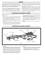
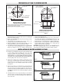
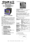
Chromalox
®
Installation, Operation
4
FXTH
and
PN401
RENEWAL PARTS IDENTIFICATION
161-051300-001
FEBRUARY, 2008
Chromalox Type FXTH Flexible Tank Heater
Vent Tube
Thermowell
Heater
Terminal
Housing
3/4” NPT
Bolts. See
Note 2
Heater Terminal Housing
9-3/16”
2”
Gasket (Furnished)
6-1/4”
2-1/2” NPT
Manhole Adapter (Optional)
Customer Manhole Cover
Thermowell
Lifting Cables
Riser
14’
Overtemperature
Sensor
12”
8”
Three Tube
Heater Assembly
Two Tube
Heater Assembly
Single Tube
Heater Assembly
B
C
Notes:
1. Min. fluid Depth for safe heater operation is 12”.
2. 5/8” - 11 x 1 in. long hex head bolts. 8 required.
Specifications – Type FXTH
Catalog Number of Recommended
OCC or WCC Control Centers
Amp / Tube
kW
240
480
Minimum
Manhole
Size (In.)
6
8
10
12
10
12
15
18
21
24
27
30
12
16
20
24
20
24
30
36
42
48
54
60
18
30
36
30
36
45
15
19
24
29
24
29
36
43
51
58
65
72
15
19
24
29
24
29
36
43
51
58
65
72
15
24
29
24
29
36
7
10
12
14
12
14
18
22
25
29
33
36
7
10
12
14
12
14
18
22
25
29
33
36
7
12
14
12
14
18
14
14
14
14
14
14
14
14
14
14
14
14
18
18
18
18
18
18
18
18
18
18
18
18
24
24
24
24
24
24
Heater
Length
B
Heater
Width
C
No. Tubes
and
Circuits
Catalog
Number*
Approx
Net Wt.
Lbs.
12’3-3/4”
15’3-3/4”
15’3-3/4”
15’3-3/4”
20’3-3/4”
20’3-3/4”
20’3-3/4”
27’1”
30’1”
32’1”
35’1”
40’1”
12’3-3/4”
15’3-3/4”
15’3-3/4”
15’3-3/4”
20’3-3/4”
20’3-3/4”
20’3-3/4”
27’1”
30’1”
32’1”
35’1”
40’1”
15’3-3/4”
15’3-3/4”
15’3-3/4”
20’3-3/4”
20’3-3/4”
20’3-3/4”
5-1/4
5-1/4
5-1/4
5-1/4
5-1/4
5-1/4
5-1/4
5-1/4
5-1/4
5-1/4
5-1/4
5-1/4
10-1/4
10-1/4
10-1/4
10-1/4
10-1/4
10-1/4
10-1/4
10-1/4
10-1/4
10-1/4
10-1/4
10-1/4
15-1/4
15-1/4
15-1/4
15-1/4
15-1/4
15-1/4
1
1
1
1
1
1
1
1
1
1
1
1
2
2
2
2
2
2
2
2
2
2
2
2
3
3
3
3
3
3
FXTH-11206
FXTH-11508
FXTH-11510
FXTH-11512
FXTH-12010
FXTH-12012
FXTH-12015
FXTH-12718
FXTH-13021
FXTH-13224
FXTH-13527
FXTH-14030
FXTH-21212
FXTH-21516
FXTH-21520
FXTH-21524
FXTH-22020
FXTH-22024
FXTH-22030
FXTH-22736
FXTH-23042
FXTH-23248
FXTH-23554
FXTH-24060
FXTH-31218
FXTH-31530
FXTH-31536
FXTH-32030
FXTH-32036
FXTH-32045
79
97
97
97
127
127
127
170
190
205
225
250
157
194
194
194
253
253
253
340
380
405
440
500
236
291
291
370
370
370
240V
(OCC or WCC)-15-213
WCC-25-213
WCC-25-213
WCC-30-213
WCC-25-213
WCC-30-213
WCC-40-213
WCC-45-213
WCC-55-213
WCC-60-213
WCC-70-213
WCC-75-213
WCC-15-223
WCC-25-223
WCC-25-223
WCC-30-223
WCC-25-223
WCC-30-223
WCC-40-223
WCC-45-223
WCC-55-223
WCC-60-223
WCC-70-223
WCC-75-223
WCC-15-233
WCC-25-233
WCC-30-233
WCC-25-233
WCC-30-233
WCC-40-233
*Suffix letters with FXTH Catalog Number indicate modification from standard as follows:
V= Voltage, W= Wattage, A= change in riser length, R= low temperature alarm contactor, D= temperature indicator and XX = special.
© 2010 Chromalox, Inc.
480V
WCC-10-413
WCC-10-413
WCC-15-413
WCC-15-413
WCC-15-413
WCC-15-413
WCC-20-413
WCC-25-413
WCC-30-413
WCC-30-413
WCC-35-413
WCC-40-413
WCC-10-423
WCC-10-423
WCC-15-423
WCC-15-423
WCC-15-423
WCC-15-423
WCC-20-423
WCC-25-423
WCC-30-423
WCC-30-423
WCC-35-423
WCC-40-423
WCC-10-433
WCC-15-433
WCC-15-433
WCC-15-433
WCC-15-433
(OCC or WCC)-20-433
GENERAL
The Chromalox FXTH Flexible Tank Heater is designed for heating viscous liquids in large steel, concrete or fibrous glass tanks with
normal manhole entry. Standard equipment with every heater
includes flexible pipe and 14’ riser(s), two lifting cables, 4” high
sludge legs and a 50-250° non-indicating thermostat with well,
overtemperature probe and weatherproof terminal housing.
vertical wall mounted brackets and hasp and staple for padlocking.
Electrical components include: Failsafe overheat device, master circuit-breaker, contactor(s), relay(s), selector switch, pilot lights, fuses
and a 120-volt control circuit transformer.
IMPORTANT-Before attempting to uncrate or install the FXTH
heater, read and understand all of the following instructions. Proper
handling is absolutely necessary to obtain satisfactory operation. All
electrical connections are to be made by a qualified electrician. To
avoid excessive separation, stratification, sludge formation, etc., in
your FXTH heated storage tank, consult a qualified oil supplier
regarding selection and blending of fuel oils.
The Control Center OCC (NEMA XII, oil and dust-tight construction) or WCC (NEMA IV, weather-resistant construction) is
designed for controlling the temperature of the viscous liquids by regulating the FXTH's on-off cycle. It is mounted remotely with standard
components consisting of a NEMA XII or NEMA IV enclosure with
UNCRATING AND HANDLING OF HEATER
NOTE: Inspect shipping crates before opening. Contact the carrier if
damage is evident.
4. Use several people to lift heater - the number depends on the
length and weight of the heater. As a guide, four men should be
used to lift and handle a dual tube 20 ft. unit.
5. Do not put any stress on the flexible riser tubes. These are not
designed for supporting weight. The unit must be lifted by either
the 3" heater tubes or the steel lifting cables furnished with heater
and located at both ends of heater. See Figure A.
6. Set heater in upright position on flat surface. Avoid any lateral
bending.
CAUTION: Never drop heater or subject it to mechanical shock.
1. Check to see that all components are included. FXTH immersion
heaters are shipped as subassemblies consisting of (a) flexible
heater with riser tubes, (b) terminal housing, (c) thermowells and
vent tube, and (d) control unit (if ordered).
2. To unpack flexible heater, keep crate in upright and horizontal
position when removing heater. Only top boards of crate need to
be removed.
3. When lifting heater assembly, do not bend heater to radius less
than 22". Heaters should be flexed in vertical plane only. This is
a plane perpendicular to the sludge leg base plates. Bending in
horizontal plane can damage internal ceramic insulators.
PRE·INSTALLATION CHECK OF HEATER
Rear Lifting Cable
Overtemperature
Probes
Heater
Back End
Front Lifting Cable
Heater Front End
Flexible
Risers
Sludge Leg Base Plates
Riser Unions
Terminal Housing
Figure A
1. Mechanical
The heater assembly has undergone a rigorous leak test just prior
to shipment from the factory. Visually inspect all joints and flex
tube surfaces to insure no mechanical damage has incurred during
shipping. Contact carrier if heater shows signs of damage. Do not
attempt to install heater if damage is evident. Do not attempt to
tighten or remove any of the threaded fittings in the flexible tube
assembly. If the sealing performed at the factory has been broken.
the unit must undergo another complete leak test supervised by an
Authorized Chromalox Serviceman before installing in tank.
2. Electrical
A. Open control unit cover and examine electrical components
for any damage which may have been incurred during shipment. Contact carrier and report any damage noted.
B. CAUTION: Retighten all electrical connections and mounted
components which may have loosened during shipment.
2
PREPARATION OF TANK TO RECEIVE HEATER
9-1/2” ± 1/4” Dia. Hole
By Customer
13” Dia.
(See Note 1)
By Customer
8 - 3/8” - 11 Drilled and
Tapped Equally Spaced
Holes on 11-3/4” B.C.
Manhole Cover Adapter Assy.
9-1/2” ± 1/4” Dia. Hole
By Customer
22-1/2”
Conduit
Opening
8 - 3/8” - 11 Drilled and
Tapped Equally Spaced
Holes on 11-3/4” B.C.
Manhole Cover
3/8” Min.
13-1/2” O.D.
3/4”
By Customer
Machining of Manhole Cover to Receive
FXTH Immersion Heater Terminal Box
1/4”
8”
Manhole Cover
1. Surface on top side of Tank Cover must be suitable for good gasket seating. The 13"
dia. area containing the gasket seat must be free of loose scale and rust and shall have
a maximum surface roughness of 250 RMS.
2. Bolt hole orientation to axis of storage tank is not important.
9-1/4” ± 14” By Customer
Machining of Manhole Cover to Receive
FXTH Immersion Heater Adapter Assembly
1. This Dimension is for Storage Tank Clearance Hole.
Figure B
Figure C
1. Double check internal dimensions of tank to be sure heater legs
will stand straight on portion of tank bottom to its full length
when in its operating position.
2. Remove any obstructions which may interfere with proper installation of heater into tank.
3. Clean manhole area to eliminate dirt and water which can be
picked up by heater during its insertion into tank.
4. Time the installation so oil level in tank is half full or less. This
will greatly facilitate insertion and positioning of heater.
5. Check sludge in bottom of tank to ensure it does not interfere with
operation of heater. Standard FXTH heaters are supplied with 4”
sludge legs. Sludge in excess of 3” must be removed before
installing heater. Sludge must not touch the corrugated heating
surface of the immersion unit.
6. Check point of tank suction to make sure it is 12” or more off bottom of tank. This will insure a minimum liquid level of 12” and
prevent heater from being uncovered while in operation. The
heater must not be energized unless it is completely submerged.
7. Machine manhole cover per Figure B or install optional terminal
housing manhole adapter to manhole cover or storage tank per
Figure C. All welds must be liquid tight.
DANGER: Hazard of Fire. If adapter is to be welded directly into
tank, remove flammable liquids, and vent all combustible gases or
vapors from storage tank before performing welding operations.
INSTALLATION OF HEATER ASSEMBLY IN TANK
1. If tank is type with manhole located near end of tank rather than
in center, install a temporary pulling cable at far end of tank
through any available port such as (l) fill pipe, (2) suction port, (3)
auxiliary manhole, etc., and thread the cable through the tank and
out the manhole to be used for installing the heater. The pulling
cable will be used to pull front lifting cable through auxiliary port
and then pulling cable is disconnected. See Figure D.
Figure D
2. Align heater assembly along centerline of tank having rear end
(riser end) of assembly farthest from manhole. Note: On tanks
with manhole near end rather than in center heater assembly
should be placed on side of manhole farthest from end of tank.
See Figure E.
3. Tie the riser(s) with rope or suitable line at a point just below the
union on riser(s). Anchor rope to any convenient nearby anchoring point. Length of rope should be sufficient to allow riser(s) to
be inserted into tank just inside manhole but not below oil level.
CAUTION: If oil gets into riser, it will cause failure of the heating element.
Figure E
4. Carefully turn heater over, feet upward, taking care it is flexed in
only the one plane. (See Figure F.) Support must be maintained on
riser end of heater to avoid overstressing riser(s) until heater is
lowered into tank.
Figure F
3
INSTALLATION OF HEATER ASSEMBLY IN TANK (cont’d.)
5. Begin lowering heater into tank as per Figure G, Step 1 thru 3
(end manhole) or Figure H, Step 4 thru 7 (center manhole). Once
the heater has touched bottom, use pulling wire (front lifting
cable) to pull heater toward far end of tank.
6. Before lowering back end of heater, visually gage the remaining
length of heater to be laid down, to be certain an equal amount of
clearance is allowed at both ends of tank. Back end of heater is
lowered into place using rear lifting cable. CAUTION: NEVER
USE RISERS TO SUPPORT HEATER TUBES.
7. Where additional heater assemblies are to be installed in the same
manhole, follow same procedure, being careful not to interfere
with risers or cable on the initial heater.
NOTE: In tanks where the configuration does not allow following
the above procedure, or in above ground tanks, ask for Factory recommendations for installation of heater.
Step 4
Step 1
Step 5
Step 2
Step 6
Step 3
Step 7
Figure G – Tanks with Manholes Near End
Figure H – Tanks with Center Manhole
INSTALLATION OF FXTH TERMINAL HOUSING
A. Position manhole cover adjacent to manhole. Very carefully untie
rope from anchoring point and pass it through (1) manhole gasket,
(2) opening in manhole cover, and (3) terminal housing gasket.
Securely refasten rope to anchoring point. Do not allow riser
end(s) to fall into oil, or permanent damage will result to the
heater. Bolt down manhole cover using a suitable gasket sealant if
required to obtain water-tight seal.
B. Pull riser(s) upward into position next to terminal housing. Wrap
teflon tape on threaded riser connections and fasten into underside
of terminal housing. Unused connections on bottom of housing
will already contain flush plugs. Attach lifting cables to ring on
under side of terminal housing.
C. Bolt terminal housing to manhole cover or manhole cover
adapter, again using suitable gasket cement. If manhole cover is
machined per Figure B, be sure to install copper gasket washers
under bolt heads. Position housing so conduit connections are in
the most convenient position for your particular installation.
Connect all riser leads to terminals, following markers on wires
and terminals referring to wiring diagram Figure J.
D. Install power leads from terminal housing to control center. See
Specifications Table, Page I for amperages to determine wire and
conduit size as determined by the National Electric Code.
E. To install thermostat wells, insert closed end of the well into brass
fitting in bottom of terminal housing. Push well completely to
bottom of tank. A preliminary measurement from manhole level
to tank bottom will aid proper insertion. The well may first hit the
heater. It is then necessary to manipulate the well so that it will
glance off the rounded heater surface and extend to tank bottom.
Mark side of tube at the swage fitting and then pun upward several feet to working level. Using a tube cutter, cut the tube at a
point exactly 7” below the mark. Once the tube is cut, be extremely careful the tube is not allowed to drop through fitting and into
tank. Partially tighten fitting so this cannot happen. Position the
upper end of well 5” off top of tube fitting, then firmly tighten the
fitting. Insert bushing (located in shipping bag inside of terminal
housing) into top of well. This will prevent burrs on tube from
cutting the bulb or capillary of thermostat. Repeat this procedure
until all wells are installed. There can be as many as three wells;
(1) Thermostat, (2) Temperature Indicator, (3) Low Limit Alarm.
F. Install thermostat mounting plate. Make sure thermowells are
aligned with openings in plate and over-temperature leads from
riser are brought through plate. Fasten plate into position.
4
INSTALLATION OF HEATER ASSEMBLY IN TANK (cont’d.)
G. Carefully unwind and straighten thermostat capillary tube. The
capillary must be reasonably straight. Be absolutely certain the
bulb is seated at bottom of well. Carefully coil any excess capillary and position next to thermostat and away from electrical connections. Repeat same procedure if low limit alarm is provided.
Attach wire for overtemperature sensor to terminals.
NOTE: Over-temperature control is located in the Chromalox
Control Center. If heater is supplied without control center, be
sure to obtain an over-temperature control for a positive thermistor, otherwise heater will be without over-temperature protection.
H. If the low temperature thermostat is being used, connect annunciator leads directly to terminals on this thermostat and provide an
independent power source. The switch rating is; 20 amp @ 115V,
15 amp @ 230V, pilot duty 125VA.
IL1
IL2
IL3
L1
L2
L3
Fuses 1
Terminal
Blocks
C1
AL1
F3
Circuit
Breaker
AL2
AL3
F4
F5
F6
2 C2
BL1
BL2
BL3
F7
F8
F9
3 C3
Ground
OCC & WCC Control Center
CL1
CL2
CL3
F10
F11
F1
F2
I. If temperature indicator is employed, wire in accordance with
Figure J. Use wire size as recommended for connecting to control
center.
J. Install control wiring through 3/4" conduit connection as indicated on page 1. Leave lid off' terminal housing until operational
check is completed. Install breather tube on the outside of the terminal box as shown on page 1, Make sure top of tube is at least
12" above the drainage water level. CAUTION: All conduit connections to terminal housing must be sealed to prevent entry of
any water, water vapor or condensation into terminal housing.
Breather tube length may be cut to shorten height, or extended for
higher flood levels by using 3/8” compression tube coupling and
3/8” tubing, as desired between formed breather tube and elbow
fitting on side of terminal housing.
H4 H2 H3
H1
H4
X2
Power On
G
H2 H3 H1 H4 H3 H2 H1
480V
240V
X1
ISS
Control Relay
1CR
Heat
Htr. Contactor #1
#1 Time Delay Relay(15 Sec.)
A
15
5
6
26
7
37
8
48
Overtemp. Terminal
Block
Control
5
6
7
8
Terminal
Block
1 TDR
2 TDR
#2 Time Delay Relay(30 Sec.)
Heat
Heater Contactor #2
Heat
Heater Contactor #3
Overtemp.
1CR
C1
Off - On
Control
4
Overtemp.
Probes
Non-Indicating
Temp. Control
A
1 TDR 2
Low Temp. Alarm
Contacts (Optional)
2 TDR 3
Temperature
Indicator (Optional)
C2
A
C3
R
1CR
A2
A1
Audible Alarm
(Optional)
NOTES: 1. Contactor “1 CON” and no fuses are supplied on single stage models.
2. Used on two stage models - fuses “3FU thru 8FU” - Contactor
“2 Con” - Time delay relay “1TDR” - Pilot light “3LT”.
3. Used on three stage models - fuses “3FU thru 11FU” - Contactor
“2 Con & 3 Con” - Time delay relay “1TDR & 2TDR” - Pilot
lights “3LT and 4LT”.
4. Termistor connections: Necessary Jumpers - Factory Wired
1 Heater
Thermistors located on heater with leads in conduit riser.
One thremistor per heater tube.
Figure J
5
2 Heaters
3 Heaters
ELECTRICAL AND OPERATIONAL CHECKS
A. Having circuit breaker and power switch in “off” position, make
sure proper voltage supplied matches voltage of control panel and
elements.
B. Adjust controlling thermostat in terminal housing to a 50°F reading. Increase setting until thermostat switch just “clicks”. This
setting is to be used for initial heater checkout.
C. Turn circuit breaker to “on” and note green power light coming
on. Turn on power switch and note first amber light will come on,
and then subsequent amber light(s) as explained in Section.
D. Observe control panel as heater goes through several heating
cycles. A cycle is determined when all amber lights are off. Cycle
interval can vary widely depending on amount of oil in tank.
However, the thermostat has been set to keep the cycle time to a
minimum.
E. Turn off circuit breaker and power switch, then re-set thermostat
to desired setting for normal operation. The thermostat contains a
factory adjusted stop which prevents settings above 150°F.
F. If low temperature alarm feature is provided, set this control 10°
to 15°F below the control thermostat setting.
G. Installation of terminal housing lid and gasket (with proper gasket
sealant) completes the check-out procedure.
H. If any difficulties are encountered during the installation and
check-out, call your local Chromalox Representative or
Chromalox Product Service.
INSTALLATION OF REMOTE CONTROL CENTER
CAUTION: Hazard of electric shock. Any installation involving
electric must be grounded to earth to eliminate shock hazard.
1. A safe maximum temperature limit on control cabinet components is 125°F. Choose a mounting location not in direct sunlight
or exposed to any other source of excessive heat. If the panel must
be mounted in direct sun, a sun shield must be employed.
2. Install proper control and power wiring to control center as per
Figure J. Power lines are to be sized for the particular heater load.
Double check to insure proper grounding procedures have been
followed for heaters and control panel.
3. Available inside control panel are connections A and A1 which
provide for an over-temperature alarm; such as, horn, bell, etc., to
be mounted remotely as required. These terminals are rated at
50VA, 120V.
4. Electrical
A. CAUTION: Hazard of severe shock. Make sure circuit
breaker and panel switch are in “off” position.
B. Make knockouts in control cabinet which are desired for final
wiring installation.
C. Connect leads from riser(s) to identified terminals shown on
Figure J.
D. TEMPORARY WIRING TO SIMULATE ACTIVATION OF
CONTROL CIRCUIT.
1. Jumper terminals S to S1.
2. Connect overtemperature control leads to terminals 5, 6, 7
or 8 as shown on Figure J.
3. Connect green ground wire lead from riser(s) to grounding
lug in control box and from control box to a suitable
ground.
4. Connect power cable of proper voltage to input of control
box.
5. Secure control box door, then place circuit breaker in “on”
position and energize heater with panel switch. Start with
45 second time interval and increase until a definite rise in
temperature on each heater tube can be felt with the bare
hand. NOTE: Adjustable time delay(s) in multi-stage units
have been preset at factory to provide steps for energizing
individual circuits.
6. Observe green light (which indicates “power”) when closing circuit breaker, first amber light with panel switch "on"
and subsequent amber light(s) (if any) at approximately 15
second intervals.
7. Have qualified electrician, using an amprobe, check amperage in individual heater leads to insure uniform amperage.
8. Turn circuit breaker to “off” position and remove temporary jumper from terminals Sand S1
Specifications – OCC and WCC Control Center (All Phases)
Catalog Number
OCC
WCC
Max.
No.
Max.
Amps Per
of
Dust and Oil Weatherproof
kW Volts Circuit Circuits Tight Models
Models
6
Dimensions
Inches
H
W
D
Approx.
Net Wt.
Lbs.
6
8
12
15
240
240
240
240
15
25
30
40
1
1
1
1
OCC-15-213
OCC-25-213
OCC-30-213
OCC-40-213
WCC-15-213
WCC-25-213
WCC-30-213
WCC-40-213
24
24
24
24
20
20
20
20
8
8
8
8
64
65
65
66
18
21
24
27
30
240
240
240
240
240
45
55
60
70
75
1
1
1
1
1
OCC-45-213
OCC-55-213
OCC-60-213
OCC-70-213
OCC-75-213
WCC-45-213
WCC-55-213
WCC-60-213
WCC-70-213
WCC-70-213
30
30
30
30
30
24
24
24
24
24
8
8
8
8
8
89
91
91
96
96
12
16
24
30
36
42
48
54
60
240
240
240
240
240
240
240
240
240
15
25
30
40
45
55
60
70
75
2
2
2
2
2
2
2
2
2
OCC-15-223
OCC-25-223
OCC-30-223
OCC-40-223
OCC-45-223
OCC-55-223
OCC-60-223
OCC-70-223
OCC-75-223
WCC-15-223
WCC-25-223
WCC-30-223
WCC-40-223
WCC-45-223
WCC-55-223
WCC-60-223
WCC-70-223
WCC-75-223
30
30
30
30
42
42
42
42
42
24
24
24
24
30
30
30
30
30
8
8
8
8
8
8
8
8
8
84
86
86
91
126
128
128
135
135
18
30
36
45
240
240
240
240
15
25
30
40
3
3
3
3
OCC15-233
OCC-25-233
OCC-30-233
OCC-40-233
WCC-15-233
WCC-25-233
WCC-30-233
WCC-40-233
36
36
36
36
30
30
30
30
8
8
8
8
113
120
125
127
6
8
15
18
21
27
30
480
480
480
480
480
480
480
10
15
20
25
30
35
40
1
1
1
1
1
1
1
OCC-10-413
OCC-15-413
OCC-20-413
OCC-25-413
OCC-30-413
OCC-35-413
OCC-40-413
WCC-10-413
WCC-15-413
WCC-20-413
WCC-25-413
WCC-30-413
WCC-30-413
WCC-30-413
24
24
24
24
24
24
24
20
20
20
20
20
20
20
8
8
8
8
8
8
8
64
64
64
64
64
64
64
12
20
30
36
42
54
60
480
480
480
480
480
480
480
10
15
20
25
30
35
40
2
2
2
2
2
2
2
OCC-10-423
OCC-15-423
OCC-20-423
OCC-25-423
OCC-30-423
OCC-35-423
OCC-40-423
WCC-10-423
WCC-15-423
WCC-20-423
WCC-25-423
WCC-30-423
WCC-35-423
WCC-40-423
30
30
30
30
30
30
30
24
24
24
24
24
24
24
8
8
8
8
8
8
8
84
84
84
89
91
91
96
18
36
45
480
480
480
10
15
20
3
3
3
OCC-10-433
OCC-15-433
OCC-20-433
WCC-10-433
WCC-15-433
WCC-20-433
36
36
36
30
30
30
8
8
8
113
113
113
OPTIONAL EQUIPMENT
Temperature Indicators (Suffix “D”)
(FXTH Heater Assembly and Control Center will have
suffix "D" e.g. FXTH-11206D, WCG15-213D)
It is very important the resistor wire be properly soldered after
adjusting.
MOUNTING
Temperature indicators are balanced for accurate reading in a normal
vertical position unless specified otherwise. All pyrometers labeled
"shielded meter" may be used in any type of panel with little or no
effect on calibration. Those labeled "non-magnetic" must be used
only on aluminum, plastic, wood or other non-magnetic panels. They
will read low if mounted in a steel panel. Pyrometers which are
labeled "magnetic" are intended for installation on steel panels. A
steel compensating ring is normally supplied where panel material is
not specified. Discard the ring when mounting on a steel panel. If the
pyrometer is used on a non-magnetic panel, the steel ring must be
used. Be sure the slit in the ring is at the top of the meter barrel and
the ring is pushed as far forward as it will go.
NOTE: When Thermocouples with external resistance higher than 10
ohms will be used, a special pyrometer will be required. The use of
other than thermocouple wire for leads or extensions may result in
improper ambient compensation.
ABBREVIATED TABLE OF THERMOCOUPLE RESISTANCE
The table lists the resistance in ohms per pair-foot for various types
of commonly used thermocouples for a number of different gauges of
wire. By using this table, it is necessary only to measure the length of
the thermocouple, knowing the type and gauge, to determine its
approximate resistance. (Actual measurement of the thermocouple
resistance is preferred to using the table.)
THERMOCOUPLE SELECTION AND CALIBRATION
Each pyrometer is marked on the dial with the type of thermocouple
and the total external resistance for which it is calibrated. Use of any
other type of thermocouple or one with a higher resistance than
marked will result in incorrect readings. (Type J thermocouples are
normally used.) All standard pyrometers are calibrated for 10 ohms
external thermocouple resistance and are provided with a 10 ohm calibrating resistor bobbin. (Non-standard pyrometers are usually calibrated for the specific external resistance ordered and no resistor bobbin is supplied.) This resistor bobbin must be adjusted so the total
resistance of the thermocouple and the bobbin add up to 10 ohms in
order to maintain calibration accuracy. Therefore, for a 5 foot, 20
gauge, iron-constantan thermocouple, the resistance of the thermocouple would be approximately 1.75 ohms and this resistance must be
subtracted from the calibrating bobbin. Each turn of the wire on the
resistor bobbin represents 0.5 ohms and for this example, 3-1/2 turns
would be removed. The total resistance of the thermocouple plus the
resistor bobbin would then add up to 10 ohms. For other values of
thermocouple resistance, simply remove more or less turns to adjust
for the total value of external resistance marked on the pyrometer
dial.
Gauge B & S
Ohms Per Pair - Foot
Iron/Constantan Copper/Constantan Chromel/Alumel
(Type J)
(Type T)
(Type K)
8
10
12
14
16
18
20
22
24
26
28
30
.0215
.0341
.0542
.0863
.1370
.2180
.3570
.5510
.8770
1.390
2:220
3.520
.0184
.0293
.0466
.0741
.1180
.1870
.2980
.4690
.7530
1.200
1.910
3.030
.0365
.0580
.0922
.1470
.2330
.3710
.5900
.9370
1.490
2.370
3.770
5.980
CHROMALOX TYPE TMC 7-DAY TIMER
TMC 7-day Calendar, Electric Dial Timer is used to provide automatic start-up/off-on control of large tank heaters or could be set up
for non-peak operation. Standard features: 7-day calendar dial permits different on/off schedules on different days of week. 2 to 14
replaceable trippers for up to 4 on/off operations per day, up to 28
on/off operations per week. 3 hour minimum on or off time; 21 hour
maximum on or off time. Independent 4-pole design allows SPST,
DPST, SPDT, switching. Manual on/off lever transfers switch operation without disturbing daily or weekly preset schedule. Heavy duty
synchronous motor suitable for operation between -40°F and +140°F.
Switch slider bar assures positive switching. Heavy duty terminals
accommodate up to AWG No.8 wire.
CAUTION: To set the correct day and time at beginning of initial
start-up, ROTATE THE PROGRAM CLOCK DIAL CLOCKWISE
ONLY. DO NOT ATTEMPT TO TURN POINTER!
Adjusting and Maintenance of Time Switch:
1. Periodically check trippers to insure that they are tightly fastened
to Program Clock dial. CAUTION: TIGHTEN TRIPPERS WITH
FINGERS ONLY!
2. Rotate Program Clock dial CLOCKWISE one hour in Spring to
adjust for daylight saving time (in areas where required). In Fall,
carefully rotate clock dial CLOCKWISE approximately one full
turn to reset at correct day and time for standard time. Check all
trippers to insure they have not moved during rotation.
3. The Program Clock motor is permanently lubricated. Lubrication
of other parts is not required.
4. The Program Clock switch contacts are factory set and need no
field adjustment.
OPERATION
“Off” Setting - de-energizes the entire zone control circuit, thus deenergizing all heating-cooling equipment in the zone. This setting can
be used for extended summer shutdowns, etc.
“Automatic” Setting - allows the Day-Night Clock Panel to cycle
the control system according to the program clock dial tripper settings.
To Set Trippers - Refer to picture for typical setup of a Seven Day
Program. Two trippers must be used for each day; an “A” tripper for
switching from “Night Setback” to “Day Operation” and a “B” tripper for switching from “Day Operation” to “Night Setback”.
7
Model
Renewal
Part No.
Operation
Volts
60 Hz
TMC71
311-057070-001
Seven Day
120
Switch
Amps
4 Pole
2 N.O.
2 N.C.
40
RENEWAL PARTS IDENTIFICATION
240
Catalog No.
Voltage
What the Catalog Number means:
FXTH – 2 12 12
WCC – 10 - 423
1 2 3 4
1
2 345
1 – Flexible Tank Heater
1 – OCC - Oil Tight & Dust Tight Control Center
2 – Number of Tubes
WCC - Weatherproof Control Center
3 – “B” Dimension
2 – Maximum Amperage per Circuit
4 – kW Rating
3 – Maximum Voltage 2 - 240, 4 - 480, 6 - 600
4 – Number of Circuits
5 – Phase
----------------------------------------------------------------------------------------------------------------------------------------Modified FXTH Standard Heater (FXTH-32036A)
Voltage................................................V
Wattage .........................................W
Change in Riser Length ......................................................................................A
Low Temp. Alarm Contacts ................................................................................R
Temperature Indicator.........................................................................................D
WCC
Voltage .............................................................................................................V
Audible Alarm .................................................................................................H
Time Clock.......................................................................................................T
Temperature Indicator .....................................................................................D
All Others .....................................................................................................XX
480
kW
Element Part Number
Element Part Number
FXTH-11206
FXTH-11508
FXTH-11510
FXTH-11512
6
8
10
12
063-115244-004
063-115244-003
063-115244-005
063-115244-009
063-115244-002
063-115244-004
063-115244-006
063-115244-010
FXTH-12010
FXTH-12012
FXTH-12015
FXTH-12718
FXTH-13021
FXTH-13224
FXTH-13527
FXTH-14030
10
12
15
18
21
24
24
30
063-115244-007
063-115244-011
063-115244-013
063-115244-015
063-115244-017
063-115244-019
063-115244-021
063-115244-023
063-115244-008
063-115244-012
063-115244-014
063-115244-016
063-115244-018
063-115244-020
063-115244-022
063-115244-024
FXTH-21212
FXTH-21516
FXTH-21520
FXTH-21524
FXTH-22020
FXTH-22024
FXTH-22030
FXTH-22736
FXTH-23042
FXTH-23248
FXTH-23554
FXTH-24060
12
16
20
24
20
24
30
36
42
48
54
60
063-115244-001 (2)
063-115244-003 (2)
063-115244-005 (2)
063-115244-009 (2)
063-155244-007 (2)
063-115244-011 (2)
063-115244-013 (2)
063-115244-015 (2)
063-115244-017 (2)
063-115244-019 (2)
063-115244-021 (2)
063-115244-023 (2)
063-115244-002 (2)
063-115244-004 (2)
063-115244-006 (2)
063-115244-010 (2)
063-115244-008 (2)
063-115244-012 (2)
063-115244-014 (2)
063-115244-016 (2)
063-115244-018 (2)
063-115244-020 (2)
063-115244-022 (2)
063-115244-024 (2)
FXTH-31218
FXTH-31530
FXTH-31536
FXTH-32030
FXTH-32036
FXTH-32045
18
30
36
30
36
45
063-115244-001 (3)
063-115244-005 (3)
063-115244-009 (3)
063-115244-007 (3)
063-115244-011 (3)
063-115244-013 (3)
063-115244-002 (3)
063-115244-006 (3)
063-115244-010 (3)
063-115244-008 (3)
063-115244-012 (3)
063-115244-014 (3)
Common Parts
Terminal Housing Manhole adapter ....................................
Manhole adapter Flange .....................................................
Manhole adapter Housing...................................................
Flange Gasket .....................................................................
Housing Gasket ..................................................................
Thermostat .........................................................................
Thermocouple Probe ..........................................................
Circuit Breaker Handle (150 Amps or less) ........................
Circuit Breaker Handle (151 Amps to 225 Amps)...............
Pilot Light - Red .................................................................
Amber ............................................................................
Green ............................................................................
Plexiglass Window .............................................................
Alarm .................................................................................
Selector Switch (WCC only) ...............................................
Selector Switch (OCC only) ................................................
Moto-gard Overtemp. Control ............................................
Control Relay 300V, 10A, 3 Pole.........................................
Time Clock - 7-day .............................................................
Pyrometer...........................................................................
NEMA - IV Seal on Circuit Breaker Handle .........................
Note: Number in ( ) indicates quantity of same part number used.
Part Number
306-115694-001
121-115692-001
065-115693-001
132-115515-001
132-113661-001
300-115621-001
309-121168-001
139-071820-000
139-071820-010
213-120816-005
213-120816-001
213-120816-002
207-121061-001
385-122101-001
292-120827-002
292-120827-001
300-115550-001
072-120451-001
311-057070-001
308-051161-001
139-071820-013
REPLACEMENT PARTS FOR OCC AND WCC CONTROL CENTER
Qty.
Description
Part Number
Qty.
OCC or WCC-10-413, 480V, 1-3ø, 6 & 8 kW
1
1
2
1
Circuit Breaker, 480V, 15 Amp, 3 pole........................104-071818-017
Contactor, 600V, 20 Amp, 3 pole................................072-120812-005
Fuses, 1/2 (F1 and F2) ...............................................128-114696-010
Transformer, 150VA....................................................315-048507-018
1
2
2
6
1
1
Circuit Breaker, 480V, 25 Amp, 3 pole........................104-071818-019
Contactors, 600V, 20 Amp, 3 pole..............................072-120812-005
Fuses, FNQ 6/10 (F1 and F2)......................................128-114696-005
Fuses, KTK-15 (F3 thru F8) ........................................128-047763-002
Transformer, 150VA....................................................315-048507-018
Time Delay Relay........................................................311-115540-001
1
3
9
1
2
2
Circuit Breaker, 480V, 30 Amp, 3 pole........................104-071818-020
Contactors, 600V, 20 Amp, 3 pole..............................072-120812-005
Fuses, KTK-15 (F3 thru F11) ......................................128-047763-002
Transformer 250VA ....................................................315-048507-024
Relay Time Delay........................................................311-115540-001
Fuse FNQ 6/10 (F1 and F2) ........................................128-114696-005
Description
Part Number
OCC or WCC-15-213, 240V, 1-3ø, 6 kW
1
1
2
1
Circuit Breaker, 240V, 20 Amp, 3 pole........................104-071818-003
Contactor, 600V, 20 Amp, 3 pole................................072-120812-005
Fuses, FNQ 8/10 (F1 and F2)......................................128-114696-011
Transformer, 150VA ...................................................315-048507-018
1
2
2
6
1
1
Circuit Breaker, 240V, 40 Amp, 3 pole........................104-071818-007
Contactors, 600V, 20 Amp, 3 pole ............................072-120812-005
Fuses, FNM8/10 (F1 and F2) .....................................128-114696-012
Fuses, KTK-20 (F3 thru F8) ........................................128-047763-002
Time Delay Relay........................................................311-115540-001
Transformer, 150VA....................................................315-048507-018
1
3
9
1
2
2
Circuit Breaker, 240V, 60 Amp, 3 pole........................104-071818-010
Contactors, 600V, 20 Amp, 3 pole..............................072-120812-005
Fuses, KTK-20 ............................................................128-047763-002
Transformer, 250VA ...................................................315-048507-024
Time Delay Relay........................................................311-115540-001
Fuse FNM 1- 4/10.......................................................128-114696-013
OCC or WCC-10-423, 480V, 2-3ø, 12 & 16 kW
OCC or WCC-15-223, 240V, 2-3ø, 12 kW
OCC or WCC-10-433, 480V, 3-3ø, 18 kW
OCC or WCC-15-233, 240V, 3-3ø, 18 kW
8
REPLACEMENT PARTS FOR OCC AND WCC CONTROL CENTER (cont’d.)
Qty.
Description
Part Number
1
1
2
1
OCC or WCC-15-413, 480V, 1-3ø, 10 & 12 kW
Circuit Breaker, 480V, 20 Amp, 3 pole........................104-071818-018
Contactor, 600V, 20 Amp, 3 pole................................072-120812-005
Fuses, FNQ 1/2 (F1 and F2)........................................128-114696-010
Transformer, 150VA....................................................315-048507-018
1
2
2
6
1
1
Circuit Breaker, 480V, 40 Amp, 3 pole........................104-071818-022
Contactors, 600V, 20 Amp, 3 pole..............................072-120812-005
Fuses, FNQ 6/10 (F1 and F2)......................................128-114696-005
Fuses, KTK-20 (F3 thru F8) ........................................128-047763-003
Transformer, 150VA....................................................315-048507-018
Time Delay Relay........................................................311-115540-001
1
3
9
1
2
2
OCC or WCC-10-433, 480V, 3-3ø, 30 kW
Circuit Breaker, 480V, 50 Amp, 3 pole........................104-071818-024
Contactors, 600V, 20 Amp, 3 pole ............................ 072-120812-005
Fuses, KTK-20 (F3 thru F11) ......................................128-047763-002
Transformer, 250VA....................................................315-048507-024
Time Delay Relay........................................................311-115540-001
Fuses, FNQ 6/10 (F1 and F2)......................................128-114696-005
1
3
9
1
2
2
OCC or WCC-15-433, 480V, 3-3ø, 36 kW
Circuit Breaker, 480V, 70 Amp, 3 pole........................104-071818-026
Contactors, 600V, 20 Amp, 3 pole..............................072-120812-005
Fuses, KTK-20 (F3 thru F11) ......................................128-047763-003
Transformer, 250VA....................................................315-048507-024
Time Delay Relay .......................................................311-115540-001
Fuses, FNQ 6/10 (F1 and F2)......................................128-114696-005
1
1
2
1
Circuit Breaker, 600V, 25 Amp, 3 pole........................104-071818-019
Contactor, 600V, 20 Amp, 3 pole................................072-120812-005
Fuses, FNQ V2 (F1 and F2).........................................128-114696-010
Transformer, 150VA....................................................315-048507-018
1
2
2
6
1
1
OCC or WCC-20-423, 480V, 2-3ø, 30 kW
Circuit Breaker, 480V, 50 Amp, 3 pole........................104-071818-024
Contactors, 600V, 20 Amp, 3 pole..............................072-120812-005
Fuses, FNQ 6/10 (F1 and F2)......................................128-114696-005
Fuses, KTK-25 (F3 thru F8) ........................................128-047763-004
Transformer, 150VA....................................................315-048507-018
Time Delay Relay .......................................................311-115540-001
1
3
9
1
2
2
Circuit Breaker, 480V, 70 Amp, 3 pole........................104-071818-026
Contactors, 600V, 20 Amp, 3 pole..............................072-120812-005
Fuses, KTK-25 (F3 thru F11) ......................................128-047763-004
Transformer, 250VA....................................................315-048507-024
Time Delay Relay .......................................................311-115540-001
Fuses, FNQ 6110 (F1 and F2).....................................128-114696-005
Qty.
OCC or WCC-25-233, 240V, 3-3ø, 30 kW
Circuit Breaker, 240V, 100 Amp, 3 pole......................104-071818-014
Contactors, 600V, 30 Amp, 3 pole ............................072-120812-005
Fuses, KTK-30 (F3 thru F11) ......................................128-047763-005
Transformer, 250VA....................................................315-048507-024
Time Delay Relay........................................................311-115540-001
Fuses, FNM 1- 4/10 (F1 and F2).................................128-114696-013
1
1
2
1
Circuit Breaker, 480V, 30 Amp, 3 pole........................104-071818-020
Contactor, 600V, 30 Amp, 3 pole................................072-120812-001
Fuses, FNQ V2 (F1 and F2).........................................128-114696-010
Transformer, 150VA....................................................315-048507-018
1
2
2
6
1
1
OCC or WCC-25-423, 480V, 2-3ø, 36 kW
Circuit Breaker, 480V, 60 Amp, 3 pole........................104-071818-025
Contactors, 600V, 30 Amp, 3 pole..............................072-120812-001
Fuses, FNQ 4/10 (F1 and F2)......................................128-114696-010
Fuses, FRS-35 (F3 thru F8) ........................................128-121133-063
Transformer, 150VA ...................................................315-048507-018
Time Delay Relay........................................................311-115540-001
1
1
2
1
OCC or WCC-30-213, 240V, 1-3ø, 12 kW
Circuit Breaker, 240V, 40 Amp, 3 pole .......................104-071818-007
Contactor, 600V, 30 Amp, 3 pole............................... 072-120812-005
Fuses, FNQ 8/10 (F1 and F2)......................................128-114696-011
Transformer, 150VA....................................................315-048507-018
1
2
2
6
1
1
Circuit Breaker, 240V, 80 Amp, 3 pole........................104-071818-012
Contactors, 600V, 30 Amp, 3 pole..............................072-120812-001
Fuses, FNM 8/10 (F1 and F2) .....................................128-114696-012
Fuses, FRN (F3 thru F8) .............................................128-121133-077
Time Delay Relay........................................................311-115540-001
Transformer, 150VA....................................................315-048507-018
1
3
9
1
2
2
OCC or WCC-30-233, 240V, 3-3ø, 36 kW
Circuit Breaker, 600V, 125 Amp, 3 pole......................104-071818-045
Contactor, 600V, 30 Amp, 3 pole................................072-120812-005
Fuses, FRN 40 (F3 thru F11) ......................................128-121133-077
Transformer, 250VA....................................................315-048507-024
Relays, Time Delay .....................................................311-115540-001
Fuses, FNM 1- 4/10 (F1 and F2).................................128-114696-013
1
1
2
Circuit Breaker, 480V, 40 Amp, 3 pole........................104-071818-022
Contactor, 600V, 30 Amp, 3 pole................................072-120812-001
Fuses, FNQ V2 (F1 and F2).........................................128-114696-010
OCC or WCC-25-413, 480V, 1-3ø, 18 kW
OCC or WCC-20-413, 480V, 1-3ø, 15 kW
OCC or WCC-30-223, 240V, 2-3ø, 24 kW
OCC or WCC-20-433, 480V, 3-3ø, 45 kW
OCC or WCC-30-413, 480V, 1-3ø, 21 & 24 kW
OCC or WCC-25-213, 240V, 1-3ø, 3 & 8 & 10 kW
Circuit Breaker, 240V, 30 Amp, 3 pole........................104-071818-005
Contactor, 600V, 30 Amp, 3 pole................................072-120812-005
Fuses, FNQ 8/10 (F1 and F2)......................................128-114696-011
Transformer, 150VA....................................................315-048507-018
1
2
2
6
1
1
Circuit Breaker, 240V, 70 Amp, 3 pole........................104-071818-011
Contactors, 600V, 30 Amp, 3 pole..............................072-120812-001
Fuses, FNM 8/10 (F1 and F2) .....................................128-114696-012
Fuses, KTK-30 (F3 thru F8) ....................................... 128-047763-005
Transformer, 150VA....................................................315-048507-018
Time Delay Relay........................................................311-115540-001
Part Number
1
3
9
1
2
2
OCC or WCC-15-423, 480V, 2-3ø, 20 & 24 kW
1
1
2
1
Description
OCC or WCC-30-423, 480V, 2-3ø, 42 kW
1
2
2
6
1
1
Circuit Breaker, 480V, 70 Amp, 3 pole .......................104-071818-026
Contactor, 600V, 30 Amp, 3 pole................................072-120812-001
Fuses, FNQ 4/10 (F1 and F2)......................................128-114696-010
Fuses, FRS-40 (F3 thru F8) ........................................128-121133-064
Transformer, 150VA....................................................315-048507-018
Time Delay Relay....................................................... 311-115540-001
1
2
2
6
1
1
Circuit Breaker, 480V, 80 Amp, 3 pole........................104-071818-027
Contactors, 600V, 30 Amp, 3 pole..............................072-120812-001
Fuses, FNQ 4/10 (F1 and F2)......................................128-114696-010
Fuses, FRS-45 (F3 thru F8) ........................................128-121133-065
Transformer, 150VA....................................................315-048507-018
Time Delay Relay........................................................311-115540-001
OCC or WCC-25-223, 240V, 2-3ø, 16 & 20 kW
OCC or WCC-30-423, 480V, 2-3ø, 48 kW
9
REPLACEMENT PARTS FOR OCC AND WCC CONTROL CENTER (cont’d.)
Qty.
Description
Part Number
1
1
2
1
OCC or WCC-35-413, 480V, 1-3ø, 27 kW
Circuit Breaker, 480V, 45 Amp, 3 pole........................104-071818-023
Contactor, 600V, 60 Amp, 3 pole................................072-120812-002
Fuses, FNQ V2 (F1 and F2).........................................128-114696-010
Transformer, 150VA....................................................315-048507-018
1
2
2
6
1
1
Qty.
Description
Part Number
1
1
2
1
OCC or WCC-55-213, 240V, 1-3ø, 21 kW
Circuit Breaker, 240V, 70 Amp, 3 pole........................104-071818-011
Contactor, 600V, 60 Amp, 3 pole................................072-120812-002
Fuses, FNQ 8/10 (F1 and F2)......................................128-114696-011
Transformer, 150VA....................................................315-048507-018
Circuit Breaker, 480V, 90 Amp, 3 pole .......................104-071818-028
Contactors, 600V, 60 Amp, 3 pole..............................072-120812-002
Fuses, FNQ 4/10 (F1 and F2)......................................128-114696-010
Fuses, FRS-50 (F3 thru F8) ........................................128-121133-066
Transformer, 150VA....................................................315-048507-018
Time Delay Relay........................................................311-115540-001
1
2
2
6
1
1
Circuit Breaker, 600V, 150 Amp, 3 pole .....................104-071818-046
Contactors, 600V, 60 Amp, 3 pole..............................072-120812-002
Fuses, FNM 8/10 (F1 and F2) .....................................128-114696-012
Fuses, FRN-70 (F3 thru F8) .......................................128-121133-081
Transformer, 150VA....................................................315-048507-018
Time Delay Relay .......................................................311-115540-001
1
1
2
1
OCC or WCC-40-213, 240V, 1-3ø, 15 kW
Circuit Breaker, 240V, 50 Amp, 3 pole........................104-071818-009
Contactor, 600V, 60 Amp, 3 pole............................... 072-120812-002
Fuses, FNQ 8/10 (F1 and F2)......................................128-114696-011
Transformer, 150VA....................................................315-048507-018
1
1
2
1
OCC or WCC-60-213, 240V, 1-3ø, 24 kW
Circuit Breaker, 240V, 80 Amp, 3 pole........................104-071818-012
Contactor, 600V, 60 Amp, 3 pole................................072-120812-002
Fuses, FNQ 8/10 (F1 and F2)......................................128-114696-011
Transformer, 150VA....................................................315-048507-018
1
2
2
6
1
1
OCC or WCC-40-223, 240V, 2-3ø, 30 kW
Circuit Breaker, 240V, 100 Amp, 3 pole......................104-071818-014
Contactors, 600V, 60 Amp, 3 pole..............................072-120812-002
Fuses, FNM 1- 4/10 (F1 and F2).................................128-114696-013
Fuses, FRN-45 (F3 thru F8)........................................128-121133-078
Time Delay Relay........................................................311-115540-001
Transformer, 250VA....................................................315-048507-024
1
2
2
6
1
1
OCC or WCC-60-223, 240V, 2-3ø, 48 kW
Circuit Breaker, 600V, 150 Amp, 3 pole......................104-071818-046
Contactors, 600V, 60 Amp, 3 pole..............................072-120812-002
Fuses, FNM 8/10 (F1 and F2) .....................................128-114696-012
Fuses, FRN-80 (F3 thru F8)........................................128-121133-082
Transformer, 150VA....................................................315-048507-018
Time Delay Relay........................................................311-115540-001
1
3
9
1
2
2
Circuit Breaker, 600V, 150 Amp, 3 pole .....................104-071818-046
Contactors, 600V, 60 Amp, 3 pole ........................... 072-120812-002
Fuses, FRN 45 (F3 thru F11) ......................................128-121133-078
Transformer, 250VA....................................................315-048507-024
Time Delay Relay .......................................................311-115540-001
Fuses, FNM 1-4/10 (F1 and F2)..................................128-114696-013
1
1
2
1
Circuit Breaker, 240V, 90 Amp, 3 pole........................104-071818-013
Contactor, 600V, 100 Amp, 3 pole..............................072-120812-003
Fuses, FNQ 8/10 (F1 and F2)......................................128-114696-011
Transformer, 150VA....................................................315-048507-018
1
1
2
1
OCC or WCC-40-413, 480V, 1-3ø, 30 kW
Circuit Breaker, 480V, 50 Amp, 3 pole........................104-071818-024
Contactor, 600V, 60 Amp, 3 pole................................072-120812-002
Fuses, FNQ 1/2 (F1 and F2)........................................128-114696-010
Transformer, 150VA....................................................315-048507-018
1
2
2
6
1
1
OCC or WCC-70-223, 240V, 2-3ø, 54 kW
Circuit Breaker, 600V, 175 Amp, 3 pole .....................104-071819-019
Contactors, 600V, 100 Amp, 3 pole ..........................072-120812-003
Fuses, FNM 1-1/8 (F1 and F2)....................................128-114696-020
Fuses, FRN-90 (F3 thru F8)........................................128-121133-083
Transformer, 250VA....................................................315-048507-024
Time Delay Relay........................................................311-115540-001
1
2
2
6
1
1
Circuit Breaker, 480V, 100 Amp, 3 pole......................104-071818-029
Contactors, 600V, 60 Amp, 3 pole..............................072-120812-002
Fuses, FNQ 4/10 (F1 and F2)......................................128-114696-010
Fuses, FRS-35 (F3 thru F8) ........................................128-121133-063
Transformer, 150VA....................................................315-048507-018
Time Delay Relay........................................................311-115540-001
1
1
2
1
Circuit Breaker, 240V, 100 Amp, 3 pole......................104-071818-014
Contactor, 600V, 100 Amp, 3 pole..............................072-120812-003
Fuses, FNQ 8/10 (F1 and F2)......................................128-114696-011
Transformer, 150VA....................................................315-048507-018
OCC or WCC-35-423, 480V, 2-3ø, 54 kW
OCC or WCC-55-223, 240V, 2-3ø, 42 kW
OCC or WCC-40-233, 240V, 3-3ø, 45 kW
OCC or WCC-70-213, 240V, 1-3ø, 27 kW
OCC or WCC-40-423, 480V, 2-3ø, 60 kW
OCC or WCC-75-213, 240V, 1-3ø, 30 kW
OCC or WCC-45-213, 240V, 1-3ø, 18 kW
1
1
2
1
Circuit Breaker, 240V, 60 Amp, 3 pole........................104-071818-010
Contactor, 600V, 60 Amp, 3 pole................................072-120812-002
Fuses, FNQ 8/10 (F1 and F2)......................................128-114696-011
Transformer, 150VA....................................................315-048507-018
1
2
2
6
1
1
Circuit Breaker, 600V, 125 Amp, 3 pole......................104-071818-045
Contactors, 600V, 60 Amp, 3 pole..............................072-120812-002
Fuses, FNM 8/10 (F1 and F2) .....................................128-114696-012
Fuses, FRN-60 (F3 and F8..........................................128-121133-080
Transformer, 150VA....................................................315-048507-018
Time Delay Relay........................................................311-115540-001
OCC or WCC-72-223, 240V, 2-3ø, 60 kW
1
2
2
6
1
1
OCC or WCC-45-223, 240V, 2-3ø, 36 kW
10
Circuit Breaker, 600V, 200 Amp, 3 pole......................104-071819-020
Contactors, 600V, 100 Amp, 3 pole .......................... 072-120812-003
Fuses, FNM 1-1/8 (F1 and F2)....................................128-114696-020
Fuses, FRN-100 (F3 thru F8) .....................................128-121133-084
Transformer, 250VA....................................................315-048507-024
Time Delay Relay........................................................311-115540-001
11
Limited Warranty:
Please refer to the Chromalox limited warranty applicable to this product at
http://www.chromalox.com/customer-service/policies/termsofsale.aspx.
1347 HEIL QUAKER BLVD., LAVERGNE, TN 37086
Phone: (615) 793-3900
www.chromalox.com