1
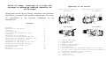
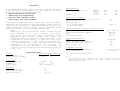
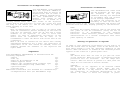
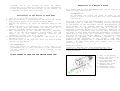
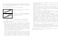
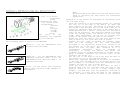
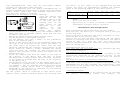
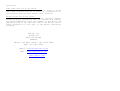
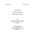
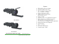
Features
• High quality, full screen image
• Internally lighted red reticle
• Shock resistant on large caliber
(inc. .375H&H, .416Rigby)
• Lighted, high-power optics
• Image protection from lateral
and dot light sources
• Long eye relief
• Maintains rifle’s zero at adjustment of focus
• Built-in high-power (75mW), hazard-free
IR illuminator with adjustable power
• Precision internal windage/elevation adjustment
• Camera/and camcorder/adaptable
• Various mount
• Water resistance
• Low power consumption
• Compact/Light weight
NVD-NORS210
NVD-NORS220
NIGHTVISION RIFLESCOPES
(Generation Super I+)
OPERATIONAL MANUAL
Rules of usage, mounting to a rifle and
storage to maximize feature benefits of
rifle scope
Infringement of the rules of storage, adaptation and utilization
of the device as stated in the operation manual may be a cause
for cancellation of the warranty obligations of the
manufacturer.
Contents
Features
Appearance of the device
Overview
Specifications
Utilization of 2x magnifier lens
Components
Installation of batteries
Testing of operation during daytime
Utilization of the device in dark time
Adaptation to a hunter’s rifle
Dimensions of the reticle
Adjustment of the scope on the rifle
Taking photos and video shooting
Maintenance and storage rules
Troubleshooting
Warranty
Acceptance certificate
Appearance of the Devices
With objective 64mmF/1.2
NVD-NORS210
6
5
2
1
2
3
3
4
4
4
4
5
5
8
8
8
9
9
10
10
7
3
11
1
4
With Objective 100mm/1:1.5
NVD-NORS220
6
2
5
7
11
1
NVD-NORS210
3
4
NVD-NORS220
12
8 9 10
8
9
10
1 - Body of the device
2 – Objective lens
3 – Eyepiece lens
4 - Rubber eyepiece guard
5 - Battery compartment
6 - IR illuminator
7 - Horizontal/Vertical adjustment handle of the reticle
8 - On /Off /power alteration switch of the IR illuminator
9 - Brightness adjustment of the reticle
10 - Objective focusing handle
11 - Rifle mount
12 - Objective cover
Overview
Your NVD-NORS210 Night Vision Scope is a modern, universal
night vision device designed for a wide range of activities
from professional to amateur activity:
• Night observation and hunting
• Patrolling and safeguarding
• Rescuing and searching works
• Night photo and video shooting.
The device is equipped with a First plus Generation highquality electronic-optical image intensifier (Gen. Super I+)
employing the principle of multiple intensification of the
image brightness in the visible and IR radiation which
guarantees an up to 150-350 m observation range.
NOTE.
Observation and identification range provided by the
device depends on the value of natural night light,
type of the objective lens used, transparency of the
atmosphere
and
contrast
between
the
target
and
background. The identification range increases in the
conditions of good lighting, at moonlight night given
outside illumination, if the target is situated on a
light background (sand, snow). The identification range
decreases in the conditions of weak lighting, low
transparency of the atmosphere, if the target is
situated on the dark background (plough-land, stems of
trees, etc.).
The mechanical
Overall dimensions, mm
Length
Width
Height
Weight, g
Electrical parameters
Power source – battery of the type AA
Feed Voltage, V
Battery Life, h
-in a passive mode
-in an active mode
Electronic-optical image intensifier tube
Type
Photocathode sensivity,µA/Lm
Gain
Resolution, Lp/mm
Infra-Red illuminator
Type
Power of light radiation, mW
Angle of radiation, degree
Wave length , nm
Conditions of work
Range of working temperatures
Relative humidity
240
80
78
790
270
100
78
870
2pc.
3
min. 60
5
Gen. Super I+
min.280
min.1000
min.45
IR diode
75
8-10
805
-40° up to +50°C
0 to 98%
Specifications
General
Magnification, x
Field of view, degree
NVD-NORS210 NVD-NORS220
1.6 (3.2*) 2.5
17 (9*)
11
Objective
Focal length, mm
F-number
Focus range
64 (128)
100
1:1.2
1:1.5
10m to infinity
Eyepiece
Focal length, mm
Eye Relief Distance
Diopter setting
16
45
+4, -4
(*) - with 2x magnifier lens.
P.S.
1. The screen may have separate black dots or small groups of
dots allowed by the technology of tubes’ production at the
manufacturing plants.
Utilization of 2x Magnifier Lens
Installation of Batteries
Your NVD-NORS210 (type equipped
with the objective 64mmF/1.2)
can be used with an optical 2x
magnification lens in order to
obtain doubled magnification.
The lens (identified as 2x)
doubles focal length of the
objective. It is fixed on a
setting thread under the light filter of the objective
(outer side of the objective). To take off a cover (12) from
the body of the device (1). The 2x lens must be tightly
fixed screwing it to the rest.
NOTES.
When 2x magnification lens is used in an active mode
(with IR illuminator) partial darkening of the field of
view will be observed, since the 2x lens has a large
diameter of the objective. In order to avoid this
effect (in case of simultaneous utilization of the
device with IR illuminator and 2x lens) it is
recommended to order the device with Z-like form of the
illuminator.
When a 2x lens is ordered for the device with already
implemented adaptation for a rifle, the opportunity of
installment of 2x lens should be checked, since its
diameter exceeds the diameter of the objective and
equals 80mm.
Components
Your NVD-NORS210 (NVD-NORS220) is delivered with the
following components:
-Device
1pc
-Lens cap
1pc
-Built-in IR illuminator 75 mW
1pc
-Rubber Eyepiece Guard
1pc
-Adaptor rail (Standard prism or Weaver type)
1pc
-Camera/video adapter ring (52mm/37mm)
2pc
-Operation manual
1pc
-Carrying Case
1pc.
Additional accessories (not included in a standard set):
-2x Magnification Lens (for NVD-NORS210 only)
Your NVD-NORS210/220 works from
two AA batteries. Be sure that
the
batteries
are
in
good
condition and they are installed
in accordance with the picture
on the battery compartment.
To replace the batteries it is
necessary to turn off the unit,
remove the cover of the battery compartment and replace old
batteries with new ones, keeping polarity of the batteries.
NOTE.
To ensure the longest operation time of the device and
full power of the IR illuminator (using one set of
batteries)
it
is
recommended
to
use
alkaline
batteries.
These batteries possess the most stable
characteristics of a current consumption when their
power capacity is reduced.
Testing of Operation in Daytime
In order to test operation of the device you can turn it on
with the closed cover in daytime. Cover of the device has a
hole small enough to test the operating condition of the
device. When the device is turned on the observed picture
appears on the screen in a yellow-green color.
NOTE.
The device won’t burn out even if you open the cover
of the objective. When the light is excessively bright
protection will be activated
and the image will
curtail. When the device is placed in a dark place the
image will be restored in several seconds.
CAUTION.
The device is not supposed to be directed toward
bright sources of light: bright lamps, the sun,
welding and etc – it may result in the reduction of
the coefficient of brightness magnification of the
device. In order to avoid the fatigue of photo-
cathode, it is not allowed to leave the device
motionless in a turned on condition in the excessively
bright environment (in the morning, in the evening, in
a daytime) for more than 30 minutes.
Utilization of the Device in Dark Time
1. Open the cover of the objective lens.
2. Turn on the device – position ON of the switch (8). Green
light should appear on the screen (passive mode).
3. Turning the eyepiece (3) reach the sharpest image of the
mark.
4. Choose the object of observation and focus the objective
of the device with the handle (10) until you see a
distinct and sharp image of the observed object.
5. When illumination of the observed object is required,
turn on (8) the IR illuminator (active mode). You can
select
one
of
the
three
positions
changing
the
illuminator’s power (10, 35 or 75 mW).
6. Having finished the work, turn the ON / OFF switch (8) to
the OFF position.
7. Close the cover of the objective after you have finished
the work of the device.
RECOMMENDATION.
When the device is stored for a long time it is
recommended not to leave batteries in the compartment
of the device in order to avoid leakage of the
batteries.
Adaptation to a Hunter’s Rifle
Your night vision scope NVD-NORS210/220 can be used as a
hunter’s night vision scope.
RECOMMENDATION.
We recommend you verify the order of usage of the
hunter’s scope on your rifle with the local competent
authorities.
Your night vision scope NVD-NORS210/220 can be used with
different types of mountings, providing reliable fixation
of the device on the particular rifles. Manufacturers of
civil rifles do not possess uniform standards for a
mounting place of optical devices, and as a result, a
universal fastening device is not available. Dedal-210 is
supplied with a fastening mount without hard fastening to
the body, in most cases allowing the performance of special
adaptation of the device for a particular model of rifles.
For this purpose you should address a specialized rifle
workshop or implement the fastening yourself, if you
possess enough knowledge of the system.
The NVDNORS210/220 are shipped with a standard Weaver mount rail
system.
If this works with your system, move to the
Variant II Section.
Adaptation rules.
Variant I – Adapter rail with Standard Prism type.
Fastening of the device is made with the help of the
following parts:
DO NOT FORGET TO TURN OFF THE DEVICE AFTER USE!
1- body of the device
2- front feet with of the
Standard prism
3- rear feet with the
Standard prism
4- adaptor rail with
Standard prism
5- fastening screws
6- transverse screws.
The front and rear feet (2,3) with
transverse screws (6)
are standard feet with standard prism (4). They are produced
by the companies manufacturing scopes mounts (for example,
Ernst Apel Gmbh, Germany)).
-
The following types of rails are recommended:
SP200-64 - for the device NVD-NORS210
with objective 64mm,
SP200-100 - for the device NVD-NORS220
with objective 100mm or NVD-NORS210 +
2x Magnification Lens.
NOTE.
The rails SP200-64, SP200-100 move the device back.
This is necessary for some rifles for comfortable
use.
Adaptation of the device is performed in consistency with
the following rules:
- Check the elevation of the fastening screws (5), pulling
the rail (4) to the body of the device (1) above the
upper surface of the rail. The height of elevation must
not exceed 3.0mm and must not be less than 2.5mm. It is
especially important when the body of the device has a
blind aperture with a thread (front hole for the device
with a 64mm objective). The elevation should not exceed
3.5mm for through holes and should not be less than
2.5mm. This requirement can be met by cutting axle length
of the screws from the side of the thread;
- Screw off screws (6) from feets (2,3);
- Fix the feets (2,3) to the rail (4). Fasten the feets
(2,3) to the rifle. Moving the rail in the feets find
such a position of the device when your eye reaches the
edge of the Eyepiece Guard or in case of a large caliber
(for example, .375 H&H Mag) your eye should be situated
at the distance of 2-5cm from the edge of the rubber
eyepiece Guard. The device should be located in the
-
-
-
position which allows comfortable observation without
stretching forward;
Screw the screws (6) in supports (2,3) from the opposite
side to fix the selected position of supports (2,3) at
the rail (4);
Drill the rail(4)at the place of disposition of
screws(6) using supports (2,3)as conductor. Control the
depth of drilling not to damage screws (it is desirable
to use a special accommodation of the firm Ernst Apel
(Ref.22000));
Cut an excessive part of the rail (4);
Screw off screws(6) and twirl them in regular position
into perforated holes through supports (2,3). Fasten
screws (6) with the fixed composition;
Remove fat from the surface (A)of the rail and from the
body of device at the place that will be glued;
Prepare the glue (glue is needed, for example, epoxy
with the tear strength not less than 200kg/cm2)
according to its preparation instruction, and put it on
the surface (A) of the rail. The surface of the screws
should not have any glue. This condition is of a
considerable
importance,
since
it
provides
an
opportunity to repair the device and remove the
alignment rail for further adaptation to another rifle;
Apply a hermetic substance (of silicone type) on the
thread of the screws (5). It is necessary to exclude the
hit of moist air into the device and to avoid sweat of
it;
Fix the rail (4) to the body of the scope with the help
of the screws (5) cut at the required length;
Remove glue surpluses appeared in the place of alignment
of the plate with the body with a dry napkin and let the
glue solidify in accordance with its instruction (for
example, 24 hours in case of epoxy glue).
Adaptation has been completed and the device is ready for
use as a hunter’s scope.
Variant II – Adapter rail with 7/8’’ Weaver prism type.
Fastening of the device is made with the help of the
following parts:
1-body of the device
2-fastening
screws
3-adapter rail with
7/8’’ Weaver prism
encompassing:
4-insert
rest
5-insert
6-clamp
7-clamp
screw.
All
parts
of
the
alignment are supplied
by JSC Dedal-NV.
The following types of rails are recommended:
WP135-64 - for the NVD-NORS210 with
standard objective 64mm,
WP150-100 - for the NVD-NORS220 with
standard objective 100mm or for the
NVD-NORS210 with objective 64mm + 2x
Magnification Lens.
WP90-64 - for the device with objective
64mm or with objective 100mm (NORS210 or
NVD-NORS220).
NOTE.
The mounts WP135-64, WP150-100 move the device back,
which is necessary for some rifles for comfortable
supervision.
Adaptation of the device is performed in consistency with
the following rules:
- Check the elevation of the fastening screws (2), pulling
the rail (3) to the body of the device (1) above the
upper surface of the rail. The height of elevation must
not exceed 3.0mm and must not be less than 2.5mm. It is
especially important when the body of the device has a
blind aperture with a thread (front hole for the device
with a 64 mm objective). The elevation should not exceed
3.5mm for through holes and should not be less than
2.5mm. This requirement can be met by cutting axle
length of the screws from the side of the thread;
- Remove fat from the surface (A)of the rail and from the
body of device at the place that will be glued;
- Prepare the glue (glue is needed, for example, epoxy
with the tear strength not less than 200kg/cm2)
according to its preparation instruction, and put it on
the surface (A) of the plate. The surface of the screws
should not have any glue. This condition is of a
considerable
importance,
since
it
provides
an
opportunity to repair the device and remove the
alignment plate for further adaptation to another rifle;
- Apply a hermetic substance (of silicone type) on the
thread of the screws (2);
- Fix the rail to the body of the scope with the help of
the screws (2) cut at the required length;
- Remove glue surpluses appeared in the place of alignment
of the rail with the body with a dry napkin and let the
glue solidify in accordance with its instruction (for
example, 24 hours in case of epoxy glue);
- Place the scope on the rail of the rifle in such a
position when your eye coincides with the edge of the
Eyepiece Guard or in case of a large caliber (for
example, .375 H&H Mag) your eye should be situated at
the distance of 2-5cm from the edge of the Eyepiece
Guard. The device should be located in the position
-
-
which allows comfortable observation without stretching
forward;
Place inserts (4,5) in the apertures of the rail (3). The
insert (4) is placed with a projection (B) looking
downwards in the nearest slot on the rail of the rifle.
If there is no such a slot, the insert
(4) is placed
with a projection (B) looking upwards. It is recommended
to place the inserts at the maximum possible distance
from each other;
Place clamps (6) and clamp screws (7) in the inserts
(4,5). Tighten screws (6,7) in order to obtain hard
fixation. When necessary the excessive front part of the
rail (3) can be removed.
Adaptation has been completed and the device is ready for
use as a hunter’s scope.
Dimensions of the Reticle
Type of the reticle is
presented at the drawing.
Brightness of reticle can
be regulated with toggle
switch (9). Dimensions are
given in meters for the
distance
100m
for
the
objective
64mm
(NVDNORS210)
Dimensions
in
brackets are given for the
objective
100mm
(NVDNORS220)
Adjustment of the scope can be performed in daytime with
the closed cover of the objective or in the twilight on the
adjusted target or on the remote point.
Adjustment of the scope is performed in the following way:
- Fix the scope on the fit of the rifle;
- Set a panel with a target or select the point of aiming;
- Set the rifle on the scoped machine;
- Direct the rifle to the point of aiming by mechanical
sight (bead with a slot) (if it is possible). At this
stage it is suitable to apply laser of cold test
shooting (LCTS) inserted in the barrel of the rifle,
which
indicates
geometrical
point
of
the
barrel
position.
- Unscrew the protective caps of the bias screws of the
aimed graticule. Turning the bias screws of the reticle
obtain the matching of reticle crosshairs with the aimed
point, set by the mechanical sight or LCTS;
- Remove the rifle from scoped machine and take out LCTS;
- Make 2-3 shots. Having examined the target make
necessary corrections (for example, in order to move the
hit point downwards and leftwards, screws of the
mechanism should be turned counter clockwise, in the
directions Down and Left correspondingly. The aiming
point is moving upwards and rightwards);
- Make a control shot and find out whether the aiming
point coincides with the bullet hit point. (Make the
correction again if necessary);
- Set the protective caps into their places.
The device is ready for operation.
Performing the adjustment it should be taken into
consideration that the displacement mechanism of the
reticle of the device is equipped with a clicking fixer
providing the following presented characteristics:
Focal length of objective lens
64mm
100mm
Displacement of the reticle at the
turn of the screw for one click at
a distance of 100m
30mm
19mm
Adjustment of the Scope on the Rifle
Before the adjustment of the scope, objective lens should be
adjusted for a distant object (select infinity) in a dark
time with the opened cover of the objective.
Taking Photos and Video Shooting
Your NVD-NORS210/220 comes with the photo/video adapter
allowing for night photo/video shooting.
Night photo shooting with the device NVD-NORS210/220 is
easily performed with application of mirror 35mm SLR cameras
(Nikon, Canon, Pentax etc) with standard objectives that
have the focal length of 50-58 mm.
Preparation of the device for photo shooting:
- Screw the adapter ring
supplied
in
the
set
(diameter 52mm or 37mm)
to the rest into the
setting place of the
light
filter
of
the
objective
in
your
camera.
(If
the
objective
of
your
camera
has
another
setting diameter for a light filter (for example, 49mm or
58mm) your have to purchase adapter rings from the size
of 52mm to your size);
- Remove the rubber eyepiece guard from the scope;
- Set the eyepiece in the medium position;
- Fix the adapter ring with a camera on the cylindrical
belt of the eyepiece body;
- Switch on the device and focus the assembled system with
the help of the objectives of the device and camera. If
the image cannot be focused the camera with the ring
should be removed and the coupling of the eyepiece of the
device should be turned a little. Assemble the system
again and check its focusing. At some position of the
eyepiece and objective of the camera the system will be
focused exactly;
- Fasten the adapter ring with the camera to the body of
the eyepiece of the device with the help of three
blocking screws. During further photo shooting sharpness
of the system is obtained with the help of the objective
of the device only;
- Set diaphragm on the objective of the camera equal 2.8 or
4 (shooting is possible even at lower diaphragm indices,
for example 2, but the obtained pictures will have worse
resolution). Taking photos with a completely opened
diaphragm of the objective is justified for the shooting
of quickly moving objects only.
The TTL system, which is installed at most mirror prism
cameras easily estimate exposure during the shooting with
the device. If your camera is not equipped with the TTL
system, the table can approximately estimate the shutter
speed at the diaphragm number of the camera equal 2.0:
ISO
50 100
200
Shutter speed, sec.
1
1/4
1/2
400
1/8
800
1600
1/15
1/30
3200
1/60
NOTES.
Use a film ISO 400 or more.
Application of a tripod is strongly recommended for
achievement of higher quality of photos.
VIDEO
Maintenance and Storage Rules
Device maintenance and storage rules are very simple:
Keep and carry the device in a closed box with a cover put
on the objective.
Protect the device from hits and direct influence of rain,
snow and dust on the optical parts.
Protect the box from moisture penetration and the device
should be protected from direct sun influence. The device
should be kept in a warm dry place far from heating
devices. Batteries should be taken out. Storage temperature
must not exceed 60°C.
NVD-NORS210/220 does not work . . .
Make sure that the batteries have been installed and they
are in good condition.
NVD-NORS210/220 cannot be focused . . .
Adjust the objective lens and eyepiece according to the
instructions specified in the Operation section. If the
device is not still focusing wipe and clean the optical
parts.
The image has faded or disappeared completely . . .
Bright source of light can be a reason of the image
reduction, loss of resolution or complete disappearance. If
NVD-NORS210/220 has been switched off automatically, turn
the switch to the position OFF. The unit will be ready for
use in one-two seconds.
Condensation effect . . .
In order to avoid misting of the eyepiece lens in cold time
use
special
anti-damping
covers
(for
example,
for
spectacles).
Some black dots are on the screen . . .
The image may contain small black dots or groups of black
dots. Most of black dots can be seen only in daytime and in
the operation mode the dots become almost invisible.
Bright points are on the screen . . .
The image may contain some bright points caused by gradual
relief of static electricity from the cathode. This feature
may appear immediately after the assembly of the device and
removal/setting of the objective from/to the device, and it
always disappears in 5-14 days of the device utilization
(storage).
Koflar I/S
Toften 40
9280 Storvorde
Denmark
Phone: +45 9831 0496 / +45 2976 0499
Fax: +45 9831 0497
Email: [email protected]
web : www.nightvision.dk
www.redliv.com