1
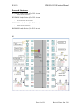
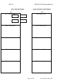
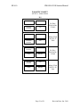
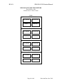
EE 410 Winter 2009 Prof. Krishna Saraswat CMOS-LOCOS CMOS Process for EE410 INSTRUCTION MANUAL Prepared by Hyun-Yong Yu, Yeul Na, Li-Wen Chang, Jin-Hong Park, Jae Hyung Lee, J. Jason Lin and Dr. Edward Myers Electrical Engineering Dept. Center for Integrated Systems (CIS) and The Stanford Nanofabrication Facility (SNF) Stanford University EE 410 CMOS LOCOS Student Manual TABLE OF CONTENTS 1 2 INTRODUCTION ...................................................................................................... 3 LABORATORY SAFETY ......................................................................................... 3 2.1 Safety Philosophy ............................................................................................... 3 2.2 General Safety..................................................................................................... 4 3 BACKGROUND ........................................................................................................ 5 4 SUMMARY OF CMOS-LOCOS ............................................................................... 6 4.1 General Features ................................................................................................. 6 4.2 Comparison to Typical CMOS Processes........................................................... 7 4.3 Modifications from CIS/CMOS to CIS/CMOS-II.............................................. 7 4.4 Modifications from CIS/CMOS-II to CMOS-LOCOS....................................... 7 5 PHOTOLITHOGRAPHY........................................................................................... 8 5.1 Description of Mask Levels ................................................................................ 8 5.2 Mask Alignment Patterns.................................................................................... 9 5.3 Mask Alignment Errors ...................................................................................... 9 5.4 Lithography Procedures .................................................................................... 10 6 PROCESSING TECHNIQUES ................................................................................ 10 6.1 Laboratory Safety.............................................................................................. 10 6.2 Clean-Room Techniques................................................................................... 10 6.3 Wafer Cleaning Techniques.............................................................................. 11 7 PROCESS FLOW..................................................................................................... 11 7.1 Global Alignment Marks and Blanket Substrate-Implantation ........................ 11 7.2 Field Oxidation and Active Region Definition................................................. 12 7.3 P-Well Formation and Kooi Oxidation............................................................. 12 7.4 Gate Oxidation .................................................................................................. 13 7.5 Polysilicon Gate Formation .............................................................................. 13 7.6 Source/Drain Implantations .............................................................................. 14 7.7 Low Temperature Glass (LTO) Deposition...................................................... 14 7.8 LTO Densification and Silicon Anneal............................................................. 14 7.9 Contact Hole Formation and Metallization....................................................... 14 7.10 Final Passivation for Packaging (Optional) ..................................................... 15 8 SIMULATIONS ....................................................................................................... 17 8.1 Process Simulations .......................................................................................... 18 8.2 Device Simulations ........................................................................................... 19 8.3 Circuit Simulations (Optional).......................................................................... 19 9 TEST STRUCTURES AND MEASUREMENT METHODOLOGY ..................... 19 9.1 Fabrication Test Structures ............................................................................... 20 9.2 Process Test Structures ..................................................................................... 20 9.3 Device Test Structures ...................................................................................... 23 9.4 Circuit Test Structures ...................................................................................... 27 9.5 SEM Test Structures (Optional) ....................................................................... 28 10 REFERENCES ..................................................................................................... 28 11 APPENDIX A: LIST OF CMOS-LOCOS STRUCTURES................................ 29 12 APPENDIX B: Pad Assignments ........................................................................ 35 Page 2 of 2 Revision Date: Jan. 2010 EE 410 1 CMOS LOCOS Student Manual INTRODUCTION The purpose of this document is to serve as a guide for EE410, the Integrated Circuit Laboratory Course taught at Stanford University. The subject of this course is the simulation, fabrication and testing of a simplified, 0.45µm gate length CMOS process developed for EE410 and for use as underlying circuitry for device research. EE410 is highly recommended for students planning to conduct research in the Class 100 clean room Stanford Nanofabrication Facility (SNF) at the Center for Integrated Systems (CIS) or how seek a career in device fabrication. To be admitted into the class, students must be familiar with IC processing at the level of EE212 and fundamental device physics at the level of EE216, and must have the consent of the instructor. CMOS-LOCOS is designed so that in one academic quarter, students have the opportunity to fabricate complete CMOS IC wafers using the SNF facility and in the process, learn the practical skills, laboratory techniques and safely in wafer fabrication and testing. The nominal gate length of CMOS-LOCOS is 0.5µm. While commercially available gate lengths are much shorter, this dimension is compatible with standard SNF processing and provides a solid teaching device platform. At the end of the process run, students will have fabricated functional 0.45µm MOS transistors, inverters, and ring oscillators along with a variety of process test structures. The CMOS-LOCOS design is an introductory framework for conventional semiconductor processing. Students are encouraged to probe further into the principles and operating details of the equipment, methodology and device physics. It is the command of such topics that will distinguish successful contributors in your chosen career. Through courses like EE410, graduate research projects in the SNF lab, and continuous seminars presented by leading experts from industry and other research institutions, it is possible for Stanford students to emerge with a level of expertise which is difficult to acquire even at the most advanced corporate research labs. Thus, it is critically important for the students to grasp all of the available learning opportunities presented on campus. Students need to think on their own, to go beyond the scope of this manual and to challenge, improve or amplify some aspect of CMOS-LOCOS, as was done previously with the former CIS/CMOS and CIS/CMOS-II processes. It is expect that the CMOS-LOCOS will continue to evolve in coming years through to the interest and insight of students. 2 LABORATORY SAFETY 2.1 Safety Philosophy The current safety policies are provided on the SNF web site. The following information is provided only as an introduction to the safety information and should not be considered complete or definitive. It is the responsibility of all Lab Members to be skilled, up to date and practice all safety policies and procedures. The primary goal of the SNF safety program is to prevent accidents. This can be achieved if each and every person in the lab observes appropriate safety precautions. However, it is understood that no system is perfect, and accidents can happen. The second goal of the Page 3 of 3 Revision Date: Jan. 2010 EE 410 CMOS LOCOS Student Manual safety program is also to minimize the effect of an accident by educating lab members on how to respond in emergency situations. SNF Staff Responsibility The responsibility of SNF with regard to laboratory safety is to: • educate and inform lab members of the potential safety hazards and appropriate response procedures; and • provide the appropriate tools and resources to use the lab safely. The tools and resources provided by the SNF staff to lab members includes (but are not limited to): the MSDS sheets which are provided near the SNF Stockroom; operating procedures and training in safe operation for each tool; personal protective gear appropriate for laboratory processing and training in its use; documented and posted procedures for actions to take in an emergency situation; knowledgeable personnel, trained in safety and emergency procedures. Lab Member Responsibility Your responsibility, as an SNF lab member, is to behave in a safe, conscientious, and professional manner in all lab activities. The SNF provides you with information and tools to use the lab safely; however, it is incumbent upon each individual to take responsibility for his/her own personal safety. Moreover, as the SNF is also a community, each lab member is responsible for the safety of his/her fellow lab members. At the discretion of the SNF staff anyone found behaving irresponsibly to the extent of endangering others may be immediately removed and denied future access to the lab. It is also your responsibility to report any safety concerns you may have to any SNF staff member. An alternative is to report any potentially unsafe conditions or practices, or to offer suggestions for improving safety to [email protected]. 2.2 General Safety Lab Behavior • As in any area where chemicals are in us, eating and gum chewing is prohibited. Drinking is prohibited in the lab, except at the water dispenser located in the service area. Individual water bottles are prohibited in the lab. • Avoid sudden or fast movements. Running or fast walking is not permitted. Approach corners and turns slowly to avoid collisions with others. Always remember that lab members around you may be handling sensitive or hazardous materials, such as chemicals, or their year's worth of work. • Always clean up after yourself -- remove or store everything that you have brought into the lab with you. • Label all personal belongings with your name. • Always be aware of your work area and be sensitive to what other lab members are doing around you. Clothing • Shoes worn in the lab must fully enclose the feet. No sandals, open toe, high heels or sling-back shoes are allowed. Page 4 of 4 Revision Date: Jan. 2010 EE 410 • CMOS LOCOS Student Manual You will be wearing a bunnysuit over your normal clothing. We recommend your clothes be light, comfortable and allow free movement. Bare legs (i.e., wearing shorts and dresses) are not recommended; slacks are preferred as they provide additional protection. Eye Protection • Safety glasses are required at all times in the lab. Safety glasses should be of type B, C, D, G, or H (with side shields or other side protection) and conform to ANSI standard (marked "Z87".) Lab members requiring corrective lenses, impactresistant prescription safety glasses with side shields may be purchased from most prescription glasses suppliers. • Most safety glasses are designed to protect against flying fragments, and not chemical splash hazards. Full face shields are worn, in addition to glasses when handling chemicals or working at chemical wet benches. • SNF abides by the American Chemical Society recommendation that "contact lenses can be worn in most work environments provided the same approved eye protection is worn as required of other workers in the area." (C&E News, Vol. 76, p. 6.) Thus, contact lens wearers need to wear standard safety glasses when working in the lab, and full face shields in addition to safety glasses when working at chemical wet benches. Personal Protective Gear • While operating certain stations, additional protective wear will be required. Use of any wet benches or the normal handling or transportation of any chemicals in the lab requires the use of personal protective chemical wear. Buddy System • For safety reasons, a lab member is not allowed to work in the lab alone at any time. Because the lab runs 24/7, there may be occasions (such as a late night, early in the morning, over a long holiday weekend) when there are no other people working in the lab. If you plan to work during a time when the lab might be expected to be empty, you must plan ahead and coordinate your work schedule with another lab member. This way, you can be sure to have a buddy and can work safely. 3 BACKGROUND During the summer and fall of 2008 a major redesign of the EE410 device structures and teaching mask set was completed. The redesign was coupled to SNF obtaining the ASML 5500/60 stepper. Using this stepper platform, it became routine to print 0.5 µm feature sizes. In order to keep the process robust, a 1 µm minimum, nominal feature size was chosen. The major design change introduced with this design revision was to move away from wet etched, thick field oxide for isolation to LOCOS isolation. The LOCOS added more steps early in the process flow, but it provides a more traditional isolation without moving to even more complex shallow trench isolation (STI) The redesign followed a Page 5 of 5 Revision Date: Jan. 2010 EE 410 CMOS LOCOS Student Manual ground up approach. Each device design starts with a parameterized Cadence p-cell. This allows for a rapid, scalable change in device dimensions and the ability to layout custom designs using the standard device library to meet future research needs. The device library was designed as a 8 mask process (not counting ASML alignment mark layer), however to expedite the processing during the EE410 class the compensated doping approach for the n-well, p-well and n+source, p+drain of earlier designs was retained, resulting in only 6 masking steps (not counting ASML alignment mark layer). The die size was limited to 8.3mm x 8.3mm to fit four device layers on each 5” ASML reticle. Designs Revisions: 2008, Jae Hyung Lee, J. Jason Lin developed CMOS-LOCOS 1993, Alvin L.S. Loke developed CIS/CMOS-II 1987, Robert Scheer developed CIS/CMOS 4 SUMMARY OF CMOS-LOCOS 4.1 General Features The CMOS-LOCOS process is characterized by the following: • EE410 class uses 7 mask levels (including the ASML global mark exposure) • 100 mm n-type wafer substrates (pre-implanted for PMOS threshold adjusting) • 0.45µm gate dimension, 1µm contacts and 2µm poly and metal traces. • conventional optical lithography using positive resist • fully automated exposure by 500/60 ASML stepper • fully automated resist coating and developing • anisotropic dry etches (LOCOS nitride, polysilicon, contact and metal) • pad oxide and nitride hard mask for LOCOS process • 10nm gate oxide, 500nm LOCOS isolation oxide • shallow p-well implantation for NMOS threshold adjusting • amorphous "poly"-silicon gates • p-type poly for PMOS transistors and n-type poly for NMOS transistors • source/drain formation by self-alignment • single mask n+ and p+ source/drain definition • single level of aluminum/silicon metallization, without passivation • non-silicided contacts (high metal contact resistance to poly and active regions) • Low Temperature Oxide (LTO), undoped The CMOS-LOCOS chip has the following features: • 8.3mm x 8.3mm die area (84 die per wafer) • variety of process, device and circuit, test structures • 150µm X 100µm metal probe pads • independent probe pads for all test structures (no shared connections between adjacent structures) • very conservative design rule guidelines Page 6 of 6 Revision Date: Jan. 2010 EE 410 CMOS LOCOS Student Manual 4.2 Comparison to Typical CMOS Processes In order to complete the processing and testing of CMOS-LOCOS in one quarter, many standard CMOS features have been omitted or simplified. The simplifications in CMOSLOCOS will unquestionably reveal compromises in device performance. For example, industry-standard devices are carefully threshold-adjusted to make device channels more electrically controllable and more insensitive to process variations. In addition, selfaligned silicide is used in industry to minimize the contact resistances of metal to gate and metal to active region. Consequently, for these and other reasons, industrial CMOS processes usually require at least 8 to 12 masks and certainly much longer time cycles. As part of the complete EE410 learning experience, the students should understand how the simplifications made in CMOS-LOCOS will affect device quality and why industry is justified in pursuing more sophisticated process flows to build the same device structures. (Maybe these processing complexities are not necessary and CMOS-LOCOS could indeed be a "RISC" IC technology just waiting for a marketing genius.) 4.3 Modifications from CIS/CMOS to CIS/CMOS-II For those familiar with the CIS/CMOS process, the updated process is essentially identical to the former CIS/CMOS process as described in [1] and [2], with the exception of three important modifications. Firstly, the starting materials are now 4-inch wafers instead of 3-inch wafers. This entitles the new process to take advantage of more automated lithographic procedures. Secondly, the wafers are subjected to a phosphorus blanket pre-implant prior to field oxidation. Lastly, the single deep p-well implant in the former process is now replaced by a dual p-well implant sequence: a shallow implant to control the surface threshold and a deep implant to isolate the p-well from the n-type substrate beneath. The latter process modifications are included since they do not require additional masking steps and provide a better means of controlling the threshold voltages of the resulting NMOS and PMOS transistors. The aforementioned variations will be highlighted again in the process flow description to follow. 4.4 Modifications from CIS/CMOS-II to CMOS-LOCOS The CMOS-LOCOS is a new design. It is based on the device structures and process developed using the CIS/CMOS and CIS/CMOS-II. The process still runs on 4” inch wafers and incorporates the capability of the 5500/60 ASML stepper. The major changes include LOCOS isolation and eliminating all wet etch steps. The design approach uses individual, parameterized p-cells for each device. This approach allows researchers to simply change any critical dimension of any device while retaining contact locations and metal traces. Gate lengths were reduced to 0.45µm, 1µm contacts and 2µm poly and metal traces. The size of the die was changed to 8.3mm X 8.3mm and the probe pads were reduced to 150µm X 100µm. Page 7 of 7 Revision Date: Jan. 2010 EE 410 5 CMOS LOCOS Student Manual PHOTOLITHOGRAPHY CMOS-LOCOS uses conventional optical lithography techniques throughout the process flow. All masking steps use the SVG Coater, ASML stepper, and the SVG Developer. Students are asked to consult the respective manuals in the laboratory for more detailed information about equipment operation. 5.1 Description of Mask Levels The seven mask levels in the CMOS-LOCOS process are summarized in Table 1. No. 0 1 2 3 4 5 6 7 Mask Level GLOBALMARKS ISO PWELL GATE N-DOPE P-DOPE CONT METAL Description Defines global alignment marks for pattern registration Defines active areas on wafer surface Defines p-well regions for NMOS devices Defines polysilicon patterns for wiring and MOS gates Defines NMOS regions to receive n+ implantation Defines PMOS regions to receive p+ implant. Not used in EE410 Defines contact holes to active or poly underneath Defines metal connections for wiring Table 1. Description of the seven ASML mask levels in the CMOS-LOCOS process. The 5500/60 ASML stepper is a new optical lithography capability made possible through a unique partnership with ASML. It is a 5:1 reducing stepper with I-line (365 nm) lamp source with a minimum resolution is 0.45µm. It also features alignment accuracy of 60nm. To avoid confusion, what is conventionally referred to as a mask at SNF is known as n reticle to the ASML stepper. According to proper ASML terminology, four images are arranged on to a single 5” reticle. The zero layer global marks are provided on a dedicated ASML recile called the “combi” reticle. All of the EE410 images are contained on two ASML reticles as indicated in Table 2. Each of the reticles have a barcode on it for the ASML workstation to read while a job (exposure) is being executed. All of the images, with the exception of the GATE and METAL levels are considered to be data clear. This indicates the gds data is clear on the reticle, ie, most of the image field is chrome, or dark. The GATE and METAL images are considered to be data dark, ie. most of the image is clear glass. Page 8 of 8 Revision Date: Jan. 2010 EE 410 CMOS LOCOS Student Manual Image Field Reticle No. 1 ISO PWELL (barcode: EE410 2008 1) GATE NDOPE Image Field Reticle No. 2 PDOPE* CONT (barcode: EE410 2008 2) METAL FIELDOX* Table 2. Image fields on completed ASML masks. * The PDOPE and FIELDOX images are for engineering experiments only and are not included in the EE410 CMOS class process. 5.2 Mask Alignment Patterns ASML’s approach to alignment is based on wafer level alignment, then precession stage movement. The approach is different from many steppers which perform an alignment at each die. The wafer level approach of ASML is possible due to the laser interferometer used to determine the exact stage location. The wafer level alignment of ASML is very successful in maintaining very good overlay performance and enhanced through-put by minimizing alignment time. The wafer level alignment approach requires the alignment marks be placed prior to any device levels. The layer containing the alignment marks is called the zero layer, because it precedes all device layers. Alignment can be done using between two and 200 alignment marks. Only two are used for optical prealignment in ASML. Additional global alignment marks can also be positioned as backup in case the primary marks are damaged. 5.3 Mask Alignment Errors After photoresist is patterned, mask alignment errors (in both X- and Y- directions) can be determined by inspecting the Vernier scales located in the upper right corner of each die. The resolution of the alignment Verniers is 0.05µm. A set of five Vernier scales, shown in Table 3, is provided. Each Vernier scale is consists of Vernier patterns in two levels: the bottom level is a wafer pattern defined in a prior lithography step and the top level is the photoresist pattern. It is important that the students check the appropriate Vernier scale to ensure that each subsequent mask level is aligned properly to the correct mask level that is already defined on the wafer. Vernier Scale Location F9 F10 F11 F12 Bottom Level Top Level (Wafer Pattern) (Resist Pattern) ISO PWELL ISO GATE GATE NDOPE GATE CONT Page 9 of 9 Remarks PWELL alignment GATE alignment NDOPE alignment CONT alignment Revision Date: Jan. 2010 EE 410 F13 CMOS LOCOS Student Manual CONT METAL METAL alignment Table 3. Vernier scales on CMOS-LOCOS wafers for determination of alignment errors. 5.4 Lithography Procedures In each lithography sequence, the wafers are first singed and primed in the yes oven to remove any adsorbed moisture and coat HMDS for improved resist adhesion. Then on the SVG (Silicon Valley Group) Coater positive resist is spun onto the wafers. The photoresist coat recipes include a backside wash to remove any photoresist which might of wicked around the edge of he wafer to the backside and a topside edge bead removal (EBR). These steps have been integrated in to the coat process to prevent any backside contamination from being introduced to the ASML stepper. The resist is then exposed using an ASML stepper (capable of 0.45µm resolution), post-expose baked and developed on the SVG Developer. In some cases there is an additional post-bake at 110˚C for 25 minutes in an oven. Thereafter, the patterned resist is ready for subsequent processing. Once used, the photoresist is removed by a standard resist stripping procedure involving hot H2SO4 and H2O2. Should the resist be difficult to remove, the wafers are subjected to oxygen plasma in the gasonic asher prior to the hot bath treatment. 6 PROCESSING TECHNIQUES 6.1 Laboratory Safety Since laboratory safety can never be overemphasized, the students are reminded again of the importance of safe practices in the laboratory. In addition, it is to no surprise that when laboratory work is conducted safely, gross processing mistakes become less frequent which can only mean better-quality results are likely to be attained. On another note, incidences could potentially destroy a complete batch of wafers (e.g., acts of God) do sometimes occur. The students are reminded that in the event of such a catastrophe, panic leading to careless laboratory conduct will only aggravate the situation. Remember, your safety (not the wafers' safety) is first and foremost! 6.2 Clean-Room Techniques The cleanest room in the world cannot protect a wafer against the emissions from a human mouth. Should one decide to breathe or speak in close vicinity to a wafer, it is probably better to expectorate at the wafer so that wafer contamination becomes so clearly obvious that the wafer must be disposed of immediately. Also, remember that one fingerprint has enough sodium to "threshold-adjust" all your MOS gates and render them as valuable as the pile of sand from which they are derived. Gloved hands are unquestionably cleaner than uncovered hands, but consider what they have touched prior to your wafers. Watch your classmates and see how many times they touch their face or use the ink pen they brought in the fab without cleaning. The bottom line is "DO NOT TOUCH THE WAFERS" with any part (or former part) of your body, whether it is covered or not. Even if you do not come in contact with the wafers, there are certain lab practices one should follow to reduce particle counts in the laboratory. For instance, proper and complete gowning before entry into the laboratory is critical. In addition, while in the laboratory, rapid and abrupt motions (such as running or rushing) are Page 10 of 10 Revision Date: Jan. 2010 EE 410 CMOS LOCOS Student Manual considered intolerable because not only do they increase local particle counts by orders of magnitude, they are also very unsafe! As a final note, remember that the IC laboratory is a work environment where one has to work in cooperation with all other users of the facility. Hence, courtesy and cooperation with other fellow users is very important. Keep this is mind as you make your debut appearances into the clean room. 6.3 Wafer Cleaning Techniques CMOS-LOCOS, alike all other process flows in the SNF clean room, utilize standard wafer cleaning practices to ensure wafer and particularly equipment contamination is minimized as much as possible. Throughout the process flow, the wafers undergo various non-diffusion and pre-diffusion cleaning steps, designed to remove organic and inorganic contaminants respectively from the wafer surfaces. In non-diffusion cleaning (equivalently resist stripping), the wafers are immersed in hot H2SO4 and H2O2. In prediffusion cleaning (also called a modified reverse RCA cleaning), the wafers undergo a hot H2SO4/H2O2 bath to further remove organic residues, a quick HF dip is used to remove any native oxide that formed and the hot HCl/H2O2 bath is used to remove inorganics such as metals. Since high-temperatures steps aggravate the problem of contaminant diffusion, the pre-diffusion clean always precedes any furnace cycle and is consequently extremely important to prevent furnace contamination. If there is metal on the wafers, a different cleaning procedure is required because the acid solutions will attack the metal. Cleaning wafers with metal is typically done in a solvent solution at elevated temperatures. Refer to the process run sheets (separate handout) for specific procedural details. 7 PROCESS FLOW The starting material for CMOS-LOCOS is a 100 mm, <100>-oriented, Czochralskigrown, n-type (phosphorus-doped) silicon substrate of 5 to 10 Ω-cm resistivity and 525µm thickness. Refer to Fig.1 for an illustrative summary of the process flow. Process details are described to provide students with sufficient knowledge to understand the purpose of each procedure without delving on specifics such as equipment operation. The students are asked to consult the process schedule and process run sheets (provided as separate handouts) for further details. 7.1 Global Alignment Marks and Blanket Substrate-Implantation The first step in the EE410 process flow is the formation of the ASML global alignment marks. This requires a photolithographic step and dry etching. Following the dry etch of the global alignment marks, the wafers undergo the standard non-diffusion and prediffusion cleaning sequences. The wafers are then taken to a ion implantation vendor for a blanket substrate implant of 150 keV phosphorus ions (P31+) with a dose of 1.5x1013 cm2 . The blanket implant is designed to control the substrate surface concentration in order to choose the threshold voltages of both the active PMOS and parasitic field PMOS devices. Since the PMOS thresholds are governed by the surface implant conditions, making the process more robust against variations in starting substrate resistivities. The Page 11 of 11 Revision Date: Jan. 2010 EE 410 CMOS LOCOS Student Manual implant dose introduces an additional degree of freedom in selecting the PMOS thresholds. 7.2 Field Oxidation and Active Region Definition Following the standard pre-diffusion clean, the wafers are oxidized in a wet ambient to grow 20 nm thick thermal silicon dioxide layer, commonly referred to as the pad oxide. Specifically, in 5 minutes, the wafers are ramped from 800˚C to 850˚C in a dry argon/oxygen ambient. Then, the main oxidation occurs at 850˚C during a 15-minute wet oxidation in steam followed by another 5 minutes in pure O2. The wafers are ramped down to 800˚C in an inert argon ambient. The wafers are immediately moved from the oxidation furnace to the LPCVD nitride furnace. It is critical for move immediately from the oxide furnace to the nitride furnace to avoid a standard pre-diffusion clean which will also etch the pad oxide. The LOCOS silicon nitride thickness target is 200nm. The silicon nitride deposition is a LPCVD (Low Pressure Chemical Vapor Deposition) at 785˚C for approximately 45 minutes. Resist is patterned using the ISO (isolation) image on reticle 1 during the first masking level. The isolation mask defines the field oxide regions, which is formed after the dry etch of the nitride and field oxidation. The nitride etch is done in the applied materials P5000 Etcher. Once the resist is stripped in piranha (9:1 H2SO4:H2O2) at 120˚C for 20 minutes, field oxidation (wet oxidation) is done at 1000˚C for 1 hour and 40 minutes in order to grow about 540nm thick field oxide. The field oxidation can be done in either in the Tylan or Thermco furnaces. During the field oxidation the top surface of the LOCOS nitride is oxidized. This layer needs to be stripped in HF dip prior to removal of the nitride as the Phosphoric acid used to strip the nitride does not etch the oxidized layer. Stripping of the nitride is done in the wbnitride using Phosphoric Acid at 150˚C for approximately 1 hour. It is critical to make sure all the nitride is removed as this area becomes the gate oxide of the devices. If any nitride is left behind, the gate oxide will not grow correctly. In field oxidation and gate oxidation (to be discussed in the next section), the main oxidation is preceded by a temperature ramp in a 4% oxygen ambient. The purpose of introducing O2 at low temperatures assists in the formation of good-quality oxide-silicon interfaces. The mechanism is nucleation of the exposed silicon surface which forms oxygen-silicon complexes at the low temperatures. At higher oxidation temperatures, the oxygen becomes super-saturated and the thermodynamics dictates the oxygen in these complexes will escape into the ambient. Meanwhile, oxygen atoms in the silicon substrate that have precipitated beneath the surface will leave the bulk and passivate the oxygen-free surface. This high quality interface results in low junction reverse leakages as well as high minority carrier lifetimes and mobilities. 7.3 P-Well Formation and Kooi Oxidation The p-well is formed by implantation of boron ions (B11) into the NMOS active and field regions. To do this, the PMOS active and field regions are first covered with photoresist, defined at the second masking level (PWELL - dark field), which acts as the implant Page 12 of 12 Revision Date: Jan. 2010 EE 410 CMOS LOCOS Student Manual mask. The implant is at 180 keV using boron ions with a dose of 4.0x1013 cm-2 into the silicon substrate. Following a standard resist strip and wafer clean, the wafers are subjected to a Kooi oxidation and a drive-in and activation anneal. Growing and subsequent removing the Kooi oxide is used to eliminate the remnant Kooi ribbon of nitride which forms around the active area at the LOCOS edge (or field edge) during the previous field oxidation. (Silicon nitride in a steam oxidation environment decomposes into ammonia and silicon dioxide. The ammonia diffuses down through the field oxide until reaching the silicon surface, where it reacts to form a silicon nitride, and leaving a ribbon of nitride at the silicon/silicon dioxide interface around the edge of the active area.) The 5 hours at 1000˚C anneal in nitrogen is used to drive-in and activate the P-Well implant. The P-Well implant controls the surface concentration so as to provide a means of adjusting the NMOS threshold voltages to desired values. 7.4 Gate Oxidation The first step is the removal of the sacrificial oxide (a combination of the pad oxide and Kooi oxide) in HF. The sacrificial oxide growth and removal results in a high quality silicon surface for growth of the gate oxide. In addition to maintaining a high quality silicon surface, it is also important to grow the gate oxide in a very clean oxide furnace. Part of the gate oxide process is to perform a TLC clean on the oxide tube, just prior to the growth of the oxide. TLC cleans are used to remove any metallic contamination which might have accidentally been brought in to the furnace. The gate oxide growth is a short dry thermal oxidation cycle to grow a thin 10nm thick gate oxide in the active regions. The wafers are ramped from 800˚C to 900˚C in an argon/oxygen ambient. The main oxidation sequence consists of a 20-minute dry oxidation. The wafers are then ramped down to the 800˚C pull temperature. The wafers must go directly to poly deposition, with out any time between the gate oxide unloading and poly loading. 7.5 Polysilicon Gate Formation Once the gate oxide grown on the silicon active areas, the wafers go immediately to the next step, a low-temperature conformal blanket polysilicon. In LPCVD (Low Pressure Chemical Vapor Deposition) furnaces, silicon deposition results from the thermal decomposition of silane (SiH4). Since the deposition temperature is only 560˚C, the resulting film is amorphous and not polycrystalline, but by convention, the term polysilicon is still used as during the subsequent thermal steps it is crystallized. The 0.2µm thick amorphous Si layer is used in CMOS-LOCOS to prevent ion channeling through the gate in subsequent source/drain implantations. Photoresist is patterned on the polysilicon layer using GATE masking level 3 (GATE clear field). The photoresist pattern is used as the mask for dry etching on the P5000. The dry etching process anisotropically etches the polysilicon defining the gate structures. In prior generations there were concerns that unwanted polysilicon stringers at field oxide steps may inadvertently form short-circuits. This was not evident with the current LOCOS structure, but will only be confirmed by running the process many times. Page 13 of 13 Revision Date: Jan. 2010 EE 410 CMOS LOCOS Student Manual 7.6 Source/Drain Implantations The NMOS and PMOS source/drain regions are formed using one mask The N-source is patterned while the P-drain is a blanket implant, The source photoresist is patterned over the PMOS active and field regions using masking layer 4 (N-Dope - dark field). The resist is hardened after develop using a postbake process at 110˚C for 30 minutes in an oven. The resist pattern is then used as the mask during the arsenic implant (dose of 2x1015 cm-2 at 50 keV) which dopes the NMOS gates and creates the n+-source/drain by self-alignment. (Arsenic is chosen since it is a slow diffuser.) Since the implant dose is quite substantial, care must be exercised to ensure that the implant beam current is limited to prevent resist blistering. Following the implant, the resist mask must be stripped in the Gasonics Plasma Asher as the resist has been considerably hardened during the implant. If the hardened resist is not removed in the Gasonics Asher, it is likely the typical Piranha clean will not be able to fully remove the resist. Once the photoreists has been stripped the wafers are returned to the implant vendor for the BF2 blanket implant. This shallow 50 keV implant dopes the PMOS gates and creates the p+ source/drain regions. The implant dose is 5x1014 cm-2, which is insufficient to reverse the doping type of the NMOS gates and source/drain regions. After the second implant, a standard pre-diffusion clean is performed. 7.7 Low Temperature Glass (LTO) Deposition A passivating 0.6µm layer of undoped, low-temperature oxide (LTO) is deposited (not thermally grown) on both sides of the wafer using a SiH4/O2 LPCVD system. The deposited LTO serves the following purposes: • surface protection of the fragile silicon/oxide features beneath, • physical barrier to mobile ion and humidity contamination, and • surface planarization for metallization with reliable continuity. 7.8 LTO Densification and Silicon Anneal The LTO film is densified and silicon anneal is done in steam at 950˚C for 30 minutes. This causes some reflow of the LTO to smooth any sharp corners. The densification anneal also results in changing the physical and chemical properties of the LTO oxide making it more similar to a thermal oxide. The silicon anneal portion is used to activate and diffuse the N-Source and P-Dope implants. The anneal serves the following four purposes: • activates all N-Source and P-Dope implant, • drives-in the source/drain regions, • anneals the gate oxide, and • allow the LTO glass to reflow and smooth out sharp corners. 7.9 Contact Hole Formation and Metallization After the LTO densification, the wafer surface topography should have been smoothed slightly as metal lines have a strong tendency to break at abrupt corners and edges. The contact hole openings are defined using the CONT mask, layer 6 (CONT - dark field.) Masking layer 5, the P-Dope is not used in the EE410 class process flow. The contact Page 14 of 14 Revision Date: Jan. 2010 EE 410 CMOS LOCOS Student Manual alignment is the most critical alignment in the process flow. The contacts are 1µm in diameter and they must be correctly placed on 2µm structures. Standard lithography is performed to pattern a resist mask and is followed by a vertical reactive-ion etch (CHF3/O2 plasma) to open up the contacts in the LTO. The contact etch sequence ends with the resist strip. Once the contact holes are created, a 1 µm thick aluminum/silicon alloy is deposited on the wafers in the Gryphon sputtering chamber. Here, 1% silicon is intentionally added to the aluminum to prevent aluminum from spiking into the exposed source/drain areas. In defining the metal features using the Metal mask, layer 7 (METAL1 - clear field) is used to pattern a resist mask against aluminum etching. The aluminum alloy is isotropically etched using dry reactive ion etching in chlorine chemistry. The etch wafers must be immediately immersed in water once they come out of the dry etch tool. There will be residual chlorine ions attached to the aluminum, photoresist and oxide surfaces. These ions react with the moisture in the air to form HCl which rapidly attacks the aluminum pattern. This phenomena is frequently called corrosion in the industry. The resist is removed using an PRX127 (at 40˚C for 20 minutes). (The standard hot H2SO4/H2O2 solution cannot be used since the acid component will attack the aluminum layer.) 7.10 Final Passivation for Packaging (Optional) In the fabrication of integrated circuits, after the metal is patterned, a thick passivating layer of low-temperature silicon nitride is deposited over the entire wafer. A pad mask, Mask 7 (PAD - dark field), is used to create openings in the metal pads for external connection schemes such as wire bonding. The purpose of the nitride is clearly to protect metallized areas of the die from the atmosphere and contamination, thus improving the overall reliability of the chip. However, since the CMOS-LOCOS dies will not be packaged no passivation layer will be deposited. Page 15 of 15 Revision Date: Jan. 2010 EE 410 CMOS LOCOS Student Manual Fig. 1. CMOS-LOCOS process summary. Refer to text for details. Page 16 of 16 Revision Date: Jan. 2010 EE 410 CMOS LOCOS Student Manual Fig. 1 (cont'd). CMOS-LOCOS process summary. Refer to text for details. 8 SIMULATIONS As with any undertaking in device fabrication, the role of simulations cannot be underemphasized. Simulations promote both understanding of the process flow and consideration of the process limitations. In EE410, students are required to use SUPREM-III to simulate the process flow and extract relevant electrical parameters such as MOS threshold voltages and sheet resistivities. In addition, students should estimate Page 17 of 17 Revision Date: Jan. 2010 EE 410 CMOS LOCOS Student Manual basic profiles and device electrical parameters using standard equations derived from processing/device physics (which can be found in [3], [4] and [5]) and subsequently formulate comparisons between hand calculations and simulation results. 8.1 Process Simulations The CMOS-LOCOS process flow must be simulated using SUPREM-III. Given the chronological sequence of a process flow at a particular one-dimensional cross-section of the wafer, SUPREM-III determines the resulting material layers/thicknesses and impurity profiles [6]. To model CMOS-LOCOS thoroughly, one must model at least the following eight one-dimensional cross-sections as shown in Fig.2. Cross-sections are referenced in Table 6. Fig. 2. CMOS-LOCOS wafer cross-sections to be simulated by SUPREM-III. Page 18 of 18 Revision Date: Jan. 2010 EE 410 CMOS LOCOS Student Manual Cross-section number 1 2 3 4 5 6 7 8 Description PMOS source/drain PMOS channel Parasitic metal-field PMOS channel Parasitic p+-poly-field PMOS channel NMOS source/drain NMOS channel Parasitic metal-field NMOS channel Parasitic n+-poly-field NMOS channel Table 4. Description of cross-sections shown in Fig.2. As an extension, students are welcome to use SUPREM-IV, a two-dimensional process simulator, to simulate two-dimensional effects such as lateral source/drain diffusions and etch isotropy/anisotropy. 8.2 Device Simulations SUPREM-III can also be used to calculate simple device parameters such as MOS threshold voltages and sheet resistivities. Threshold voltages are to be calculated for both active area devices and parasitic devices in the field regions. For more accurate estimations of the electrical parameters, students may choose to use SEDAN, a onedimensional device simulator, to obtain more accurate estimates of the relevant electrical parameters. In this case, the SUPREM-III output profiles will be imported into SEDAN. 8.3 Circuit Simulations (Optional) Purely for the sake of interest, some of the circuits that will be manufactured on the CMOS-LOCOS wafers can be simulated using standard circuit simulators such as SPICE [7]. Of course, SPICE requires its user to specify a .MODEL line appropriate for the device technology in question. Based on SUPREM-III results and/or hand estimates, students may wish to create a .MODEL for the CMOS-LOCOS devices and then simulate the behavior of the following structures: NMOS/PMOS active and parasitic transistors, CMOS/NMOS inverters and/or CMOS/NMOS 41-stage ring oscillators. Interesting simulation results include device I-V characteristics, inverter voltage transfer characteristics (VTC's), and ring oscillator transient simulations to determine oscillation periods. However, these extensions are undoubtedly beyond the requirements of EE410. 9 TEST STRUCTURES AND MEASUREMENT METHODOLOGY Upon completion of the process flow, each CMOS-LOCOS wafer will contain a variety of (1) fabrication, (2) device, (3) process, (4) circuit, and (5) research test structures in the general arrangement shown in Fig. 3. There are several replicas of each test structure on each wafer. Except for the fabrication, the various terminals of each test structure are connected to large 150µm x 100µm rectangular aluminum pads for probe testing. Please Page 19 of 19 Revision Date: Jan. 2010 EE 410 CMOS LOCOS Student Manual refer to Appendices A and B for a complete description of the chip contents and pad assignments. Fig. 3. General arrangement of test structures on a CMOS-LOCOS die. Please note that a complete set of independent probe pads has been provided for each test structure, i.e., there are no shared connections between adjacent structures. Also, much care and effort was taken to ensure that the test structures and their respective pad connections are arranged as systematically as possible to simplify testing. This section provides some brief documentation on the types of test structures that are found on the CMOS-LOCOS wafers and where appropriate, short descriptions of the methodologies involved in testing particular structures. The students are directed to consult [8] for a more complete description of testing methods. 9.1 Fabrication Test Structures Two sets of fabrication test structures are located at the top corners of each die. These structures consist of large areas provided for consistent thickness measurements of the different layers, such as field oxide, gate oxide and polysilicon, during the fabrication process only. 9.2 Process Test Structures Process test structures are very simple structures designed to obtain very specific pieces of information about the process flow and also to evaluate specific electrical parameters that would be otherwise be very difficult to extract from more sophisticated structures such as transistors. In the CMOS-LOCOS die, five kinds of process test structures are provided, namely sheet resistivity structures, contact chains, 6-point Kelvin contact structures, continuity structures and isolation structures. The sheet resistivity structures of various wafer layers are provided in two varieties: 4point probe and van der Pauw structures (Fig. 4). Page 20 of 20 Revision Date: Jan. 2010 EE 410 CMOS LOCOS Student Manual (a) (b) Fig. 4. Layout of (a) 4-point probe and (b) van der Pauw structure. In the 4-point probe structures, a current IFORCE is forced through the I-1 FORCE and I2 FORCE pads, resulting in a voltage VSENSE developed across the V-1 SENSE and V2 sense pads. The sheet resistivity can then be obtained using (1) where W and L are the dimensions of the 4-point probe structure. (1) Here, 4-point probes are used instead of 2-point probes to circumvent the problem of series contact resistances. In calculating sheet resistivities, since two structures of different widths are provided for each layer, students should correct for the width of each structure by using Weff = W - ∆W (due to lateral diffusions, undercutting, etc.). The van der Pauw structures consist of four contacts (labeled VDP-1, VDP-2, VDP-3 and VDP-4 in counterclockwise sense) symmetrically arranged around an octagonal area. The sheet resistance can be obtained by forcing a current across two adjacent terminals and measuring the resulting voltage developed across the other two and by subsequently applying (2). (2) A more detailed treatment of the van der Pauw analysis is found in [8]. A contact chain consists of a continuous chain of 100 contacts alternating between metal to an active (or poly) layer and of that layer back to metal. See Fig. 5. Each chain has taps at 10 and 100 contacts so that students can verify the linear relationship between total chain resistance and the number of contacts. Page 21 of 21 Revision Date: Jan. 2010 EE 410 CMOS LOCOS Student Manual Fig. 5. Layout of poly/active-to-metal contact chain section. Although the resistance per contact obtained from contact chain measurements is a good indicator of the contact resistance, one should technically subtract the resistance of the active/poly segments in series with the contacts to evaluate the true contact resistance. A better determination of the contact resistance can be obtained using the 6-point Kelvin contact structure, shown in Fig. 6. Fig. 6. Layout of 6-Point Kelvin contact structure for measuring contact resistance. A current is forced from K-1 to K-3. The potential established across K-2 and K-4, i.e., voltage difference directly above and beneath the middle contact, is measured. The contact resistance is then the simple ratio given by (3). (3) Kelvin structures with four contact hole sizes are provided to facilitate the study of contact resistance as a function of contact size. Other contact resistance parameters can also be obtained by probing the other pads [8] Transfer Length Method structures consists of several contacts between metal and n+ doped Si, spaced at different intervals. This structure provides information about the contact resistance and specific contact resistivity. The detail information is provided at Appendix 1. Page 22 of 22 Revision Date: Jan. 2010 EE 410 CMOS LOCOS Student Manual Continuity and isolation structures complement each other to provide information about the integrity of interconnections within a specified layer. See Fig. 7. (a) (b) Fig. 7. Layout of (a) continuity and (b) isolation structures. The continuity structures, designed to detect unwanted open circuits, consist of long snakes of various materials. For verification of metal step coverage over sharp edges, some metal snakes traverse over a variety of surface features. Isolation structures serve to detect unwanted short circuits and consist of two isolated combs that interpenetrate into each other. Here, some metal combs are situated over various wafer terrains to ensure that residual traces of unwanted metal do not exist. To test both types of structures, simply apply a voltage (or current) across terminals A and B, and observe the resulting current (or voltage) to extract a resistance value for the structure in question. Structures that fail continuity tests will obviously exhibit high resistances while structures that fail isolation tests will exhibit low resistances. 9.3 Device Test Structures CMOS-LOCOS design contains a variety of basic devices: NMOS and PMOS transistors, parasitic NMOS and PMOS transistors, parasitic NPN and PNP bipolar junction transistors, diodes and MOS capacitors. The students are welcome to study all relevant aspects of the fabricated MOS transistors, such as device thresholds, body effects, channel-length modulation, and breakdown mechanisms to name a humble few. To test these structures, appropriate biases must be applied to the source, gate, drain and p-well/n-substrate pads. (It would be very useful here to consult standard literature; for example, [3], [8] and/or EE216 notes.) For both active NMOS and PMOS transistors, shown in Fig. 8, there exist two arrays of transistors: the L (length) series array (gate width fixed at 100µm while length is varied) and the W (width) series array (gate length fixed at 5µm while width is varied). These arrays permit investigation of short- and narrow-channel effects as well as extractions of effective gate lengths and widths. Page 23 of 23 Revision Date: Jan. 2010 EE 410 CMOS LOCOS Student Manual (a) (b) Fig. 8. Schematics for (a) n-channel MOSFET and (b) p-channel MOSFET. There are also various minimum size transistors (as small as W/L = 4µm/0.45µm) located in the W and L series arrays. The author included these structures in an ambitious attempt to test the limits of the CMOS-LOCOS process flow. Metal and polysilicon interconnects running over the wafer field regions automatically form parasitic MOS transistors. These devices need to be investigated because for proper active device isolation, these parasitic transistors must be in their off states. Equivalently, the threshold voltages of the parasitic channels must exceed circuit supply voltages. Parasitic poly gate transistors are separated from the substrate beneath by the field oxide while parasitic metal gate transistors are separated from the substrate by the field oxide and LTO glass layers. Testing procedures for parasitic MOS transistors are identical to those for active MOS devices. It is impossible to form parasitic NMOS and PMOS transistors with a poly gate of opposite doping type to the channel. Consider why! Nevertheless, it is not necessary to investigate these cases. Parasitic bipolar junction transistors are inherently created in any CMOS process. These transistors are intentionally fabricated so that one can study the effects of parasitic bipolar current gains, β, on problems such as CMOS latchup. Emitter, base and collector contacts are available for standard BJT characterization. Four types of parasitic BJT's are present (Fig. 9). To fabricate these parasitic transistors with the limited number of masks, it is necessary in certain cases to use polysilicon as a mask material to separate the base and emitter contacts in the active areas. Since a floating polysilicon gate could inadvertently induce inversion underneath the gate oxide, the poly mask gate is connected to a probing pad so that it can be biased appropriately during testing. Page 24 of 24 Revision Date: Jan. 2010 EE 410 CMOS LOCOS Student Manual Fig. 9. Parasitic bipolar junction transistors. (a) n+/p-well/n-substrate vertical NPN. Page 25 of 25 Revision Date: Jan. 2010 EE 410 CMOS LOCOS Student Manual Fig. 9 (cont'd). Parasitic bipolar junction transistors. (b) n+/p-well/n+ lateral NPN, (c) p+/n-substrate/p-well lateral PNP, and (d) p+/n-substrate/p+ lateral PNP. A variety of MOS capacitors will be found on the CMOS-LOCOS wafers. These twoterminal structures can be characterized by performing standard high- and low-frequency capacitance-voltage measurements. See [3] or [8]. Different combinations of pn-junction diodes are available for standard diode characterization (analysis of I0 and reverse leakage currents). See Fig. 10. Fig. 10. Determination of I0. For each type of pn-junction, both area- and edge-intensive diodes are fabricated so that the area and edge components of I0, and those of reverse biased leakage current Irev can be evaluated. (4,5) (6) In addition, the behavior of the fabricated p poly-n poly diode should be investigated. + + Page 26 of 26 Revision Date: Jan. 2010 EE 410 CMOS LOCOS Student Manual 9.4 Circuit Test Structures The CMOS-LOCOS die contains the circuit test structures: inverters. Both CMOS and NMOS inverters (Fig. 11) are available in a variety of different gate lengths and geometry ratios (ratios of pull-down and pull-up device sizes). See Appendix A. An MOS inverter can be characterized by its Voltage Transfer Characteristic (VTC). An example VTC is shown in Fig. 12. Students should compare the VTC's for both CMOS and NMOS inverters, including the effects of gate length and geometry ratio. (a) (b) Fig. 11. Schematics for (a) CMOS inverter and (b) NMOS inverter. Page 27 of 27 Revision Date: Jan. 2010 EE 410 CMOS LOCOS Student Manual Fig. 12. Voltage Transfer Characteristic (VTC) of a typical CMOS inverter illustrating important inverter characteristics. A VTC can be obtained by biasing VSS and VP-WELL to ground and VDD (and VNSUB for CMOS) to a typical supply voltage, say 5V, and sweeping VIN from VSS to VDD while observing VOUT. Interesting DC parameters to extract include the logic threshold VTH, noise margins (UGML and UGMH) and steady-state currents. 9.5 SEM Test Structures (Optional) On the continuity structures, cross-sections of important test structures have been integrated for SEM analysis. To inspect these structures using the scanning electron microscope, the wafer must be cleaved to isolate a particular die. Next, the selected die must be cleaved vertically along the array of SEM structures. Standard SEM sample preparation must then be followed. It might be necessary to subject the exposed crosssection cuts to certain etch solutions in order to improve the contrast of the SEM images. Detailed contents of the SEM cross-sections are provided in Appendix A. 10 REFERENCES [1] [2] [3] [4] [5] [6] [7] [8] Robert F. Scheer, “CIS/CMOS: A Very Simple, Two-µm, CMOS Process Developed for Stanford EE410”, Dec. 1987. S. Simon Wong, “EE410 Handout #7: EE410 CMOS Process (Run Sheets)”, Jan. 1993. Richard S. Muller and Theodore I. Kamins, “Device Electronics for Integrated Circuits”, John Wiley & Sons, 1986. Simon M. Sze, “VLSI Technology”, McGraw-Hill, 1988. Krishna Saraswat, "EE212 Course Notes ", Sept.1992. Stephen E. Hansen, “SUPREM-III User’s Manual”, Aug. 1986. B. Johnson et al., "SPICE3 Version 3D2 User's Manual", Oct. 1990. Dieter K. Shroder, “Semiconductor Material and Device Characterization”, John Wiley & Sons, 1990. Page 28 of 28 Revision Date: Jan. 2010 EE 410 CMOS LOCOS Student Manual 11 APPENDIX A: LIST OF CMOS-LOCOS STRUCTURES Electronic Devices 1. N-Channel MOSFET (D-1 to D-4) D-1 Length Series (Gate W/L in um) 100/100 100/25 100/5 100/2.5 100/1 D-2 Length Series (Gate W/L in um) 100/0.75 100/0.6 100/0.55 100/0.5 100/0.45 D-3 Width Series (Gate W/L in um) 100/5 25/5 10/5 6/5 4/5 D-4 Minimum Size Series (Gate W/L in um) 4/1 4/0.8 4/0.65 4/0.55 4/0.45 2. P-Channel MOSFET (D-5 to D-8) D-5 Length Series (Gate W/L in um) 100/100 100/25 100/5 100/2.5 100/1 D-6 Length Series (Gate W/L in um) 100/0.75 100/0.6 100/0.55 100/0.5 100/0.45 D-7 Width Series (Gate W/L in um) 100/5 25/5 10/5 6/5 4/5 D-8 Minimum Size Series (Gate W/L in um) 4/1 4/0.8 4/0.65 4/0.55 4/0.45 3. Parasitic MOS & BJT Transistors (D-9 to D-9) D-9 MOS Transistors (All W/L = 100um/100um) N+ Poly / Field Oxide/ P-Well Metal / Field & LTO / P-Well P+ Poly / Field Oxide / N-Sub Metal / Field & LTO / N-Sub D-10 BJT Transistors (10um x 10um emitters, 4um base width) N+ Active / P-Well / N-Sub N+ Active / P-Well / N+ Active P+ Active / N-Sub / P-Well P+ Active / N-Sub / P+ Active Page 29 of 29 Revision Date: Jan. 2010 EE 410 CMOS LOCOS Student Manual 4. MOS Capacitors (D-11) D-11 (Gate W/L in um) Metal / Field & LTO / P-Well (500/500) Metal / LTO / N+ Poly (500/500) N+ Poly / Field Ox / P-Well (500/500) N+ Poly / Gate Ox / P-Well (100/100) Metal / Field & LTO / N-Sub (500/500) Metal / LTO / P+ Poly (500/500) P+ Poly / Field Ox / N-Sub (500/500) P+ Poly / Gate Ox / N-Sub (100/100) 5. Diodes (D-12 to D-15) D-12 (N+ Active / P-Well Diodes) 250um x 250um Area Diode 50um x 50um Area Diode 10um x 10um Area Diode 10 fingers x 5um x 500um Edge Diode D-13 (P+ Active / N-Substrate Diodes) 250um x 250um Area Diode 50um x 50um Area Diode 10um x 10um Area Diode 10 fingers x 5um x 500um Edge Diode D-14 (P-well / N-Substrates Diodes) 250um x 250um Area Diode 50um x 50um Area Diode 10um x 10um Area Diode 10 fingers x 5um x 500um Edge Diode D-15 (P+ Poly / N+ Poly Diode) 10um wide diode (thickness is poly thickness) Process Test Structures 1. Contact Chains (P-1 to P-2) P-1 Tap after 10, 100 contacts Metal to N+ Active Page 30 of 30 Revision Date: Jan. 2010 EE 410 CMOS LOCOS Student Manual Metal to P+ Active P-2 Tap after 10, 100 contacts Metal to N+ Poly Metal to P+ Poly 2. Sheet Resistivity Structures All 4-point probes are 10um wide and distance between the two inner voltage probes is 300um, except where noted. All van der Pauw structures are 50um in diameter. P-3 Sheet Resistivity Structures N+ Active 4-point probe and van der Pauw P+ Active 4-point probe and van der Pauw N+ Poly 4-point probe and van der Pauw P-4 Sheet Resistivity Structures P+ Poly 4-point probe and van der Pauw P-well under gate oxide and poly 4-point probe and van der Pauw P-well under gate oxide with N+ pinch 4-point probe and van der Pauw P-5 Sheet Resistivity Structures P-well under field oxide 4-point probe and van der Pauw Metal 4-point probe (10um x 30,000um) 3. Kelvin Structures P-6 Metal to N+ Active 4um x 4um, 2um x 2um, 1.5um x 1.5um, 1um x 1um contacts P-7 Other Contact Resistance Probes Metal to N+ Active (Transfer Length Method; contacts spaced 10um, 20um, 40um, 80um, and 160um apart) Metal to P+ Active (2um x 2um contact only) Metal to N+ Poly (2um x 2um contact only) Metal to P+ Poly (2um x 2um contact only) 4. Continuity Structures + Integrated SEM structures P-8 Continuity Structures Left Column N+ Active (4 x 5000) Page 31 of 31 Revision Date: Jan. 2010 EE 410 CMOS LOCOS Student Manual P+ Active (4 x 5000) N+ Poly (0.5 x 5000) P+ Poly (0.5 x 5000) N+ Poly over Active steps (0.5 x 5000) P+ Poly over Active steps (0.5 x 5000) Metal (0.5 x 5000) Right Column Metal over N+ Active & Poly tilted at 5º (0.5 x 5000) Metal over all horizontal N+ topography (0.5 x 1200) Metal over all vertical N+ topography (0.5 x 1200) P-Well in Active region (1 x 2000) P-Well in Field region (1 x 2000) P-9 SEM structures NMOS PMOS 5. Isolation Structures P-10 Isolation Structures (4um spacing between 4um-wide fingers) Left Column N+ Active P+ Active N+ Poly P+ Poly N+ Poly over N+ Active Stripes P+ Poly over P+ Active Stripes Right Column Metal Metal over N+ Active Stripes Metal over N+ Active Region Metal over N+ Poly Stripes Metal over N+ Poly Region Circuit Structures C-1 CMOS Inverters (W/L)NMOS = 8/2, (W/L)PMOS = 4/2 (W/L)NMOS = 8/2, (W/L)PMOS = 8/2 Page 32 of 32 Revision Date: Jan. 2010 EE 410 (W/L)NMOS = 8/2, (W/L)PMOS = 16/2 (W/L)NMOS = 8/2, (W/L)PMOS = 32/2 (W/L)NMOS = 8/2, (W/L)PMOS = 64/2 CMOS LOCOS Student Manual Fabrication Test Structures Layer Thicknesses F-1 Field Oxide over N-Substrate F-2 Gate Oxide over N+ Active F-3 Gate Oxide over P+ Active F-4 N+ Poly over Field Oxide F-5 P+ Poly over Field Oxide F-6 N+ Poly over Gate Oxide F-7 P+ Poly over Gate Oxide Exposure Resolution & Alignment Structures F-8 Field Oxide Resolution F-9 P-well to Field Oxide Vernier, P-well Resolution F-10 Poly Gate to Field Oxide Vernier, Poly Resolution F-11 N+ Doping to Poly Gate Vernier, N+ Doping Resolution F-12 Contact to Poly Gate Vernier, Contact Resolution F-13 Metal to Contact Vernier, Metal Resolution F-14 N-well to Field Oxide Vernier, N-well Resolution (Not used in EE410) F-15 P+ Doping to Poly Gate Vernier, P+ Doping Resolution (Not used in EE410) F-16 (For future use) Vernier to metal F-17 (For future use) Vernier to metal F-18 (For future use) Vernier to metal Page 33 of 33 Revision Date: Jan. 2010 EE 410 CMOS LOCOS Student Manual Research Structures R-1 NMOS Length Series (Gate W/L in um) 4/100 4//25 4/10 4/6 4/4 R-2 NMOS Length Series (Gate W/L in um) 4/1 4/0.8 4/0.65 4/0.55 4/0.45 R-3 PMOS Length Series (Gate W/L in um) 4/100 4//25 4/10 4/6 4/4 R-4 PMOS Length Series (Gate W/L in um) 4/1 4/0.8 4/0.65 4/0.55 4/0.45 R-5 Page 34 of 34 Revision Date: Jan. 2010 EE 410 CMOS LOCOS Student Manual 12 APPENDIX B: Pad Assignments Pad Assignments NMOS LENGTH SERIES D-1 W/L = 100um / 100um D-2 W/L = 100um / 0.75um GATE GATE DRAIN DRAIN P-WELL P-WELL SOURCE SOURCE W/L = 100um / 25um W/L = 100um / 0.6um W/L = 100um / 5um W/L = 100um / 0.55um W/L = 100um / 2.5um W/L = 100um / 0.5um W/L = 100um / 1um W/L = 100um / 0.45um Page 35 of 35 Revision Date: Jan. 2010 EE 410 CMOS LOCOS Student Manual NMOS WIDTH SERIES NMOS MINIMUM SIZE SERIES D-3 W/L = 100um / 5um D-4 W/L = 4um / 1um GATE GATE DRAIN DRAIN P-WELL P-WELL SOURCE SOURCE W/L = 25um / 5um W/L = 4um / 0.8um W/L = 10um / 5um W/L = 4um / 0.65um W/L = 6um / 5um W/L = 4um / 0.55um W/L = 4um / 5um W/L = 4um / 0.45um Page 36 of 36 Revision Date: Jan. 2010 EE 410 CMOS LOCOS Student Manual PMOS LENGTH SERIES D-5 W/L = 100um / 100um D-6 W/L = 100um / 0.75um GATE GATE N-WELL N-WELL DRAIN DRAIN SOURCE SOURCE W/L = 100um / 25um W/L = 100um / 0.6um W/L = 100um / 5um W/L = 100um / 0.55um W/L = 100um / 2.5um W/L = 100um / 0.5um W/L = 100um / 1um W/L = 100um / 0.45um Page 37 of 37 Revision Date: Jan. 2010 EE 410 CMOS LOCOS Student Manual NMOS WIDTH SERIES NMOS MINIMUM SIZE SERIES D-7 W/L = 100um / 5um D-8 W/L = 4um / 1um GATE GATE N-WELL N-WELL DRAIN DRAIN SOURCE SOURCE W/L = 25um / 5um W/L = 4um / 0.8um W/L = 10um / 5um W/L = 4um / 0.65um W/L = 6um / 5um W/L = 4um / 0.55um W/L = 4um / 5um W/L = 4um / 0.45um Page 38 of 38 Revision Date: Jan. 2010 EE 410 CMOS LOCOS Student Manual PARASITIC MOSFET All W/L = 100um/100um D-9 GATE DRAIN SOURCE /N-WELL N/C GATE DRAIN SOURCE /N-WELL N/C SOURCE /N-WELL N/C GATE DRAIN SOURCE /N-WELL N/C GATE DRAIN Page 39 of 39 N+ Poly / Field Oxide/ P-Well Metal / Field & LTO / PWell P+ Poly / Field Oxide / N-Sub Metal / Field & LTO / NSub Revision Date: Jan. 2010 EE 410 CMOS LOCOS Student Manual BIPOLAR JUNCTION TRANSISTORS Base Width = 4um Emitter Area = 10um x 10um D-10 N+ Active / P-Well / N-Substrate POLY MASK COLLECTOR BASE EMITTER N+ Active / P-Well / N+ Active POLY MASK COLLECTOR BASE EMITTER P+ Active / N-Substrate / P-Well POLY MASK COLLECTOR BASE EMITTER P+ Active / N-Substrate / P+ Active POLY MASK COLLECTOR BASE EMITTER Page 40 of 40 Revision Date: Jan. 2010 EE 410 CMOS LOCOS Student Manual MOS CAPACITORS 500um x 500um for 3 rows 100um x 100um for last row D-11 GATE Metal / Field & LTO / P-Well (500um x 500um) Metal / LTO / N+ Poly (500um x 500um) N+ Poly / Field Ox / P-Well (500um x 500um) N+ Poly / Gate Ox / P-Well (100um x 100um) GATE P-WELL N-WELL GATE GATE N-WELL N-WELL GATE GATE P-WELL N-WELL GATE GATE P-WELL N-WELL Page 41 of 41 Metal / Field & LTO / N-Sub (500um x 500um) Metal / LTO / P+ Poly (500um x 500um) P+ Poly / Field Ox / N-Sub (500um x 500um) P+ Poly / Gate Ox / N-Sub (100um x 100um) Revision Date: Jan. 2010 EE 410 CMOS LOCOS Student Manual DIODES (1/2) D-12 N+ Active / P-Well P+ Area Diode (250um x N+ 250um) D-13 P+ Active / N-Substrate Area Diode (250um x 250um) Area Diode (50um x 50um) Area Diode (50um x 50um) Area Diode (10um x 10um) Area Diode (10um x 10um) Edge Diode (10 fingers x 5um x 500um) Edge Diode (10 fingers x 5um x 500um) ACTIVE P-WELL P+ ACTIVE P-WELL ACTIVE N-SUB N+ ACTIVE N-SUB Page 42 of 42 Revision Date: Jan. 2010 EE 410 CMOS LOCOS Student Manual DIODES (2/2) D-14 P-Well / N-Substrate Area Diode (250um x 250um) P+ P-WELL POLY P-WELL N+ N-SUB POLY N-SUB D-15 P+ Poly / N+ Poly Area Diode (250um x 250um) Area Diode (50um x 50um) Area Diode (10um x 10um) Edge Diode (10 fingers x 5um x 500um) Page 43 of 43 Revision Date: Jan. 2010 EE 410 CMOS LOCOS Student Manual SHEET RESISTIVITY (1/2) All 4-Point Probes (4PP) are 10um x 300um All van der Pauw structures (VDP) are 50um in diameter P-3 N+ ActiveI-2 4PP I-1VDP-1 FORCE VDP-4 FORCE V-1 VDP-2 SENSE P-4 P+ Poly 4PP V-2 VDP-3 SENSE N+ Active VDP P+ Poly VDP P+ Active 4PP P-Well 1 4PP P+ Active VDP P-Well 1 VDP N+ Poly 4PP P-Well 2 4PP N+ Poly VDP P-Well 2 VDP P-Well 1: Gate Oxide & Poly on top P-Well 2: Gate Oxide with N+ Pinch Page 44 of 44 Revision Date: Jan. 2010 EE 410 CMOS LOCOS Student Manual SHEET RESISTIVITY (2/2) All 4-Point Probes (4PP) are 10um x 300um, except where noted All van der Pauw structures (VDP) are 50um in diameter P-5 P-Well 3 4PP I-1 FORCE I-2 FORCE V-1 SENSE V-2 SENSE P-Well 3 VDP VDP-1 VDP-4 VDP-2 VDP-3 Metal 4PP (10um x 30,000um) I-1 FORCE I-2 FORCE V-1 SENSE V-2 SENSE N/C N/C N/C N/C N/C N/C N/C N/C N/C N/C N/C N/C P-Well 3: Field Oxide on top Page 45 of 45 Revision Date: Jan. 2010 EE 410 CMOS LOCOS Student Manual CONTACT CHAINS STRUCTURES Tap after 10, 100 contacts P-1 Metal to N+ Active 100 contact 100 contact 10 contact 10 contact start start Metal to P+ Active P-2 Metal to N+ Poly 100 contact 100 contact 10 contact 10 contact start start Page 46 of 46 Metal to P+ Poly Revision Date: Jan. 2010 EE 410 CMOS LOCOS Student Manual KELVIN CONTACT STRUCTURES P-6 Contact to N+ Active (4um A-10um K-1 START K-6 x 4um) C-70um K-2 B-30um K-5 E-310um K-3 D-150um K-4 P-7 Contact to N+ Active (TLM)* Contact to N+ Active (2um x 2um) Contact to P+ Active (2um x 2um) Contact to N+ Active (1.5um x 1.5um) Contact to N+ Poly (2um x 2um) Contact to N+ Active (1um x 1um) Contact to P+ Poly (2um x 2um) *TLM: Transfer Length Method. See EE410 CMOS Manual for measurement tips. The lengths denote distance between START pad and current pad. The order of pads on the structure is START – A – B – C – D – E. Page 47 of 47 Revision Date: Jan. 2010 EE 410 CMOS LOCOS Student Manual CONTINUITY STRUCTURES P-8 N+ Active (4 x 5000) P+ Active (4 x 5000) N+ Poly (0.5 x 5000) P+ Poly (0.5 x 5000) N+ Poly over Active steps (0.5 x 5000) P+ Poly over Active steps (0.5 x 5000) Metal (4 x 5000) COMB A COMB A COMB B COMB B COMB A COMB A COMB B COMB B COMB A COMB A COMB B COMB B COMB A COMB A COMB B COMB B COMB A COMB A COMB B COMB B COMB A N/C COMB B N/C COMB A N/C COMB B N/C Page 48 of 48 Metal over N+ Active & Poly tilted at 5º (4 x 5000) Metal over all horizontal N+ topography (4 x 1200) Metal over all vertical N+ topography (4 x 1200) P-Well in Active region (2 x 2000) P-Well in Field region (2 x 2000) Revision Date: Jan. 2010 EE 410 CMOS LOCOS Student Manual ISOLATION STRUCTURES Two interpenetrating combs, each consisting of 15 4um x 300um stripes with 4um spacing between stripes P-10 COMB A COMB A N+ Active Metal COMB B COMB B COMB A COMB A P+ Active COMB B COMB B COMB A COMB A N+ Poly COMB B COMB B COMB A COMB A P+ Poly N+ Poly On N+ Active Stripes P+ Poly On P+ Active Stripes COMB B COMB B COMB A COMB A COMB B COMB B COMB A N/C COMB B N/C Page 49 of 49 Metal On N+ Active Stripes Metal On N+ Active Metal On N+ Poly Stripes Metal On N+ Poly Revision Date: Jan. 2010 EE 410 CMOS LOCOS Student Manual CIRCUITS C-1 CMOS INVERTERS N/P = WNMOS / WPMOS L = 2um for all devices (NMOS & PMOS) N/P = 8um / 4um VDD OUT IN GND N/P = 8um / 8um VDD OUT IN GND N/P = 8um / 16um VDD OUT IN GND N/P = 8um / 32um VDD OUT IN GND N/P = 8um / 64um VDD OUT IN GND Page 50 of 50 Revision Date: Jan. 2010 EE 410 CMOS LOCOS Student Manual RESEARCH NMOS N-Channel MOSFET shorted R-1 W/L = 4um / 100um R-2 W/L = 4um / 0.75um GATE GATE DRAIN DRAIN N/C N/C SOURCE SOURCE W/L = 4um / 25um W/L = 4um / 0.6um W/L = 4um / 5um W/L = 4um / 0.55um W/L = 4um / 2.5um W/L = 4um / 0.5um W/L = 4um / 1um W/L = 4um / 0.45um Page 51 of 51 Revision Date: Jan. 2010 EE 410 CMOS LOCOS Student Manual PMOS P-Channel MOSFET shorted R-3 W/L = 4um / 100um SOURCE SOURCE N/C N/C GATE GATE DRAIN DRAIN R-4 W/L = 4um / 0.75um W/L = 4um / 25um W/L = 4um / 0.6um W/L = 4um / 5um W/L = 4um / 0.55um W/L = 4um / 2.5um W/L = 4um / 0.5um W/L = 4um / 1um W/L = 4um / 0.45um Page 52 of 52 Revision Date: Jan. 2010 EE 410 CMOS LOCOS Student Manual R-5 Page 53 of 53 Revision Date: Jan. 2010