1
Enterasys RoamAbout ®
Wireless Networking
RBT-4102 Wireless Access Point
Configuration Guide
P/N 9034186-05
Notice
Enterasys Networks reserves the right to make changes in specifications and other information contained in this document and its web site without prior notice. The reader should in all cases consult Enterasys Networks to determine whether any such changes have been made.
The hardware, firmware, or software described in this document is subject to change without notice.
IN NO EVENT SHALL ENTERASYS NETWORKS BE LIABLE FOR ANY INCIDENTAL, INDIRECT, SPECIAL, OR CONSEQUENTIAL DAMAGES WHATSOEVER (INCLUDING BUT NOT LIMITED TO LOST PROFITS) ARISING OUT OF OR RELATED TO THIS DOCUMENT, WEB SITE, OR THE INFORMATION CONTAINED IN THEM, EVEN IF ENTERASYS NETWORKS HAS BEEN ADVISED OF, KNEW OF, OR SHOULD HAVE KNOWN OF, THE POSSIBILITY OF SUCH DAMAGES.
Enterasys Networks, Inc.
50 Minuteman Road
Andover, MA 01810
© 2008 Enterasys Networks, Inc. All rights reserved.
Part Number: 9034186‐05 January 2008
ENTERASYS, ENTERASYS NETWORKS, ENTERASYS ROAMABOUT, and any logos associated therewith, are trademarks or registered trademarks of Enterasys Networks, Inc., in the United States and other countries.
All other product names mentioned in this manual may be trademarks or registered trademarks of their respective companies.
Support Site URL: http://www.enterasys.com/services/support
Documentation URL: http://www.enterasys.com/support/manuals
Documentacion URL: http://www.enterasys.com/support/manuals
Dokumentation im Internet: http://www.enterasys.com/support/manuals
i
Enterasys Networks, Inc. Firmware License Agreement
BEFORE OPENING OR UTILIZING THE ENCLOSED PRODUCT,
CAREFULLY READ THIS LICENSE AGREEMENT.
This document is an agreement (“Agreement”) between the end user (“You”) and Enterasys Networks, Inc., on behalf of itself and its Affiliates (as hereinafter defined) (“Enterasys”) that sets forth Your rights and obligations with respect to the Enterasys software program/firmware (including any accompanying documentation, hardware or media) (“Program”) in the package and prevails over any additional, conflicting or inconsistent terms and conditions appearing on any purchase order or other document submitted by You. “Affiliate” means any person, partnership, corporation, limited liability company, other form of enterprise that directly or indirectly through one or more intermediaries, controls, or is controlled by, or is under common control with the party specified. This Agreement constitutes the entire understanding between the parties, with respect to the subject matter of this Agreement. The Program may be contained in firmware, chips or other media.
BY INSTALLING OR OTHERWISE USING THE PROGRAM, YOU REPRESENT THAT YOU ARE AUTHORIZED TO ACCEPT THESE TERMS ON BEHALF OF THE END USER (IF THE END USER IS AN ENTITY ON WHOSE BEHALF YOU ARE AUTHORIZED TO ACT, “YOU” AND “YOUR” SHALL BE DEEMED TO REFER TO SUCH ENTITY) AND THAT YOU AGREE THAT YOU ARE BOUND BY THE TERMS OF THIS AGREEMENT, WHICH INCLUDES, AMONG OTHER PROVISIONS, THE LICENSE, THE DISCLAIMER OF WARRANTY AND THE LIMITATION OF LIABILITY. IF YOU DO NOT AGREE TO THE TERMS OF THIS AGREEMENT OR ARE NOT AUTHORIZED TO ENTER INTO THIS AGREEMENT, ENTERASYS IS UNWILLING TO LICENSE THE PROGRAM TO YOU AND YOU AGREE TO RETURN THE UNOPENED PRODUCT TO ENTERASYS OR YOUR DEALER, IF ANY, WITHIN TEN (10) DAYS FOLLOWING THE DATE OF RECEIPT FOR A FULL REFUND.
IF YOU HAVE ANY QUESTIONS ABOUT THIS AGREEMENT, CONTACT ENTERASYS NETWORKS, LEGAL DEPARTMENT AT (978) 684‐1000.
You and Enterasys agree as follows:
1. LICENSE. You have the non‐exclusive and non‐transferable right to use only the one (1) copy of the Program provided in this package subject to the terms and conditions of this Agreement.
2. RESTRICTIONS. Except as otherwise authorized in writing by Enterasys, You may not, nor may You permit any third party to:
(a) Reverse engineer, decompile, disassemble or modify the Program, in whole or in part, including for reasons of error correction or interoperability, except to the extent expressly permitted by applicable law and to the extent the parties shall not be permitted by that applicable law, such rights are expressly excluded. Information necessary to achieve interoperability or correct errors is available from Enterasys upon request and upon payment of Enterasys’ applicable fee.
(b) Incorporate the Program in whole or in part, in any other product or create derivative works based on the Program, in whole or in part.
(c) Publish, disclose, copy reproduce or transmit the Program, in whole or in part.
(d) Assign, sell, license, sublicense, rent, lease, encumber by way of security interest, pledge or otherwise transfer the Program, in whole or in part.
(e) Remove any copyright, trademark, proprietary rights, disclaimer or warning notice included on or embedded in any part of the Program.
3. APPLICABLE LAW. This Agreement shall be interpreted and governed under the laws and in the state and federal courts of the Commonwealth of Massachusetts without regard to its conflicts of laws provisions. You accept the personal jurisdiction and venue of the Commonwealth of Massachusetts courts. None of the 1980 United Nations Convention on the Limitation Period in the International Sale of Goods, and the Uniform Computer Information Transactions Act shall apply to this Agreement.
4. EXPORT RESTRICTIONS. You understand that Enterasys and its Affiliates are subject to regulation by agencies of the U.S. Government, including the U.S. Department of Commerce, which prohibit export or diversion of certain technical products to certain countries, unless a license to export the product is obtained from the U.S. Government or an exception from obtaining such license may be relied upon by the exporting party.
If the Program is exported from the United States pursuant to the License Exception CIV under the U.S. Export Administration Regulations, You agree that You are a civil end user of the Program and agree that You will use the Program for civil end uses only and not for military purposes.
ii
If the Program is exported from the United States pursuant to the License Exception TSR under the U.S. Export Administration Regulations, in addition to the restriction on transfer set forth in Section 1 or 2 of this Agreement, You agree not to (i) reexport or release the Program, the source code for the Program or technology to a national of a country in Country Groups D:1 or E:2 (Albania, Armenia, Azerbaijan, Belarus, Cambodia, Cuba, Georgia, Iraq, Kazakhstan, Laos, Libya, Macau, Moldova, Mongolia, North Korea, the People’s Republic of China, Russia, Tajikistan, Turkmenistan, Ukraine, Uzbekistan, Vietnam, or such other countries as may be designated by the United States Government), (ii) export to Country Groups D:1 or E:2 (as defined herein) the direct product of the Program or the technology, if such foreign produced direct product is subject to national security controls as identified on the U.S. Commerce Control List, or (iii) if the direct product of the technology is a complete plant or any major component of a plant, export to Country Groups D:1 or E:2 the direct product of the plant or a major component thereof, if such foreign produced direct product is subject to national security controls as identified on the U.S. Commerce Control List or is subject to State Department controls under the U.S. Munitions List.
5. UNITED STATES GOVERNMENT RESTRICTED RIGHTS. The enclosed Program (i) was developed solely at private expense; (ii) contains “restricted computer software” submitted with restricted rights in accordance with section 52.227‐19 (a) through (d) of the Commercial Computer Software‐Restricted Rights Clause and its successors, and (iii) in all respects is proprietary data belonging to Enterasys and/or its suppliers. For Department of Defense units, the Program is considered commercial computer software in accordance with DFARS section 227.7202‐3 and its successors, and use, duplication, or disclosure by the U.S. Government is subject to restrictions set forth herein.
6. DISCLAIMER OF WARRANTY. EXCEPT FOR THOSE WARRANTIES EXPRESSLY PROVIDED TO YOU IN WRITING BY ENTERASYS, ENTERASYS DISCLAIMS ALL WARRANTIES, EITHER EXPRESS OR IMPLIED, INCLUDING BUT NOT LIMITED TO IMPLIED WARRANTIES OF MERCHANTABILITY, SATISFACTORY QUALITY, FITNESS FOR A PARTICULAR PURPOSE, TITLE AND NON‐INFRINGEMENT WITH RESPECT TO THE PROGRAM. IF IMPLIED WARRANTIES MAY NOT BE DISCLAIMED BY APPLICABLE LAW, THEN ANY IMPLIED WARRANTIES ARE LIMITED IN DURATION TO THIRTY (30) DAYS AFTER DELIVERY OF THE PROGRAM TO YOU.
7. LIMITATION OF LIABILITY. IN NO EVENT SHALL ENTERASYS OR ITS SUPPLIERS BE LIABLE FOR ANY DAMAGES WHATSOEVER (INCLUDING, WITHOUT LIMITATION, DAMAGES FOR LOSS OF BUSINESS, PROFITS, BUSINESS INTERRUPTION, LOSS OF BUSINESS INFORMATION, SPECIAL, INCIDENTAL, CONSEQUENTIAL, OR RELIANCE DAMAGES, OR OTHER LOSS) ARISING OUT OF THE USE OR INABILITY TO USE THE PROGRAM, EVEN IF ENTERASYS HAS BEEN ADVISED OF THE POSSIBILITY OF SUCH DAMAGES. THIS FOREGOING LIMITATION SHALL APPLY REGARDLESS OF THE CAUSE OF ACTION UNDER WHICH DAMAGES ARE SOUGHT.
THE CUMULATIVE LIABILITY OF ENTERASYS TO YOU FOR ALL CLAIMS RELATING TO THE PROGRAM, IN CONTRACT, TORT OR OTHERWISE, SHALL NOT EXCEED THE TOTAL AMOUNT OF FEES PAID TO ENTERASYS BY YOU FOR THE RIGHTS GRANTED HEREIN.
8. AUDIT RIGHTS. You hereby acknowledge that the intellectual property rights associated with the Program are of critical value to Enterasys, and, accordingly, You hereby agree to maintain complete books, records and accounts showing (i) license fees due and paid, and (ii) the use, copying and deployment of the Program. You also grant to Enterasys and its authorized representatives, upon reasonable notice, the right to audit and examine during Your normal business hours, Your books, records, accounts and hardware devices upon which the Program may be deployed to verify compliance with this Agreement, including the verification of the license fees due and paid Enterasys and the use, copying and deployment of the Program. Enterasys’ right of examination shall be exercised reasonably, in good faith and in a manner calculated to not unreasonably interfere with Your business. In the event such audit discovers non‐compliance with this Agreement, including copies of the Program made, used or deployed in breach of this Agreement, You shall promptly pay to Enterasys the appropriate license fees. Enterasys reserves the right, to be exercised in its sole discretion and without prior notice, to terminate this license, effective immediately, for failure to comply with this Agreement. Upon any such termination, You shall immediately cease all use of the Program and shall return to Enterasys the Program and all copies of the Program.
9. OWNERSHIP. This is a license agreement and not an agreement for sale. You acknowledge and agree that the Program constitutes trade secrets and/or copyrighted material of Enterasys and/or its suppliers. You agree to implement reasonable security measures to protect such trade secrets and copyrighted material. All right, title and interest in and to the Program shall remain with Enterasys and/or its suppliers. All rights not specifically granted to You shall be reserved to Enterasys.
10. ENFORCEMENT. You acknowledge and agree that any breach of Sections 2, 4, or 9 of this Agreement by You may cause Enterasys irreparable damage for which recovery of money damages would be inadequate, and that Enterasys may be entitled to seek timely injunctive relief to protect Enterasys’ rights under this Agreement in addition to any and all remedies available at law.
iii
11. ASSIGNMENT. You may not assign, transfer or sublicense this Agreement or any of Your rights or obligations under this Agreement, except that You may assign this Agreement to any person or entity which acquires substantially all of Your stock assets. Enterasys may assign this Agreement in its sole discretion. This Agreement shall be binding upon and inure to the benefit of the parties, their legal representatives, permitted transferees, successors and assigns as permitted by this Agreement. Any attempted assignment, transfer or sublicense in violation of the terms of this Agreement shall be void and a breach of this Agreement.
12. WAIVER. A waiver by Enterasys of a breach of any of the terms and conditions of this Agreement must be in writing and will not be construed as a waiver of any subsequent breach of such term or condition. Enterasys’ failure to enforce a term upon Your breach of such term shall not be construed as a waiver of Your breach or prevent enforcement on any other occasion.
13. SEVERABILITY. In the event any provision of this Agreement is found to be invalid, illegal or unenforceable, the validity, legality and enforceability of any of the remaining provisions shall not in any way be affected or impaired thereby, and that provision shall be reformed, construed and enforced to the maximum extent permissible. Any such invalidity, illegality, or unenforceability in any jurisdiction shall not invalidate or render illegal or unenforceable such provision in any other jurisdiction.
14. TERMINATION. Enterasys may terminate this Agreement immediately upon Your breach of any of the terms and conditions of this Agreement. Upon any such termination, You shall immediately cease all use of the Program and shall return to Enterasys the Program and all copies of the Program.
iv
Enterasys Networks, Inc. Software License Agreement
This document is an agreement (“Agreement”) between You, the end user, and Enterasys Networks, Inc. on behalf of itself and its Affiliates (“Enterasys”) that sets forth your rights and obligations with respect to the software contained in CD‐ROM or other media. “Affiliates” means any person, partnership, corporation, limited liability company, or other form of enterprise that directly or indirectly through one or more intermediaries, controls, or is controlled by, or is under common control with the party specified. BY INSTALLING THE ENCLOSED PRODUCT, YOU ARE AGREEING TO BECOME BOUND BY THE TERMS OF THIS AGREEMENT, WHICH INCLUDES THE LICENSE AND THE LIMITATION OF WARRANTY AND DISCLAIMER OF LIABILITY. IF YOU DO NOT AGREE TO THE TERMS OF THIS AGREEMENT, RETURN THE UNOPENED PRODUCT TO ENTERASYS OR YOUR DEALER, IF ANY, WITHIN TEN (10) DAYS FOLLOWING THE DATE OF RECEIPT FOR A FULL REFUND.
IF YOU HAVE ANY QUESTIONS ABOUT THIS AGREEMENT, CONTACT ENTERASYS NETWORKS, INC. (978) 684‐1000. Attn: Legal Department.
Enterasys will grant You a non‐transferable, non‐exclusive license to use the machine‐readable form of software (the “Licensed Software”) and the accompanying documentation (the Licensed Software, the media embodying the Licensed Software, and the documentation are collectively referred to in this Agreement as the “Licensed Materials”) on one single computer if You agree to the following terms and conditions:
1. TERM. This Agreement is effective from the date on which You open the package containing the Licensed Materials. You may terminate the Agreement at any time by destroying the Licensed Materials, together with all copies, modifications and merged portions in any form. The Agreement and your license to use the Licensed Materials will also terminate if You fail to comply with any term or condition herein.
2. GRANT OF SOFTWARE LICENSE. The license granted to You by Enterasys when You open this sealed package authorizes You to use the Licensed Software on any one, single computer only, or any replacement for that computer, for internal use only. A separate license, under a separate Software License Agreement, is required for any other computer on which You or another individual or employee intend to use the Licensed Software. YOU MAY NOT USE, COPY, OR MODIFY THE LICENSED MATERIALS, IN WHOLE OR IN PART, EXCEPT AS EXPRESSLY PROVIDED IN THIS AGREEMENT.
3. RESTRICTION AGAINST COPYING OR MODIFYING LICENSED MATERIALS. Except as expressly permitted in this Agreement, You may not copy or otherwise reproduce the Licensed Materials. In no event does the limited copying or reproduction permitted under this Agreement include the right to decompile, disassemble, electronically transfer, or reverse engineer the Licensed Software, or to translate the Licensed Software into another computer language.
The media embodying the Licensed Software may be copied by You, in whole or in part, into printed or machine readable form, in sufficient numbers only for backup or archival purposes, or to replace a worn or defective copy. However, You agree not to have more than two (2) copies of the Licensed Software in whole or in part, including the original media, in your possession for said purposes without Enterasys’ prior written consent, and in no event shall You operate more than one copy of the Licensed Software. You may not copy or reproduce the documentation. You agree to maintain appropriate records of the location of the original media and all copies of the Licensed Software, in whole or in part, made by You. You may modify the machine‐readable form of the Licensed Software for (1) your own internal use or (2) to merge the Licensed Software into other program material to form a modular work for your own use, provided that such work remains modular, but on termination of this Agreement, You are required to completely remove the Licensed Software from any such modular work. Any portion of the Licensed Software included in any such modular work shall be used only on a single computer for internal purposes and shall remain subject to all the terms and conditions of this Agreement.
You agree to include any copyright or other proprietary notice set forth on the label of the media embodying the Licensed Software on any copy of the Licensed Software in any form, in whole or in part, or on any modification of the Licensed Software or any such modular work containing the Licensed Software or any part thereof.
4.
TITLE AND PROPRIETARY RIGHTS. (a) The Licensed Materials are copyrighted works and are the sole and exclusive property of Enterasys, any company or a division thereof which Enterasys controls or is controlled by, or which may result from the merger or consolidation with Enterasys (its “Affiliates”), and/or their suppliers. This Agreement conveys a limited right to operate the Licensed Materials and shall not be construed to convey title to the Licensed Materials to You. There are no implied rights. You shall not sell, lease, transfer, sublicense, dispose of, or otherwise make available the Licensed Materials or any portion thereof, to any other party.
(b) You further acknowledge that in the event of a breach of this Agreement, Enterasys shall suffer severe and irreparable damages for which monetary compensation alone will be inadequate. You therefore agree that in the event of a breach of this Agreement, Enterasys shall be entitled to monetary damages and its reasonable attorney’s fees and costs in enforcing this Agreement, as well as injunctive relief to restrain such breach, in addition to any other remedies available v
to Enterasys.
5. PROTECTION AND SECURITY. In the performance of this Agreement or in contemplation thereof, You and your employees and agents may have access to private or confidential information owned or controlled by Enterasys relating to the Licensed Materials supplied hereunder including, but not limited to, product specifications and schematics, and such information may contain proprietary details and disclosures. All information and data so acquired by You or your employees or agents under this Agreement or in contemplation hereof shall be and shall remain Enterasys’ exclusive property, and You shall use your best efforts (which in any event shall not be less than the efforts You take to ensure the confidentiality of your own proprietary and other confidential information) to keep, and have your employees and agents keep, any and all such information and data confidential, and shall not copy, publish, or disclose it to others, without Enterasys’ prior written approval, and shall return such information and data to Enterasys at its request. Nothing herein shall limit your use or dissemination of information not actually derived from Enterasys or of information which has been or subsequently is made public by Enterasys, or a third party having authority to do so.
You agree not to deliver or otherwise make available the Licensed Materials or any part thereof, including without limitation the object or source code (if provided) of the Licensed Software, to any party other than Enterasys or its employees, except for purposes specifically related to your use of the Licensed Software on a single computer as expressly provided in this Agreement, without the prior written consent of Enterasys. You agree to use your best efforts and take all reasonable steps to safeguard the Licensed Materials to ensure that no unauthorized personnel shall have access thereto and that no unauthorized copy, publication, disclosure, or distribution, in whole or in part, in any form shall be made, and You agree to notify Enterasys of any unauthorized use thereof. You acknowledge that the Licensed Materials contain valuable confidential information and trade secrets, and that unauthorized use, copying and/or disclosure thereof are harmful to Enterasys or its Affiliates and/or its/their software suppliers.
6. MAINTENANCE AND UPDATES. Updates and certain maintenance and support services, if any, shall be provided to You pursuant to the terms of an Enterasys Service and Maintenance Agreement, if Enterasys and You enter into such an agreement. Except as specifically set forth in such agreement, Enterasys shall not be under any obligation to provide Software Updates, modifications, or enhancements, or Software maintenance and support services to You.
7. DEFAULT AND TERMINATION. In the event that You shall fail to keep, observe, or perform any obligation under this Agreement, including a failure to pay any sums due to Enterasys, or in the event that You become insolvent or seek protection, voluntarily or involuntarily, under any bankruptcy law, Enterasys may, in addition to any other remedies it may have under law, terminate the License and any other agreements between Enterasys and You.
(a) Immediately after any termination of the Agreement or if You have for any reason discontinued use of Software, You shall return to Enterasys the original and any copies of the Licensed Materials and remove the Licensed Software from any modular works made pursuant to Section 3, and certify in writing that through your best efforts and to the best of your knowledge the original and all copies of the terminated or discontinued Licensed Materials have been returned to Enterasys. (b) Sections 4, 5, 7, 8, 9, 10, 11, and 12 shall survive termination of this Agreement for any reason.
8. EXPORT REQUIREMENTS. You understand that Enterasys and its Affiliates are subject to regulation by agencies of the U.S. Government, including the U.S. Department of Commerce, which prohibit export or diversion of certain technical products to certain countries, unless a license to export the product is obtained from the U.S. Government or an exception from obtaining such license may be relied upon by the exporting party.
If the Licensed Materials are exported from the United States pursuant to the License Exception CIV under the U.S. Export Administration Regulations, You agree that You are a civil end user of the Licensed Materials and agree that You will use the Licensed Materials for civil end uses only and not for military purposes.
If the Licensed Materials are exported from the United States pursuant to the License Exception TSR under the U.S. Export Administration Regulations, in addition to the restriction on transfer set forth in Section 4 of this Agreement, You agree not to (i) reexport or release the Licensed Software, the source code for the Licensed Software or technology to a national of a country in Country Groups D:1 or E:2 (Albania, Armenia, Azerbaijan, Belarus, Cambodia, Cuba, Georgia, Iraq, Kazakhstan, Kyrgyzstan, Laos, Libya, Macau, Moldova, Mongolia, North Korea, the People’s Republic of China, Russia, Tajikistan, Turkmenistan, Ukraine, Uzbekistan, Vietnam, or such other countries as may be designated by the United States Government), (ii) export to Country Groups D:1 or E:2 (as defined herein) the direct product of the Licensed Software or the technology, if such foreign produced direct product is subject to national security controls as identified on the U.S. Commerce Control List, or (iii) if the direct product of the technology is a complete plant o r any major component of a plant, export to Country Groups D:1 or E:2 the direct product of the plant or a major component thereof, if such foreign produced direct product is subject to national security controls as identified on the U.S. Commerce Control List or is subject to State Department controls under the U.S. Munitions List.
vi
9. UNITED STATES GOVERNMENT RESTRICTED RIGHTS. The Licensed Materials (i) were developed solely at private expense; (ii) contains “restricted computer software” submitted with restricted rights in accordance with section 52.227‐19 (a) through (d) of the Commercial Computer Software‐Restricted Rights Clause and its successors, and (iii) in all respects is proprietary data belonging to Enterasys and/or its suppliers. For Department of Defense units, the Licensed Materials are considered commercial computer software in accordance with DFARS section 227.7202‐3 and its successors, and use, duplication, or disclosure by the U.S. Government is subject to restrictions set forth herein. 10. LIMITED WARRANTY AND LIMITATION OF LIABILITY. The only warranty Enterasys makes to You in connection with this license of the Licensed Materials is that if the media on which the Licensed Software is recorded is defective, it will be replaced without charge, if Enterasys in good faith determines that the media and proof of payment of the license fee are returned to Enterasys or the dealer from whom it was obtained within ninety (90) days of the date of payment of the license fee.
NEITHER ENTERASYS NOR ITS AFFILIATES MAKE ANY OTHER WARRANTY OR REPRESENTATION, EXPRESS OR IMPLIED, WITH RESPECT TO THE LICENSED MATERIALS, WHICH ARE LICENSED ʺAS ISʺ. THE LIMITED WARRANTY AND REMEDY PROVIDED ABOVE ARE EXCLUSIVE AND IN LIEU OF ALL OTHER WARRANTIES, INCLUDING IMPLIED WARRANTIES OF MERCHANTABILITY OR FITNESS FOR A PARTICULAR PURPOSE, WHICH ARE EXPRESSLY DISCLAIMED, AND STATEMENTS OR REPRESENTATIONS MADE BY ANY OTHER PERSON OR FIRM ARE VOID. ONLY TO THE EXTENT SUCH EXCLUSION OF ANY IMPLIED WARRANTY IS NOT PERMITTED BY LAW, THE DURATION OF SUCH IMPLIED WARRANTY IS LIMITED TO THE DURATION OF THE LIMITED WARRANTY SET FORTH ABOVE. YOU ASSUME ALL RISK AS TO THE QUALITY, FUNCTION AND PERFORMANCE OF THE LICENSED MATERIALS. IN NO EVENT WILL ENTERASYS OR ANY OTHER PARTY WHO HAS BEEN INVOLVED IN THE CREATION, PRODUCTION OR DELIVERY OF THE LICENSED MATERIALS BE LIABLE FOR SPECIAL, DIRECT, INDIRECT, RELIANCE, INCIDENTAL OR CONSEQUENTIAL DAMAGES, INCLUDING LOSS OF DATA OR PROFITS OR FOR INABILITY TO USE THE LICENSED MATERIALS, TO ANY PARTY EVEN IF ENTERASYS OR SUCH OTHER PARTY HAS BEEN ADVISED OF THE POSSIBILITY OF SUCH DAMAGES. IN NO EVENT SHALL ENTERASYS OR SUCH OTHER PARTYʹS LIABILITY FOR ANY DAMAGES OR LOSS TO YOU OR ANY OTHER PARTY EXCEED THE LICENSE FEE YOU PAID FOR THE LICENSED MATERIALS.
Some states do not allow limitations on how long an implied warranty lasts and some states do not allow the exclusion or limitation of incidental or consequential damages, so the above limitation and exclusion may not apply to You. This limited warranty gives You specific legal rights, and You may also have other rights which vary from state to state.
11. JURISDICTION. The rights and obligations of the parties to this Agreement shall be governed and construed in accordance with the laws and in the State and Federal courts of the Commonwealth of Massachusetts, without regard to its rules with respect to choice of law. You waive any objections to the personal jurisdiction and venue of such courts. None of the 1980 United Nations Convention on the Limitation Period in the International Sale of Goods, and the Uniform Computer Information Transactions Act shall apply to this Agreement.
12. GENERAL.
(a) This Agreement is the entire agreement between Enterasys and You regarding the Licensed Materials, and all prior agreements, representations, statements, and undertakings, oral or written, are hereby expressly superseded and canceled.
(b) This Agreement may not be changed or amended except in writing signed by both parties hereto.
(c) You represent that You have full right and/or authorization to enter into this Agreement.
(d) This Agreement shall not be assignable by You without the express written consent of Enterasys, The rights of Enterasys and Your obligations under this Agreement shall inure to the benefit of Enterasys’ assignees, licensors, and licensees.
(e) Section headings are for convenience only and shall not be considered in the interpretation of this Agreement.
(f) The provisions of the Agreement are severable and if any one or more of the provisions hereof are judicially determined to be illegal or otherwise unenforceable, in whole or in part, the remaining provisions of this Agreement shall nevertheless be binding on and enforceable by and between the parties hereto.
(g) Enterasys’ waiver of any right shall not constitute waiver of that right in future. This Agreement constitutes the entire understanding between the parties with respect to the subject matter hereof, and all prior agreements, representations, statements and undertakings, oral or written, are hereby expressly superseded and canceled. No purchase order shall supersede this Agreement.
(h) Should You have any questions regarding this Agreement, You may contact Enterasys at the address set forth below. Any notice or other communication to be sent to Enterasys must be mailed by certified mail to the following address: ENTERASYS NETWORKS, INC., 50 Minuteman Road, Andover, MA 01810 Attn: Manager ‐ Legal Department.
vii
viii
Contents
Preface
Purpose of This Manual ................................................................................................................................... xiii
Intended Audience ........................................................................................................................................... xiii
Firmware Version Support ............................................................................................................................... xiii
Associated Documents .................................................................................................................................... xiii
Document Conventions ................................................................................................................................... xiii
Getting Help .....................................................................................................................................................xiv
Chapter 1: Introduction
Overview ......................................................................................................................................................... 1-1
Features ......................................................................................................................................................... 1-2
Policy .............................................................................................................................................................. 1-2
Applications .................................................................................................................................................... 1-3
Chapter 2: Network Configuration
Overview ......................................................................................................................................................... 2-1
Network Topologies ........................................................................................................................................ 2-2
Ad Hoc Wireless LAN (no Access Point or Bridge) .................................................................................. 2-2
Infrastructure Wireless LAN ..................................................................................................................... 2-3
Infrastructure Wireless LAN for Roaming Wireless PCs ..........................................................................2-4
Infrastructure Wireless Bridge .................................................................................................................. 2-5
Chapter 3: Initial Configuration
Overview ......................................................................................................................................................... 3-1
Initial Setup Using the CLI .............................................................................................................................. 3-1
Required Connections .............................................................................................................................. 3-1
Logging In ............................................................................................................................................... 3-2
Using Web Management .......................................................................................................................... 3-4
Chapter 4: Advanced Configuration
Overview ......................................................................................................................................................... 4-1
Using the Web Interface ........................................................................................................................... 4-1
Using the Command Line Interface (CLI) ................................................................................................. 4-1
Identification ................................................................................................................................................... 4-3
Using Web Management to Configure System Information ..................................................................... 4-3
Using the CLI to Configure System Information ....................................................................................... 4-4
TCP / IP Settings ............................................................................................................................................ 4-5
Using Web Management to Configure TCP/IP ........................................................................................ 4-6
Using the CLI to Configure TCP/IP .......................................................................................................... 4-8
TCP/IP Configuration.......................................................................................................................... 4-8
SSH Configuration.............................................................................................................................. 4-9
Ethernet Settings Configuration.......................................................................................................... 4-9
RADIUS ........................................................................................................................................................ 4-11
Using Web Management to Configure RADIUS .................................................................................... 4-12
Using the CLI to Configure RADIUS ...................................................................................................... 4-14
Authentication ............................................................................................................................................... 4-15
ix
Using Web Management to Configure Authentication ........................................................................... 4-16
Using the CLI to Configure Authentication ............................................................................................. 4-17
Filter Control and VLANs .............................................................................................................................. 4-18
Using Web Management to Configure Filter Control and VLANs .......................................................... 4-18
Using the CLI to Configure Filter Control and VLANs ............................................................................ 4-20
CLI Commands for VLAN Support ................................................................................................... 4-20
CLI Commands for Filtering.............................................................................................................. 4-22
SVP Commands ..................................................................................................................................... 4-23
CDP Settings ................................................................................................................................................ 4-24
Using Web Management to Configure CDP .......................................................................................... 4-24
Using the CLI to Configure CDP ............................................................................................................ 4-26
Rogue AP Detection ..................................................................................................................................... 4-27
Using Web Management to Configure Rogue AP Detection ................................................................. 4-27
Using the CLI to Configure Rogue AP Detection ................................................................................... 4-28
SNMP ........................................................................................................................................................... 4-30
Using Web Management to Configure SNMP ........................................................................................ 4-30
Using the CLI to Configure SNMP ......................................................................................................... 4-35
CLI Commands for SNMP ................................................................................................................ 4-35
CLI Commands for Configuring SNMPv3 Users and Groups........................................................... 4-36
CLI Commands for Configuring SNMPv3 Targets............................................................................ 4-38
CLI Commands for Configuring SNMPv3 Trap Filters...................................................................... 4-38
Administration ............................................................................................................................................... 4-39
Changing the Password ......................................................................................................................... 4-39
Using Web Management to Change the Password.......................................................................... 4-40
Using the CLI to Change the Password ...........................................................................................4-41
Enabling and Disabling Com Port .......................................................................................................... 4-41
Using Web Management to Enable and Disable Com Port.............................................................. 4-41
Using the CLI to Enable and Disable Com Port ............................................................................... 4-41
Upgrading Firmware ............................................................................................................................... 4-42
Using Web Management to Upgrade Firmware ............................................................................... 4-43
Using the CLI to Upgrade Firmware ................................................................................................. 4-44
System Log ................................................................................................................................................... 4-45
Using Web Management to Configure System Log ............................................................................... 4-45
Using the CLI to Configure System Log .................................................................................................4-47
Using Web Management to Configure SNTP ........................................................................................ 4-48
Using the CLI to Configure SNTP .......................................................................................................... 4-49
WDS and STP .............................................................................................................................................. 4-50
Using Web Management to Configure WDS and STP ........................................................................... 4-51
Using the CLI to Configure WDS ........................................................................................................... 4-54
Using the CLI to Configure STP ............................................................................................................. 4-55
Radio Interface ............................................................................................................................................. 4-56
Radio Signal Characteristics .................................................................................................................. 4-56
Radio Settings ........................................................................................................................................ 4-57
Using Web Management to Configure Interface Radio Settings ...................................................... 4-57
Using the CLI to Configure the 802.11a Interface Radio Settings.................................................... 4-62
Using the CLI to Configure the 802.11b/g Interface Radio Settings ................................................ 4-65
Wi-Fi Multimedia (WMM) Configuration .................................................................................................4-68
WMM Operation ............................................................................................................................... 4-68
Using Web Management to Configure WMM ................................................................................... 4-69
Using the CLI to Configure WMM ..................................................................................................... 4-70
Virtual APs (VAPs) Configuration ........................................................................................................... 4-73
Using Web Management to Configure Virtual APs........................................................................... 4-73
Using the CLI to Configure Virtual APs ............................................................................................ 4-75
x
Security ......................................................................................................................................................... 4-78
Wired Equivalent Privacy (WEP) ............................................................................................................ 4-79
Using Web Management to Configure Security Settings ....................................................................... 4-79
Using the CLI to Configure WPA Pre-Shared Key .................................................................................4-86
Using the CLI to Configure WPA over 802.1X Security ......................................................................... 4-86
Using the CLI to Configure Local MAC Authentication .......................................................................... 4-89
Using the CLI to Configure RADIUS MAC Authentication ..................................................................... 4-91
Using the CLI to Configure WEP Shared Key Security .......................................................................... 4-93
Using the CLI to Configure WEP over 802.1x Security .......................................................................... 4-95
Using the CLI to Configure WPA2 Security ............................................................................................ 4-97
Using the CLI to Configure WPA2 Pre-Shared Key Security ................................................................. 4-99
Status Information ...................................................................................................................................... 4-101
Using Web Management to View AP Status ........................................................................................4-102
Using the CLI to Display AP Status ...................................................................................................... 4-104
Using Web Management to View CDP Status ..................................................................................... 4-105
Using the CLI to Display CDP Status ................................................................................................... 4-106
Using Web Management to View Station Status ................................................................................. 4-107
Using Web Management to View Neighbor AP Detection Status ........................................................ 4-109
Using the CLI to View Neighbor AP Detection Status .......................................................................... 4-110
Using Web Management to View WDS-STP Status ............................................................................ 4-111
Using the CLI to View WDS-STP Status .............................................................................................. 4-112
show bridge .................................................................................................................................... 4-112
show bridge link.............................................................................................................................. 4-113
Using Web Management to View Event Logs ...................................................................................... 4-115
Using the CLI to View Event Logs ........................................................................................................ 4-116
Appendix A: Default Settings
Appendix B: Troubleshooting
Troubleshooting Steps ................................................................................................................................... B-1
Maximum Distance Tables ............................................................................................................................ B-3
Index
xi
xii
Preface
Purpose of This Manual
This manual provides configuration instructions for the RoamAbout RBT‐4102 Access Point using Web management and the Command Line Interface (CLI). For complete CLI information, refer to the Enterasys RoamAbout RBT‐4102 Wireless Access Point Command Line Interface Reference Guide.
Intended Audience
This manual is intended for the wireless network manager who will configure the Enterasys RoamAbout 4102 Access Point. You should have a basic knowledge of Local Area Networks (LANs) and networking functions.
Firmware Version Support
This document supports the RBT‐4102 firmware Version 1.1.XX, or higher. See http://secure.enterasys.com/download/download.cgi?lib=roam_ap for the latest RBT‐4102 firmware and release notes.
Associated Documents
You can download the documentation from the Enterasys Networks Web site. Documentation URL: http://www.enterasys.com/support/manuals
Documentacion URL: http://www.enterasys.com/support/manuals
Dokumentation im Internet: http://www.enterasys.com/support/manuals
Document Conventions
The following icons are used in this document:
Caution: Contains information essential to avoid damage to the equipment.
Precaución: Contiene información esencial para prevenir dañar el equipo.
Achtung: Verweißt auf wichtige Informationen zum Schutz gegen Beschädigungen.
Note: Calls the reader’s attention to any item of information that may be of special importance.
RoamAbout RBT-4102 Wireless Access Point Configuration Guide
xiii
The following conventions are used in the text of this document:
Convention
Description
Bold font
Indicates mandatory keywords, parameters or keyboard keys.
italic font
Indicates complete document titles, and command parameters.
Courier font
Used for examples of information displayed on the screen.
Courier font in italics
Indicates a user-supplied value, either required or optional.
[]
Square brackets indicate an optional value.
{}
Braces indicate required values. One or more value may be required.
|
A vertical bar indicates a choice in values.
[x | y | z]
Square brackets with a vertical bar indicates a choice of a value.
{x | y | z}
Braces with a vertical bar indicate a choice of a required value.
[x {y | z} ]
A combination of square brackets with braces and vertical bars indicates a
required choice of an optional value.
Getting Help
For additional support related to this device or document, contact Enterasys Networks using one of the following methods.
World Wide Web:
http://www.enterasys.com/services/support
Phone:
1-800-872-8440 (toll-free in the U.S. and Canada) or 1-978-684-1000
For the Enterasys Networks Support toll-free number in your country:
http://www.enterasys.com/services/support/contact
Email:
[email protected]
To expedite your message, please type [RoamAbout] in the subject line.
To send comments or suggestions concerning this document to the Technical Writing Department:
[email protected]
To expedite your message, include the document Part Number in the email message.
Before calling Enterasys Networks, please have the following information ready:
xiv
Preface
•
Your Enterasys Networks service contract number •
A description of the failure
•
A description of any action(s) already taken to resolve the problem
•
The serial and revision numbers of all involved Enterasys Networks products in the network
•
A description of your network environment (for example, layout, and cable type)
•
Network load and frame size at the time of trouble (if known)
•
The device history (for example, is this a recurring problem)
•
Any previous Return Material Authorization (RMA) numbers
1
Introduction
Overview
The RoamAbout RBT‐4102, RBT‐4102‐BG, and RBT‐4102‐EU, are IEEE 802.11a/b/g access points that provide transparent, wireless high‐speed data communications between the wired LAN (WLAN) and fixed or mobile devices equipped with an 802.11a, 802.11b, or 802.11g wireless adapter. This solution offers fast, reliable wireless connectivity with considerable cost savings over wired LANs (which include long‐term maintenance overhead for cabling). Using 802.11a and 802.11g technology, these access points can easily replace a 10 Mbps Ethernet connection or seamlessly integrate into a 10/100 Mbps Ethernet LAN. The RBT‐4102 and RBT‐4102‐EU support up to eight Virtual Access Points per physical radio interface, eight on the 802.11a radio and eight on the 802.11g radio. This allows traffic to be separated for different user groups using an access point that services one area. For each virtual access point (VAP), different security settings, VLAN assignments, and other parameters can be applied. Each radio interface on the RBT‐4102 and RBT‐4102‐EU can operate in one of three modes:
•
Access Point – Providing connectivity to wireless clients in the service area.
•
Bridge (Point‐to‐Point) – Providing links to other access points in “Bridge” or “Root Bridge” mode connecting wired LAN segments.
•
Root Bridge (Point‐to‐Multipoint) – Providing links to other access points in “Bridge” mode connecting wired LAN segments. Only one unit in the wireless bridge network can be set to “Root Bridge” mode.
In addition, the access point offers full network management capabilities through an easy to configure web interface, a command line interface for initial configuration and troubleshooting, and support for Simple Network Management tools.
The IEEE 802.11a/g standard uses a radio modulation technique known as Orthogonal Frequency Division Multiplexing (OFDM), and a shared collision domain (CSMA/CA). It operates at the 5 GHz Unlicensed National Information Infrastructure (UNII) band for connections to 802.11a clients, and at 2.4 GHz for connections to 802.11g clients. IEEE 802.11g includes backward compatibility with the IEEE 802.11b standard. IEEE 802.11b also operates at 2.4 GHz, but uses Direct Sequence Spread Spectrum (DSSS) and Complementary Code Keying (CCK) modulation technology to achieve a communication rate of up to 11 Mbps. The access point supports a 54 Mbps half‐duplex connection to Ethernet networks for each active channel.
RoamAbout RBT-4102 Wireless Access Point Configuration Guide
1-1
Features
Features
The features and benefits of the RBT‐4102 include the following:
•
Local network connection via 10/100 Mbps Ethernet ports or 54 Mbps wireless interface (supporting up to 255 mobile users per radio).
•
IEEE 802.11a, 802.11b, and 802.11g compliant. •
Rogue AP Detection provides the ability to scan the airwaves and collect information about access points in the area. This feature detects neighboring access points and access points not authorized to participate in the network.
•
Advanced security features, such as WEP, WPA (Wi‐ Fi Protected Access), AES, WPA2, SNMPv3, as well as manageability features that include Enterasys NetSight Console, NetSight Policy Manager and NetSight Inventory Manager support, secure web management, secure Telnet management, and a CLI interface.
•
Two external antenna connectors are provided for use with both indoor and outdoor antennas. Point‐to‐point and point‐to‐multipoint connections are also supported.
•
Provides seamless roaming within the IEEE 802.11a, 802.11b, and 802.11g WLAN environment.
•
Automatically selects the available channel at power‐up.
•
Allows you to configure up to seven Virtual Access Points (VAPs) on each radio interface each with its own set of authentication and security parameters.
•
Supports Cabletron Discovery Protocol (CDP). •
Supports Spectralink Voice Priority (SVP).
•
Supports policy classification rules via the Enterasys Netsight Policy Manager.
Policy
A policy‐based network architecture allows network administrators to map network services to identified users, machines, peripherals and other network entities. A role‐based network access policy consists of three tiers:
•
Classification rules make up the first or bottom tier. The rules apply to devices in the policy environment, such as switches, routers and the Enterasys RoamAbout 4102. The rules are designed to be implemented at or near the user’s point of entry to the network. The rules are typically at Layer 2, 3, or 4 of the ISO network model.
•
The middle tier is Services, which allows multiple classification rules to be aggregated. Services can include e‐mail and Internet access.
•
Roles, or Behavioral Profiles make up the top tier. The roles assign services to various business functions or departments, such as executive, sales, and engineering.
To implement most roles, policy‐based networking requires authentication such as MAC address or 802.1X using EAP‐TLS, EAP‐TTLS, or EAP‐PEAP. Authorization information, attached to the authentication response, determines the application of the access policy. One way to communicate the authorization information is to include the Policy Name in a RADIUS Filter‐ID attribute. A security administrator can also define a role to be implemented in the absence of an authentication and authorization.
The RBT‐4102 supports the policy classification rules via the Enterasys Policy Profile MIB.
1-2
Introduction
Applications
The supported functions allow a security administrator to configure the RBT‐4102 as follows:
•
Grant restricted access to an un‐authenticated guest user.
•
Grant access to an authenticated user with an assigned role.
•
Support a default role for un‐authenticated users or authenticated users without authorization information.
•
Control access by IP subnet or address range.
•
Control access by TCP/UDP port number.
•
Fifty roles, with a maximum of 50 rules per role. Bilateral rules count as 2 rules.
The rules can only be implemented on the RBT‐4102 by the Enterasys Netsight Policy Manager, which is described on the web site at www.enterasys.com/products/management. The RBT‐4102 management interfaces, such as the console port or web interface, cannot configure any aspect of policy support.
The RBT‐4102 only supports policy‐based networking in workgroup bridge mode, and only when authentication is enabled. In addition, the wireless clients must be communicating using IPv4. The RBT‐4102 only supports policy rules that apply to IPv4 packet format.
Applications
The Wireless products offer a high speed, reliable, cost‐effective solution for 10/100 Mbps wireless Ethernet client access to the network in applications, such as:
•
Remote access to corporate network information
•
E‐mail, file transfer, and terminal emulation
•
Difficult‐to‐wire environments •
Historical or old buildings, asbestos installations, and open areas where wiring is difficult to employ
•
Frequently changing environments
•
Retailers, manufacturers, and banks that frequently rearrange the workplace or change location
•
Temporary LANs for special projects or peak times
•
Trade shows, exhibitions and construction sites which need temporary setup for a short time period
•
Retailers, airline and shipping companies that need additional workstations for a peak period
•
Auditors who require workgroups at customer sites
•
Access to databases for mobile workers, for example: doctors, nurses, retailers, or white‐collar workers who need access to databases while being mobile in a hospital, retail store, or an office campus
RoamAbout RBT-4102 Wireless Access Point Configuration Guide
1-3
Applications
1-4
Introduction
2
Network Configuration
Overview
The wireless solution supports a stand‐alone wireless network configuration as well as an integrated configuration with 10/100 Mbps Ethernet LANs.
Wireless network cards, adapters, and access points can be configured as:
•
Ad hoc for departmental, SOHO, or enterprise LANs
•
Infrastructure for wireless LANs
•
Infrastructure wireless LAN for roaming wireless PCs
The 802.11b and 802.11g frequency band which operates at 2.4 GHz can easily encounter interference from other 2.4 GHz devices, such as other 802.11b or g wireless devices, cordless phones and microwave ovens. If you experience poor wireless LAN performance, try the following measures: •
Limit any possible sources of radio interference within the service area
•
Increase the distance between neighboring access points to reduce interference
•
Decrease the signal strength of neighboring access points
•
Increase the channel separation of neighboring access points (for example., up to 5 channels of separation for 802.11b, up to 4 channels for 802.11a, or 5 channels for 802.11g)
RoamAbout RBT-4102 Wireless Access Point Configuration Guide
2-1
Network Topologies
Network Topologies
Ad Hoc Wireless LAN (no Access Point or Bridge)
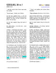
An ad hoc wireless LAN consists of a group of computers, each equipped with a wireless adapter, connected via radio signals as an independent wireless LAN. Computers in a specific ad hoc wireless LAN must therefore be configured to the same radio channel. Figure 2‐1 shows an example of this configuration.
Figure 2-1
2-2
Network Configuration
Ad Hoc Wireless LAN
Network Topologies
Infrastructure Wireless LAN
The access point also provides access to a wired LAN for wireless workstations. An integrated wired/wireless LAN is called an infrastructure configuration. A Basic Service Set (BSS) consists of a group of wireless PC users, and an access point that is directly connected to the wired LAN. Each wireless PC in this BSS can talk to any computer in its wireless group via a radio link, or access other computers or network resources in the wired LAN infrastructure via the access point.
The infrastructure configuration not only extends the accessibility of wireless PCs to the wired LAN, but also increases the effective wireless transmission range for wireless PCs by passing their signal through one or more access points.
A wireless infrastructure can be used for access to a central database, or for connection between mobile workers, as shown in Figure 2‐2.
Figure 2-2
Infrastructure Wireless LAN
RoamAbout RBT-4102 Wireless Access Point Configuration Guide
2-3
Network Topologies
Infrastructure Wireless LAN for Roaming Wireless PCs
The Basic Service Set (BSS) defines the communications domain for each access point and its associated wireless clients. The BSS ID is a 48‐bit binary number based on the access point’s wireless MAC address, and is set automatically and transparently as clients associate with the access point. The BSS ID is used in frames sent between the access point and its clients to identify traffic in the service area. The BSS ID is only set by the access point, never by its clients. The clients only need to set the Service Set Identifier (SSID) that identifies the service set provided by one or more access points. The SSID can be manually configured by the clients, can be detected in an access point’s beacon, or can be obtained by querying for the identity of the nearest access point. For clients that do not need to roam, set the SSID for the wireless card to that used by the access point to which you want to connect.
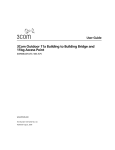
A wireless infrastructure can also support roaming for mobile workers. More than one access point can be configured to create an Extended Service Set (ESS), as shown in Figure 2‐3. By placing the access points so that a continuous coverage area is created, wireless users within this ESS can roam freely. All wireless network card adapters and RBT‐4102s, within a specific ESS, must be configured with the same SSID.
Figure 2-3
2-4
Network Configuration
Infrastructure Wireless LAN for Roaming
Network Topologies
Infrastructure Wireless Bridge
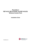
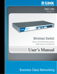
The IEEE 802.11 standard defines a Wireless Distribution System (WDS) for bridge connections between BSS areas (access points). The access point uses WDS to forward traffic on links between units. The access point supports WDS bridge links on either the 5 GHz (802.11a) or 2.4 GHz (802.11b/g) bands and can be used with various external antennas to offer flexible deployment options. Up to six WDS bridge links can be specified for each unit in the wireless bridge network. One unit only must be configured as the “root bridge” in the wireless network. The root bridge should be the unit connected to the main core of the wired LAN. Other bridges must configure one “parent” link to the root bridge or to a bridge connected to the root bridge. The other five available WDS links can be specified as “child” links to other bridges. This forms a tiered‐star topology for the wireless bridge network. When using WDS on a radio band, only wireless bridge units can associate to each other. Wireless clients can only associate with the access point using a radio band set to access point.
Figure 2-4
Infrastructure Wireless Bridge
Network
Core
802.11g Radio
AP Link
Root Bridge
802.11a Radio
Bridge Link
Wireless Bridge Links
Betweeen Access Points
802.11a Radio
Bridge Link
802.11g Radio
AP Link
Bridge
802.11a Radio
Bridge Link
802.11g Radio
AP Link
Bridge
802.11g Radio
AP Link
Bridge
RoamAbout RBT-4102 Wireless Access Point Configuration Guide
2-5
Network Topologies
2-6
Network Configuration
3
Initial Configuration
Overview
You can manage the Enterasys RoamAbout RBT‐4102 with:
•
The Command Line Interface (CLI) accessed through a direct connection to the console port.
For a description of how to use the CLI, and command descriptions, refer to the Enterasys RoamAbout RBT‐4102 Wireless Access Point Command Line Interface Reference Guide.
•
The web interface accessed through a web browser (Internet Explorer V5.0 or above, or Netscape Navigator V6.2 or above).
•
An SNMP manager, such as Enterasys Networks NetSight management applications.
Refer to the Enterasys RoamAbout RBT‐4102 Wireless Access Point Installation Guide for information on the physical setup of the access point.
Note: The default username is admin, and the default password is password, for the CLI and web
management.
Initial Setup Using the CLI
Required Connections
The access point provides an RS‐232 serial port that enables a connection to a PC or terminal for monitoring and configuration. Attach a VT100‐compatible terminal, or a PC running a terminal emulation program to the access point. You can use the console cable provided with this package, or use a cable that complies with the wiring assignments.
To connect to the console port, perform the following steps:
1.
Connect the console cable to the serial port on a terminal, or a PC running terminal emulation software, and tighten the captive retaining screws on the DB‐9 connector.
2.
Connect the other end of the cable to the RS‐232 serial port on the access point.
3.
Make sure the terminal emulation software is set as follows:
• Select the appropriate serial port (COM port 1 or 2).
• Set the data rate to 9600 baud.
• Set the data format to 8 data bits, 1 stop bit, and no parity.
• Set flow control to none.
RoamAbout RBT-4102 Wireless Access Point Configuration Guide
3-1
Initial Setup Using the CLI
• Set the emulation mode to VT100.
• When using HyperTerminal, select Terminal keys, not Windows keys.
Note: When using HyperTerminal with Microsoft® Windows® 2000, make sure that you have
Windows 2000 Service Pack 2 or later installed. Windows 2000 Service Pack 2 fixes the problem of
arrow keys not functioning in HyperTerminal’s VT100 emulation. Go to www.microsoft.com for
information on Windows 2000 service packs.
4.
Once you have set up the terminal correctly, press the Enter key to initiate the console connection. The console login screen is displayed.
For information about the commands refer to the Enterasys RoamAbout RBT‐4102 Wireless Access Point Command Line Interface Reference Guide.
Logging In
To use the CLI to minimally configure the access point, follow these steps:
1.
Enter admin for the user name, and password for the password to log in.
The RBT‐4102 CLI prompt appears.
Username: admin
Password:********
RoamAbout 4102#
Note: The access point requests an IP address from a Dynamic Host Configuration Protocol
(DHCP) server by default. If a DHCP server does not respond, then the access point uses the
default address, 192.168.1.1, which may not be compatible with your network. To assign an IP
address, you must use the CLI. Go to Step 3.
2.
If applicable, set the Country Code. This restricts operation of the access point to the radio channels permitted for wireless networks in the specified country.
Note: Units sold in the United States are configured by default to use only radio channels 1-11 as
defined by FCC regulations. Units sold in other countries are configured by default without a
country code (that is., 99). You must use the CLI to set the country code. Setting the country code
restricts operation of the access point to the radio channels and transmit power levels permitted for
wireless networks in the specified country.
a.
Type country ? to display the list of countries.
RoamAbout 4102#country ?
WORD Country code: AL-ALBANIA, DZ-ALGERIA, AR-ARGENTINA, AM-ARMENIA,
AU-AUSTRALIA, AT-AUSTRIA, AZ-AZERBAIJAN, BH-BAHRAIN, BY-BELARUS,
BE-BELGIUM, BZ-BELIZE, BO-BOLVIA, BR-BRAZIL, BN-BRUNEI DARUSSALAM,
BG-BULGARIA, CL-CHILE, CN-CHINA, CO-COLOMBIA, CR-COSTA RICA,
HR-CROATIA, CY-CYPRUS, CZ-CZECH REPUBLIC, DK-DENMARK, DO-DOMINICAN
REPUBLIC, EC-ECUADOR, EG-EGYPT, SV-EL SALVADOR, EE-ESTONIA, FI-FINLAND,
FR-FRANCE, GE-GEORGIA, DE-GERMANY, GR-GREECE, GT-GUATEMALA,
HN-HONDURAS, HK-HONG KONG, HU-HUNGARY, IS-ICELAND, IN-INDIA,
ID-INDONESIA, IR-IRAN, IE-IRELAND, IL-ISRAEL, IT-ITALY, JP-JAPAN,
JO-JORDAN, KZ-KAZAKHSTAN, KP-NORTH KOREA, KR-KOREA REPUBLIC, KU-KUWAIT,
LV-LATVIA, LB-LEBANON, LI-LIECHTENSTEIN, LT-LITHUANIA, LU-LUXEMBOURG,
MO-MACAU, MK-MACEDONIA, MY-MALAYSIA, MT-MALTA, MC-MONACO, MA-MOROCCO,
NL-NETHERLANDS, NZ-NEW ZEALAND, NO-NORWAY, OM-OMAN, PK-PAKISTAN,
PA-PANAMA, PE-PERU, PH-PHILIPPINES, PL-POLAND, PT-PORTUGAL, PR-PUERTO
3-2
Initial Configuration
Initial Setup Using the CLI
RICO, QA-QATAR, RO-ROMANIA, RU-RUSSIA, SA-SAUDI ARABIA, SG-SINGAPORE,
SK-SLOVAK REPUBLIC, SI-SLOVENIA, ZA-SOUTH AFRICA, ES-SPAIN, SE-SWEDEN,
CH-SWITZERLAND, SY-SYRIA, TW-TAIWAN, TH-THAILAND, TT-TRINIDAD & TOBAGO,
TN-TUNISIA, TR-TURKEY, UA-UKRAINE, AE-UNITED ARAB EMIRATES, GB-UNITED
KINGDOM, UY-URUGUAY, UZ-UZBEKISTAN, VE-VENEZUELA, VN-VIETNAM, YE-YEMEN,
ZW-ZIMBABWE
b.
Determine the code for your country, and then type country followed by your country code (for example, country SG for Singapore).
c.
Reboot the RoamAbout RBT‐4102.
RoamAbout 4102#country SG
Please reset the AP to make the country code change effective
RoamAbout 4102#reset board
Reboot system now? <y/n>: y
3.
If your access point uses a DHCP assigned IP address, go to Step 4 to change the default username and password. Otherwise, disable DHCP for this access point as follows:
a.
Type configure to enter configuration mode.
b.
Type interface ethernet to access the Ethernet interface configuration mode.
RoamAbout 4102#configure
Enter configuration commands, one per line. End with CTRL/Z
RoamAbout 4102(config)#interface ethernet
Enter Ethernet configuration commands, one per line.
RoamAbout 4102(if-ethernet)#
c.
Enter no ip dhcp to disable DHCP.
RoamAbout 4102(if-ethernet)#no ip dhcp
DHCP client state has changed. Please reset AP for change to take effect.
RoamAbout 4102(if-ethernet)#exit
RoamAbout 4102#reset board
Reboot system now? <y/n>: y
Username: admin
Password:********
RoamAbout 4102#configure
Enter configuration commands, one per line. End with CTRL/Z
RoamAbout 4102(config)#interface ethernet
Enter Ethernet configuration commands, one per line.
RoamAbout 4102(if-ethernet)#
d. Set the IP Address. Type ip address ip‐address netmask gateway, where ip‐address is the access point’s IP address, netmask is the network mask for the network, and gateway is the default gateway router. Check with your system administrator to obtain an IP address that is compatible with your network.
RoamAbout 4102(if-ethernet)#ip address ip-address netmask gateway
RoamAbout 4102(if-ethernet)#end
RoamAbout 4102(config)#
After configuring the access point’s IP parameters, you can access the management interface from anywhere within the attached network. The command line interface can also be accessed using Telnet from any computer attached to the network. e.
Go to Step 4.
RoamAbout RBT-4102 Wireless Access Point Configuration Guide
3-3
Initial Setup Using the CLI
4.
Change the default username and password: type username and specify a unique user name; type password and specify a unique password.
RoamAbout 4102(config)#username KarenBD
RoamAbout 4102(config)#password ******
Confirm new password: ******
RoamAbout 4102(config)#
5.
To specify the management VLAN ID, type management‐vlanid and specify a management vlanid.
Note: You must set up the network switch port to support tagged VLAN packets from the access
point. The switch port must also be configured to accept the access point’s management VLAN ID
and native VLAN IDs.
RoamAbout 4102(config)#management-vlanid 10
Reboot system now? <y/n>:y
Username: admin
Password:********
6.
Go to Chapter 4 for advanced configuration.
Using Web Management
Notes:
• The default username is admin, and the default password is password.
• To get help, click on Help, located at the bottom of the screen.
• You must click on the Apply button, located at the bottom of the each Web interface page for the
configuration to take effect.
To use the Web interface to minimally configure the access point, follow these steps:
1.
Open a Web browser and enter the access point’s IP address in the address field:
• If your access point uses a DHCP assigned IP address, make sure the access point is connected to your network, and enter the DHCP assigned IP address in your browser’s address field. Use your DHCP server or other utility to determine the access point’s IP address.
• If your access point uses a static IP address, connect a system to the access point’s Ethernet port and enter the default IP address: http://192.168.1.1/ in your browser’s address field.
The access point’s Login window appears.
2.
3-4
Initial Configuration
Enter the username admin and the password password, and click LOGIN (for more information about the username and password, refer to Chapter 4).
Initial Setup Using the CLI
.
• If applicable, the County Code page appears, go to step 3.
• If the Country Code page does not appear, go to step 4.
3.
If applicable, set the Country:
a.
Click on the arrow in the Country pull‐down menu to select the appropriate country, then click Apply at the bottom of the page.
b.
Click Administration from the menu on the left‐hand side of the page.
The Administration page appears.
RoamAbout RBT-4102 Wireless Access Point Configuration Guide
3-5
Initial Setup Using the CLI
````
c.
Click the Reset button next to Reset Access Point, located at the bottom of the page.
The access point prompts you to confirm that you want to reboot the system.
d. Click OK.
The access point reboots, and the Login window appears.
e.
Enter the username admin and the password password, and click LOGIN.
The Identification window appears.
f.
3-6
Initial Configuration
Go to step 4.
Initial Setup Using the CLI
4.
Enter the following information, and click Apply.
• System Name is an alias used for the access point, enabling the device to be uniquely identified on the network. Default: RoamAbout AP. Length: 1 to 22 characters
• System Location is a text string that describes the system location. Maximum length: 253 characters
• System Contact is a text string that describes the system contact. Maximum length: 253 characters
The access point displays a Settings Saved message. Click OK.
5.
To set a static IP address:
a.
Click TCP/IP Settings from the menu on the left hand side of the page.
The TCP/IP Settings page appears.
RoamAbout RBT-4102 Wireless Access Point Configuration Guide
3-7
Initial Setup Using the CLI
b.
Click the DHCP Client: Disable radio button. DHCP allows you to enable or disable the option to obtain the IP settings for the access point from a DHCP (Dynamic Host Configuration Protocol) server. The IP address, subnet mask, default gateway, and Domain Name Server (DNS) address are dynamically assigned to the access point by the network DHCP server. Default: Enable
c.
Specify the IP Address, Subnet Mask, Default Gateway, and Primary and Secondary DNS.
Note: Enterasys Networks recommends that you reset the access point after changing the
DHCP client status.
‐
IP Address is the IP address of the access point. Valid IP addresses consist of four decimal numbers, 0 to 255, separated by periods. ‐
Subnet Mask is the mask that identifies the host address bits used for routing to specific subnets.
‐
Default Gateway is the IP address of the router for the access point, which is used if the requested destination address is not on the local subnet.
If you have management stations, DNS, RADIUS, or other network servers located on another subnet, type the IP address of the default gateway router in the text field provided. Otherwise, leave the address as all zeros (0.0.0.0).
d. Click Apply at the bottom of the page.
The access point displays a Settings Saved message. e.
3-8
Initial Configuration
Click OK.
Initial Setup Using the CLI
f.
Click Administration from the menu on the left‐hand side of the page.
The Administration page appears.
g.
Click the Reset button next to Reset Access Point, located at the bottom of the page.
The access point prompts you to confirm that you want to reboot the system.
h. Click OK.
The access point reboots.
i.
Type the IP address that you specified for the access point in your browser’s address field. For example, enter http://10.2.101.22/.
The Login window appears.
j.
Enter the username admin and the password password, and click LOGIN.
The Identification page appears.
k.
Click Administration from the menu on the left of the page.
The Administration page appears.
l.
6.
Go to step 6.
Set the username and password.
a.
Click Administration from the menu.
The Administration page appears.
b.
Specify a new username in the Username field.
RoamAbout RBT-4102 Wireless Access Point Configuration Guide
3-9
Initial Setup Using the CLI
c.
Specify a new password in the Password field.
d. Specify the new password again in the Confirm Password field.
e.
Click Apply at the bottom of the page.
The access point displays a Settings Saved message.
f.
7.
Click OK.
To specify the management VLAN ID:
a.
Click Filter Control from the menu.
The Filter Control page appears.
b.
Click the Management VLAN ID: field and enter the VLAN ID from which you will manage the AP. The management VLAN is for managing the access point. For example, the access point allows traffic that is tagged with the specified VLAN to manage the access point via remote management, SSH, SNMP, Telnet, and so forth. VLAN management is enabled by default, and cannot be disabled.
Note: You must set up the network switch port to support tagged VLAN packets from the
access point. The switch port must also be configured to accept the access point’s
management VLAN ID and native VLAN IDs.
c.
8.
3-10
Click Apply at the bottom of the page.
Go to Chapter 4 for advanced configuration.
Initial Configuration
4
Advanced Configuration
Overview
This chapter presents advanced configuration information organized according to the structure of the web interface for easy reference.
Enterasys Networks recommends that you configure a user name and password to control management access to this device as the first advanced configuration step (refer to Administration on page 4‐39).
Table 4‐1 lists the configuration options and brief descriptions.
Using the Web Interface
You must click on the Apply button at the bottom of each Web interface page for the configuration changes on that page to take effect.
Using the Command Line Interface (CLI)
For a description of how to use the CLI, refer to the Enterasys RoamAbout RBT‐4102 Wireless Access Point Command Line Interface Reference Guide.
Table 4-1
Advanced Configuration
Menu
Description
Page
Identification
Specifies the system name, location, and contact.
4-3
TCP / IP Settings
Enables DHCP, or allows you to configure the IP address, subnet
mask, gateway, and domain name servers.
4-5
RADIUS
Configures the RADIUS server for wireless client authentication and
accounting.
4-11
Authentication
Configures the access point as an 802.1x authentication supplicant
with the network.
4-15
Filter Control
Filters communications between wireless clients, access to the
management interface from wireless clients, and traffic matching
specific Ethernet protocol types.
4-18
CDP Settings
Configures the AP to use Cabletron Discovery Protocol (CDP).
4-24
Rogue AP Detection
Scans the airwaves and collects information about access points in
the area.
4-27
RoamAbout RBT-4102 Wireless Access Point Configuration Guide
4-1
Overview
Table 4-1
Advanced Configuration (continued)
Menu
Description
Page
SNMP
Controls access to this access point from management stations
using SNMP, as well as the hosts that will receive trap messages.
4-30
Administration
Configures user name and password for management access;
upgrades software from local file, FTP, or TFTP server; resets
configuration settings to factory defaults; and resets the access
point.
4-39
System Log
Controls logging of error messages; sets the system clock via
SNTP server or manual configuration.
4-45
WDS & STP
Configures bridge mode for each radio interface, and sets spanning
tree parameters.
4-50
802.11a Interface
Configures the IEEE 802.11a interface.
4-56
Radio Settings
Configures radio signal parameters, and service set parameters for
the default interface and up to seven Virtual Access Points (VAPs).
4-56
Security
Configures 802.1x client authentication, with an option for MAC
address authentication, and data encryption with Wired Equivalent
Protection (WEP) or Wi-Fi Protected Access (WPA).
4-78
Configures the IEEE 802.11b/g interface.
4-56
Radio Settings
Configures radio signal parameters, and service set parameters for
the default interface, Wi-Fi Multimedia (WMM), and up to seven
Virtual Access Points (VAPs).
4-56
Security
Configures 802.1x client authentication, with an option for MAC
address authentication, and data encryption with Wired Equivalent
Protection (WEP) or Wi-Fi Protected Access (WPA).
4-78
Displays AP status, CDP status, station status, Neighbor AP
Detection status, WDS-STP status, and event logs.
4-101
802.11b/g Interface
Status
4-2
Advanced Configuration
Identification
Identification
Using Web Management to Configure System Information
The system information parameters for the RBT‐4102 can be left at their default settings. However, modifying these parameters can help you to more easily distinguish different devices in your network.
•
System Name is an alias used for the access point, enabling the device to be uniquely identified on the network. Default: RoamAbout AP. Length: 1‐22 characters
•
System Location is a text string that describes the system location. Maximum length: 253 characters
•
System Contact is a text string that describes the system contact. Maximum length: 253 characters
RoamAbout RBT-4102 Wireless Access Point Configuration Guide
4-3
Identification
Using the CLI to Configure System Information
From the config mode, use the system name command to specify a new system name. Then return to the Executive mode, and use the show system command to display the changes to the system identification settings.
RoamAbout
RoamAbout
RoamAbout
RoamAbout
4102#configure
4102(config)#system name R&D
4102(config)#exit
4102#show system
System Information
====================================================================
Serial Number
: 034830992141
System Up time
: 0 days, 5 hours, 8 minutes, 42 seconds
System Name
: R&D
System Location
:
System Contact
:
System Country Code : SG - SINGAPORE
Ethernet MAC Address : 00-01-F4-61-9C-08
802.11a MAC Address : Default=00-01-F4-61-9C-36 VAP1=00-01-F4-36-3C-36
VAP2=00-01-F4-36-4C-36 VAP3=00-01-F4-36-5C-36
VAP4=00-01-F4-36-6C-36 VAP5=00-01-F4-36-7C-36
VAP6=00-01-F4-36-8C-36 VAP7=00-01-F4-36-9C-36
802.11b/g MAC Address : Default=00-0C-DB-81-3D-CD VAP1=00-0C-DB-81-3D-CE
VAP2=00-0C-DB-81-3D-CF VAP3=00-0C-DB-81-3D-D0
VAP4=00-0C-DB-81-3D-D1 VAP5=00-0C-DB-81-3D-D2
VAP6=00-0C-DB-81-3D-D3 VAP7=00-0C-DB-81-3D-D4
IP Address
: 10.2.43.203
Subnet Mask
: 255.255.0.0
Default Gateway
: 10.2.1.1
Management VLAN ID(AP : 3
IAPP State
: ENABLED
DHCP Client
: DISABLED
HTTP Server
: ENABLED
HTTP Server Port
: 80
HTTPS Server
: ENABLED
HTTPS Server Port
: 443
Slot Status
: Dual band(a/g)
SSH Server
: ENABLED
SSH Server Port
: 22
Telnet Server
: ENABLED
Com Port
: ENABLED
Software Version
: V1.1.51
====================================================================
RoamAbout 4102#
4-4
Advanced Configuration
TCP / IP Settings
TCP / IP Settings
Configuring the RBT‐4102 with an IP address expands your ability to manage the access point. A number of access point features depend on IP addressing to operate.
Note: You can use the web browser interface to access the access point if the access point already
has an IP address that is reachable through your network.
By default, the RBT‐4102 will be automatically configured with IP settings from a Dynamic Host Configuration Protocol (DHCP) server. However, if you are not using a DHCP server to configure IP addressing, use the CLI to manually configure the initial IP values (Refer to Chapter 3, Initial Configuration). After you have network access to the access point, you can use the Web browser interface to modify the IP configuration, if needed.
Note: If there is no DHCP server on your network, then the access point will automatically start up
with its default IP address, 192.168.1.1.
RoamAbout RBT-4102 Wireless Access Point Configuration Guide
4-5
TCP / IP Settings
Using Web Management to Configure TCP/IP
Select TCP/IP Settings from the menu.
•
DHCP allows you to enable or disable the option to obtain the IP settings for the access point from a DHCP (Dynamic Host Configuration Protocol) server. The IP address, subnet mask, default gateway, and Domain Name Server (DNS) address are dynamically assigned to the access point by the network DHCP server. Default: Enable
Note: Enterasys Networks recommends that you reset the access point after changing the DHCP
client status.
•
4-6
IP Address
–
IP Address is the IP address of the access point. Valid IP addresses consist of four decimal numbers, 0 to 255, separated by periods. –
Subnet Mask is the mask that identifies the host address bits used for routing to specific subnets.
–
Default Gateway is the IP address of the router for the access point, which is used if the requested destination address is not on the local subnet.
Advanced Configuration
TCP / IP Settings
If you have management stations, DNS, RADIUS, or other network servers located on another subnet, type the IP address of the default gateway router in the text field provided. Otherwise, leave the address as all zeros (0.0.0.0).
–
•
Primary DNS and Secondary DNS are the IP addresses of the Domain Name Servers (DNS) on the network. A DNS maps numerical IP addresses to domain names and can be used to identify network hosts by familiar names instead of the IP addresses. Web Servers The access point allows the system Web server and the secure Web server to be enabled or disabled, and the TCP port numbers to be set.
Note: If you use HTTP to configure the access point, your connection will be
lost if you disable the HTTP server.
•
–
HTTP Server allows the access point to be monitored or configured from a browser. –
HTTP Port specifies the TCP port to be used by the Web browser interface. Range: 80 or 1024‐65535. Default: 80 –
HTTPS Server allows you to enable or disable the secure HTTP server on the access point. Default: Enabled –
HTTPS Port specifies the UDP port number used for HTTPS/SSL connection to the access pointʹs Web interface. Range: 443 or 1024‐65535. Default: 443
Telnet & SSH Settings Telnet allows you to manage the access point from anywhere in the network. Telnet is not secure from hostile attacks. Therefore, it is recommended to use the Secure Shell (SSH). The SSH protocol uses generated public keys to encrypt all data transfers passing between the access point and SSH‐enabled management station clients and ensures that data traveling over the network arrives unaltered.
–
Telnet Server disables or enables the Telnet server. Default: Enabled.
–
SSH Server disables or enables the SSH server. Default: Enabled.
–
SSH Port sets the UDP port for the SSH server. Range: 1‐22, 24‐79, 81‐442, 444‐2312, 2314‐
65535; Default: 22
Notes:
• The SSH client software needs to be installed on the management station to access the access
point for management via the SSH protocol.
• The access point only supports SSH version 2.0.
• The SSH Port Number range may vary from range specified here; range varies based on default
ports defined on access point and port usage by other applications.
• After software upgrade or configuration reset, the SSH server requires approximately five minutes
to generate host encryption keys. The SSH server is disabled while the keys are being generated.
RoamAbout RBT-4102 Wireless Access Point Configuration Guide
4-7
TCP / IP Settings
•
Ethernet Settings The Ethernet Settings options let you control the speed and duplex setting as well as the auto‐
negotiation state of the Ethernet port.
–
Auto Negotiate disables or enables the negotiation state of the Ethernet port. Default: Enabled.
–
Speed Duplex (Admin) lets you choose from the following: 100Mbps/Full, 100Mbps/Half, 10Mbps/Full, and 10Mbps/Half. Default: 100Mbps/Half when Auto‐negotiation is enabled. –
Speed Duplex (Oper) is the current port status when the Ethernet port is connected to another network device. Default: Dependant on the physical Ethernet port link. Using the CLI to Configure TCP/IP
TCP/IP Configuration
From the config mode, enter the interface configuration mode with the interface ethernet command. Use the ip dhcp command to enable the DHCP client, or no ip dhcp to disable it. To manually configure an address, specify the new IP address, subnet mask, and default gateway using the ip address command. To specify a DNS server address, use the dns server command. Then use the show interface ethernet command from the Executive mode to display the current IP settings.
Example
RoamAbout 4102#configure
Enter configuration commands, one per line. End with CTRL/Z
RoamAbout 4102(config)#interface ethernet
Enter Ethernet configuration commands, one per line.
RoamAbout 4102(if-ethernet)#no ip dhcp
DHCP client state has changed. Please reset AP for change to take effect.
RoamAbout 4102(if-ethernet)#exit
RoamAbout 4102#reset board
Reboot system now? <y/n>: y
Username: admin
Password:********
RoamAbout 4102#configure
Enter configuration commands, one per line. End with CTRL/Z
RoamAbout 4102(config)#interface ethernet
Enter Ethernet configuration commands, one per line.
RoamAbout 4102(if-ethernet)#ip address 192.168.1.2 255.255.255.0 192.168.1.253
RoamAbout 4102(if-ethernet)#dns primary-server 192.168.1.55
RoamAbout 4102(if-ethernet)#dns secondary-server 10.1.0.55
RoamAbout 4102(if-ethernet)#end
RoamAbout 4102(config)#end
RoamAbout 4102#show interface ethernet
Ethernet Interface Information
========================================
IP Address
: 192.168.1.2
Subnet Mask
: 255.255.255.0
Default Gateway
: 192.168.1.253
Primary DNS
: 192.168.1.55
Secondary DNS
: 10.1.0.55
Admin status
: Up
Operational status : Up
4-8
Advanced Configuration
TCP / IP Settings
Untagged VlanId
: 1
========================================
RoamAbout 4102#
SSH Configuration
To enable the SSH server, use the ip ssh‐server enable command from the CLI Ethernet interface configuration mode. To set the SSH server UDP port, use the ip ssh‐server port command. To disable the Telnet server, use the no ip telnet‐server command. To view the current settings, use the show system command from the CLI Executive mode (not shown in the following example).
Example
RoamAbout 4102#configure
Enter configuration commands, one per line. End with CTRL/Z
RoamAbout 4102(config)#interface ethernet
Enter Ethernet configuration commands, one per line.
RoamAbout 4102(if-ethernet)# ip-ssh-server enable
RoamAbout 4102(if-ethernet)# ip-ssh-server port 1124
RoamAbout 4102(if-ethernet)# no ip telnet-server
Ethernet Settings Configuration
To enable or disable auto‐negotiation on the Ethernet port, use the auto‐negotiate enable or auto‐negotiate disable commands, respectively, as shown in the example below.
Note: If the Ethernet port negotiation state is disabled, you must set the port speed and duplex by
using the 'speed-duplex' command.
Example
test4102#configure
Enter configuration commands, one per line. End with CTRL/Z
test4102(config)#int eth
Enter Ethernet configuration commands, one per line.
test4102(if-ethernet)#auto-negotiate disable
test4102(if-ethernet)#speed-duplex ?
10MF
Set speed/duplex to 10Base-T Full Duplex
10MH
Set speed/duplex to 10Base-T Half Duplex
100MF Set speed/duplex to 100Base-TX Full Duplex
100MH Set speed/duplex to 100Base-TX Half Duplex
test4102(if-ethernet)#speed-duplex 100MF
Example
test4102(if-ethernet)#show
Ethernet Interface Information
========================================
IP Address
: 192.168.20.55
Subnet Mask
: 255.255.255.0
Default Gateway
: 192.168.20.2
Primary DNS
: 192.168.20.151
Secondary DNS
: 128.100.56.135
Admin status
: Up
Operational status : Up
Untagged VlanId
: 1
RoamAbout RBT-4102 Wireless Access Point Configuration Guide
4-9
TCP / IP Settings
Auto Negotiate
: Disable
Speed-duplex(Admin) : 100Base-TX Full Duplex
Speed-duplex(Oper) : 100Base-TX Full Duplex
========================================
test4102(if-ethernet)#
4-10
Advanced Configuration
RADIUS
RADIUS
Remote Authentication Dial‐in User Service (RADIUS) is an authentication protocol that uses software running on a central server to control access to RADIUS‐aware devices on the network. An authentication server contains a database of user credentials for each user that requires access to the network.
A primary RADIUS server must be specified for the RBT‐4102 to implement IEEE 802.1x network access control and Wi‐Fi Protected Access (WPA) wireless security. A secondary RADIUS server may also be specified as a backup should the primary server fail or become inaccessible.
In addition, the configured RADIUS server can also act as a RADIUS Accounting server and receive user‐session accounting information from the access point. RADIUS Accounting can be used to provide valuable information on user activity in the network.
If you are using MAC authentication, you must provide the following information to the RADIUS Server Network Administrator:
•
MAC Address of your wireless client. This becomes the username, which is case‐sensitive (lower‐case), and in the format: 00‐01‐f4‐ab‐cd‐ef.
•
Configure the RADIUS server to authenticate using the default password of “NOPASSWORD” for all the MAC address based user names.
Notes:
• This guide assumes that you already configured RADIUS server(s) to support the access point.
Configuration of RADIUS server software is beyond the scope of this guide, refer to the
documentation provided with the RADIUS server software.
• If you are using RADIUS, it is highly recommended that you assign a static IP address to ensure
that the address doesn’t change via DHCP.
RoamAbout RBT-4102 Wireless Access Point Configuration Guide
4-11
RADIUS
Using Web Management to Configure RADIUS
Select RADIUS from the menu.
•
Primary Radius Server Setup configures the following settings to use RADIUS authentication on the access point:
–
IP Address/Server Name specifies the IP address or host name of the RADIUS server. The IP address must be an IP Version 4 address.
–
Port Number is the UDP port number used by the RADIUS server for authentication. This value must match the configuration of your primary RADIUS authentication server. Range: 1024‐65535; Default: 1812
–
Key is the shared text string used to encrypt messages between the access point and the RADIUS server. Be sure that the same text string is specified on the RADIUS server. Do not use blank spaces in the string. Maximum length: 255 characters
–
Timeout (seconds) is the number of seconds the access point waits for a reply from the RADIUS server before re‐sending a request. Range: 1‐60 seconds; Default: 5
–
Retransmit attempts is the number of times the access point tries to re‐send a request to the RADIUS server before authentication fails. Range: 1‐30; Default: 3
Note: For the Timeout and Retransmit attempts fields, accept the default values unless you
experience problems connecting to the RADIUS server over the network.
4-12
Advanced Configuration
RADIUS
•
–
RADIUS Accounting enables or disables the AP to send RADIUS accounting information for clients to the RADIUS accounting server. Default: Disable
–
Accounting Port specifies the specific destination port for RADIUS accounting packets. A value between 1024 and 65535. This value must match the configuration of your primary RADIUS accounting server. Default: 1813
–
Interim Update Timeout determines how often to send accounting updates from the access point to the server for this session. This value can be overridden by the RADIUS server. Default: 3600 seconds (one hour), Range: 60 seconds (one minute) to 86400 seconds (one day).
Secondary Radius Server Setup is used to configure a second RADIUS server to provide a backup in case the primary server fails. The access point uses the secondary server if the primary server fails or becomes inaccessible. Once the access point switches over to the secondary server, it periodically attempts to establish communication again with primary server. If communication with the primary server is re‐established, the secondary server reverts to a backup role.
The RADIUS Accounting features supported by this access point are standard and non‐vendor specific. For a full understanding of RADIUS Accounting attributes supported, refer to RFC 2865. Table 4‐2 describes the RADIUS attributes that are used by the access point.
Table 4-2
RADIUS Attributes
RADIUS Accounting Attribute
Description
Acct-Status-Type
Contains the RADIUS Accounting message type:
• Start
• Stop
• Interim-Update
• Accounting-On
• Accounting-Off
Acct-Input-Octets
Contains the cumulative input byte count for the
session.
Acct-Output-Octets
Contains the cumulative output byte count for the
session.
Acct-Session-Id
Contains a unique Accounting ID for a given
session.
Acct-Authentic
Indicates the method used to authenticate, currently
only RADIUS is supported.
Acct-Session-Time
Contains the time in seconds that the user has
received service.
Acct-Input-Packets
Contains the cumulative input packet count for the
session.
Acct-Output-Packets
Contains the cumulative output packet count for the
session.
User-Name
Contains the user’s identity.
Class
Sent by the server to the client in an Access-Accept
message.
RoamAbout RBT-4102 Wireless Access Point Configuration Guide
4-13
RADIUS
Table 4-2
RADIUS Attributes (continued)
RADIUS Accounting Attribute
Description
NAS Identifier
Hard coded identifier of the RADIUS Accounting
client.
Acct-Interim-Interval
Indicates the number of seconds between each
interim update in seconds for the given session.
Using the CLI to Configure RADIUS
From the global configuration mode, use the radius‐server address command to specify the address of the primary RADIUS server, or the radius‐server secondary address command to specify the address of the secondary RADIUS server. (The following example configures settings for the primary RADIUS server.) Use the radius‐server or radius server secondary and key, port, port‐accounting, retransmit, timeout, and timeout‐interim commands to configure the other RADIUS server parameters. Use the show radius command from the Executive mode to display the current settings for the primary and secondary RADIUS servers.
Example
RoamAbout
RoamAbout
RoamAbout
RoamAbout
RoamAbout
RoamAbout
RoamAbout
RoamAbout
RoamAbout
RoamAbout
4102#configure
4102(config)#radius-server
4102(config)#radius-server
4102(config)#radius-server
4102(config)#radius-server
4102(config)#radius-server
4102(config)#radius-server
4102(config)#radius-server
4102(config)#exit
4102#show radius
address 192.168.1.25
port 1812
key green
timeout 10
retransmit 5
port-accounting 1813
timeout-interim 500
Radius Server Information
========================================
IP
: 192.168.1.25
Port
: 181
Key
: *****
Retransmit
: 5
Timeout
: 10
Accounting Port : 1813
InterimUpdate vv: 500
========================================
Radius Secondary Server Information
========================================
IP
: 0.0.0.0
Port
: 1812
Key
: *****
Retransmit
: 3
Timeout
: 5
Accounting Port : DISABLED
InterimUpdate vv: 3600
========================================
RoamAbout 4102#
4-14
Advanced Configuration
Authentication
Authentication
Wireless clients can be authenticated for network access by checking their MAC address against the local database configured on the access point, or by using a database configured on a central RADIUS server. Alternatively, authentication can be implemented using the IEEE 802.1X network access control protocol. Client station MAC authentication occurs prior to the IEEE 802.1X authentication procedure configured for the access point. However, a client’s MAC address provides relatively weak user authentication, since MAC addresses can be easily captured and used by another station to break into the network. Using 802.1X provides more robust user authentication using user names and passwords or digital certificates. So, although you can configure the access point to use MAC address and 802.1X authentication together, it is better to choose one or the other, as appropriate. Use MAC address authentication for a small network with a limited number of users. MAC addresses can be manually configured on the access point itself without the need to set up a RADIUS server. Use IEEE 802.1X authentication for networks with a larger number of users and where security is the most important issue. For 802.1X authentication a RADIUS server is required in the wired network to control the user credentials of the wireless clients.
The access point can also operate in an 802.1X supplicant mode. This enables the access point itself to be authenticated with a RADIUS server using a configured MD5 user name and password. This prevents rogue access points from gaining access to the network.
RoamAbout RBT-4102 Wireless Access Point Configuration Guide
4-15
Authentication
Using Web Management to Configure Authentication
Select Authentication from the menu.
•
802.1x Supplicant allows you to enable or disable the access point as an 802.1x authentication supplicant to authenticate with the network.
If enabled, you must specify:
4-16
–
Username: the username that the access point uses to authenticate to the network. Range: 1 to 32 characters
–
Password: the password that the access point uses to authenticate to the network. Range: 1 to 32 characters
Advanced Configuration
Authentication
Using the CLI to Configure Authentication
Use the 802.1x supplicant user command from the global configuration mode to specify the username and password that the access points uses for authentication with the network. Use the 802.1x supplicant command to enable the access point as an 802.1x supplicant. To display the current settings, use the show authentication command from the Executive mode. Use the no 8021.x supplication command from the global configuration mode to disable.
Example
RoamAbout 4102#configure
Enter configuration commands, one per line. End with CTRL/Z
RoamAbout 4102(config)#802.1x supplicant user
User Name<1-32> : RBT4102-AND
Password<1-32> :password
Confirm password<1-32> :password
RoamAbout 4102(config)#802.1x supplicant
RoamAbout 4102(config)#
RoamAbout 4102(config)#exit
RoamAbout 4102#show authentication
802.11a Authentication Server Information
VAP AuthMode SessionTimeout Password
Default Local MAC
========================================================================
Default LOCAL
0 min
*****
ALLOWED
1
LOCAL
0 min
*****
ALLOWED
2
LOCAL
0 min
*****
ALLOWED
3
LOCAL
2 min
*****
ALLOWED
4
LOCAL
0 min
*****
ALLOWED
5
LOCAL
0 min
*****
ALLOWED
6
LOCAL
0 min
*****
ALLOWED
7
LOCAL
0 min
*****
ALLOWED
802.11b/g Authentication Server Information
VAP AuthMode SessionTimeout Password
Default Local MAC
========================================================================
Default LOCAL
0 min
*****
ALLOWED
1
LOCAL
0 min
*****
ALLOWED
2
LOCAL
0 min
*****
ALLOWED
3
LOCAL
0 min
*****
ALLOWED
4
LOCAL
0 min
*****
ALLOWED
5
LOCAL
0 min
*****
ALLOWED
6
LOCAL
0 min
*****
ALLOWED
7
LOCAL
0 min
*****
ALLOWED
802.1x Supplicant Information
========================================================================
802.1x supplicant
: ENABLED
802.1x supplicant user
: RBT4102-AND
802.1x supplicant password
: *****
MAC Address Filter Status List in SSID
802.11a 802.11b/g
Index MAC Address
Status
01234567 01234567
===== ================= ========= ======== ========
1 00-01-f4-88-b3-d7 ALLOWED ******** ********
2 00-00-11-22-33-44 ALLOWED *------- *------===================================================
RoamAbout 4102(config)#
RoamAbout RBT-4102 Wireless Access Point Configuration Guide
4-17
Filter Control and VLANs
Filter Control and VLANs
The access point can employ VLAN ID and network traffic frame filtering to control access to network resources and increase security. You can prevent communications between wireless clients and prevent access point management from wireless clients. Also, you can block specific Ethernet traffic from being forwarded by the access point. Using Web Management to Configure Filter Control and VLANs
Select Filter Control from the menu.
4-18
Advanced Configuration
Filter Control and VLANs
•
Management VLAN ID specifies the management VLAN ID for the access point.
The management VLAN is for managing the access point. For example, the access point allows traffic that is tagged with the specified VLAN to manage the access point via remote management, SSH, SNMP, Telnet, and so forth. VLAN management is enabled by default, and cannot be disabled.
Note: You must set up the network switch port to support tagged VLAN packets from the access
point. The switch port must also be configured to accept the access point’s management VLAN ID
and native VLAN IDs.
•
Ethernet Untagged VLAN ID specifies the VLAN ID to which the AP maps untagged packets entering through the APʹs Ethernet port. Range: 1 to 4094
•
IAPP (Inter Access Point Protocol) enables the protocol signaling required for wireless clients to roam between different 802.11f‐compliant access points. Select Disable to disable 802.11f signaling. Default: Enable.
•
IBSS Relay Control, in conjunction with radio interface and Virtual AP (VAP) IBSS settings, controls whether clients associated with an interface or VAP can establish wireless communications with clients associated with other interfaces or VAPs. Default: All VAP mode
•
•
–
In All VAP Mode, clients associated with any IBSS enabled radio interfaces or VAPs can establish wireless communications with each other.
–
In Per VAP Mode, clients associated with a specific IBSS enabled radio interface or VAP can establish wireless communications with other clients associated with the same interface or VAP. For example, clients associated with VAP1 can establish wireless communications with each other but not with clients associated with an IBSS enabled VAP2.
Wireless AP Management controls management access to the RBT‐4102 from wireless clients. Management interfaces include the Web, Telnet, or SNMP. Default: Allow
–
Disable permits management access from wireless clients. The default setting.
–
Enable blocks management access from wireless clients. Ethernet Type Filter controls checks on the Ethernet type of all incoming and outgoing Ethernet packets against the protocol filtering table. Default: Disable
–
Disable: The access point does not filter Ethernet protocol types.
–
Enable: The access point filters Ethernet protocol types based on the configuration of protocol types in the filter table. If a protocol has its status set to “ON,” in the filter table, the access point filters that protocol.
–
Local Management lists the Ethernet protocols.
–
ISO Designator specifies the ISO designators for each Ethernet protocol listed.
–
Status indicates, by radio button selection, whether the access point filters this Ethernet protocol. ON indicates filtering for this Ethernet protocol. Off indicates no filtering for this Ethernet protocol.
Note: Ethernet protocol types not listed in the filtering table are always forwarded by the access
point.
RoamAbout RBT-4102 Wireless Access Point Configuration Guide
4-19
Filter Control and VLANs
Using the CLI to Configure Filter Control and VLANs
CLI Commands for VLAN Support
From the global configuration mode, use the management‐vlanid command to set the default Management VLAN ID for the Ethernet interface. VLAN tagging is enabled by default, and cannot be disabled. To view the current management VLAN settings, use the show system command.
Example
RoamAbout 4102#configure
Enter configuration commands, one per line. End with CTRL/Z
RoamAbout 4102(config)#management-vlanid 3
Reboot system now? <y/n>: y
Username: admin
Password:********
RoamAbout 4102#show system
System Information
====================================================================
Serial Number
: 034830992141
System Up time
: 0 days, 5 hours, 8 minutes, 42 seconds
System Name
: R&D
System Location
:
System Contact
:
System Country Code : SG - SINGAPORE
Ethernet MAC Address : 00-01-F4-61-9C-08
802.11a MAC Address : Default=00-01-F4-61-9C-36 VAP1=00-01-F4-36-3C-36
VAP2=00-01-F4-36-4C-36 VAP3=00-01-F4-36-5C-36
VAP4=00-01-F4-36-6C-36 VAP5=00-01-F4-36-7C-36
VAP6=00-01-F4-36-8C-36 VAP7=00-01-F4-36-9C-36
802.11b/g MAC Address : Default=00-0C-DB-81-3D-CD VAP1=00-0C-DB-81-3D-CE
VAP2=00-0C-DB-81-3D-CF VAP3=00-0C-DB-81-3D-D0
VAP4=00-0C-DB-81-3D-D1 VAP5=00-0C-DB-81-3D-D2
VAP6=00-0C-DB-81-3D-D3 VAP7=00-0C-DB-81-3D-D4
IP Address
: 10.2.43.203
Subnet Mask
: 255.255.0.0
Default Gateway
: 10.2.1.1
Management VLAN ID(AP : 3
IAPP State
: ENABLED
DHCP Client
: DISABLED
HTTP Server
: ENABLED
HTTP Server Port
: 80
HTTPS Server
: ENABLED
HTTPS Server Port
: 443
Slot Status
: Dual band(a/g)
SSH Server
: ENABLED
SSH Server Port
: 22
Telnet Server
: ENABLED
Com Port
: ENABLED
Software Version
: V1.1.51
====================================================================
RoamAbout 4102#
4-20
Advanced Configuration
Filter Control and VLANs
From the interface ethernet mode, use the untagged‐vlanid to specify a VLAN ID for the AP to use for untagged packets entering through the AP’s Ethernet port. Use the show interface command from the Executive mode to view untagged‐vlanid status.
RoamAbout 4102#configure
Enter configuration commands, one per line. End with CTRL/Z
RoamAbout 4102(config)#interface ethernet
Enter Ethernet configuration commands, one per line.
RoamAbout 4102(if-ethernet)#untagged-vlanid 10
RoamAbout 4102(if-ethernet)#exit
RoamAbout 4102#show interface
Ethernet Interface Information
========================================
IP Address
: 10.2.43.203
Subnet Mask
: 255.255.0.0
Default Gateway
: 10.2.1.1
Primary DNS
: 134.141.93.21
Secondary DNS
: 134.141.79.92
Admin status
: Up
Operational status : Up
Untagged VlanId
: 10
========================================
RoamAbout 4102#
RoamAbout RBT-4102 Wireless Access Point Configuration Guide
4-21
Filter Control and VLANs
CLI Commands for Filtering
Use the filter ibss‐relay command from the global configuration to set the mode for wireless‐to‐
wireless communications through the access point. Use the filter wireless‐ap‐manage command to restrict management access from wireless clients. Use the iapp or no iapp commands to enable or disable clients from roaming between access points. To configure Ethernet protocol filtering, use the filter ethernet‐type filter enable command to enable filtering and the filter ethernet‐type protocol <protocol> command to define the protocols that you want to filter. To remove a protocol filter from the table, use the no filter ethernet‐type protocol <protocol> command. To display the current settings, use the show filters command from the Executive mode.
Example
RoamAbout 4102#configure
Enter configuration commands,
RoamAbout 4102(config)#filter
RoamAbout 4102(config)#filter
RoamAbout 4102(config)#filter
RoamAbout 4102(config)#exit
RoamAbout 4102#show filters
one per line. End with CTRL/Z
wireless-ap-manage
ethernet-type enable
ethernet-type protocol CDP
Protocol Filter Information
===========================================================
IBSS Relay Control
:All VAP Mode
802.11a VAP0 :ENABLED
802.11b/g VAP0 :ENABLED
VAP1 :ENABLED
VAP1 :ENABLED
VAP2 :ENABLED
VAP2 :ENABLED
VAP3 :ENABLED
VAP3 :ENABLED
VAP4 :ENABLED
VAP4 :ENABLED
VAP5 :ENABLED
VAP5 :ENABLED
VAP6 :ENABLED
VAP6 :ENABLED
VAP7 :ENABLED
VAP7 :ENABLED
Wireless AP Management :ENABLED
Ethernet Type Filter
:ENABLED
Enabled Protocol Filters
----------------------------------------------------------Protocol: CDP
ISO: 0x2000
===========================================================
RoamAbout 4102#
4-22
Advanced Configuration
Filter Control and VLANs
SVP Commands
To enable SVP, from the global configuration mode, use the svp command. To disable SVP, use the no version of the command. Use the show svp command from the Executive mode to view the SVP status.
Example
RoamAbout 4102#configure
Enter configuration commands, one per line. End with CTRL/Z
RoamAbout 4102(config)#svp
RoamAbout 4102(config)#
RoamAbout 4102(config)#no svp
RoamAbout 4102(config)#exit
RoamAbout 4102#show svp
SVP:
Disabled
RoamAbout 4102#
RoamAbout RBT-4102 Wireless Access Point Configuration Guide
4-23
CDP Settings
CDP Settings
Cabletron Discovery Protocol (CDP) settings control how the AP uses CDP to discover neighbors on the physical LAN to which it connects. Using Web Management to Configure CDP
Select CDP Settings from the menu. The CDP Settings page appears.
Note: The Port Status overrides the Global Status. Make the same selections for both global and
port status or make sure the port status settings match the behavior you want.
•
Global Settings:
–
Global Status
‐
Disable ‐ disables this AP from using CDP. ‐
Enable ‐ enables this AP to use CDP and to send information about itself at the specified Transmit Frequency.
–
Auto ‐ enables this AP to use CDP and to send information about itself when it receives hello packets. Default: Auto –
Hold Time (15‐600) ‐ specifies amount of time in seconds that the AP retains neighbor entry after receiving last hello packet. Default: 180 –
Transmit Frequency (5‐900) ‐ the interval in seconds between AP transmission of CDP hello packets. Default: 60 ‐
4-24
Advanced Configuration
Authentication Key specifies a character string of up to 16‐bytes to use as an authentication key for CDP packets.
CDP Settings
•
Port Status: –
Disable ‐ disables this AP from using CDP. –
Enable ‐ enables this AP to use CDP and to send information about itself at the specified Transmit Frequency. –
Auto ‐ enables this AP to use CDP and to send information about itself only when neighbors request information. Default: Auto
Note: The Port Status overrides the Global Status. Make the same selections for both the global
and port status or make sure the port status settings match the behavior you want
RoamAbout RBT-4102 Wireless Access Point Configuration Guide
4-25
CDP Settings
Using the CLI to Configure CDP
From the global configuration mode, enable cdp with the cdp auto‐enable or cdp enable commands. Specify the hold time, transmit frequency and optionally an authentication code using the cdp hold‐time, cdp tx‐frequency and cdp authentication commands. To disable cdp, use the cdp disable command. Use the show cdp command from Executive mode to display cdp settings, or to view neighbor entries or cdp traffic statics.
Example
RoamAbout 4102#configure
Enter configuration commands, one per line. End with CTRL/Z
RoamAbout 4102(config)#cdp enable
RoamAbout 4102(config)#cdp hold-time 360
RoamAbout 4102(config)#cdp tx-frequency 120
RoamAbout 4102(config)#cdp authentication tC3Jc
RoamAbout 4102(config)#exit
RoamAbout 4102#show cdp
CDP Global Information
========================================
Global Status
: Enable
Authentication Code : tC3Jc
Transmit Frequency : 120 secs
Hold Time
: 360 secs
========================================
RoamAbout 4102#show cdp neighbor
CDP Neighbor Information
=================================================================
Last Change Time
: 7 days, 20 hours, 29 minutes, 26 seconds
Last Deletion Time
: 7 days, 20 hours, 28 minutes, 50 seconds
--------------------------------------------------------------------Neighbor IP Address : 10.2.191.52
Neighbor MAC Address : 00-E0-63-BB-93-C2
Time Mark
: 0 days, 0 hours, 0 minutes, 57 seconds
Device Type
: Dot1d Bridge
Description
: Enterasys Networks 6H303-48 Rev 05.05.01 03/14/03--11:10 ofc
Port
: 14
--------------------------------------------------------------------Neighbor IP Address : 10.2.43.200
Neighbor MAC Address : 00-01-F4-61-9B-F2
Time Mark
: 7 days, 20 hours, 29 minutes, 26 seconds
Device Type
: RoamAbout Wireless Access Point
Description
: RoamAbout AP ; SW version: V1.0.17
Port
: 1
=====================================================================
RoamAbout 4102#show cdp traffic
CDP Traffic Information
========================================
Input Packets
: 27283
Output Packets
: 16677
Invalid Version Packets : 0
Parse Error Packets
: 0
Transmit Error Packets : 0
Memory Error Packets
: 0
========================================
4-26
Advanced Configuration
Rogue AP Detection
Rogue AP Detection
This feature scans the airwaves and collects information about access points in the area.
The term “rogue AP” is used to describe an access point that is not authorized to participate on the network. It may not have the proper security settings in place. Rogue AP’s can potentially allow unauthorized users access to the network. In addition, a legitimate client may mistakenly associate to a rogue AP with invalid encryption settings and not to the AP that has been configured for it to use. This can cause a denial of service problem.
It lists access points found during the scan on the Neighbor AP Detection Status page after the scan is complete.
If you enable the RADIUS authentication setting, this feature also identifies rogue APs. It performs a RADIUS server look up for the MAC address of each access point found. It reports access points whose MAC addresses it finds in the RADIUS server on the Neighbor AP Detection Status page. It reports access points whose MAC addresses it does not find as rogue APs in the syslog. Refer to System Log on page 4‐45. Rogue access points can be identified by unknown BSSID (MAC address) or SSID configuration
Using Web Management to Configure Rogue AP Detection
Select Rogue AP Detection from the menu. The Rogue AP Detection selections are displayed in the following screen.
RoamAbout RBT-4102 Wireless Access Point Configuration Guide
4-27
Rogue AP Detection
•
RADIUS Authentication enables the access point to discover rogue access points. Enabling RADIUS Authentication causes the access point to check the MAC address/Basic Service Set Identifier (BSSID) of each access point that it finds against a RADIUS server to determine whether the access point is allowed. With RADIUS authentication disabled, the access point can identify its neighboring access points only; it cannot identify whether the access points are allowed or are rogues. If you enable RADIUS authentication, you must configure a RADIUS server for this access point.
•
AP Scan Interval specifies the wait‐time between scans. Range: 30 to 10080 minutes. Default: 720 minutes between scans.
•
AP Scan Duration sets the length of time for each rogue AP scan. A long scan duration time will detect more access points in the area, but causes more disruption to client access. Range: 100‐ 1000 milliseconds. Default: 350 milliseconds. •
Scan Now button starts an immediate rogue AP scan for the specified radio interface.
•
Scan All button scans for all 802.11a and 802.11b/g interfaces.
Note: When the access point scans a channel for neighbor AP’s, wireless clients will not be able to
connect to the access point. Frequent scanning, or scans, of a long duration will degrade the
access points performance. Therefore, avoid frequent scanning, or scans, of long duration unless
there is a reason to believe that more intensive scanning is required to find a rogue AP.
Using the CLI to Configure Rogue AP Detection
Use the rogue‐ap command to detect neighboring access points and access points that are not authorized to participate on the network. Use the interface‐a command to set access point detection parameters for 802.11a interfaces. Use the interface‐g command to set access point detection parameters for 802.11b/g interfaces. Set up the rogue AP feature by specifying the scan duration; interduration (amount of time to make frequency channels active to clients); and the interval between scans. To use rogue AP detection, enable radius authentication using the radius command. To initiate a Rogue AP scan for all interfaces, use the scan command. Use the show rogue‐ap command from the Executive mode to view interface‐a and interface‐g settings and to view scan results for both interfaces.
Example
RoamAbout 4102#configure
Enter configuration commands, one per line. End with CTRL/Z
RoamAbout 4102(config)#rogue-ap radius enable
RoamAbout 4102(config)#rogue-ap interface-g enable
configure either syslog or trap or both to receive the rogue APs detected.
RoamAbout 4102(config)#rogue-ap interface-g duration 200
RoamAbout 4102(config)#rogue-ap interface-g interval 120
RoamAbout 4102(config)#rogue-ap interface-g interduration 2000
RoamAbout 4102(config)#rogue-ap interface-g scan
RoamAbout 4102(config)#exit
RoamAbout 4102#show rogue-ap
802.11a : Rogue AP Setting
========================================================================
Rogue AP Detection
: Disabled
Rogue AP Authentication
: Enabled
Rogue AP Scan Interval
: 720 minutes
Rogue AP Scan Duration
: 350 milliseconds
Rogue AP Scan InterDuration: 3000 milliseconds
4-28
Advanced Configuration
Rogue AP Detection
802.11a : Rogue AP Status
No. AP Address(BSSID)
SSID
Channel(MHz) RSSI Encr.
========================================================================
IBSS
802.11b/g : Rogue AP Setting
==============================================================================
Rogue AP Detection
: Enabled
Rogue AP Authentication
: Enabled
Rogue AP Scan Interval
: 120 minutes
Rogue AP Scan Duration
: 200 milliseconds
Rogue AP Scan InterDuration: 2000 milliseconds
802.11b/g : Rogue AP Status
No. AP Address(BSSID)
SSID
Channel(MHz) RSSI Encr.
========================================================================
1 00-00-01-81-05-00 TalentAP
6(2437 MHz)
14
2 00-01-e6-ff-f4-d1 Enterprise AP
11(2462 MHz)
2
3 00-04-e2-5f-f4-31 Nana
10(2457 MHz)
10
Yes
4 00-04-e2-9c-74-be AP2552W_2
1(2412 MHz)
1
5 00-0b-ac-e7-b2-91 overlapper
3(2422 MHz)
3
Yes
6 00-12-0e-14-91-4b Spiderman
11(2462 MHz)
12
7 00-12-a9-d5-a6-61 abcde
11(2462 MHz)
12
8 00-12-bf-10-c7-be RD12
3(2422 MHz)
3
Yes
9 00-30-b4-01-59-03 RD15
6(2437 MHz)
10
Yes
10 00-30-f1-9f-06-3d TT5
5(2432 MHz)
6
11 00-70-46-00-00-03 DavidAP
1(2412 MHz)
2
Yes
RoamAbout 4102#
IBSS
RoamAbout RBT-4102 Wireless Access Point Configuration Guide
4-29
SNMP
SNMP
The access point includes an on‐board agent that supports SNMP versions 1, 2c, and 3. Access to the on‐board agent using SNMP v1 and v2c is controlled by community strings. To communicate with the access point, a management station must first submit a valid community string for authentication.
Access to the on‐board agent using SNMP v3 provides additional security features that cover message integrity, authentication, and encryption; as well as controlling notifications that are sent to specified user targets.
You can use a network management application such as Enterasys Networks NetSight Console to manage the RBT‐4102 via SNMP from a network management station.
To implement SNMP management, the RBT‐4102 must have an IP address and subnet mask, configured manually or dynamically. Once an IP address has been configured, appropriate SNMP communities and trap receivers should be configured.
Using Web Management to Configure SNMP
Select SNMP from the menu.
4-30
Advanced Configuration
SNMP
•
SNMP allows you to enable or disable SNMP management access and also enables the access point to send SNMP traps (notifications). SNMP management is enabled by default.
•
SNMPv1 allows you to enable or disable management access from SNMPv1 clients.
•
Community Name (Read Only) defines the SNMP community access string that has read‐only access. Authorized management stations are only able to retrieve MIB objects. Default: public, maximum length: 23 characters, case sensitive
•
Community Name (Read/Write) defines the SNMP community access string that has read/write access. Authorized management stations are able to both retrieve and modify MIB objects. Default: private, maximum length: 23 characters, case sensitive
•
Trap Destination (1 to 4) enables or disables each of the four available trap destinations. If enabled, you must define the trap destination using the IP address and community name fields.
•
Trap Destination IP Address (1 to 4) specifies the recipient of SNMP notifications. Enter the IP address or the host name. Host Name: 1 to 20 characters
•
Trap Destination Community Name specifies the community string sent with the notification operation. Default: public, maximum length: 23 characters, case sensitive
•
Trap Configuration allows selection of specific SNMP notifications to send. Table 4‐3 lists the available notifications.
Table 4-3
SNMP Notifications
Notification
Description
sysSystemUp
The access point is up and running.
sysSystemDown
The access point is about to shutdown and reboot.
sysRadiusServerChanged
The access point was changed from the primary RADIUS
server to the secondary, or from the secondary to the primary.
dot11StationAssociation
A client station successfully associated with the access point.
dot11StationReAssociation
A client station successfully re-associated with the access
point.
dot11StationAuthentication
A client station was successfully authenticated.
dot11StationRequestFail
A client station failed association, re-association, or
authentication.
dot1xAuthFail
A 802.1x client station failed RADIUS authentication.
dot1xMacAddrAuthSuccess
A client station successfully authenticated its MAC address
with the RADIUS server.
dot11InterfaceAFail
The 802.11a interface failed.
sntpServerFail
The access point failed to set the time from the configured
SNTP server.
dot1xMacAddrAuthFail
A client station failed MAC address authentication with the
RADIUS server.
dot1xAuthNotInitiated
A client station did not initiate 802.1x authentication.
dot1xAuthSuccess
A 802.1x client station successfully authenticated by the
RADIUS server.
RoamAbout RBT-4102 Wireless Access Point Configuration Guide
4-31
SNMP
Table 4-3
SNMP Notifications (continued)
localMacAddrAuthSuccess
A client station successfully authenticated its MAC address
with the local database on the access point.
localMacAddrAuthFail
A client station failed authentication with the local MAC address
database on the access point.
iappStationRoamedFrom
A client station roamed from another access point (identified by
its IP address).
iappStationRoamedTo
A client station roamed to another access point (identified by its
IP address).
iappContextDataSent
A client station’s Context Data was sent to another access
point with which the station has associated.
dot11InterfaceGFail
The 802.11g interface failed.
dot11WirelessSTPDetection
A wireless STP packet has been detected.
•
•
Engine‐ID is used for SNMPv3 to identify the access point in a network of multiple access points. –
Entering the Engine‐ID invalidates all engine IDs that have been previously configured.
–
If the Engine‐ID is deleted or changed, all SNMP users will be cleared. You will need to reconfigure all users.
SNMP Users allows you configure the security requirement of users access.
Note: If you are going to use Group Lists, you must set up the Groups before adding the SNMP
users.
4-32
Advanced Configuration
SNMP
–
User specifies string to identify an SNMP user. (32 characters maximum)
–
Group is the name of the SNMP group to which the user is assigned (32 characters maximum). There are three pre‐defined groups: RO, RWAuth, or RWPriv.
–
Auth Type specifies the authentication type used for user authentication: “md5” or “none.”
–
Priv Type is the encryption type used for SNMP data encryption: Either DES or none. If DES is selected, a key must be entered in the Passphrase field.
–
Passphrase is the user password required when data encryption, Priv Type, is used (8 to 32 characters).
–
Action: Add adds a new user. Edt allows you to edit an existing user, Del deletes the user.
•
SNMP Groups allows you to combine the users into groups of authorization and privileges. Users must be assigned to groups that have the same security levels. If a user who has “AuthPriv” security (uses authentication and encryption) is assigned to a read‐only (RO) group, the user will not be able to access the database. An AuthPriv user must be assigned to the RWPriv group with the AuthPriv security level.
•
Group List is the list of groups for SNMP v3 users. The access point enables SNMP v3 users to be assigned to three pre‐defined groups. The available groups are:
–
RO is a read‐only group using no authentication and no data encryption. Users in this group use no security, authentication or encryption, in SNMP messages they send to the agent. This is the same as SNMP v1 or SNMP v2c.
–
RWAuth is a read/write group using authentication, but no data encryption. Users in this group send SNMP messages that use an MD5 key/password for authentication, but not a DES key/password for encryption.
–
RWPriv is a read/write group using authentication and data encryption. Users in this group send SNMP messages that use an MD5 key/password for authentication and a DES key/password for encryption. Both the MD5 and DES key/passwords must be defined.
–
Security Level
–
–
‐
noAuthNoPriv — A read‐only level using no authentication and no data encryption. Users assigned to this group use no security, either authentication or encryption, in SNMP messages they send to the agent. This is the same as SNMP v1 or SNMP v2c.
‐
authNoPriv — A read/write level using authentication, but no data encryption. Users assigned to this group send SNMP messages that use an MD5 password for authentication, but not a DES key for encryption. ‐
authPriv — A read/write group using authentication and data encryption. Users assigned to this group send SNMP messages that use an MD5 password for authentication and a DES key for encryption. Both the MD5 password and DES key must be defined.
WriteView — Specifies an SNMPv3 write view for the group
‐
None: No view specified indicates read‐only access.
‐
Write: Users in the group have write access to all objects.
Action — Adds a new group; Edt allows you to edit an existing group; Del deletes the group.
RoamAbout RBT-4102 Wireless Access Point Configuration Guide
4-33
SNMP
•
•
4-34
SNMP Targets
–
Target ID is the name you enter to identify the SNMP target. Maximum: 32 characters
–
IP Address is the IP address of the user. –
UDP port is the UDP port of the server.
–
SNMP user is the name of the user. This name must match the name you entered in SNMP Users.
–
Filter ID is the filter ID that you entered in the SNMP Filter section.
–
Action Add adds a new target; Edt allows you to edit an existing target; Del deletes the target.
SNMP Filter
–
New Filter is the name you enter to identify a filter that includes or excludes certain notifications. Maximum: 32 characters.
–
Filter Type specifies whether the filter includes or excludes the specified notification. Includes means that notifications that are part of the subtree will be filtered out. Exclude means that notifications that are part of the subtree will be sent.
–
Subtree is an OID string that specifies the family of subtrees included or excluded by this filter. The string must be preceded with a period (.). For example, .1.3.6.1.
–
Action Add adds a filter; Edt allows you to edit an existing filter; Del deletes the filter.
Advanced Configuration
SNMP
Using the CLI to Configure SNMP
The access point includes an on‐board agent that supports SNMP versions 1, 2c, and 3. Access to the on‐board agent using SNMP v1 and v2c is controlled by community strings. To communicate with the access point, a management station must first submit a valid community string for authentication.
Refer to the Enterasys RoamAbout RBT‐4102 Wireless Access Point Command Line Interface Reference Guide, for a complete list of SNMP commands.
CLI Commands for SNMP
Use the snmp‐server enable server command from the global configuration mode to enable SNMP. You can use the snmp‐server v1 enable command to prevent access from SNMPv1 clients. To set read/write and read‐only community names, use the snmp‐server community command. The snmp‐server host command defines trap receiver hosts and the snmp‐server trap command enables or disables specific traps.
Examples
RoamAbout 4102#configure
Enter configuration commands, one per line. End with CTRL/Z
RoamAbout 4102(config)#snmp-server enable server
RoamAbout 4102(config)#snmp-server v1 disable
RoamAbout 4102(config)#snmp-server community alpha rw
RoamAbout 4102(config)#snmp-server community beta ro
RoamAbout 4102(config)#snmp-server host 1 192.168.1.9 alpha
RoamAbout 4102(config)#snmp-server trap dot11StationAssociation
RoamAbout 4102(config)#
To view the current SNMP settings, use the show snmp command.
RoamAbout 4102#show snmp
SNMP Information
==============================================
Service State
: Enable
Community (ro)
: *****
Community (rw)
: *****
EngineId
:80:00:07:e5:80:00:00:2e:62:00:00:00:18
EngineBoots:1
Trap Destinations:
1:
192.168.1.9,
2:
0.0.0.0,
3:
0.0.0.0,
4:
0.0.0.0,
Community:
Community:
Community:
Community:
dot11InterfaceAFail
dot11StationAssociation
dot11StationReAssociation
dot11WirelessSTPDetection
dot1xAuthNotInitiated
dot1xMacAddrAuthFail
iappContextDataSent
iappStationRoamedTo
Enabled
Enabled
Enabled
Enabled
Enabled
Enabled
Enabled
Enabled
*****,
*****,
*****,
*****,
State:
State:
State:
State:
Enabled
Disabled
Disabled
Disabled
dot11InterfaceGFail
dot11StationAuthentication
dot11StationRequestFail
dot1xAuthFail
dot1xAuthSuccess
dot1xMacAddrAuthSuccess
iappStationRoamedFrom
localMacAddrAuthFail
Enabled
Enabled
Enabled
Enabled
Enabled
Enabled
Enabled
Enabled
RoamAbout RBT-4102 Wireless Access Point Configuration Guide
4-35
SNMP
localMacAddrAuthSuccess
sntpServerFail
systemDown
Enabled
Enabled
Enabled
pppLogonFail
radiusServerChanged
systemUp
Enabled
Enabled
Enabled
=============================================
RoamAbout 4102#
CLI Commands for Configuring SNMPv3 Users and Groups
Use the snmp‐server engine‐id command to define the SNMP v3 engine before creating groups or assigning users to groups. Use the snmp‐server group command to create groups with a specific security level. Use the snmp‐server user command to create and assign users to groups. To view the current SNMP v3 engine ID, use the show snmp command.
Examples
RoamAbout 4102(config)#snmp-server engine-id 1a:2b:3c:4d:00:ff
RoamAbout 4102(config)#snmp-server group
Group Name<1-32>
:TPS
1. NoAuthNoPriv
2. AuthNoPriv
3. AuthPriv
Select the security level<1,2,3>: [1]:3
Write right<none,write, NULL>
:write
RoamAbout 4102(config)#
RoamAbout 4102(config)#snmp-server user
User Name<1-32>
:chris
Group Name<1-32>
:TPS
md5(Auth) Passphrase<8-32>:a good secret
des(Priv) Passphrase<8-32>:a very good secret
RoamAbout 4102(config)#
To view SNMP users and group settings, use the show snmp users, show snmp groups, or show snmp group‐assignments commands.
RoamAbout 4102#show snmp groups
GroupName
:RO
SecurityModel :USM
SecurityLevel :NoAuthNoPriv
GroupName
:TPS
SecurityModel :USM
SecurityLevel :AuthPriv
GroupName
:RWAuth
SecurityModel :USM
SecurityLevel :AuthNoPriv
GroupName
:RWPriv
SecurityModel :USM
SecurityLevel :AuthPriv
RoamAbout 4102#show snmp users
=============================================
UserName
:chris
GroupName
:TPS
AuthType
:MD5
4-36
Advanced Configuration
SNMP
Passphrase:****************
PrivType
:DES
Passphrase:****************
=============================================
RoamAbout 4102#show snmp group-assignments
GroupName
:TPS
UserName
:chris
RoamAbout 4102#
RoamAbout RBT-4102 Wireless Access Point Configuration Guide
4-37
SNMP
CLI Commands for Configuring SNMPv3 Targets
To create a notification target, use the snmp‐server targets command from the CLI configuration mode. To assign a filter to a target, use the snmp‐server filter‐assignment command. To view the current SNMP targets, use the show snmp target command from the CLI Executive mode. To view filter assignment to targets, use the show snmp filter‐assignments command.
Example
RoamAbout
RoamAbout
RoamAbout
RoamAbout
4102(config)#snmp-server targets mytraps 192.168.1.33 chris
4102(config)#snmp-server filter-assignment mytraps
trapfilter
4102(config)#exit
4102#show snmp target
Host ID
: mytraps
User
: chris
IP Address
: 192.168.1.33
UDP Port
: 162
=============================
RoamAbout 4102#show snmp filter-assignments
HostID
mytraps
FilterID
trapfilter
RoamAbout 4102#
CLI Commands for Configuring SNMPv3 Trap Filters
To create a notification filter, use the snmp‐server filter command from the CLI configuration mode. Use the command more than once with the same filter ID to build a filter that includes or excludes multiple MIB objects. To view the current SNMP filters, use the show snmp filter command from the CLI Executive mode.
Example
RoamAbout 4102(config)#snmp-server filter trapfilter include .1
RoamAbout 4102(config)#snmp-server filter trapfilter exclude
.1.3.6.1.2.1.2.2.1.1.23
RoamAbout 4102(config)#exit
RoamAbout 4102#show snmp filter
Filter: trapfilter
Type: include
Subtree: iso
Type: exclude
Subtree: iso.3.6.1.2.1.2.2.1.1.23
=============================
RoamAbout 4102#
4-38
Advanced Configuration
Administration
Administration
Changing the Password
Management access to the Web and CLI interface on the RBT‐4102 is controlled through a single user name and password. You can also gain additional access security by disabling the com port after configuring the AP, and using control filters (refer to “Filter Control and VLANs” on page 4‐18).
To protect access to the management interface, you should change the user name and password as soon as possible. If the user name and password are not configured, then anyone having access to the access point may be able to compromise access point and network security. Note: Pressing the Reset button on the back of the access point for more than five seconds resets
the user name and password to the factory defaults. For this reason, it is recommend that you
protect the access point from physical access by unauthorized persons.
RoamAbout RBT-4102 Wireless Access Point Configuration Guide
4-39
Administration
Using Web Management to Change the Password
Select Administration from the menu.
•
•
Change Username/Password A username and password are required to configure the access point. Enterasys Networks strongly recommends that you change your password from the default value to ensure network security. –
Username is the name of the user. The default name is “admin”. Length: 3‐16 characters, case sensitive.
–
New Password is the password for management access. Length: 3‐16 characters, case sensitive.
–
Confirm New Password requires you to re‐enter the password for verification.
Reset Username/Password
Restore from default resets the username and/or the password back to the default settings. The default username is admin and the default password is password.
4-40
Advanced Configuration
Administration
Using the CLI to Change the Password
Use the username and password commands from the CLI configuration mode.
Example
RoamAbout
RoamAbout
RoamAbout
RoamAbout
RoamAbout
4102(config)#username John
4102(config)#password ****
4102(config)#confirm password ****
4102(config)#exit
4102#
Enabling and Disabling Com Port
To provide more security for the access point, management access through the console port can be disabled. Default: Enable
Using Web Management to Enable and Disable Com Port
Use the Com Port Status radio buttons to enable or disable console port access.
Using the CLI to Enable and Disable Com Port
Use the com‐port command from the CLI configuration mode.
Example
RoamAbout 4102(config)#com-port disable
RoamAbout 4102(config)#exit
RoamAbout 4102#
RoamAbout RBT-4102 Wireless Access Point Configuration Guide
4-41
Administration
Upgrading Firmware
You can upgrade the RBT‐4102 software from a local file on the management workstation, or from an FTP or TFTP server. New software may be provided periodically on the Wireless Web site (http://www.enterasys.com/products/wireless). After upgrading new software, you must reboot the RBT‐4102 to implement the new code. Until a reboot occurs, the RBT‐4102 will continue to run the software it was using before the upgrade started.
Before upgrading new software, verify that the RBT‐4102 is connected to the network and has been configured with a compatible IP address and subnet mask.
Bulk upgrades can be done using Enterasys Networks NetSight Inventory Manager. If you need to download from an FTP or TFTP server, perform the following additional tasks:
4-42
•
Obtain the IP address of the FTP or TFTP server where the access point software is stored.
•
Verify that the image is in the appropriate directory on the server.
•
If upgrading from an FTP server, be sure that you have an account configured on the server with a user name and password.
•
If VLANs are configured on the access point, determine the VLAN ID with which the FTP or TFTP server is associated, and then configure the management station, or the network port to which it is attached, with the same VLAN ID. If you are managing the access point from a wireless client, the VLAN ID for the wireless client must be configured on a RADIUS server.
Advanced Configuration
Administration
Using Web Management to Upgrade Firmware
•
Current version displays the version number of code.
•
Local downloads an operation code image file from the Web management station to the access point using HTTP. Specify the name of the code file in the New firmware file field, either:
•
•
–
Use the Browse button to locate the image file locally on the management station.
–
Enter the name of the code file on the server. The new firmware file name should not contain slashes (\ or /), the leading letter of the file name should not be a period (.), and the maximum length for file names is 32 characters for files on the access point. (Valid characters: A‐Z, a‐z, 0‐9, “.”, “‐”, “_”).
–
Click Start Upgrade to download file.
Remote downloads an operation code image file from a specified remote FTP or TFTP server. –
Click the radio button beside FTP or TFTP server.
–
IP Address specifies the IP address or host name of FTP or TFTP server.
–
Username specifies the user ID for login on an FTP server.
–
Password specifies the password used for login on an FTP server.
–
Click Start Upgrade to download file.
Restore Factory Settings resets the configuration settings to the factory default settings (all configuration settings will be lost), and then you must reboot the system. Caution: If you restore factory defaults, all user-configured information will be lost. You will have
to re-enter the default user name (admin) to regain management access to this device.
•
Reset Access Point reboots the system, and retains your configuration settings. Note: If you have upgraded system software, then you must reboot the RBT-4102 to implement the
new operation code.
RoamAbout RBT-4102 Wireless Access Point Configuration Guide
4-43
Administration
Using the CLI to Upgrade Firmware
To download software from a TFTP/FTP Server, use the copy command from the Executive mode. The copy command requires you to specify either the file type and then the server type, or the server type and then the file type. You must then specify the file name, and IP address of the TFTP server. When the download is complete, you can use the dir command to check that the new file is present in the access point file system. To run the new software, use the reset board command to reboot the access point.
Example
RoamAbout 4102#
RoamAbout 4102#copy tftp file
1. Application image
2. Config file
3. Boot block image
Select the type of download<1,2,3>: [1]:1
TFTP Source file name:ets-img_v1017.bin
TFTP Server IP:10.120.112.2
Firmware version of system is V1.0.16 and Updating Run-Time code v01.00.17 NOW!
This firmware is compatible with hardware.
The software was properly copied over to the system and a reset is needed in order
for the software changes to take place.
RoamAbout 4102#
4-44
Advanced Configuration
System Log
System Log
The RBT‐4102 can be configured to send event and error messages to a System Log Server. The system clock can also be synchronized with a time server, so that all the messages sent to the Syslog server are stamped with the correct time and date.
The RBT‐4102 supports a logging process that can control error messages saved to memory or sent to a Syslog server. The logged messages serve as a valuable tool for isolating access point and network problems.
Using Web Management to Configure System Log
Select System Log from the menu.
•
System Log Setup enables the logging of error messages. Default: Disable
•
Server (1, 2, 3, 4) enables the sending of log messages to a Syslog server host.Default: Disable
•
–
Server Name/IP is the IP address or name of a Syslog server.
–
Server UDP Port specifies the UDP port to use on that server.
Logging Console enables the logging of error messages to the console.
RoamAbout RBT-4102 Wireless Access Point Configuration Guide
4-45
System Log
•
Logging Level sets the severity level for event logging.
•
Logging Facility‐Type specifies the syslog facility to use for messages, (16 to 23) local 0 to local 7.
The system allows you to limit the messages that are logged by specifying a minimum severity level. Table 4‐4 lists the error message levels from the most severe (Emergency) to least severe (Debug). The message levels that are logged include the specified minimum level up to the Emergency level.
Table 4-4
Logging Level Descriptions
Error Level
Description
Emergency
Immediate action needed
Alerts
Immediate action needed
Critical
Critical conditions (such as, memory allocation, or free memory error - resource
exhausted)
Error
Error conditions (such as, invalid input, or default used)
Warning
Warning conditions (such as, return false, or unexpected return)
Notice
Normal but significant condition, such as cold start
Informational
Informational messages only
Debug
Debugging messages
Note: The access point error log can be viewed using the Event Logs window in the Status section
(refer to “Using Web Management to View Event Logs” on page 4-115).The Event Logs window
displays the last 128 messages logged in chronological order, from the newest to the oldest. Log
messages are erased when the device is rebooted.
4-46
Advanced Configuration
System Log
Using the CLI to Configure System Log
To enable logging on the access point, use the logging on command from the global configuration mode. The logging level command sets the minimum level of message to log. Use the logging console command to enable logging to the console. Use the logging host command to specify the Syslog servers. The logging facility‐type command sets the facility‐type number to use on the Syslog server. To view the current logging settings, use the show logging command.
Examples
RoamAbout 4102#configure
Enter configuration commands, one per line. End with CTRL/Z
RoamAbout 4102(config)#logging on
RoamAbout 4102(config)#logging level alert
RoamAbout 4102(config)#logging console
RoamAbout 4102(config)#logging host 1 10.1.0.3 1024
RoamAbout 4102(config)#logging facility-type 19
RoamAbout 4102(config)#exit
RoamAbout 4102#show logging
Logging Information
============================================
Syslog State
: Enabled
Logging Console State
: Enabled
Logging Level
: Alert
Logging Facility Type
: 19
Servers
1: 10.1.0.3, UDP Port: 1024, State: Enabled
2: 0.0.0.0, UDP Port: 514, State: Disabled
3: 0.0.0.0, UDP Port: 514, State: Disabled
4: 0.0.0.0, UDP Port: 514, State: Disabled
=============================================
RoamAbout 4102#
RoamAbout RBT-4102 Wireless Access Point Configuration Guide
4-47
System Log
Using Web Management to Configure SNTP
Simple Network Time Protocol (SNTP) allows the RBT‐4102 to set its internal clock based on periodic updates from a time server. Maintaining an accurate time on the access point enables the system log to record meaningful dates and times for event entries.
The RBT‐4102 acts as an SNTP client, periodically sending time synchronization requests to specific time servers. You can configure up to two time server IP addresses. The access point will attempt to poll each server in the configured sequence.
To configure SNTP, select System Log from the menu, and scroll down to SNTP Server.
•
SNTP Server configures the access point to operate as an SNTP client. When enabled, at least one time server IP address must be specified. When disabled, you manually set the date and time of the system clock.
–
Primary Server is the IP address of an SNTP time server that the access point attempts to poll for a time update. Default: 137.92.140.80
–
Secondary Server is the IP address of a secondary SNTP time server. The access point first attempts to update the time from the primary server; if this fails it attempts an update from the secondary server. Default: 192.43.244.18
Note: If SNTP is disabled, you can manually set the date and time of the system clock.
–
•
4-48
Set Time (SNTP Server disabled) allows you to manually set the current date and time for the location of this access point.
Set Time Zone. SNTP uses Coordinated Universal Time (or UTC, formerly Greenwich Mean Time, or GMT) based on the time at the Earth’s prime meridian, zero degrees longitude.
–
Enter Time Zone sets a time corresponding to your local time. You must indicate the number of hours your time zone is located before (East) or after (West) UTC.
–
Enable Daylight Saving provides a way to automatically adjust the system clock for Daylight Savings Time changes. To use this feature you must define the month and date to begin and to end the change from standard time. During this period the system clock is set back by one hour.
Advanced Configuration
System Log
Using the CLI to Configure SNTP
To enable SNTP support on the access point, from the global configuration mode specify SNTP server IP addresses using the sntp‐server ip command, then use the sntp‐server enable command to enable the service. Use the sntp‐server timezone command to set the time zone for your location, and the sntp‐server daylight‐saving command to set daylight savings. To view the current SNTP settings, use the show sntp command from the Executive mode.
Examples
RoamAbout 4102#configure
Enter configuration commands, one per line. End with CTRL/Z
RoamAbout 4102(config)#sntp-server ip 1 10.1.0.19
RoamAbout 4102(config)#sntp-server enable
RoamAbout 4102(config)#sntp-server timezone +8
RoamAbout 4102(config)#sntp-server daylight-saving
Enter Daylight saving from which month<1-12>: 3
and which day<1-31>: 31
Enter Daylight saving end to which month<1-12>: 10
and which day<1-31>: 31
RoamAbout 4102(config)#exit
RoamAbout 4102#show sntp
SNTP Information
=========================================================
Service State
: Enabled
SNTP (server 1) IP: 10.1.0.19
SNTP (server 2) IP: 192.43.244.18
Current Time
: 19 : 35, Oct 10th, 2003
Time Zone
: +8 (TAIPEI, BEIJING)
Daylight Saving : Enabled, from Mar, 31th to Oct, 31th
=========================================================
RoamAbout 4102#
The following example shows how to manually set the system time when SNTP server support is disabled on the access point.
RoamAbout 4102#configure
Enter configuration commands, one per line. End with CTRL/Z
RoamAbout 4102(config)#no sntp-server enable
RoamAbout 4102(config)#sntp-server date-time
Enter Year<1970-2100>: 2003
Enter Month<1-12>: 10
Enter Day<1-31>: 10
Enter Hour<0-23>: 18
Enter Min<0-59>: 35
RoamAbout 4102(config)#exit
RoamAbout 4102#
RoamAbout RBT-4102 Wireless Access Point Configuration Guide
4-49
WDS and STP
WDS and STP
Each access point radio interface can be configured to operate in a bridge mode, which allows it to forward traffic directly to other access point units. To set up bridge links between access point units, you must configure the Wireless Distribution System (WDS) forwarding table by specifying the wireless MAC address of all units to which you want to forward traffic. You can specify up to eight WDS bridge links for each unit in the wireless bridge network. The Spanning Tree Protocol (STP) can be used to detect and disable network loops, and to provide backup links between bridges. This allows a wireless bridge to interact with other bridging devices (that is, an STP‐compliant switch, bridge or router) in your network to ensure that only one route exists between any two stations on the network, and provide backup links which automatically take over when a primary link goes down.
4-50
Advanced Configuration
WDS and STP
Using Web Management to Configure WDS and STP
Select WDS & STP from the menu.
RoamAbout RBT-4102 Wireless Access Point Configuration Guide
4-51
WDS and STP
•
WDS Bridge allows you to specify up to eight WDS bridge links (MAC addresses) per radio interface for each unit in the wireless bridge network. One unit must be configured as the “root bridge” in the wireless network. The root bridge is the unit connected to the main core of the wired LAN. Other bridges need to specify one “Parent” link to the root bridge or to a bridge connected to the root bridge. The other seven WDS links are available as “Child” links to other bridges.
–
•
Bridge Role allows you to set each radio interface to operate in one of the following modes: (Default: AP)
‐
AP (Access Point) to operate as an access point for wireless clients, providing connectivity to a wired LAN.
‐
Bridge to operate as a bridge to other access points. The “Parent” link to the root bridge must be configured. Up to seven other ”Child” links are available to other bridges.
‐
Root Bridge to operate as the root bridge in the wireless bridge network. Up to eight ”Child” links are available to other bridges in the network.
–
Channel Auto Sync allows the AP in the Bridge mode (the ʺChildʺ AP) to automatically reconnect with its ʺParentʺ AP (or the Root‐Bridge) in the event that either the ʺChildʺ or the ʺParentʺ APʹs channel is changed. Default: Disabled.
–
Bridge Parent is the physical layer address of the root bridge unit or the bridge unit connected to the root bridge. (12 hexadecimal digits in the form “xx‐xx‐xx‐xx‐xx‐xx”)
–
Bridge Child is the physical layer address of other bridge units for which this unit serves as the bridge parent or the root bridge. (12 hexadecimal digits in the form “xx‐xx‐xx‐xx‐xx‐
xx”)
Spanning Tree Protocol uses a distributed algorithm to select a bridging device (STP‐compliant switch, bridge or router) that serves as the root of the spanning tree network. It selects a root port on each bridging device (except for the root device) which incurs the lowest path cost when forwarding a packet from that device to the root device. Then it selects a designated bridging device from each LAN which incurs the lowest path cost when forwarding a packet from that LAN to the root device. All ports connected to designated bridging devices are assigned as designated ports. After determining the lowest cost spanning tree, it enables all root ports and designated ports, and disables all other ports. Network packets are therefore only forwarded between root ports and designated ports, eliminating any possible network loops.
Once a stable network topology has been established, all bridges listen for Hello BPDUs (Bridge Protocol Data Units) transmitted from the root bridge. If a bridge does not get a Hello BPDU after a predefined interval (Maximum Age), the bridge assumes that the link to the root bridge is down. This bridge will then initiate negotiations with other bridges to reconfigure the network to reestablish a valid network topology.
–
Bridge enables/disables STP on the wireless bridge. Default: Disabled
–
Bridge Priority is used in selecting the root device, root port, and designated port. The device with the highest priority becomes the STP root device. However, if all devices have the same priority, the device with the lowest MAC address will then become the root device. Note: Note that lower numeric values indicate higher priority.
4-52
Advanced Configuration
WDS and STP
–
–
–
–
–
‐
Range: 0‐65535
‐
Default: 32768
Bridge Max Age is the maximum time (in seconds) a device can wait without receiving a configuration message before attempting to reconfigure. All device ports (except for designated ports) should receive configuration messages at regular intervals. Any port that ages out STP information (provided in the last configuration message) becomes the designated port for the attached LAN. If it is a root port, a new root port is selected from among the device ports attached to the network. Range: 6‐40 seconds
‐
Default: 20
‐
Minimum: The higher of 6 or [2 x (Hello Time + 1)].
‐
Maximum: The lower of 40 or [2 x (Forward Delay ‐ 1)]
Bridge Hello Time is the interval (in seconds) at which the root device transmits a configuration message. Range: 1‐10 seconds
‐
Default: 2
‐
Minimum: 1
‐
Maximum: The lower of 10 or [(Max. Message Age / 2) ‐1]
Bridge Forward Delay is the maximum time (in seconds) this device waits before changing states (for example, discarding to learning to forwarding). This delay is required because every device must receive information about topology changes before it starts to forward frames. In addition, each port needs time to listen for conflicting information that would make it return to a discarding state; otherwise, temporary data loops might result. Range: 4‐30 seconds
‐
Default: 15
‐
Minimum: The higher of 4 or [(Max. Message Age / 2) + 1]
‐
Maximum: 30
Link Path Cost is used by the STP to determine the best path between devices. Therefore, lower values should be assigned to ports attached to faster media, and higher values assigned to ports with slower media. Path cost takes precedence over port priority.
‐
Range: 1‐65535
‐
Default: Ethernet interface: 19; Wireless interface: 40
Link Port Priority defines the priority used for this port in the Spanning Tree Protocol. If the path cost for all ports on a switch are the same, the port with the highest priority (for example, lowest value) will be configured as an active link in the spanning tree. This makes a port with higher priority less likely to be blocked if the Spanning Tree Protocol is detecting network loops. Where more than one port is assigned the highest priority, the port with lowest numeric identifier will be enabled.
‐
Default: 128
‐
Range: 0‐255, in steps of 16
RoamAbout RBT-4102 Wireless Access Point Configuration Guide
4-53
WDS and STP
Using the CLI to Configure WDS
To set the role of the access point radio interface, use the bridge role command from the CLI wireless interface configuration mode. Then, configure the MAC addresses of the child links to other nodes using the bridge‐link child command. If the radio interface role is set to Bridge, the MAC address of the parent node must also be configured using the bridge‐link parent command. To view the current bridge link settings, use the show bridge link command.
Examples
RoamAbout 4102#configure
Enter configuration commands, one per line. End with CTRL/Z
RoamAbout 4102(config)#interface wireless a
Enter Wireless configuration commands, one per line.
RoamAbout 4102(if-wireless a)# bridge-role bridge
RoamAbout 4102(if-wireless a)#bridge-link child 2
00-08-3e-84-bc-6d
RoamAbout 4102(if-wireless a)#bridge-link child 3
00-08-3e-85-13-f2
RoamAbout 4102(if-wireless a)#bridge-link child 4
00-08-3e-84-79-31
RoamAbout 4102(if-wireless a)#bridge-link parent
00-08-2d-69-3a-51
RoamAbout 4102(if-wireless a)#exit
RoamAbout 4102#show bridge link wireless a
Interface Wireless A WDS Information
====================================
AP Role: Bridge
Parent: 00-08-2d-69-3a-51
Child:
Child 2: 00-08-3e-84-bc-6d
Child 3: 00-08-3e-85-13-f2
Child 4: 00-08-3e-84-79-31
Child 5: 00-00-00-00-00-00
Child 6: 00-00-00-00-00-00
STAs:
No WDS Stations.
RoamAbout 4102#
If the radio interface role is set to parent, the MAC address of the bridge child must be configured using the bridge child command. To view the current bridge link settings, use the show interface wireless a or the show interface wireless b command.
Example
RoamAbout 4102#configure
Enter configuration commands, one per line. End with CTRL/Z
RoamAbout 4102(config)#int wire a
Enter Wireless configuration commands, one per line.
RoamAbout 4102(if-wireless a)#channel 52
RoamAbout 4102(if-wireless a)#ssid WDSLink-A
RoamAbout 4102(if-wireless a)#bridge role root-bridge
RoamAbout 4102(if-wireless a)#bridge child 1 00-11-88-06-32-A8
RoamAbout 4102(if-wireless a)#authentication OPEN
RoamAbout 4102(if-wireless a)#enc
RoamAbout 4102(if-wireless a)#key 1 64 ascii 12345
RoamAbout 4102(if-wireless a)#transmit-key 1
RoamAbout 4102(if-wireless a)#no shutdown
RoamAbout 4102(if-wireless a)#exit
4-54
Advanced Configuration
WDS and STP
Using the CLI to Configure STP
If a radio interface is set to the Bridge or Root Bridge role, STP can be enabled on the access point to maintain a valid network topology. To globally enable STP, use the bridge stp enable command from the CLI configuration mode. Then, configure the other global STP parameters for the bridge. The path cost and priority for each bridge link can be set using the bridge‐link path‐cost and bridge‐link port‐priority command from the Wireless Interface configuration mode. The path cost and priority can also be set for the Ethernet port from the Ethernet Interface configuration mode. To view the current STP settings, use the show bridge stp command.
Example
RoamAbout 4102#configure
Enter configuration commands, one per line. End with CTRL/Z
RoamAbout 4102(config)#bridge stp enable
RoamAbout 4102(config)#bridge stp forwarding-delay 25
RoamAbout 4102(config)#bridge stp hello 5
RoamAbout 4102(config)#bridge stp max-age 40
RoamAbout 4102(config)#bridge stp pri 40000
RoamAbout 4102(config)#interface wireless a
Enter Wireless configuration commands, one per line.
RoamAbout 4102(if-wireless a)#bridge-link path-cost 2 40
RoamAbout 4102(if-wireless a)#bridge-link port-priority 2 64
RoamAbout 4102(if-wireless a)#exit
RoamAbout 4102#show bridge stp
Bridge MAC
: 00:11:88:06:37:35
Status
: Enabled
priority
: 40000
designated-root
: priority = 40000, MAC = 00:11:88:06:37:35
root-path-cost
: 0
root-Port-no
: 0
Hold Time
:
1 Seconds
Hello Time
:
5 Seconds
Maximum Age
:
40 Seconds
Forward Delay
:
25 Seconds
bridge Hello Time
:
5 Seconds
bridge Maximum Age
:
40 Seconds
bridge Forward Delay :
25 Seconds
time-since-top-change: 1269 Seconds
topology-change-count: 33
RoamAbout 4102#sho bridge link wire a 2
Port-No
: 19
status
: Enabled
state
: Forwarding
priority
: 64
path cost
: 40
message age Timer
: Inactive
message age
: 1450
designated-root
: priority = 40000, MAC = 00:11:88:06:37:35
designated-cost
: 0
designated-bridge : priority = 40000, MAC = 00:11:88:06:37:35
designated-port
: priority = 64, port No = 19
forward-transitions : 1
RoamAbout 4102#
RoamAbout RBT-4102 Wireless Access Point Configuration Guide
4-55
Radio Interface
Radio Interface
The IEEE 802.11a and 802.11b/g interfaces include configuration options for radio signal characteristics, Virtual APs (VAPs), and wireless security features. The configuration options for both radio interfaces are nearly identical, and are both covered in this section of the manual.
The Radio Settings section includes options for the radio characteristics of the interface, and the network definition of the default radio interface, Wi‐Fi Multimedia (WMM), and up to seven VAPs per radio interface.
Radio Signal Characteristics
The access point can operate in several different radio modes, IEEE 802.11a only, 802.11b only, 802.11g only, 802.11b/g only, or a mixed 802.11a/b/g mode. 802.11g is backward compatible with 802.11b.
Note: The radio channel settings for the RBT-4102 are limited by local regulations, which determine
the number of channels that are available.
The IEEE 802.11a interface operates within the 5 GHz band, at up to 54 Mbps.
You define network information and radio signal characteristics for the radio interface. The network information applies only to the Service Set Identifier (SSID) specified for the default radio interface. You specify unique network information for the SSID of each VAP you define for this radio interface (in addition to the default radio interface), if any.
4-56
Advanced Configuration
Radio Interface
Radio Settings
Using Web Management to Configure Interface Radio Settings
Select Radio Settings under the type of interface (802.11a or 802.11b/g) that you want to configure. Note: The WMM and Virtual AP fields (not shown here) are discussed later in this section.
•
Interface Status disables/enables use of this default radio interface. Default: Enable.
Notes: Before enabling the radio card, you must set the country selection, if applicable, using the
CLI. For more information, see the Enterasys RoamAbout Wireless RBT-4102 Installation Guide.
You must enable the default radio interface in order to configure VAPs on this radio interface.
•
Description is the description you provide to identify this default radio interface.
•
Network Name (SSID) The name of the basic service set provided by a VAP interface. Clients that want to connect to the network through the access point must set their SSID to the same as that of an access point VAP interface. Default: VAP_TEST_11A (0 to 3). Range: 1‐32 characters.
RoamAbout RBT-4102 Wireless Access Point Configuration Guide
4-57
Radio Interface
•
Native VLAN ID is the VLAN ID for this default radio interface. The access point assigns this VLAN ID to all client traffic using this radio interface unless you assign unique VLAN IDs to clients through the RADIUS server using RFC 3580 (Section 3.31) tunnel attributes.
Using RFC 3580 (Section 3.31) tunnel attributes, you must configure user VLAN IDs (1‐4094) on the RADIUS server for each client authorized to access the network. The RADIUS server then assigns a VLAN ID to a client after successful authentication using IEEE 802.1x and a central RADIUS server. If a client does not have a configured VLAN ID, the access point assigns the client to the native VLAN ID for the radio interface. The default is 1.
When setting up VLAN IDs for each user on the RADIUS server, be sure to use the RADIUS attributes and values as indicated in Table 4‐5.
Table 4-5
VLAN ID RADIUS Attributes
Number
RADIUS Attribute
Value
64
Tunnel-Type
VLAN (13)
65
Tunnel-Medium-Type
802
81
Tunnel-Private-Group-ID
VLANID (1 to 4094 in hexadecimal)
Note: The specific configuration of RADIUS server software is beyond the scope of this guide.
Refer to the documentation provided with the RADIUS server software.
•
•
Secure Access specifies whether clients can access the default radio interface network by discovering and automatically configuring the SSID, or whether clients must be already configured with the SSID. Default: Disable
–
Enable denies access to wireless clients that do not have the default radio interface network name (SSID) already configured. This default radio interface does not broadcast its network name, so that clients with operating systems like Windows XP do not see the name show up in wireless LAN configuration dialogs. –
Disable broadcasts its network name, and clients can discover and use the SSID to access this default radio interface’s wireless network. IBSS Relay: In conjunction with IBSS Relay Control settings (see Filter Control and VLANs on page 4‐18), controls whether clients associated with the default radio interface can establish wireless communications with each other through the AP. Default: Disable
If you enable IBSS Relay, clients can establish wireless communications with each other through the AP. If you set the IBSS Relay Control to All VAP, then clients associated with all IBSS enabled radio interfaces or VAPs can establish wireless communications with each other. If you set the IBSS Relay Control to Per VAP, only the clients associated with the same (IBSS enabled) radio interface or VAP can communicate with each other. •
Maximum Associations (0‐255) specifies the number of clients allowed to associate with this radio interface. •
Fixed Antenna Control selects the use of two diversity antennas or a single antenna. Default: Diversity
–
4-58
Diversity. The radio uses both antennas in a diversity system. Select this method when the Antenna ID is set to “Default Antenna” to use the access pointʹs integrated antennas. The access point does not support external diversity antennas.
Advanced Configuration
Radio Interface
–
Right. The radio only uses the antenna on the right side (the side closest to the access point LEDs). Select this method when using an optional external antenna that is connected to the right antenna connector.
–
Left. The radio only uses the antenna on the left side (the side farthest from the access point LEDs). The access point does not support an external antenna connection on its left antenna. Therefore, this method is not valid for the access point. Note: The Antenna ID must be selected in conjunction with the Antenna Control Method to
configure proper use of any of the antenna options.
•
Antenna ID selects the antenna to be used by the access point; either the integrated diversity antennas (the default antenna) or an optional external antenna. The optional external antennas (if any) that are certified for use with the access point are listed in the drop‐down menu. Selecting the correct antenna ID ensures that the access point’s radio transmissions are within regulatory power limits for the country of operation. When an external antenna is selected, the Antenna Control Method must be set to Right. Default: Default Antenna
FCC External Antenna configuration selections (check the regulatory information for your country):
–
For the RBT4K‐AG‐IA: 2.4–2.5 GHz Omnidirectional Indoor Range Extender, 5.15‐5.35 GHz Omnidirectional Indoor Range Extender, 5.725–5.825 GHz Omnidirectional Indoor Range Extender
–
For the RBTES‐AH‐M10M: 5.725–5.825 GHz Omnidirectional, outdoor
–
For the RBTES‐AH‐P23M: 5.725–5.825 GHz Directional, outdoor
ETSI External Antenna configuration selections (check the regulatory information for your country):
Note: The RBT-4102-EU has been approved for use with these external antennas. Some
countries restrict or require a license when using outdoor antennas. Please refer to the
conditions of use located in the front of the Enterasys RoamAbout Wireless RBT-4102
Installation Guide.
–
For the RBT4K‐AG‐IA: 2.4–2.5 GHz Omnidirectional Indoor Range Extender, 5.15‐5.35 GHz Omnidirectional Indoor Range Extender, 5.725–5.825 GHz Omnidirectional Indoor Range Extender
–
For the RBTES‐BG‐M08M: 2.4–2.5 GHz Omnidirectional, outdoor
–
For the RBTES‐BG‐S1490M: 2.4–2.5 GHz Sector Panel, outdoor
–
For the RBTES‐AM‐M10M: 5.125–5.35 GHz Omnidirectional, outdoor
–
For the RBTES‐AW‐S1590M: 5.25–5.35 GHz Adjustable Sector ‐ outdoor, 5.4‐5.7 GHz Adjustable Sector ‐ outdoor
Note: The access point provides a channel bandwidth of 20 MHz, and supports the maximum
number of channels permitted by local regulations.
•
Radio Channel specifies the channel number for the operating radio channel in the access point. –
The 802.11a radio channel that the access point uses to communicate with wireless clients. When multiple access points are deployed in the same area, set the channel on neighboring access points at least four channels apart to avoid interference with each other. RoamAbout RBT-4102 Wireless Access Point Configuration Guide
4-59
Radio Interface
–
The 802.11b/g radio channel that the access point uses to communicate with wireless clients. When multiple access points are deployed in the same area, set the channel on neighboring access points at least five channels apart to avoid interference with each other. For example, in the United States you can deploy up to three access points in the same area (e.g., channels 1, 6, 11). Also note that the channel for wireless clients is automatically set to the same as that used by the access point to which it is linked. Range: 1‐11; Default: 6
•
Auto Channel Select enables the access point to automatically select an unoccupied radio channel. Default: Enabled
•
Working Mode (802.11b/g ONLY). The access point can be configured to support both 802.11b and 802.11g clients simultaneously, 802.11b clients only, or 802.11g clients only. Default: 802.11b and 802.11g
•
Transmit Power adjusts the power of the radio signals transmitted from the access point. The higher the transmission power, the farther the transmission range. Power selection is not just a trade off between coverage area and maximum supported clients. You also have to ensure that high‐power signals do not interfere with the operation of other radio devices in the service area. (Options: 100%, 50%, 25%, 12.5%, minimum.) Default: 100%
•
Auto Data Rate Select lets the access point cycle through various data rates during client association and authentication, depending on the distance and RF neighborhood. Default: Disabled. •
Software Retry lets the access point increase client attempts for association based on distance and RF neighborhood, in conjunction with the base hardware retry. Default: Disabled.
•
Maximum Tx Data Rate identifies the highest desired transmission speed for the broadcast traffic as forwarded by the AP to the wireless LAN.
•
–
802.11a defines 6, 9, 12, 18, 24, 36, 48, 54 Mbps data rates in the 5 GHz band. –
802.11b only defines: 1, 2, 5.5, 11 Mbps data rates in the 2.4 GHz band.
–
802.11g only defines: 6, 9, 11, 12, 18, 24, 36, 48, 54 Mbps data rates.
–
802.11b and 802.11g defines: 1,2, 5.5, 6, 9, 11, 12, 18, 24, 36, 48, 54 Mbps data rates.
Multicast Data Rate sets the speed to support for multicast traffic.
The faster the transmit speed, the shorter the coverage area at that speed. For example, an AP with an 802.11b 11 Mbit/s Radio Card can communicate with clients up to a distance of 375 feet in a semi‐open environment. However, only clients within the first 165 feet can communicate at 11 Mbit/s. Clients between 165 and 230 feet communicate at 5.5 Mbit/s. Clients between 230 and 300 feet communicate at 2 Mbit/s; and clients between 300 to 375 feet communicate at 1 Mbit/s.
•
Beacon Interval (20‐1000) sets the rate at which beacon signals are transmitted from the access point. The beacon signals allow wireless clients to maintain contact with the access point. They may also carry power‐management information. Default: 100 Ms
•
Data Beacon Rate (1‐255) sets the rate at which stations in sleep mode must wake up to receive broadcast/multicast transmissions. Known also as the Delivery Traffic Indication Map (DTIM) interval, it indicates how often the MAC layer forwards broadcast/multicast traffic, which is necessary to wake up stations that are using Power Save mode. The default value of 2 indicates that the access point will save all broadcast/multicast frames for the Basic Service Set (BSS) and forward them after every second beacon. Using smaller DTIM intervals delivers broadcast/multicast frames in a more timely manner, causing stations in Power Save mode to wake up more often and drain power 4-60
Advanced Configuration
Radio Interface
faster. Using higher DTIM values reduces the power used by stations in Power Save mode, but delays the transmission of broadcast/multicast frames. Range: 1‐255 beacons; Default: 2 beacons
•
Fragment Length (256‐2346) specifies an alternative frame length for packets. When transmitting data via the wireless network, your wireless network automatically splits up the file or message in a number of different packets that are re‐assembled again by the communication partner. Enterasys RoamAbout products use standard IEEE 802.11 compatible frame lengths, where different lengths apply for each Transmit Rate. Fragmentation will apply alternative (usually shorter) frame lengths to split and reassemble the wireless data frames. Default: 2346.
•
RTS Threshold (0‐2347) sets the Request to Send (RTS) threshold frame length between 0 and 2,327 bytes. You can configure the access point to initiate an RTS frame sequence always, never, or only on frames longer than a specified length. If the packet size is smaller than the preset RTS threshold size, the RTS/CTS mechanism will NOT be enabled.
The access point sends request to send (RTS) frames to a particular receiving station to negotiate the sending of a data frame. After receiving an RTS, the station send a CTS (Clear to Send) frame to acknowledge the right for the station to send data frames. The access point contending for the medium may not be aware of each other. The RTS/CTS mechanism can solve this ʺHidden Node Problemʺ.
If the RTS threshold is set to 0, the access point never sends RTS signals. If set to 2347, the access point always sends RTS signals. If set to any other value, and the packet size equals or exceeds the RTS threshold, the RTS/CTS (Request to Send / Clear to Send) mechanism will be enabled. Range: 0‐2347 bytes. Default: 2347 bytes
RoamAbout RBT-4102 Wireless Access Point Configuration Guide
4-61
Radio Interface
Using the CLI to Configure the 802.11a Interface Radio Settings
From the global configuration mode, enter the interface wireless a command to access the 802.11a radio interface. Set the interface SSID using the ssid command and, if required, configure a name for the interface using the description command. Use the channel command to set the radio channel.
Set any other parameters as required.
Example
RoamAbout 4102#configure
Enter configuration commands, one per line. End with CTRL/Z
RoamAbout 4102(config)#interface wireless a
Enter Wireless configuration commands, one per line.
RoamAbout 4102(if-wireless a)#description "Interface RD-AP4102"
RoamAbout 4102(if-wireless a)#ssid r&d
RoamAbout 4102(if-wireless a)#channel 40
RoamAbout 4102(if-wireless a)#secure-access
RoamAbout 4102(if-wireless a)#transmit-power full
RoamAbout 4102(if-wireless a)#speed 9
RoamAbout 4102(if-wireless a)#max-association 32
RoamAbout 4102(if-wireless a)#beacon-interval 150
RoamAbout 4102(if-wireless a)#dtim-period 5
RoamAbout 4102(if-wireless a)#fragmentation-length 512
RoamAbout 4102(if-wireless a)#rts-threshold 256
RoamAbout 4102(if-wireless a)#exit
RoamAbout 4102#
4-62
Advanced Configuration
Radio Interface
To view the current 802.11a radio settings, use the show interface wireless a command.
Example
RoamAbout 4102#show interface wireless a
Wireless Interface Information
=========================================================================
----------------Identification------------------------------------------Description
: "RD-AP4102"
SSID
: r&d
Channel
: 40
Status
: Enable
----------------Antenna-------------------------------------------------Antenna Select
: Fixed
Fixed Antenna Control
: Diversity
Antenna ID
: 0x0000(Integrated antenna)
Ack-TimeOut
: 0 us
----------------802.11 Parameters---------------------------------------Transmit Power
: FULL (13 dBm)
Automated Data Rate
: ENABLED
Max Station Data Rate
: 54Mbps
Multicast Data Rate
: 6Mbps
Fragmentation Threshold
: 2346 bytes
RTS Threshold
: 2347 bytes
Beacon Interval
: 100 TUs
Association Timeout Interval
: 5 Mins
DTIM Interval
: 2 beacons
Maximum Association
: 255 stations
Native VLAN ID
: 1
Software Retry Mode
: ENABLED
Software Retry No
: 3
Hardware Retry No
: 1
----------------Security------------------------------------------------Secure Access
: ENABLED
Multicast cipher
: WEP
Unicast cipher
: AES-TKIP
PMKSA Lifetime
: 720 minutes
WPA clients
: NOT SUPPORTED
WPA Key Mgmt Mode
: DYNAMIC
WPA PSK Key Type
: HEX
Encryption
: DISABLED
Default Transmit Key
: 1
Common Static Keys
: Key 1: EMPTY
Key 2: EMPTY
Key 3: EMPTY
Key 4: EMPTY
Pre-Authentication
: Disabled
Authentication Type
: OPEN
----------------Authentication Parameters--------------------------------802.1X
: DISABLED
Broadcast Key Refresh Rate
: 0 min
Session Key Refresh Rate
: 0 min
802.1X Session Timeout Value
: 60 min
----------------Quality of Service--------------------------------------WMM Mode
: SUPPORTED
WMM BSS Parameters
AC0(Best Effort)
: logCwMin: 4 logCwMax: 10 AIFSN: 3
Admission Control: No
TXOP Limit: 0.000 ms
AC1(Background)
: logCwMin: 4 logCwMax: 10 AIFSN: 7
RoamAbout RBT-4102 Wireless Access Point Configuration Guide
4-63
Radio Interface
AC2(Video)
AC3(Voice)
WMM AP Parameters
AC0(Best Effort)
Admission Control: No
TXOP Limit: 0.000 ms
: logCwMin: 3 logCwMax:
Admission Control: No
TXOP Limit: 3.008 ms
: logCwMin: 2 logCwMax:
Admission Control: No
TXOP Limit: 1.504 ms
4
AIFSN:
2
3
AIFSN:
2
: logCwMin: 4 logCwMax: 6 AIFSN: 3
Admission Control: No
TXOP Limit: 0.000 ms
AC1(Background)
: logCwMin: 4 logCwMax: 10 AIFSN: 7
Admission Control: No
TXOP Limit: 0.000 ms
AC2(Video)
: logCwMin: 3 logCwMax: 4 AIFSN: 1
Admission Control: No
TXOP Limit: 3.008 ms
AC3(Voice)
: logCwMin: 2 logCwMax: 3 AIFSN: 1
Admission Control: No
TXOP Limit: 1.504 ms
=========================================================================
4-64
Advanced Configuration
Radio Interface
Using the CLI to Configure the 802.11b/g Interface Radio Settings
From the global configuration mode, enter the interface wireless g command to access the 802.11g radio interface. Set the interface SSID using the ssid command and, if required, configure a name for the interface using the description command. You can also use the secure‐access command to stop sending the SSID in beacon messages. Select a radio channel or set selection to Auto using the channel command. Set any other parameters as required.
Example
RoamAbout 4102#configure
Enter configuration commands, one per line. End with CTRL/Z
RoamAbout 4102(config)#interface wireless g
Enter Wireless configuration commands, one per line.
RoamAbout 4102(if-wireless g)#description "RD-AP4102"
RoamAbout 4102(if-wireless g)#ssid r&d
RoamAbout 4102(if-wireless g)#channel auto
RoamAbout 4102(if-wireless g)#secure-access
RoamAbout 4102(if-wireless g)#radio-mode g
RoamAbout 4102(if-wireless g)#transmit-power full
RoamAbout 4102(if-wireless g)#speed 6
RoamAbout 4102(if-wireless g)#max-association 32
RoamAbout 4102(if-wireless g)#beacon-interval 150
RoamAbout 4102(if-wireless g)#dtim-period 5
RoamAbout 4102(if-wireless g)#fragmentation-length 512
RoamAbout 4102(if-wireless g)#rts-threshold 256
RoamAbout 4102(if-wireless g)#software-retry enable
RoamAbout 4102(if-wireless g)#exit
RoamAbout 4102#
RoamAbout RBT-4102 Wireless Access Point Configuration Guide
4-65
Radio Interface
To view the current 802.11g radio settings, use the show interface wireless g command.
Example
RBT4102-230.101#show int wireless g
Wireless Interface Information
=========================================================================
----------------Identification------------------------------------------Description
: PSK auth for Vista client
SSID
: 4102-SW-101-PSK
802.11g band
: 802.11b + 802.11g
Channel
: 6
Status
: Enable
----------------Antenna-------------------------------------------------Antenna Select
: Fixed
Fixed Antenna Control
: Diversity
Antenna ID
: 0x0000(Integrated antenna)
Ack-TimeOut
: 0 us
----------------802.11 Parameters---------------------------------------Transmit Power
: FULL (20 dBm)
Automated Data Rate
: ENABLED
Max Station Data Rate
: 54Mbps
Multicast Data Rate
: 1Mbps
Fragmentation Threshold
: 2346 bytes
RTS Threshold
: 2347 bytes
Beacon Interval
: 100 TUs
Association Timeout Interval
: 5 Mins
DTIM Interval
: 2 beacons
Preamble Length
: LONG
Maximum Association
: 255 stations
Native VLAN ID
: 1
Software Retry Mode
: ENABLED
Software Retry No
: 3
Hardware Retry No
: 1
----------------Security------------------------------------------------Secure Access
: DISABLED
Multicast cipher
: TKIP
Unicast cipher
: TKIP
PMKSA Lifetime
: 720 minutes
WPA clients
: REQUIRED
WPA Key Mgmt Mode
: PRE SHARED KEY
WPA PSK Key Type
: ALPHANUMERIC
Encryption
: Enabled
Default Transmit Key
: 1
Common Static Keys
: Key 1: EMPTY
Key 2: EMPTY
Key 3: EMPTY
Key 4: EMPTY
Pre-Authentication
: Disabled
Authentication Type
: WPA-PSK
----------------Authentication Parameters--------------------------------802.1X
: DISABLED
Broadcast Key Refresh Rate
: 10 min
Session Key Refresh Rate
: 10 min
802.1X Session Timeout Value
: 60 min
----------------Quality of Service--------------------------------------WMM Mode
: SUPPORTED
WMM BSS Parameters
AC0(Best Effort)
: logCwMin: 4 logCwMax: 10 AIFSN: 3
Admission Control: No
4-66
Advanced Configuration
Radio Interface
AC1(Background)
AC2(Video)
AC3(Voice)
TXOP Limit: 0.000 ms
: logCwMin: 4 logCwMax: 10
Admission Control: No
TXOP Limit: 0.000 ms
: logCwMin: 3 logCwMax: 4
Admission Control: No
TXOP Limit: 3.008 ms
: logCwMin: 2 logCwMax: 3
Admission Control: No
TXOP Limit: 1.504 ms
AIFSN:
7
AIFSN:
2
AIFSN:
2
WMM AP Parameters
AC0(Best Effort)
: logCwMin: 4 logCwMax: 6 AIFSN: 3
Admission Control: No
TXOP Limit: 0.000 ms
AC1(Background)
: logCwMin: 4 logCwMax: 10 AIFSN: 7
Admission Control: No
TXOP Limit: 0.000 ms
AC2(Video)
: logCwMin: 3 logCwMax: 4 AIFSN: 1
Admission Control: No
TXOP Limit: 3.008 ms
AC3(Voice)
: logCwMin: 2 logCwMax: 3 AIFSN: 1
Admission Control: No
TXOP Limit: 1.504 ms
=========================================================================
RBT4102-230.101#
RoamAbout RBT-4102 Wireless Access Point Configuration Guide
4-67
Radio Interface
Wi-Fi Multimedia (WMM) Configuration
Wireless networks offer an equal opportunity for all devices to transmit data from any type of application. Although this is acceptable for most applications, multimedia applications (with audio and video) are particularly sensitive to the delay and throughput variations that result from this “equal opportunity” wireless access method. For multimedia applications to run well over a wireless network, a Quality of Service (QoS) mechanism is required to prioritize traffic types and provide an “enhanced opportunity” wireless access method.
The access point implements QoS using the Wi‐Fi Multimedia (WMM) standard. Using WMM, the access point is able to prioritize traffic and optimize performance when multiple applications compete for wireless network bandwidth at the same time. WMM employs techniques that are a subset of the developing IEEE 802.11e QoS standard and it enables the access point to inter operate with both WMM‐ enabled clients and other devices that may lack any WMM functionality.
WMM defines four access categories (ACs): voice, video, best effort, and background. These categories correspond to traffic priority levels and are mapped to IEEE 802.1D priority tags (refer to Table 4‐6). The direct mapping of the four ACs to 802.1D priorities is specifically intended to facilitate inter operability with other wired network QoS policies. While the four ACs are specified for specific types of traffic, WMM allows the priority levels to be configured to match any network‐wide QoS policy. WMM also specifies a protocol that access points can use to communicate the configured traffic priority levels to QoS‐enabled wireless clients.
Table 4-6
WMM Access Categories
Access
Category
WMM
Designation
AC_VO
(AC3)
Voice
Highest priority, minimum delay. Time-sensitive data such
as VoIP (Voice over IP) calls.
7, 6
AC_VI
(AC2)
Video
High priority, minimum delay. Time-sensitive data such as
streaming video.
5, 4
AC_BE
(AC0)
Best Effort
Normal priority, medium delay and throughput. Data only
affected by long delays. Data from applications or devices
that lack QoS capabilities.
0, 3
AC_BK
(AC1)
Background
Lowest priority. Data with no delay or throughput
requirements, such as bulk data transfers.
2, 1
Description
802.1D
Tags
WMM Operation
WMM uses traffic priority based on the four ACs; Voice, Video, Best Effort, and Background. The higher the AC priority, the higher the probability that data is transmitted. When the access point forwards traffic, WMM adds data packets to four independent transmit queues, one for each AC, depending on the 802.1D priority tag of the packet. Data packets without a priority tag are always added to the Best Effort AC queue. From the four queues, an internal “virtual” collision resolution mechanism first selects data with the highest priority to be granted a transmit opportunity. Then the same collision resolution mechanism is used externally to determine which device has access to the wireless medium. For each AC queue, the collision resolution mechanism is dependent on two timing parameters:
4-68
•
AIFSN (Arbitration Inter‐Frame Space Number), a number used to calculate the minimum time between data frames
•
CW (Contention Window), a number used to calculate a random backoff time
Advanced Configuration
Radio Interface
After a collision detection, a backoff wait time is calculated. The total wait time is the sum of a minimum wait time (Arbitration Inter‐Frame Space, or AIFS) determined from the AIFSN, and a random backoff time calculated from a value selected from zero to the CW. The CW value varies within a configurable range. It starts at CWMin and doubles after every collision up to a maximum value, CWMax. After a successful transmission, the CW value is reset to its CWMin value.
Figure 4-1
WMM Backoff Wait times
Time
CWMin
High Priority
CWMax
AIFS
Random Backoff
Minimum Wait Time
Random Wait Time
CWMin
Low Priority
CWMax
AIFS
Random Backoff
Minimum Wait Time
Random Wait Time
For high‐priority traffic, the AIFSN and CW values are smaller. The smaller values equate to less backoff and wait time, and therefore more transmit opportunities.
Using Web Management to Configure WMM
To configure WMM, select Radio Settings under the type of interface (802.11a or 802.11b/g) that you want to configure, and scroll down to the WMM configuration settings.
•
WMM sets the WMM operational mode on the access point. When enabled, the parameters for each AC queue will be employed on the access point and QoS capabilities are advertised to WMM‐enabled clients. Default: Support
–
Disable: WMM is disabled.
RoamAbout RBT-4102 Wireless Access Point Configuration Guide
4-69
Radio Interface
–
Support: WMM will be used for any associated device that supports this feature. Devices that do not support this feature may still associate with the access point.
–
Required: WMM must be supported on any device trying to associated with the access point. Devices that do not support this feature will not be allowed to associate with the access point.
•
WMM BSS Parameters – These parameters apply to the wireless clients.
•
WMM AP Parameters – These parameters apply to the access point.
–
logCWMin (Minimum Contention Window) – The initial upper limit of the random backoff wait time before wireless medium access can be attempted. The initial wait time is a random value between zero and the CWMin value. Specify the CWMin value in the range 1‐15 microseconds. Note that the CWMin value must be equal or less than the CWMax value.
–
logCWMax (Maximum Contention Window) – The maximum upper limit of the random backoff wait time before wireless medium access can be attempted. The contention window is doubled after each detected collision up to the CWMax value. Specify the CWMax value in the range 1‐15 microseconds. Note that the CWMax value must be greater or equal to the CWMin value. –
AIFS (Arbitration Inter‐Frame Space) – The minimum amount of wait time before the next data transmission attempt. Specify the AIFS value in the range 1‐15 microseconds. –
TXOP Limit (Transmit Opportunity Limit) – The maximum time an AC transmit queue has access to the wireless medium. When an AC queue is granted a transmit opportunity, it can transmit data for a time up to the TxOpLimit. This data bursting greatly improves the efficiency for high data‐rate traffic. Specify a value in the range 0‐65535 microseconds.
–
Admission Control – The admission control mode for the access category. When enabled, clients are blocked from using the access category. (Default: Disabled) Using the CLI to Configure WMM
Enter the interface wireless mode, and type wmm required for clients that want to associate with the access point. The wmm‐acknowledge‐policy command is used to enable or disable the acknowledge policy for each access category. The wmmparms command defines detailed WMM parameters.
Examples
RoamAbout 4102(if-wireless a)#wmm required
RoamAbout 4102(if-wireless a)#wmm-acknowledge-policy 0 noack
RoamAbout 4102(if-wireless a)#wmmparams ap 0 4 6 3 1 1
To view the current 802.11a radio settings for the default interface, use the show interface wireless a command. To view the current 802.11a radio settings for a sepcific VAP interface, use the show interface wireless a <1 ‐ 7> command.
RBT4102-230.101#show interface wireless a
Wireless Interface Information
=========================================================================
----------------Identification------------------------------------------Description
: WDS-link-a
SSID
: SW-WDS
Channel
: 48
Status
: Enable
4-70
Advanced Configuration
Radio Interface
----------------Antenna-------------------------------------------------Antenna Select
: Fixed
Fixed Antenna Control
: Diversity
Antenna ID
: 0x0000(Integrated antenna)
Ack-TimeOut
: 0 us
----------------802.11 Parameters---------------------------------------Transmit Power
: FULL (13 dBm)
Automated Data Rate
: ENABLED
Max Station Data Rate
: 54Mbps
Multicast Data Rate
: 6Mbps
Fragmentation Threshold
: 2346 bytes
RTS Threshold
: 2347 bytes
Beacon Interval
: 100 TUs
Association Timeout Interval
: 5 Mins
DTIM Interval
: 2 beacons
Maximum Association
: 255 stations
Native VLAN ID
: 1
Software Retry Mode
: ENABLED
Software Retry No
: 3
Hardware Retry No
: 1
----------------Security------------------------------------------------Secure Access
: ENABLED
Multicast cipher
: WEP
Unicast cipher
: AES-TKIP
PMKSA Lifetime
: 720 minutes
WPA clients
: NOT SUPPORTED
WPA Key Mgmt Mode
: DYNAMIC
WPA PSK Key Type
: HEX
Encryption
: DISABLED
Default Transmit Key
: 1
Common Static Keys
: Key 1: EMPTY
Key 2: EMPTY
Key 3: EMPTY
Key 4: EMPTY
Pre-Authentication
: Disabled
Authentication Type
: OPEN
----------------Authentication Parameters--------------------------------802.1X
: DISABLED
Broadcast Key Refresh Rate
: 0 min
Session Key Refresh Rate
: 0 min
802.1X Session Timeout Value
: 60 min
----------------Quality of Service--------------------------------------WMM Mode
: SUPPORTED
WMM BSS Parameters
AC0(Best Effort)
: logCwMin: 4 logCwMax: 10 AIFSN: 3
Admission Control: No
TXOP Limit: 0.000 ms
AC1(Background)
: logCwMin: 4 logCwMax: 10 AIFSN: 7
Admission Control: No
TXOP Limit: 0.000 ms
AC2(Video)
: logCwMin: 3 logCwMax: 4 AIFSN: 2
Admission Control: No
TXOP Limit: 3.008 ms
AC3(Voice)
: logCwMin: 2 logCwMax: 3 AIFSN: 2
Admission Control: No
TXOP Limit: 1.504 ms
WMM AP Parameters
AC0(Best Effort)
: logCwMin: 4 logCwMax: 6 AIFSN: 3
Admission Control: No
TXOP Limit: 0.000 ms
AC1(Background)
: logCwMin: 4 logCwMax: 10 AIFSN: 7
RoamAbout RBT-4102 Wireless Access Point Configuration Guide
4-71
Radio Interface
Admission Control: No
TXOP Limit: 0.000 ms
AC2(Video)
: logCwMin: 3 logCwMax: 4 AIFSN: 1
Admission Control: No
TXOP Limit: 3.008 ms
AC3(Voice)
: logCwMin: 2 logCwMax: 3 AIFSN: 1
Admission Control: No
TXOP Limit: 1.504 ms
=========================================================================
RBT4102-230.101#
4-72
Advanced Configuration
Radio Interface
Virtual APs (VAPs) Configuration
In addition to defining network characteristics for the default radio interface, you can define network characteristics for up to seven VAPs per radio interface. Each default radio interface and VAP has its own unique Service Set Identifier (SSID) with which clients can associate, using a variety of security and authentication options.
Using Web Management to Configure Virtual APs
Select Radio Settings under the type of interface (802.11a or 802.11b/g) that you want to configure, then scroll down to Virtual AP.
•
Virtual AP VAP (1‐7) enables or disables the selected virtual access point (VAP).
–
Description that you provide for this VAP.
–
Network Name (SSID) the name that you specify for the basic service set provided by this VAP. All clients that want to connect to the wired LAN through this VAP must set their SSIDs to this SSID.
–
Native VLAN ID is the VLAN ID for this VAP. The access point assigns this VLAN ID to all client traffic using this VAP unless you assign unique VLAN IDs to clients through the RADIUS server using RFC 3580 (Section 3.31) tunnel attributes. For more information on tunnel attributes, see the description under radio interface.
RoamAbout RBT-4102 Wireless Access Point Configuration Guide
4-73
Radio Interface
–
–
Secure Access specifies whether clients can access the default radio interface network by discovering and automatically configuring the SSID, or whether clients must be already configured with the SSID. Default: Disable
‐
Enabled specifies that this VAP denies access to wireless clients that do not have its network name (SSID) already configured. This VAP does not broadcast its network name, so that clients with operating systems like Windows XP do not see the name show up in wireless LAN configuration dialogs. ‐
Disabled specifies that this VAP broadcasts its network name, and clients can discover and use the SSID to access this default radio interface’s wireless network. Default: Disable
IBSS Relay: In conjunction with IBSS Relay Control settings (see Filter Control and VLANs on page 4‐18), controls whether clients associated with this VAP can establish wireless communications with each other through the AP. Default: Disable
If you enable IBSS Relay, clients can establish wireless communications with other clients. If you set the IBSS Relay Control to All VAP, then clients associated with all IBSS enabled radio interfaces or VAPs can establish wireless communications with each other. If you set the IBSS Relay Control to Per VAP, only the clients associated with the same (IBSS enabled) radio interface or VAP can communicate with each other. 4-74
–
Maximum Associations (0‐255) Sets the maximum number of clients that can be associated with a VAP interface at the same time. Range: 1‐64 per VAP interface. Default: 64.
–
Association Timeout Interval is the idle time interval (when no frames are sent) after which a client is disassociated from the VAP interface. Range: 5‐60 minutes. Default: 30 minutes
Advanced Configuration
Radio Interface
Using the CLI to Configure Virtual APs
From the global configuration mode, enter the interface wireless a command to access the 802.11a radio interface, or the interface wireless g command to access the 802.11g radio interface. Use the vap [1‐7] command to specify the VAP you want to configure and to enter VAP mode. Set the VAP SSID using the ssid command and, if required, configure a name for the VAP using the description command. Use the native‐vlanid command to specify the native VLANID for this VAP. Enable secure access for this VAP with the secure‐access command. Set any other parameters as required. Specify whether clients associated with this VAP can establish wireless communications with each other through the AP with the ibss‐relay command. Specify the maximum number of clients that can associate with the VAP using the max‐association command. Examples
RoamAbout 4102#configure
Enter configuration commands, one per line. End with CTRL/Z
RoamAbout 4102(config)#interface wireless g
Enter Wireless configuration commands, one per line.
RoamAbout 4102(if-wireless g)#vap 1
RoamAbout 4102(if-wireless g: VAP[1])#ssid r&d-a-V1
RoamAbout 4102(if-wireless g: VAP[1])#des AP-a-V1
RoamAbout 4102(if-wireless g: VAP[1])#native-vlanid 20
RoamAbout 4102(if-wireless g: VAP[1])#secure-access
RoamAbout 4102(if-wireless g: VAP[1])#ibss-relay
RoamAbout 4102(if-wireless g: VAP[1])#max-association 32
RoamAbout 4102(if-wireless g: VAP[1])#exit
RoamAbout 4102#
RoamAbout RBT-4102 Wireless Access Point Configuration Guide
4-75
Radio Interface
To view VAP settings, use the show interface wireless <a|g> <vap#> command.
AP4102-230.108#show interface wireless g 1
Wireless Interface Information
=========================================================================
----------------Identification------------------------------------------Description
: RoamAbout AP4102 - 802.11b/g
SSID
: SW-4102-faculty
802.11g band
: 802.11b + 802.11g
Channel
: 11
Status
: Enable
----------------Antenna-------------------------------------------------Antenna Select
: Fixed
Fixed Antenna Control
: Diversity
Antenna ID
: 0x0000(Integrated antenna)
Ack-TimeOut
: 0 us
----------------802.11 Parameters---------------------------------------Transmit Power
: FULL (15 dBm)
Automated Data Rate
: ENABLED
Max Station Data Rate
: 11Mbps
Multicast Data Rate
: 1Mbps
Fragmentation Threshold
: 2346 bytes
RTS Threshold
: 2347 bytes
Beacon Interval
: 100 TUs
Association Timeout Interval
: 5 Mins
DTIM Interval
: 2 beacons
Preamble Length
: LONG
Maximum Association
: 255 stations
Native VLAN ID
: 1
Software Retry Mode
: ENABLED
Software Retry No
: 3
Hardware Retry No
: 1
----------------Security------------------------------------------------Secure Access
: DISABLED
Multicast cipher
: TKIP
Unicast cipher
: TKIP
PMKSA Lifetime
: 720 minutes
WPA clients
: REQUIRED
WPA Key Mgmt Mode
: DYNAMIC
WPA PSK Key Type
: HEX
Encryption
: 64-BIT ENCRYPTION
Default Transmit Key
: 1
Common Static Keys
: Key 1: *****
Key 2: EMPTY
Key 3: EMPTY
Key 4: EMPTY
Pre-Authentication
: Disabled
Authentication Type
: WPA-ONLY
----------------Authentication Parameters--------------------------------802.1X
: REQUIRED
Broadcast Key Refresh Rate
: 0 min
Session Key Refresh Rate
: 0 min
802.1X Session Timeout Value
: 60 min
----------------Quality of Service--------------------------------------WMM Mode
: SUPPORTED
WMM BSS Parameters
AC0(Best Effort)
: logCwMin: 4 logCwMax: 10 AIFSN: 3
Admission Control: No
TXOP Limit: 0.000 ms
AC1(Background)
: logCwMin: 4 logCwMax: 10 AIFSN: 7
4-76
Advanced Configuration
Radio Interface
AC2(Video)
AC3(Voice)
Admission Control: No
TXOP Limit: 0.000 ms
: logCwMin: 3 logCwMax:
Admission Control: No
TXOP Limit: 3.008 ms
: logCwMin: 2 logCwMax:
Admission Control: No
TXOP Limit: 1.504 ms
4
AIFSN:
2
3
AIFSN:
2
WMM AP Parameters
AC0(Best Effort)
: logCwMin: 4 logCwMax: 6 AIFSN: 3
Admission Control: No
TXOP Limit: 0.000 ms
AC1(Background)
: logCwMin: 4 logCwMax: 10 AIFSN: 7
Admission Control: No
TXOP Limit: 0.000 ms
AC2(Video)
: logCwMin: 3 logCwMax: 4 AIFSN: 1
Admission Control: No
TXOP Limit: 3.008 ms
AC3(Voice)
: logCwMin: 2 logCwMax: 3 AIFSN: 1
Admission Control: No
TXOP Limit: 1.504 ms
=========================================================================
AP4102-230.108#
RoamAbout RBT-4102 Wireless Access Point Configuration Guide
4-77
Security
Security
The access point is configured by default as an “open system,” which broadcasts a beacon signal including the configured SSID. Wireless clients with an SSID setting of “any” can read the SSID from the beacon and automatically set their SSID to allow immediate connection to the nearest access point. The security mechanisms that you may employ depend upon the level of security required, the network and management resources available, and the software support provided on wireless clients. Table 4‐7 provides a summary of wireless security considerations.
Table 4-7
Security Mechanisms
Security
Mechanism
Client Support
Implementation Considerations
WEP
Built-in support on all 802.11a,
802.11b, and 802.11g devices
Provides only basic security
Requires manual key management
WEP over
802.1x
Requires 802.1x client support
in system or by add-in software
(native support provided in
Windows XP and Windows 2000
via patch)
Provides dynamic key rotation for improved WEP
security
• Requires configured RADIUS server
• 802.1x EAP type may require management of
digital certificates for clients and server
AES (Advanced
Encryption
Standard)
802.11i ready
Provides more robust wireless security.
MAC Address
Filtering
Uses the MAC address of client
network card
• Management of authorized MAC addresses
• Can be combined with other methods for improved
security
• Optionally configured RADIUS server
WPA over
802.1x mode
Requires WPA-enabled system
and network card driver
(native support provided in
Windows XP)
Provides robust security in WPA-only mode (for
example, WPA clients only)
• Offers support for legacy WEP clients, but with
increased security risk (for example, WEP
authentication keys disabled)
• Requires configured RADIUS server
• 802.1x EAP type may require management of
digital certificates for clients and server
WPA Preshared key type
Requires WPA-enabled system
and network card driver
(native support provided in
Windows XP)
• Provides good security in small networks
• Requires manual management of pre-shared key
Note: Although a WEP static key is not needed for WEP over 802.1x, WPA over 802.1x, and WPA
PSK modes, you must enable WEP encryption through the Web or CLI in order to enable all types of
encryption in the access point.
4-78
Advanced Configuration
Security
Wired Equivalent Privacy (WEP)
WEP provides a basic level of security, preventing unauthorized access to the network and encrypting data transmitted between wireless clients and the access point. WEP uses static shared keys (fixed‐length hexadecimal or alphanumeric strings) that are manually distributed to all clients that want to use the network.
WEP is the security protocol initially specified in the IEEE 802.11 standard for wireless communications. For more robust wireless security, the RBT‐4102 provides Wi‐Fi Protected Access (WPA) and AES for improved data encryption and user authentication.
Setting up shared keys enables the basic IEEE 802.11 Wired Equivalent Privacy (WEP) on the access point to prevent unauthorized access to the network.
If you choose to use WEP shared keys instead of an open system, be sure to define at least one static WEP key for user authentication and data encryption. Also, be sure that the WEP shared keys are the same for each client in the wireless network.
Using Web Management to Configure Security Settings
Click on Security in the menu under the type of interface (802.11a or 802.11b/g) that you want to configure. •
Statics Key Settings specify up to four static WEP encryption keys that clients may use with either the default interface or a VAP associated with this radio.
RoamAbout RBT-4102 Wireless Access Point Configuration Guide
4-79
Security
–
Key Type specifies the preferred method of entering WEP encryption keys on the access point and enter up to four keys:
‐
Hexadecimal: Enter keys as 10 hexadecimal digits (0 to 9 and A to F) for 64 bit keys, 26 hexadecimal digits for 128 bit keys, or 32 hexadecimal digits for 152 bit keys.
‐
Alphanumeric: Enter keys as 5 alphanumeric characters for 64 bit keys, 13 alphanumeric characters for 128 bit keys, or 16 alphanumeric characters for 152 bit keys.
–
Key Len specifies whether to use 64, 128 or 152 bit keys.
–
Key: Specify a key in the appropriate format for the type of key type and length that you selected. Hexadecimal: 64‐bit enter a 10 digit key; 128‐bit enter a 26 digit key; 152‐bit enter a 32 digit key.
Alphanumeric: 64‐bit enter a 5 character key; 128‐bit enter a 13 character key; 152‐bit enter a 16 character key.
–
Transmit Key Select specifies the key number to use for encryption for the default interface and each of the VAPs. If the clients have all four keys configured to the same values, you can change the encryption key to any of the four settings without having to update the client keys.
After completing the Static Key Settings, click default interface or any of the VAPs for which you want to specify security settings. The Security Settings page appears.
4-80
Advanced Configuration
Security
RoamAbout RBT-4102 Wireless Access Point Configuration Guide
4-81
Security
•
Pre‐Authentication. If Pre‐Authentication is enabled, a WPA2 wireless client can perform an 802.1X authentication with other wireless access points in its range when it is still connected to its current wireless access point. To use Pre‐Authentication, you must have the following:
•
–
Wireless network adaptors that support WPA2. –
Windows XP wireless network adaptor drivers that support the passing of WPA2 capabilities to Windows Wireless Auto Configuration.
Authentication
–
Open System (the default setting): Select this option if you plan to use WPA or 802.1x as a security mechanism. If you don’t set up any other security mechanism on the access point, the network has no protection and is open to all users.
–
Shared Key sets the access point to use WEP shared keys. If this option is selected, you must configure at least one key on the access point and all clients.
Note: To use 802.1x on wireless clients requires a network card driver and 802.1x
client software that supports the EAP authentication type that you want to use.
Windows XP provides native WPA support, other systems require additional software.
•
–
WPA (Wi‐Fi Protected Access) is a standards‐based, interoperable security enhancement that strongly increases the level of data protection and access control for existing and future wireless LAN systems. It is derived from and will be forward‐compatible with the upcoming IEEE 802.11i standard. WPA leverages TKIP (Temporal Key Integrity Protocol) for data protection and 802.1X for authenticated key management.
–
WPA‐PSK. Uses WPA key management, non‐root access point/bridges and the authentication server authenticate to each other using an EAP authentication method, and the non‐root access point/bridge and server generate a pairwise master key (PMK). Using WPA, the server generates the PMK dynamically and passes it to the root access point/
bridge. Using WPA‐PSK, however, you configure a pre‐shared key on both the non‐root access point/bridge and the root access point/bridge, and that pre‐shared key is used as the PMK. –
WPA2 provides a stronger encryption mechanism through AES, which is a requirement for some corporate and government users. TKIP, the encryption mechanism in WPA, relies on RC4 instead of Triple Data Encryption Standard (3DES), AES, or another encryption algorithms.
–
WPA‐WPA2‐ Mixed permits the coexistence of WPA and WPA2 clients on a common SSID. WPA2 ‐mixed mode is a Wi‐Fi Certified feature. The access point advertises the encryption ciphers (TKIP, CCMP, other) that are available for use. The client selects the encryption cipher it would like to use, and the selected encryption cipher is used for encryption between the client and access point once it is selected by the client.
Data Encryption enables or disables the access point to use WEP shared keys for data encryption. If this option is selected, you must configure at least one key on the access point and all clients. (Default: Disable)
Note: You must enable WEP encryption in order to enable all types of encryption on the access
point; however, you do not need to define WEP keys for WPA.
•
WPA Clients sets the specified radio interface or VAP to: –
4-82
Required ‐ allows only WPA‐enabled clients to access the network.
Advanced Configuration
Security
–
•
•
•
•
Supported ‐ allows WPA‐enabled clients and clients only capable of supporting WEP to access the network. WPA Key Management: You can configure WPA to work in an enterprise environment using IEEE 802.1x and a RADIUS server for user authentication. For smaller networks, you can configure WPA using a common pre‐shared key for client authentication with the access point.
–
WPA authentication over 802.1x sets this radio interface or VAP to the WPA enterprise mode. This mode uses IEEE 802.1x to authenticate users and to dynamically distribute encryption keys to clients. –
WPA Pre‐shared Key sets this radio interface or VAP to the WPA mode for small networks. This mode uses a common password string that is manually distributed. You must configure all wireless clients associated with this radio interface or VAP with the same key. You must specify the key string under the WPA Pre‐Shared Key Type section of the Security Settings page.
Multicast Cipher Mode selects an encryption method for the global key used for multicast and broadcast traffic, which is supported by all wireless clients associated with this radio interface or VAP.
–
WEP specifies that communicating devices must use the same WEP key to encrypt and decrypt radio signals. WEP has many security flaws, and is not recommended for transmitting highly‐sensitive data.
–
TKIP provides data encryption enhancements including per‐packet key hashing (that is, changing the encryption key on each packet), a message integrity check, an extended initialization vector with sequencing rules, and a re‐keying mechanism.
–
AES designated by the National Institute of Standards and Technology as the successor to the Data Encryption Standard (DES) encryption algorithm. WPA Pre‐shared Key Type specifies the WPA pre‐shared key type and the key for client authentication with this radio interface or VAP. If you use the WPA pre‐shared‐key, you must configure all wireless clients with the same key entered here to communicate with this interface or VAP.
–
Hexadecimal uses a key made up of a string of 64 hexadecimal numbers.
–
WPA Pre‐Shared Key specifies the pre‐shared key in the appropriate format for the type of key you selected: a string of 64 hexadecimal numbers, or a string of 8 to 63 alphanumeric characters. 802.1x Authentication: Wireless clients can be authenticated for network access by checking their MAC address against the local database configured on the access point, or by using the IEEE 802.1x network access authentication protocol to look up their MAC addresses on a RADIUS server. The 802.1x protocol can also be configured to check other user credentials such as a user name and password.
•
802.1x Setup. IEEE 802.1x is a standard framework for network access control that uses a central RADIUS server for user authentication. This control feature prevents unauthorized access to the network by requiring an 802.1x client application to submit user credentials for authentication. The 802.1x standard uses the Extensible Authentication Protocol (EAP) to pass user credentials (either digital certificates, user names and passwords, or other) from the client to the RADIUS server. Client authentication is then verified on the RADIUS server before the access point grants client access to the network.
RoamAbout RBT-4102 Wireless Access Point Configuration Guide
4-83
Security
The 802.1x EAP packets are also used to pass dynamic unicast session keys and static broadcast keys to wireless clients. Session keys are unique to each client and are used to encrypt and correlate traffic passing between a specific client and the access point. You can also enable broadcast key rotation, so the access point provides a dynamic broadcast key and changes it at a specified interval.
You can enable 802.1x as optionally supported or as required to enhance the security of the wireless network. –
Disable indicates that the access point does not support 802.1x authentication for any wireless client. After successful wireless association with the access point, each client is allowed to access the network.
–
Supported indicates that the access point supports 802.1x authentication only for clients initiating the 802.1x authentication process (that is, the access point does not initiate 802.1x authentication). For clients initiating 802.1x, only those successfully authenticated are allowed to access the network. For those clients not initiating 802.1x, access to the network is allowed after successful wireless association with the access point.
–
Required indicates that the access point enforces 802.1x authentication for all associated wireless clients. If 802.1x authentication is not initiated by a client, the access point will initiate authentication. Only those clients successfully authenticated with 802.1x are allowed to access the network.
When you enable 802.1x, you can also enable the broadcast and session key rotation intervals.
•
–
Broadcast Key Refresh Rate sets the interval at which the broadcast keys are refreshed for stations using 802.1x dynamic keying. (Range: 0‐1440 minutes; Default: 0 means disabled)
–
Session Key Refresh Rate specifies the interval at which the access point refreshes unicast session keys for associated clients. (Range: 0‐1440 minutes; Default: 0 means disabled)
–
802.1x Session Timeout sets the time period after which a connected client must be re‐
authenticated. During the re‐authentication process of verifying the client’s credentials on the RADIUS server, the client remains connected to the network. Only if re‐authentication fails is network access blocked. Default: 60 minutes.
MAC Authentication configures how the access point uses MAC addresses to authorize wireless clients to access the network. This authentication method provides a basic level of authentication for wireless clients attempting to gain access to the network. A database of authorized MAC addresses can be stored locally on the RBT‐4102 or remotely on a central RADIUS server. (Default: Local MAC)
–
Local MAC indicates that the MAC address of the associating station is compared against the local database stored on the access point. Local MAC Authentication enables the local database to be set up.
–
RADIUS MAC specifies that the MAC address of the associating station is sent to a configured RADIUS server for authentication. To use a RADIUS authentication server for MAC address authentication, the access point must be configured to use a RADIUS server, see RADIUS (page 4‐11).
–
4-84
Disable specifies that the access point does not check an associating station’s MAC address.
Advanced Configuration
Security
If you specify RADIUS MAC for this default interface or VAP, you must specify the following parameters:
–
MAC Authentication Password specifies the authentication password this radio interface or VAP sends to the RADIUS server to authenticate MAC addresses. –
MAC Authentication Session Timeout specifies the amount of time after which you want a MAC authentication session to timeout between the AP and the RADIUS server. If you specify Local MAC for this default interface or VAP, you must specify Local MAC Authentication settings that configure the local MAC authentication database. The MAC database provides a mechanism to take certain actions based on a wireless client’s MAC address. You can configure The MAC list can be configured to allow or deny network access to specific clients.
–
–
System Default specifies a default action for all unknown MAC addresses (that is, those not listed in the local MAC database).
‐
Deny blocks access for all MAC addresses except those listed in the local database as “Allow”.
‐
Allow permits access for all MAC addresses except those listed in the local database as “Deny”.
Local MAC Filter Settings adds MAC addresses and permissions into the local MAC database.
‐
MAC Address is the physical address of a client. Enter six pairs of hexadecimal digits separated by hyphens; for example, 00‐01‐F4‐12‐AB‐89.
‐
Permission specifies whether to allow or deny access to this MAC address. Allow permits access; Deny blocks access; Delete removes the specified MAC address entry from the database.
‐
Update enters the specified MAC address and permission setting into the local database.
‐
MAC Authentication Table displays current entries in the local MAC database.
RoamAbout RBT-4102 Wireless Access Point Configuration Guide
4-85
Security
Using the CLI to Configure WPA Pre-Shared Key
To enter a key value, use the wpa‐psk‐type command to specify a hexadecimal or alphanumeric key, and then use the wpa‐preshared‐key command to define the key. To view the current security settings, use the show interface wireless a or show interface wireless g command (not shown in example).
Example
RoamAbout 4102#configure
RoamAbout 4102(config)#no 802.1X
RoamAbout 4102(config)#interface wireless g
Enter Wireless configuration commands, one per line.
RoamAbout 4102(if-wireless g)#no 802.1x
WPA-Mode have been converted to preshare key
RoamAbout 4102(if-wireless g)#authentication open
RoamAbout 4102(if-wireless g)#authentication wpa-psk required
Data Encryption is set to Enabled.
WPA2 Clients Mode is set to Disabled.
WPA Clients Mode is set to Required.
WPA Multicast Cipher is set to TKIP.
WPA Unicast Ciphers can accept TKIP.
WPA Authentication is set to Pre-Shared Key.
RoamAbout 4102(if-wireless g)#wpa-pre pass agoodsecret
RoamAbout 4102(if-wireless g)#
Using the CLI to Configure WPA over 802.1X Security
First set 802.1X to required using the 802.1X command and set the 802.1X key refresh rates. Then, from the 802.11a or 802.11g interface configuration mode, use the vap command to access each VAP interface to configure other security settings. From the interface configuration mode, use the authentication command to select open system authentication and the encryption command to enable data encryption. Use the authentication command to enable WPA dynamic keys over 802.1X. Set the broadcast and multicast key encryption using the cipher‐suite command.
Example
RoamAbout 4102#configure
Enter configuration commands, one per line. End with CTRL/Z
RoamAbout 4102(config)#interface wire g
Enter Wireless configuration commands, one per line.
RoamAbout 4102(if-wireless g)#authentication wpa required
Data Encryption is set to Enabled.
WPA2 Clients mode is set to Disabled.
WPA Clients Mode is set to Required.
WPA Multicast Cipher is set to TKIP.
WPA Unicast Ciphers can accept TKIP.
WPA Authentication is set to 802.1X Required.
RoamAbout 4102(if-wireless g)#802.1X broadcast-key-refresh-rate 5
RoamAbout 4102(if-wireless g)#802.1X session-key-refresh-rate 5
RoamAbout 4102(if-wireless g)#802.1X session-timeout 300
RoamAbout 4102(if-wireless g)#
4-86
Advanced Configuration
Security
To view the current security settings, use the show interface wireless a or show interface wireless g command.
Example
RBT4102-230.101#show interface wireless a
Wireless Interface Information
=========================================================================
----------------Identification------------------------------------------Description
: WDS-link-a
SSID
: SW-WDS
Channel
: 48
Status
: Enable
----------------Antenna-------------------------------------------------Antenna Select
: Fixed
Fixed Antenna Control
: Diversity
Antenna ID
: 0x0000(Integrated antenna)
Ack-TimeOut
: 0 us
----------------802.11 Parameters---------------------------------------Transmit Power
: FULL (13 dBm)
Automated Data Rate
: ENABLED
Max Station Data Rate
: 54Mbps
Multicast Data Rate
: 6Mbps
Fragmentation Threshold
: 2346 bytes
RTS Threshold
: 2347 bytes
Beacon Interval
: 100 TUs
Association Timeout Interval
: 5 Mins
DTIM Interval
: 2 beacons
Maximum Association
: 255 stations
Native VLAN ID
: 1
Software Retry Mode
: ENABLED
Software Retry No
: 3
Hardware Retry No
: 1
----------------Security------------------------------------------------Secure Access
: ENABLED
Multicast cipher
: WEP
Unicast cipher
: AES-TKIP
PMKSA Lifetime
: 720 minutes
WPA clients
: NOT SUPPORTED
WPA Key Mgmt Mode
: DYNAMIC
WPA PSK Key Type
: HEX
Encryption
: DISABLED
Default Transmit Key
: 1
Common Static Keys
: Key 1: EMPTY
Key 2: EMPTY
Key 3: EMPTY
Key 4: EMPTY
Pre-Authentication
: Disabled
Authentication Type
: OPEN
----------------Authentication Parameters--------------------------------802.1X
: DISABLED
Broadcast Key Refresh Rate
: 0 min
Session Key Refresh Rate
: 0 min
802.1X Session Timeout Value
: 60 min
----------------Quality of Service--------------------------------------WMM Mode
: SUPPORTED
WMM BSS Parameters
AC0(Best Effort)
: logCwMin: 4 logCwMax: 10 AIFSN: 3
Admission Control: No
TXOP Limit: 0.000 ms
RoamAbout RBT-4102 Wireless Access Point Configuration Guide
4-87
Security
AC1(Background)
AC2(Video)
AC3(Voice)
WMM AP Parameters
AC0(Best Effort)
: logCwMin: 4 logCwMax: 10
Admission Control: No
TXOP Limit: 0.000 ms
: logCwMin: 3 logCwMax: 4
Admission Control: No
TXOP Limit: 3.008 ms
: logCwMin: 2 logCwMax: 3
Admission Control: No
TXOP Limit: 1.504 ms
AIFSN:
7
AIFSN:
2
AIFSN:
2
: logCwMin: 4 logCwMax: 6 AIFSN: 3
Admission Control: No
TXOP Limit: 0.000 ms
AC1(Background)
: logCwMin: 4 logCwMax: 10 AIFSN: 7
Admission Control: No
TXOP Limit: 0.000 ms
AC2(Video)
: logCwMin: 3 logCwMax: 4 AIFSN: 1
Admission Control: No
TXOP Limit: 3.008 ms
AC3(Voice)
: logCwMin: 2 logCwMax: 3 AIFSN: 1
Admission Control: No
TXOP Limit: 1.504 ms
=========================================================================
RBT4102-230.101#
4-88
Advanced Configuration
Security
Using the CLI to Configure Local MAC Authentication
Use the mac‐authentication server command from the Interface Wireless or Interface Wireless: VAP configuration modes to enable local MAC authentication. Set the default behavior (allow or deny) for all unknown MAC addresses using the mac‐access permission command. Use the mac‐
access entry command to update the local table by entering, changing and removing MAC addresses.
Examples
RoamAbout 4102#configure
Enter configuration commands, one per line. End with CTRL/Z
RoamAbout 4102(config)#interface wireless g
Enter Wireless configuration commands, one per line.
RoamAbout 4102(if-wireless g)#mac-access entry 00-01-f4-88-b3-d6 allowed
RoamAbout 4102(if-wireless g)#
RoamAbout 4102(if-wireless g)#mac-access entry 00-01-f4-88-b3-d6 denied
This MAC address 00-01-f4-cc-99-1a filter permission status has been changed !!
RoamAbout 4102(if-wireless g)#
RoamAbout 4102(if-wireless g)# mac-access entry 00-01-f4-88-b3-d6 delete
RoamAbout 4102(if-wireless g)#vap 4
RoamAbout 4102(if-wireless g: VAP[4])#mac-access entry 00-00-11-22-33-44 allowed
RoamAbout 4102(if-wireless g: VAP[4])#end
RoamAbout 4102(if-wireless g)#
To display the current settings, use the show authentication command from the Executive mode.
RoamAbout 4102#show authentication
802.11a Authentication Server Information
VAP AuthMode SessionTimeout Password
Default Local MAC
============================================================================
Default LOCAL
0 min
*****
ALLOWED
1
LOCAL
0 min
*****
ALLOWED
2
LOCAL
0 min
*****
ALLOWED
3
LOCAL
2 min
*****
ALLOWED
4
LOCAL
0 min
*****
ALLOWED
5
LOCAL
0 min
*****
ALLOWED
6
LOCAL
0 min
*****
ALLOWED
7
LOCAL
0 min
*****
ALLOWED
802.11b/g Authentication Server Information
VAP AuthMode SessionTimeout Password
Default Local MAC
============================================================================
Default LOCAL
0 min
NOPASSWORD
ALLOWED
1
LOCAL
0 min
NOPASSWORD
ALLOWED
2
LOCAL
0 min
NOPASSWORD
ALLOWED
3
LOCAL
0 min
NOPASSWORD
ALLOWED
4
LOCAL
0 min
NOPASSWORD
ALLOWED
5
LOCAL
0 min
NOPASSWORD
ALLOWED
6
LOCAL
0 min
NOPASSWORD
ALLOWED
7
LOCAL
0 min
NOPASSWORD
ALLOWED
802.1x Supplicant Information
============================================================================
802.1x supplicant
: DISABLED
802.1x supplicant user
: EMPTY
802.1x supplicant password : EMPTY
MAC Address Filter Status List in SSID
RoamAbout RBT-4102 Wireless Access Point Configuration Guide
4-89
Security
802.11a 802.11b/g
Index MAC Address
Status
01234567 01234567
===== ================= ========= ======== ========
1 00-01-f4-88-b3-d7 ALLOWED ******** ********
2 00-00-11-22-33-44 ALLOWED *--*---- *--*---===================================================
4-90
Advanced Configuration
Security
Using the CLI to Configure RADIUS MAC Authentication
Use the mac‐authentication server command from the Interface Wireless or Interface Wireless: VAP configuration modes to enable remote MAC authentication. Set the timeout value for re‐
authentication using the mac‐authentication session‐timeout command. Specify a password for the AP to send to the RADIUS server for MAC authentication using the mac‐authentication password command. Be sure to also configure connection settings for the RADIUS server (not shown in the following example).
Examples
RoamAbout 4102#configure
Enter configuration commands, one per line. End with CTRL/Z
RoamAbout 4102(config)#interface wireless a
Enter Wireless configuration commands, one per line.
RoamAbout 4102(if-wireless a)#mac-authentication server remote
RoamAbout 4102(if-wireless a)#mac-authentication session-timeout 300
RoamAbout 4102(if-wireless a)#mac-authentication password *****
RoamAbout 4102(if-wireless a)#vap 6
RoamAbout 4102(if-wireless a: VAP[6])#mac-authentication server remote
RoamAbout 4102(if-wireless a: VAP[6])#mac-authentication session-timeout 300
RoamAbout 4102(if-wireless a: VAP[6])#mac-authentication password *****
RoamAbout 4102(if-wireless a: VAP[6])#exit
RoamAbout 4102#
RoamAbout RBT-4102 Wireless Access Point Configuration Guide
4-91
Security
To display the current settings, use the show authentication command from the Executive mode.
Example
RoamAbout 4102#show authentication
802.11a Authentication Server Information
VAP AuthMode SessionTimeout Password
Default Local MAC
============================================================================
Default REMOTE
300 min
*****
ALLOWED
1
LOCAL
0 min
*****
ALLOWED
2
LOCAL
0 min
*****
ALLOWED
3
LOCAL
2 min
*****
ALLOWED
4
LOCAL
0 min
*****
ALLOWED
5
LOCAL
0 min
*****
ALLOWED
6 REMOTE
300 min
*****
ALLOWED
7
LOCAL
0 min
*****
ALLOWED
802.11b/g Authentication Server Information
VAP AuthMode SessionTimeout Password
Default Local MAC
============================================================================
Default LOCAL
0 min
*****
ALLOWED
1
LOCAL
0 min
NOPASSWORD
ALLOWED
2
LOCAL
0 min
NOPASSWORD
ALLOWED
3
LOCAL
0 min
NOPASSWORD
ALLOWED
4
LOCAL
0 min
NOPASSWORD
ALLOWED
5
LOCAL
0 min
NOPASSWORD
ALLOWED
6
LOCAL
0 min
*****
ALLOWED
7
LOCAL
0 min
NOPASSWORD
ALLOWED
802.1x Supplicant Information
============================================================================
802.1x supplicant
: DISABLED
802.1x supplicant user
: EMPTY
802.1x supplicant password : EMPTY
MAC Address Filter Status List in SSID
802.11a 802.11b/g
Index MAC Address
Status
01234567 01234567
===== ================= ========= ======== ========
1 00-01-f4-88-b3-d7 ALLOWED ******** ********
2 00-00-11-22-33-44 ALLOWED *--*---- *--*---===================================================
4-92
Advanced Configuration
Security
Using the CLI to Configure WEP Shared Key Security
From the interface wireless or interface wireless: VAP configuration modes, use the authentication command to enable WEP shared‐key authentication and the encryption command to enable WEP encryption. Use the cipher ‐suite command to select WEP cipher type for broadcasting and multicasting. To enter WEP keys, use the key command (from the interface wireless mode only), and then set one key as the transmit key using the transmit‐key command. If necessary, disable 802.1x port authentication with the no 802.1x command.
Note: The index and length values used in the key command must be the same values used in the
encryption and transmit-key commands.
Examples
RoamAbout 4102#configure
Enter configuration commands, one per line. End with CTRL/Z
RoamAbout 4102(config)#interface wireless g
Enter Wireless configuration commands, one per line.
RoamAbout 4102(if-wireless g)#authentication shared
RoamAbout 4102(if-wireless g)#encryption
RoamAbout 4102(if-wireless g)#cipher-suite wep
Unicast Ciphers can accept TKIP only.
Multicast Cipher is set to WEP.
RoamAbout 4102(if-wireless g)#key 1 128 ascii 1234567890123
RoamAbout 4102(if-wireless g)#transmit-key 1
RoamAbout 4102(if-wireless g)#vap 2
RoamAbout 4102(if-wireless g: VAP[2])#authentication shared
RoamAbout 4102(if-wireless g: VAP[2])#enc
RoamAbout 4102(if-wireless g: VAP[2])#cipher wep
Unicast Ciphers can accept TKIP only.
Multicast Cipher is set to WEP.
RoamAbout 4102(if-wireless g: VAP[2])#transmit 1
RoamAbout 4102(if-wireless g: VAP[2])#exit
RoamAbout RBT-4102 Wireless Access Point Configuration Guide
4-93
Security
To view the current security settings, use the show interface wireless a <vap#> or show interface wireless g <vap#> command.
RoamAbout 4102#show interface wireless g
Wireless Interface Information
=======================================================================
----------------Identification------------------------------------------Description
: RoamAbout AP4102 - 802.11b/g
SSID
: WPA
802.11g band
: 802.11b + 802.11g
Channel
: 6
Status
: Enable
----------------Antenna-----------------------------------------------Antenna Select
: Fixed
Fixed Antenna Control
: Diversity
Antenna ID
: 0x0000(Integrated antenna)
Ack-TimeOut
: 0 us
----------------802.11 Parameters-------------------------------------Transmit Power
: FULL (20 dBm)
Max Station Data Rate
: 54Mbps
Multicast Data Rate
: 1Mbps
Fragmentation Threshold
: 2346 bytes
RTS Threshold
: 2347 bytes
Beacon Interval
: 100 TUs
DTIM Interval
: 2 beacons
Preamble Length
: LONG
Maximum Association
: 255 stations
Native VLAN ID
: 1
VLAN State
: DISABLED
----------------Security----------------------------------------------Secure Access
: DISABLED
Multicast cipher
: WEP
Unicast cipher
: TKIP-WEP
PMKSA Lifetime
: 720 minutes
WPA clients
: NOT SUPPORTED
WPA Key Mgmt Mode
: DYNAMIC
WPA PSK Key Type
: ALPHANUMERIC
Encryption
: 128-BIT ENCRYPTION
Default Transmit Key
: 1
Common Static Keys
: Key 1: *****
Key 2: EMPTY
Key 3: EMPTY
Key 4: EMPTY
Pre-Authentication
: Disabled
Authentication Type
: SHARED
----------------Authentication Parameters-----------------------------802.1X
: DISABLED
Broadcast Key Refresh Rate
: 5 min
Session Key Refresh Rate
: 5 min
802.1X Session Timeout Value
: 300 min
=======================================================================
RoamAbout 4102#
4-94
Advanced Configuration
Security
Using the CLI to Configure WEP over 802.1x Security
From the interface wireless or interface wireless: VAP configuration modes, use the authentication command to select open system authentication. Use the cipher‐suite command to select WEP cipher type. Set 802.1x to required with 802.1x command. Disable MAC authentication with the no mac‐authentication command.
Examples
RoamAbout 4102#configure
Enter configuration commands, one per line. End with CTRL/Z
RoamAbout 4102(config)#interface wireless g
Enter Wireless configuration commands, one per line.
RoamAbout 4102(if-wireless g)#authentication open
RoamAbout 4102(if-wireless g)#enc
RoamAbout 4102(if-wireless g)#cipher-suite wep
Unicast Ciphers can accept TKIP only.
Multicast Cipher is set to WEP.
RoamAbout 4102(if-wireless g)#802.1x required
RoamAbout 4102(if-wireless g)#no mac-authentication server
RoamAbout 4102(if-wireless g)#exit
To view the current 802.11g security settings, use the show interface wireless g command.
RoamAbout 4102#show interface wireless g
Wireless Interface Information
=========================================================================
----------------Identification------------------------------------------Description
: ETS
SSID
: ETS
802.11g band
: 802.11b + 802.11g
Channel
: 6
Status
: Enable
----------------Antenna-------------------------------------------------Antenna Select
: External
Antenna ID
: 0x0183(Ext. RBTES-BG-S1490M,14dBi)
Ack-TimeOut
: 0 us
----------------802.11 Parameters---------------------------------------Transmit Power
: FULL (6 dBm)
Automated Data Rate
: ENABLED
Max Station Data Rate
: 54Mbps
Multicast Data Rate
: 1Mbps
Fragmentation Threshold
: 2346 bytes
RTS Threshold
: 2347 bytes
Beacon Interval
: 100 TUs
Association Timeout Interval
: 5 Mins
DTIM Interval
: 2 beacons
Preamble Length
: LONG
Maximum Association
: 255 stations
Native VLAN ID
: 1
Software Retry Mode
: DISABLED
Software Retry No
: 3
Hardware Retry No
: 4
----------------Security------------------------------------------------Secure Access
: DISABLED
Multicast cipher
: WEP
Unicast cipher
: TKIP-WEP
PMKSA Lifetime
: 720 minutes
WPA clients
: NOT SUPPORTED
RoamAbout RBT-4102 Wireless Access Point Configuration Guide
4-95
Security
WPA Key Mgmt Mode
WPA PSK Key Type
Encryption
Default Transmit Key
Common Static Keys
DYNAMIC
HEX
64-BIT ENCRYPTION
1
Key 1: *****
Key 2: EMPTY
Key 3: EMPTY
Key 4: EMPTY
Pre-Authentication
: Disabled
Authentication Type
: OPEN
----------------Authentication Parameters--------------------------------802.1X
: REQUIRED
Broadcast Key Refresh Rate
: 0 min
Session Key Refresh Rate
: 0 min
802.1X Session Timeout Value
: 60 min
----------------Quality of Service--------------------------------------WMM Mode
: SUPPORTED
WMM BSS Parameters
AC0(Best Effort)
: logCwMin: 4 logCwMax: 10 AIFSN: 3
Admission Control: No
TXOP Limit: 0.000 ms
AC1(Background)
: logCwMin: 4 logCwMax: 10 AIFSN: 7
Admission Control: No
TXOP Limit: 0.000 ms
AC2(Video)
: logCwMin: 3 logCwMax: 4 AIFSN: 2
Admission Control: No
TXOP Limit: 3.008 ms
AC3(Voice)
: logCwMin: 2 logCwMax: 3 AIFSN: 2
Admission Control: No
TXOP Limit: 1.504 ms
WMM AP Parameters
AC0(Best Effort)
: logCwMin: 4 logCwMax: 6 AIFSN: 3
Admission Control: No
TXOP Limit: 0.000 ms
AC1(Background)
: logCwMin: 4 logCwMax: 10 AIFSN: 7
Admission Control: No
TXOP Limit: 0.000 ms
AC2(Video)
: logCwMin: 3 logCwMax: 4 AIFSN: 1
Admission Control: No
TXOP Limit: 3.008 ms
AC3(Voice)
: logCwMin: 2 logCwMax: 3 AIFSN: 1
Admission Control: No
TXOP Limit: 1.504 ms
=========================================================================
RoamAbout 4102#
4-96
Advanced Configuration
:
:
:
:
:
Security
Using the CLI to Configure WPA2 Security
From the interface wireless or interface wireless: VAP configuration modes, use the authentication command to select the wpa2 required authentication. Examples
RoamAbout 4102(config)#interface wireless g
Enter Wireless configuration commands, one per line.
RoamAbout 4102(if-wireless g)#authentication wpa2 required
Data Encryption is set to Enabled.
WPA Clients Mode is set to Disabled.
WPA2 Clients Mode is set to Required.
WPA2 Multicast Cipher is set to AES-CCMP.
WPA2 Unicast Ciphers can accept AES-CCMP only.
WPA2 Authentication is set to 802.1X Required.
RoamAbout 4102(if-wireless g)#exit
RoamAbout 4102#
To display the current settings, use the show interface wireless a or the show interface wireless g command from the Executive mode.
RoamAbout 4102#sho int wire g
Wireless Interface Information
=========================================================================
----------------Identification------------------------------------------Description
: ETS
SSID
: ETS
802.11g band
: 802.11b + 802.11g
Channel
: 6
Status
: Enable
----------------Antenna-------------------------------------------------Antenna Select
: External
Antenna ID
: 0x0183(Ext. RBTES-BG-S1490M,14dBi)
Ack-TimeOut
: 0 us
----------------802.11 Parameters---------------------------------------Transmit Power
: FULL (6 dBm)
Automated Data Rate
: ENABLED
Max Station Data Rate
: 54Mbps
Multicast Data Rate
: 1Mbps
Fragmentation Threshold
: 2346 bytes
RTS Threshold
: 2347 bytes
Beacon Interval
: 100 TUs
Association Timeout Interval
: 5 Mins
DTIM Interval
: 2 beacons
Preamble Length
: LONG
Maximum Association
: 255 stations
Native VLAN ID
: 1
Software Retry Mode
: DISABLED
Software Retry No
: 3
Hardware Retry No
: 4
----------------Security------------------------------------------------Secure Access
: DISABLED
Multicast cipher
: AES
Unicast cipher
: AES
PMKSA Lifetime
: 720 minutes
WPA clients
: REQUIRED
WPA Key Mgmt Mode
: DYNAMIC
RoamAbout RBT-4102 Wireless Access Point Configuration Guide
4-97
Security
WPA PSK Key Type
Encryption
Default Transmit Key
Common Static Keys
HEX
64-BIT ENCRYPTION
1
Key 1: *****
Key 2: EMPTY
Key 3: EMPTY
Key 4: EMPTY
Pre-Authentication
: Disabled
Authentication Type
: WPA2-ONLY
----------------Authentication Parameters--------------------------------802.1X
: REQUIRED
Broadcast Key Refresh Rate
: 0 min
Session Key Refresh Rate
: 0 min
802.1X Session Timeout Value
: 60 min
----------------Quality of Service--------------------------------------WMM Mode
: SUPPORTED
WMM BSS Parameters
AC0(Best Effort)
: logCwMin: 4 logCwMax: 10 AIFSN: 3
Admission Control: No
TXOP Limit: 0.000 ms
AC1(Background)
: logCwMin: 4 logCwMax: 10 AIFSN: 7
Admission Control: No
TXOP Limit: 0.000 ms
AC2(Video)
: logCwMin: 3 logCwMax: 4 AIFSN: 2
Admission Control: No
TXOP Limit: 3.008 ms
AC3(Voice)
: logCwMin: 2 logCwMax: 3 AIFSN: 2
Admission Control: No
TXOP Limit: 1.504 ms
WMM AP Parameters
AC0(Best Effort)
: logCwMin: 4 logCwMax: 6 AIFSN: 3
Admission Control: No
TXOP Limit: 0.000 ms
AC1(Background)
: logCwMin: 4 logCwMax: 10 AIFSN: 7
Admission Control: No
TXOP Limit: 0.000 ms
AC2(Video)
: logCwMin: 3 logCwMax: 4 AIFSN: 1
Admission Control: No
TXOP Limit: 3.008 ms
AC3(Voice)
: logCwMin: 2 logCwMax: 3 AIFSN: 1
Admission Control: No
TXOP Limit: 1.504 ms
=========================================================================
RoamAbout 4102#
4-98
Advanced Configuration
:
:
:
:
Security
Using the CLI to Configure WPA2 Pre-Shared Key Security
From the interface wireless or interface wireless: VAP configuration modes, use the authentication command to select wpa2‐psk authentication. Use the wpa‐pre‐shared‐key password command to enter a password.
Examples
RoamAbout 4102#
RoamAbout 4102#configure
Enter configuration commands, one per line. End with CTRL/Z
RoamAbout 4102(config)#int wireless g
Enter Wireless configuration commands, one per line.
RoamAbout 4102(if-wireless g)#authentication wpa2-psk required
Data Encryption is set to Enabled.
WPA Clients Mode is set to Disabled.
WPA2 Clients Mode is set to Required.
WPA2 Multicast Cipher is set to AES-CCMP.
WPA2 Unicast Ciphers can accept AES-CCMP only.
WPA2 Authentication is set to Pre-Shared Key.
RoamAbout 4102(if-wireless g)#wpa-pre-shared-key pass 1234567890
RoamAbout 4102(if-wireless g)#exit
RoamAbout 4102#
To display the current settings, use the show interface wireless a or the show interface wireless g command from the Executive mode.
Examples
RoamAbout 4102#sho int wireless g
Wireless Interface Information
=========================================================================
----------------Identification------------------------------------------Description
: ETS
SSID
: ETS
802.11g band
: 802.11b + 802.11g
Channel
: 6
Status
: Enable
----------------Antenna-------------------------------------------------Antenna Select
: External
Antenna ID
: 0x0183(Ext. RBTES-BG-S1490M,14dBi)
Ack-TimeOut
: 0 us
----------------802.11 Parameters---------------------------------------Transmit Power
: FULL (6 dBm)
Automated Data Rate
: ENABLED
Max Station Data Rate
: 54Mbps
Multicast Data Rate
: 1Mbps
Fragmentation Threshold
: 2346 bytes
RTS Threshold
: 2347 bytes
Beacon Interval
: 100 TUs
Association Timeout Interval
: 5 Mins
DTIM Interval
: 2 beacons
Preamble Length
: LONG
Maximum Association
: 255 stations
Native VLAN ID
: 1
Software Retry Mode
: DISABLED
Software Retry No
: 3
Hardware Retry No
: 4
----------------Security------------------------------------------------Secure Access
: DISABLED
RoamAbout RBT-4102 Wireless Access Point Configuration Guide
4-99
Security
Multicast cipher
Unicast cipher
PMKSA Lifetime
WPA clients
WPA Key Mgmt Mode
WPA PSK Key Type
Encryption
Default Transmit Key
Common Static Keys
AES
AES
720 minutes
REQUIRED
PRE SHARED KEY
ALPHANUMERIC
64-BIT ENCRYPTION
1
Key 1: *****
Key 2: EMPTY
Key 3: EMPTY
Key 4: EMPTY
Pre-Authentication
: Disabled
Authentication Type
: WPA2-PSK
----------------Authentication Parameters--------------------------------802.1X
: DISABLED
Broadcast Key Refresh Rate
: 0 min
Session Key Refresh Rate
: 0 min
802.1X Session Timeout Value
: 60 min
----------------Quality of Service--------------------------------------WMM Mode
: SUPPORTED
WMM BSS Parameters
AC0(Best Effort)
: logCwMin: 4 logCwMax: 10 AIFSN: 3
Admission Control: No
TXOP Limit: 0.000 ms
AC1(Background)
: logCwMin: 4 logCwMax: 10 AIFSN: 7
Admission Control: No
TXOP Limit: 0.000 ms
AC2(Video)
: logCwMin: 3 logCwMax: 4 AIFSN: 2
Admission Control: No
TXOP Limit: 3.008 ms
AC3(Voice)
: logCwMin: 2 logCwMax: 3 AIFSN: 2
Admission Control: No
TXOP Limit: 1.504 ms
WMM AP Parameters
AC0(Best Effort)
: logCwMin: 4 logCwMax: 6 AIFSN: 3
Admission Control: No
TXOP Limit: 0.000 ms
AC1(Background)
: logCwMin: 4 logCwMax: 10 AIFSN: 7
Admission Control: No
TXOP Limit: 0.000 ms
AC2(Video)
: logCwMin: 3 logCwMax: 4 AIFSN: 1
Admission Control: No
TXOP Limit: 3.008 ms
AC3(Voice)
: logCwMin: 2 logCwMax: 3 AIFSN: 1
Admission Control: No
TXOP Limit: 1.504 ms
=========================================================================
RoamAbout 4102#
4-100
Advanced Configuration
:
:
:
:
:
:
:
:
:
Status Information
Status Information
Status information is described in Table 4‐8.
Table 4-8
Status
Menu
Description
AP Status
Displays configuration settings for the basic system and the wireless interface
CDP Status
Displays information about neighbors with which this AP exchanges Cabletron
Discovery Protocol (CDP) packets and information about packets exchanged.
Station Status
Displays the wireless clients currently associated with the access point. The Station
Status window shows the wireless clients currently associated with the RBT-4102.
The Station Configuration page displays basic connection information for all
associated stations as described below. Note that this page is automatically
refreshed every five seconds.
Neighbor AP
Detection Status
Displays the 802.11a/b/g radios found when you enable AP Detection in the Rogue
AP Detection Web page.
WDS-STP
Status
Displays port summary status information.
Event Logs
Displays log messages stored in memory.
RoamAbout RBT-4102 Wireless Access Point Configuration Guide
4-101
Status Information
Using Web Management to View AP Status
Select AP Status from the menu.
4-102
Advanced Configuration
Status Information
AP System Configuration displays the following basic system configuration settings:
•
System Up Time is the length of time the management agent has been up.
•
MAC Address is the physical layer address for the device.
•
System Name is the name assigned to this system.
•
System Contact is the administrator responsible for the system.
•
IP Address is the IP address of the management interface for this device.
•
IP default gateway is the IP address of the gateway router between this device and management stations that exist on other network segments.
•
HTTP Server displays enabled if management access via HTTP is enabled on the access point.
•
HTTP Server Port displays the UDP port number used for a secure HTTP connection to the access point’s Web interface.
•
HTTPS Server displays enabled if secure HTTP server is enabled on the access point.
•
HTTPS Server Port displays the TCP port used by the HTTPS interface.
•
Version displays the version number for the runtime code.
AP Wireless Configuration displays the following wireless interface settings: •
802.1x displays if IEEE 802.1x access control for wireless clients is enabled.
•
SSID is the service set identifier for the wireless group.
•
Channel is the radio channel through which the access point communicates with wireless clients.
•
Encryption displays enabled or disabled.
•
Authentication Type displays if open system or shared key authentication is used.
RoamAbout RBT-4102 Wireless Access Point Configuration Guide
4-103
Status Information
Using the CLI to Display AP Status
To view the current access point system settings, use the show system command from the Executive mode. To view the current radio interface settings, use the show interface wireless a or show interface wireless g command.
Examples
.
RoamAbout 4102#show system
System Information
===========================================================================
Serial Number
: 06250578210H
System Up time
: 0 days, 0 hours, 57 minutes, 57 seconds
System Name
: RBT-4102
System Location
: Andover
System Contact
: SQA
Ethernet MAC Address : 00-11-88-5A-71-D6
802.11a MAC Address
: Default=00-11-88-5A-78-68
VAP1=00-11-88-5A-78-69
VAP2=00-11-88-5A-78-6A
VAP3=00-11-88-5A-78-6B
VAP4=00-11-88-5A-78-6C
VAP5=00-11-88-5A-78-6D
VAP6=00-11-88-5A-78-6E
VAP7=00-11-88-5A-78-6F
802.11b/g MAC Address : Default=00-11-88-5A-78-60
VAP1=00-11-88-5A-78-61
VAP2=00-11-88-5A-78-62
VAP3=00-11-88-5A-78-63
VAP4=00-11-88-5A-78-64
VAP5=00-11-88-5A-78-65
VAP6=00-11-88-5A-78-66
VAP7=00-11-88-5A-78-67
IP Address
: 192.168.20.55
Subnet Mask
: 255.255.255.0
Default Gateway
: 192.168.20.2
Management VLAN ID(AP): 1
IAPP State
: ENABLED
DHCP Client
: ENABLED
HTTP Server
: ENABLED
HTTP Server Port
: 80
HTTPS Server
: ENABLED
HTTPS Server Port
: 443
Slot Status
: Dual band(a/g)
SSH Server
: ENABLED
SSH Server Port
: 22
Telnet Server
: ENABLED
Com Port
: ENABLED
Software Version
: V1.2.10
===========================================================================
RoamAbout 4102#
4-104
Advanced Configuration
Status Information
Using Web Management to View CDP Status
The CDP Status window shows the CDP enabled devices currently associated with the access point. Select CDP Status from the menu.
Neighbors Information displays the following details of neighboring CDP enabled devices:
• IP Address – IP address of the management interface for the neighboring device.
• MAC Address – The physical layer address for the neighboring device.
• Time Mark – Time at which the device was detected.
• Device Type – The type of device detected.
• Description – The information given out by the neighboring device to its type and usage.
• Port – Shows the TCP port used by the HTTP interface.
Traffic Information displays the following details of neighboring CDP enabled devices:
• Input/Output Packets – Total number of CDP (Certificate Discovery Protocol) packets received/sent by the device over all ports.
• Invalid Version Packets – Count of CDP packets received by the device with an invalid version.
• Transmit Error Packets – Count of errors made by the device while trying to send CDP packets.
• Parse Error Packets – Count of CDP packets received by the device that could not be parsed.
• Memory Error Packets – Count of memory errors that occurred in the device while either trying to process a CDP packet, or adding to the neighbor entry, or while trying to send a CDP packet.
RoamAbout RBT-4102 Wireless Access Point Configuration Guide
4-105
Status Information
Using the CLI to Display CDP Status
Use the cdp enable or cdp auto‐enable commands from the general configuration mode to enable the AP to use CDP. Set CDP parameters using the cdp hold‐time, cdp tx‐frequency, and cdp authentication commands. To view the current CDP settings, use the show cdp command from the Executive mode.
Example
RoamAbout 4102#configure
Enter configuration commands, one per line. End with CTRL/Z
RoamAbout 4102(config)#cdp auto-enable
RoamAbout 4102(config)#cdp hold-time 300
RoamAbout 4102(config)#cdp authentication asdfg
RoamAbout 4102(config)#cdp tx-frequency 120
RoamAbout 4102(config)#exit
RoamAbout 4102#show cdp
CDP Global Information
========================================
Global Status
: Auto Enable
Authentication Code : asdfg
Transmit Frequency : 120 secs
Hold Time
: 300 secs
========================================
RoamAbout 4102#
4-106
Advanced Configuration
Status Information
Using Web Management to View Station Status
The Station Status window displays the status of stations associated with the default radio interfaces and any VAPs configured for each radio interface This page is refreshed every five seconds. Select Station Status from the menu.
RoamAbout RBT-4102 Wireless Access Point Configuration Guide
4-107
Status Information
4-108
•
Station Address is the MAC address of the wireless client.
•
Authenticated displays if the station has been authenticated. The two basic methods of authentication supported for 802.11 wireless networks are “open system” and “shared key.” Open‐system authentication accepts any client attempting to connect to the access point without verifying its identity. The shared‐key approach uses Wired Equivalent Privacy (WEP) to verify client identity by distributing a shared key to stations before attempting authentication.
•
Associated displays if the station has been successfully associated with the access point. Once authentication is completed, stations can associate with the current access point, or reassociate with a new access point. The association procedure allows the wireless system to track the location of each mobile client, and ensure that frames destined for each client are forwarded to the appropriate access point.
•
Forwarding Allowed displays if the station has passed 802.11 authentication, and is now allowed to forward traffic to the access point.
•
Key Type displays the current key type used for encryption. One of the following is displayed:
–
NONE – used for open authentication without encryption.
–
STATIC WEP– used if the client is using WEP key for encryption.
–
DYNAMIC – used for 802.1x authentication with WEP dynamic keying. –
WPA‐PSK‐TKIP – used for WPA/WPA2 preshared key with TKIP Ciper.
–
WPA‐PSK‐AES – used for WPA/WPA2 preshared key with AES.
–
WPA‐TKIP – used for WPA with TKIP cipher.
–
WPA‐ AES – used for WPA/WPa2 with AES cipher.
•
Tx(AP‐>STA)pkts/bytes displays the packets transmitted from the access point.
•
Rx(STA‐>AP)pkts/bytes displays the packets received from neighboring access points.
•
VLAN ID displays the VLAN ID.
Advanced Configuration
Status Information
Using Web Management to View Neighbor AP Detection Status
The Neighbor AP Detection Status window shows the wireless clients currently associated with the access point. Select Neighbor AP Detection Status from the menu.
The Web interface displays a list of 802.11a and a list of 802.11b/g neighbors detected.
Click the appropriate radio button to Sort by: BSSID, Channel, SSID, RSSI and then click Save as Default to display the 802.11a or 802.11b/g Neighbor AP lists sorted by your selection.
The 802.11a or 802.11b/g Neighbor AP lists display the following information:
• AP Address (BSSID) is the MAC address of the access point.
• SSID identifies the name of the network associated with this access point.
• Channel identifies the radio channel that the access point uses to communicate with wireless clients. • Mhz identifies the bandwidth the access point uses on that channel.
• RSSI specifies a measure of the power of the signal received from the access point.
• Encryption indicates whether clients associating to this access point use encryption
RoamAbout RBT-4102 Wireless Access Point Configuration Guide
4-109
Status Information
Using the CLI to View Neighbor AP Detection Status
To view the neighbor AP detection results of a rogue AP scan, use the show rogue‐ap command from the Executive mode.
Example
RoamAbout 4102#show rogue-ap
802.11a : Rogue AP Setting
========================================================================
Rogue AP Detection
: Disabled
Rogue AP Authentication
: Disabled
Rogue AP Scan Interval
: 720 minutes
Rogue AP Scan Duration
: 350 milliseconds
Rogue AP Scan InterDuration: 3000 milliseconds
802.11a : Rogue AP Status
No. AP Address(BSSID)
SSID
Channel(MHz) RSSI Encr.
========================================================================
IBSS
802.11b/g : Rogue AP Setting
========================================================================
Rogue AP Detection
: Enabled
Rogue AP Authentication
: Disabled
Rogue AP Scan Interval
: 720 minutes
Rogue AP Scan Duration
: 350 milliseconds
Rogue AP Scan InterDuration: 3000 milliseconds
802.11b/g : Rogue AP Status
No. AP Address(BSSID)
SSID
Channel(MHz) RSSI Encr.
========================================================================
1 00-01-f4-5b-6a-35 Production Wireless
11(2462 MHz)
5
Yes
2 00-01-f4-5b-71-ed Production Wireless
6(2437 MHz)
21
Yes
3 00-01-f4-ec-e8-79 GTAC LAB R2
1(2412 MHz)
10
Yes
4 00-0b-0e-0e-10-40 WTL-High-Wire-4
11(2462 MHz)
30
Yes
5 00-0b-0e-10-a0-80 DEMO_WEP1
11(2462 MHz)
11
Yes
6 00-0b-0e-10-a0-82 SNSL-PEAP
11(2462 MHz)
13
Yes
7 00-0b-0e-10-a0-84 Trap-SW-1
11(2462 MHz)
12
Yes
8 00-0b-0e-10-a0-86 Trap-SW-Funk
11(2462 MHz)
12
Yes
9 00-0b-0e-10-a0-88 Trap_400_MAC
11(2462 MHz)
16
Yes
10 00-0b-0e-10-a0-8a Trap_SW_macuser
11(2462 MHz)
10
Yes
11 00-0b-0e-10-c2-40 WTL-High-Wire-3
1(2412 MHz)
29
Yes
12 00-0b-0e-2d-a5-02 SNSL-PEAP
6(2437 MHz)
6
Yes
13 00-0b-0e-2d-a5-04 Trap-SW-1
6(2437 MHz)
5
Yes
14 00-0b-0e-2d-a5-06 Trap-SW-Funk
6(2437 MHz)
8
Yes
15 00-0b-0e-2d-a5-08 Trap_400_MAC
6(2437 MHz)
7
Yes
16 00-0b-0e-2d-a5-0a Trap_SW_macuser
6(2437 MHz)
9
Yes
17 00-0d-65-d9-01-75 tsunami
4(2427 MHz)
29
Yes
18 00-11-88-06-30-30 RoamAbout Default Network
6(2437 MHz)
20
Yes
19 00-11-88-06-31-60 LAN-60
8(2447 MHz)
47
20 00-11-88-06-31-90 RoamAbout Default Network
6(2437 MHz)
9
Yes
21 00-11-88-06-32-20 RoamAbout Default Network
6(2437 MHz)
20
Yes
22 00-11-88-06-33-70 RoamAbout Default Network
6(2437 MHz)
17
Yes
23 00-11-88-06-38-30 LAN-60
8(2447 MHz)
56
RoamAbout 4102#
4-110
Advanced Configuration
IBSS
Status Information
Using Web Management to View WDS-STP Status
Select WDS‐STP Status from the menu.
•
Port number is the designated port.
•
Priority defines the priority of the port in STP. If the path cost for all ports on a switch are the same, the port with the highest priority (for example, the lowest value), will be configured as an active link in the spanning tree.
•
Path Cost is used by STP to determine the best path between devices. Path takes precedence over priority.
•
Status displays whether or not a Child connection is enabled or disabled.
•
State displays forwarding if the Child is connected.
•
Designated Root the physical address of the root bridge.
•
Designated Bridge is the physical layer address of the root bridge, or bridge unit, root connected to the root bridge.
•
Forward Transitions
RoamAbout RBT-4102 Wireless Access Point Configuration Guide
4-111
Status Information
Using the CLI to View WDS-STP Status
To view the status information shown in the WDS‐STP Status web page, you will need to enter several commands. This section breaks up the commands that you will need to show complete screen examples. All examples display the choices available for the commands.
show bridge
The following example uses the show bridge command from the Executive mode to display the STP parameters
Example
RoamAbout 4102#sho bridge ?
aging-time
Show dynamic entry
filter-entry Show the MAC entry
link
Show parameters of
STP
Show Spanning Tree
aging time
in filter database
each link/port
parameters
RoamAbout 4102#sho bridge STP
Bridge MAC
:
Status
:
priority
:
desiginated-root
:
root-path-cost
:
root-Port-no
:
Hold Time
:
Hello Time
:
Maximum Age
:
Forward Delay
:
bridge Hello Time
:
bridge Maximum Age
:
bridge Forward Delay :
time-since-top-change:
topology-change-count:
4-112
Advanced Configuration
00:11:88:06:37:35
Enabled
32768
priority = 32768, MAC = 00:11:88:06:2F:B4
19
19
1 Seconds
2 Seconds
20 Seconds
15 Seconds
2 Seconds
20 Seconds
15 Seconds
19081 Seconds
26
Status Information
show bridge link
Child Status
The following example uses the show bridge link command, from the Executive mode, to display the status for each Child connection.
Example
RoamAbout 4102#show bridge link ?
ethernet Show port/link on ethernet interface
wireless Show port/link on wireless interface
RoamAbout 4102#show bridge link wireless ?
a WDS link index on slot 1<1-8>
g WDS link index on slot 2<1-8>
RoamAbout 4102#show bridge link wireless a ?
<1-8> WDS link index <1-8>
RoamAbout 4102#show bridge link wireless a 1
Port-No
: 18
status
: Enabled
state
: Forwarding
priority
: 128
path cost
: 19
message age Timer
: Inactive
message age
: 33486
designated-root
: priority = 32768, MAC = 00:11:88:06:2F:B4 - Designated Root
Bridge
designated-cost
: 0
designated-bridge : priority = 32768, MAC = 00:11:88:06:2F:B4
designated-port
: priority = 128, port No = 18
forward-transitions : 1
RoamAbout 4102#
RoamAbout RBT-4102 Wireless Access Point Configuration Guide
4-113
Status Information
Root Bridge Status
The following example uses the show bridge link command, from the Executive mode, to display the root bridge status.
Example
RoamAbout 4102#show bridge link wireless a
Interface Wireless A WDS Information
====================================
AP Role:
Root-Bridge
Parent:
NONE
Child:
Child 1:
00-11-88-06-38-c8
Child 2:
00-11-88-06-32-a8
Child 3:
00-11-88-06-38-88
Child 4:
00-00-00-00-00-00
Child 5:
00-00-00-00-00-00
Child 6:
00-00-00-00-00-00
Child 7:
00-00-00-00-00-00
Child 8:
00-00-00-00-00-00
STAs:
00-11-88-06-38-C8
00-11-88-06-32-A8
00-11-88-06-38-88
RoamAbout 4102#show bridge link g
Interface Wireless G WDS Information
====================================
AP Role:
AP
Parent:
NONE
Child:
NONE
STAs:
No WDS Stations.
RoamAbout 4102#
4-114
Advanced Configuration
Status Information
Using Web Management to View Event Logs
The Event Logs window shows the log messages generated by the access point and stored in memory. The Clear Logs button clears all event logs.
Event Logs displays the following information:
•
Log Time is the time the log message was generated.
•
Event Level is the logging level associated with this message. For a description of the various levels, refer to “Logging Level Descriptions” on page 4‐46.
•
Event Message is the content of the log message. •
Error Messages. An example of a logged error message is: “Station Failed to authenticate (unsupported algorithm).” This message may be caused by any of the following conditions:
–
The Access point was set to “Open Authentication,” but a client sent an authentication request frame with a “Shared key.”
–
The Access point was set to “Shared Key Authentication,” but a client sent an authentication frame for “Open System.”
–
The WEP keys do not match: When the access point uses “Shared Key Authentication,” but the key used by client and access point are not the same, the frame will be decrypted incorrectly, using the wrong algorithm and sequence number.
RoamAbout RBT-4102 Wireless Access Point Configuration Guide
4-115
Status Information
Using the CLI to View Event Logs
From the global configuration mode, use the show logging command.
Examples
RoamAbout 4102#show logging
Logging Information
============================================
Syslog State
: Enabled
Logging Console State
: Enabled
Logging Level
: Alert
Logging Facility Type
: 16
Servers
1: 192.168.1.19, UDP Port: 514, State: Enabled
2: 0.0.0.0, UDP Port: 514, State: Disabled
3: 0.0.0.0, UDP Port: 514, State: Disabled
4: 0.0.0.0, UDP Port: 514, State: Disabled
=============================================
RoamAbout 4102#
To view the access point log entries, use the show event‐log command from the Executive mode. To clear all log entries from the access point, use the logging clear command from the Global Configuration mode.
RoamAbout 4102#show event-log
Mar 09 11:57:55 Information: 802.11g:11g Radio Interface Enabled
Mar 09 11:57:55 Information: 802.11g:Radio channel updated to 8
Mar 09 11:57:34 Information: 802.11g:11g Radio Interface Enabled
Mar 09 11:57:18 Information: 802.11g:11g Radio Interface Enabled
Mar 09 11:56:35 Information: 802.11a:11a Radio Interface Enabled
Mar 09 11:55:52 Information: SSH task: Set SSH server port to 22
Mar 09 11:55:52 Information: SSH task: Enable SSH server.
Mar 09 11:55:52 Information: Enable Telnet.
Mar 09 11:55:40 Information: 802.11a:11a Radio Interface Disabled
Mar 09 11:55:40 Information: 802.11a:Transmit Power set to QUARTER
Press <n> next. <p> previous. <a> abort. <y> continue to end :
RoamAbout 4102#configure
Enter configuration commands, one per line. End with CTRL/Z
RoamAbout 4102(config)#logging clear\
RoamAbout 4102#
To view the access point event entries, use the show events command from the Executive mode.
RoamAbout 4102#show events
Oct 21 10:19:18 Notice: 802.11b/g VAP2:Station Associated: 00-e0-63-50-3d-eb
Oct 21 10:19:18 Notice: 802.11b/g VAP2:Station Forwarding: 00-e0-63-50-3d-eb Encryption key
type=STATIC WEP
Oct 21 10:19:18 Notice: 802.11b/g VAP2:Station Authenticated: 00-e0-63-50-3d-eb
Oct 21 10:19:18 Notice: Successful Local MAC Address Authentication for station 00-E0-6350-3D-EB on Radio b/g VAP 2
Oct 21 10:18:17 Notice: 802.11b/g:Station Forwarding: 00-01-f4-64-3e-60 Encryption key
type=WPA-PSK-AES
Oct 21 10:18:17 Information: WPA 4-way handshaking successes at 00-01-f4-64-3e-60
Oct 21 10:18:17 Notice: 802.11b/g:Station Associated: 00-01-f4-64-3e-60
Oct 21 10:18:17 Notice: 802.11b/g:Station Authenticated: 00-01-f4-64-3e-60
Oct 21 10:18:17 Notice: Successful Local MAC Address Authentication for station 00-01-F464-3E-60 on Radio b/g Default Interface
Oct 21 10:18:14 Information: 802.11b/g VAP7:Authentication Mode set to OPEN
4-116
Advanced Configuration
Status Information
Oct 21 10:15:51 Notice: 802.11b/g VAP2:Station Associated: 00-e0-63-50-3d-eb
Oct 21 10:15:51 Notice: 802.11b/g VAP2:Station Forwarding: 00-e0-63-50-3d-eb Encryption key
type=STATIC WEP
Press <n> next. <p> previous. <a> abort. <y> continue to end :
Oct 21 10:15:51 Notice: 802.11b/g VAP2:Station Authenticated: 00-e0-63-50-3d-eb
Oct 21 10:15:51 Notice: Successful Local MAC Address Authentication for station 00-E0-6350-3D-EB on Radio b/g VAP 2
Oct 21 10:15:35 Notice: 802.11b/g:Station Forwarding: 00-01-f4-64-3e-60 Encryption key
type=WPA-PSK-AES
Oct 21 10:14:57 Information: WPA 4-way handshaking successes at 00-01-f4-64-3e-60
Oct 21 10:14:55 Notice: 802.11b/g:Station Associated: 00-01-f4-64-3e-60
Oct 21 10:14:55 Notice: 802.11b/g:Station Authenticated: 00-01-f4-64-3e-60
Oct 21 10:14:55 Notice: Successful Local MAC Address Authentication for station 00-01-F464-3E-60 on Radio b/g Default Interface
Oct 21 10:14:50 Notice: 802.11b/g VAP2:Station Associated: 00-e0-63-50-3d-eb
Oct 21 10:14:50 Notice: 802.11b/g VAP2:Station Forwarding: 00-e0-63-50-3d-eb Encryption key
type=STATIC WEP
Oct 21 10:14:50 Notice: 802.11b/g VAP2:Station Authenticated: 00-e0-63-50-3d-eb
Oct 21 10:14:50 Notice: Successful Local MAC Address Authentication for station 00-E0-6350-3D-EB on Radio b/g VAP 2
Oct 21 10:14:46 Information: 802.11b/g:Static WEP Key 4 has been changed.
Oct 21 10:14:17 Notice: 802.11b/g VAP2:Station Associated: 00-e0-63-50-3d-eb
Oct 21 10:14:17 Notice: 802.11b/g VAP2:Station Forwarding: 00-e0-63-50-3d-eb Encryption key
type=STATIC WEP
Oct 21 10:14:17 Notice: 802.11b/g VAP2:Station Authenticated: 00-e0-63-50-3d-eb
Oct 21 10:14:17 Notice: Successful Local MAC Address Authentication for station 00-E0-6350-3D-EB on Radio b/g VAP 2
Oct 21 10:10:26 Notice: 802.11b/g:Station Forwarding: 00-01-f4-64-3e-60 Encryption key 3
on vap 0
Oct 21 06:16:32 Notice: 802.11b/g:Station Forwarding: 00-01-f4-64-3e-60 Encryption key
RoamAbout RBT-4102 Wireless Access Point Configuration Guide
4-117
Status Information
4-118
Advanced Configuration
A
Default Settings
This appendix lists the access point system defaults. To reset the access point defaults, refer to the CLI command “reset configuration” from the Executive level prompt.
Feature
Parameter
Default
Identification
System Name
RoamAbout AP
Administration
User Name
admin
Password
password
Com Port
Enabled
DHCP
Enabled
HTTP Server
Enabled
HTTP Port
80
HTTPS Server
Enabled
HTTPS Port
443
SSH Server
Enabled
SSH Server Port
22
IP Telnet Server
Enabled
IP Address
192.168.1.1
Subnet Mask
255.255.255.0
Default Gateway
0.0.0.0
Primary DNS Address
0.0.0.0
Secondary DNS Address
0.0.0.0
IP Address
0.0.0.0
Port
1812
Port Accounting
Disabled, 1813
Timeout
5 seconds
Timeout Interim
3600 seconds (one hour)
Retransmit attempts
3
TCP/IP
RADIUS (Primary and
Secondary)
RoamAbout RBT-4102 Wireless Access Point Configuration Guide
A-1
Feature
Parameter
Default
CDP
CDP Auto Enable
Auto
Hold Time
180 (seconds)
Tx Frequency
60 (seconds)
Port Settings
Auto
Management VLAN
Disabled
Management VLAN ID
1
VLAN
Disabled
Native VLAN
1
Untagged VLAN ID
1
IAPP
IAPP
Enabled
Filter Control
IBSS Relay
All VAP
Wireless AP Management
Disabled
Ethernet Type Filter
Disabled
Interface a
Disabled
Interface b/g
Disabled
Duration
350 (milliseconds)
Interduration
3000 (milliseconds)
Interval
720 (minutes)
Authentication
Disabled
Status
Enabled
Community (Read Only)
public
Community (Read/Write)
private
Contact
contact
Host
public (community string)
Engine ID (SNMPv3)
Enabled
Trap Destination
Enabled (all traps)
Trap Destination IP Address
0.0.0.0
Trap Destination Community
Name
public
VLAN
Rogue AP
SNMP
A-2
Default Settings
Feature
Parameter
Default
System Log
Syslog Setup
Disabled
Logging Console
Disabled
Logging Level
Error
Logging Facility Type
16
SNTP Server
Disabled
SNTP Primary Server
137.92.140.80
SNTP Secondary Server
192.43.244.18
SNTP Server Date-Time
00:00, January 1st, 2000
Daylight Savings
Disabled
Bridge
Disabled
Channel Auto Sync
Disabled
Bridge Priority
32768
Bridge Max Age
20
Bridge Hello Time
2
Bridge Forwarding Delay
15
WDS & STP
Spanning Tree
802.11a/802.11bg Interface
Ethernet Interface
Wireless Interface 802.11a
Link Path Cost
• Path Cost
19
• Priority
128
Bridge Role
AP
Link Path Cost
19
Link Port Priority
128
Interface Status
Enabled
Description
RoamAbout AP4102 - 802.11a
Network Name (SSID)
RoamAbout Default Network Name
Native VLAN ID
1
Secure Access
Disabled
IBSS Relay
Enabled
ACK Timeout
0
Antenna Select
Fixed
Fixed Antenna Control
Diversity
Antenna ID
0000 Integrated Antenna
VLAN
Disabled
RoamAbout RBT-4102 Wireless Access Point Configuration Guide
A-3
Feature
Wireless Interface 802.11a
(Continued)
Wireless Security 802.11a
A-4
Default Settings
Parameter
Default
Radio Channel
Default
Auto Channel Select
Enabled
Transmit Power
Full
Auto Data Rate Select
Enable
Software Retry
Disable
Maximum Tx Data Rate
54 Mbps
Beacon Interval
100 ms
Data Beacon Rate (DTIM)
2 Beacons
Fragment Length
2346 bytes
RTS Threshold
2347 bytes
Maximum Associations
255
VAP1:
Network Name (SSID)
RoamAbout Default Network Name 1
VAP2:
Network Name (SSID)
RoamAbout Default Network Name 2
VAP3:
Network Name (SSID)
RoamAbout Default Network Name 3
VAP4:
Network Name (SSID)
RoamAbout Default Network Name 4
VAP5:
Network Name (SSID)
RoamAbout Default Network Name 5
VAP6:
Network Name (SSID)
RoamAbout Default Network Name 6
VAP7:
Network Name (SSID)
RoamAbout Default Network Name 7
Pre-Authentication
Disabled
Authentication Type Setup
Open System
Data Encryption Setup
Disabled
WPA Clients
Not Supported
WPA Mode
Dynamic
Cipher-Suite Mode
WEP
WEP
AES-TKIP
WPA PSK Key Type
HEX
WEP Transmit Key Number
1
Feature
MAC Authentication
802.1x Authentication
Wireless Interface 802.11b/g
Parameter
Default
MAC Authentication
Local MAC
System Default
Allowed
Session Timeout
0 (disabled)
Password
NOPASSWORD
Status
Disabled
Broadcast Key Refresh
0 minutes (disabled)
Session Key Refresh
0 minutes (disabled)
Session Timeout
60 minutes (disabled)
Radio Settings
Enabled
Description
RoamAbout AP4102 - 802.11 b/g
Network Name (SSID)
RoamAbout Default Network Name
Native VLAN ID
1
Secure Access
Disabled
IBSS Relay
Enabled
Maximum Associations
255
Antenna Select
Fixed
ACK Timeout
0
Fixed Antenna Control
Diversity
Antenna ID
0000 Integrated Antenna
Ack TimeOut
Default
VLAN
Disabled
Radio Channel
6
Auto Channel Select
Disabled
Fragmentation length
2346 Bytes
Working Mode
b & g mixed
Transmit Power
Full
Auto Data Rate Select
Enable
Software Retry
Disable
Maximum Tx Data Rate
54 Mbps
Beacon Interval
100 ms
Data Beacon Rate (DTIM)
2 Beacons
RTS Threshold
2347 bytes
RoamAbout RBT-4102 Wireless Access Point Configuration Guide
A-5
Feature
Wireless Interface 802.11b/g
(Continued)
Wireless Security 802.11b/g
MAC Authentication
802.1x Authentication
A-6
Default Settings
Parameter
Default
Preamble Length
Long
VAP1:
Network Name (SSID)
RoamAbout Default Network Name 1
VAP2:
Network Name (SSID)
RoamAbout Default Network Name 2
VAP3:
Network Name (SSID)
RoamAbout Default Network Name 3
VAP4:
Network Name (SSID)
RoamAbout Default Network Name 4
VAP5:
Network Name (SSID)
RoamAbout Default Network Name 5
VAP6:
Network Name (SSID)
RoamAbout Default Network Name 6
VAP7:
Network Name (SSID)
RoamAbout Default Network Name 7
Authentication Type Setup
Open System
Data Encryption Setup
Disabled
WPA Clients
Not Supported
WPA PSK Key Type
HEX
Cipher-Suite
WEP
WEP
AES-TKIP
WEP Transmit Key Number
1
MAC Authentication
Local MAC
System Default
Allowed
Session Timeout
0 (disabled)
Password
NOPASSWORD
Status
Disabled
Broadcast Key Refresh
0 minutes (disabled)
Session Key Refresh
0 minutes (disabled)
Session Timeout
60 minutes (disabled)
B
Troubleshooting
Troubleshooting Steps
Check the following items before contacting technical support.
1.
If wireless clients cannot access the network, check the following:
a.
Be sure the access point and the wireless clients are configured with the same Service Set ID (SSID).
b.
If authentication or encryption are enabled, ensure that the wireless clients are properly configured with the appropriate authentication or encryption keys.
c.
If authentication is being performed through a RADIUS server, ensure that the clients are properly configured on the RADIUS server.
d. If authentication is being performed through IEEE 802.1x, be sure the wireless users have installed and properly configured 802.1x client software.
2.
e.
If MAC address filtering is enabled, be sure the client’s address is included in the local filtering database or on the RADIUS server database.
f.
If the wireless clients are roaming between access points, make sure that all the access points and wireless devices in the Extended Service Set (ESS) are configured to the same SSID, and authentication method.
If the access point cannot be configured using Telnet, a Web browser, or SNMP software:
a.
Be sure to have configured the access point with a valid IP address, subnet mask and default gateway.
b.
If VLANs are enabled on the access point, the management station should be configured to send tagged frames with a VLAN ID that matches the access point’s native VLAN (Refer to “Radio Interface” on page 4‐56). However, to manage the access point from a wireless client, the AP Management Filter should be disabled (Refer to “Filter Control and VLANs” on page 4‐18.) c.
Check that you have a valid network connection to the access point and that the Ethernet port or the wireless interface that you are using has not been disabled.
d. If you are connecting to the access point through the wired Ethernet interface, check the network cabling between the management station and the access point. If you are connecting to the access point from a wireless client, ensure that you have a valid connection to the access point.
e.
If you cannot connect using Telnet, you may have exceeded the maximum number of concurrent Telnet sessions permitted (i.e, four sessions). Try connecting again at a later time. RoamAbout RBT-4102 Wireless Access Point Configuration Guide
B-1
Troubleshooting Steps
3.
4.
If you cannot access the on‐board configuration program via a serial port connection:
a.
Be sure you have set the terminal emulator program to VT100 compatible, 8 data bits, 1 stop bit, no parity and 9600 bps. b.
Check that the null‐modem serial cable conforms to the pin‐out connections provided in the RoamAbout Wireless RBT‐4102 Installation Guide.
If you forgot or lost the password:
You can set the access point to its default configuration by pressing the reset button on the back panel for 5 seconds or more. You will lose all of your configuration settings. Then, use the default user name “admin” with the password “password” to access the management interface.
5.
B-2
Troubleshooting
If all other recovery measures fail, and the access point is still not functioning properly, take any of these steps:
a.
Reset the access point’s hardware using the console interface, Web interface, or through a power reset.
b.
Reset the access point to its default configuration by pressing the reset button on the back panel for 5 seconds or more. You will lose all of your configuration settings. Then, use the default user name “admin” with the password “password” to access the management interface. Maximum Distance Tables
Maximum Distance Tables
Table B‐1 through Table B‐3 list the wireless distances.
The operating range distances listed in the following tables are for typical environments only. Operating ranges can vary considerably depending on factors such as local interference and barrier composition. It is recommended to do a site survey to determine the maximum ranges for specific access point locations in your environment. Table B-1
802.11a Wireless Distance
Speed and Distance Ranges1
54 Mbps
48 Mbps
36 Mbps
24 Mbps
18 Mbps
12 Mbps
9 Mbps
6 Mbps
27 m
89 ft
40 m
132 ft
46 m
152 ft
55 m
182 ft
60 m
198 ft
66 m
76 m
80 m
218 ft
251 ft
264 ft
1. A typical environment (office or home) with floor to ceiling obstructions between the access point and clients.
Table B-2
802.11b Wireless Distance
Speed and Distance Ranges1
11 Mbps
5.5 Mbps
2 Mbps
1 Mbps
60 m
(197 ft)
70 m
(230 ft)
83 m
(272 ft)
85 m
(279 ft)
1. A typical environment (office or home) with floor to ceiling obstructions between the access point and clients.
Table B-3
802.11g Wireless Distance Table
Speed and Distance Ranges1
54 Mbps
48 Mbps
36 Mbps
24 Mbps
18 Mbps
12 Mbps
11 Mbps
9 Mbps
6 Mbps
5 Mbps
2 Mbps
1 Mbps
20 m
66 ft
25 m
82 ft
35 m
115 ft
43 m
141 ft
50 m
164 ft
57 m
187 ft
66 m
216 ft
71 m
233 ft
80 m
262 ft
85 m
279 ft
90 m
295 ft
93 m
305 ft
1. A typical environment (office or home) with floor to ceiling obstructions between the access point and clients.
RoamAbout RBT-4102 Wireless Access Point Configuration Guide
B-3
Maximum Distance Tables
B-4
Troubleshooting
Index
Numerics
802.1D tags
WWM 4-68
802.1x
description 4-83
enable options 4-84
session key refresh rate 4-84
session timeout 4-84
802.1x supplicant 4-16
password 4-16
username 4-16
using the CLI 4-17
A
Administration
CLI 4-41
Advanced configuration 4-1
All VAP mode 4-19
Antenna ID 4-59
AP
scan duration 4-28
scan interval 4-28
Applications 1-3
Associated documents xiii
Authentication 4-15
configuring 4-83
MAC address 4-84
web management 4-16
authentication
type 4-78
Auto channel select 4-60
Auto Data Rate Select 4-60
B
Basic Service Set See BSS
Beacon
interval 4-60
rate 4-60
Bride
priority 4-52
Bridge
forward delay 4-53
hello time 4-53
max age 4-53
Bridge Parent 4-52
Bridge Priority 4-52
Bridge Role 4-52
Broadcast key refresh rate 4-84
BSS 2-3
C
CDP 4-24
CLI 4-26
channel 4-59
CLI
802.1x supplicant 4-17
administration 4-41
CDP 4-26
country code
configuring 3-2
default username and password 3-2
filtering 4-22
gateway address 3-3
IP address
configuring 3-3
RADIUS MAC Authentication 4-91
reset back to factory defaults A-1
rogue AP 4-28
SNMP 4-35
SNTP 4-49
SSH 4-9
STP 4-55
SVP 4-23
system log 4-47
TCP/IP 4-8
VLAN 4-20
WDS 4-54
com port
Web management 4-41
Configuration settings, saving or
restoring 4-43
FCC external antenna selections 4-59
Features and benefits 1-2
Filter
management access 4-19
VLANs 4-58
Filter control 4-18
Firmware
displaying version 4-41, 4-43
downloading 4-43
upgrading 4-42, 4-43, 4-44
version support xiii
Fixed Antenna Control 4-58
Fragment length 4-61
D
I
Default
password 3-1
username 3-1
Default IP address 3-5
Default password
web management 3-4
Default settings A-1
Default username
web management 3-4
Description 4-57
Device status, displaying 4-102
DHCP 3-8, 4-5, 4-6
Distance tables B-3
DNS 4-7
Documentation
conventions xiv
location xiv
Domain Name Server See DNS
downloading software 4-42
DTIM 4-60
E
Encryption 4-79
Ethernet type filter 4-19
Ethernet untagged VLAN ID 4-19
ETSI external antenna selections 4-59
Event level descriptions 4-46
Event logs 4-115
F
factory defaults
restoring 4-43
G
Gateway address 3-8, 4-6
Getting help xiv
Global settings 4-24
H
Help xiv
HTTP port 4-7
HTTP server 4-7
HTTPS port 4-7
IAPP 4-19
IBSS Relay 4-58
IBSS relay control 4-19
IEEE 802.11a 4-56
maximum data rate 4-60
radio channel 4-59
IEEE 802.11b 4-56
IEEE 802.11g 4-56
radio channel 4-60
IEEE 802.1x
configuring 4-83
Initial configuration
CLI procedure 3-2
default username and password 3-2
overview 3-1
using the CLI 3-1
Intended audience xiii
Interface status 4-57
IP address 3-8, 4-6
configuring 4-5
L
Link path cost 4-53
Link port priority 4-53
Local MAC 4-84
Local MAC Authentication 4-85
Log
messages 4-46, 4-115
log
server 4-45
Index-1
Logging Console 4-45
Logging level 4-46
Lost password B-2
M
MAC address
authentication 4-84
MAC Authentication
MAC address username 4-11
RADIUS server password
required 4-11
MAC Authentication Settings 4-85
MAC Authentication table 4-85
Maximum Associations 4-58
Maximum data rate
802.11a interface 4-60
maximum data rate 4-60
Maximum distance tables B-3
Multicast data rate 4-60
N
Native VLAN 4-58
Netsight Policy Manager 1-3
Network name 4-57
Network topologies
Ad hoc wireless LAN 2-2
infrastructure for roaming 2-4
infrastructure wireless LAN 2-3
Infrastructure wireless LAN for
roaming wireless PCs 2-4
O
open system 4-78
P
Password
changing 4-39
forgot B-2
management 4-39
reset back to default 4-40
Password length 4-40
Per VAP mode 4-19
Policy 1-2
Pre-authentication 4-82
Q
QoS
see WMM 4-68
R
Radio channel 4-59
802.11a interface 4-59
802.11g interface 4-60
Radio settings 4-57
Radio signal characteristics 4-56
RADIUS 4-11
accounting 4-13
accounting port 4-13
authentication 4-28
interim update timeout 4-13
IP address 4-12
Index-2
key 4-12
retransmit attempts 4-12
secondary RADIUS server
setup 4-13
secondary server setup 4-13
timeout 4-12
UDP port number 4-12
web management 4-12
RADIUS MAC 4-84
Remote Authentication Dial-in User
Service See RADIUS
Request to Send See RTS
Reset 4-43, B-2
password back to default 4-40
Reset to factory default settings using
the CLI A-1
RFC 3580 4-58
Rogue AP
CLI 4-28
detection 4-27
Web management 4-27
Role-based network access 1-2
Root Bridge 4-52
RTS
threshold 4-61
S
Secondary RADIUS server setup 4-13
Secure Access 4-58
Security
options 4-78
security, options 4-78
Server name/IP 4-45
Session key 4-84
Shared key 4-83
Simple Network Management Protocol
See SNMP
Simple Network Time Protocol See
SNTP
SNMP 4-30
CLI 4-35
community name 4-31
enabling traps 4-31
engine ID 4-32
notifications 4-31
trap configuration 4-31
trap destination 4-31
trap manager 4-31
SNTP 4-48
enabling client 4-48
server 4-48
Software
displaying version 4-103
software
displaying version 4-42
downloading 4-43
Software Retry 4-60
Spanning Tree 4-50
Spanning Tree Protocol 4-52
SSH
port 4-7
version supported 4-7
SSH server 4-7
Station status 4-101, 4-105, 4-107,
4-109
station status 4-109
Status
displaying device status 4-102
displaying station status 4-101
status
displaying station status 4-109
STP 4-50, 4-52
CLI 4-55
STP Protocol 4-52
Subnet mask 3-8, 4-6
SVP
CLI 4-23
system clock, setting 4-48
System contact 4-3
length 4-3
System location 3-7, 4-3
length 3-7, 4-3
System log
CLI 4-47
enabling 4-45
server 4-45
web management 4-45
System log setup 4-45
System name 3-7, 4-3
length 3-7, 4-3
system software, downloading from
server 4-42
T
TCP/IP 4-5, 4-8
Technical Support xiv
Technical support xiv
Telnet & SSH settings 4-7
Telnet server 4-7
Time zone 4-48
Transmit frequency 4-24
Transmit power, configuring 4-60
Trap destination 4-31
Trap destination community
string 4-31
trap manager 4-31
Traps 4-31
U
upgrading software 4-42
Username
changing 4-40
length 4-40
V
VLAN
configuration 4-58
native ID 4-58
VLAN ID 4-19
VLAN ID RADIUS Attributes 4-58
VLAN IDs 4-58
VLANs 4-18
W
WDS 4-50
bridge 4-52
CLI 4-54
WDS & STP
web management 4-51
Web Management
SNMP 4-30
WMM 4-69
Web management
administration 4-40
authentication 4-16
CDP 4-24
com port 4-41
configuration page descriptions 4-1
default username and password 3-5
Filter Control 4-18
initial configuration 3-4
Radio settings 4-57
system log 4-45
VLANS 4-18
WDS & STP 4-51
WEP 4-79
configuring 4-79, 4-82
shared key 4-83
Wired Equivalent Protection See WEP
Wireless AP Management 4-19
Wireless network configurations 2-1
WMM 4-68
802.1D tags 4-68
access categories 4-68
AP parameters 4-70
backoff wait times 4-69
BSS parameters 4-70
operation 4-68
Working mode 4-60
Index-3
Index-4